EP2938018B1 - Method and apparatus for transmitting ack/nack in wireless communication system - Google Patents
Method and apparatus for transmitting ack/nack in wireless communication system Download PDFInfo
- Publication number
- EP2938018B1 EP2938018B1 EP13865101.3A EP13865101A EP2938018B1 EP 2938018 B1 EP2938018 B1 EP 2938018B1 EP 13865101 A EP13865101 A EP 13865101A EP 2938018 B1 EP2938018 B1 EP 2938018B1
- Authority
- EP
- European Patent Office
- Prior art keywords
- ack
- subframe
- nack
- cell
- pucch
- Prior art date
- Legal status (The legal status is an assumption and is not a legal conclusion. Google has not performed a legal analysis and makes no representation as to the accuracy of the status listed.)
- Active
Links
- 238000000034 method Methods 0.000 title claims description 115
- 238000004891 communication Methods 0.000 title description 17
- 101100465000 Mus musculus Prag1 gene Proteins 0.000 title 1
- 101000741965 Homo sapiens Inactive tyrosine-protein kinase PRAG1 Proteins 0.000 claims description 16
- 102100038659 Inactive tyrosine-protein kinase PRAG1 Human genes 0.000 claims description 16
- 230000008569 process Effects 0.000 claims description 4
- 230000008054 signal transmission Effects 0.000 claims 1
- 230000005540 biological transmission Effects 0.000 description 100
- 230000002776 aggregation Effects 0.000 description 26
- 238000004220 aggregation Methods 0.000 description 26
- 230000032258 transport Effects 0.000 description 25
- 230000004931 aggregating effect Effects 0.000 description 12
- 230000004044 response Effects 0.000 description 10
- 230000007480 spreading Effects 0.000 description 9
- 238000003892 spreading Methods 0.000 description 9
- 239000013256 coordination polymer Substances 0.000 description 8
- 238000013468 resource allocation Methods 0.000 description 8
- 238000012544 monitoring process Methods 0.000 description 7
- 239000000969 carrier Substances 0.000 description 5
- 108010003272 Hyaluronate lyase Proteins 0.000 description 4
- 230000004656 cell transport Effects 0.000 description 4
- 125000004122 cyclic group Chemical group 0.000 description 4
- 230000006870 function Effects 0.000 description 4
- 230000011664 signaling Effects 0.000 description 4
- 230000004913 activation Effects 0.000 description 3
- 230000006835 compression Effects 0.000 description 3
- 238000007906 compression Methods 0.000 description 3
- 238000013507 mapping Methods 0.000 description 3
- 238000012545 processing Methods 0.000 description 3
- 230000001360 synchronised effect Effects 0.000 description 3
- 230000008901 benefit Effects 0.000 description 2
- 238000010586 diagram Methods 0.000 description 2
- 238000005516 engineering process Methods 0.000 description 2
- 238000001228 spectrum Methods 0.000 description 2
- 238000003860 storage Methods 0.000 description 2
- 230000001174 ascending effect Effects 0.000 description 1
- 238000007796 conventional method Methods 0.000 description 1
- 230000001419 dependent effect Effects 0.000 description 1
- 238000013461 design Methods 0.000 description 1
- 238000001514 detection method Methods 0.000 description 1
- 230000000694 effects Effects 0.000 description 1
- 230000007774 longterm Effects 0.000 description 1
- 238000010295 mobile communication Methods 0.000 description 1
- 230000010363 phase shift Effects 0.000 description 1
- 238000002360 preparation method Methods 0.000 description 1
- 230000001105 regulatory effect Effects 0.000 description 1
- 238000010187 selection method Methods 0.000 description 1
Images


Classifications
-
- H—ELECTRICITY
- H04—ELECTRIC COMMUNICATION TECHNIQUE
- H04B—TRANSMISSION
- H04B7/00—Radio transmission systems, i.e. using radiation field
- H04B7/14—Relay systems
- H04B7/15—Active relay systems
- H04B7/155—Ground-based stations
- H04B7/15557—Selecting relay station operation mode, e.g. between amplify and forward mode, decode and forward mode or FDD - and TDD mode
-
- H—ELECTRICITY
- H04—ELECTRIC COMMUNICATION TECHNIQUE
- H04L—TRANSMISSION OF DIGITAL INFORMATION, e.g. TELEGRAPHIC COMMUNICATION
- H04L1/00—Arrangements for detecting or preventing errors in the information received
- H04L1/12—Arrangements for detecting or preventing errors in the information received by using return channel
- H04L1/16—Arrangements for detecting or preventing errors in the information received by using return channel in which the return channel carries supervisory signals, e.g. repetition request signals
- H04L1/18—Automatic repetition systems, e.g. Van Duuren systems
- H04L1/1822—Automatic repetition systems, e.g. Van Duuren systems involving configuration of automatic repeat request [ARQ] with parallel processes
-
- H—ELECTRICITY
- H04—ELECTRIC COMMUNICATION TECHNIQUE
- H04L—TRANSMISSION OF DIGITAL INFORMATION, e.g. TELEGRAPHIC COMMUNICATION
- H04L1/00—Arrangements for detecting or preventing errors in the information received
- H04L1/12—Arrangements for detecting or preventing errors in the information received by using return channel
- H04L1/16—Arrangements for detecting or preventing errors in the information received by using return channel in which the return channel carries supervisory signals, e.g. repetition request signals
- H04L1/18—Automatic repetition systems, e.g. Van Duuren systems
- H04L1/1829—Arrangements specially adapted for the receiver end
- H04L1/1854—Scheduling and prioritising arrangements
-
- H—ELECTRICITY
- H04—ELECTRIC COMMUNICATION TECHNIQUE
- H04L—TRANSMISSION OF DIGITAL INFORMATION, e.g. TELEGRAPHIC COMMUNICATION
- H04L5/00—Arrangements affording multiple use of the transmission path
- H04L5/003—Arrangements for allocating sub-channels of the transmission path
- H04L5/0053—Allocation of signaling, i.e. of overhead other than pilot signals
- H04L5/0055—Physical resource allocation for ACK/NACK
-
- H—ELECTRICITY
- H04—ELECTRIC COMMUNICATION TECHNIQUE
- H04L—TRANSMISSION OF DIGITAL INFORMATION, e.g. TELEGRAPHIC COMMUNICATION
- H04L5/00—Arrangements affording multiple use of the transmission path
- H04L5/14—Two-way operation using the same type of signal, i.e. duplex
-
- H—ELECTRICITY
- H04—ELECTRIC COMMUNICATION TECHNIQUE
- H04W—WIRELESS COMMUNICATION NETWORKS
- H04W16/00—Network planning, e.g. coverage or traffic planning tools; Network deployment, e.g. resource partitioning or cells structures
- H04W16/24—Cell structures
- H04W16/32—Hierarchical cell structures
-
- H—ELECTRICITY
- H04—ELECTRIC COMMUNICATION TECHNIQUE
- H04W—WIRELESS COMMUNICATION NETWORKS
- H04W48/00—Access restriction; Network selection; Access point selection
- H04W48/08—Access restriction or access information delivery, e.g. discovery data delivery
- H04W48/12—Access restriction or access information delivery, e.g. discovery data delivery using downlink control channel
-
- H—ELECTRICITY
- H04—ELECTRIC COMMUNICATION TECHNIQUE
- H04W—WIRELESS COMMUNICATION NETWORKS
- H04W72/00—Local resource management
- H04W72/20—Control channels or signalling for resource management
- H04W72/21—Control channels or signalling for resource management in the uplink direction of a wireless link, i.e. towards the network
-
- H—ELECTRICITY
- H04—ELECTRIC COMMUNICATION TECHNIQUE
- H04W—WIRELESS COMMUNICATION NETWORKS
- H04W74/00—Wireless channel access, e.g. scheduled or random access
- H04W74/002—Transmission of channel access control information
-
- H—ELECTRICITY
- H04—ELECTRIC COMMUNICATION TECHNIQUE
- H04W—WIRELESS COMMUNICATION NETWORKS
- H04W74/00—Wireless channel access, e.g. scheduled or random access
- H04W74/002—Transmission of channel access control information
- H04W74/004—Transmission of channel access control information in the uplink, i.e. towards network
-
- H—ELECTRICITY
- H04—ELECTRIC COMMUNICATION TECHNIQUE
- H04W—WIRELESS COMMUNICATION NETWORKS
- H04W74/00—Wireless channel access, e.g. scheduled or random access
- H04W74/002—Transmission of channel access control information
- H04W74/006—Transmission of channel access control information in the downlink, i.e. towards the terminal
-
- H—ELECTRICITY
- H04—ELECTRIC COMMUNICATION TECHNIQUE
- H04W—WIRELESS COMMUNICATION NETWORKS
- H04W76/00—Connection management
- H04W76/10—Connection setup
- H04W76/19—Connection re-establishment
-
- H—ELECTRICITY
- H04—ELECTRIC COMMUNICATION TECHNIQUE
- H04L—TRANSMISSION OF DIGITAL INFORMATION, e.g. TELEGRAPHIC COMMUNICATION
- H04L1/00—Arrangements for detecting or preventing errors in the information received
- H04L1/12—Arrangements for detecting or preventing errors in the information received by using return channel
- H04L1/16—Arrangements for detecting or preventing errors in the information received by using return channel in which the return channel carries supervisory signals, e.g. repetition request signals
- H04L1/18—Automatic repetition systems, e.g. Van Duuren systems
- H04L1/1812—Hybrid protocols; Hybrid automatic repeat request [HARQ]
-
- H—ELECTRICITY
- H04—ELECTRIC COMMUNICATION TECHNIQUE
- H04W—WIRELESS COMMUNICATION NETWORKS
- H04W84/00—Network topologies
- H04W84/02—Hierarchically pre-organised networks, e.g. paging networks, cellular networks, WLAN [Wireless Local Area Network] or WLL [Wireless Local Loop]
- H04W84/022—One-way selective calling networks, e.g. wide area paging
- H04W84/025—One-way selective calling networks, e.g. wide area paging with acknowledge back capability
Definitions
- the present invention relates to wireless communications, and more particularly, to a method and apparatus for transmitting a reception acknowledgement for a hybrid automatic repeat request (HARQ) in a wireless communication system in which serving cells using a radio frame of different types with each other are aggregated.
- HARQ hybrid automatic repeat request
- LTE Long Term Evolution
- 3GPP 3 rd Generation Partnership Project
- TS Release 8 Technical Specification
- a physical channel can be divided into a Physical Downlink Shared Channel (PDSCH) and a Physical Downlink Control Channel (PDCCH), that is, downlink channels, and a Physical Uplink Shared Channel (PUSCH) and a Physical Uplink Control Channel (PUSCH), that is, uplink channels.
- PDSCH Physical Downlink Shared Channel
- PDCCH Physical Downlink Control Channel
- PUSCH Physical Uplink Shared Channel
- PUSCH Physical Uplink Control Channel
- a PUCCH is an uplink control channel used to send uplink control information, such as a Hybrid Automatic Repeat reQuest (HARQ), an acknowledgement/not-acknowledgement (ACK/NACK) signal, a Channel Quality Indicator (CQI), and a Scheduling Request (SR).
- HARQ Hybrid Automatic Repeat reQuest
- ACK/NACK acknowledgement/not-acknowledgement
- CQI Channel Quality Indicator
- SR Scheduling Request
- 3GPP LTE-Advanced that is the evolution of 3GPP LTE is in progress.
- Technology introduced into 3GPP LTE-A includes a carrier aggregation.
- a carrier aggregation uses a plurality of component carriers.
- a component carrier is defined by the center frequency and a bandwidth.
- One downlink component carrier or a pair of an uplink component carrier and a downlink component carrier correspond to one cell. It can be said that a terminal being served using a plurality of downlink component carriers is being served from a plurality of serving cells.
- a time division duplex (TDD) system uses the same frequency in downlink and uplink cases. Therefore, one or more downlink subframes are associated with an uplink subframe.
- the 'association' implies that transmission/reception in the downlink subframe is associated with transmission/reception in the uplink subframe.
- ACK/NACK HARQ ACK/NACK
- a minimum time is required to transmit the ACK/NACK. This is because a time for processing the transmission block and a time for generating ACK/NACK are required.
- a frequency division duplex (FDD) system uses different frequencies in downlink and uplink cases.
- the uplink subframe and the downlink subframe have the relationship of 1:1.
- the ACK/NACK for the transmission block which is received in the downlink subframe is transmitted in the uplink subframe after four subframes.
- a serving cell that uses the TDD and a serving cell that uses the FDD may be aggregated. That is, a plurality of serving cells that use a radio frame of different types with each other may be allocated to a user equipment. In this case, it is problematic in which way the ACK/NACK is transmitted.
- the present invention provides a method and apparatus for transmitting ACK/NACK in a wireless communication system in which serving cells using a radio frame of different types with each other are aggregated.
- a method for transmitting an acknowledgement/not-acknowledgement (ACK/NACK) for a user equipment which has been configured with a plurality of serving cells is provided in accordance with claim 1. Embodiments of the method are further defined in claims 2-8.
- an apparatus of transmitting an acknowledgement/not-acknowledgement (ACK/NACK) for a user equipment which has been configured with a plurality of serving cells is provided in accordance with claim 9.
- a user equipment can effectively transmit ACK/NACK. Accordingly, the system performance is increased.
- UE User Equipment
- MS Mobile Station
- MT Mobile Terminal
- UT User Terminal
- SS Subscriber Station
- PDA Personal Digital Assistant
- the BS commonly refers to a fixed station that communicates with UE.
- the BS can also be called another tem, such as an evolved-NodeB (eNodeB), a Base Transceiver System (BTS), or an access point.
- eNodeB evolved-NodeB
- BTS Base Transceiver System
- a wireless communication system including a BS and UE can be a Time Division Duplex (TDD) system or a Frequency Division Duplex (FDD) system.
- TDD Time Division Duplex
- FDD Frequency Division Duplex
- a TDD system is a wireless communication system that performs UL and DL transmission/reception using different times in the same frequency band.
- An FDD system is a wireless communication system that enables UL and DL transmission/reception at the same time using different frequency bands.
- a wireless communication system can perform communication using radio frames.
- FIG. 1 shows the structure of an FDD radio frame.
- the FDD radio frame includes 10 subframes, and one subframe includes two consecutive slots.
- the slots within the radio frame are assigned indices 0 ⁇ 19.
- the time that is taken for one subframe to be transmitted is called a Transmission Time Interval (TTI).
- TTI can be a minimum scheduling unit.
- the length of one subframe can be 1 ms, and the length of one slot can be 0.5 ms.
- the FDD radio frame may be simply referred to as an FDD frame.
- FIG. 2 shows the structure of a TDD radio frame.
- a downlink (DL) subframe and an uplink (UL) subframe coexist in a TDD radio frame used in TDD.
- Table 1 shows an example of a UL-DL configuration of the radio frame.
- Uplink-downlink configuration Downlink-to-uplink switch-point periodicity Subframe n 0 1 2 3 4 5 6 7 8 9 0 5 ms D S U U U D S U U U 1 5 ms D S U U D D S U U U 2 5 ms D S U D D D S U D D D 3 10 ms D S U U U D D D D D D 4 10 ms D S U U D D D D D D 5 10 ms D S U D D D D D D D D 6 5 ms D S U U U U D S U U U D S U U D
- 'D' indicates a DL subframe
- 'U' indicates a UL subframe
- 'S' indicates a special subframe.
- a subframe having an index #1 and an index #6 may be a special subframe, and includes a downlink pilot time slot (DwPTS), a guard period (GP), and an uplink pilot time slot (UpPTS).
- the DwPTS is used in initial cell search, synchronization, or channel estimation in UE.
- the UpPTS is used for channel estimation in a BS and for the uplink transmission synchronization of UE.
- the GP is an interval in which interference occurring in UL due to the multi-path delay of a DL signal between UL and DL is removed.
- the TDD radio frame may be simply referred to as a TDD frame.
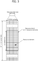
- FIG. 3 shows an example of a resource grid for one downlink slot.
- the downlink slot includes a plurality of Orthogonal Frequency Division Multiplexing (OFDM) symbol in the time domain and includes N RB Resource Blocks (RBs) in the frequency domain.
- the RBs includes one slot in the time domain and a plurality of consecutive subcarrier in the frequency domain in a resource allocation unit.
- the number of RBs N RB included in the downlink slot depends on a downlink transmission bandwidth N DL configured in a cell.
- the N RB can be any one of 6 to 110.
- An uplink slot can have the same structure as the downlink slot.
- Each element on the resource grid is called a Resource Element (RE).
- the RE on the resource grid can be identified by an index pair (k,l) within a slot.
- the number of OFDM symbols and the number of subcarriers within an RB are not limited thereto.
- the number of OFDM symbols and the number of subcarriers can be changed in various ways depending on the length of a CP, frequency spacing, etc.
- one OFDM symbol one of 128, 256, 512, 1024, 1536, and 2048 can be selected and used as the number of subcarriers.
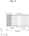
- FIG. 4 shows the structure of a DL subframe.
- a downlink (DL) subframe is divided into a control region and a data region in the time domain.
- the control region includes a maximum of former 3 (maximun 4 according to circumstances) OFDM symbols of a first slot within a subframe, but the number of OFDM symbols included in the control region can be changed.
- a control channel different from a physical downlink control channel (PDCCH) is allocated to the control region, and a physical downlink shared channel (PDSCH) is allocated to the data region.
- PDCCH physical downlink control channel
- PDSCH physical downlink shared channel
- physical channels can be divided into a physical downlink shared channel (PDSCH) and a physical uplink shared channel (PUSCH), that is, data channels, and a physical downlink control channel (PDCCH), a physical control format indicator channel (PCFICH), a physical hybrid-ARQ indicator channel (PHICH), and a physical uplink control channel (PUCCH), that is, control channels.
- PDSCH physical downlink shared channel
- PUSCH physical uplink shared channel
- PCFICH physical control format indicator channel
- PHICH physical hybrid-ARQ indicator channel
- PUCCH physical uplink control channel
- a PCFICH that is transmitted in the first OFDM symbol of a subframe carries a Control Format Indicator (CFI) regarding the number of OFDM symbols (i.e., the size of a control region) that are used to send control channels within the subframe.
- CFI Control Format Indicator
- UE first receives a CFI on a PCFICH and then monitors PDCCHs.
- a PCFICH is not subject to blind decoding, but is transmitted through the fixed PCFICH resources of a subframe.
- a PHICH carries a positive-acknowledgement (ACK)/negative-acknowledgement (NACK) signal for an uplink Hybrid Automatic Repeat reQuest (HARQ).
- ACK positive-acknowledgement
- NACK negative-acknowledgement
- HARQ Hybrid Automatic Repeat reQuest
- An ACK/NACK signal for uplink (UL) data on a PUSCH which is transmitted by UE is transmitted on a PHICH.
- a physical broadcast channel is transmitted in the former 4 OFDM symbols of a second slot within the first subframe of a radio frame.
- the PBCH carries system information that is essential for UE to communicate with a BS, and system information transmitted through a PBCH is called a Master Information Block (MIB).
- MIB Master Information Block
- SIB System Information Block
- SIB System Information Block
- DCI Downlink Control Information
- DCI can include the resource allocation of a PDSCH (this is also called a DL grant), the resource allocation of a PUSCH (this is also called an UL grant), a set of transmit power control commands for individual MSs within a specific UE group and/or the activation of a Voice over Internet Protocol (VoIP).
- VoIP Voice over Internet Protocol
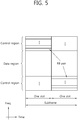
- FIG. 5 shows the structure of an UL subframe.
- the UL subframe can be divided into a control region to which a physical uplink control channel (PUSCH) for carrying uplink control information is allocated and a data region to which a physical uplink shared channel (PUSCH) for carrying user data is allocated in the frequency domain.
- PUSCH physical uplink control channel
- PUSCH physical uplink shared channel
- a PUCCH is allocated with an RB pair in a subframe. RBs that belong to an RB pair occupy different subcarriers in a fist slot and a second slot. An RB pair has the same RB index m.
- a PUCCH supports multiple formats.
- a PUCCH having a different number of bits in each subframe can be used according to a modulation scheme that is dependent on a PUCCH format.
- Table 2 shows an example of modulation schemes and the number of bits per subframe according to PUCCH formats.
- PUCCH format Modulation scheme Number of bits per subframe 1 N/A N/A 1a BPSK 1 1b QPSK 2 2 QPSK 20 2a QPSK+BPSK 21 2b QPSK+QPSK 22
- the PUCCH format 1 is used to send a Scheduling Request (SR), the PUCCH formats 1a/1b are used to send an ACK/NACK signal for an HARQ, the PUCCH format 2 is used to send a CQI, and the PUCCH formats 2a/2b are used to send a CQI and an ACK/NACK signal at the same time.
- SR Scheduling Request
- the PUCCH formats 1a/1b are used to send a CQI
- the PUCCH formats 2a/2b are used to send a CQI and an ACK/NACK signal at the same time.
- the PUCCH formats 1a/1b are used.
- the PUCCH format 1 is used.
- the PUCCH format 1 is used. In this case, the ACK/NACK signal is modulated into resources allocated to the SR and is then transmitted.
- All the PUCCH formats use the Cyclic Shift (CS) of a sequence in each OFDM symbol.
- a CS sequence is generated by cyclically shifting a base sequence by a specific CS amount.
- the specific CS amount is indicated by a CS index.
- u is a root index
- n is an element index wherein 0 ⁇ n ⁇ N-1
- N is the length of the base sequence.
- b(n) is defined in section 5.5 of 3GPP TS 36.211 V8.7.0.
- the length of a sequence is the same as the number of elements included in the sequence.
- U can be determined by a cell identifier (ID), a slot number within a radio frame, etc.
- the length N of the base sequence becomes 12 because one resource block includes 12 subcarriers.
- a different base sequence is defined depending on a different root index.
- a CS sequence r(n, I cs ) can be generated by cyclically shifting the base sequence r(n) as in Equation 2.
- r n I cs r n ⁇ exp j 2 ⁇ I cs n N , 0 ⁇ I cs ⁇ N ⁇ 1
- I cs is a CS index indicative of a CS amount (0 ⁇ I cs ⁇ N-1).
- An available CS index of a base sequence refers to a CS index that can be derived from the base sequence according to a CS interval.
- the length of a base sequence is 12 and a CS interval is 1, a total number of available CS indices of the base sequence becomes 12.
- a total number of available CS indices of the base sequence becomes 6.
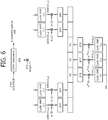
- FIG. 6 shows the channel structure of the PUCCH format 1b in a normal CP.
- One slot includes 7 OFDM symbols, the 3 OFDM symbols become Reference Signal (RS) OFDM symbols for a reference signal, and the 4 OFDM symbols become data OFDM symbols for an ACK/NACK signal.
- RS Reference Signal
- a modulation symbol d(0) is generated by performing Quadrature Phase Shift Keying (QPSK) modulation on an encoded 2-bit ACK/NACK signal.
- QPSK Quadrature Phase Shift Keying
- a CS index I cs can vary depending on a slot number 'ns' within a radio frame and/or a symbol index '1' within a slot.
- the modulation symbol d(0) is spread into a CS sequence r(n,Ics). Assuming that a 1-dimensional spread sequence corresponding to an (i+1) th OFDM symbol is m(i) in a slot,
- the 1-dimensional spread sequence can be spread using an orthogonal sequence.
- K a spreading factor
- a different spreading factor can be used in each slot.
- the 2-dimensional spread sequences ⁇ s(0), s(1), s(2), s(3) ⁇ are subject to IFFT and then transmitted in a corresponding OFDM symbol. Accordingly, an ACK/NACK signal is transmitted on a PUCCH.
- An orthogonal sequence index i, a CS index I cs , and an RB index m are parameters necessary to configure a PUCCH and are also resources used to classify PUCCHs (or MSs). If the number of available CSs is 12 and the number of available orthogonal sequence indices is 3, a PUCCH for a total of 36 MSs can be multiplexed with one RB.
- a resource index n (1) PUCCH is defined so that UE can obtain the three parameters for configuring a PUCCH.
- the resource index n (1) PUCCH n ccE + N (1) PUCCH , wherein n CCE is the number of the first CCE used to send a corresponding PDCCH (i.e., PDCCH including the allocation of DL resources used to received downlink data corresponding to an ACK/NACK signal), and N (1) PUCCH is a parameter that is informed of UE by a BS through a higher layer message.
- Time, frequency, and code resources used to send an ACK/NACK signal are called ACK/NACK resources or PUCCH resources.
- an index of ACK/NACK resources (called an ACK/NACK resource index or PUCCH index) used to send an ACK/NACK signal on a PUCCH can be represented as at least one of an orthogonal sequence index i, a CS index I cs , an RB index m, and an index for calculating the 3 indices.
- ACK/NACK resources can include at least one of an orthogonal sequence, a CS, a resource block, and a combination of them.
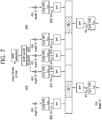
- FIG.7 shows the channel structure of the PUCCH formats 2/2a/2b in a normal CP.
- OFDM symbols 1 and 5 are used to send a demodulation reference signal (DM RS),t hat is, an uplink reference signal, and the remaining OFDM symbols are used to send a CQI.
- DM RS demodulation reference signal
- an OFDM symbol 3 fourth symbol is used for a DM RS.
- 10 CQI information bits can be subject to channel coding at a 1/2 code rate, for example, thus becoming 20 coded bits.
- Reed-Muller code can be used in the channel coding.
- the 20 coded bits are scramble and then subject to QPSK constellation mapping, thereby generating a QPSK modulation symbol (d(0) to d(4) in a slot 0).
- Each QPSK modulation symbol is modulated in a cyclic shift of a base RS sequence 'r(n)' having a length of 12, subject to IFFT, and then transmitted in each of 10 SC-FDMA symbols within a subframe.
- Uniformly spaced 12 CSs enable 12 different MSs to be orthogonally multiplexed in the same PUCCH RB.
- Abase RS sequence 'r(n)' having a length of 12 can be used as a DM RS sequence applied to OFDM symbols 1 and 5.
- FIG. 8 shows an example of a channel structure of a PUCCH format 3.
- the PUCCH format 3 is a PUCCH format which uses a block spreading scheme.
- the block spreading scheme means a method of spreading a symbol sequence, which is obtained by modulating a multi-bit ACK/NACK, in a time domain by using a block spreading code.
- a symbol sequence (e.g., ACK/NACK symbol sequence) is transmitted by being spread in the time domain by using the block spreading code.
- An orthogonal cover code (OCC) may be used as the block spreading code.
- Control signals of several UEs may be multiplexed by the block spreading code.
- a symbol e.g., d(0), d(1), d(2), d(3), d(4), etc., of FIG. 7
- UE multiplexing is performed using the cyclic shift of a constant amplitude zero auto-correlation (CAZAC) sequence.
- CAZAC constant amplitude zero auto-correlation
- a symbol sequence including one or more symbols is transmitted in a frequency domain of each data symbol, the symbol sequence is spread in a time domain by using the block spreading code, and UE multiplexing is performed.
- An example in which 2 RS symbols are used in one slot has been illustrated in FIG. 8 , but the present invention is not limited thereto. 3 RS symbols may be used, and an OCC having a spreading factor value of 4 may be used.
- An RS symbol may be generated from a CAZAC sequence having a specific cyclic shift and may be transmitted in such a manner that a plurality of RS symbols in the time domain has been multiplied by a specific OCC.
- the carrier aggregation system is also called a multiple carrier system.
- a 3GPP LTE system supports a case where a DL bandwidth and a UL bandwidth are differently configured, but one component carrier (CC) is a precondition in this case.
- a 3GPP LTE system supports a maximum of 20 MHz and may be different in a UL bandwidth and a DL bandwidth, but supports only one CC in each of UL and DL
- a carrier aggregation also called a bandwidth aggregation or a spectrum aggregation
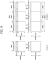
- FIG. 9 shows an example of a comparison between a single carrier system and a carrier aggregation system.
- a carrier aggregation system ( FIG. 9(b) ) has been illustrated as including three DL CCs and three UL CCs, but the number of DL CCs and UL CCs is not limited.
- a PDCCH and a PDSCH may be independently transmitted in each DL CC, and a PUCCH and a PUSCH may be independently transmitted in each UL CC. Or, a PUCCH may be transmitted only through a specific UL CC.
- a UE Since three pairs of DL CCs and UL CCs are defined, it can be said that a UE is served from three serving cells.
- a serving cell a cell which is configured to provide a service to a user equipment is referred to a serving cell.
- the UE may monitor PDCCHs in a plurality of DL CCs and receive DL transport blocks through the plurality of DL CCs at the same time.
- the UE may send a plurality of UL transport blocks through a plurality of UL CCs at the same time.
- a pair of a DL CC #A and a UL CC #A may become a first serving cell
- a pair of a DL CC #B and a UL CC #B may become a second serving cell
- a DL CC #C and a UL CC#C may become a third serving cell.
- Each serving cell may be identified by a cell index (CI).
- the CI may be unique within a cell or may be UE-specific.
- the serving cell may be divided into a primary cell and a secondary cell.
- the primary cell is a cell on which the UE performs an initial connection establishment procedure or initiates a connection re-establishment procedure, or a cell designated as a primary cell in a handover process.
- the primary cell is also called a reference cell.
- the secondary cell may be configured after an RRC connection has been established and may be used to provide additional radio resources. At least one primary cell is always configured, and a secondary cell may be added/modified/released in response to higher layer signaling (e.g., an RRC message).
- the CI of the primary cell may be fixed. For example, the lowest CI may be designated as the CI of the primary cell.
- the primary cell includes a downlink primary component carrier (DL PCC) and an uplink PCC (UL PCC) in view of a CC.
- the secondary cell includes only a downlink secondary component carrier (DL SCC) or a pair of a DL SCC and a UL SCC in view of a CC.
- DL SCC downlink secondary component carrier
- 'cell' may be mixed with the term 'component carrier (CC)'.
- the carrier aggregation system may support a plurality of CCs, that is, a plurality of serving cells unlike the single carrier system.
- Such a carrier aggregation system may support cross-carrier scheduling.
- the cross-carrier scheduling is a scheduling method capable of performing resource allocation of a PDSCH transmitted through a different component carrier through a PDCCH transmitted through a specific component carrier and/or resource allocation of a PUSCH transmitted through other component carriers except for a component carrier fundamentally linked with the specific component carrier. That is, the PDCCH and the PDSCH may be transmitted through different DL CCs, and a PUSCH may be transmitted through a UL CC different from a UL CC linked with a DL CC to which a PDCCH including a UL is transmitted.
- the PDCCH needs a carrier indicator indicating that PDSCH/PUSCH are transmitted through a certain DL CC/UL CC.
- a field including the carrier indicator refers to a carrier indication field (CIF).
- the carrier aggregation system that supports the cross-carrier scheduling may include a carrier indication field (CIF) to the conventional downlink control information (DCI).
- CIF carrier indication field
- DCI downlink control information
- 3 bits may be extended since the CIF is added to the conventional DCI format (i.e., the DCI format used in LTE), and the PDCCH structure may reuse the conventional coding method, resource allocation method (i.e., resource mapping based on the CCE), and the like.
- a BS may set a PDCCH monitoring DL CC (monitoring CC) group.
- the PDCCH monitoring DL CC group is configured by a part of all aggregated DL CCs. If the cross-carrier scheduling is configured, the UE performs PDCCH monitoring/decoding for only a DL CC included in the PDCCH monitoring DL CC group. That is, the BS transmits a PDCCH with respect to a PDSCH/PUSCH to be scheduled through only the DL CCs included in the PDCCH monitoring DL CC group.
- the PDCCH monitoring DL CC group may be configured in a UE-specific, UE group-specific, or cell-specific manner.
- Non-cross carrier scheduling is a scheduling method capable of performing resource allocation of a PDSCH transmitted through a specific component carrier through a PDCCH transmitted through the specific component carrier and/or resource allocation of a PDSCH transmitted through a component carrier fundamentally linked with the specific component carrier.
- a DL subframe and an UL subframe coexist in one radio frame.
- the number of UL subframes is smaller than that of DL subframes. Accordingly, in preparation for a case where UL subframes for sending an ACK/NACK signal are not sufficient, a plurality of ACK/NACK signals for DL transport blocks received in a plurality of DL subframes is transmitted in one UL subframe.
- UE In ACK/NACK bundling, UE sends ACK if it has successfully decoded all received PDSCHs (i.e., DL transport blocks) and sends NACK in other cases. To this end, ACK or NACKs for each PDSCH are compressed through logical AND operations.
- ACK/NACK multiplexing is also called ACK/NACK channel selection (or simply channel selection).
- UE selects one of a plurality of PUCCH resources and sends ACK/NACK.
- Table below shows DL subframes n-k associated with an UL subframe n according to an UL-DL configuration in 3GPP LTE, wherein k ⁇ K and M is the number of elements of a set K.
- UL-DL Configuration Subframe n 0 1 2 3 4 5 6 7 8 9 0 - - 6 - 4 - - 6 - 4 1 - - 7, 6 4 - - - 7, 6 4 - 2 - - 8, 7, 4, 6 - - - - 8, 7, 4, 6 - - 3 - - 7, 6, 11 6, 5 5, 4 - - - - - 4 - 12, 8, 7, 11 6, 5, 4, 7 - - - - - - - 5 - - 13, 12, 9, 8, 7, 5, 4, 11, 6 - - - - - - - 6 - - 7 7 5 - - 7 7 - - 7 - - 7 - - 7 - - 7 - - 7
- UE can obtain 3 PUCCH resources n (1) PUCCH,0 , n (1) PUCCH,1 , and n (1) PUCCH,2 because it can receive 3 PDCCHs from 3 DL subframes.
- an example of ACK/NACK channel selection is the same as the following table.
- HARQ-ACK(0),HARQ-ACK(1),HARQ-ACK(2) n PUCCH b(0),b(1) ACK, ACK, ACK n (1) PUCCH,2 1,1 ACK, ACK, NACK/DTX n (1) PUCCH,1 1,1 ACK, NACK/DTX, ACK n (1) PUCCH,0 1,1 ACK, NACK/DTX, NACK/DTX n (1) PUCCH,0 0,1 NACK/DTX, ACK, ACK n (1) PUCCH,2 1,0 NACK/DTX, ACK, NACK/DTX n (1) PUCCH,1 0,0 NACK/DTX, NACK/DTX, ACK n (1) PUCCH,2 0,0 DTX, DTX, NACK n (1) PUCCH,2 0,1 DTX, NACK, NACK/DTX n (1) PUCCH,2 0,1 DTX, NACK, NACK/DTX n (1) PUCCH,1 1,0 NACK, NACK/DTX
- HARQ-ACK(i) indicates ACK/NACK for an i th DL subframe of M DL subframes.
- Discontinuous transmission means that a DL transport block has not been received on a PDSCH in a corresponding DL subframe or that a corresponding PDCCH has not been detected.
- 3 PUCCH resources n (1) PUCCH,0 , n (1) PUCCH,1 , and n (1) PUCCH,2 are present, and b(0), b(1) are two bits transmitted using a selected PUCCH.
- ACK/NACK channel selection if at least one ACK is present, NACK and DTX are coupled. This is because all ACK/NACK states cannot be represented by a combination of reserved PUCCH resources and a QPSK symbol. If ACK is not present, however, DTX is decoupled from NACK.
- the above-described ACK/NACK bundling and ACK/NACK multiplexing can be applied in the case where one serving cell has been configured in UE in TDD.
- UE sends ACK/NACK in a subframe n if the UE detects a PDSCH indicated by a corresponding PDCCH in a subframe n-k of a primary cell or detects a Semi-Persistent Scheduling (SPS) release PDCCH.
- SPS Semi-Persistent Scheduling
- a BS can inform UE that semi-persistent transmission and reception are performed in what subframes through a higher layer signal, such as Radio Resource Control (RRC). Parameters given by the higher layer signal can be, for example, the periodicity of a subframe and an offset value.
- RRC Radio Resource Control
- the UE When the UE receives the activation or release signal of SPS transmission through a PDCCH after recognizing semi-persistent transmission through the RRC signaling, the UE performs or releases SPS PDSCH reception or SPS PUSCH transmission. That is, the UE does not immediately perform SPS transmission/reception although SPS scheduling is allocated thereto through the RRC signaling, but when an activation or release signal is received through a PDCCH, performs SPS transmission/reception in a subframe that corresponds to frequency resources (resource block) according to the allocation of the resource block designated by the PDCCH, modulation according to MCS information, a subframe periodicity allocated through the RRC signaling according to a code rate, and an offset value.
- a PDCCH that releases SPS is called an SPS release PDCCH
- a DL SPS release PDCCH that releases DL SPS transmission requires the transmission of an ACK/NACK signal.
- UE sends ACK/NACK using the PUCCH formats 1a/1b according to a PUCCH resource n (1,p) PUCCH .
- n (1,p) PUCCH indicates an antenna port p.
- the k is determined by Table 5.
- n (1,p) PUCCH can be allocated as in the following equation.
- P can be p0 or p1.
- Equation 3 c is selected in such a way as to satisfy N c ⁇ n ccE ⁇ N c+1 (antenna port p0), N c ⁇ (n CCE + 1) ⁇ N c+1 (antenna port p1) from among ⁇ 0,1,2,3 ⁇ .
- N (1) PUCCH is a value set by a higher layer signal.
- N c max ⁇ 0, floor [N DL RB ⁇ (N RB sc ⁇ c - 4)/36] ⁇ .
- the N DL RB is a DL bandwidth
- N RB sc is the size of an RB indicated by the number of subcarriers in the frequency domain.
- n CCE is a first CCE number used to send a corresponding PDCCH in a subframe n-km.
- m is a value that makes km the smallest value in the set K of Table 5.
- the UE can send ACK/NACK in the subframe n using the PUCCH resource n (1,p) PUCCH as follows.
- an SPS PDSCH does not include a scheduling PDCCH
- UE sends ACK/NACK through the PUCCH formats 1a/1b according to n (1,p) PUCCH that is configured by a higher layer signal.
- 4 resources a first PUCCH resource, a second PUCCH resource, a third PUCCH resource, and a fourth PUCCH resource
- one resource can be indicated through the Transmission Power Control (TPC) field of a PDCCH that activates SPS scheduling.
- TPC Transmission Power Control
- TPC field value Resource for channel selection '00' First PUCCH resource '01' Second PUCCH resource '10' Third PUCCH resource '11' Fourth PUCCH resource
- one serving cell is configured (i.e., only a primary cell is configured) in UE, ACK/NACK multiplexing is used, and M>1. That is, it is assumed that a plurality of DL subframes is associated with one UL subframe.
- N C max ⁇ 0, floor [N DL RB ⁇ (N RB sc ⁇ c - 4)/36] ⁇ .
- the N DL RB is a DL bandwidth
- N RB sc is the size of an RB indicated by the number of subcarriers in the frequency domain.
- n CCE,i is a first CCE number used to send a corresponding PDCCH in the subframe n - k i .
- the UE sends ACK/NACK using channel selection that uses the PUCCH format 1b or the PUCCH format 3.
- Channel selection that uses the PUCCH format 1b used in TDD can be performed as follows.
- UE performs spatial ACK/NACK bundling on a plurality of codewords within one DL subframe and sends spatially bundled ACK/NACK bits for each serving cell through channel selection that uses the PUCCH format 1b.
- Spatial ACK/NACK bundling means the compression of ACK/NACK for each codeword through logical AND operations within the same DL subframe.
- ACK/NACK bits are 4 bits or lower, spatial ACK/NACK bundling is not used and the ACK/NACK bits are transmitted through channel selection that uses the PUCCH format 1b.
- ACK/NACK bits are greater than 20 bits
- spatial ACK/NACK bundling can be performed in each serving cell and ACK/NACK bits subjected to spatial ACK/NACK bundling can be transmitted through the PUCCH format 3. If ACK/NACK bits are 20 bits or lower, spatial ACK/NACK bundling is not used and the ACK/NACK bits are transmitted through the PUCCH format 3.
- ACK/NACK can be transmitted through channel selection that uses the PUCCH format 1b.
- the UE can feed ACK/NACK for a maximum of 2 transport blocks, received in one serving cell, back to a BS by sending 2-bit (b(0)b(1)) information in one PUCCH resource selected from a plurality of PUCCH resources.
- One codeword can be transmitted in one transport block.
- a PUCCH resource can be indicated by a resource index n (1) PUCCH,i .
- A is any one of ⁇ 2, 3, 4 ⁇ , and i is 0 ⁇ i ⁇ (A-1).
- the 2-bit information is indicated as b(0)b(1).
- HARQ-ACK(j) indicates an HARQ ACK/NACK response that is related to a transport block or DL SPS release PDCCH transmitted by a serving cell.
- the HARQ-ACK(j), the serving cell, and the transport block can have the following mapping relationship.
- [Table 8] A HARQ-ACK(j) HARQ-ACK(0) HARQ-ACK(1) HARQ-ACK(2) HARQ-ACK(3) 2 Transport block 1 of primary cell Transport block 2 of secondary cell NA NA 3 Transport block 1 of serving cell 1 Transport block 2 of serving cell 1 Transport block 3 of serving cell 2 NA 4 Transport block 1 of primary cell Transport block 2 of primary cell Transport block 3 of secondary cell Transport block 4 of secondary cell
- HARQ-ACK(0) and HARQ-ACK(1) indicate ACK/NACKs for 2 transport blocks transmitted in a primary cell
- HARQ-ACK(2) and HARQ-ACK(3) indicate ACK/NACKs for 2 transport blocks transmitted in a secondary cell.
- n (1) PUCCH,i is determined to be n CCE,i +N (1) PUCCH .
- n CCE,i means an index of the first CCE that is used to send a PDCCH by a BS, and N (1) PUCCH is a value set through a higher layer signal. If a transmission mode of a primary cell supports up to two transport blocks, a PUCCH resource n (1) PUCCH,i+1 is given.
- n (1) PUCCH,i+1 can be determined to be n CCE,i + 1 + N (1) PUCCH . That is, if a primary cell is set in a transmission mode in which a maximum of up to 2 transport blocks can be transmitted, 2 PUCCH resources can be determined.
- PUCCH resources n (1) PUCCH,i and n (1) PUCCH,i+1 for a transmission mode in which up to 2 transport blocks are supported can be determined by a higher layer configuration.
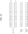
- FIG. 10 shows one example in which a plurality of serving cells use different types of radio frames in a wireless communication system.
- a primary cell PCell and a plurality of secondary cells SCell #1, ... , SCell #N may be configured in a UE.
- the primary cell may operate in FDD and use an FDD frame
- the secondary cells may operate in TDD and use TDD frames.
- the same UL-DL configuration may be used in the plurality of secondary cells.
- a DL subframe (indicated by D) and a UL subframe (indicated by U) are present in a 1:1 manner in the primary cell, but a DL subframe and a UL subframe may be present in a different ratio other than 1:1 in the secondary cells.
- Table 9 shows that ACK/NACK is transmitted in what a subframe according to a UL-DL configuration when one serving cell operates in TDD.
- Table 9 is equivalent to Table 5.
- UL-DL Configuration Subframe n 0 1 2 3 4 5 6 7 8 9 0 4 6 - 4 6 - 1 7 6 4 7 6 4 2 7 6 4 8 7 6 4 8 3 4 11 7 6 6 5 5 4 12 11 8 7 7 6 5 4 5 12 11 9 8 7 6 5 4 13 6 7 7 7 7 5
- Table 9 when a UE receives a PDSCH or a PDCCH (e.g., DL SPS release PDCCH) necessary for an ACK/NACK response in a subframe n, the UE sends ACK/NACK in a subframe n + k(n).
- Each of the values of Table 9 indicates the k(n) value.
- Table 9 indicates that if a UL-DL configuration is 0 and a PDSCH is received in a subframe 0, ACK/NACK is transmitted after four subframes elapse, i.e., in a subframe 4. A specific time is necessary in order for the UE to send ACK/NACK after receiving a PDSCH or a DL SPS release PDCCH.
- a minimum value of this specific time is hereinafter indicated as k min , and a value of k min may be four subframes.
- Four subframes, which is the minimum value of the specific time, are determined by considering a propagation delay between the transmission terminal and the reception terminal, a processing time which is required for decoding at the reception terminal.
- the ACK/NACK is mainly transmitted in the first uplink subframe after a lapse of k min .
- the underlined figures do not indicate the first uplink subframe after a lapse of k min , but indicate the uplink subframe which is located at the next position. The reason for this is to prevent from transmitting the ACK/NACK for too many downlink subframes in one uplink subframe.
- a primary cell and at least one secondary cell are configured in a UE in a wireless communication system. It is also assumed that the primary cell uses an FDD frame and the secondary cell uses a TDD frame. Any one of the UL-DL configurations of Table 1 may be used in the TDD frame.
- a relationship between a primary cell and one secondary cell is illustrated, for convenience of description, but this relationship may be applied to a relationship between a primary cell and each of a plurality of secondary cells when the plurality of secondary cells are configured in the UE.
- the downlink data generally indicates a PDSCH that requests an ACK/NACK response, a codeword included in a PDSCH, a DL SPS release PDCCH indicating a DL SPS release and the like.
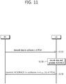
- FIG. 11 shows a method of transmitting ACK/NACK for downlink data received through a primary cell.
- a BS sends downlink data in a subframe n of a primary cell (S110). From a view of a UE, the downlink data is received in a subframe n of a DL PCC of the primary cell.
- the UE decodes the downlink data and generates ACK/NACK for the downlink data (S120).
- the UE sends the ACK/NACK in a subframe n + k PCC (n) of the primary cell (S130).
- the subframe n + k PCC (n) of the primary cell is a subframe after a minimum delay time (this is called k min ) necessary for an ACK/NACK response has elapsed from a point of time at which the downlink data was received.
- the minimum delay time k min may be four subframes. Accordingly, the UE may send the ACK/NACK in a subframe n + 4 of a UL PCC of the primary cell.
- the ACK/NACK is transmitted in a subframe after four subframes elapse from a subframe in which data was received.
- FIG. 12 shows a method of transmitting ACK/NACK for downlink data received through a secondary cell.
- a BS sends information about a UL-DL configuration of the secondary cell (S210).
- the secondary cell may need the UL-DL configuration information because it operates in TDD.
- the UL-DL configuration information may be transmitted through a higher layer signal, such as an RRC message.
- a BS sends downlink data in a subframe n of the secondary cell (S220).
- the UE decodes the downlink data and generates ACK/NACK for the downlink data (S230).
- the UE may send the ACK/NACK to the BS through a subframe n + kscc(n) of a primary cell (S240).
- the subframe n + k SCC (n) may be determined by the following method.
- Method 1 is a method in which a subframe n + k SCC (n) complies with ACK/NACK transmission timing in a primary cell. That is, Method 1 is a method of configuring a UL subframe of the primary cell equal to n+k min as the subframe n + k SCC (n). In other words, if data is received in a subframe n of a secondary cell, ACK/NACK for the data is transmitted in the subframe n + k min of the primary cell.
- k min may be, for example, four subframes.
- FIG. 13 shows an example of ACK/NACK transmission timing when a primary cell is an FDD cell and a secondary cell is a TDD cell.
- a UL subframe of PCC in which ACK/NACK is transmitted for a DL data channel or DL control channel received in a DL subframe n of PCC is a subframe n + k PCC (n).
- a UL subframe of PCC in which ACK/NACK is transmitted for a DL data channel or DL control channel received in a DL subframe n of SCC is a subframe n + kscc(n).
- ACK/NACK for a DL data channel or DL control channel received in a subframe n 131 of SCC is transmitted in a subframe n+4 132 of PCC.
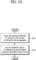
- FIG. 14 shows an ACK/NACK transmission method based on Method 1.
- the data requiring ACK/NACK collectively refers to data requiring an ACK/NACK response such as a PDSCH, a transport block, and a DL SPS release PDCCH.
- the 1 st cell is an FDD cell using an FDD frame, and may be a primary cell.
- the 2 nd cell is a TDD cell using a TDD frame, and may be a secondary cell.
- a UE transmits ACK/NACK for the data in a UL subframe of the 1 st cell determined according to ACK/NACK timing of the 1 st cell (S162).
- Method 1 is advantageous in that ACK/NACK transmission is distributed.
- the number of ACK/NACK resources that need to be secured in the subframe n may be determined by a transmission mode of the primary cell for a subframe n - k min and a transmission mode in a DL subframe of the secondary cell.
- ACK/NACK timing applied to the UE may be represented by changing Table 5 into Table 10 below.
- Table 10 UL-DL Configuration Subframe n 0 1 2 3 4 5 6 7 8 9 0 4 - - 4 4 - - 4 1 4 - - 4 4 4 - - 4 4 2 4 - 4 4 4 4 - 4 4 4 3 4 4 4 4 4 4 4 - - - 4 4 4 4 4 4 4 - - 4 4 5 4 4 4 4 4 4 - 4 4 4 6 4 - 4 4 4 - 4
- a subframe n is a subframe in which ACK/NACK is transmitted and a number indicated in the subframe n indicates k min .
- the subframe n - k min indicates a subframe in which downlink data, that is, the subject of ACK/NACK, is received.
- ACK/NACK timing applied to the UE may be represented by changing Table 9 into Table 11 below.
- Table 11 UL-DL Configuration Subframe n 0 1 2 3 4 5 6 7 8 9 0 4 4 - 4 4 - 1 4 4 4 4 4 4 2 4 4 4 4 4 4 4 4 4 4 3 4 4 4 4 4 4 4 4 4 4 4 4 4 4 4 5 4 4 4 4 4 4 4 4 4 4 4 4 4 4 4 4 4 4 4 4 4 4 4 4 4 4 4 5 4 4 4 4 4 4 4 4 4 4 4 4 4 4 4 4 4 4 4 4 4 4 4 4 4 4 4 4 4 4 4 4 4 4 4 4 4 4 4 4 4 4 4 4 4 4 4 5 4 4 4 4 4 4 4 4 4 4 4 4 4 4 4 4 4 4 4 4 4 4 4 4 4 4 4 4 4 4 4 4 4 4 4 4 4 4 4 4
- a subframe n indicates a subframe in which downlink data is received.
- a subframe n + k SCC (n) is a subframe in which ACK/NACK for the downlink data is transmitted.
- Each of values in Table 11 indicates a k SCC (n) value for the subframe n. For example, it indicates that, if a UL-DL configuration is 0 and downlink data is received in the subframe 1 of a secondary cell, ACK/NACK is transmitted in a subframe 5 (of a primary cell) after four subframes elapse.
- Tables 10 and 11 and FIG. 13 have a precondition that the radio frame boundaries of a secondary cell and a primary cell are the same. That is, it is a precondition that the radio frame of the primary cell is synchronized with the radio frame of the secondary cell. If the radio frame of the primary cell is not synchronized with the radio frame of the secondary cell, additional subframe delay (indicated by k add ) for compensating for this asynchronization may be taken into consideration. That is, in Method 1, k SCC (n) may be changed into k min + k add .
- scheduling may be limited so that the downlink data is not transmitted in the subframe n of the secondary cell.
- Method 2 is a method of determining a subframe n + k SCC (n) in which ACK/NACK is transmitted based on TDD ACK/NACK transmission timing in a secondary cell. That is, kscc(n) is determined as in Table 9, but actual ACK/NACK is transmitted through the UL PCC of a primary cell. In other words, ACK/NACK for a DL data channel or DL control channel received in SCC may be transmitted in a UL subframe of PCC according to ACK/NACK timing configured in SCC.
- FIG. 15 shows another example of ACK/NACK transmission timing when a primary cell is an FDD cell and a secondary cell is a TDD cell.
- a UL subframe of PCC in which ACK/NACK is transmitted for a DL data channel or DL control channel received in a DL subframe n of PCC is a subframe n + k PCC (n).
- ACK/NACK for a DL data channel or DL control channel received in a DL sub frame n 141 of SCC may be transmitted in a UL sub frame n+k(n) 142 of SCC when ACK/NACK timing configured in SCC is applied.
- the ACK/NACK is transmitted in a UL subframe 143 of PCC at a time equal to that of the UL subframe n+k(n) 142.
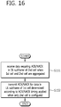
- FIG. 16 shows an ACK/NACK transmission method based on Method 2.
- the data requiring ACK/NACK refers to data requiring an ACK/NACK response such as a PDSCH, a transport block, and a DL SPS release PDCCH.
- the 1 st cell is an FDD cell using an FDD frame, and may be a primary cell.
- the 2 nd cell is a TDD cell using a TDD frame, and may be a secondary cell.
- AUE transmits ACK/NACK for the data in a UL subframe of the 1 st cell determined according to ACK/NACK timing applied when only the 2 nd cell is configured (S152).
- Such a method has an advantage in that ACK/NACK timing for TDD CC may be equally applied irrespective of whether the TDD CC is used as a primary cell or secondary cell.
- the number of resources for ACK/NACK transmission, which must be ensured in a UL subframe of PCC, is determined according to whether a DL subframe is present in a PCC/SCC at a subframe n and according to a transmission mode at the present DL subframe.
- k add additional subframe delay (indicated by k add ) for compensating for this asynchronization may be taken into consideration.
- the k add may be a fixed value or may be a value set through an RRC message.
- ACK/NACK for downlink data received in the subframe n of the secondary cell may be represented as being transmitting in the UL subframe n + k' SCC (n) of the primary cell.
- scheduling may be limited so that the downlink data is not transmitted in the subframe n of the secondary cell.
- Method 1 is used as the method of transmitting ACK/NACK in a primary cell and the method of transmitting ACK/NACK for a secondary cell
- the ACK/NACK for the primary cell and the secondary cell may comply with an ACK/NACK transmission scheme used in FDD.
- channel selection may be used in which the PUCCH format 1b used in FDD is used when a plurality of serving cells are configured in a UE. That is, ACK/NACK for the secondary cell is transmitted using channel selection that uses the PUCCH format 1b through the primary cell without using a compression scheme, such as ACK/NACK bundling.
- a compression scheme, such as ACK/NACK bundling may not be used because only one DL subframe is associated with one UL subframe of the primary cell.
- Method 2 is used as the method of transmitting ACK/NACK in a primary cell and the method of transmitting ACK/NACK for a secondary cell
- the ACK/NACK for the primary cell and the secondary cell may comply with an ACK/NACK transmission scheme used in TDD.
- ACK/NACK may be transmitted through channel selection that uses the PUCCH format 1b used when a plurality of serving cells are configured in TDD.
- Method 1 and 2 may be determined according to whether to use cross carrier scheduling or non-cross carrier scheduling. For example, Method 1 may be used in the cross carrier scheduling and Method 2 may be used in the non-cross carrier scheduling.
- CCs to be aggregated use different frame structures (an aggregation of an FDD CC and a TDD CC), one CC may perform UL transmission and another CC may perform DL reception in the same time duration (or subframe). In this case, the UL transmission may have an effect on the DL reception. Therefore, it is not desirable to perform the UL transmission and the DL reception simultaneously in contiguous frequency bands.
- frequency bands separated enough not to be interfered from each other are grouped, so that the same UL-DL configuration is used in one group and different UL-DL configurations are used in different groups.
- CCs #1 to #5 are aggregated in an ascending order of an allocated frequency band
- the CCs #1 and #2 are grouped as a first group and the CCs #3 to #5 are grouped as a second group, and all CCs in the first group use a UL-DL configuration 0, and all CCs in the second group use a UL-DL configuration 3.
- the CC #2 and the CC #3 may be CCs separated enough not to be interfered from each other.
- a UE may have an independent RF module for each group, and may use a separate power amplifier. The UE may transmit one PUCCH for each group, and in this case, a problem of a peak to average ratio (PAPR) increase does not occur even if a plurality of PUCCHs are transmitted in uplink.
- PAPR peak to average ratio
- Method 1 may be applied, and if the PUCCH is transmitted in a specific UL CC of a group (of a non-contiguous frequency band) to which the PCC does not belong, ACK/NACK timing transmitted through the PUCCH may comply with ACK/NACK timing corresponding to a DL subframe of the specific UL CC in which the PUCCH is transmitted.
- a HARQ ACK/NACK transmission timing is described in a system in which CCs using different frame structures each other, and hereinafter, a HARQ ACK/NACK transmission technique will be described in which CCs using different frame structures with each other.
- the DL data channel received in the PCC/SCC and the ACK/NACK for the DL control channel may be transmitted using PUCCH format 1b that uses a channel selection used for aggregating among FDD cells.
- the multiplexing method used in case that UCIs different from the ACK/NACK are simultaneously generated and the rule of dropping a specific UCI are also applied to the multiplexing method and the dropping rule which are used in the FDD in the same manner. That is, the multiplexing method/the UCI dropping rule in the FDD which are optimized in case of connecting one UL subframe to one DL subframe is used.
- PUCCH format 1b that uses the channel selection for the ACK/NACK transmission is used, and the PUCCH resource and the constellation at the moment are the same as those of PUCCH format 1b. Accordingly, even in the section in which it is obscure whether a secondary cell is configured or in the situation that the configuration of a secondary cell is error, the ACK/NACK for the two codewords transmission in a primary cell may be transmitted without error.
- the ACK/NACK transmission for the UL PCC of the primary cell and the SCC for the secondary cell may follow the ACK/NACK transmission technique which is defined in the TDD cell (secondary cell).
- 'PUCCH format 1b that uses channel selection' which is defined in aggregating among TDD cells may be used. This is because one PCC UL subframe corresponds to a plurality of DL subframes of PCC and SCC, similar to the aggregation among the TDD cells.
- the multiplexing method used in case that UCIs different from the ACK/NACK are simultaneously generated and the dropping rule of a specific UCI, and so on are also applied to the multiplexing method and the dropping rule which are regulated in the TDD in the same manner.
- the ACK/NACK transmission method is used, which is used for aggregating among the TDD cells that use UL-DL configurations different from each other for M TDDcell combination.
- M cell indicates the number of DL subframes that correspond to one UL subframe, and the corresponding DL subframe may include only the DL data channel (PDSCH or DL HARQ) that requires the ACK/NACK response or the effective DL subframes that are available to receive the DL control channel (DL SPS release PDCCH).
- PDSCH DL data channel
- DL HARQ DL HARQ
- DL SPS release PDCCH the effective DL subframes that are available to receive the DL control channel
- any one of DL ACK/NACK timing of the DL cell corresponding to the PUCCH transmission cell or DL subframe follows the ACK/NACK timing defined for the TDD cell (or in case of M>1)
- the aggregation among cells using frame structures different from each other follows the DL ACK/NACK transmission technique defined in aggregating among the TDD cells.
- the ACK/NACK timing of the secondary cell may follow the ACK/NACK timing of the primary cell.
- the DL ACK/NACK transmission technique defined in aggregating among the TDD cells is used.
- a transmission technique for additional ACK/NACK timing may be introduced based on the DL ACK/NACK transmission technique defined in aggregating among the TDD cells.
- a channel selection technique is defined only for M ⁇ 4 conventionally, a channel selection technique for M>4 may be introduced.
- the selection of ACK/NACK transmission techniques may also be determined for each UL subframe.
- FDD method may be selected, and if the case of M:1 (M>1, i.e., if a plurality of DL subframes are connected to other UL subframes) is included, the TDD method may be applied to the other UL subframes.
- the ACK/NACK transmission technique may also be determined for each cell.
- a primary cell may be the FDD cell
- first and second secondary cells may be the TDD cell.
- the ACK/NACK for the data received in the first and second secondary cells may be transmitted.
- the ACK/NACK for the data received in the first secondary cell may follow the ACK/NACK transmission technique of the FDD method
- the ACK/NACK for the data received in the second secondary cell may follow the ACK/NACK transmission technique of the TDD method.
- the channel selection technique used in the aggregation among the TDD cells is used for the TDD ACK/NACK transmission method, when two codewords are transmitted in the primary cell, there is a disadvantage that the PUCCH resource and the in PUCCH format 1b that uses the channel selection becomes different from those of PUCCH format 1b.
- PUCCH format 1b that uses the channel selection as the PUCCH resource for [ACK, ACK, NACK/DTX, NACK/DTX] and [NACK/DTX, ACK, NACK/DTX, NACK/DTX], n (1) PUCCH,1 is selected.
- PUCCH format 1b as the PUCCH resource for [ACK, ACK] and [NACK/DTX, ACK], n (1) PUCCH,0 is selected.
- the HARQ ACK/NACK transmission technique may be changed for each subframe. That is, the ACK/NACK transmission technique may be changed depending on whether only the ACK/NACK for the data received in a first cell is transmitted in the UL subframe in which the ACK/NACK is transmitted or whether the ACK/NACK for the data received in both a first cell and a second cell is transmitted.
- the ACK/NACK of the FDD cell is transmitted together with the ACK/NACK of the TDD cell.
- the channel selection is not applied to all UL subframes in the FDD cell, but the channel selection may be applied to only the subframes in which the ACK/NACK of the FDD cell and the ACK/NACK of the TDD cell are transmitted together.
- PUCCH format 1a/1b is used.
- 'PUCCH format 1a/1b is used' means the ACK/NACK transmission technique in case that the FDD cell is unilaterally configured/used.
- the multiplexing method used in case that UCIs different from the ACK/NACK are simultaneously generated and the dropping rule of a specific UCI, and so on are also applied to the multiplexing method and the dropping rule in case that the FDD cell is unilaterally configured/used.
- PUCCH format 1a/1b may also be applied only to the case that transmission diversity is setup in the PUCCH transmission.
- the explicit resource which is explicitly designated should be used as a second PUCCH resource.
- method 2 is used in a situation that two cells are aggregated as shown in FIG. 15 , onto subframes 2 and 7 in the FDD cell, the ACK/NACK for the FDD cell and the ACK/NACK for the TDD cell are transmitted together, and onto the remaining subframes 0, 1, 3, 4, 5, 6, 8 and 9 of the FDD cell, only the ACK/NACK for the FDD cell is transmitted. Accordingly, a use of the channel selection method which is used in aggregating the TDD cells in all UL subframes of the FDD cells has a disadvantage that the ACK/NACK of a primary cell is also bundled (particularly, in case of M>1 in the TDD cell).
- PUCCH format 1a/1b may be used in the UL subframe in which the ACK/NACK of the TDD cell is not transmitted, and PUCCH format 1b that uses the channel selection defined in the aggregation among the TDD cells only in the UL subframe in which the ACK/NACK of the TDD cell is transmitted may be used.
- the ACK/NACK of a primary cell is unnecessarily space bundled and transmitted.
- the ACK/NACK of a primary cell is transmitted through the resource for SR use without the space bundling.
- PUCCH format 1b may also be used.
- the number of total UL subframes which are connected to the UL subframe in which the ACK/NACK is transmitted may be M. That is, total number of the DL subframe of a primary cell connected to the UL subframe of the primary cell and the DL subframe of a secondary cell may be M.
- M>4 may be occurred.
- a primary cell is the FDD cell and a secondary cell is the TDD cell
- more than four DL subframes may be connected to the UL subframe of the primary cell.
- the channel selection is not used for total UL subframes in the primary cell, and only PUCCH format 3 is used. That is, configuration of channel selection may be limited.
- total number of DL subframes which are connected to the UL subframe in which the ACK/NACK is transmitted may be M.
- the case of M>4 may be occurred. Since the channel selection is defined only for the case that M is 4 as the maximum, when the case of M>4 occurs, the case cannot be processed by the conventional technique. Accordingly, it is required to solve the case.
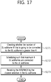
- FIG. 17 illustrates an ACK/NACK transmission method according to an embodiment of the present invention.
- a base station checks whether the number of DL subframe M that is going to be connected to the DL subframe is greater than 4 (step, S171).
- the base station performs scheduling such that maximum four DL subframes are connected to the UL subframe (step, S172). For example, in case that a primary cell is the TDD call and a secondary cell is the FDD cell, and in case of UL-DL configuration 2, 4 or 5, more than four DL subframes may be connected to the UL subframe of the primary cell. In this case, the base station performs scheduling the channel that requires the ACK/NACK only for four or less subframes among the M subframes.
- the base station receives the ACK/NACK by the channel selection in the UL subframe (step, S173).
- the ACK/NACK is transmitted by the channel selection in the UL subframe.
- a primary cell may be the TDD cell and a secondary cell may be the FDD cell.
- M P the number of DL subframes of the primary cell which is connected to the UL subframe of the primary cell
- M S the number of DL subframes of the secondary cell which is connected to the UL subframe of the primary cell.
- the base station may restrict the number of total DL subframes which is connected to one UL subframe by scheduling only M P DL subframes, not by scheduling all M S DL subframes. Based on this, a channel selection technique that the number of selected channel is M P may be selected. This is because the NACK transmission probability increases by the spatial bundling, the time domain bundling, etc. being applied, if the number of total DL subframes which is connected to one UL subframe increases.
- the spatial bundling is a technique that compresses the ACK/NACK for a plurality of codewords (transmission blocks) received in one subframe into one ACK/NACK by AND operation.
- the time bundling is a technique that the ACK/NACK determined in each of a plurality of subframes into one ACK/NACK by AND operation.
- a UE determines the situation in which more than four subframes request the ACK/NACK to be an error situation, and does not transmit the PUCCH. Or, the UE transmits the ACK/NACK only for the four subframes and may not transmit the ACK/NACK for the remaining subframes. However, if the ACK/NACK for the PDSCH in which the corresponding PDCCH does not exist such as the SPS PDSCH is included, it may not be dropped and included at all times.
- each group has independent RF module and may use separate power amplifier. Then, one PUCCH for each group may be transmitted, and even if a plurality of PUCCHs is simultaneously transmitted to the UL, the problem of PAPR being increased does not occur.
- the ACK/NACK timing transmitted to the corresponding PUCCH follows the ACK/NACK timing that corresponds to the DL subframe of the specific UL CC to which the PUCCH is transmitted.
- a frame boundary of the TDD cell may be moved as much as a predetermined offset value such that the ACK/NACK transmission of each TDD cell is not overlapped in the same UL subframe. That is, an offset value may be setup such that the UL subframes among each of the TDD cells are not overlapped.
- the offset value may be detected by the detection of primary synchronization signal/secondary synchronization signal (PSS/SSS) or notified through a higher layer signal such as a RRC message. In case that such an offset value is given, the channel selection may be applied even in case that three or more cells are aggregated.
- PSS/SSS primary synchronization signal/secondary synchronization signal
- a primary cell is the FDD cell and a secondary cell is the TDD cell is only for example, but not limited thereto. That is, the present invention can be applied to the case that a primary cell is the TDD cell and a secondary cell is the FDD cell.
- the cross-carrier scheduling is not allowed and it is operated by a non-cross-carrier scheduling.
- the cross-carrier scheduling it may be restricted that only the DL HARQ is operated by the cross-carrier scheduling.
- Such an operation may be differently applied to whether a primary cell is the FDD cell or the TDD cell.
- it may be useful in case that a primary cell is the TDD cell.
- the cross-carrier scheduling may be allowed for both of the UL HARQ/DL HARQ, and in case that a primary cell is the TDD cell, the cross-carrier scheduling may be allowed only for the DL HARQ.
- the application of the cross-carrier scheduling changes in DL and UL a cell in which a search space for detecting the PDCCH is located may be changed for UL/DL. Accordingly, the number of blind decoding of the PDCCH may be increased.
- the DCI format which is of common size in UL/DL may be restricted to detect only in one cell. It is limited to the DCI format which is transmitted from a UE-specific search space.
- DCI format 0 for UL scheduling is transmitted only in a PUSCH transmission cell for the non-cross-carrier scheduling
- DCI format 1A for DL scheduling is transmitted only in the CSS of a cross-carrier scheduling cell in the PDSCH transmission cell
- a transmission mode-specific DCI format (DCI format 0 and 1A) for DL scheduling is transmitted in the USS of a CCS cell in the PDSCH transmission cell.
- the DCI format that has a common size in UL/DL may appropriately divide the number of search space candidates to two cells.
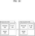
- FIG. 18 is a block diagram of a wireless apparatus in which the embodiments of the present invention is implemented.
- a base station 100 includes a processor 110, a memory 120 and a radio frequency (RF) unit 130.
- the processor 110 implements the proposed functions, processed, and/or methods. For example, the processor 110 configures a plurality of serving cells that use the different frame structures with each other to a UE, and transmits data that requires an ACK/NACK response through each of the serving cells. At the moment, among M DL subframes which are connected to the UL subframe in which the ACK/NACK is transmitted, only four or less DL subframes may actually perform scheduling.
- the memory 120 is connected to the processor 110 and configured to store various information used for the operations for the processor 110.
- the RF unit 130 is connected to the processor 110 and configured to transmit and/or receive a radio signal.
- a UE 200 includes a processor 210, a memory 220, and a RF unit 230.
- the processor 210 implements the proposed functions, processed, and/or methods.
- the processor 210 may receive the configuration of a first serving cell and a second serving cell that use different frame structures with each other, receive data in the DL subframe of the second serving cell, and transmit the ACK/NACK signal in response to the data in the UL subframe of the first serving cell.
- the UL subframe may be determined based on the ACK/NACK timing of the first serving cell or the ACK/NACK timing of the second serving cell.
- the ACK/NACK transmission technique a technique which is defined in aggregating among the FDD cells or a technique which is defined in aggregating among the TDD cells may be used, and the transmission technique may be changed depending on whether only the ACK/NACK for the received data from the first serving cell in the UL subframe in which the ACK/NACK is transmitted or the ACK/NACK for the received data from the first serving cell and the second serving cell is transmitted.
- the processor 110, 210 may include Application-Specific Integrated Circuits (ASICs), other chipsets, logic circuits, data processing devices and/or converters for mutually converting baseband signals and radio signals.
- the memory 120, 220 may include Read-Only Memory (ROM), Random Access Memory (RAM), flash memory, memory cards, storage media and/or other storage devices.
- the RF unit 130, 230 may include one or more antennas for transmitting and/or receiving radio signals.
- the above-described scheme may be implemented as a module (process, function, etc.) for performing the above-described function.
- the module may be stored in the memory 120, 220 and executed by the processor 110, 210.
- the memory 120, 220 may be placed inside or outside the processor 110, 210 and connected to the processor 110, 210 using a variety of well-known means.
Description
- The present invention relates to wireless communications, and more particularly, to a method and apparatus for transmitting a reception acknowledgement for a hybrid automatic repeat request (HARQ) in a wireless communication system in which serving cells using a radio frame of different types with each other are aggregated.
- Long Term Evolution (LTE) based on 3rd Generation Partnership Project (3GPP) Technical Specification (TS)
Release 8 is the leading next-generation mobile communication standard. - As disclosed in 3GPP TS 36.211 V8.7.0 (2009-05) "Evolved Universal Terrestrial Radio Access (E-UTRA); Physical Channels and Modulation (Release 8)", in LTE, a physical channel can be divided into a Physical Downlink Shared Channel (PDSCH) and a Physical Downlink Control Channel (PDCCH), that is, downlink channels, and a Physical Uplink Shared Channel (PUSCH) and a Physical Uplink Control Channel (PUSCH), that is, uplink channels.
- A PUCCH is an uplink control channel used to send uplink control information, such as a Hybrid Automatic Repeat reQuest (HARQ), an acknowledgement/not-acknowledgement (ACK/NACK) signal, a Channel Quality Indicator (CQI), and a Scheduling Request (SR).
- Meanwhile, 3GPP LTE-Advanced (A) that is the evolution of 3GPP LTE is in progress. Technology introduced into 3GPP LTE-A includes a carrier aggregation.
- A carrier aggregation uses a plurality of component carriers. A component carrier is defined by the center frequency and a bandwidth. One downlink component carrier or a pair of an uplink component carrier and a downlink component carrier correspond to one cell. It can be said that a terminal being served using a plurality of downlink component carriers is being served from a plurality of serving cells.
- A time division duplex (TDD) system uses the same frequency in downlink and uplink cases. Therefore, one or more downlink subframes are associated with an uplink subframe. The 'association' implies that transmission/reception in the downlink subframe is associated with transmission/reception in the uplink subframe. For example, when a transmission block is received in a plurality of downlink subframes, a user equipment transmits HARQ ACK/NACK (hereinafter, ACK/NACK) for the transmission block in the uplink subframe associated with the plurality of downlink subframes. At the moment, a minimum time is required to transmit the ACK/NACK. This is because a time for processing the transmission block and a time for generating ACK/NACK are required.
- A frequency division duplex (FDD) system uses different frequencies in downlink and uplink cases. The uplink subframe and the downlink subframe have the relationship of 1:1. In this case, the ACK/NACK for the transmission block which is received in the downlink subframe is transmitted in the uplink subframe after four subframes.
- Meanwhile, in a next generation wireless communication system, a serving cell that uses the TDD and a serving cell that uses the FDD may be aggregated. That is, a plurality of serving cells that use a radio frame of different types with each other may be allocated to a user equipment. In this case, it is problematic in which way the ACK/NACK is transmitted.
- In "Control Channel Design for Carrier Aggregation between LTE FDD and LTE TDD Systems", IEEE 75th Vehicular Technology Conference, Yokohama, Japan, 6-9 May 2012, ISBN 978-1-4673-0989-9, pages 1-5, Yong Li, et al. propose carrier aggregation between FDD and TDD carriers in order to utilize FDD and TDD spectrums more efficiently. Carrier aggregation between FDD and TDD carriers is also discussed in
WO 2012/124980 A1 . - The present invention provides a method and apparatus for transmitting ACK/NACK in a wireless communication system in which serving cells using a radio frame of different types with each other are aggregated.
- In one aspect, a method for transmitting an acknowledgement/not-acknowledgement (ACK/NACK) for a user equipment which has been configured with a plurality of serving cells is provided in accordance with
claim 1. Embodiments of the method are further defined in claims 2-8. - In another aspect, an apparatus of transmitting an acknowledgement/not-acknowledgement (ACK/NACK) for a user equipment which has been configured with a plurality of serving cells is provided in accordance with
claim 9. - In a wireless communication system in which serving cells using a radio frame of different types with each other are aggregated, a user equipment can effectively transmit ACK/NACK. Accordingly, the system performance is increased.
-
-
FIG. 1 shows the structure of an FDD radio frame. -
FIG. 2 shows the structure of a TDD radio frame. -
FIG. 3 shows an example of a resource grid for one downlink slot. -
FIG. 4 shows the structure of a DL subframe. -
FIG. 5 shows the structure of an UL subframe. -
FIG. 6 shows the channel structure of a PUCCH format 1b in a normal CP. -
FIG. 7 shows the channel structure ofPUCCH formats 2/2a/2b in a normal CP. -
FIG. 8 illustrates the channel structure of aPUCCH format 3. -
FIG. 9 shows an example of a comparison between a single carrier system and a carrier aggregation system. -
FIG. 10 shows one example in which a plurality of serving cells uses different types of radio frames in a wireless communication system. -
FIG. 11 shows a method of transmitting ACK/NACK for downlink data received through a primary cell. -
FIG. 12 shows a method of transmitting ACK/NACK for downlink data received through a secondary cell. -
FIG. 13 shows an example of ACK/NACK transmission timing when a primary cell is an FDD cell and a secondary cell is a TDD cell. -
FIG. 14 shows an ACK/NACK transmission method based onMethod 1. -
FIG. 15 shows another example of ACK/NACK transmission timing when a primary cell is an FDD cell and a secondary cell is a TDD cell. -
FIG. 16 shows an ACK/NACK transmission method based onMethod 2. -
FIG. 17 shows an ACK/NACK transmission method according to an embodiment of the present invention. -
FIG. 18 is a block diagram of a wireless apparatus in which the embodiments of the present invention is implemented. - User Equipment (UE) can be fixed or can have mobility. UE can also be called another term, such as a Mobile Station (MS), a Mobile Terminal (MT), a User Terminal (UT), a Subscriber Station (SS), a wireless device, a Personal Digital Assistant (PDA), a wireless modem, or a handheld device.
- The BS commonly refers to a fixed station that communicates with UE. The BS can also be called another tem, such as an evolved-NodeB (eNodeB), a Base Transceiver System (BTS), or an access point.
- Communication from a BS to UE is called downlink (DL), and communication from UE to a BS is called uplink (UL). A wireless communication system including a BS and UE can be a Time Division Duplex (TDD) system or a Frequency Division Duplex (FDD) system. A TDD system is a wireless communication system that performs UL and DL transmission/reception using different times in the same frequency band. An FDD system is a wireless communication system that enables UL and DL transmission/reception at the same time using different frequency bands. A wireless communication system can perform communication using radio frames.
-
FIG. 1 shows the structure of an FDD radio frame. - The FDD radio frame includes 10 subframes, and one subframe includes two consecutive slots. The slots within the radio frame are assigned
indices 0∼19. The time that is taken for one subframe to be transmitted is called a Transmission Time Interval (TTI). A TTI can be a minimum scheduling unit. For example, the length of one subframe can be 1 ms, and the length of one slot can be 0.5 ms. Hereinafter, the FDD radio frame may be simply referred to as an FDD frame. -
FIG. 2 shows the structure of a TDD radio frame. - Referring to
FIG. 2 , a downlink (DL) subframe and an uplink (UL) subframe coexist in a TDD radio frame used in TDD. Table 1 shows an example of a UL-DL configuration of the radio frame.[Table 1] Uplink-downlink configuration Downlink-to-uplink switch-point periodicity Subframe n 0 1 2 3 4 5 6 7 8 9 0 5 ms D S U U U D S U U U 1 5 ms D S U U D D S U U U 2 5 ms D S U D D D S U D D 3 10 ms D S U U U D D D D D 4 10 ms D S U U D D D D D D 5 10 ms D S U D D D D D D D 6 5 ms D S U U U D S U U D - In Table 1, 'D' indicates a DL subframe, 'U' indicates a UL subframe, and 'S' indicates a special subframe. When a UL-DL configuration is received from a BS, a UE can be aware of whether each subframe in a radio frame is a DL subframe or a UL subframe. Hereinafter, reference can be made to Table 1 for a UL-DL configuration N (N is any one of 0 to 6).
- In the TDD frame, a subframe having an
index # 1 and anindex # 6 may be a special subframe, and includes a downlink pilot time slot (DwPTS), a guard period (GP), and an uplink pilot time slot (UpPTS). The DwPTS is used in initial cell search, synchronization, or channel estimation in UE. The UpPTS is used for channel estimation in a BS and for the uplink transmission synchronization of UE. The GP is an interval in which interference occurring in UL due to the multi-path delay of a DL signal between UL and DL is removed. Hereinafter, the TDD radio frame may be simply referred to as a TDD frame. -
FIG. 3 shows an example of a resource grid for one downlink slot. - Referring to
FIG. 3 , the downlink slot includes a plurality of Orthogonal Frequency Division Multiplexing (OFDM) symbol in the time domain and includes NRB Resource Blocks (RBs) in the frequency domain. The RBs includes one slot in the time domain and a plurality of consecutive subcarrier in the frequency domain in a resource allocation unit. The number of RBs NRB included in the downlink slot depends on a downlink transmission bandwidth NDL configured in a cell. For example, in an LTE system, the NRB can be any one of 6 to 110. An uplink slot can have the same structure as the downlink slot. - Each element on the resource grid is called a Resource Element (RE). The RE on the resource grid can be identified by an index pair (k,l) within a slot. Here, k (k=0, ..., NRB ×12-1) is a subcarrier index within the frequency domain, and 1 (1=0,..., 6) is an OFDM symbol index within the time domain.
- Although 7×12 REs including 7 OFDM symbols in the time domain and 12 subcarrier in the frequency domain have been illustrated as being included in one RB in
FIG. 3 , the number of OFDM symbols and the number of subcarriers within an RB are not limited thereto. The number of OFDM symbols and the number of subcarriers can be changed in various ways depending on the length of a CP, frequency spacing, etc. In one OFDM symbol, one of 128, 256, 512, 1024, 1536, and 2048 can be selected and used as the number of subcarriers. -
FIG. 4 shows the structure of a DL subframe. - Referring to
FIG. 4 , a downlink (DL) subframe is divided into a control region and a data region in the time domain. The control region includes a maximum of former 3 (maximun 4 according to circumstances) OFDM symbols of a first slot within a subframe, but the number of OFDM symbols included in the control region can be changed. A control channel different from a physical downlink control channel (PDCCH) is allocated to the control region, and a physical downlink shared channel (PDSCH) is allocated to the data region. - As disclosed in 3GPP TS 36.211 V8.7.0, in 3GPP LTE, physical channels can be divided into a physical downlink shared channel (PDSCH) and a physical uplink shared channel (PUSCH), that is, data channels, and a physical downlink control channel (PDCCH), a physical control format indicator channel (PCFICH), a physical hybrid-ARQ indicator channel (PHICH), and a physical uplink control channel (PUCCH), that is, control channels.
- A PCFICH that is transmitted in the first OFDM symbol of a subframe carries a Control Format Indicator (CFI) regarding the number of OFDM symbols (i.e., the size of a control region) that are used to send control channels within the subframe. UE first receives a CFI on a PCFICH and then monitors PDCCHs. Unlike in a PDCCH, a PCFICH is not subject to blind decoding, but is transmitted through the fixed PCFICH resources of a subframe.
- A PHICH carries a positive-acknowledgement (ACK)/negative-acknowledgement (NACK) signal for an uplink Hybrid Automatic Repeat reQuest (HARQ). An ACK/NACK signal for uplink (UL) data on a PUSCH which is transmitted by UE is transmitted on a PHICH.
- A physical broadcast channel (PBCH) is transmitted in the former 4 OFDM symbols of a second slot within the first subframe of a radio frame. The PBCH carries system information that is essential for UE to communicate with a BS, and system information transmitted through a PBCH is called a Master Information Block (MIB). In contrast, system information transmitted on a PDSCH indicated by a PDCCH is called a System Information Block (SIB).
- Control information transmitted through a PDCCH is called Downlink Control Information (DCI). DCI can include the resource allocation of a PDSCH (this is also called a DL grant), the resource allocation of a PUSCH (this is also called an UL grant), a set of transmit power control commands for individual MSs within a specific UE group and/or the activation of a Voice over Internet Protocol (VoIP).
-
FIG. 5 shows the structure of an UL subframe. - Referring to
FIG. 5 , the UL subframe can be divided into a control region to which a physical uplink control channel (PUSCH) for carrying uplink control information is allocated and a data region to which a physical uplink shared channel (PUSCH) for carrying user data is allocated in the frequency domain. - A PUCCH is allocated with an RB pair in a subframe. RBs that belong to an RB pair occupy different subcarriers in a fist slot and a second slot. An RB pair has the same RB index m.
- In accordance with 3GPP TS 36.211 V8.7.0, a PUCCH supports multiple formats. A PUCCH having a different number of bits in each subframe can be used according to a modulation scheme that is dependent on a PUCCH format.
- Table 2 below shows an example of modulation schemes and the number of bits per subframe according to PUCCH formats.
[Table 2] PUCCH format Modulation scheme Number of bits per subframe 1 N/A N/ A 1a BPSK 1 1b QPSK 2 2 QPSK 20 2a QPSK+BPSK 21 2b QPSK+QPSK 22 - The
PUCCH format 1 is used to send a Scheduling Request (SR), the PUCCH formats 1a/1b are used to send an ACK/NACK signal for an HARQ, thePUCCH format 2 is used to send a CQI, and the PUCCH formats 2a/2b are used to send a CQI and an ACK/NACK signal at the same time. When only an ACK/NACK signal is transmitted in a subframe, the PUCCH formats 1a/1b are used. When only an SR is transmitted, thePUCCH format 1 is used. When an SR and an ACK/NACK signal are transmitted at the same time, thePUCCH format 1 is used. In this case, the ACK/NACK signal is modulated into resources allocated to the SR and is then transmitted. - All the PUCCH formats use the Cyclic Shift (CS) of a sequence in each OFDM symbol. A CS sequence is generated by cyclically shifting a base sequence by a specific CS amount. The specific CS amount is indicated by a CS index.
- An example in which a base sequence ru(n) has been defined is the same as the following equation.

- Here, u is a root index, n is an element index wherein 0≤n≤N-1, and N is the length of the base sequence. b(n) is defined in section 5.5 of 3GPP TS 36.211 V8.7.0.
- The length of a sequence is the same as the number of elements included in the sequence. U can be determined by a cell identifier (ID), a slot number within a radio frame, etc.
- Assuming that a base sequence is mapped to one resource block in the frequency domain, the length N of the base sequence becomes 12 because one resource block includes 12 subcarriers. A different base sequence is defined depending on a different root index.
- A CS sequence r(n, Ics) can be generated by cyclically shifting the base sequence r(n) as in
Equation 2.
- Here, Ics is a CS index indicative of a CS amount (0≤Ics≤N-1).
- An available CS index of a base sequence refers to a CS index that can be derived from the base sequence according to a CS interval. For example, the length of a base sequence is 12 and a CS interval is 1, a total number of available CS indices of the base sequence becomes 12. Or, if the length of a base sequence is 12 and a CS interval is 2, a total number of available CS indices of the base sequence becomes 6.
-
FIG. 6 shows the channel structure of the PUCCH format 1b in a normal CP. - One slot includes 7 OFDM symbols, the 3 OFDM symbols become Reference Signal (RS) OFDM symbols for a reference signal, and the 4 OFDM symbols become data OFDM symbols for an ACK/NACK signal.
- In the PUCCH format 1b, a modulation symbol d(0) is generated by performing Quadrature Phase Shift Keying (QPSK) modulation on an encoded 2-bit ACK/NACK signal.
- A CS index Ics can vary depending on a slot number 'ns' within a radio frame and/or a symbol index '1' within a slot.
- In a normal CP, 4 data OFDM symbols for sending an ACK/NACK signal are present in one slot. It is assumed that corresponding CS indices in respective data OFDM symbols are Ics0, Ics1, Ics2, and Ics3.
- The modulation symbol d(0) is spread into a CS sequence r(n,Ics). Assuming that a 1-dimensional spread sequence corresponding to an (i+1)th OFDM symbol is m(i) in a slot,
- {m(0), m(1), m(2), m(3)} = {d(0)r(n,Ics0), d(0)r(n,Ics1), d(0)r(n,Ics2), d(0)r(n,Ics3)} can be obtained.
- In order to increase a UE capacity, the 1-dimensional spread sequence can be spread using an orthogonal sequence. The following sequence is used as an orthogonal sequence wi(k) (i is a sequence index, 0≤k≤K-1) wherein a spreading factor K=4.
[Table 3] Index (i) [wi(0), wi(1), wi(2), wi(3)] 0 [+1, +1, +1, +1] 1 [+1, -1, 1, -1] 2 [+1, -1, -1, +1] - The following sequence is used as an orthogonal sequence wi(k) (i is a sequence index, 0≤k≤K-1) wherein a spreading factor K=3.
[Table 4] Index (i) [wi(0), wi(1), wi(2)] 0 [+1, +1, +1] 1 [+1, ej2π/3, ej4π/3] 2 [+1, ej4π/3, ej2π/3] - A different spreading factor can be used in each slot.
- Accordingly, assuming that a specific orthogonal sequence index i is given, 2-dimensional spread sequences {s(0), s(1), s(2), s(3)} can be expressed as follows.

- The 2-dimensional spread sequences {s(0), s(1), s(2), s(3)} are subject to IFFT and then transmitted in a corresponding OFDM symbol. Accordingly, an ACK/NACK signal is transmitted on a PUCCH.
- A reference signal having the PUCCH format 1b is also transmitted by spreading the reference signal into an orthogonal sequence after cyclically shifting a base sequence r(n). Assuming that CS indices corresponding to 3 RS OFDM symbols are Ics4, Ics5, and Ics6, 3 CS sequences r(n,Ics4), r(n,Ics5), r(n,Ics6) can be obtained. The 3 CS sequences are spread into an orthogonal sequence wRS i(k) wherein K=3.
- An orthogonal sequence index i, a CS index Ics, and an RB index m are parameters necessary to configure a PUCCH and are also resources used to classify PUCCHs (or MSs). If the number of available CSs is 12 and the number of available orthogonal sequence indices is 3, a PUCCH for a total of 36 MSs can be multiplexed with one RB.
- In 3GPP LTE, a resource index n(1) PUCCH is defined so that UE can obtain the three parameters for configuring a PUCCH. The resource index n(1) PUCCH = nccE + N(1) PUCCH, wherein nCCE is the number of the first CCE used to send a corresponding PDCCH (i.e., PDCCH including the allocation of DL resources used to received downlink data corresponding to an ACK/NACK signal), and N(1) PUCCH is a parameter that is informed of UE by a BS through a higher layer message.
- Time, frequency, and code resources used to send an ACK/NACK signal are called ACK/NACK resources or PUCCH resources. As described above, an index of ACK/NACK resources (called an ACK/NACK resource index or PUCCH index) used to send an ACK/NACK signal on a PUCCH can be represented as at least one of an orthogonal sequence index i, a CS index Ics, an RB index m, and an index for calculating the 3 indices. ACK/NACK resources can include at least one of an orthogonal sequence, a CS, a resource block, and a combination of them.
-
FIG.7 shows the channel structure of the PUCCH formats 2/2a/2b in a normal CP. - Referring to
FIG. 7 , in a normal CP,OFDM symbols 1 and 5 (i.e., second and sixth OFDM symbols) are used to send a demodulation reference signal (DM RS),t hat is, an uplink reference signal, and the remaining OFDM symbols are used to send a CQI. In the case of an extended CP, an OFDM symbol 3 (fourth symbol) is used for a DM RS. - 10 CQI information bits can be subject to channel coding at a 1/2 code rate, for example, thus becoming 20 coded bits. Reed-Muller code can be used in the channel coding. Next, the 20 coded bits are scramble and then subject to QPSK constellation mapping, thereby generating a QPSK modulation symbol (d(0) to d(4) in a slot 0). Each QPSK modulation symbol is modulated in a cyclic shift of a base RS sequence 'r(n)' having a length of 12, subject to IFFT, and then transmitted in each of 10 SC-FDMA symbols within a subframe. Uniformly spaced 12 CSs enable 12 different MSs to be orthogonally multiplexed in the same PUCCH RB. Abase RS sequence 'r(n)' having a length of 12 can be used as a DM RS sequence applied to
OFDM symbols -
FIG. 8 shows an example of a channel structure of aPUCCH format 3. - Referring to
FIG. 8 , thePUCCH format 3 is a PUCCH format which uses a block spreading scheme. The block spreading scheme means a method of spreading a symbol sequence, which is obtained by modulating a multi-bit ACK/NACK, in a time domain by using a block spreading code. - In the
PUCCH format 3, a symbol sequence (e.g., ACK/NACK symbol sequence) is transmitted by being spread in the time domain by using the block spreading code. An orthogonal cover code (OCC) may be used as the block spreading code. Control signals of several UEs may be multiplexed by the block spreading code. In thePUCCH format 2, a symbol (e.g., d(0), d(1), d(2), d(3), d(4), etc., ofFIG. 7 ) transmitted in each data symbol is different, and UE multiplexing is performed using the cyclic shift of a constant amplitude zero auto-correlation (CAZAC) sequence. In contrast, in thePUCCH format 3, a symbol sequence including one or more symbols is transmitted in a frequency domain of each data symbol, the symbol sequence is spread in a time domain by using the block spreading code, and UE multiplexing is performed. An example in which 2 RS symbols are used in one slot has been illustrated inFIG. 8 , but the present invention is not limited thereto. 3 RS symbols may be used, and an OCC having a spreading factor value of 4 may be used. An RS symbol may be generated from a CAZAC sequence having a specific cyclic shift and may be transmitted in such a manner that a plurality of RS symbols in the time domain has been multiplied by a specific OCC. - Now, a carrier aggregation system is described. The carrier aggregation system is also called a multiple carrier system.
- A 3GPP LTE system supports a case where a DL bandwidth and a UL bandwidth are differently configured, but one component carrier (CC) is a precondition in this case. A 3GPP LTE system supports a maximum of 20 MHz and may be different in a UL bandwidth and a DL bandwidth, but supports only one CC in each of UL and DL
- A carrier aggregation (also called a bandwidth aggregation or a spectrum aggregation) supports a plurality of CCs. For example, if 5 CCs are allocated as the granularity of a carrier unit having a 20 MHz bandwidth, a maximum of a 100 MHz bandwidth may be supported.
-
FIG. 9 shows an example of a comparison between a single carrier system and a carrier aggregation system. - A carrier aggregation system (
FIG. 9(b) ) has been illustrated as including three DL CCs and three UL CCs, but the number of DL CCs and UL CCs is not limited. A PDCCH and a PDSCH may be independently transmitted in each DL CC, and a PUCCH and a PUSCH may be independently transmitted in each UL CC. Or, a PUCCH may be transmitted only through a specific UL CC. - Since three pairs of DL CCs and UL CCs are defined, it can be said that a UE is served from three serving cells. Hereinafter, a cell which is configured to provide a service to a user equipment is referred to a serving cell.
- The UE may monitor PDCCHs in a plurality of DL CCs and receive DL transport blocks through the plurality of DL CCs at the same time. The UE may send a plurality of UL transport blocks through a plurality of UL CCs at the same time.
- A pair of a DL CC #A and a UL CC #A may become a first serving cell, a pair of a DL CC #B and a UL CC #B may become a second serving cell, and a DL CC #C and a UL CC#C may become a third serving cell. Each serving cell may be identified by a cell index (CI). The CI may be unique within a cell or may be UE-specific.
- The serving cell may be divided into a primary cell and a secondary cell. The primary cell is a cell on which the UE performs an initial connection establishment procedure or initiates a connection re-establishment procedure, or a cell designated as a primary cell in a handover process. The primary cell is also called a reference cell. The secondary cell may be configured after an RRC connection has been established and may be used to provide additional radio resources. At least one primary cell is always configured, and a secondary cell may be added/modified/released in response to higher layer signaling (e.g., an RRC message). The CI of the primary cell may be fixed. For example, the lowest CI may be designated as the CI of the primary cell.
- The primary cell includes a downlink primary component carrier (DL PCC) and an uplink PCC (UL PCC) in view of a CC. The secondary cell includes only a downlink secondary component carrier (DL SCC) or a pair of a DL SCC and a UL SCC in view of a CC. Hereinafter, the term, 'cell' may be mixed with the term 'component carrier (CC)'.
- As described above, the carrier aggregation system may support a plurality of CCs, that is, a plurality of serving cells unlike the single carrier system.
- Such a carrier aggregation system may support cross-carrier scheduling. The cross-carrier scheduling is a scheduling method capable of performing resource allocation of a PDSCH transmitted through a different component carrier through a PDCCH transmitted through a specific component carrier and/or resource allocation of a PUSCH transmitted through other component carriers except for a component carrier fundamentally linked with the specific component carrier. That is, the PDCCH and the PDSCH may be transmitted through different DL CCs, and a PUSCH may be transmitted through a UL CC different from a UL CC linked with a DL CC to which a PDCCH including a UL is transmitted. As described above, in a system for supporting the cross-carrier scheduling, the PDCCH needs a carrier indicator indicating that PDSCH/PUSCH are transmitted through a certain DL CC/UL CC. Hereinafter, a field including the carrier indicator refers to a carrier indication field (CIF).
- The carrier aggregation system that supports the cross-carrier scheduling may include a carrier indication field (CIF) to the conventional downlink control information (DCI). In a system that supports the cross-carrier scheduling, for example, LTE-A system, 3 bits may be extended since the CIF is added to the conventional DCI format (i.e., the DCI format used in LTE), and the PDCCH structure may reuse the conventional coding method, resource allocation method (i.e., resource mapping based on the CCE), and the like.
- A BS may set a PDCCH monitoring DL CC (monitoring CC) group. The PDCCH monitoring DL CC group is configured by a part of all aggregated DL CCs. If the cross-carrier scheduling is configured, the UE performs PDCCH monitoring/decoding for only a DL CC included in the PDCCH monitoring DL CC group. That is, the BS transmits a PDCCH with respect to a PDSCH/PUSCH to be scheduled through only the DL CCs included in the PDCCH monitoring DL CC group. The PDCCH monitoring DL CC group may be configured in a UE-specific, UE group-specific, or cell-specific manner.
- Non-cross carrier scheduling (NCSS) is a scheduling method capable of performing resource allocation of a PDSCH transmitted through a specific component carrier through a PDCCH transmitted through the specific component carrier and/or resource allocation of a PDSCH transmitted through a component carrier fundamentally linked with the specific component carrier.
- ACK/NACK transmission for HARQ in 3GPP LTE Time Division Duplex (TDD) is described below.
- In TDD, unlike in a Frequency Division Duplex (FDD), a DL subframe and an UL subframe coexist in one radio frame. In general, the number of UL subframes is smaller than that of DL subframes. Accordingly, in preparation for a case where UL subframes for sending an ACK/NACK signal are not sufficient, a plurality of ACK/NACK signals for DL transport blocks received in a plurality of DL subframes is transmitted in one UL subframe.
- In accordance with section 10.1 of 3GPP TS 36.213 V8.7.0 (2009-05), two ACK/NACK modes: ACK/NACK bundling and ACK/NACK multiplexing are initiated.
- In ACK/NACK bundling, UE sends ACK if it has successfully decoded all received PDSCHs (i.e., DL transport blocks) and sends NACK in other cases. To this end, ACK or NACKs for each PDSCH are compressed through logical AND operations.
- ACK/NACK multiplexing is also called ACK/NACK channel selection (or simply channel selection). In accordance with ACK/NACK multiplexing, UE selects one of a plurality of PUCCH resources and sends ACK/NACK.
- Table below shows DL subframes n-k associated with an UL subframe n according to an UL-DL configuration in 3GPP LTE, wherein k∈K and M is the number of elements of a set K.
[Table 5] UL-DL Configuration Subframe n 0 1 2 3 4 5 6 7 8 9 0 - - 6 - 4 - - 6 - 4 1 - - 7, 6 4 - - - 7, 6 4 - 2 - - 8, 7, 4, 6 - - - - 8, 7, 4, 6 - - 3 - - 7, 6, 11 6, 5 5, 4 - - - - - 4 - - 12, 8, 7, 11 6, 5, 4, 7 - - - - - - 5 - - 13, 12, 9, 8, 7, 5, 4, 11, 6 - - - - - - - 6 - - 7 7 5 - - 7 7 - - It is assumed that M DL subframes are associated with the UL subframe n and, for example, M=3. In this case, UE can obtain 3 PUCCH resources n(1) PUCCH,0, n(1) PUCCH,1, and n(1) PUCCH,2 because it can receive 3 PDCCHs from 3 DL subframes. In this case, an example of ACK/NACK channel selection is the same as the following table.
[Table 6] HARQ-ACK(0),HARQ-ACK(1),HARQ-ACK(2) n(1) PUCCH b(0),b(1) ACK, ACK, ACK n (1) PUCCH,2 1,1 ACK, ACK, NACK/ DTX n (1) PUCCH,1 1,1 ACK, NACK/DTX, ACK n (1) PUCCH,0 1,1 ACK, NACK/DTX, NACK/ DTX n (1) PUCCH,0 0,1 NACK/DTX, ACK, ACK n (1) PUCCH,2 1,0 NACK/DTX, ACK, NACK/ DTX n (1) PUCCH,1 0,0 NACK/DTX, NACK/DTX, ACK n (1) PUCCH,2 0,0 DTX, DTX, NACK n (1) PUCCH,2 0,1 DTX, NACK, NACK/ DTX n (1) PUCCH,1 1,0 NACK, NACK/DTX, NACK/ DTX n (1) PUCCH,0 1,0 DTX, DTX, DTX N/A N/A - In the above table, HARQ-ACK(i) indicates ACK/NACK for an ith DL subframe of M DL subframes. Discontinuous transmission (DTX) means that a DL transport block has not been received on a PDSCH in a corresponding DL subframe or that a corresponding PDCCH has not been detected. In accordance with Table 6, 3 PUCCH resources n(1) PUCCH,0, n(1) PUCCH,1, and n(1) PUCCH,2 are present, and b(0), b(1) are two bits transmitted using a selected PUCCH.
- For example, when UE successfully receives all 3 DL transport blocks in 3 DL subframes, the UE performs QPSK modulation on bits (1,1) using n(1) PUCCH,2 and sends them on a PUCCH. If UE fails in decoding a DL transport block in a first (i=0) DL subframe, but succeeds in decoding the remaining transport blocks, the UE sends bits (1,0) on a PUCCH using n(1) PUCCH,2. That is, in the existing PUCCH format 1b, only ACK/NACK of 2 bits can be transmitted. However, in channel selection, allocated PUCCH resources are linked to an actual ACK/NACK signal in order to indicate more ACK/NACK states. This channel selection is also referred to as channel selection using the PUCCH format 1b.
- In ACK/NACK channel selection, if at least one ACK is present, NACK and DTX are coupled. This is because all ACK/NACK states cannot be represented by a combination of reserved PUCCH resources and a QPSK symbol. If ACK is not present, however, DTX is decoupled from NACK.
- The above-described ACK/NACK bundling and ACK/NACK multiplexing can be applied in the case where one serving cell has been configured in UE in TDD.
- For example, it is assumed that one serving cell has been configured (i.e., only a primary cell is configured) in UE in TDD, ACK/NACK bundling or ACK/NACK multiplexing is used, and M=1. That is, it is assumed that one DL sub frame is associated with one UL subframe.
- 1) UE sends ACK/NACK in a subframe n if the UE detects a PDSCH indicated by a corresponding PDCCH in a subframe n-k of a primary cell or detects a Semi-Persistent Scheduling (SPS) release PDCCH. In LTE, a BS can inform UE that semi-persistent transmission and reception are performed in what subframes through a higher layer signal, such as Radio Resource Control (RRC). Parameters given by the higher layer signal can be, for example, the periodicity of a subframe and an offset value. When the UE receives the activation or release signal of SPS transmission through a PDCCH after recognizing semi-persistent transmission through the RRC signaling, the UE performs or releases SPS PDSCH reception or SPS PUSCH transmission. That is, the UE does not immediately perform SPS transmission/reception although SPS scheduling is allocated thereto through the RRC signaling, but when an activation or release signal is received through a PDCCH, performs SPS transmission/reception in a subframe that corresponds to frequency resources (resource block) according to the allocation of the resource block designated by the PDCCH, modulation according to MCS information, a subframe periodicity allocated through the RRC signaling according to a code rate, and an offset value. Here, a PDCCH that releases SPS is called an SPS release PDCCH, and a DL SPS release PDCCH that releases DL SPS transmission requires the transmission of an ACK/NACK signal.
- Here, in the subframe n, UE sends ACK/NACK using the PUCCH formats 1a/1b according to a PUCCH resource n(1,p) PUCCH. In n(1,p) PUCCH, p indicates an antenna port p. The k is determined by Table 5.
- The PUCCH resource n(1,p) PUCCH can be allocated as in the following equation. P can be p0 or p1.

- In
Equation 3, c is selected in such a way as to satisfy Nc ≤ nccE < Nc+1(antenna port p0), Nc ≤ (nCCE + 1) < Nc+1(antenna port p1) from among {0,1,2,3}. N(1) PUCCH is a value set by a higher layer signal. Nc = max {0, floor [NDL RB · (NRBsc · c - 4)/36]}. The NDL RB is a DL bandwidth, and NRB sc is the size of an RB indicated by the number of subcarriers in the frequency domain. nCCE is a first CCE number used to send a corresponding PDCCH in a subframe n-km. m is a value that makes km the smallest value in the set K of Table 5. - 2) If UE detects an SPS PDSCH, that is, a PDSCH not including a corresponding PDCCH, in the DL subframe n-k of a primary cell, the UE can send ACK/NACK in the subframe n using the PUCCH resource n(1,p) PUCCH as follows.
- Since an SPS PDSCH does not include a scheduling PDCCH, UE sends ACK/NACK through the PUCCH formats 1a/1b according to n(1,p) PUCCH that is configured by a higher layer signal. For example, 4 resources (a first PUCCH resource, a second PUCCH resource, a third PUCCH resource, and a fourth PUCCH resource) can be reserved through an RRC signal, and one resource can be indicated through the Transmission Power Control (TPC) field of a PDCCH that activates SPS scheduling.
- The following table is an example in which resources for channel selection are indicated by a TPC field value.
[Table 7] TPC field value Resource for channel selection '00' First PUCCH resource '01' Second PUCCH resource '10' Third PUCCH resource '11' Fourth PUCCH resource - For another example, it is assumed that in TDD, one serving cell is configured (i.e., only a primary cell is configured) in UE, ACK/NACK multiplexing is used, and M>1. That is, it is assumed that a plurality of DL subframes is associated with one UL subframe.
- 1) A PUCCH resource n(1) PUCCH,i for sending ACK/NACK when UE receives a PDSCH in a subframe n-ki (0≤i≤M-1) or detects a DL SPS release PDCCH can be allocated as in the following equation. Here, ki∈K, and the set K has been described with reference to Table 5.
- Here, c is selected from {0,1,2,3} so that Nc≤nCCE,i < Nc+1 is satisfied. N(1) PUCCH is a value set by a higher layer signal. NC = max{0, floor [NDL RB · (NRB sc · c - 4)/36]}. The NDL RB is a DL bandwidth, and NRB sc is the size of an RB indicated by the number of subcarriers in the frequency domain. nCCE,i is a first CCE number used to send a corresponding PDCCH in the subframe n - ki.
- 2) If UE receives a PDSCH (i.e., SPS PDSCH) not having a corresponding PDCCH in the subframe, n(1) PUCCH,i is determined by a configuration given by a higher layer signal and Table 7.
- If two or more serving cells have been configured in UE in TDD, the UE sends ACK/NACK using channel selection that uses the PUCCH format 1b or the
PUCCH format 3. Channel selection that uses the PUCCH format 1b used in TDD can be performed as follows. - If a plurality of serving cells using channel selection that uses the PUCCH format 1b has been configured, when ACK/NACK bits are greater than 4 bits, UE performs spatial ACK/NACK bundling on a plurality of codewords within one DL subframe and sends spatially bundled ACK/NACK bits for each serving cell through channel selection that uses the PUCCH format 1b. Spatial ACK/NACK bundling means the compression of ACK/NACK for each codeword through logical AND operations within the same DL subframe.
- If ACK/NACK bits are 4 bits or lower, spatial ACK/NACK bundling is not used and the ACK/NACK bits are transmitted through channel selection that uses the PUCCH format 1b.
- If 2 or more serving cells using the
PUCCH format 3 have been configured in UE, when ACK/NACK bits are greater than 20 bits, spatial ACK/NACK bundling can be performed in each serving cell and ACK/NACK bits subjected to spatial ACK/NACK bundling can be transmitted through thePUCCH format 3. If ACK/NACK bits are 20 bits or lower, spatial ACK/NACK bundling is not used and the ACK/NACK bits are transmitted through thePUCCH format 3. - If two serving cells using FDD have been configured in UE, ACK/NACK can be transmitted through channel selection that uses the PUCCH format 1b. The UE can feed ACK/NACK for a maximum of 2 transport blocks, received in one serving cell, back to a BS by sending 2-bit (b(0)b(1)) information in one PUCCH resource selected from a plurality of PUCCH resources. One codeword can be transmitted in one transport block. A PUCCH resource can be indicated by a resource index n(1) PUCCH,i. Here, A is any one of {2, 3, 4}, and i is 0≤i≤(A-1). The 2-bit information is indicated as b(0)b(1).
- HARQ-ACK(j) indicates an HARQ ACK/NACK response that is related to a transport block or DL SPS release PDCCH transmitted by a serving cell. The HARQ-ACK(j), the serving cell, and the transport block can have the following mapping relationship.
[Table 8] A HARQ-ACK(j) HARQ-ACK(0) HARQ-ACK(1) HARQ-ACK(2) HARQ-ACK(3) 2 Transport block 1 of primarycell Transport block 2 of secondary cell NA NA 3 Transport block 1 of servingcell 1Transport block 2 of servingcell 1Transport block 3 of servingcell 2NA 4 Transport block 1 of primarycell Transport block 2 of primary cell Transport block 3 of secondary cell Transport block 4 of secondary cell - In Table 8, for example, in the case of A=4, HARQ-ACK(0) and HARQ-ACK(1) indicate ACK/NACKs for 2 transport blocks transmitted in a primary cell, and HARQ-ACK(2) and HARQ-ACK(3) indicate ACK/NACKs for 2 transport blocks transmitted in a secondary cell.
- When UE receives a PDSCH or detects a DL SPS release PDCCH by detecting a PDCCH in a subframe 'n-4' of a primary cell, the UE sends ACK/NACK using a PUCCH resource n(1) PUCCH,i. Here, n(1) PUCCH,i is determined to be nCCE,i+N(1) PUCCH. Here, nCCE,i means an index of the first CCE that is used to send a PDCCH by a BS, and N(1) PUCCH is a value set through a higher layer signal. If a transmission mode of a primary cell supports up to two transport blocks, a PUCCH resource n(1) PUCCH,i+1 is given. Here, n(1) PUCCH,i+1 can be determined to be nCCE,i + 1 + N(1) PUCCH. That is, if a primary cell is set in a transmission mode in which a maximum of up to 2 transport blocks can be transmitted, 2 PUCCH resources can be determined.
- If a PDCCH detected in a subframe 'n-4' of a primary cell is not present, a PUCCH resources n(1) PUCCH,i for sending ACK/NACK for a PDSCH is determined by a higher layer configuration. If up to 2 transport blocks are supported, a PUCCH resource n(1) PUCCH,i+1 can be given as n(1) PUCCH,i+1= n(1) PUCCH,i+1.
- If a PDSCH is received in a secondary cell by detecting a PDCCH in a subframe 'n-4', PUCCH resources n(1) PUCCH,i and n(1) PUCCH,i+1 for a transmission mode in which up to 2 transport blocks are supported can be determined by a higher layer configuration.
- Meanwhile, in the prior art, it was a precondition that a plurality of serving cells configured in a UE uses radio frames having the same type. For example, it was a precondition that all of a plurality of serving cells configured in the UE use FDD frames or use TDD frames. In the next-generation wireless communication system, however, different types of radio frames may be used respectively in serving cells.
-
FIG. 10 shows one example in which a plurality of serving cells use different types of radio frames in a wireless communication system. - Referring to
FIG. 10 , a primary cell PCell and a plurality of secondarycells SCell # 1, ... , SCell #N may be configured in a UE. In this case, the primary cell may operate in FDD and use an FDD frame, and the secondary cells may operate in TDD and use TDD frames. The same UL-DL configuration may be used in the plurality of secondary cells. A DL subframe (indicated by D) and a UL subframe (indicated by U) are present in a 1:1 manner in the primary cell, but a DL subframe and a UL subframe may be present in a different ratio other than 1:1 in the secondary cells. - Table 9 below shows that ACK/NACK is transmitted in what a subframe according to a UL-DL configuration when one serving cell operates in TDD. Table 9 is equivalent to Table 5.
[Table 9] UL-DL Configuration Subframe n 0 1 2 3 4 5 6 7 8 9 0 4 6 - 4 6 - 1 7 6 4 7 6 4 2 7 6 4 8 7 6 4 8 3 4 11 7 6 6 5 5 4 12 11 8 7 7 6 5 4 5 12 11 9 8 7 6 5 4 13 6 7 7 7 7 5 - In Table 9, when a UE receives a PDSCH or a PDCCH (e.g., DL SPS release PDCCH) necessary for an ACK/NACK response in a subframe n, the UE sends ACK/NACK in a subframe n + k(n). Each of the values of Table 9 indicates the k(n) value. For example, Table 9 indicates that if a UL-DL configuration is 0 and a PDSCH is received in a
subframe 0, ACK/NACK is transmitted after four subframes elapse, i.e., in asubframe 4. A specific time is necessary in order for the UE to send ACK/NACK after receiving a PDSCH or a DL SPS release PDCCH. A minimum value of this specific time is hereinafter indicated as kmin, and a value of kmin may be four subframes. Four subframes, which is the minimum value of the specific time, are determined by considering a propagation delay between the transmission terminal and the reception terminal, a processing time which is required for decoding at the reception terminal. When looking at the timing of transmitting ACK/NACK in Table 9 above, the ACK/NACK is mainly transmitted in the first uplink subframe after a lapse of kmin. However, the underlined figures do not indicate the first uplink subframe after a lapse of kmin, but indicate the uplink subframe which is located at the next position. The reason for this is to prevent from transmitting the ACK/NACK for too many downlink subframes in one uplink subframe. - Meanwhile, since a UL subframe : DL subframe ratio is always 1:1 in FDD, ACK/NACK timing is determined as shown in the following table.
[Table 9-1] Frame Structure Subframe n 0 1 2 3 4 5 6 7 8 9 FDD 4 4 4 4 4 4 4 4 4 4 - That is, as shown in the above Table, k(n)= kmin =4 for all subframes.
- Meanwhile, in the prior art, it was a precondition that all serving cells use radio frames having the same type, and ACK/NACK transmission timing, that is, HARQ timing, was determined based on this assumption. However, if a plurality of serving cells use different types of radio frames, it is necessary to determine which method will be used to transmit ACK/NACK.
- It is hereinafter assumed that a primary cell and at least one secondary cell are configured in a UE in a wireless communication system. It is also assumed that the primary cell uses an FDD frame and the secondary cell uses a TDD frame. Any one of the UL-DL configurations of Table 1 may be used in the TDD frame. Hereinafter, only a relationship between a primary cell and one secondary cell is illustrated, for convenience of description, but this relationship may be applied to a relationship between a primary cell and each of a plurality of secondary cells when the plurality of secondary cells are configured in the UE.
- Under this assumption, first, a method of transmitting ACK/NACK for downlink data received through a primary cell is described below. Hereinafter, the downlink data generally indicates a PDSCH that requests an ACK/NACK response, a codeword included in a PDSCH, a DL SPS release PDCCH indicating a DL SPS release and the like.
-
FIG. 11 shows a method of transmitting ACK/NACK for downlink data received through a primary cell. - Referring to
FIG. 11 , a BS sends downlink data in a subframe n of a primary cell (S110). From a view of a UE, the downlink data is received in a subframe n of a DL PCC of the primary cell. - The UE decodes the downlink data and generates ACK/NACK for the downlink data (S120).
- The UE sends the ACK/NACK in a subframe n + kPCC(n) of the primary cell (S130).
- The subframe n + kPCC(n) of the primary cell is a subframe after a minimum delay time (this is called kmin) necessary for an ACK/NACK response has elapsed from a point of time at which the downlink data was received. Here, the minimum delay time kmin may be four subframes. Accordingly, the UE may send the ACK/NACK in a subframe n + 4 of a UL PCC of the primary cell.
- That is, in the primary cell, as in the case where an HARQ is performed in conventional FDD, the ACK/NACK is transmitted in a subframe after four subframes elapse from a subframe in which data was received.
- Now, a method of sending ACK/NACK when a UE receives downlink data in a secondary cell is described.
-
FIG. 12 shows a method of transmitting ACK/NACK for downlink data received through a secondary cell. - Referring to
FIG. 12 , a BS sends information about a UL-DL configuration of the secondary cell (S210). The secondary cell may need the UL-DL configuration information because it operates in TDD. The UL-DL configuration information may be transmitted through a higher layer signal, such as an RRC message. - A BS sends downlink data in a subframe n of the secondary cell (S220).
- The UE decodes the downlink data and generates ACK/NACK for the downlink data (S230).
- The UE may send the ACK/NACK to the BS through a subframe n + kscc(n) of a primary cell (S240). The subframe n + kSCC(n) may be determined by the following method.
-
Method 1 is a method in which a subframe n + kSCC(n) complies with ACK/NACK transmission timing in a primary cell. That is,Method 1 is a method of configuring a UL subframe of the primary cell equal to n+kmin as the subframe n + kSCC(n). In other words, if data is received in a subframe n of a secondary cell, ACK/NACK for the data is transmitted in the subframe n + kmin of the primary cell. Here, kmin may be, for example, four subframes. -
FIG. 13 shows an example of ACK/NACK transmission timing when a primary cell is an FDD cell and a secondary cell is a TDD cell. - Referring to
FIG. 13 , it is assumed that a UL subframe of PCC in which ACK/NACK is transmitted for a DL data channel or DL control channel received in a DL subframe n of PCC is a subframe n + kPCC(n). In case of FDD, to avoid an ACK/NACK transmission delay, it may be set to kPCC(n)= kmin =4 similarly in the conventional way. - It is assumed that a UL subframe of PCC in which ACK/NACK is transmitted for a DL data channel or DL control channel received in a DL subframe n of SCC is a subframe n + kscc(n). Then, kscc(n) may comply with ACK/NACK timing of FDD configured in PCC. That is, it may be set to kscc(n)= kmin =4. For example, ACK/NACK for a DL data channel or DL control channel received in a
subframe n 131 of SCC is transmitted in a subframe n+4 132 of PCC. -
FIG. 14 shows an ACK/NACK transmission method based onMethod 1. - Referring to
FIG. 14 , in a situation where a 1st cell and a 2nd cell are aggregated, data requiring ACK/NACK is received in a DL subframe of the 2nd cell (S161). Herein, the data requiring ACK/NACK collectively refers to data requiring an ACK/NACK response such as a PDSCH, a transport block, and a DL SPS release PDCCH. The 1st cell is an FDD cell using an FDD frame, and may be a primary cell. The 2nd cell is a TDD cell using a TDD frame, and may be a secondary cell. - A UE transmits ACK/NACK for the data in a UL subframe of the 1st cell determined according to ACK/NACK timing of the 1st cell (S162).
- In accordance with
Method 1, there is an advantage in that ACK/NACK delay is minimized because ACK/NACK for downlink data received in the secondary cell is always transmitted after kmin subframes elapse on the basis of a point of time at which the downlink data was received. - Furthermore, in conventional TDD, if the number of DL subframes associated with one UL subframe is many, there is a problem in that the number of ACK/NACKs that must be transmitted in the one UL subframe is increased. However,
Method 1 is advantageous in that ACK/NACK transmission is distributed. - If the UL subframe of a primary cell in which ACK/NACK is transmitted is a subframe n, the number of ACK/NACK resources that need to be secured in the subframe n may be determined by a transmission mode of the primary cell for a subframe n - kmin and a transmission mode in a DL subframe of the secondary cell.
- In accordance with
Method 1, ACK/NACK timing applied to the UE may be represented by changing Table 5 into Table 10 below.[Table 10] UL-DL Configuration Subframe n 0 1 2 3 4 5 6 7 8 9 0 4 - - 4 4 - - 4 1 4 - - 4 4 4 - - 4 4 2 4 - 4 4 4 4 - 4 4 4 3 4 4 4 4 4 4 - - - 4 4 4 4 4 4 4 4 - - 4 4 5 4 4 4 4 4 4 - 4 4 4 6 4 - 4 4 4 - 4 - That is, if a UL-DL configuration of the secondary cell is the same as any one of Table 10 and the primary cell uses an FDD frame, a subframe n is a subframe in which ACK/NACK is transmitted and a number indicated in the subframe n indicates kmin. Herein, the subframe n - kmin indicates a subframe in which downlink data, that is, the subject of ACK/NACK, is received. For example, in Table 10, a UL-DL configuration is 0, and 4 is written in a
subframe 9. In this case, it indicates that ACK/NACK for downlink data received in the subframe 5 (=9-4) of the secondary cell is transmitted in thesubframe 9. - In accordance with
Method 1, ACK/NACK timing applied to the UE may be represented by changing Table 9 into Table 11 below.[Table 11] UL-DL Configuration Subframe n 0 1 2 3 4 5 6 7 8 9 0 4 4 - 4 4 - 1 4 4 4 4 4 4 2 4 4 4 4 4 4 4 4 3 4 4 4 4 4 4 4 4 4 4 4 4 4 4 4 4 5 4 4 4 4 4 4 4 4 4 6 4 4 4 4 4 - In Table 11, a subframe n indicates a subframe in which downlink data is received. A subframe n + kSCC(n) is a subframe in which ACK/NACK for the downlink data is transmitted. Each of values in Table 11 indicates a kSCC(n) value for the subframe n. For example, it indicates that, if a UL-DL configuration is 0 and downlink data is received in the
subframe 1 of a secondary cell, ACK/NACK is transmitted in a subframe 5 (of a primary cell) after four subframes elapse. - Tables 10 and 11 and
FIG. 13 have a precondition that the radio frame boundaries of a secondary cell and a primary cell are the same. That is, it is a precondition that the radio frame of the primary cell is synchronized with the radio frame of the secondary cell. If the radio frame of the primary cell is not synchronized with the radio frame of the secondary cell, additional subframe delay (indicated by kadd) for compensating for this asynchronization may be taken into consideration. That is, inMethod 1, kSCC(n) may be changed into kmin + kadd. - Or, assuming that downlink data is received in the subframe n of a secondary cell and a subframe in which ACK/NACK for the downlink data is transmitted is n + kSCC(n), if the kscc(n) is smaller than kmin + kadd, scheduling may be limited so that the downlink data is not transmitted in the subframe n of the secondary cell.
-
Method 2 is a method of determining a subframe n + kSCC(n) in which ACK/NACK is transmitted based on TDD ACK/NACK transmission timing in a secondary cell. That is, kscc(n) is determined as in Table 9, but actual ACK/NACK is transmitted through the UL PCC of a primary cell. In other words, ACK/NACK for a DL data channel or DL control channel received in SCC may be transmitted in a UL subframe of PCC according to ACK/NACK timing configured in SCC. -
FIG. 15 shows another example of ACK/NACK transmission timing when a primary cell is an FDD cell and a secondary cell is a TDD cell. - Referring to
FIG. 15 , it is assumed that a UL subframe of PCC in which ACK/NACK is transmitted for a DL data channel or DL control channel received in a DL subframe n of PCC is a subframe n + kPCC(n). In case of FDD, to avoid an ACK/NACK transmission delay, it may be set to kPCC(n)= kmin= 4 similarly in the conventional way. - In this case, ACK/NACK for a DL data channel or DL control channel received in a DL
sub frame n 141 of SCC may be transmitted in a UL sub frame n+k(n) 142 of SCC when ACK/NACK timing configured in SCC is applied. In this case, the ACK/NACK is transmitted in aUL subframe 143 of PCC at a time equal to that of the UL subframe n+k(n) 142. -
FIG. 16 shows an ACK/NACK transmission method based onMethod 2. - Referring to
FIG. 16 , in a situation where a 1st cell and a 2nd cell are aggregated, data requiring ACK/NACK is received in a DL subframe of the 2nd cell (S151). Herein, the data requiring ACK/NACK refers to data requiring an ACK/NACK response such as a PDSCH, a transport block, and a DL SPS release PDCCH. The 1st cell is an FDD cell using an FDD frame, and may be a primary cell. The 2nd cell is a TDD cell using a TDD frame, and may be a secondary cell. - AUE transmits ACK/NACK for the data in a UL subframe of the 1st cell determined according to ACK/NACK timing applied when only the 2nd cell is configured (S152).
- Such a method has an advantage in that ACK/NACK timing for TDD CC may be equally applied irrespective of whether the TDD CC is used as a primary cell or secondary cell.
- The number of resources for ACK/NACK transmission, which must be ensured in a UL subframe of PCC, is determined according to whether a DL subframe is present in a PCC/SCC at a subframe n and according to a transmission mode at the present DL subframe.
- If the radio frame of a primary cell is not synchronized with that of a secondary cell, additional subframe delay (indicated by kadd) for compensating for this asynchronization may be taken into consideration. The kadd may be a fixed value or may be a value set through an RRC message. In
Method 2, assuming that k'SCC(n)= kSCC(n) + kadd, ACK/NACK for downlink data received in the subframe n of the secondary cell may be represented as being transmitting in the UL subframe n + k'SCC(n) of the primary cell. - Or, assuming that downlink data is received in the subframe n of the secondary cell and a subframe in which ACK/NACK for the downlink data is transmitted is n + kSCC(n), if the kscc(n) is smaller than kmin + kadd, scheduling may be limited so that the downlink data is not transmitted in the subframe n of the secondary cell.
- If
Method 1 is used as the method of transmitting ACK/NACK in a primary cell and the method of transmitting ACK/NACK for a secondary cell, the ACK/NACK for the primary cell and the secondary cell may comply with an ACK/NACK transmission scheme used in FDD. For example, channel selection may be used in which the PUCCH format 1b used in FDD is used when a plurality of serving cells are configured in a UE. That is, ACK/NACK for the secondary cell is transmitted using channel selection that uses the PUCCH format 1b through the primary cell without using a compression scheme, such as ACK/NACK bundling. A compression scheme, such as ACK/NACK bundling, may not be used because only one DL subframe is associated with one UL subframe of the primary cell. - In contrast, if
Method 2 is used as the method of transmitting ACK/NACK in a primary cell and the method of transmitting ACK/NACK for a secondary cell, the ACK/NACK for the primary cell and the secondary cell may comply with an ACK/NACK transmission scheme used in TDD. For example, ACK/NACK may be transmitted through channel selection that uses the PUCCH format 1b used when a plurality of serving cells are configured in TDD. - Whether to apply the
aforementioned Methods Method 1 may be used in the cross carrier scheduling andMethod 2 may be used in the non-cross carrier scheduling. - If CCs to be aggregated use different frame structures (an aggregation of an FDD CC and a TDD CC), one CC may perform UL transmission and another CC may perform DL reception in the same time duration (or subframe). In this case, the UL transmission may have an effect on the DL reception. Therefore, it is not desirable to perform the UL transmission and the DL reception simultaneously in contiguous frequency bands.
- To solve this problem, preferably, frequency bands separated enough not to be interfered from each other are grouped, so that the same UL-DL configuration is used in one group and different UL-DL configurations are used in different groups.
- For example, if
CCs # 1 to #5 are aggregated in an ascending order of an allocated frequency band, theCCs # 1 and #2 are grouped as a first group and theCCs # 3 to #5 are grouped as a second group, and all CCs in the first group use a UL-DL configuration 0, and all CCs in the second group use a UL-DL configuration 3. In this case, theCC # 2 and theCC # 3 may be CCs separated enough not to be interfered from each other. In the above example, a UE may have an independent RF module for each group, and may use a separate power amplifier. The UE may transmit one PUCCH for each group, and in this case, a problem of a peak to average ratio (PAPR) increase does not occur even if a plurality of PUCCHs are transmitted in uplink. - If the PUCCH is transmitted only with PCC,
Method 1 may be applied, and if the PUCCH is transmitted in a specific UL CC of a group (of a non-contiguous frequency band) to which the PCC does not belong, ACK/NACK timing transmitted through the PUCCH may comply with ACK/NACK timing corresponding to a DL subframe of the specific UL CC in which the PUCCH is transmitted. - In the above description, a HARQ ACK/NACK transmission timing is described in a system in which CCs using different frame structures each other, and hereinafter, a HARQ ACK/NACK transmission technique will be described in which CCs using different frame structures with each other.
- In case that a combination of applying the ACK/NACK transmission timing when it is unilaterally configured to a primary cell and applying
method 1 described above to a ACK/NACK transmission timing of a secondary cell is used, the DL data channel received in the PCC/SCC and the ACK/NACK for the DL control channel may be transmitted using PUCCH format 1b that uses a channel selection used for aggregating among FDD cells. - In an aggregation among FDD cells, only one DL subframe corresponds to one UL subframe. In addition, the multiplexing method used in case that UCIs different from the ACK/NACK are simultaneously generated and the rule of dropping a specific UCI are also applied to the multiplexing method and the dropping rule which are used in the FDD in the same manner. That is, the multiplexing method/the UCI dropping rule in the FDD which are optimized in case of connecting one UL subframe to one DL subframe is used. For example, in case of scheduling two codewords in a primary cell, PUCCH format 1b that uses the channel selection for the ACK/NACK transmission is used, and the PUCCH resource and the constellation at the moment are the same as those of PUCCH format 1b. Accordingly, even in the section in which it is obscure whether a secondary cell is configured or in the situation that the configuration of a secondary cell is error, the ACK/NACK for the two codewords transmission in a primary cell may be transmitted without error.
- That is, in an aggregation among cells that use different frame structures with each other, in case of applying the ACK/NACK transmission timing defined in a FDD cell to all cells (or all cells are configured as Mcell=1, for example, FDD primary cells and TDD secondary cells are configured to Mscell=1 or TDD primary cells and FDD secondary cells are configured to Mpcell=1), only the ACK/NACK for one DL subframe of each of the cells is transmitted in one UL subframe. At the moment, in the cell that transmits the PUCCH, the DL ACK/NACK transmission technique defined in aggregating among FDD cells which are optimized in case that the correspondence between DL subframe and UL subframe is 1:1 is used.
- Meanwhile, in case that a combination of applying the ACK/NACK transmission timing when it is unilaterally used for a primary cell (FDD cell) and applying
method 2 to a secondary cell (TDD cell) is used, the ACK/NACK transmission for the UL PCC of the primary cell and the SCC for the secondary cell may follow the ACK/NACK transmission technique which is defined in the TDD cell (secondary cell). - That is, as the ACK/NACK transmission technique for the UL PCC of the primary cell and the SCC for the secondary cell, 'PUCCH format 1b that uses channel selection' which is defined in aggregating among TDD cells may be used. This is because one PCC UL subframe corresponds to a plurality of DL subframes of PCC and SCC, similar to the aggregation among the TDD cells.
- The multiplexing method used in case that UCIs different from the ACK/NACK are simultaneously generated and the dropping rule of a specific UCI, and so on are also applied to the multiplexing method and the dropping rule which are regulated in the TDD in the same manner.
- For example, by corresponding MFDDcell =1 in case of the FDD cell, and by applying MTDDcell in the TDD cell, the ACK/NACK transmission method is used, which is used for aggregating among the TDD cells that use UL-DL configurations different from each other for MTDDcell combination.
- Mcell indicates the number of DL subframes that correspond to one UL subframe, and the corresponding DL subframe may include only the DL data channel (PDSCH or DL HARQ) that requires the ACK/NACK response or the effective DL subframes that are available to receive the DL control channel (DL SPS release PDCCH).
- In case that any one of DL ACK/NACK timing of the DL cell corresponding to the PUCCH transmission cell or DL subframe follows the ACK/NACK timing defined for the TDD cell (or in case of M>1), the aggregation among cells using frame structures different from each other follows the DL ACK/NACK transmission technique defined in aggregating among the TDD cells.
- For example, in case that a primary cell is the TDD cell and a secondary cell is the FDD cell, the ACK/NACK timing of the secondary cell may follow the ACK/NACK timing of the primary cell. In this case, the DL ACK/NACK transmission technique defined in aggregating among the TDD cells is used.
- However, in case that new ACK/NACK timing which is not existed before is added based on the timing defined in the existing TDD UL-DL configuration, a transmission technique for additional ACK/NACK timing may be introduced based on the DL ACK/NACK transmission technique defined in aggregating among the TDD cells. For example, although a channel selection technique is defined only for M≤4 conventionally, a channel selection technique for M>4 may be introduced.
- In the above description, the selection of ACK/NACK transmission techniques may also be determined for each UL subframe. In case that it is determined for each UL subframe, in a PUCCH transmission cell, a DL subframe connected to a specific UL subframe is configured as 1:1, FDD method may be selected, and if the case of M:1 (M>1, i.e., if a plurality of DL subframes are connected to other UL subframes) is included, the TDD method may be applied to the other UL subframes.
- Or, the ACK/NACK transmission technique may also be determined for each cell. For example, a primary cell may be the FDD cell, and first and second secondary cells may be the TDD cell. In this case, in the primary cell, the ACK/NACK for the data received in the first and second secondary cells may be transmitted. The ACK/NACK for the data received in the first secondary cell may follow the ACK/NACK transmission technique of the FDD method, and the ACK/NACK for the data received in the second secondary cell may follow the ACK/NACK transmission technique of the TDD method.
- If the channel selection technique used in the aggregation among the TDD cells is used for the TDD ACK/NACK transmission method, when two codewords are transmitted in the primary cell, there is a disadvantage that the PUCCH resource and the in PUCCH format 1b that uses the channel selection becomes different from those of PUCCH format 1b. For example, in PUCCH format 1b that uses the channel selection, as the PUCCH resource for [ACK, ACK, NACK/DTX, NACK/DTX] and [NACK/DTX, ACK, NACK/DTX, NACK/DTX], n(1) PUCCH,1 is selected. On the other hand, in PUCCH format 1b, as the PUCCH resource for [ACK, ACK] and [NACK/DTX, ACK], n(1) PUCCH,0 is selected.
- Meanwhile, in a system in which CCs using frame structures different from each other are aggregated, the HARQ ACK/NACK transmission technique may be changed for each subframe. That is, the ACK/NACK transmission technique may be changed depending on whether only the ACK/NACK for the data received in a first cell is transmitted in the UL subframe in which the ACK/NACK is transmitted or whether the ACK/NACK for the data received in both a first cell and a second cell is transmitted.
- As shown in
FIG. 13 , in case that the FDD cell and the TDD cell are aggregated, when usingmethod 1, ontosubframes subframes - And in the UL subframe of the FDD cell in which only the ACK/NACK of the FDD cell may be transmitted, PUCCH format 1a/1b is used. Here, 'PUCCH format 1a/1b is used' means the ACK/NACK transmission technique in case that the FDD cell is unilaterally configured/used. In addition, the multiplexing method used in case that UCIs different from the ACK/NACK are simultaneously generated and the dropping rule of a specific UCI, and so on are also applied to the multiplexing method and the dropping rule in case that the FDD cell is unilaterally configured/used. PUCCH format 1a/1b may also be applied only to the case that transmission diversity is setup in the PUCCH transmission.
- If the channel selection is applied to the UL subframe of the FDD cell in which only the ACK/NACK of the FDD cell is transmitted, in case that the PUCCH transmission diversity is used, there is a disadvantage that the explicit resource which is explicitly designated should be used as a second PUCCH resource.
- If
method 2 is used in a situation that two cells are aggregated as shown inFIG. 15 , ontosubframes subframes - Accordingly, PUCCH format 1a/1b may be used in the UL subframe in which the ACK/NACK of the TDD cell is not transmitted, and PUCCH format 1b that uses the channel selection defined in the aggregation among the TDD cells only in the UL subframe in which the ACK/NACK of the TDD cell is transmitted may be used.
- In the FDD, in case that PUCCH format 1a/1b that uses the channel selection for ACK/NACK transmission for a plurality of CCs is setup, if the UL subframe is a subframe which is reserved for SR transmission and the ACK/NACK transmission is necessary, when the SR is positive, two bits of ACK/NACK in which the space bundling is applied for each DL CC is mapped to PUCCH format 1b which is allocated through the RRC for the positive SR in the UL subframe and transmitted. When the SR is negative, a transmission method which is the same as that of the case that only the ACK/NACK is generated is used. In case that the channel selection described above is used even in the UL subframe in which the ACK/NACK for the TDD cell is not transmitted, the ACK/NACK of a primary cell is unnecessarily space bundled and transmitted. On the contrary, in case of using PUCCH format 1a/1b, the ACK/NACK of a primary cell is transmitted through the resource for SR use without the space bundling.
- Or, only for the case that MIMO is setup in the FDD cell, PUCCH format 1b may also be used.
- Meanwhile, in the aggregation of cells using different frame structures with each other, the number of total UL subframes which are connected to the UL subframe in which the ACK/NACK is transmitted may be M. That is, total number of the DL subframe of a primary cell connected to the UL subframe of the primary cell and the DL subframe of a secondary cell may be M. At the moment, the case of M>4 may be occurred. For example, in case that a primary cell is the FDD cell and a secondary cell is the TDD cell, in case of UL-
DL configuration PUCCH format 3 is used. That is, configuration of channel selection may be limited. - Meanwhile, in the aggregation of cells using different frame structures with each other, if the channel selection is setup in the ACK/NACK transmission technique, total number of DL subframes which are connected to the UL subframe in which the ACK/NACK is transmitted may be M. At the moment, the case of M>4 may be occurred. Since the channel selection is defined only for the case that M is 4 as the maximum, when the case of M>4 occurs, the case cannot be processed by the conventional technique. Accordingly, it is required to solve the case.
-
FIG. 17 illustrates an ACK/NACK transmission method according to an embodiment of the present invention. - Referring to
FIG. 17 , a base station checks whether the number of DL subframe M that is going to be connected to the DL subframe is greater than 4 (step, S171). - If M is greater than 4, the base station performs scheduling such that maximum four DL subframes are connected to the UL subframe (step, S172). For example, in case that a primary cell is the TDD call and a secondary cell is the FDD cell, and in case of UL-
DL configuration - The base station receives the ACK/NACK by the channel selection in the UL subframe (step, S173). In the aspect of UE, the ACK/NACK is transmitted by the channel selection in the UL subframe.
- Meanwhile, a primary cell may be the TDD cell and a secondary cell may be the FDD cell. Let the number of DL subframes of the primary cell which is connected to the UL subframe of the primary cell be MP, and the number of DL subframes of the secondary cell which is connected to the UL subframe of the primary cell be MS. In this case, the case of MP<MS may be occurred. Such a situation may be occurred since the DL subframes are continuously exited in the FDD cell, but the DL subframes are discontinuously exited in the TDD cell and the number of UL subframes is restricted. For example, the case of (MP, MS)=(4, 5) or (2, 3) may be occurred. In such a case, the base station may restrict the number of total DL subframes which is connected to one UL subframe by scheduling only MP DL subframes, not by scheduling all MS DL subframes. Based on this, a channel selection technique that the number of selected channel is MP may be selected. This is because the NACK transmission probability increases by the spatial bundling, the time domain bundling, etc. being applied, if the number of total DL subframes which is connected to one UL subframe increases. The spatial bundling is a technique that compresses the ACK/NACK for a plurality of codewords (transmission blocks) received in one subframe into one ACK/NACK by AND operation. The time bundling is a technique that the ACK/NACK determined in each of a plurality of subframes into one ACK/NACK by AND operation.
- Or, a UE determines the situation in which more than four subframes request the ACK/NACK to be an error situation, and does not transmit the PUCCH. Or, the UE transmits the ACK/NACK only for the four subframes and may not transmit the ACK/NACK for the remaining subframes. However, if the ACK/NACK for the PDSCH in which the corresponding PDCCH does not exist such as the SPS PDSCH is included, it may not be dropped and included at all times.
- In the aggregation of cells using different frame structures with each other, if the UL transmission and the DL reception are performed together in the same time duration, there is a possibility that the UL transmission influences the DL reception. Accordingly, it is preferable that an identical UL-DL configuration is used in one group and different UL-DL configurations with each other are used among other groups by grouping for frequency bands which are separated as much as do not interfere with each other.
- In this case, each group has independent RF module and may use separate power amplifier. Then, one PUCCH for each group may be transmitted, and even if a plurality of PUCCHs is simultaneously transmitted to the UL, the problem of PAPR being increased does not occur.
- In case that the PUCCH is not transmitted only to the PCC but the PUCCH is transmitted in a specific UL CC of a group that the PCC is not included (frequency band which is not adjacent), it may be implemented that the ACK/NACK timing transmitted to the corresponding PUCCH follows the ACK/NACK timing that corresponds to the DL subframe of the specific UL CC to which the PUCCH is transmitted.
- In case that a primary cell is the FDD cell and a plurality of TDD cells is aggregated as a secondary cell, a frame boundary of the TDD cell may be moved as much as a predetermined offset value such that the ACK/NACK transmission of each TDD cell is not overlapped in the same UL subframe. That is, an offset value may be setup such that the UL subframes among each of the TDD cells are not overlapped. The offset value may be detected by the detection of primary synchronization signal/secondary synchronization signal (PSS/SSS) or notified through a higher layer signal such as a RRC message. In case that such an offset value is given, the channel selection may be applied even in case that three or more cells are aggregated.
- The situation that a primary cell is the FDD cell and a secondary cell is the TDD cell is only for example, but not limited thereto. That is, the present invention can be applied to the case that a primary cell is the TDD cell and a secondary cell is the FDD cell.
- In aggregating cells that use different frame structures with each other, according to the cross-carrier scheduling, application of a part of resources may not be available. Particularly, in case of the UL HARQ, a restriction may occur since the DL subframe for scheduling the ACK/NACK transmission is required. Accordingly, it may be useful to setup the cross-carrier scheduling of the DL HARQ and the UL HARQ independently.
- For example, in case of the UL HARQ, it may be restricted that the cross-carrier scheduling is not allowed and it is operated by a non-cross-carrier scheduling. When setup the cross-carrier scheduling, it may be restricted that only the DL HARQ is operated by the cross-carrier scheduling.
- Such an operation may be differently applied to whether a primary cell is the FDD cell or the TDD cell. In particular, it may be useful in case that a primary cell is the TDD cell. For example, in case that a primary cell is the FDD cell, the cross-carrier scheduling may be allowed for both of the UL HARQ/DL HARQ, and in case that a primary cell is the TDD cell, the cross-carrier scheduling may be allowed only for the DL HARQ.
- As such, the application of the cross-carrier scheduling changes in DL and UL, a cell in which a search space for detecting the PDCCH is located may be changed for UL/DL. Accordingly, the number of blind decoding of the PDCCH may be increased.
- In order to prevent this, the DCI format which is of common size in UL/DL may be restricted to detect only in one cell. It is limited to the DCI format which is transmitted from a UE-specific search space. For example,
DCI format 0 for UL scheduling is transmitted only in a PUSCH transmission cell for the non-cross-carrier scheduling, DCI format 1A for DL scheduling is transmitted only in the CSS of a cross-carrier scheduling cell in the PDSCH transmission cell, and a transmission mode-specific DCI format (DCI format 0 and 1A) for DL scheduling is transmitted in the USS of a CCS cell in the PDSCH transmission cell. - The DCI format that has a common size in UL/DL may appropriately divide the number of search space candidates to two cells.
-
FIG. 18 is a block diagram of a wireless apparatus in which the embodiments of the present invention is implemented. - A
base station 100 includes aprocessor 110, amemory 120 and a radio frequency (RF)unit 130. Theprocessor 110 implements the proposed functions, processed, and/or methods. For example, theprocessor 110 configures a plurality of serving cells that use the different frame structures with each other to a UE, and transmits data that requires an ACK/NACK response through each of the serving cells. At the moment, among M DL subframes which are connected to the UL subframe in which the ACK/NACK is transmitted, only four or less DL subframes may actually perform scheduling. Thememory 120 is connected to theprocessor 110 and configured to store various information used for the operations for theprocessor 110. TheRF unit 130 is connected to theprocessor 110 and configured to transmit and/or receive a radio signal. - A UE 200 includes a
processor 210, amemory 220, and aRF unit 230. Theprocessor 210 implements the proposed functions, processed, and/or methods. For example, theprocessor 210 may receive the configuration of a first serving cell and a second serving cell that use different frame structures with each other, receive data in the DL subframe of the second serving cell, and transmit the ACK/NACK signal in response to the data in the UL subframe of the first serving cell. At the moment, the UL subframe may be determined based on the ACK/NACK timing of the first serving cell or the ACK/NACK timing of the second serving cell. As for the ACK/NACK transmission technique, a technique which is defined in aggregating among the FDD cells or a technique which is defined in aggregating among the TDD cells may be used, and the transmission technique may be changed depending on whether only the ACK/NACK for the received data from the first serving cell in the UL subframe in which the ACK/NACK is transmitted or the ACK/NACK for the received data from the first serving cell and the second serving cell is transmitted. - The
processor memory RF unit memory processor memory processor processor

Claims (9)
- A method of transmitting acknowledgement/not-acknowledgement, ACK/NACK, for a user equipment, UE, (200) which has been configured with a plurality of serving cells, the method comprising:receiving data in at least one of a subframe n-4 of a first cell and a subframe n-4 of a second cell, wherein n is an integer number; andtransmitting ACK/NACK information for the data in a subframe n of the first cell,wherein the first cell uses a Frequency Division Duplex, FDD, radio frame,wherein the second cell uses a Time Division Duplex, TDD, radio frame, each subframe of the TDD radio frame being configured as an uplink subframe, a downlink subframe or a special subframe according to an uplink-downlink configuration, and characterized in that if the subframe n-4 of the second cell is a subframe which cannot be used for receiving the data, the ACK/NACK information is transmitted by a physical uplink control channel, PUCCH, format 1a or 1b, andif the subframe n-4 of the second cell is a subframe which can be used for receiving the data, the ACK/NACK information is transmitted by a channel selection scheme.
- The method of claim 1, wherein the channel selection scheme is a signal transmission scheme that an ACK/NACK signal is transmitted by using one selected resource among a plurality of resources.
- The method of claim 1, wherein the first cell is a primary cell where the UE (200) performs initial connection establishment process or connection reestablishment process with a base station (100).
- The method of claim 3, wherein the second cell is a secondary cell which is added to the primary cell.
- The method of claim 1, wherein the subframe which cannot be used for receiving the data comprises an uplink subframe.
- The method of claim 1, wherein the UE (200) transmits ACK/NACK information as 1 bit by the PUCCH format 1a.
- The method of claim 1, wherein the UE (200) transmits ACK/NACK information as 2 bits by the PUCCH format 1b.
- The method of claim 7, wherein the UE (200) transmits ACK/NACK information as maximum 4 bits by the channel selection scheme.
- An apparatus of transmitting acknowledgement/not-acknowledgement, ACK/ NACK, for a user equipment, UE, (200) which has been configured with a plurality of serving cells, the apparatus comprising:a radio frequency, RF, unit (230) that transmits and receives a radio signal; anda processor (210) connected with the RF unit,wherein the processor (210) is configured to perform,receiving data in at least one of a subframe n-4 of a first cell and a subframe n-4 of a second cell; andtransmitting an ACK/NACK information for the data in a subframe n of the first cell,wherein the first cell uses a Frequency Division Duplex, FDD, radio frame,wherein the second cell uses a Time Division Duplex, TDD, radio frame, each subframe of the TDD radio frame being configured as an uplink subframe, a downlink subframe or a special subframe according to an uplink-downlink configuration, and characterized in that if the subframe n-4 of the second cell is a subframe which cannot be used for receiving the data, the ACK/NACK information is transmitted by a physical uplink control channel, PUCCH, format 1a or 1b, andelse if in a case if the subframe n-4 of the second cell is a subframe which can be used for receiving the data, the ACK/NACK information is transmitted by a channel selection scheme.
Priority Applications (2)
| Application Number | Priority Date | Filing Date | Title |
|---|---|---|---|
| DK17185867.3T DK3261280T3 (en) | 2012-12-18 | 2013-12-18 | METHOD AND APPARATUS TO RECEIVE ACK / NACK IN WIRELESS COMMUNICATION SYSTEM |
| EP17185867.3A EP3261280B1 (en) | 2012-12-18 | 2013-12-18 | Method and apparatus for receiving ack/nack in wireless communication system |
Applications Claiming Priority (4)
| Application Number | Priority Date | Filing Date | Title |
|---|---|---|---|
| US201261738394P | 2012-12-18 | 2012-12-18 | |
| US201361882004P | 2013-09-25 | 2013-09-25 | |
| US201361896015P | 2013-10-25 | 2013-10-25 | |
| PCT/KR2013/011828 WO2014098482A1 (en) | 2012-12-18 | 2013-12-18 | Method and apparatus for transmitting ack/nack in wireless communication system |
Related Child Applications (2)
| Application Number | Title | Priority Date | Filing Date |
|---|---|---|---|
| EP17185867.3A Division-Into EP3261280B1 (en) | 2012-12-18 | 2013-12-18 | Method and apparatus for receiving ack/nack in wireless communication system |
| EP17185867.3A Division EP3261280B1 (en) | 2012-12-18 | 2013-12-18 | Method and apparatus for receiving ack/nack in wireless communication system |
Publications (3)
| Publication Number | Publication Date |
|---|---|
| EP2938018A1 EP2938018A1 (en) | 2015-10-28 |
| EP2938018A4 EP2938018A4 (en) | 2016-09-28 |
| EP2938018B1 true EP2938018B1 (en) | 2017-10-25 |
Family
ID=50978719
Family Applications (3)
| Application Number | Title | Priority Date | Filing Date |
|---|---|---|---|
| EP13865101.3A Active EP2938018B1 (en) | 2012-12-18 | 2013-12-18 | Method and apparatus for transmitting ack/nack in wireless communication system |
| EP17185867.3A Active EP3261280B1 (en) | 2012-12-18 | 2013-12-18 | Method and apparatus for receiving ack/nack in wireless communication system |
| EP13866347.1A Active EP2938013B1 (en) | 2012-12-18 | 2013-12-18 | Method and apparatus for transmitting downlink control information in wireless communication system |
Family Applications After (2)
| Application Number | Title | Priority Date | Filing Date |
|---|---|---|---|
| EP17185867.3A Active EP3261280B1 (en) | 2012-12-18 | 2013-12-18 | Method and apparatus for receiving ack/nack in wireless communication system |
| EP13866347.1A Active EP2938013B1 (en) | 2012-12-18 | 2013-12-18 | Method and apparatus for transmitting downlink control information in wireless communication system |
Country Status (9)
| Country | Link |
|---|---|
| US (9) | US9749093B2 (en) |
| EP (3) | EP2938018B1 (en) |
| JP (1) | JP6029769B2 (en) |
| KR (4) | KR20150096389A (en) |
| CN (4) | CN104871471B (en) |
| DK (2) | DK3261280T3 (en) |
| ES (1) | ES2656160T3 (en) |
| PT (2) | PT3261280T (en) |
| WO (3) | WO2014098483A1 (en) |
Cited By (1)
| Publication number | Priority date | Publication date | Assignee | Title |
|---|---|---|---|---|
| EP3726900A4 (en) * | 2017-12-13 | 2021-09-01 | Sharp Kabushiki Kaisha | Terminal device, base station device, and communication device |
Families Citing this family (50)
| Publication number | Priority date | Publication date | Assignee | Title |
|---|---|---|---|---|
| CN104871471B (en) | 2012-12-18 | 2018-04-10 | Lg电子株式会社 | The method and apparatus for sending ACK/NACK in a wireless communication system |
| WO2015021318A2 (en) * | 2013-08-07 | 2015-02-12 | Interdigital Patent Holdings, Inc. | Coverage enhancements of low cost mtc devices in uplink/downlink decoupled scenario |
| CN105493419B (en) * | 2013-08-20 | 2018-11-23 | Lg 电子株式会社 | The method and user equipment of multiple cells are accessed simultaneously |
| CN103944701B (en) * | 2013-08-26 | 2017-08-08 | 上海朗帛通信技术有限公司 | Transmission method and device in a kind of TDD FDD association systems |
| JP5931828B2 (en) * | 2013-09-26 | 2016-06-08 | 株式会社Nttドコモ | User terminal, base station, and wireless communication method |
| CA2925697C (en) * | 2013-09-30 | 2020-04-21 | Huawei Technologies Co., Ltd. | Control information transmission method, user equipment, and base station |
| US20150173102A1 (en) * | 2013-12-12 | 2015-06-18 | Sharp Kabushiki Kaisha | Terminal apparatus, base station apparatus, communication system, communication method, and integrated circuit |
| KR20150074494A (en) * | 2013-12-24 | 2015-07-02 | 주식회사 아이티엘 | Method and apparatus of controlling soft buffer for tdd-fdd carrier aggregation |
| JP2015126308A (en) * | 2013-12-26 | 2015-07-06 | 株式会社Nttドコモ | User terminal, radio base station, radio communication method, and radio communication system |
| CN104796926A (en) * | 2014-01-17 | 2015-07-22 | 中兴通讯股份有限公司 | Resource management method and device |
| CN110266426B (en) * | 2014-08-25 | 2021-03-05 | 第一媒体有限责任公司 | Dynamic configuration of flexible OFDM PHY Transmission data frame preamble |
| KR20170053610A (en) * | 2014-09-01 | 2017-05-16 | 엘지전자 주식회사 | Method and device for transmitting and receiving wireless signal in wireless communication system |
| US9935807B2 (en) * | 2014-09-26 | 2018-04-03 | Telefonaktiebolaget L M Ericsson (Publ) | Discovery signal design |
| US10148392B2 (en) * | 2015-01-27 | 2018-12-04 | Qualcomm Incorporated | Group acknowledgement/negative acknowledgement and triggering GACK/channel state information |
| EP3242519B1 (en) * | 2015-01-29 | 2019-07-31 | Huawei Technologies Co., Ltd. | Pucch configuration method and apparatus |
| US10511427B2 (en) | 2015-01-30 | 2019-12-17 | Qualcomm Incorporated | Uplink control channel for acknowledging increased number of downlink component carriers |
| US10389491B2 (en) * | 2015-02-09 | 2019-08-20 | Telefonaktiebolaget Lm Ericsson (Publ) | Implementation of HARQ on PUSCH for multiple carriers |
| TWI809802B (en) | 2015-03-09 | 2023-07-21 | 美商第一媒體有限責任公司 | Communication systems, methods for wireless communication and transmitting devices |
| JPWO2016163503A1 (en) * | 2015-04-09 | 2018-02-08 | 株式会社Nttドコモ | User terminal, radio base station, radio communication system, and radio communication method |
| KR102284447B1 (en) | 2015-04-10 | 2021-08-02 | 삼성전자 주식회사 | Method and Device for estimating channel in a mobile communication system |
| CN105323857A (en) * | 2015-11-12 | 2016-02-10 | 深圳市金立通信设备有限公司 | HARQ information configuration method and related device |
| US11184880B2 (en) | 2015-12-01 | 2021-11-23 | Ipcom Gmbh & Co. Kg | ACK/NACK messaging in a single frequency network |
| CN106954271B (en) * | 2016-01-07 | 2019-09-13 | 工业和信息化部电信研究院 | A kind of downstream data channel sending method, device and system |
| EP3410817A4 (en) * | 2016-01-26 | 2019-07-24 | NTT DoCoMo, Inc. | Base station and transmission method |
| CN107294686A (en) * | 2016-04-01 | 2017-10-24 | 中兴通讯股份有限公司 | Detection reference signal sending, receiving method, device, UE and base station |
| CN107277919A (en) * | 2016-04-07 | 2017-10-20 | 北京信威通信技术股份有限公司 | The dispatching method and device of a kind of semi-persistent resource |
| WO2017188734A1 (en) * | 2016-04-26 | 2017-11-02 | 엘지전자 주식회사 | Downlink signal receiving method and user equipment, and downlink signal transmission method and base station |
| EP3496480B1 (en) * | 2016-08-12 | 2023-10-04 | Huawei Technologies Co., Ltd. | Method, apparatus and system for sending control information |
| CN110249558B (en) * | 2016-12-13 | 2022-03-29 | 诺基亚技术有限公司 | Polarization code for downlink control channel of wireless network |
| KR20180068677A (en) * | 2016-12-14 | 2018-06-22 | 삼성전자주식회사 | Method and apparatus for transmitting and receiving downlink control channel in wirelss communication system |
| CN110192422B (en) * | 2017-02-05 | 2023-07-18 | Lg电子株式会社 | Method and apparatus for transmitting/receiving signal associated with unlicensed resource in wireless communication system |
| US10554363B2 (en) | 2017-05-04 | 2020-02-04 | At&T Intellectual Property I, L.P. | Facilitating incremental downlink control information design to support downlink control information scheduling |
| US11122640B2 (en) * | 2017-07-28 | 2021-09-14 | Lg Electronics Inc. | Method and apparatus for handling soft buffer size with dual connectivity in wireless communication system |
| CN109474402B (en) * | 2017-09-08 | 2021-02-23 | 华为技术有限公司 | Method and equipment for sending and receiving physical uplink control channel |
| CN110493874B (en) * | 2017-11-02 | 2020-12-04 | 华为技术有限公司 | Communication method and device |
| CN109802755B (en) | 2017-11-17 | 2021-12-17 | 华为技术有限公司 | Downlink control information determining method and communication device |
| JP7027150B2 (en) | 2017-12-13 | 2022-03-01 | シャープ株式会社 | Terminal equipment, base station equipment, communication methods, and integrated circuits |
| US11711171B2 (en) * | 2018-01-11 | 2023-07-25 | Huawei Technologies Co., Ltd. | System and method for reliable transmission over network resources |
| US10911177B2 (en) * | 2018-06-13 | 2021-02-02 | Qualcomm Incorporated | Channel state information measurement and feedback for transmission mode switching |
| CN111491375A (en) * | 2019-01-28 | 2020-08-04 | 华为技术有限公司 | Communication method and communication device |
| US11304039B2 (en) * | 2019-03-22 | 2022-04-12 | Lenovo (Singapore) Pte. Ltd. | Aggregating HARQ feedback |
| US11412497B2 (en) * | 2019-03-27 | 2022-08-09 | Electronics And Telecommunications Research Institute | Method and apparatus for transmitting or receiving uplink feedback information in communication system |
| CN111865511B (en) * | 2019-04-30 | 2022-01-11 | 华为技术有限公司 | Method and communication device for transmitting hybrid automatic repeat request (HARQ) feedback information |
| JP2020022167A (en) * | 2019-08-28 | 2020-02-06 | オッポ広東移動通信有限公司 | Data transmission method, terminal, and base station |
| EP4055956A4 (en) * | 2019-11-07 | 2023-08-16 | FG Innovation Company Limited | Method and user equipment for construction of downlink control information format |
| US11671979B2 (en) * | 2020-02-10 | 2023-06-06 | Qualcomm Incorporated | Techniques for indicating downlink control information in multicast/broadcast wireless communications |
| CN111431576B (en) * | 2020-05-14 | 2022-07-08 | 上海道生物联技术有限公司 | Time division duplex communication system and method |
| CN113938259B (en) * | 2020-07-13 | 2023-04-07 | 维沃移动通信有限公司 | HARQ-ACK feedback method and device |
| CN116321019A (en) * | 2020-09-28 | 2023-06-23 | 大唐移动通信设备有限公司 | Semi-persistent scheduling method, device and storage medium for multicast/broadcast service |
| CN113132068B (en) * | 2021-03-03 | 2022-05-24 | 杭州红岭通信息科技有限公司 | Base station HARQ process memory allocation method based on scene of Internet of things |
Family Cites Families (58)
| Publication number | Priority date | Publication date | Assignee | Title |
|---|---|---|---|---|
| JP4595733B2 (en) | 2005-08-02 | 2010-12-08 | カシオ計算機株式会社 | Image processing device |
| KR100929082B1 (en) * | 2005-10-12 | 2009-11-30 | 삼성전자주식회사 | Method and apparatus for transmitting / receiving control information of terminal for reverse data transmission |
| US8634333B2 (en) * | 2008-05-07 | 2014-01-21 | Qualcomm Incorporated | Bundling of ACK information in a wireless communication system |
| JP2012512613A (en) | 2008-12-17 | 2012-05-31 | モトローラ モビリティ インコーポレイテッド | Semi-permanent resource release by wireless communication device |
| CN101771515A (en) * | 2008-12-30 | 2010-07-07 | 三星电子株式会社 | Method for transmitting hybrid automatic repeat request-acknowledgement character (HARQ-ACK) |
| WO2010141618A1 (en) | 2009-06-02 | 2010-12-09 | Research In Motion Limited | System and method for power control for carrier aggregation using single power control message for multiple carriers |
| EP2282575A1 (en) * | 2009-08-04 | 2011-02-09 | Panasonic Corporation | Channel quality reporting in a mobile communications system |
| CN101631374B (en) * | 2009-08-05 | 2016-09-28 | 中兴通讯股份有限公司 | The indicating means of a kind of downlink transmission mode and device |
| CN105610549B (en) | 2009-09-21 | 2019-07-30 | 中兴通讯股份有限公司 | A kind of transmission method and Transmission system of Downlink Control Information |
| CN102036398B (en) * | 2009-09-29 | 2015-06-03 | 中兴通讯股份有限公司 | Relay node (RN) and method thereof for transmitting data |
| EP3499772A1 (en) * | 2009-10-19 | 2019-06-19 | Samsung Electronics Co., Ltd. | Transmission diversity and multiplexing for harq-ack signals in communication systems |
| US20120230216A1 (en) * | 2009-10-29 | 2012-09-13 | Electronics And Telecommunications Research Institute | Communication method |
| US9031008B2 (en) * | 2009-10-30 | 2015-05-12 | Samsung Electronics Co., Ltd. | Methods and apparatus for multi-user MIMO transmissions in wireless communication systems |
| EP2559402B1 (en) | 2009-12-01 | 2016-05-04 | Altura Medical, Inc. | Modular endograft devices |
| CN102025467B (en) * | 2009-12-30 | 2013-05-15 | 电信科学技术研究院 | Transmission method and transmission device for feedback information |
| CN103036660B (en) * | 2010-04-30 | 2015-09-16 | 北京三星通信技术研究有限公司 | A kind of method of feedback data acceptance state |
| US8737299B2 (en) | 2010-06-18 | 2014-05-27 | Mediatek Inc. | Resource allocation of uplink HARQ feedback channel for carrier aggregation in OFDMA systems |
| JP5478645B2 (en) * | 2010-08-16 | 2014-04-23 | 株式会社Nttドコモ | Wireless communication system |
| KR101832771B1 (en) | 2010-09-15 | 2018-02-27 | 엘지전자 주식회사 | Apparatus for transmitting control information in a wireless communication system and method thereof |
| WO2012044045A1 (en) * | 2010-09-28 | 2012-04-05 | 엘지전자 주식회사 | Method and apparatus for transmitting reception confirmation in wireless system |
| KR101838070B1 (en) * | 2010-09-30 | 2018-04-26 | 엘지전자 주식회사 | Method and apparatus for transmitting control information |
| US9237489B2 (en) * | 2010-11-02 | 2016-01-12 | Innovative Sonic Corporation | Method and apparatus for secondary cell release during handover in a wireless communication system |
| CN102469596A (en) | 2010-11-08 | 2012-05-23 | 北京三星通信技术研究有限公司 | ACK/NACK channel resource distributing method capable of supporting channel selection |
| KR101468349B1 (en) * | 2010-12-13 | 2014-12-03 | 엘지전자 주식회사 | Method and apparatus for transmitting ack/nack in a wireless communication system based on tdd |
| CN102625456B (en) | 2011-02-01 | 2017-03-29 | 中兴通讯股份有限公司 | The transmission of Downlink Control Information, receive and transmission method and relevant apparatus |
| KR101738529B1 (en) * | 2011-02-07 | 2017-05-23 | 인터디지탈 패튼 홀딩스, 인크 | Method and apparatus for operating supplementary cells in licensed exempt spectrum |
| KR101907528B1 (en) | 2011-02-18 | 2018-10-12 | 삼성전자 주식회사 | Mobile communication system and method for receiving/transmitting channel thereof |
| CN104883243B (en) * | 2011-02-24 | 2018-06-05 | 华为技术有限公司 | For the communication means and device of carrier aggregation system |
| WO2012124980A2 (en) * | 2011-03-14 | 2012-09-20 | 엘지전자 주식회사 | Method and device for transmitting ack/nack in wireless communication system |
| US8724492B2 (en) * | 2011-04-08 | 2014-05-13 | Motorola Mobility Llc | Method and apparatus for multi-radio coexistence on adjacent frequency bands |
| US9042277B2 (en) * | 2011-04-11 | 2015-05-26 | Qualcomm Incorporated | Transmission of control information for FDD-TDD carrier aggregation |
| CN107147480B (en) * | 2011-04-22 | 2021-02-02 | 北京三星通信技术研究有限公司 | Method and device for supporting synchronous HARQ transmission of PUSCH |
| CN102752089B (en) * | 2011-04-22 | 2017-02-08 | 北京三星通信技术研究有限公司 | Method for feeding back acknowledge (ACK)/non acknowledge (NACK) |
| US20120269140A1 (en) | 2011-04-25 | 2012-10-25 | Samsung Electronics Co., Ltd. | Downlink control signaling for coordinated multipoint transmission |
| US20120275355A1 (en) * | 2011-04-27 | 2012-11-01 | Electronics And Telecommunications Research Institute | Method and apparatus for resource allocation and method and apparatus for receiving resource allocation information signal |
| CN103503327B (en) * | 2011-04-29 | 2019-01-01 | 英特尔公司 | The system and method for management and the wireless communication of multiple transmission point |
| US9730198B2 (en) | 2011-05-23 | 2017-08-08 | Lg Electronics Inc. | Method and apparatus for transmitting control information in a wireless communication system |
| EP2721759B1 (en) * | 2011-06-14 | 2018-04-25 | Interdigital Patent Holdings, Inc. | Methods, systems and apparatus for defining and using phich resources for carrier aggregation |
| CN102238716A (en) * | 2011-07-15 | 2011-11-09 | 电信科学技术研究院 | Method and device for adjusting transmitting power |
| US9258086B2 (en) * | 2011-08-03 | 2016-02-09 | Qualcomm Incorporated | Allocating physical hybrid ARQ indicator channel (PHICH) resources |
| CN103733557B (en) | 2011-08-10 | 2016-12-07 | 交互数字专利控股公司 | Uplink feedback for multi-site scheduling |
| US9363820B2 (en) | 2011-08-11 | 2016-06-07 | Industrial Technology Research Institute | Method of uplink control information transmission |
| US9036491B2 (en) | 2011-08-12 | 2015-05-19 | Sharp Laboratories Of America, Inc. | Devices for converting a downlink subframe |
| CN103024820B (en) | 2011-09-20 | 2018-03-23 | 北京三星通信技术研究有限公司 | The method and apparatus of soft caching process |
| CN102316526B (en) * | 2011-09-29 | 2018-01-23 | 中兴通讯股份有限公司 | Transmission method and device |
| CN103036637B (en) | 2011-09-30 | 2017-04-12 | 中兴通讯股份有限公司 | Method for activating multi-flow transmission user equipment (UE) to transmit high speed (HS)- dedicated physical control channel (DPCCH) and UE |
| PL2749102T3 (en) | 2011-10-27 | 2020-05-18 | Nokia Solutions And Networks Oy | Providing enhanced csi coverage by reporting the same measure in multiple subframes |
| CN102394685B (en) * | 2011-11-04 | 2017-07-11 | 中兴通讯股份有限公司 | The sending method and system of multi-aerial system up control channel |
| US10039088B2 (en) | 2012-01-26 | 2018-07-31 | Samsung Electronics Co., Ltd. | Method and apparatus for scheduling communication for low capability devices |
| CN104081709B (en) * | 2012-01-27 | 2017-09-08 | 交互数字专利控股公司 | Device and/or method for providing ePDCCH in based on multicarrier and/or quasi- calibration network |
| US8953635B2 (en) | 2012-05-17 | 2015-02-10 | Sharp Kabushiki Kaisha | Devices for sending and receiving feedback information |
| US9094960B2 (en) | 2012-05-30 | 2015-07-28 | Intel Corporation | Hybrid automatic repeat request (HARQ) mapping for carrier aggregation (CA) |
| US9298071B2 (en) * | 2012-07-12 | 2016-03-29 | Cj Cgv Co., Ltd. | Multi-projection system |
| JP5987524B2 (en) * | 2012-07-24 | 2016-09-07 | 株式会社アドヴィックス | Gear pump device |
| RU2602385C1 (en) * | 2012-10-16 | 2016-11-20 | Хуавей Текнолоджиз Ко., Лтд. | Method, device, ue and base station for transmitting hybrid automatic repeat request information |
| US8811332B2 (en) * | 2012-10-31 | 2014-08-19 | Sharp Laboratories Of America, Inc. | Systems and methods for carrier aggregation |
| CN104871471B (en) | 2012-12-18 | 2018-04-10 | Lg电子株式会社 | The method and apparatus for sending ACK/NACK in a wireless communication system |
| JP5931828B2 (en) * | 2013-09-26 | 2016-06-08 | 株式会社Nttドコモ | User terminal, base station, and wireless communication method |
-
2013
- 2013-12-18 CN CN201380066537.1A patent/CN104871471B/en active Active
- 2013-12-18 US US14/649,490 patent/US9749093B2/en active Active
- 2013-12-18 EP EP13865101.3A patent/EP2938018B1/en active Active
- 2013-12-18 KR KR1020157014681A patent/KR20150096389A/en not_active Application Discontinuation
- 2013-12-18 PT PT17185867T patent/PT3261280T/en unknown
- 2013-12-18 US US14/650,513 patent/US10419168B2/en active Active
- 2013-12-18 WO PCT/KR2013/011830 patent/WO2014098483A1/en active Application Filing
- 2013-12-18 US US14/650,064 patent/US10389488B2/en active Active
- 2013-12-18 WO PCT/KR2013/011828 patent/WO2014098482A1/en active Application Filing
- 2013-12-18 DK DK17185867.3T patent/DK3261280T3/en active
- 2013-12-18 KR KR1020207015713A patent/KR102239576B1/en active IP Right Grant
- 2013-12-18 EP EP17185867.3A patent/EP3261280B1/en active Active
- 2013-12-18 KR KR1020157014682A patent/KR102190404B1/en active IP Right Grant
- 2013-12-18 ES ES13865101.3T patent/ES2656160T3/en active Active
- 2013-12-18 CN CN201810199823.XA patent/CN108337073B/en active Active
- 2013-12-18 JP JP2015546399A patent/JP6029769B2/en active Active
- 2013-12-18 EP EP13866347.1A patent/EP2938013B1/en active Active
- 2013-12-18 CN CN201380066187.9A patent/CN104919744B/en active Active
- 2013-12-18 CN CN201380066433.0A patent/CN104871448B/en active Active
- 2013-12-18 DK DK13866347.1T patent/DK2938013T3/en active
- 2013-12-18 KR KR1020157014680A patent/KR101823738B1/en active IP Right Grant
- 2013-12-18 PT PT13866347T patent/PT2938013T/en unknown
- 2013-12-18 WO PCT/KR2013/011834 patent/WO2014098484A1/en active Application Filing
-
2017
- 2017-05-04 US US15/587,071 patent/US10581561B2/en active Active
- 2017-05-18 US US15/598,963 patent/US10075262B2/en active Active
- 2017-07-19 US US15/654,620 patent/US10193663B2/en active Active
-
2018
- 2018-07-26 US US16/046,741 patent/US10567120B2/en active Active
-
2019
- 2019-08-08 US US16/535,258 patent/US11652580B2/en active Active
-
2020
- 2020-01-21 US US16/748,579 patent/US11038631B2/en active Active
Non-Patent Citations (1)
| Title |
|---|
| None * |
Cited By (2)
| Publication number | Priority date | Publication date | Assignee | Title |
|---|---|---|---|---|
| EP3726900A4 (en) * | 2017-12-13 | 2021-09-01 | Sharp Kabushiki Kaisha | Terminal device, base station device, and communication device |
| US11201713B2 (en) | 2017-12-13 | 2021-12-14 | Sharp Kabushiki Kaisha | Terminal apparatus, base station apparatus, and communication method |
Also Published As
Similar Documents
| Publication | Publication Date | Title |
|---|---|---|
| EP2938018B1 (en) | Method and apparatus for transmitting ack/nack in wireless communication system | |
| US10135597B2 (en) | Method and device for transmitting ACK/NACK in wireless communication system | |
| US10187883B2 (en) | Method for operating terminal in carrier aggregation system, and apparatus using said method | |
| EP2654234B1 (en) | Method and apparatus for transmitting ack/nack in a tdd-based wireless communication system | |
| EP3051712B1 (en) | Method and apparatus for decoding downlink control information by terminal in wireless communication system | |
| JP2015527781A (en) | Resource allocation method and apparatus for uplink control channel in wireless communication system | |
| EP3349385B1 (en) | Method whereby terminal transmits ack/nack in wireless communication system, and device therefor | |
| EP3057259B1 (en) | Method and apparatus for transmitting ack/nack by terminal in wireless communication system |
Legal Events
| Date | Code | Title | Description |
|---|---|---|---|
| PUAI | Public reference made under article 153(3) epc to a published international application that has entered the european phase |
Free format text: ORIGINAL CODE: 0009012 |
|
| 17P | Request for examination filed |
Effective date: 20150708 |
|
| AK | Designated contracting states |
Kind code of ref document: A1 Designated state(s): AL AT BE BG CH CY CZ DE DK EE ES FI FR GB GR HR HU IE IS IT LI LT LU LV MC MK MT NL NO PL PT RO RS SE SI SK SM TR |
|
| AX | Request for extension of the european patent |
Extension state: BA ME |
|
| DAX | Request for extension of the european patent (deleted) | ||
| A4 | Supplementary search report drawn up and despatched |
Effective date: 20160826 |
|
| RIC1 | Information provided on ipc code assigned before grant |
Ipc: H04L 1/18 20060101AFI20160822BHEP Ipc: H04J 11/00 20060101ALI20160822BHEP |
|
| GRAP | Despatch of communication of intention to grant a patent |
Free format text: ORIGINAL CODE: EPIDOSNIGR1 |
|
| INTG | Intention to grant announced |
Effective date: 20170421 |
|
| GRAS | Grant fee paid |
Free format text: ORIGINAL CODE: EPIDOSNIGR3 |
|
| GRAA | (expected) grant |
Free format text: ORIGINAL CODE: 0009210 |
|
| RAP1 | Party data changed (applicant data changed or rights of an application transferred) |
Owner name: LG ELECTRONICS INC. |
|
| AK | Designated contracting states |
Kind code of ref document: B1 Designated state(s): AL AT BE BG CH CY CZ DE DK EE ES FI FR GB GR HR HU IE IS IT LI LT LU LV MC MK MT NL NO PL PT RO RS SE SI SK SM TR |
|
| REG | Reference to a national code |
Ref country code: GB Ref legal event code: FG4D |
|
| REG | Reference to a national code |
Ref country code: CH Ref legal event code: EP |
|
| REG | Reference to a national code |
Ref country code: AT Ref legal event code: REF Ref document number: 940828 Country of ref document: AT Kind code of ref document: T Effective date: 20171115 |
|
| REG | Reference to a national code |
Ref country code: IE Ref legal event code: FG4D |
|
| REG | Reference to a national code |
Ref country code: DE Ref legal event code: R096 Ref document number: 602013028582 Country of ref document: DE |
|
| REG | Reference to a national code |
Ref country code: FR Ref legal event code: PLFP Year of fee payment: 5 |
|
| REG | Reference to a national code |
Ref country code: NL Ref legal event code: FP |
|
| REG | Reference to a national code |
Ref country code: SE Ref legal event code: TRGR |
|
| REG | Reference to a national code |
Ref country code: ES Ref legal event code: FG2A Ref document number: 2656160 Country of ref document: ES Kind code of ref document: T3 Effective date: 20180223 |
|
| REG | Reference to a national code |
Ref country code: LT Ref legal event code: MG4D |
|
| REG | Reference to a national code |
Ref country code: AT Ref legal event code: MK05 Ref document number: 940828 Country of ref document: AT Kind code of ref document: T Effective date: 20171025 |
|
| PG25 | Lapsed in a contracting state [announced via postgrant information from national office to epo] |
Ref country code: NO Free format text: LAPSE BECAUSE OF FAILURE TO SUBMIT A TRANSLATION OF THE DESCRIPTION OR TO PAY THE FEE WITHIN THE PRESCRIBED TIME-LIMIT Effective date: 20180125 Ref country code: LT Free format text: LAPSE BECAUSE OF FAILURE TO SUBMIT A TRANSLATION OF THE DESCRIPTION OR TO PAY THE FEE WITHIN THE PRESCRIBED TIME-LIMIT Effective date: 20171025 |
|
| PG25 | Lapsed in a contracting state [announced via postgrant information from national office to epo] |
Ref country code: GR Free format text: LAPSE BECAUSE OF FAILURE TO SUBMIT A TRANSLATION OF THE DESCRIPTION OR TO PAY THE FEE WITHIN THE PRESCRIBED TIME-LIMIT Effective date: 20180126 Ref country code: HR Free format text: LAPSE BECAUSE OF FAILURE TO SUBMIT A TRANSLATION OF THE DESCRIPTION OR TO PAY THE FEE WITHIN THE PRESCRIBED TIME-LIMIT Effective date: 20171025 Ref country code: LV Free format text: LAPSE BECAUSE OF FAILURE TO SUBMIT A TRANSLATION OF THE DESCRIPTION OR TO PAY THE FEE WITHIN THE PRESCRIBED TIME-LIMIT Effective date: 20171025 Ref country code: BG Free format text: LAPSE BECAUSE OF FAILURE TO SUBMIT A TRANSLATION OF THE DESCRIPTION OR TO PAY THE FEE WITHIN THE PRESCRIBED TIME-LIMIT Effective date: 20180125 Ref country code: IS Free format text: LAPSE BECAUSE OF FAILURE TO SUBMIT A TRANSLATION OF THE DESCRIPTION OR TO PAY THE FEE WITHIN THE PRESCRIBED TIME-LIMIT Effective date: 20180225 Ref country code: AT Free format text: LAPSE BECAUSE OF FAILURE TO SUBMIT A TRANSLATION OF THE DESCRIPTION OR TO PAY THE FEE WITHIN THE PRESCRIBED TIME-LIMIT Effective date: 20171025 Ref country code: RS Free format text: LAPSE BECAUSE OF FAILURE TO SUBMIT A TRANSLATION OF THE DESCRIPTION OR TO PAY THE FEE WITHIN THE PRESCRIBED TIME-LIMIT Effective date: 20171025 |
|
| REG | Reference to a national code |
Ref country code: DE Ref legal event code: R097 Ref document number: 602013028582 Country of ref document: DE |
|
| PG25 | Lapsed in a contracting state [announced via postgrant information from national office to epo] |
Ref country code: CY Free format text: LAPSE BECAUSE OF FAILURE TO SUBMIT A TRANSLATION OF THE DESCRIPTION OR TO PAY THE FEE WITHIN THE PRESCRIBED TIME-LIMIT Effective date: 20171025 Ref country code: EE Free format text: LAPSE BECAUSE OF FAILURE TO SUBMIT A TRANSLATION OF THE DESCRIPTION OR TO PAY THE FEE WITHIN THE PRESCRIBED TIME-LIMIT Effective date: 20171025 Ref country code: DK Free format text: LAPSE BECAUSE OF FAILURE TO SUBMIT A TRANSLATION OF THE DESCRIPTION OR TO PAY THE FEE WITHIN THE PRESCRIBED TIME-LIMIT Effective date: 20171025 Ref country code: CZ Free format text: LAPSE BECAUSE OF FAILURE TO SUBMIT A TRANSLATION OF THE DESCRIPTION OR TO PAY THE FEE WITHIN THE PRESCRIBED TIME-LIMIT Effective date: 20171025 Ref country code: SK Free format text: LAPSE BECAUSE OF FAILURE TO SUBMIT A TRANSLATION OF THE DESCRIPTION OR TO PAY THE FEE WITHIN THE PRESCRIBED TIME-LIMIT Effective date: 20171025 |
|
| REG | Reference to a national code |
Ref country code: CH Ref legal event code: PL |
|
| PG25 | Lapsed in a contracting state [announced via postgrant information from national office to epo] |
Ref country code: SM Free format text: LAPSE BECAUSE OF FAILURE TO SUBMIT A TRANSLATION OF THE DESCRIPTION OR TO PAY THE FEE WITHIN THE PRESCRIBED TIME-LIMIT Effective date: 20171025 Ref country code: RO Free format text: LAPSE BECAUSE OF FAILURE TO SUBMIT A TRANSLATION OF THE DESCRIPTION OR TO PAY THE FEE WITHIN THE PRESCRIBED TIME-LIMIT Effective date: 20171025 Ref country code: PL Free format text: LAPSE BECAUSE OF FAILURE TO SUBMIT A TRANSLATION OF THE DESCRIPTION OR TO PAY THE FEE WITHIN THE PRESCRIBED TIME-LIMIT Effective date: 20171025 |
|
| PLBE | No opposition filed within time limit |
Free format text: ORIGINAL CODE: 0009261 |
|
| STAA | Information on the status of an ep patent application or granted ep patent |
Free format text: STATUS: NO OPPOSITION FILED WITHIN TIME LIMIT |
|
| REG | Reference to a national code |
Ref country code: IE Ref legal event code: MM4A |
|
| PG25 | Lapsed in a contracting state [announced via postgrant information from national office to epo] |
Ref country code: MT Free format text: LAPSE BECAUSE OF NON-PAYMENT OF DUE FEES Effective date: 20171218 Ref country code: LU Free format text: LAPSE BECAUSE OF NON-PAYMENT OF DUE FEES Effective date: 20171218 |
|
| 26N | No opposition filed |
Effective date: 20180726 |
|
| REG | Reference to a national code |
Ref country code: BE Ref legal event code: MM Effective date: 20171231 |
|
| PG25 | Lapsed in a contracting state [announced via postgrant information from national office to epo] |
Ref country code: IE Free format text: LAPSE BECAUSE OF NON-PAYMENT OF DUE FEES Effective date: 20171218 |
|
| REG | Reference to a national code |
Ref country code: FR Ref legal event code: PLFP Year of fee payment: 6 |
|
| PG25 | Lapsed in a contracting state [announced via postgrant information from national office to epo] |
Ref country code: CH Free format text: LAPSE BECAUSE OF NON-PAYMENT OF DUE FEES Effective date: 20171231 Ref country code: LI Free format text: LAPSE BECAUSE OF NON-PAYMENT OF DUE FEES Effective date: 20171231 Ref country code: SI Free format text: LAPSE BECAUSE OF FAILURE TO SUBMIT A TRANSLATION OF THE DESCRIPTION OR TO PAY THE FEE WITHIN THE PRESCRIBED TIME-LIMIT Effective date: 20171025 Ref country code: BE Free format text: LAPSE BECAUSE OF NON-PAYMENT OF DUE FEES Effective date: 20171231 |
|
| PG25 | Lapsed in a contracting state [announced via postgrant information from national office to epo] |
Ref country code: MC Free format text: LAPSE BECAUSE OF FAILURE TO SUBMIT A TRANSLATION OF THE DESCRIPTION OR TO PAY THE FEE WITHIN THE PRESCRIBED TIME-LIMIT Effective date: 20171025 Ref country code: HU Free format text: LAPSE BECAUSE OF FAILURE TO SUBMIT A TRANSLATION OF THE DESCRIPTION OR TO PAY THE FEE WITHIN THE PRESCRIBED TIME-LIMIT; INVALID AB INITIO Effective date: 20131218 |
|
| PG25 | Lapsed in a contracting state [announced via postgrant information from national office to epo] |
Ref country code: MK Free format text: LAPSE BECAUSE OF FAILURE TO SUBMIT A TRANSLATION OF THE DESCRIPTION OR TO PAY THE FEE WITHIN THE PRESCRIBED TIME-LIMIT Effective date: 20171025 |
|
| PG25 | Lapsed in a contracting state [announced via postgrant information from national office to epo] |
Ref country code: TR Free format text: LAPSE BECAUSE OF FAILURE TO SUBMIT A TRANSLATION OF THE DESCRIPTION OR TO PAY THE FEE WITHIN THE PRESCRIBED TIME-LIMIT Effective date: 20171025 |
|
| PG25 | Lapsed in a contracting state [announced via postgrant information from national office to epo] |
Ref country code: PT Free format text: LAPSE BECAUSE OF FAILURE TO SUBMIT A TRANSLATION OF THE DESCRIPTION OR TO PAY THE FEE WITHIN THE PRESCRIBED TIME-LIMIT Effective date: 20171025 |
|
| PG25 | Lapsed in a contracting state [announced via postgrant information from national office to epo] |
Ref country code: AL Free format text: LAPSE BECAUSE OF FAILURE TO SUBMIT A TRANSLATION OF THE DESCRIPTION OR TO PAY THE FEE WITHIN THE PRESCRIBED TIME-LIMIT Effective date: 20171025 |
|
| PGFP | Annual fee paid to national office [announced via postgrant information from national office to epo] |
Ref country code: ES Payment date: 20230113 Year of fee payment: 10 |
|
| P01 | Opt-out of the competence of the unified patent court (upc) registered |
Effective date: 20230524 |
|
| PGFP | Annual fee paid to national office [announced via postgrant information from national office to epo] |
Ref country code: NL Payment date: 20231107 Year of fee payment: 11 |
|
| PGFP | Annual fee paid to national office [announced via postgrant information from national office to epo] |
Ref country code: GB Payment date: 20231106 Year of fee payment: 11 |
|
| PGFP | Annual fee paid to national office [announced via postgrant information from national office to epo] |
Ref country code: SE Payment date: 20231107 Year of fee payment: 11 Ref country code: IT Payment date: 20231107 Year of fee payment: 11 Ref country code: FR Payment date: 20231107 Year of fee payment: 11 Ref country code: FI Payment date: 20231106 Year of fee payment: 11 Ref country code: DE Payment date: 20231106 Year of fee payment: 11 |
|
| PGFP | Annual fee paid to national office [announced via postgrant information from national office to epo] |
Ref country code: ES Payment date: 20240118 Year of fee payment: 11 |