EP2937947A1 - Vibration resistant connector system with connector position assurance device - Google Patents
Vibration resistant connector system with connector position assurance device Download PDFInfo
- Publication number
- EP2937947A1 EP2937947A1 EP15162762.7A EP15162762A EP2937947A1 EP 2937947 A1 EP2937947 A1 EP 2937947A1 EP 15162762 A EP15162762 A EP 15162762A EP 2937947 A1 EP2937947 A1 EP 2937947A1
- Authority
- EP
- European Patent Office
- Prior art keywords
- connector
- resilient member
- shroud
- axis
- connector body
- Prior art date
- Legal status (The legal status is an assumption and is not a legal conclusion. Google has not performed a legal analysis and makes no representation as to the accuracy of the status listed.)
- Granted
Links
Images


Classifications
-
- H—ELECTRICITY
- H01—ELECTRIC ELEMENTS
- H01R—ELECTRICALLY-CONDUCTIVE CONNECTIONS; STRUCTURAL ASSOCIATIONS OF A PLURALITY OF MUTUALLY-INSULATED ELECTRICAL CONNECTING ELEMENTS; COUPLING DEVICES; CURRENT COLLECTORS
- H01R13/00—Details of coupling devices of the kinds covered by groups H01R12/70 or H01R24/00 - H01R33/00
- H01R13/62—Means for facilitating engagement or disengagement of coupling parts or for holding them in engagement
- H01R13/639—Additional means for holding or locking coupling parts together, after engagement, e.g. separate keylock, retainer strap
-
- H—ELECTRICITY
- H01—ELECTRIC ELEMENTS
- H01R—ELECTRICALLY-CONDUCTIVE CONNECTIONS; STRUCTURAL ASSOCIATIONS OF A PLURALITY OF MUTUALLY-INSULATED ELECTRICAL CONNECTING ELEMENTS; COUPLING DEVICES; CURRENT COLLECTORS
- H01R13/00—Details of coupling devices of the kinds covered by groups H01R12/70 or H01R24/00 - H01R33/00
- H01R13/62—Means for facilitating engagement or disengagement of coupling parts or for holding them in engagement
- H01R13/627—Snap or like fastening
- H01R13/6271—Latching means integral with the housing
- H01R13/6272—Latching means integral with the housing comprising a single latching arm
Definitions
- the invention generally relates to a connector system, and more particularly relates to a connector body of the system having a resilient member that is configured to dampen vibration between mating connector bodies in the connector system.
- Sealed connector systems include compliant seals between the mating connector bodies to stop the entry of environmental contaminants, such as, dust, dirt, water or other fluids into the connector bodies of the connector system. These compliant seals also serve to reduce the relative motion between the connector bodies, and hence the electrical terminals within the connector bodies caused by vibration within a vehicle. This relative motion between terminals can cause undesirable intermittent connections or fretting corrosion. Unsealed connection systems do not have compliant seals and typically rely on connector fit/clearances to reduce movement between the connector bodies and can typically can only function in lower vibration environments, such as those associated with a vehicle passenger compartment. Sealed connectors may be used in higher vibration environments where their resistance to environmental contaminants is not required; however, sealed connector systems are typically more expensive than equivalent unsealed connector systems. Therefore, it is desirable to have an unsealed connection system that can withstand higher vibration environments.
- a connector configured to be inserted within a cavity of a shroud defined by a mating connector along a first axis.
- the connector includes a connector body defining a first resilient member and a first wedge member configured to urge the first resilient member into compressive contact with the shroud of the mating connector along a second axis that is orthogonal to the first axis.
- the connector body may further define second and third resilient members and the connector may further include second and third wedge members that are configured to urge the second and third resilient members into compressive contact with the shroud along a third axis that is orthogonal to both the first axis and the second axis.
- the first resilient member may be urged into compressive contact with a first inner wall of the shroud
- the second resilient member may be urged into compressive contact with a second inner wall of the shroud adjacent the first inner wall
- the third resilient member may be urged into compressive contact with a third inner wall of the shroud opposing the second inner wall.
- the first, second, and third resilient members may be resilient cantilever beams.
- the first resilient member may define a lock notch that is configured to engage a lock nib defined by the mating connector, thereby securing the connector body within the shroud of the mating connector.
- the connector may also include a connector position assurance device that defines the first, second, and third wedge members.
- the first, second, and third wedge members are not in contact with the first, second, and third resilient members when the connector position assurance device is in a disengaged position and the first, second, and third wedge members are in compressive contact with the first, second, and third resilient members when the connector position assurance device is in an engaged position.
- the lock notch may be disengaged from the lock nib by pressing on a free end of the first resilient member when the connector position assurance device is in the disengaged position and wherein the lock notch is inhibited from disengaging the lock nib when the connector position assurance device is in the engaged position.
- a connector system in another embodiment, includes a first connector body defining a shroud and a second connector body that is configured to be inserted within a cavity defined by the shroud along a first axis.
- the second connector body includes a first resilient member.
- the connector system also includes a first wedge member that is configured to urge the first resilient member into compressive contact with the first connector body along a second axis that is orthogonal to the first axis, thereby inhibiting relative motion between the first connector body and the second connector body.
- An unsealed connector system having features to reduce or inhibit relative motion between the connector bodies of the connection system is presented herein.
- One of the connector bodies has at least one resilient member that is wedged against a shroud of the mating connector body, thus limiting the relative motion between the connector bodies along at least one axis.
- One embodiment described here includes three resilient members and a connector position assurance device that has three wedge members which force the resilient members against the interior walls of the shroud, thus limiting the relative motion between the connector bodies along at least two orthogonal axes.
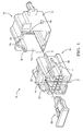
- Fig. 1 illustrates a non-limiting example of a connector system 10 that includes a first connector body 12, hereinafter referred to as the female connector body 12, which defines a shroud 14.
- the female connector body12 is designed to accommodate a number of male or plug electrical terminals (not shown) that are attached to wire cables (not shown), such as those of a wire harness assembly (not shown).
- the female connector body 12 is formed of a dielectric material, such as such as polyamide (PA), polypropylene (PP), or polybutylene terephthalate (PBT).
- PA polyamide
- PP polypropylene
- PBT polybutylene terephthalate
- the connector system 10 also includes a second connector body 16, hereinafter referred to as the male connector body 16, which is configured to be inserted within a cavity 18 defined by the shroud 14 of the female connector body 12 along a first axis, hereinafter referred to as the longitudinal or X axis.
- the male connector body 16 is designed to accommodate a number of female or socket electrical terminals (not shown) that are attached to wire cables (not shown), such as those of another wire harness assembly (not shown).
- the male connector body 16 is also formed of a dielectric material, such as such as PA, PP, or PBT.
- the male connector body 16 defines a first resilient member 20 which is a resilient cantilever beam that is longitudinally oriented.
- the first resilient member 20 is configured to flex along a second axis which is orthogonal to the longitudinal axis, hereinafter referred to as the vertical or Z axis.
- the first resilient member 20, hereafter referred to as the lock arm 20, defines a lock notch 22 that is designed to engage a lock nib 24 that protrudes from the interior of the shroud 14 of the female connector body 12.
- the lock nib 24 is engaged with the lock notch 22
- the male connector body 16 is secured within the shroud 14 of the female connector body 12, thereby limiting relative movement of the male and female connector bodies 12, 16 along the longitudinal axis X.
- a free end 26 of the lock arm 20 may be pressed to disengage the lock nib 24 from the lock notch 22 in order to permit the male connector body 16 to be removed from the shroud 14.
- a portion of the lock arm 20 is proximate a top inner wall 28 of the shroud 14 when the male connector body 16 is fully inserted within the shroud 14 of the female connector body 12.
- the male connector body 16 further includes a second resilient member 30 and a third resilient member 32 which are both resilient cantilever beams.
- the second and third resilient members 30, 32 are also longitudinally oriented.
- the second and third resilient members 30, 32 are configured to flex along a third axis which is orthogonal to the longitudinal X and vertical Z axes, hereinafter referred to as the lateral or Y axis.
- the second and third resilient members 30, 32 flank the lock arm 20 and may be referred to as lock arm protection rails 30, 32.
- the second compliant member 30 is proximate a first inner side wall 34 of the shroud 14 and the third complaint member 32 is proximate a second inner side wall 36 opposite the first inner side wall 34.
- the male connector body 16 further includes a connector position assurance device 38 (CPA) which is slideably retained on the male connector body 16.
- the CPA 38 is also formed of a dielectric material, such as such as PA, PP, or PBT.
- the CPA 38 is slideably moveable between a rearward disengaged position 40 shown in Figs. 2, 3 , and 4 where the lock arm 20 is free to flex bringing the lock notch 22 in and out of engagement with the lock nib 24 and a forward engaged position 42 shown in Figs. 5, 6 and 7 where the CPA 38 prevents the lock arm 20 from flexing and disengaging the lock notch 22 from the lock nib 24.
- the CPA 38 also defines a plurality of wedge members 44, 46, 48.
- the wedge members 44, 46, 48 are located on the rearward portion of the CPA 38 and are configured to contact the resilient members 20, 30, 32 when the CPA 38 is in the engaged position 42 and not contact the resilient members 20, 30, 32 when the CPA 38 is in the disengaged position 40.
- a first wedge member 44 located on a top surface of the CPA 38 is configured contact the free end 26 of the lock arm 20 when the CPA 38 is in the engaged position 42 to urge the lock arm 20 into compressive contact with the top inner wall 28 of the shroud 14 along the vertical axis Z, thereby inhibiting relative motion between the male and female connector bodies 12, 16 along the vertical axis Z.
- a second wedge member 46 located on a side surface of the CPA 38 is configured to urge the second resilient member 30 into compressive contact with the first inner side wall 34 of the shroud 14 along the lateral axis Y and a third wedge member 48 located on an opposite side surface of the CPA 38 is configured to urge the third resilient member 32 into compressive contact with the second inner side wall 36 of the shroud 14 along the lateral axis Y, thereby inhibiting relative motion between the male and female connector bodies 12, 16 along the lateral axis Y.
- compressive contact produces a reaction force between the resilient members 20, 30, 32 and the inner walls 28, 34, 36 of the shroud 14.
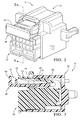
- Figs. 2 - 4 illustrate the connector system 10 with the male connector body 16 fully inserted within the female connector body 12 and the CPA 38 in the rearward disengaged position 40.
- the first wedge member 44 is not in contact with the lock arm 20 nor is the second and third wedge members 46, 48 in contact with the lock arm protection rails 30, 32.
- the lock notch 22 of the lock arm 20 is engaged with the lock nib 24 of the female connector body 12.
- the lock arm 20 is not in contact with the upper inner side wall 28 of the shroud 14.
- the lock protection rails are substantially parallel to each other and are not contacting the first or second inner side walls 34, 36 of the shroud 14.
- substantially parallel means ⁇ 2° of absolutely parallel.
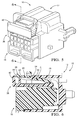
- Figs. 5 - 7 illustrate the connector system 10 with the male connector body 16 fully inserted within the female connector body 12 and the CPA 38 in the forward engaged position 42.
- the first wedge member 44 is in compressive contact with the lock arm 20 and the second and third wedge members 46, 48 are in compressive contact with the lock arm protection rails 30, 32.
- the free end 26 of the lock arm 20 is forced up by the first wedge member 44 contacting the ramp 50 on the bottom side of the lock arm 20.
- the lock arm 20 flexes upward pushing the lock arm 20 into compressive contact with the upper side wall 28 at point A.
- Fig. 5 - 7 illustrate the connector system 10 with the male connector body 16 fully inserted within the female connector body 12 and the CPA 38 in the forward engaged position 42.
- the first wedge member 44 is in compressive contact with the lock arm 20 and the second and third wedge members 46, 48 are in compressive contact with the lock arm protection rails 30, 32.
- the free end 26 of the lock arm 20 is forced up by the first wedge member 44 contacting the ramp
- a connector system 10 having a connector position assurance device 38 that in addition to preventing inadvertent release of the lock arm 20 includes wedge members 44, 46, 48 that force resilient members 20, 30, 32 of the male connector body 16 into compressive contact with the female connector body 12. This provides the benefit of inhibiting relative vertical and/or lateral motion between the connector bodies 12, 16 without the inclusion of sealing elements.
Landscapes
- Details Of Connecting Devices For Male And Female Coupling (AREA)
- Connector Housings Or Holding Contact Members (AREA)
Abstract
Description
- The invention generally relates to a connector system, and more particularly relates to a connector body of the system having a resilient member that is configured to dampen vibration between mating connector bodies in the connector system.
- Sealed connector systems include compliant seals between the mating connector bodies to stop the entry of environmental contaminants, such as, dust, dirt, water or other fluids into the connector bodies of the connector system. These compliant seals also serve to reduce the relative motion between the connector bodies, and hence the electrical terminals within the connector bodies caused by vibration within a vehicle. This relative motion between terminals can cause undesirable intermittent connections or fretting corrosion. Unsealed connection systems do not have compliant seals and typically rely on connector fit/clearances to reduce movement between the connector bodies and can typically can only function in lower vibration environments, such as those associated with a vehicle passenger compartment. Sealed connectors may be used in higher vibration environments where their resistance to environmental contaminants is not required; however, sealed connector systems are typically more expensive than equivalent unsealed connector systems. Therefore, it is desirable to have an unsealed connection system that can withstand higher vibration environments.
- The subject matter discussed in the background section should not be assumed to be prior art merely as a result of its mention in the background section. Similarly, a problem mentioned in the background section or associated with the subject matter of the background section should not be assumed to have been previously recognized in the prior art. The subject matter in the background section merely represents different approaches, which in and of themselves may also be inventions.
- In accordance with one embodiment of this invention, a connector configured to be inserted within a cavity of a shroud defined by a mating connector along a first axis is provided. The connector includes a connector body defining a first resilient member and a first wedge member configured to urge the first resilient member into compressive contact with the shroud of the mating connector along a second axis that is orthogonal to the first axis.
- The connector body may further define second and third resilient members and the connector may further include second and third wedge members that are configured to urge the second and third resilient members into compressive contact with the shroud along a third axis that is orthogonal to both the first axis and the second axis. The first resilient member may be urged into compressive contact with a first inner wall of the shroud, the second resilient member may be urged into compressive contact with a second inner wall of the shroud adjacent the first inner wall, and the third resilient member may be urged into compressive contact with a third inner wall of the shroud opposing the second inner wall. The first, second, and third resilient members may be resilient cantilever beams.
- The first resilient member may define a lock notch that is configured to engage a lock nib defined by the mating connector, thereby securing the connector body within the shroud of the mating connector.
- The connector may also include a connector position assurance device that defines the first, second, and third wedge members. The first, second, and third wedge members are not in contact with the first, second, and third resilient members when the connector position assurance device is in a disengaged position and the first, second, and third wedge members are in compressive contact with the first, second, and third resilient members when the connector position assurance device is in an engaged position. The lock notch may be disengaged from the lock nib by pressing on a free end of the first resilient member when the connector position assurance device is in the disengaged position and wherein the lock notch is inhibited from disengaging the lock nib when the connector position assurance device is in the engaged position.
- In another embodiment of the present invention, a connector system is provided. The connector system includes a first connector body defining a shroud and a second connector body that is configured to be inserted within a cavity defined by the shroud along a first axis. The second connector body includes a first resilient member. The connector system also includes a first wedge member that is configured to urge the first resilient member into compressive contact with the first connector body along a second axis that is orthogonal to the first axis, thereby inhibiting relative motion between the first connector body and the second connector body.
- Further features and advantages of the invention will appear more clearly on a reading of the following detailed description of the preferred embodiment of the invention, which is given by way of non-limiting example only and with reference to the accompanying drawings.
- The present invention will now be described, by way of example with reference to the accompanying drawings, in which:
-
Fig. 1 is an exploded perspective view of a connector system including a connector position assurance device (CPA) having several resilient members and wedge members in accordance with one embodiment; -
Fig. 2 is a perspective view of the connector system ofFig. 1 in an assembled condition with the CPA is a disengaged position in accordance with one embodiment; -
Fig. 3 is a cross sectional side view of the connector system ofFig. 2 in accordance with one embodiment; -
Fig. 4 is a top view of the connector system ofFig. 2 in accordance with one embodiment; -
Fig. 5 is a perspective view of the connector system ofFig. 1 in an assembled condition with the CPA in a engaged position in accordance with one embodiment; -
Fig. 6 is a cross sectional side view of the connector system ofFig. 5 in accordance with one embodiment; and -
Fig. 7 is top view of the connector system ofFig. 5 in accordance with one embodiment. - An unsealed connector system having features to reduce or inhibit relative motion between the connector bodies of the connection system is presented herein. One of the connector bodies has at least one resilient member that is wedged against a shroud of the mating connector body, thus limiting the relative motion between the connector bodies along at least one axis. One embodiment described here includes three resilient members and a connector position assurance device that has three wedge members which force the resilient members against the interior walls of the shroud, thus limiting the relative motion between the connector bodies along at least two orthogonal axes.
-
Fig. 1 illustrates a non-limiting example of aconnector system 10 that includes afirst connector body 12, hereinafter referred to as thefemale connector body 12, which defines ashroud 14. The female connector body12 is designed to accommodate a number of male or plug electrical terminals (not shown) that are attached to wire cables (not shown), such as those of a wire harness assembly (not shown). Thefemale connector body 12 is formed of a dielectric material, such as such as polyamide (PA), polypropylene (PP), or polybutylene terephthalate (PBT). - The
connector system 10 also includes asecond connector body 16, hereinafter referred to as themale connector body 16, which is configured to be inserted within acavity 18 defined by theshroud 14 of thefemale connector body 12 along a first axis, hereinafter referred to as the longitudinal or X axis. Themale connector body 16 is designed to accommodate a number of female or socket electrical terminals (not shown) that are attached to wire cables (not shown), such as those of another wire harness assembly (not shown). Themale connector body 16 is also formed of a dielectric material, such as such as PA, PP, or PBT. - The
male connector body 16 defines a firstresilient member 20 which is a resilient cantilever beam that is longitudinally oriented. The firstresilient member 20 is configured to flex along a second axis which is orthogonal to the longitudinal axis, hereinafter referred to as the vertical or Z axis. The firstresilient member 20, hereafter referred to as thelock arm 20, defines alock notch 22 that is designed to engage alock nib 24 that protrudes from the interior of theshroud 14 of thefemale connector body 12. When thelock nib 24 is engaged with thelock notch 22, themale connector body 16 is secured within theshroud 14 of thefemale connector body 12, thereby limiting relative movement of the male andfemale connector bodies free end 26 of thelock arm 20 may be pressed to disengage thelock nib 24 from thelock notch 22 in order to permit themale connector body 16 to be removed from theshroud 14. A portion of thelock arm 20 is proximate a topinner wall 28 of theshroud 14 when themale connector body 16 is fully inserted within theshroud 14 of thefemale connector body 12. - The
male connector body 16 further includes a secondresilient member 30 and a thirdresilient member 32 which are both resilient cantilever beams. The second and thirdresilient members resilient members resilient members lock arm 20 and may be referred to as lockarm protection rails compliant member 30 is proximate a firstinner side wall 34 of theshroud 14 and thethird complaint member 32 is proximate a secondinner side wall 36 opposite the firstinner side wall 34. - The
male connector body 16 further includes a connector position assurance device 38 (CPA) which is slideably retained on themale connector body 16. TheCPA 38 is also formed of a dielectric material, such as such as PA, PP, or PBT. TheCPA 38 is slideably moveable between a rearwarddisengaged position 40 shown inFigs. 2, 3 , and4 where thelock arm 20 is free to flex bringing thelock notch 22 in and out of engagement with thelock nib 24 and a forward engagedposition 42 shown inFigs. 5, 6 and7 where theCPA 38 prevents thelock arm 20 from flexing and disengaging thelock notch 22 from thelock nib 24. - The
CPA 38 also defines a plurality ofwedge members wedge members CPA 38 and are configured to contact theresilient members CPA 38 is in the engagedposition 42 and not contact theresilient members CPA 38 is in thedisengaged position 40. Afirst wedge member 44 located on a top surface of theCPA 38 is configured contact thefree end 26 of thelock arm 20 when theCPA 38 is in the engagedposition 42 to urge thelock arm 20 into compressive contact with the topinner wall 28 of theshroud 14 along the vertical axis Z, thereby inhibiting relative motion between the male andfemale connector bodies second wedge member 46 located on a side surface of theCPA 38 is configured to urge the secondresilient member 30 into compressive contact with the firstinner side wall 34 of theshroud 14 along the lateral axis Y and athird wedge member 48 located on an opposite side surface of theCPA 38 is configured to urge the thirdresilient member 32 into compressive contact with the secondinner side wall 36 of theshroud 14 along the lateral axis Y, thereby inhibiting relative motion between the male andfemale connector bodies resilient members inner walls shroud 14. -
Figs. 2 - 4 illustrate theconnector system 10 with themale connector body 16 fully inserted within thefemale connector body 12 and theCPA 38 in the rearwarddisengaged position 40. In thisdisengaged position 40, thefirst wedge member 44 is not in contact with thelock arm 20 nor is the second andthird wedge members Fig. 3 , thelock notch 22 of thelock arm 20 is engaged with thelock nib 24 of thefemale connector body 12. However, thelock arm 20 is not in contact with the upperinner side wall 28 of theshroud 14. As shown inFig. 4 , the lock protection rails are substantially parallel to each other and are not contacting the first or secondinner side walls shroud 14. As used herein, substantially parallel means ± 2° of absolutely parallel. -
Figs. 5 - 7 illustrate theconnector system 10 with themale connector body 16 fully inserted within thefemale connector body 12 and theCPA 38 in the forward engagedposition 42. In this engagedposition 42, thefirst wedge member 44 is in compressive contact with thelock arm 20 and the second andthird wedge members Fig. 6 , thefree end 26 of thelock arm 20 is forced up by thefirst wedge member 44 contacting theramp 50 on the bottom side of thelock arm 20. Thelock arm 20 flexes upward pushing thelock arm 20 into compressive contact with theupper side wall 28 at point A. As shown inFig. 7 , the free ends 52, 54 of the lock arm protection rails 30, 32 are forced apart by the second andthird wedge members side walls shroud 14 at points B and C. - The examples presented herein are directed to electrical connectors, however other embodiments of the
connector system 10 may be envisioned that are adapted for use with hydraulic, pneumatic, optical, or hybrid connectors including connections of various types. Although the embodiment presented here is an unsealed connector system, other embodiments of the connector system may be envisioned that also include environmental seals. - Accordingly, a
connector system 10 having a connectorposition assurance device 38 that in addition to preventing inadvertent release of thelock arm 20 includeswedge members resilient members male connector body 16 into compressive contact with thefemale connector body 12. This provides the benefit of inhibiting relative vertical and/or lateral motion between theconnector bodies - While this invention has been described in terms of the preferred embodiments thereof, it is not intended to be so limited, but rather only to the extent set forth in the claims that follow. Moreover, the use of the terms first, second, etc. does not denote any order of importance, but rather the terms first, second, etc. are used to distinguish one element from another. Furthermore, the use of the terms a, an, etc. do not denote a limitation of quantity, but rather denote the presence of at least one of the referenced items.
Claims (15)
- Connector configured to be inserted within a cavity (18) of a shroud (14) defined by a mating connector along a first axis (X), comprising:a connector body (16) defining a first resilient member (20); anda first wedge member (44) configured to urge the first resilient member (20) into compressive contact with the shroud (14) of the mating connector along a second axis (Z) orthogonal to the first axis (X).
- Connector in accordance with claim 1, wherein the connector body (16) further defines a second resilient member (30) and wherein said connector further includes a second wedge member (46) configured to urge the second resilient member (30) into compressive contact with the shroud (14) along a third axis (Y) orthogonal to the first axis (X) and the second axis (Z).
- Connector in accordance with claim 2, wherein the connector body (16) further defines a third resilient member (32) and wherein said connector further includes a third wedge member (48) configured to urge the third resilient member (32) into compressive contact with the shroud (14) along the third axis (Y).
- Connector in accordance with claim 3, wherein the first resilient member (20) is urged into compressive contact with a first inner wall (30) of the shroud (14), the second resilient member (30) is urged into compressive contact with a second inner wall (34) of the shroud (14) adjacent the first inner wall (30), and the third resilient member (32) is urged into compressive contact with a third inner wall (36) of the shroud (14) opposing the second inner wall (34).
- Connector in accordance with one of the preceding claims, wherein the first resilient member (20) is a resilient cantilever beam.
- Connector in accordance with one of the preceding claims, wherein the second resilient member (30) and the third resilient member (32) are resilient cantilever beams.
- Connector in accordance with one of the preceding claims, the first resilient member (20) defines a lock notch (22) configured to engage a lock nib (24) defined by the mating connector, thereby securing the connector body (16) within the shroud (14) of the mating connector.
- Connector in accordance with one of the preceding claims, further comprising a connector position assurance device (38) that defines the first, second, and third wedge members (44, 46, 48).
- Connector in accordance with one of the claims 3-8, wherein the first, second, and third wedge members (44, 46, 48) are not in contact with the first, second, and third resilient members (20, 30, 32) when the connector position assurance device (38) is in a disengaged position (40) and the first, second, and third wedge members (44, 46, 48) are in compressive contact with the first, second, and third resilient members (20, 30, 32) when the connector position assurance device (38) is in an engaged position (42).
- Connector in accordance with one of the claims 7-9, wherein the lock notch (22) may be disengaged from the lock nib (24) by pressing on a free end (26) of the first resilient member (20) when the connector position assurance device (38) is in the disengaged position (40) and wherein the lock notch (22) is inhibited from disengaging the lock nib (24) when the connector position assurance device (38) is in the engaged position (42).
- Connector system (10), comprising:a first connector body (12) defining a shroud (14);a connector according to one of the preceding claims, the connector body being a second connector body (16) configured to be inserted within a cavity (18) defined by said shroud (14) along a first axis (X), wherein the first wedge member (44) is configured to urge the first resilient member (20) into compressive contact with the first connector body (12) along a second axis (Z) orthogonal to the first axis (X), thereby inhibiting relative motion between the first connector body (12) and the second connector body (16).
- Connector system (10) in accordance with claim 11, wherein the second connector body (16) further defines a second resilient member (30) and wherein said connector system (10) further includes a second wedge member (46) configured to urge the second resilient member (30) into compressive contact with the first connector body (12) along a third axis (Y) orthogonal to the first axis (X) and the second axis (Z) and/or wherein the second connector body (16) further defines a third resilient member (32) and wherein said connector system (10) further includes a third wedge member (48) configured to urge the third resilient member (32) into compressive contact with the first connector body (12) along the third axis (Y) and/or wherein the first resilient member (20) is urged into compressive contact with a first inner wall (30) of the shroud (14), the second resilient member (30) is urged into compressive contact with a second inner wall (34) of the shroud (14) adjacent the first inner wall (30), and the third resilient member (32) is urged into compressive contact with a third inner wall (36) of the shroud (14) opposing the second inner wall (34).
- Connector system (10) in accordance with claim 12, wherein the first connector body (12) defines an inwardly extending lock nib (24) and the first resilient member (20) defines a lock notch (22) configured to engage said lock nib (24), thereby securing the second connector body (16) within the shroud (14) of the first connector body (12).
- Connector system (10) in accordance with one of the claims 12-13, further comprising a connector position assurance device (38) that defines the first, second, and third wedge members (44) and wherein the first, second, and third wedge members (44) are not in contact with the first, second, and third resilient members (20) when the connector position assurance device (38) is in a disengaged position (40) and the first, second, and third wedge members (44) are in compressive contact with the first, second, and third resilient members (20) when the connector position assurance device (38) is in an engaged position (42).
- Connector system (10) in accordance with claim 14, wherein the lock notch (22) may be disengaged from the lock nib (24) by pressing on a free end (26) of the first resilient member (20) when the connector position assurance device (38) is in the disengaged position (40) and wherein the lock notch (22) is inhibited from disengaging the lock nib (24) when the connector position assurance device (38) is in the engaged position (42).
Applications Claiming Priority (1)
| Application Number | Priority Date | Filing Date | Title |
|---|---|---|---|
| US14/250,658 US9281619B2 (en) | 2014-04-11 | 2014-04-11 | Vibration resistant connector system with connector position assurance device |
Publications (2)
| Publication Number | Publication Date |
|---|---|
| EP2937947A1 true EP2937947A1 (en) | 2015-10-28 |
| EP2937947B1 EP2937947B1 (en) | 2017-06-14 |
Family
ID=53015511
Family Applications (1)
| Application Number | Title | Priority Date | Filing Date |
|---|---|---|---|
| EP15162762.7A Active EP2937947B1 (en) | 2014-04-11 | 2015-04-08 | Vibration resistant connector system with connector position assurance device |
Country Status (3)
| Country | Link |
|---|---|
| US (1) | US9281619B2 (en) |
| EP (1) | EP2937947B1 (en) |
| CN (1) | CN104979708B (en) |
Families Citing this family (36)
| Publication number | Priority date | Publication date | Assignee | Title |
|---|---|---|---|---|
| DE202014006815U1 (en) * | 2014-08-21 | 2014-09-09 | Rosenberger Hochfrequenztechnik Gmbh & Co. Kg | High current plug with clip closure |
| DE102015201089A1 (en) * | 2015-01-22 | 2016-07-28 | Te Connectivity Germany Gmbh | Intermediate housing with a CPA receptacle and connector systems comprising such |
| KR101835115B1 (en) * | 2015-09-16 | 2018-04-19 | 몰렉스 엘엘씨 | Connector assembly having cpa |
| JP6244345B2 (en) * | 2015-10-28 | 2017-12-06 | 矢崎総業株式会社 | connector |
| US9893467B2 (en) * | 2015-12-11 | 2018-02-13 | J.S.T. Corporation | Connector position assurance device, a connector apparatus having male and female connector assemblies with terminal position assurance devices and the connector position assurance device, a male connector assembly, a female connector assembly, and a method for assembling the connector apparatus |
| US10044140B1 (en) * | 2015-12-28 | 2018-08-07 | Amazon Technologies, Inc. | Physical cable seating confirmation for network cables |
| JP6213592B2 (en) * | 2016-02-25 | 2017-10-18 | 第一精工株式会社 | connector |
| JP6213591B2 (en) * | 2016-02-25 | 2017-10-18 | 第一精工株式会社 | connector |
| JP6288125B2 (en) * | 2016-03-03 | 2018-03-07 | 第一精工株式会社 | connector |
| FR3049118A1 (en) * | 2016-03-15 | 2017-09-22 | Tyco Electronics France Sas | CONNECTOR POSITION ASSURANCE DEVICE, CONNECTOR HOUSING, AND ELECTRICAL CONNECTOR SYSTEM |
| US9680256B1 (en) * | 2016-03-17 | 2017-06-13 | Te Connectivity Corporation | Connector system with connector position assurance |
| US10038278B2 (en) | 2016-03-17 | 2018-07-31 | Te Connectivity Corporation | Electrical connector having a connector position assurance element |
| US9935389B1 (en) * | 2017-02-23 | 2018-04-03 | Sumitomo Wiring Systems, Ltd. | Inline connector housing assemblies with removable TPA |
| US10199753B2 (en) * | 2017-04-28 | 2019-02-05 | Corning Optical Communications Rf Llc | Multi-pin connector block assembly |
| US10855025B2 (en) * | 2017-05-01 | 2020-12-01 | J.S.T. Corporation | Connector position assurance device, connector system and method for operating the connector system |
| JP6981844B2 (en) * | 2017-10-23 | 2021-12-17 | タイコエレクトロニクスジャパン合同会社 | Connector and connector assembly |
| US11133622B2 (en) * | 2017-12-26 | 2021-09-28 | Sumitomo Wiring Systems, Ltd. | Connector with connection detection member |
| CN108173083A (en) * | 2018-01-21 | 2018-06-15 | 顺科新能源技术股份有限公司 | A high-voltage energy storage quick-plug connector |
| US10587076B2 (en) * | 2018-03-23 | 2020-03-10 | Te Connectivity Corporation | Connector position assurance member |
| US10468805B2 (en) * | 2018-03-23 | 2019-11-05 | Te Connectivity Corporation | Connector position assurance member |
| US10404012B1 (en) * | 2018-04-20 | 2019-09-03 | Te Connectivity Corporation | Electrical connector with connector position assurance element |
| US10826234B2 (en) * | 2018-04-23 | 2020-11-03 | Aptiv Technologies Limited | Connector assembly with direct mount housing |
| US10340632B1 (en) * | 2018-06-06 | 2019-07-02 | Lear Corporation | Electrical connector assembly with staged release |
| KR102234247B1 (en) * | 2018-08-29 | 2021-04-02 | 앱티브 테크놀러지스 리미티드 | Connector and connector assembly comprising the same |
| JP6839145B2 (en) * | 2018-09-03 | 2021-03-03 | 矢崎総業株式会社 | connector |
| JP6996487B2 (en) * | 2018-12-25 | 2022-01-17 | 株式会社オートネットワーク技術研究所 | connector |
| JP6871228B2 (en) * | 2018-12-27 | 2021-05-12 | 矢崎総業株式会社 | connector |
| CN117154466A (en) * | 2020-03-05 | 2023-12-01 | 上海莫仕连接器有限公司 | Second connector |
| US11594838B2 (en) * | 2020-04-28 | 2023-02-28 | Foxconn (Kunshan) Computer Connector Co., Ltd. | Connector assembly with connector position assurance |
| KR102817543B1 (en) * | 2020-10-30 | 2025-06-05 | 현대자동차주식회사 | Joint connector |
| US11837806B2 (en) * | 2020-12-09 | 2023-12-05 | Lear Corporation | Grounding electrical connector |
| CN112615210A (en) * | 2020-12-23 | 2021-04-06 | 上海昆文连接器系统有限公司 | Automobile connector fixing and locking structure and using method |
| CN113571962B (en) * | 2021-04-30 | 2023-09-01 | 安波福连接器系统(南通)有限公司 | Connector and connector assembly |
| CN114709668A (en) | 2021-12-17 | 2022-07-05 | 安波福连接器系统(南通)有限公司 | Connector position holding device and connector assembly |
| US20230318220A1 (en) * | 2022-04-05 | 2023-10-05 | Aptiv Technologies Limited | Ergonomic pushing surface for electrical components |
| JP2024072416A (en) * | 2022-11-16 | 2024-05-28 | 日本航空電子工業株式会社 | Connector and connector assembly |
Citations (3)
| Publication number | Priority date | Publication date | Assignee | Title |
|---|---|---|---|---|
| US6435895B1 (en) * | 2001-04-27 | 2002-08-20 | Delphi Technologies, Inc. | Connector position assurance device |
| US6824417B1 (en) * | 2002-07-24 | 2004-11-30 | Sumitomo Wiring Systems, Ltd. | Connection detecting connector and a connection detecting connector assembly |
| EP2637260A1 (en) * | 2012-03-09 | 2013-09-11 | Sumitomo Wiring Systems, Ltd. | Connector, connector assembly and assembling method therefor |
Family Cites Families (17)
| Publication number | Priority date | Publication date | Assignee | Title |
|---|---|---|---|---|
| US5192225A (en) * | 1990-11-08 | 1993-03-09 | Yazaki Corporation | Connector locking connection detection device |
| US5257944A (en) * | 1992-07-14 | 1993-11-02 | Interlock Corporation | Connector position assurance assembly |
| US5507666A (en) * | 1993-12-28 | 1996-04-16 | Yazaki Corporation | Lock securing mechanism for connectors |
| JP2910609B2 (en) * | 1995-02-24 | 1999-06-23 | 住友電装株式会社 | Connector housing locking mechanism |
| JP3685290B2 (en) * | 1997-07-01 | 2005-08-17 | 住友電装株式会社 | connector |
| JP3467202B2 (en) * | 1998-04-17 | 2003-11-17 | 矢崎総業株式会社 | Connector locking mechanism |
| US6290539B1 (en) * | 1999-04-30 | 2001-09-18 | Cardell Corporation | Electrical connector having a two-piece socket portion |
| JP3976134B2 (en) * | 2001-09-05 | 2007-09-12 | 矢崎総業株式会社 | Half-mating prevention connector |
| US6884106B2 (en) * | 2002-02-07 | 2005-04-26 | Tyco Electronics Corporation | Electrical connector assembly |
| US6780045B2 (en) * | 2002-03-06 | 2004-08-24 | Tyco Electronics Corporation | Connector position assurance device |
| US6857892B2 (en) | 2003-06-05 | 2005-02-22 | Fci Americas Technology, Inc. | Electrical connector with connector position assurance member |
| US7399195B2 (en) * | 2006-12-06 | 2008-07-15 | J.S.T. Corporation | Connector position assurance device and connector assembly incorporating the same |
| SG149732A1 (en) * | 2007-07-31 | 2009-02-27 | Mea Technologies Pte Ltd | Electric connector |
| DE102008035193A1 (en) * | 2008-07-28 | 2010-02-11 | Tyco Electronics Amp Gmbh | Controllable plug connection and method for checking the plug state of a plug connection |
| US7682181B1 (en) * | 2008-09-09 | 2010-03-23 | Tyco Electronics Corporation | Latch securing member |
| US8092245B2 (en) * | 2008-10-14 | 2012-01-10 | Delphi Technologies, Inc. | Electrical connector assembly |
| JP5751196B2 (en) * | 2012-03-09 | 2015-07-22 | 住友電装株式会社 | connector |
-
2014
- 2014-04-11 US US14/250,658 patent/US9281619B2/en active Active
-
2015
- 2015-03-12 CN CN201510107988.6A patent/CN104979708B/en active Active
- 2015-04-08 EP EP15162762.7A patent/EP2937947B1/en active Active
Patent Citations (3)
| Publication number | Priority date | Publication date | Assignee | Title |
|---|---|---|---|---|
| US6435895B1 (en) * | 2001-04-27 | 2002-08-20 | Delphi Technologies, Inc. | Connector position assurance device |
| US6824417B1 (en) * | 2002-07-24 | 2004-11-30 | Sumitomo Wiring Systems, Ltd. | Connection detecting connector and a connection detecting connector assembly |
| EP2637260A1 (en) * | 2012-03-09 | 2013-09-11 | Sumitomo Wiring Systems, Ltd. | Connector, connector assembly and assembling method therefor |
Also Published As
| Publication number | Publication date |
|---|---|
| EP2937947B1 (en) | 2017-06-14 |
| US9281619B2 (en) | 2016-03-08 |
| US20150295354A1 (en) | 2015-10-15 |
| CN104979708A (en) | 2015-10-14 |
| CN104979708B (en) | 2017-08-29 |
Similar Documents
| Publication | Publication Date | Title |
|---|---|---|
| EP2937947B1 (en) | Vibration resistant connector system with connector position assurance device | |
| US9350116B1 (en) | Connector system with connector position assurance device | |
| US9300085B2 (en) | Electrical wiring assembly and vibration resistant electrical connector for same | |
| JP5704021B2 (en) | Rubber stopper and waterproof connector | |
| US8376778B2 (en) | Connector with resilient retainer for contact | |
| US9270055B2 (en) | Connector with vibratory connection feedback | |
| EP2930795A1 (en) | Sealed connector with an extended seal sleeve and an anti-water pooling retainer | |
| US10236629B2 (en) | Electrical connector with retractable terminal-stabilizer | |
| EP3477787B1 (en) | Electrical connector with position assurance device | |
| EP2975698A1 (en) | Electrical connector with a terminal position assurance device | |
| JP6138428B2 (en) | connector | |
| CN104143726B (en) | Connector | |
| US9099809B2 (en) | Connection system including connector body with integral primary and secondary lock | |
| JP2017204399A (en) | connector | |
| CN109196729B (en) | Connector with a locking member | |
| JP5912966B2 (en) | connector | |
| KR20170070997A (en) | Locking structure of connector and connector | |
| CN104659521A (en) | Wire holder | |
| US9537256B2 (en) | Connector | |
| CN112152015B (en) | Connector | |
| US10505314B1 (en) | Electrical connector with a connector position assurance member for a shrouded latch | |
| US12562520B2 (en) | Connector assembly with terminal position assurance and blocking feature | |
| WO2013153089A1 (en) | Electrical contact device, in particular electrical socket contact device | |
| US9407040B2 (en) | Connector with functional portion projecting from side surface of connector hosing and terminal accommodating chamber in the functional portion | |
| JP7575437B2 (en) | connector |
Legal Events
| Date | Code | Title | Description |
|---|---|---|---|
| PUAI | Public reference made under article 153(3) epc to a published international application that has entered the european phase |
Free format text: ORIGINAL CODE: 0009012 |
|
| AK | Designated contracting states |
Kind code of ref document: A1 Designated state(s): AL AT BE BG CH CY CZ DE DK EE ES FI FR GB GR HR HU IE IS IT LI LT LU LV MC MK MT NL NO PL PT RO RS SE SI SK SM TR |
|
| AX | Request for extension of the european patent |
Extension state: BA ME |
|
| 17P | Request for examination filed |
Effective date: 20160428 |
|
| RBV | Designated contracting states (corrected) |
Designated state(s): AL AT BE BG CH CY CZ DE DK EE ES FI FR GB GR HR HU IE IS IT LI LT LU LV MC MK MT NL NO PL PT RO RS SE SI SK SM TR |
|
| 17Q | First examination report despatched |
Effective date: 20161017 |
|
| GRAP | Despatch of communication of intention to grant a patent |
Free format text: ORIGINAL CODE: EPIDOSNIGR1 |
|
| RIC1 | Information provided on ipc code assigned before grant |
Ipc: H01R 13/627 20060101AFI20161202BHEP Ipc: H01R 13/639 20060101ALI20161202BHEP |
|
| INTG | Intention to grant announced |
Effective date: 20170103 |
|
| GRAS | Grant fee paid |
Free format text: ORIGINAL CODE: EPIDOSNIGR3 |
|
| GRAA | (expected) grant |
Free format text: ORIGINAL CODE: 0009210 |
|
| AK | Designated contracting states |
Kind code of ref document: B1 Designated state(s): AL AT BE BG CH CY CZ DE DK EE ES FI FR GB GR HR HU IE IS IT LI LT LU LV MC MK MT NL NO PL PT RO RS SE SI SK SM TR |
|
| REG | Reference to a national code |
Ref country code: GB Ref legal event code: FG4D |
|
| REG | Reference to a national code |
Ref country code: CH Ref legal event code: EP Ref country code: AT Ref legal event code: REF Ref document number: 901783 Country of ref document: AT Kind code of ref document: T Effective date: 20170615 |
|
| REG | Reference to a national code |
Ref country code: IE Ref legal event code: FG4D |
|
| REG | Reference to a national code |
Ref country code: DE Ref legal event code: R096 Ref document number: 602015003060 Country of ref document: DE |
|
| REG | Reference to a national code |
Ref country code: NL Ref legal event code: MP Effective date: 20170614 |
|
| REG | Reference to a national code |
Ref country code: LT Ref legal event code: MG4D |
|
| PG25 | Lapsed in a contracting state [announced via postgrant information from national office to epo] |
Ref country code: LT Free format text: LAPSE BECAUSE OF FAILURE TO SUBMIT A TRANSLATION OF THE DESCRIPTION OR TO PAY THE FEE WITHIN THE PRESCRIBED TIME-LIMIT Effective date: 20170614 Ref country code: HR Free format text: LAPSE BECAUSE OF FAILURE TO SUBMIT A TRANSLATION OF THE DESCRIPTION OR TO PAY THE FEE WITHIN THE PRESCRIBED TIME-LIMIT Effective date: 20170614 Ref country code: NO Free format text: LAPSE BECAUSE OF FAILURE TO SUBMIT A TRANSLATION OF THE DESCRIPTION OR TO PAY THE FEE WITHIN THE PRESCRIBED TIME-LIMIT Effective date: 20170914 Ref country code: GR Free format text: LAPSE BECAUSE OF FAILURE TO SUBMIT A TRANSLATION OF THE DESCRIPTION OR TO PAY THE FEE WITHIN THE PRESCRIBED TIME-LIMIT Effective date: 20170915 Ref country code: FI Free format text: LAPSE BECAUSE OF FAILURE TO SUBMIT A TRANSLATION OF THE DESCRIPTION OR TO PAY THE FEE WITHIN THE PRESCRIBED TIME-LIMIT Effective date: 20170614 |
|
| REG | Reference to a national code |
Ref country code: AT Ref legal event code: MK05 Ref document number: 901783 Country of ref document: AT Kind code of ref document: T Effective date: 20170614 |
|
| PG25 | Lapsed in a contracting state [announced via postgrant information from national office to epo] |
Ref country code: NL Free format text: LAPSE BECAUSE OF FAILURE TO SUBMIT A TRANSLATION OF THE DESCRIPTION OR TO PAY THE FEE WITHIN THE PRESCRIBED TIME-LIMIT Effective date: 20170614 Ref country code: RS Free format text: LAPSE BECAUSE OF FAILURE TO SUBMIT A TRANSLATION OF THE DESCRIPTION OR TO PAY THE FEE WITHIN THE PRESCRIBED TIME-LIMIT Effective date: 20170614 Ref country code: SE Free format text: LAPSE BECAUSE OF FAILURE TO SUBMIT A TRANSLATION OF THE DESCRIPTION OR TO PAY THE FEE WITHIN THE PRESCRIBED TIME-LIMIT Effective date: 20170614 Ref country code: BG Free format text: LAPSE BECAUSE OF FAILURE TO SUBMIT A TRANSLATION OF THE DESCRIPTION OR TO PAY THE FEE WITHIN THE PRESCRIBED TIME-LIMIT Effective date: 20170914 Ref country code: LV Free format text: LAPSE BECAUSE OF FAILURE TO SUBMIT A TRANSLATION OF THE DESCRIPTION OR TO PAY THE FEE WITHIN THE PRESCRIBED TIME-LIMIT Effective date: 20170614 |
|
| PG25 | Lapsed in a contracting state [announced via postgrant information from national office to epo] |
Ref country code: EE Free format text: LAPSE BECAUSE OF FAILURE TO SUBMIT A TRANSLATION OF THE DESCRIPTION OR TO PAY THE FEE WITHIN THE PRESCRIBED TIME-LIMIT Effective date: 20170614 Ref country code: SK Free format text: LAPSE BECAUSE OF FAILURE TO SUBMIT A TRANSLATION OF THE DESCRIPTION OR TO PAY THE FEE WITHIN THE PRESCRIBED TIME-LIMIT Effective date: 20170614 Ref country code: AT Free format text: LAPSE BECAUSE OF FAILURE TO SUBMIT A TRANSLATION OF THE DESCRIPTION OR TO PAY THE FEE WITHIN THE PRESCRIBED TIME-LIMIT Effective date: 20170614 Ref country code: RO Free format text: LAPSE BECAUSE OF FAILURE TO SUBMIT A TRANSLATION OF THE DESCRIPTION OR TO PAY THE FEE WITHIN THE PRESCRIBED TIME-LIMIT Effective date: 20170614 Ref country code: CZ Free format text: LAPSE BECAUSE OF FAILURE TO SUBMIT A TRANSLATION OF THE DESCRIPTION OR TO PAY THE FEE WITHIN THE PRESCRIBED TIME-LIMIT Effective date: 20170614 |
|
| PG25 | Lapsed in a contracting state [announced via postgrant information from national office to epo] |
Ref country code: SM Free format text: LAPSE BECAUSE OF FAILURE TO SUBMIT A TRANSLATION OF THE DESCRIPTION OR TO PAY THE FEE WITHIN THE PRESCRIBED TIME-LIMIT Effective date: 20170614 Ref country code: PL Free format text: LAPSE BECAUSE OF FAILURE TO SUBMIT A TRANSLATION OF THE DESCRIPTION OR TO PAY THE FEE WITHIN THE PRESCRIBED TIME-LIMIT Effective date: 20170614 Ref country code: IS Free format text: LAPSE BECAUSE OF FAILURE TO SUBMIT A TRANSLATION OF THE DESCRIPTION OR TO PAY THE FEE WITHIN THE PRESCRIBED TIME-LIMIT Effective date: 20171014 Ref country code: IT Free format text: LAPSE BECAUSE OF FAILURE TO SUBMIT A TRANSLATION OF THE DESCRIPTION OR TO PAY THE FEE WITHIN THE PRESCRIBED TIME-LIMIT Effective date: 20170614 Ref country code: ES Free format text: LAPSE BECAUSE OF FAILURE TO SUBMIT A TRANSLATION OF THE DESCRIPTION OR TO PAY THE FEE WITHIN THE PRESCRIBED TIME-LIMIT Effective date: 20170614 |
|
| REG | Reference to a national code |
Ref country code: DE Ref legal event code: R097 Ref document number: 602015003060 Country of ref document: DE |
|
| PLBE | No opposition filed within time limit |
Free format text: ORIGINAL CODE: 0009261 |
|
| STAA | Information on the status of an ep patent application or granted ep patent |
Free format text: STATUS: NO OPPOSITION FILED WITHIN TIME LIMIT |
|
| REG | Reference to a national code |
Ref country code: FR Ref legal event code: PLFP Year of fee payment: 4 |
|
| PG25 | Lapsed in a contracting state [announced via postgrant information from national office to epo] |
Ref country code: DK Free format text: LAPSE BECAUSE OF FAILURE TO SUBMIT A TRANSLATION OF THE DESCRIPTION OR TO PAY THE FEE WITHIN THE PRESCRIBED TIME-LIMIT Effective date: 20170614 |
|
| 26N | No opposition filed |
Effective date: 20180315 |
|
| PG25 | Lapsed in a contracting state [announced via postgrant information from national office to epo] |
Ref country code: SI Free format text: LAPSE BECAUSE OF FAILURE TO SUBMIT A TRANSLATION OF THE DESCRIPTION OR TO PAY THE FEE WITHIN THE PRESCRIBED TIME-LIMIT Effective date: 20170614 |
|
| PG25 | Lapsed in a contracting state [announced via postgrant information from national office to epo] |
Ref country code: MC Free format text: LAPSE BECAUSE OF FAILURE TO SUBMIT A TRANSLATION OF THE DESCRIPTION OR TO PAY THE FEE WITHIN THE PRESCRIBED TIME-LIMIT Effective date: 20170614 |
|
| REG | Reference to a national code |
Ref country code: CH Ref legal event code: PL |
|
| REG | Reference to a national code |
Ref country code: DE Ref legal event code: R081 Ref document number: 602015003060 Country of ref document: DE Owner name: APTIV TECHNOLOGIES LIMITED, BB Free format text: FORMER OWNER: DELPHI TECHNOLOGIES, INC., TROY, MICH., US |
|
| REG | Reference to a national code |
Ref country code: BE Ref legal event code: MM Effective date: 20180430 |
|
| REG | Reference to a national code |
Ref country code: IE Ref legal event code: MM4A |
|
| PG25 | Lapsed in a contracting state [announced via postgrant information from national office to epo] |
Ref country code: LU Free format text: LAPSE BECAUSE OF NON-PAYMENT OF DUE FEES Effective date: 20180408 |
|
| REG | Reference to a national code |
Ref country code: GB Ref legal event code: 732E Free format text: REGISTERED BETWEEN 20190117 AND 20190123 |
|
| REG | Reference to a national code |
Ref country code: GB Ref legal event code: 732E Free format text: REGISTERED BETWEEN 20190124 AND 20190130 |
|
| PG25 | Lapsed in a contracting state [announced via postgrant information from national office to epo] |
Ref country code: LI Free format text: LAPSE BECAUSE OF NON-PAYMENT OF DUE FEES Effective date: 20180430 Ref country code: BE Free format text: LAPSE BECAUSE OF NON-PAYMENT OF DUE FEES Effective date: 20180430 Ref country code: CH Free format text: LAPSE BECAUSE OF NON-PAYMENT OF DUE FEES Effective date: 20180430 |
|
| PG25 | Lapsed in a contracting state [announced via postgrant information from national office to epo] |
Ref country code: IE Free format text: LAPSE BECAUSE OF NON-PAYMENT OF DUE FEES Effective date: 20180408 |
|
| PG25 | Lapsed in a contracting state [announced via postgrant information from national office to epo] |
Ref country code: MT Free format text: LAPSE BECAUSE OF NON-PAYMENT OF DUE FEES Effective date: 20180408 |
|
| PG25 | Lapsed in a contracting state [announced via postgrant information from national office to epo] |
Ref country code: TR Free format text: LAPSE BECAUSE OF FAILURE TO SUBMIT A TRANSLATION OF THE DESCRIPTION OR TO PAY THE FEE WITHIN THE PRESCRIBED TIME-LIMIT Effective date: 20170614 |
|
| PG25 | Lapsed in a contracting state [announced via postgrant information from national office to epo] |
Ref country code: PT Free format text: LAPSE BECAUSE OF FAILURE TO SUBMIT A TRANSLATION OF THE DESCRIPTION OR TO PAY THE FEE WITHIN THE PRESCRIBED TIME-LIMIT Effective date: 20170614 |
|
| PG25 | Lapsed in a contracting state [announced via postgrant information from national office to epo] |
Ref country code: CY Free format text: LAPSE BECAUSE OF FAILURE TO SUBMIT A TRANSLATION OF THE DESCRIPTION OR TO PAY THE FEE WITHIN THE PRESCRIBED TIME-LIMIT Effective date: 20170614 Ref country code: MK Free format text: LAPSE BECAUSE OF NON-PAYMENT OF DUE FEES Effective date: 20170614 Ref country code: HU Free format text: LAPSE BECAUSE OF FAILURE TO SUBMIT A TRANSLATION OF THE DESCRIPTION OR TO PAY THE FEE WITHIN THE PRESCRIBED TIME-LIMIT; INVALID AB INITIO Effective date: 20150408 |
|
| PG25 | Lapsed in a contracting state [announced via postgrant information from national office to epo] |
Ref country code: AL Free format text: LAPSE BECAUSE OF FAILURE TO SUBMIT A TRANSLATION OF THE DESCRIPTION OR TO PAY THE FEE WITHIN THE PRESCRIBED TIME-LIMIT Effective date: 20170614 |
|
| P01 | Opt-out of the competence of the unified patent court (upc) registered |
Effective date: 20230425 |
|
| REG | Reference to a national code |
Ref country code: DE Ref legal event code: R081 Ref document number: 602015003060 Country of ref document: DE Owner name: APTIV TECHNOLOGIES AG, CH Free format text: FORMER OWNER: APTIV TECHNOLOGIES LIMITED, ST. MICHAEL, BB |
|
| PGFP | Annual fee paid to national office [announced via postgrant information from national office to epo] |
Ref country code: DE Payment date: 20250313 Year of fee payment: 11 |
|
| PGFP | Annual fee paid to national office [announced via postgrant information from national office to epo] |
Ref country code: GB Payment date: 20260305 Year of fee payment: 12 |
|
| PGFP | Annual fee paid to national office [announced via postgrant information from national office to epo] |
Ref country code: FR Payment date: 20260303 Year of fee payment: 12 |