EP2937922A1 - Separator for fuel cell, and fuel cell comprising same - Google Patents
Separator for fuel cell, and fuel cell comprising same Download PDFInfo
- Publication number
- EP2937922A1 EP2937922A1 EP13867794.3A EP13867794A EP2937922A1 EP 2937922 A1 EP2937922 A1 EP 2937922A1 EP 13867794 A EP13867794 A EP 13867794A EP 2937922 A1 EP2937922 A1 EP 2937922A1
- Authority
- EP
- European Patent Office
- Prior art keywords
- separator
- fuel cell
- fuel
- manifolds
- separators
- Prior art date
- Legal status (The legal status is an assumption and is not a legal conclusion. Google has not performed a legal analysis and makes no representation as to the accuracy of the status listed.)
- Withdrawn
Links
- 239000000446 fuel Substances 0.000 title claims abstract description 133
- 239000007800 oxidant agent Substances 0.000 claims abstract description 47
- 238000007789 sealing Methods 0.000 claims description 13
- 239000007789 gas Substances 0.000 description 13
- 238000006243 chemical reaction Methods 0.000 description 12
- 239000003792 electrolyte Substances 0.000 description 6
- 239000012528 membrane Substances 0.000 description 6
- 239000001257 hydrogen Substances 0.000 description 5
- 229910052739 hydrogen Inorganic materials 0.000 description 5
- 239000001301 oxygen Substances 0.000 description 5
- 229910052760 oxygen Inorganic materials 0.000 description 5
- 238000009792 diffusion process Methods 0.000 description 4
- 238000003487 electrochemical reaction Methods 0.000 description 4
- -1 oxygen ions Chemical class 0.000 description 4
- 239000000126 substance Substances 0.000 description 4
- UFHFLCQGNIYNRP-UHFFFAOYSA-N Hydrogen Chemical compound [H][H] UFHFLCQGNIYNRP-UHFFFAOYSA-N 0.000 description 3
- QVGXLLKOCUKJST-UHFFFAOYSA-N atomic oxygen Chemical compound [O] QVGXLLKOCUKJST-UHFFFAOYSA-N 0.000 description 3
- 238000010248 power generation Methods 0.000 description 3
- 239000007787 solid Substances 0.000 description 3
- 230000000694 effects Effects 0.000 description 2
- 238000000034 method Methods 0.000 description 2
- 238000012986 modification Methods 0.000 description 2
- 230000004048 modification Effects 0.000 description 2
- 238000006479 redox reaction Methods 0.000 description 2
- 230000009467 reduction Effects 0.000 description 2
- 238000006722 reduction reaction Methods 0.000 description 2
- BVKZGUZCCUSVTD-UHFFFAOYSA-L Carbonate Chemical compound [O-]C([O-])=O BVKZGUZCCUSVTD-UHFFFAOYSA-L 0.000 description 1
- MYMOFIZGZYHOMD-UHFFFAOYSA-N Dioxygen Chemical compound O=O MYMOFIZGZYHOMD-UHFFFAOYSA-N 0.000 description 1
- 230000008859 change Effects 0.000 description 1
- 238000007599 discharging Methods 0.000 description 1
- 238000005868 electrolysis reaction Methods 0.000 description 1
- 230000002708 enhancing effect Effects 0.000 description 1
- 230000009257 reactivity Effects 0.000 description 1
- 238000005382 thermal cycling Methods 0.000 description 1
- 230000008646 thermal stress Effects 0.000 description 1
- 238000012800 visualization Methods 0.000 description 1
- XLYOFNOQVPJJNP-UHFFFAOYSA-N water Substances O XLYOFNOQVPJJNP-UHFFFAOYSA-N 0.000 description 1
Images




Classifications
-
- H—ELECTRICITY
- H01—ELECTRIC ELEMENTS
- H01M—PROCESSES OR MEANS, e.g. BATTERIES, FOR THE DIRECT CONVERSION OF CHEMICAL ENERGY INTO ELECTRICAL ENERGY
- H01M8/00—Fuel cells; Manufacture thereof
- H01M8/24—Grouping of fuel cells, e.g. stacking of fuel cells
- H01M8/2465—Details of groupings of fuel cells
- H01M8/2484—Details of groupings of fuel cells characterised by external manifolds
- H01M8/2485—Arrangements for sealing external manifolds; Arrangements for mounting external manifolds around a stack
-
- H—ELECTRICITY
- H01—ELECTRIC ELEMENTS
- H01M—PROCESSES OR MEANS, e.g. BATTERIES, FOR THE DIRECT CONVERSION OF CHEMICAL ENERGY INTO ELECTRICAL ENERGY
- H01M8/00—Fuel cells; Manufacture thereof
- H01M8/02—Details
- H01M8/0202—Collectors; Separators, e.g. bipolar separators; Interconnectors
-
- H—ELECTRICITY
- H01—ELECTRIC ELEMENTS
- H01M—PROCESSES OR MEANS, e.g. BATTERIES, FOR THE DIRECT CONVERSION OF CHEMICAL ENERGY INTO ELECTRICAL ENERGY
- H01M8/00—Fuel cells; Manufacture thereof
- H01M8/24—Grouping of fuel cells, e.g. stacking of fuel cells
-
- H—ELECTRICITY
- H01—ELECTRIC ELEMENTS
- H01M—PROCESSES OR MEANS, e.g. BATTERIES, FOR THE DIRECT CONVERSION OF CHEMICAL ENERGY INTO ELECTRICAL ENERGY
- H01M8/00—Fuel cells; Manufacture thereof
- H01M8/02—Details
-
- H—ELECTRICITY
- H01—ELECTRIC ELEMENTS
- H01M—PROCESSES OR MEANS, e.g. BATTERIES, FOR THE DIRECT CONVERSION OF CHEMICAL ENERGY INTO ELECTRICAL ENERGY
- H01M8/00—Fuel cells; Manufacture thereof
- H01M8/02—Details
- H01M8/0202—Collectors; Separators, e.g. bipolar separators; Interconnectors
- H01M8/0258—Collectors; Separators, e.g. bipolar separators; Interconnectors characterised by the configuration of channels, e.g. by the flow field of the reactant or coolant
-
- H—ELECTRICITY
- H01—ELECTRIC ELEMENTS
- H01M—PROCESSES OR MEANS, e.g. BATTERIES, FOR THE DIRECT CONVERSION OF CHEMICAL ENERGY INTO ELECTRICAL ENERGY
- H01M8/00—Fuel cells; Manufacture thereof
- H01M8/04—Auxiliary arrangements, e.g. for control of pressure or for circulation of fluids
- H01M8/04082—Arrangements for control of reactant parameters, e.g. pressure or concentration
- H01M8/04089—Arrangements for control of reactant parameters, e.g. pressure or concentration of gaseous reactants
-
- H—ELECTRICITY
- H01—ELECTRIC ELEMENTS
- H01M—PROCESSES OR MEANS, e.g. BATTERIES, FOR THE DIRECT CONVERSION OF CHEMICAL ENERGY INTO ELECTRICAL ENERGY
- H01M8/00—Fuel cells; Manufacture thereof
- H01M8/04—Auxiliary arrangements, e.g. for control of pressure or for circulation of fluids
- H01M8/04082—Arrangements for control of reactant parameters, e.g. pressure or concentration
- H01M8/04201—Reactant storage and supply, e.g. means for feeding, pipes
-
- H—ELECTRICITY
- H01—ELECTRIC ELEMENTS
- H01M—PROCESSES OR MEANS, e.g. BATTERIES, FOR THE DIRECT CONVERSION OF CHEMICAL ENERGY INTO ELECTRICAL ENERGY
- H01M8/00—Fuel cells; Manufacture thereof
- H01M8/24—Grouping of fuel cells, e.g. stacking of fuel cells
- H01M8/2465—Details of groupings of fuel cells
- H01M8/2483—Details of groupings of fuel cells characterised by internal manifolds
-
- H—ELECTRICITY
- H01—ELECTRIC ELEMENTS
- H01M—PROCESSES OR MEANS, e.g. BATTERIES, FOR THE DIRECT CONVERSION OF CHEMICAL ENERGY INTO ELECTRICAL ENERGY
- H01M8/00—Fuel cells; Manufacture thereof
- H01M8/10—Fuel cells with solid electrolytes
- H01M2008/1095—Fuel cells with polymeric electrolytes
-
- Y—GENERAL TAGGING OF NEW TECHNOLOGICAL DEVELOPMENTS; GENERAL TAGGING OF CROSS-SECTIONAL TECHNOLOGIES SPANNING OVER SEVERAL SECTIONS OF THE IPC; TECHNICAL SUBJECTS COVERED BY FORMER USPC CROSS-REFERENCE ART COLLECTIONS [XRACs] AND DIGESTS
- Y02—TECHNOLOGIES OR APPLICATIONS FOR MITIGATION OR ADAPTATION AGAINST CLIMATE CHANGE
- Y02E—REDUCTION OF GREENHOUSE GAS [GHG] EMISSIONS, RELATED TO ENERGY GENERATION, TRANSMISSION OR DISTRIBUTION
- Y02E60/00—Enabling technologies; Technologies with a potential or indirect contribution to GHG emissions mitigation
- Y02E60/30—Hydrogen technology
- Y02E60/50—Fuel cells
Definitions
- the present disclosure relates to a separator for a fuel cell and a fuel cell including the same and, more particularly, to a separator for a fuel cell and a fuel cell including the same able to enhance the horizontal distribution of fuel or an oxidizing agent and secure an effective flow area.
- fuel cells are power generation systems converting the chemical energy of fuel into electrical energy.
- a fuel cell converts chemical energy, generated during a chemical reaction between hydrogen fuel supplied to an anode and an oxidizing agent injected into a cathode, into electrical energy.
- Such fuel cells are classified as low-temperature type fuel cells and high-temperature type fuel cells according to operating temperature and electrolyte type.
- a proton exchange membrane fuel cell (PEMFC) is representative of low-temperature type fuel cells and is mainly used for vehicles or the like, while a molten carbonate fuel cell (MCFC), a solid oxide fuel cell (SOFC), and a solid oxide electrolysis cell (SOEC) using a reverse reaction of SOFC are representative of high-temperature type fuel cells.
- PEMFC proton exchange membrane fuel cell
- MCFC molten carbonate fuel cell
- SOFC solid oxide fuel cell
- SOEC solid oxide electrolysis cell
- a fuel cell 10 is capable of continuously generating power while fuel (hydrogen) and an oxidizing agent are continuously injected thereinto, and by enhancing the utilization rate of fuel in consideration of power generation efficiency and economical efficiency, such a fuel cell may have increased commercial value.
- Separators 20 and 30 for the conventional fuel cell 10 include flat plates 22 and 32 providing a flow path in which fuel or an oxidizing agent flows.
- Intake manifolds 24 and 34 into which the fuel or the oxidizing agent is introduced are provided at one end portions of the flat plates 22 and 32, and exhaust manifolds 26 and 36 from which the fuel or the oxidizing agent is discharged are provided at the other end portions of the flat plates 22 and 32 to be opposite to the intake manifolds 24 and 34.
- Such separators 20 and 30 for the fuel cell 10 are alternately stacked to form a stack.
- conventional fuel cells 10 are classified according to a variety of schemes on the basis of arrangements of the separators 20 and 30 and the like.
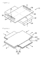
- representative schemes are a co-flow scheme in which the fuel and the oxidizing agent are introduced in the same direction as illustrated in FIG. 1 , a counter-flow scheme in which the fuel and the oxidizing agent are introduced in opposite directions as illustrated in FIG. 2 , and a cross-flow scheme in which the fuel and the oxidizing agent are introduced in directions perpendicular to each other as illustrated in FIG. 3 .
- the flow directions and operating conditions (load, utilization rate and the like) of the fuel and the oxidizing agent in the conventional fuel cell 10 may be determined according to the structures, arrangements, or the like of the separators 20 and 30, and accordingly, it is determined where an electrochemical reaction occurs. Furthermore, due to the structural constraints of the separators 20 and 30 according to the related art, a portion of the fuel cell where the electrochemical reaction occurs is biased toward one side, and accordingly, the temperature gradient is also biased toward one side.
- the thermal stress distribution in the entire stack of the conventional fuel cell 10 may be asymmetrical, and accordingly, power generation efficiency may be lowered due to the non-uniform flow or biased flow of the fuel or the oxidizing agent. As such non-uniformity is continued, this consequently causes a negative effect on the structural stability of the stack during thermal cycling in the stack.
- a fuel cell 50 using a cross-shift flow scheme is provided to reduce non-uniformity of the overall temperature gradient by alternately forming manifold structures in odd-numbered unit cells and even-numbered unit cells.
- separators 60 of the odd-numbered unit cell 51 in which fuel or an oxidizing agent is circulated some regions of the separators are provided with intake manifolds 62 and 72 into which the fuel or the oxidizing agent is introduced and other regions thereof are provided with exhaust manifolds 64 and 74 from which the fuel or the oxidizing agent is discharged.
- separators 80 and 90 of the even -numbered unit cell 55 in which the fuel or the oxidizing agent is circulated intake manifolds 82 and 92 and exhaust
- manifolds 84 and 94 are provided to intersect those of the separators 60 and 70 of the odd-numbered unit cell 51.
- Such a fuel cell 50 using the cross-shift flow scheme may solve the issue of non-uniformity of the temperature gradient to some extent, but portions of the intake manifolds 82 and 92 and the exhaust manifolds 84 and 94 are blocked in corresponding cells, causing a flow distribution in a horizontal direction to be degraded. Thus, the fuel may not be uniformly supplied to the entirety of the cells, whereby the overall performance of the fuel cell 50 may be lowered.
- the conventional fuel cell 50 using the cross-shift flow scheme has sealing members 63, 73, 83 and 93 for sealing between the intake manifolds 62, 72, 82 and 92 and the exhaust manifolds 64, 74, 84 and 94
- the sealing members 63, 73, 83 and 93 may interrupt the diffusion of the fuel or the oxidizing agent in the horizontal direction while the fuel or the oxidizing agent is flowing from the intake manifolds 62, 72, 82 and 92 to a reaction surface of the cell, resulting in a flow deviation between the manifold holes and the blocked portions of the manifolds.
- the fuel cell 50 using the cross-shift flow scheme may be modified in order to allow the horizontal diffusion to be more uniform.
- a separator 60' of the odd-numbered unit cell 51 in which the fuel or the oxidizing agent is circulated may be modified to have the intake manifold 62 which is disposed in an intermediate position and exhaust manifolds 64a and 64b which are separately formed.
- a separator 80' of the even-numbered unit cell 55 in which the fuel or the oxidizing agent is circulated may be modified to have the intake manifold 82 which is disposed in an intermediate position and exhaust manifolds 84a and 84b which are separately formed.
- the intake manifold 82 and the exhaust manifolds 84a and 84b may be sealed by the sealing members 63 and 83.
- the conventional fuel cell 50 using the cross-shift flow scheme may create more uniform horizontal diffusion as the number of intake manifolds and exhaust manifolds is increased.
- an area occupied by the sealing members 63 and 83 is also increased and an effective flow area for actual flow is reduced, and accordingly, the overall reaction efficiency and fuel utilization rate may be lowered.
- the number of sealing members having the same width may be (n-1) with respect to the n number of manifolds.
- L L H ⁇ n L A ⁇ n + L S ⁇ n - 1
- the conventional fuel cell should be developed to have a structure in which the horizontal distribution of the fuel or the oxidizing agent is improved without reducing the effective flow area L of the fuel cell.
- An aspect of the present disclosure provides a separator for a fuel cell and a fuel cell including the same able to enhance the horizontal distribution of fuel or an oxidizing agent and secure an effective flow area.
- a separator for a fuel cell including: a separator body; a first intake manifold provided at one end portion of the separator body; a second intake manifold provided at the other end portion of the separator body to be partitioned from the first intake manifolds; a first exhaust manifold provided outwardly of the second intake manifold at the other end portion of the separator body; and a second exhaust manifold provided outwardly of the first intake manifold at one end portion of the separator body to be partitioned from the first exhaust manifold.
- the separator body may be provided with one or more of the first and second intake manifolds.
- the first exhaust manifold and the second exhaust manifold may be elongated in a width direction of the separator body.
- the separator body may have a circulation path between the first intake manifold and the first exhaust manifold in the interior thereof.
- a fuel cell including one or more unit cells stacked therein, wherein the unit cell may include the separator for a fuel cell as described above, the separator including a plurality of separators, and the separators for a fuel cell may be stacked to intersect perpendicularly to allow fuel or an oxidizing agent to intersect and circulate.
- the separator body may have a circulation path between the first intake manifold and the first exhaust manifold in the interior thereof.
- the circulation path may allow a gas supplied by the first intake manifold to pass between the second intake manifolds and be discharged through the first exhaust manifold.
- the second intake manifold of the separator may be connected to a first intake manifold of another separator by sealing, and the second exhaust manifold of the separator may be connected to a first exhaust manifold of another separator by sealing.
- intake and exhaust manifolds are arranged in two rows, such that a space available for the diffusion of fuel or an oxidizing agent supplied by the intake manifolds is secured, resulting in secured effective area and improved horizontal distribution, while a single exhaust manifold is provided such that biased flow, which may be caused by a flow change or the like, resulting from a reaction, is reduced.
- the fuel cell may have improvements in the reaction efficiency and utilization rate of the fuel due to the improved horizontal distribution, the secured effective area, and the reduction of biased flow.
- FIG. 10 is a plan view of a separator for a fuel cell according to an exemplary embodiment in the present disclosure.
- a fuel cell 100 may be provided with one or more unit cells stacked therein.
- the fuel cell 100 may have a stack structure in which separators and cells are alternately stacked in order of a separator, a cell, a separator, a cell and so on.
- Such a unit cell may include one or more separators 110 and 120 and may generate energy through the oxidation-reduction reaction of fuel and an oxidizing agent supplied to the separators 110 and 120.
- the separators 110 and 120 of the unit cells may be alternately stacked, wherein even-numbered separators may be connected to each other and odd-numbered separators may be connected to each other.
- the fuel cell 100 may be a solid oxide fuel cell (SOFC) by way of example.
- SOFC solid oxide fuel cell
- Such unit cells used in the fuel cell 100 may be stacked and connected to each other so as to increase the amount of voltage supplied thereto.
- the fuel cell 100 may include an electrolyte membrane provided to separate the fuel from the oxidizing agent in the separators, and an anode and a cathode provided on both sides of the separators based on the electrolyte membrane, besides the separators 110 and 120. for separately supplying and discharging the fuel and the oxidizing agent.
- the fuel cell 100 may include the separator 110 to which the fuel is supplied, and the separator 110 for fuel may be associated with the separator 120 to which the oxidizing agent is supplied.
- the separator 110 for fuel and the separator 120 for the oxidizing agent may be provided to intersect in directions perpendicular to each other, and accordingly, the fuel or the oxidizing agent may be supplied while intersecting and circulating in the directions perpendicular to each other.
- the separator 110 or 120 may include a flat plate which is a separator body having a circulation path for guiding the flow of the fuel or the oxidizing agent in the interior thereof.
- one end portions of the separator bodies of the separators 110 and 120. may be provided with first intake manifolds 112 and 122 to which a gas, namely, the fuel or the oxidizing agent is supplied.
- the other end portions of the separator bodies of the separators 110 and 120. may be provided with second intake manifolds 116 and 126 which are partitioned from the first intake manifolds 112 and 122.
- the second intake manifolds 116 and 126 may be provided at the other end portions of the separator bodies to be sealed by using a sealing member or the like, and accordingly, the second intake manifolds 116 and 126 do not supply the gases to the separators 110 and 120, but supply the gases to other separators 110 and 120 connected thereto through first intake manifolds 112 and 122 of the other separators 110 and 120.
- first exhaust manifolds 114 and 124 from which the gases supplied by the first intake manifolds 112 and 122 are discharged after passing between the second intake manifolds 116 and 126.
- one end portions of the separator bodies of the separators 110 and 120 may be provided with second exhaust manifolds 118 and 128, outwardly of the first intake manifolds 112 and 122, as spaces partitioned from the first exhaust manifolds 114 and 124.
- the second exhaust manifolds 118 and 128 may be provided outwardly of the first intake manifolds 112 and 122 at one end portions of the separator bodies of the separators 110 and 120 to be sealed by using a sealing member or the like.
- the second exhaust manifolds 118 and 128 may be connected to first exhaust manifolds 114 and 124 of other separators 110 and 120 connected thereto, and accordingly, without the discharge of the gases to the separators 110 and 120, the second exhaust manifolds 118 and 128 may be connected to the first exhaust manifolds 114 and 124 of the other separators 110 and 120 connected thereto to discharge the gases.
- one or more first intake manifolds 112 and 122 may be provided at one end portions of the separator bodies.
- two first intake manifolds 112 and 122 may be provided to be spaced apart from each other by a predetermined interval.
- first exhaust manifolds 114 and 124 may be formed at the other end portions of the separator bodies to be elongated in the width direction of the separator bodies. That is, the first exhaust manifolds 114 and 124, according to the present embodiment, may be provided in the form of a hole, and may be provided as a long slot elongated in the width direction.
- the first exhaust manifolds 114 and 124 may rapidly discharge the fuel or the oxidizing agent that has undergone an electrochemical reaction in the interior of the cell to the second exhaust manifolds 118 and 128, and the biased flow or the like may be prevented. Without the occurrence of a bottleneck phenomenon, a flow restriction may be minimized.
- the second intake manifolds 116 and 126 may be provided inwardly of the first exhaust manifolds 114 and 124 and may be connected to first intake manifolds 112 and 122 of other separators 110 and 120. Such second intake manifolds 116 and 126 may be provided as paths for supplying the fuel or the oxidizing agent to the first intake manifolds 112 and 122 of the other separators 110 and 120.
- the second exhaust manifolds 118 and 128 may be provided outwardly of the first intake manifolds 112 and 122 and may be connected to the first exhaust manifolds 114 and 124 of the other separators 110 and 120.
- both end portions of the separator bodies may be provided with the second exhaust manifolds 118 and 128 and the first intake manifolds 112 and 122 arranged in two rows and the second intake manifolds 116 and 126 and the first exhaust manifolds 114 and 124 arranged in two rows.
- the gases, namely, the fuel or the oxidizing agent, supplied by the first intake manifolds 112 and 122 may pass through spaces between the second intake manifolds 116 and 126 to be discharged through the first exhaust manifolds 114 and 124.
- the fuel may include gaseous hydrogen.
- the oxidizing agent may include gaseous oxygen.
- pure oxygen may be used as the gaseous oxygen.
- air containing oxygen may also be used.
- the separators 110 and 120 may be stacked together with adjacent other separators 110 and 120, while having the electrolyte membranes interposed therebetween.
- the fuel may be circulated to one separator 110 and the oxidizing agent may be circulated to the other separator 120.
- the electrolyte membrane may block the permeation of the fuel and the oxidizing agent, have no electronic conductivity and allow oxygen ions or hydrogen ions to be permeated therethrough.
- the hydrogen ions of the fuel or the oxygen ions of the oxidizing agent may pass through the electrolyte membrane to trigger an oxidation-reduction reaction to thereby produce water (H 2 O), and during this procedure, electrons are generated.
- Such a reaction is represented by the following chemical formula 1 or chemical formula 2: Cathode : 1 2 ⁇ O 2 + 2 ⁇ e - ⁇ O - 2 Anode : O - 2 + H 2 ⁇ H 2 ⁇ O + 2 ⁇ e - Cathode : 1 2 ⁇ O 2 + 2 ⁇ H + ⁇ H 2 ⁇ O Anode : H 2 ⁇ 2 ⁇ H + + 2 ⁇ e -
- the fuel cell 100 may improve the flow distribution in the horizontal direction, without a reduction in the effective flow area of the gases, the fuel or the oxidizing agent, supplied by the first intake manifolds 112 and 122 of the separators 110 and 120. to thereby increase the actual circulation flow.
- the fuel utilization rate and reactivity may be improved.
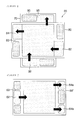
- FIG. 11 is a view illustrating a reaction region of a separator for a fuel cell according to an exemplary embodiment in the present disclosure.
- the separators 110 and 120 for the fuel cell 100 may have a reaction region formed while the gases introduced into the first intake manifolds 112 and 122 are being discharged through the first exhaust manifolds 114 and 124.
- the separators 110 and 120 may have the first intake manifolds 112 and 122 and the first exhaust manifolds 114 and 124 corresponding thereto, wherein the gas from the first intake manifolds 112 may be discharged through a single first exhaust manifold 114 and the gas from the first intake manifolds 122 may be discharged through a single first exhaust manifold 124, and may have the second intake manifolds 116 and 126 and the second exhaust manifolds 118 and 128 connected to the first intake manifolds 112 and 122 and the first exhaust manifolds 114 and 124 of other separators 110 and 120, respectively.
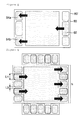
- the present inventive concept is not limited thereto, and various modifications may be made.
- the fuel or the oxidizing agent introduced into three first intake manifolds 112 or 122 of the separators 110 or 120 of the fuel cell 100, which are connected to second intake manifolds 116 or 126 of other separators 110 or 120 thereof, may be discharged through a single first exhaust manifold 114 or 124.
- the first exhaust manifolds 114 and 124 may be connected to second exhaust manifolds 118 and 128 of the other separators 110 or 120, respectively.
- the first intake manifolds 112 and 122 and the first exhaust manifolds 114 and 124 may be sequentially arranged in two rows, unlike the alternate arrangement according to the related art, such that the fuel or the oxidizing agent is supplied in the front row, passes through the reaction region, and then the reacted fuel or oxidizing agent is discharged in the rear row.
- separators 110 and 120 may be provided to intersect perpendicularly, and accordingly, for example, the fuel may be circulated in one separator 110 while the oxidizing agent may be circulated in the other separator 120 in a direction perpendicular to the direction of fuel circulation.
- separators 110 and 120 may be provided with guide protrusions 119 for guiding the circulation of the fuel or the oxidizing agent.
- the connections of the manifolds provided in the fuel cell 100 are illustrated to help in visualization thereof, but are not limited thereto and may be modified in various manners.
- the manifolds may be connected below the separators.
- the first intake manifolds 112 and 122, the first exhaust manifolds 114 and 124, the second intake manifolds 126 and 128 and the second exhaust manifolds 118 and 128 of the separators 110 and 120 may be connected below other separators 110 and 120, while passing through other separators.
Landscapes
- Life Sciences & Earth Sciences (AREA)
- Engineering & Computer Science (AREA)
- Manufacturing & Machinery (AREA)
- Sustainable Development (AREA)
- Sustainable Energy (AREA)
- Chemical & Material Sciences (AREA)
- Chemical Kinetics & Catalysis (AREA)
- Electrochemistry (AREA)
- General Chemical & Material Sciences (AREA)
- Fuel Cell (AREA)
Abstract
Description
- The present disclosure relates to a separator for a fuel cell and a fuel cell including the same and, more particularly, to a separator for a fuel cell and a fuel cell including the same able to enhance the horizontal distribution of fuel or an oxidizing agent and secure an effective flow area.
- In general, fuel cells are power generation systems converting the chemical energy of fuel into electrical energy. For example, a fuel cell converts chemical energy, generated during a chemical reaction between hydrogen fuel supplied to an anode and an oxidizing agent injected into a cathode, into electrical energy.
- Such fuel cells are classified as low-temperature type fuel cells and high-temperature type fuel cells according to operating temperature and electrolyte type. A proton exchange membrane fuel cell (PEMFC) is representative of low-temperature type fuel cells and is mainly used for vehicles or the like, while a molten carbonate fuel cell (MCFC), a solid oxide fuel cell (SOFC), and a solid oxide electrolysis cell (SOEC) using a reverse reaction of SOFC are representative of high-temperature type fuel cells.
- A
fuel cell 10 is capable of continuously generating power while fuel (hydrogen) and an oxidizing agent are continuously injected thereinto, and by enhancing the utilization rate of fuel in consideration of power generation efficiency and economical efficiency, such a fuel cell may have increased commercial value. -
Separators conventional fuel cell 10 includeflat plates flat plates exhaust manifolds flat plates intake manifolds Such separators fuel cell 10 are alternately stacked to form a stack. - Meanwhile,
conventional fuel cells 10 are classified according to a variety of schemes on the basis of arrangements of theseparators FIG. 1 , a counter-flow scheme in which the fuel and the oxidizing agent are introduced in opposite directions as illustrated inFIG. 2 , and a cross-flow scheme in which the fuel and the oxidizing agent are introduced in directions perpendicular to each other as illustrated inFIG. 3 . - The flow directions and operating conditions (load, utilization rate and the like) of the fuel and the oxidizing agent in the
conventional fuel cell 10 may be determined according to the structures, arrangements, or the like of theseparators separators - Therefore, the thermal stress distribution in the entire stack of the
conventional fuel cell 10 may be asymmetrical, and accordingly, power generation efficiency may be lowered due to the non-uniform flow or biased flow of the fuel or the oxidizing agent. As such non-uniformity is continued, this consequently causes a negative effect on the structural stability of the stack during thermal cycling in the stack. - In this regard, as illustrated in
FIGS. 4 through 6 , a cross-shift flow scheme has recently been suggested in order to solve the structural constraints in the co-flow scheme, the counter-flow scheme, and the cross-flow scheme. - A
fuel cell 50 using a cross-shift flow scheme is provided to reduce non-uniformity of the overall temperature gradient by alternately forming manifold structures in odd-numbered unit cells and even-numbered unit cells. - That is, in
separators 60 of the odd-numberedunit cell 51 in which fuel or an oxidizing agent is circulated, some regions of the separators are provided withintake manifolds exhaust manifolds - In addition, in
separators unit cell 55 in which the fuel or the oxidizing agent is circulated,intake manifolds -
manifolds 84 and 94 are provided to intersect those of theseparators unit cell 51. - Such a
fuel cell 50 using the cross-shift flow scheme may solve the issue of non-uniformity of the temperature gradient to some extent, but portions of theintake manifolds exhaust manifolds 84 and 94 are blocked in corresponding cells, causing a flow distribution in a horizontal direction to be degraded. Thus, the fuel may not be uniformly supplied to the entirety of the cells, whereby the overall performance of thefuel cell 50 may be lowered. - In this regard, a technique for allowing for uniform flow distribution throughout the entirety of the cells through the distributed arrangement of the
intake manifolds exhaust manifolds 84 and 94 has been developed. - However, since the
conventional fuel cell 50 using the cross-shift flow scheme has sealingmembers intake manifolds exhaust manifolds members intake manifolds - Meanwhile, the
fuel cell 50 using the cross-shift flow scheme may be modified in order to allow the horizontal diffusion to be more uniform. For example, a separator 60' of the odd-numberedunit cell 51 in which the fuel or the oxidizing agent is circulated may be modified to have theintake manifold 62 which is disposed in an intermediate position andexhaust manifolds - In addition, for example, a separator 80' of the even-numbered
unit cell 55 in which the fuel or the oxidizing agent is circulated may be modified to have theintake manifold 82 which is disposed in an intermediate position andexhaust manifolds exhaust manifolds members - Meanwhile, referring to
FIG. 9 , theconventional fuel cell 50 using the cross-shift flow scheme may create more uniform horizontal diffusion as the number of intake manifolds and exhaust manifolds is increased. However, an area occupied by the sealingmembers - That is, when LH denotes the width of the intake manifold and the exhaust manifold and LS denotes the width of the sealing member, the number of sealing members having the same width may be (n-1) with respect to the n number of manifolds.
- The width L of the effective flow area of the fuel cell is represented by the following equation 1:

- Therefore, the conventional fuel cell should be developed to have a structure in which the horizontal distribution of the fuel or the oxidizing agent is improved without reducing the effective flow area L of the fuel cell.
- An aspect of the present disclosure provides a separator for a fuel cell and a fuel cell including the same able to enhance the horizontal distribution of fuel or an oxidizing agent and secure an effective flow area.
- According to an aspect of the present disclosure, there is provided a separator for a fuel cell, including: a separator body; a first intake manifold provided at one end portion of the separator body; a second intake manifold provided at the other end portion of the separator body to be partitioned from the first intake manifolds; a first exhaust manifold provided outwardly of the second intake manifold at the other end portion of the separator body; and a second exhaust manifold provided outwardly of the first intake manifold at one end portion of the separator body to be partitioned from the first exhaust manifold.
- The separator body may be provided with one or more of the first and second intake manifolds.
- The first exhaust manifold and the second exhaust manifold may be elongated in a width direction of the separator body.
- The separator body may have a circulation path between the first intake manifold and the first exhaust manifold in the interior thereof.
- According to another aspect of the present disclosure , there is provided a fuel cell including one or more unit cells stacked therein, wherein the unit cell may include the separator for a fuel cell as described above, the separator including a plurality of separators, and the separators for a fuel cell may be stacked to intersect perpendicularly to allow fuel or an oxidizing agent to intersect and circulate.
- The separator body may have a circulation path between the first intake manifold and the first exhaust manifold in the interior thereof.
- The circulation path may allow a gas supplied by the first intake manifold to pass between the second intake manifolds and be discharged through the first exhaust manifold.
- The second intake manifold of the separator may be connected to a first intake manifold of another separator by sealing, and the second exhaust manifold of the separator may be connected to a first exhaust manifold of another separator by sealing.
- According to an exemplary embodiment in the present disclosure, intake and exhaust manifolds are arranged in two rows, such that a space available for the diffusion of fuel or an oxidizing agent supplied by the intake manifolds is secured, resulting in secured effective area and improved horizontal distribution, while a single exhaust manifold is provided such that biased flow, which may be caused by a flow change or the like, resulting from a reaction, is reduced. Accordingly, the fuel cell, according to the present embodiment, may have improvements in the reaction efficiency and utilization rate of the fuel due to the improved horizontal distribution, the secured effective area, and the reduction of biased flow.
-
-
FIG. 1 is a view illustrating the operation of a fuel cell using a co-flow scheme according to the related art; -
FIG. 2 is a view illustrating the operation of a fuel cell using a counter-flow scheme according to the related art; -
FIG. 3 is a view illustrating the operation of a fuel cell using a cross-flow scheme according to the related art; -
FIG. 4 is a perspective view of a fuel cell using a cross-shift flow scheme according to the related art; -
FIG. 5 is a plan view of an odd-numbered separator of a fuel cell using a cross-shift flow scheme according to the related art; -
FIG. 6 is a plan view of an even-numbered separator of a fuel cell using a cross-shift flow scheme according to the related art; -
FIG. 7 is a plan view of a modified separator of a fuel cell using a cross-shift flow scheme according to the related art; -
FIG. 8 is a plan view of another modified separator of a fuel cell using a cross-shift flow scheme according to the related art; -
FIG. 9 is a view illustrating an effective flow area of a fuel cell using a cross-shift flow scheme according to the related art; -
FIG. 10 is a plan view of a separator for a fuel cell according to an exemplary embodiment in the present disclosure; -
FIG. 11 is a view illustrating a reaction region of a separator for a fuel cell according to an exemplary embodiment in the present disclosure; and -
FIG. 12 is a plan view of a separator for a fuel cell according to another exemplary embodiment in the present disclosure. - Hereinafter, embodiments of the present disclosure will be described in detail with reference to the accompanying drawings. The disclosure may, however, be exemplified in many different forms and should not be construed as being limited to the specific embodiments set forth herein. In the drawings, the shapes and dimensions of elements may be exaggerated for clarity, and the same reference numerals will be used throughout to designate the same or like elements.
-
FIG. 10 is a plan view of a separator for a fuel cell according to an exemplary embodiment in the present disclosure. - Referring to
FIG. 10 , afuel cell 100 according to the present embodiment may be provided with one or more unit cells stacked therein. For example, thefuel cell 100 may have a stack structure in which separators and cells are alternately stacked in order of a separator, a cell, a separator, a cell and so on. - Such a unit cell may include one or
more separators separators - In the
fuel cell 100 according to the present embodiment theseparators - In addition, the
fuel cell 100 according to the present embodiment may be a solid oxide fuel cell (SOFC) by way of example. - Such unit cells used in the
fuel cell 100 may be stacked and connected to each other so as to increase the amount of voltage supplied thereto. - The
fuel cell 100 may include an electrolyte membrane provided to separate the fuel from the oxidizing agent in the separators, and an anode and a cathode provided on both sides of the separators based on the electrolyte membrane, besides theseparators - More specifically, the
fuel cell 100 according to the present embodiment may include theseparator 110 to which the fuel is supplied, and theseparator 110 for fuel may be associated with theseparator 120 to which the oxidizing agent is supplied. - The
separator 110 for fuel and theseparator 120 for the oxidizing agent may be provided to intersect in directions perpendicular to each other, and accordingly, the fuel or the oxidizing agent may be supplied while intersecting and circulating in the directions perpendicular to each other. - Meanwhile, the
separator - In addition, one end portions of the separator bodies of the
separators first intake manifolds - Furthermore, the other end portions of the separator bodies of the
separators second intake manifolds first intake manifolds second intake manifolds second intake manifolds separators other separators first intake manifolds other separators - In addition, the other end portions of the
separators first exhaust manifolds first intake manifolds second intake manifolds - Furthermore, one end portions of the separator bodies of the
separators second exhaust manifolds first intake manifolds first exhaust manifolds - In addition, the
second exhaust manifolds first intake manifolds separators second exhaust manifolds first exhaust manifolds other separators separators second exhaust manifolds first exhaust manifolds other separators - According to the present embodiment, one or more
first intake manifolds first intake manifolds - Furthermore, the
first exhaust manifolds first exhaust manifolds - Therefore, the
first exhaust manifolds second exhaust manifolds - Meanwhile, the
second intake manifolds first exhaust manifolds first intake manifolds other separators second intake manifolds first intake manifolds other separators - In addition, the
second exhaust manifolds first intake manifolds first exhaust manifolds other separators - As described above, according to the present embodiment, both end portions of the separator bodies may be provided with the
second exhaust manifolds first intake manifolds second intake manifolds first exhaust manifolds - Therefore, the gases, namely, the fuel or the oxidizing agent, supplied by the
first intake manifolds second intake manifolds first exhaust manifolds - Meanwhile, according to the present embodiment, the fuel may include gaseous hydrogen. In addition, the oxidizing agent may include gaseous oxygen.
- Furthermore, pure oxygen may be used as the gaseous oxygen. In the present embodiment, air containing oxygen may also be used.
- Meanwhile, according to the present embodiment, the
separators other separators - At this time, the fuel may be circulated to one
separator 110 and the oxidizing agent may be circulated to theother separator 120. Here, the electrolyte membrane may block the permeation of the fuel and the oxidizing agent, have no electronic conductivity and allow oxygen ions or hydrogen ions to be permeated therethrough. - Therefore, through an electrochemical reaction between the fuel passing through one cell and the oxidizing agent passing through the other cell, the hydrogen ions of the fuel or the oxygen ions of the oxidizing agent may pass through the electrolyte membrane to trigger an oxidation-reduction reaction to thereby produce water (H2O), and during this procedure, electrons are generated. Such a reaction is represented by the following chemical formula 1 or chemical formula 2:


- The
fuel cell 100, according to the exemplary embodiment, may improve the flow distribution in the horizontal direction, without a reduction in the effective flow area of the gases, the fuel or the oxidizing agent, supplied by thefirst intake manifolds separators -
FIG. 11 is a view illustrating a reaction region of a separator for a fuel cell according to an exemplary embodiment in the present disclosure. - Meanwhile, according to the present embodiment, the
separators fuel cell 100 may have a reaction region formed while the gases introduced into thefirst intake manifolds first exhaust manifolds - In the
fuel cell 100 according to the exemplary embodiment, theseparators first intake manifolds first exhaust manifolds first intake manifolds 112 may be discharged through a singlefirst exhaust manifold 114 and the gas from thefirst intake manifolds 122 may be discharged through a singlefirst exhaust manifold 124, and may have thesecond intake manifolds second exhaust manifolds first intake manifolds first exhaust manifolds other separators - For example, referring to
FIG. 12 , the fuel or the oxidizing agent introduced into threefirst intake manifolds separators fuel cell 100, which are connected tosecond intake manifolds other separators first exhaust manifold first exhaust manifolds second exhaust manifolds other separators - As described above, according to the present embodiment, the
first intake manifolds first exhaust manifolds - In addition, the
separators separator 110 while the oxidizing agent may be circulated in theother separator 120 in a direction perpendicular to the direction of fuel circulation. - Furthermore, the
separators guide protrusions 119 for guiding the circulation of the fuel or the oxidizing agent. - Meanwhile, according to the present embodiment, the connections of the manifolds provided in the
fuel cell 100 are illustrated to help in visualization thereof, but are not limited thereto and may be modified in various manners. For example, the manifolds may be connected below the separators. Specifically, thefirst intake manifolds first exhaust manifolds second intake manifolds second exhaust manifolds separators other separators - While exemplary embodiments have been shown and described above, it will be apparent to those skilled in the art that modifications and variations could be made without departing from the scope of the present invention as defined by the appended claims.
Claims (8)
- A separator for a fuel cell, comprising:a separator body;a first intake manifold provided at one end portion of the separator body;a second intake manifold provided at the other end portion of the separator body to be partitioned from the first intake manifold;a first exhaust manifold provided outwardly of the second intake manifold at the other end portion of the separator body; anda second exhaust manifold provided outwardly of the first intake manifold at one end portion of the separator body to be partitioned from the first exhaust manifold.
- The separator for a fuel cell of claim 1, wherein the separator body is provided with one or more of the first and second intake manifolds.
- The separator for a fuel cell of claim 1, wherein the first exhaust manifold and the second exhaust manifold are elongated in a width direction of the separator body.
- The separator for a fuel cell of any one of claims 1 to 3, wherein the separator body has a circulation path between the first intake manifold and the first exhaust manifold in the interior thereof.
- A fuel cell comprising one or more unit cells stacked therein,
wherein the unit cell includes the separator for a fuel cell of any one of claims 1 to 3, the separator comprising a plurality of separators, and
the separators for a fuel cell are stacked to intersect perpendicularly to allow fuel or an oxidizing agent to intersect and circulate. - The fuel cell of claim 5, wherein the separator body has a circulation path between the first intake manifold and the first exhaust manifold in the interior thereof.
- The fuel cell of claim 6, wherein the circulation path allows a gas supplied by the first intake manifold to pass between the second intake manifolds and be discharged through the first exhaust manifold.
- The fuel cell of claim 5, wherein the second intake manifold of the separator is connected to a first intake manifold of another separator by sealing, and
the second exhaust manifold of the separator is connected to a first exhaust manifold of another separator by sealing.
Applications Claiming Priority (2)
| Application Number | Priority Date | Filing Date | Title |
|---|---|---|---|
| KR1020120152259A KR101406518B1 (en) | 2012-12-24 | 2012-12-24 | Separator and fuel cell having the same |
| PCT/KR2013/012151 WO2014104732A1 (en) | 2012-12-24 | 2013-12-24 | Separator for fuel cell, and fuel cell comprising same |
Publications (2)
| Publication Number | Publication Date |
|---|---|
| EP2937922A1 true EP2937922A1 (en) | 2015-10-28 |
| EP2937922A4 EP2937922A4 (en) | 2016-01-13 |
Family
ID=51021697
Family Applications (1)
| Application Number | Title | Priority Date | Filing Date |
|---|---|---|---|
| EP13867794.3A Withdrawn EP2937922A4 (en) | 2012-12-24 | 2013-12-24 | Separator for fuel cell, and fuel cell comprising same |
Country Status (6)
| Country | Link |
|---|---|
| US (1) | US9847546B2 (en) |
| EP (1) | EP2937922A4 (en) |
| JP (1) | JP6180545B2 (en) |
| KR (1) | KR101406518B1 (en) |
| CN (1) | CN104885274B (en) |
| WO (1) | WO2014104732A1 (en) |
Families Citing this family (6)
| Publication number | Priority date | Publication date | Assignee | Title |
|---|---|---|---|---|
| JP6870739B2 (en) * | 2017-08-10 | 2021-05-19 | 日産自動車株式会社 | Fuel cell unit structure and fuel cell unit structure control method |
| CN108417875B (en) * | 2018-02-09 | 2020-07-14 | 广东国鸿氢能科技有限公司 | Distribution manifold and fuel cell stack group |
| AU2019388977B2 (en) | 2018-11-30 | 2025-01-30 | ExxonMobil Technology and Engineering Company | Flow field baffle for molten carbonate fuel cell cathode |
| CN110233278B (en) * | 2019-07-17 | 2024-06-11 | 新源动力股份有限公司 | A fuel cell stack module fluid distribution structure |
| AU2019476338B2 (en) | 2019-11-26 | 2024-04-04 | ExxonMobil Technology and Engineering Company | Fuel cell module assembly and systems using same |
| US12334607B2 (en) * | 2019-11-26 | 2025-06-17 | ExxonMobil Technology and Engineering Company | Fuel cell assembly with external manifold for parallel flow |
Family Cites Families (15)
| Publication number | Priority date | Publication date | Assignee | Title |
|---|---|---|---|---|
| JP3460346B2 (en) * | 1994-12-26 | 2003-10-27 | 富士電機株式会社 | Solid polymer electrolyte fuel cell |
| JP3549420B2 (en) * | 1998-12-15 | 2004-08-04 | 日野自動車株式会社 | Fuel cell stack |
| JP4516229B2 (en) | 2001-03-06 | 2010-08-04 | 本田技研工業株式会社 | Solid polymer cell assembly |
| JP3702848B2 (en) | 2002-01-10 | 2005-10-05 | 日産自動車株式会社 | Fuel cell |
| JP2004039483A (en) | 2002-07-04 | 2004-02-05 | Mitsubishi Electric Corp | Fuel cell |
| JP3918691B2 (en) * | 2002-09-11 | 2007-05-23 | 日産自動車株式会社 | Polymer electrolyte fuel cell |
| CA2458139A1 (en) * | 2003-02-20 | 2004-08-20 | Matsushita Electric Industrial Co., Ltd. | Polymer electrolyte fuel cell |
| CA2522731C (en) * | 2003-05-16 | 2013-03-19 | Hydrogenics Corporation | Flow field plate for a fuel cell and fuel cell assembly incorporating the flow field plate |
| JP4899339B2 (en) | 2005-05-16 | 2012-03-21 | トヨタ自動車株式会社 | Fuel cell separator |
| JP2007317525A (en) | 2006-05-26 | 2007-12-06 | Nippon Telegr & Teleph Corp <Ntt> | SOFC cell stack |
| JP5082467B2 (en) | 2007-01-29 | 2012-11-28 | トヨタ自動車株式会社 | Fuel cell and separator constituting fuel cell |
| JP2009026524A (en) * | 2007-07-18 | 2009-02-05 | Toyota Motor Corp | Fuel cell module and fuel cell |
| JP2011096498A (en) | 2009-10-29 | 2011-05-12 | Toyota Motor Corp | Fuel cell laminate |
| KR101238886B1 (en) | 2010-12-28 | 2013-03-04 | 주식회사 포스코 | Fuel cell systems and stacks |
| US8927170B2 (en) * | 2011-05-16 | 2015-01-06 | Daimler Ag | Flow field plate for reduced pressure drop in coolant |
-
2012
- 2012-12-24 KR KR1020120152259A patent/KR101406518B1/en active Active
-
2013
- 2013-12-24 CN CN201380067549.6A patent/CN104885274B/en not_active Expired - Fee Related
- 2013-12-24 JP JP2015549279A patent/JP6180545B2/en not_active Expired - Fee Related
- 2013-12-24 US US14/654,840 patent/US9847546B2/en not_active Expired - Fee Related
- 2013-12-24 EP EP13867794.3A patent/EP2937922A4/en not_active Withdrawn
- 2013-12-24 WO PCT/KR2013/012151 patent/WO2014104732A1/en not_active Ceased
Also Published As
| Publication number | Publication date |
|---|---|
| KR101406518B1 (en) | 2014-06-12 |
| JP2016506048A (en) | 2016-02-25 |
| US20150340723A1 (en) | 2015-11-26 |
| US9847546B2 (en) | 2017-12-19 |
| WO2014104732A1 (en) | 2014-07-03 |
| JP6180545B2 (en) | 2017-08-16 |
| CN104885274A (en) | 2015-09-02 |
| EP2937922A4 (en) | 2016-01-13 |
| CN104885274B (en) | 2017-10-17 |
Similar Documents
| Publication | Publication Date | Title |
|---|---|---|
| US9905880B2 (en) | Fuel cell stack | |
| KR102015482B1 (en) | Internally reforming fuel cell assembly with staged fuel flow and selective catalyst loading for improved temperature uniformity and efficiency | |
| US9847546B2 (en) | Separator for fuel cell and fuel cell including the same | |
| US7820315B2 (en) | Fuel cell stack having coolant passage whose lower area has larger flow resistance | |
| JP6093452B2 (en) | Fuel cell stack and fuel cell module | |
| CN101335358B (en) | The fuel cell | |
| KR101240976B1 (en) | Refrigerant system of fuel cell for vehicle | |
| US7618735B2 (en) | Fuel cell with triangular buffers | |
| US6926985B2 (en) | Fuel cell stack | |
| US9680164B2 (en) | Current collector for fuel cell and stack structure including the same | |
| CN111788730B (en) | Fuel cell, cell unit thereof, and stack structure | |
| KR102076865B1 (en) | Stack structure for fuel cell and components thereof | |
| KR102540924B1 (en) | Fuel cell stack | |
| CN215266397U (en) | Direct methanol fuel cell stack | |
| EP2643876B1 (en) | Co-flow / counter-flow fuel cell or electrolysis cell | |
| US8053125B2 (en) | Fuel cell having buffer and seal for coolant | |
| KR102098628B1 (en) | The separator for fuel cell | |
| US9634340B2 (en) | Plate-style water vapor transfer unit with integral headers | |
| JP2011210440A (en) | Fuel cell | |
| US7691516B2 (en) | Fuel cell system and stack used therein | |
| KR101360733B1 (en) | Fuel cell | |
| KR20240028148A (en) | Separator for feul cell | |
| KR101544402B1 (en) | Separator assembly for fuel cell | |
| JP2001202974A (en) | Polymer electrolyte fuel cell stack | |
| JPH02253564A (en) | Molten carbonate fuel cell |
Legal Events
| Date | Code | Title | Description |
|---|---|---|---|
| PUAI | Public reference made under article 153(3) epc to a published international application that has entered the european phase |
Free format text: ORIGINAL CODE: 0009012 |
|
| 17P | Request for examination filed |
Effective date: 20150721 |
|
| AK | Designated contracting states |
Kind code of ref document: A1 Designated state(s): AL AT BE BG CH CY CZ DE DK EE ES FI FR GB GR HR HU IE IS IT LI LT LU LV MC MK MT NL NO PL PT RO RS SE SI SK SM TR |
|
| AX | Request for extension of the european patent |
Extension state: BA ME |
|
| A4 | Supplementary search report drawn up and despatched |
Effective date: 20151214 |
|
| RIC1 | Information provided on ipc code assigned before grant |
Ipc: H01M 8/24 20060101ALI20151208BHEP Ipc: H01M 8/10 20060101ALN20151208BHEP Ipc: H01M 8/02 20060101AFI20151208BHEP Ipc: H01M 8/04 20060101ALI20151208BHEP |
|
| DAX | Request for extension of the european patent (deleted) | ||
| STAA | Information on the status of an ep patent application or granted ep patent |
Free format text: STATUS: EXAMINATION IS IN PROGRESS |
|
| 17Q | First examination report despatched |
Effective date: 20161221 |
|
| GRAP | Despatch of communication of intention to grant a patent |
Free format text: ORIGINAL CODE: EPIDOSNIGR1 |
|
| STAA | Information on the status of an ep patent application or granted ep patent |
Free format text: STATUS: GRANT OF PATENT IS INTENDED |
|
| RIC1 | Information provided on ipc code assigned before grant |
Ipc: H01M 8/1018 20160101ALN20180315BHEP Ipc: H01M 8/04082 20160101ALI20180315BHEP Ipc: H01M 8/04089 20160101ALI20180315BHEP Ipc: H01M 8/0202 20160101AFI20180315BHEP |
|
| INTG | Intention to grant announced |
Effective date: 20180329 |
|
| RIC1 | Information provided on ipc code assigned before grant |
Ipc: H01M 8/04082 20160101ALI20180319BHEP Ipc: H01M 8/1018 20160101ALN20180319BHEP Ipc: H01M 8/04089 20160101ALI20180319BHEP Ipc: H01M 8/0202 20160101AFI20180319BHEP |
|
| STAA | Information on the status of an ep patent application or granted ep patent |
Free format text: STATUS: THE APPLICATION IS DEEMED TO BE WITHDRAWN |
|
| 18D | Application deemed to be withdrawn |
Effective date: 20180809 |
|
| RIC1 | Information provided on ipc code assigned before grant |
Ipc: H01M 8/0202 20160101AFI20180319BHEP Ipc: H01M 8/04089 20160101ALI20180319BHEP Ipc: H01M 8/1018 20160101ALN20180319BHEP Ipc: H01M 8/04082 20160101ALI20180319BHEP |