EP2937596A1 - Shock absorber - Google Patents
Shock absorber Download PDFInfo
- Publication number
- EP2937596A1 EP2937596A1 EP15161259.5A EP15161259A EP2937596A1 EP 2937596 A1 EP2937596 A1 EP 2937596A1 EP 15161259 A EP15161259 A EP 15161259A EP 2937596 A1 EP2937596 A1 EP 2937596A1
- Authority
- EP
- European Patent Office
- Prior art keywords
- flow path
- pilot
- oil
- main
- piston
- Prior art date
- Legal status (The legal status is an assumption and is not a legal conclusion. Google has not performed a legal analysis and makes no representation as to the accuracy of the status listed.)
- Granted
Links
Images






Classifications
-
- F—MECHANICAL ENGINEERING; LIGHTING; HEATING; WEAPONS; BLASTING
- F16—ENGINEERING ELEMENTS AND UNITS; GENERAL MEASURES FOR PRODUCING AND MAINTAINING EFFECTIVE FUNCTIONING OF MACHINES OR INSTALLATIONS; THERMAL INSULATION IN GENERAL
- F16F—SPRINGS; SHOCK-ABSORBERS; MEANS FOR DAMPING VIBRATION
- F16F9/00—Springs, vibration-dampers, shock-absorbers, or similarly-constructed movement-dampers using a fluid or the equivalent as damping medium
- F16F9/32—Details
- F16F9/50—Special means providing automatic damping adjustment, i.e. self-adjustment of damping by particular sliding movements of a valve element, other than flexions or displacement of valve discs; Special means providing self-adjustment of spring characteristics
- F16F9/512—Means responsive to load action, i.e. static load on the damper or dynamic fluid pressure changes in the damper, e.g. due to changes in velocity
-
- B—PERFORMING OPERATIONS; TRANSPORTING
- B62—LAND VEHICLES FOR TRAVELLING OTHERWISE THAN ON RAILS
- B62K—CYCLES; CYCLE FRAMES; CYCLE STEERING DEVICES; RIDER-OPERATED TERMINAL CONTROLS SPECIALLY ADAPTED FOR CYCLES; CYCLE AXLE SUSPENSIONS; CYCLE SIDECARS, FORECARS, OR THE LIKE
- B62K25/00—Axle suspensions
- B62K25/04—Axle suspensions for mounting axles resiliently on cycle frame or fork
- B62K25/06—Axle suspensions for mounting axles resiliently on cycle frame or fork with telescopic fork, e.g. including auxiliary rocking arms
- B62K25/08—Axle suspensions for mounting axles resiliently on cycle frame or fork with telescopic fork, e.g. including auxiliary rocking arms for front wheel
-
- F—MECHANICAL ENGINEERING; LIGHTING; HEATING; WEAPONS; BLASTING
- F16—ENGINEERING ELEMENTS AND UNITS; GENERAL MEASURES FOR PRODUCING AND MAINTAINING EFFECTIVE FUNCTIONING OF MACHINES OR INSTALLATIONS; THERMAL INSULATION IN GENERAL
- F16F—SPRINGS; SHOCK-ABSORBERS; MEANS FOR DAMPING VIBRATION
- F16F9/00—Springs, vibration-dampers, shock-absorbers, or similarly-constructed movement-dampers using a fluid or the equivalent as damping medium
- F16F9/10—Springs, vibration-dampers, shock-absorbers, or similarly-constructed movement-dampers using a fluid or the equivalent as damping medium using liquid only; using a fluid of which the nature is immaterial
- F16F9/14—Devices with one or more members, e.g. pistons, vanes, moving to and fro in chambers and using throttling effect
- F16F9/16—Devices with one or more members, e.g. pistons, vanes, moving to and fro in chambers and using throttling effect involving only straight-line movement of the effective parts
- F16F9/18—Devices with one or more members, e.g. pistons, vanes, moving to and fro in chambers and using throttling effect involving only straight-line movement of the effective parts with a closed cylinder and a piston separating two or more working spaces therein
-
- F—MECHANICAL ENGINEERING; LIGHTING; HEATING; WEAPONS; BLASTING
- F16—ENGINEERING ELEMENTS AND UNITS; GENERAL MEASURES FOR PRODUCING AND MAINTAINING EFFECTIVE FUNCTIONING OF MACHINES OR INSTALLATIONS; THERMAL INSULATION IN GENERAL
- F16F—SPRINGS; SHOCK-ABSORBERS; MEANS FOR DAMPING VIBRATION
- F16F9/00—Springs, vibration-dampers, shock-absorbers, or similarly-constructed movement-dampers using a fluid or the equivalent as damping medium
- F16F9/32—Details
- F16F9/44—Means on or in the damper for manual or non-automatic adjustment; such means combined with temperature correction
- F16F9/46—Means on or in the damper for manual or non-automatic adjustment; such means combined with temperature correction allowing control from a distance, i.e. location of means for control input being remote from site of valves, e.g. on damper external wall
- F16F9/465—Means on or in the damper for manual or non-automatic adjustment; such means combined with temperature correction allowing control from a distance, i.e. location of means for control input being remote from site of valves, e.g. on damper external wall using servo control, the servo pressure being created by the flow of damping fluid, e.g. controlling pressure in a chamber downstream of a pilot passage
Definitions
- the present invention relates to a shock absorber which includes a damping force adjusting apparatus which controls a flow of an internal working fluid generated according to extension and contraction motions and adjusts a damping force.
- a shock absorber which is used as a front fork which suspends a front wheel of a motorcycle to a vehicle body, includes a cylinder in which an oil serving as a working fluid is enclosed, a piston which is slidably fitted into the cylinder, a piston rod which is connected to the piston and extends outside the cylinder, and a damping force adjusting apparatus which controls a flow of oil by sliding of the piston in the cylinder and adjusts the damping force.
- a damping force adjusting apparatus which largely changes damping force characteristics in a medium-high speed region of a piston speed
- a pilot chamber is formed on a rear portion of a disc valve which selectively opens and closes an oil path provided in the piston
- the pilot chamber communicates with a cylinder chamber in an upstream side of the disc valve via a fixed orifice and communicates with a cylinder chamber in a downstream side of the disc valve via a variable orifice
- a passage area between two chambers in the cylinder is adjusted by opening and closing the variable orifice, a pressure (back pressure) of the pilot chamber is changed by a pressure loss generated in the variable valve, and thus, it is possible to adjust a valve opening pressure of the disc valve. Accordingly, it is possible to widen an adjustment range of the damping force characteristics.
- Patent Literature 2 JP-A-H10-246271 ) suggests a damping force adjusting apparatus which adopts a configuration in which an outer circumferential edge of a disc valve 201 is bent to a valve seat 202 side and a guide portion 201 a is formed.
- a jet stream of a working fluid passing through a gap between the disc valve 201 and the valve seat 202 when the valve is opened is ejected at an ejection angle ⁇ along an outer circumferential portion of the valve seat 202 toward a gap between the valve seat 202 and the guide portion 201 a of the disc valve 201. Accordingly, the force in the valve closing direction which acts on the disc valve 201 is decreased, and particularly, it is possible to prevent an excessive damping force in the medium-high speed region of the piston speed from being generated.
- an object of the present invention is to provide a shock absorber capable of obtaining a desired damping force characteristic by widening the adjustment range of the damping force in the medium-high speed region of the piston speed.
- a shock absorber including: a cylinder in which a working fluid is enclosed; a piston which is slidably fitted in the cylinder; a piston rod which is connected to the piston and extends outside the cylinder; and a damping force generating apparatus which generates a damping force by controlling a flow of the working fluid caused by sliding of the piston in the cylinder, in which the damping force generating apparatus includes: a main flow path through which the working fluid flows by the sliding of the piston in the cylinder; a main valve which generates the damping force by controlling the flow of the working fluid by opening and closing the main flow path; a bypass flow path which is branched from the main flow path or is provided on the main valve; a pilot chamber into which the working fluid flows via the bypass flow path and which applies an internal pressure in a valve closing direction to the main valve by a pressure of the working fluid; and a pilot flow path to which the working fluid flows out from the pilot chamber, wherein a jet stream which is generated in
- a shock absorber including: a cylinder in which a working fluid is enclosed; a piston which is slidably fitted in the cylinder; a piston rod which is connected to the piston and extends outside the cylinder; and a damping force generating apparatus which generates a damping force by controlling a flow of the working fluid caused by sliding of the piston in the cylinder, in which the damping force generating apparatus includes: a main flow path through which the working fluid flows by the sliding of the piston in the cylinder; a main valve which generates the damping force by controlling the flow of the working fluid by opening and closing the main flow path; a bypass flow path which is branched from the main flow path or is provided on the main valve; a pilot chamber into which the working fluid flows via the bypass flow path and which applies an internal pressure in a valve closing direction to the main valve by a pressure of the working fluid; and a pilot flow path to which the working fluid flows out from the pilot chamber, wherein a jet stream which is generated by
- the flow of the working fluid flowing out from the pilot chamber via the pilot flow path may join the jet stream in a same direction as a flow of the jet stream flowing through the main flow path.
- the flow of the working fluid flowing out from the pilot chamber via the pilot flow path may join the jet stream in a direction opposite to a flow of the jet stream flowing through the main flow path.
- the shock absorber may further include a shielding member which shields at least one of the flow of the working fluid flowing out from the pilot chamber via the pilot flow path and the flow of the jet stream flowing through the main flow path, in which the shielding member is provided in a location at which the flow of the working fluid flowing out from the pilot chamber via the pilot flow path joins the jet stream flowing through the main flow path.
- the shock absorber may further include a flow changing member which changes a direction of at least one of the flow of the working fluid flowing out from the pilot chamber via the pilot flow path and the flow of the jet stream flowing through the main flow path, in which the flow changing member is provided in a location at which the flow of the working fluid flowing out from the pilot chamber via the pilot flow path joins the jet stream flowing through the main flow path.
- the damping force generating apparatus may be provided inside the piston.
- the damping force generating apparatus may be provided outside the piston.
- the jet stream which is generated in the flow path narrowed by the main valve in the main flow path joins the flow of the working fluid which flows out from the pilot chamber via the pilot flow path.
- the jet stream which is generated by narrowing the entire main flow path or a partial flow path of the main flow path other than a location at which the main valve is disposed joins the flow of the working fluid which flows out from the pilot chamber via the pilot flow path.
- the flow of the working fluid which flows out from the pilot chamber via the pilot flow path is adjusted by a force of the jet stream flowing through the main flow path.
- the jet stream joins the flow of the working fluid which flows out from the pilot chamber via the pilot flow path.
- a back pressure of the pilot chamber is also adjusted using the jet stream of the working fluid which flows through the main valve of the main flow path. Therefore, it is also possible to adjust a pressurizing force in a valve closing direction which acts on the main valve using the jet stream, and thus, it is possible to adjust a desired damping force.
- the flow of the working fluid flowing out from the pilot chamber via the pilot flow path joins in the same direction as the jet stream flowing through the main flow path. Accordingly, in a medium-high speed region of a piston speed, a sucking effect is generated in the flow of the working fluid flowing out from the pilot chamber via the pilot flow path, by the force of the jet stream flowing through the main flow path. As a result, the back pressure of the pilot chamber is decreased, the force pressing the main valve in the valve closing direction is decreased, an opening degree of the main valve is increased, and thus, it is possible to prevent the damping force in the medium-high speed region of the piston speed from being increased.
- the flow of the working fluid which flows out from the pilot chamber via the pilot flow path joins in the direction opposite to the flow of the jet stream flowing through the main flow path. Accordingly, the flow of the working fluid flowing out from the pilot chamber via the pilot flow path collides with the jet stream flowing through the main flow path, and thus, the force of the flow of the working fluid which flows out from the pilot chamber is suppressed. As a result, the back pressure of the pilot chamber is increased, the force pressing the main valve in the valve closing direction is increased, the opening degree of the main valve is decreased, and thus, it is possible to adjust the damping force in the medium-high speed region of the piston speed so as to be increased.
- the shielding member by which at least one of the flow of the working fluid flowing out from the pilot chamber via the pilot flow path and the jet stream flowing through the main flow path is shielded is provided in the location at which the flow of the working fluid flowing out from the pilot chamber via the pilot flow path joins the jet stream flowing through the main flow path. Accordingly, the force of at least one of the flow of the working fluid which flows out from the pilot chamber via the pilot flow path and the jet stream flowing through the main flow path is suppressed by the shielding member. Accordingly, the back pressure of the pilot chamber is also adjusted. Therefore, it is also possible to adjust the pressurizing force in a valve closing direction which acts on the main valve, and thus, it is possible to adjust a desired damping force.
- the flow changing member which changes the direction in which at least one of the flow of the working fluid flowing out from the pilot flow path and the jet stream flowing through the main flow path flows is provided in the location at which the flow of the working fluid which flows out from the pilot chamber via the pilot flow path joins the jet stream flowing through the main flow path. Accordingly, the direction in which at least one of the flow of the working fluid flowing out from the pilot flow path and the jet stream flowing through the main flow path working fluid flows is changed at the location at which the flow of the working fluid which flows out from the pilot chamber via the pilot flow path joins the jet stream flowing through the main flow path, and thus, it is possible to adjust a desired damping force by adjusting the back pressure of the pilot chamber.
- the damping force generating apparatus is compactly incorporated into the piston, and for example, it is possible to use the shock absorber as a front fork or a rear cushion which suspends a wheel of a motorcycle to a vehicle body.
- the damping force generating apparatus by disposing the damping force generating apparatus outside the piston, it is possible to freely dispose the damping force generating apparatus, and thus, it is possible to increase a degree of freedom of the layout. Accordingly, it is also possible to increase the degree of freedom of the layout with respect to disposition of a solenoid serving as an actuator or wiring of a harness or the like.
- Fig. 1 is a vertical cross-sectional diagram of a main portion of a shock absorber 1 according to a first embodiment of the present invention
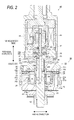
- Fig. 2 is a vertical cross-sectional diagram of a damping force generating apparatus of the shock absorber.
- the shock absorber 1 is used as an inverted front fork which suspends a front wheel of a motorcycle (not shown) to a vehicle body, and as shown in Fig. 1 , in the shock absorber 1, a portion of an inner tube 3 attached to an axle side is inserted into an outer tube 2 attached to the vehicle body side from below.
- An upper end portion of the outer tube 2 is attached to the vehicle body (steering axis) of the motorcycle by an upper bracket (not shown) and a lower bracket (not shown), and an upper end of the outer tube 2 is sealed by a cap bolt 4.
- a guide bush 5, an oil seal 6, and a dust seal 7 which comes into sliding-contact with an outer circumference of the inner tube 3 are fitted to an inner circumference of a lower end opening portion of the outer tube 2 to which the inner tube 3 penetrates.
- a hollow piston rod 8 in which an upper end is connected to the cap bolt 4 is hung down in an axial center in the outer tube 2.
- a portion of the piston rod 8 penetrates a bottomed cylindrical partition wall member 9 which is fitted to an upper end portion in the inner tube 3, and is inserted into the inner tube 3 from above.
- a solenoid 40 configuring an actuator of a damping force generating apparatus 20, a piston 21, and a spring collar 10 are connected by upper and lower nuts 11 and 12, and main portions of the damping force generating apparatus 20 are incorporated inside the piston 21.
- a power cord 13 for supplying power to the solenoid 40 is inserted into the piston rod 8.
- a rebound spring 14 is wound around the piston rod 8 on the nut 11.
- the lower end portion of the inner tube 3 is attached to a front axle of the motorcycle via an axle attachment member (not shown), and a portion of the inner tube which is inserted into the outer tube 2 is slidably held vertically with respect to the outer tube 2 by a guide bush 15 which is fitted to an upper end outer circumference of the inserted portion and a guide bush 5 which is fitted to a lower end inner circumference of the outer tube 2.
- a guide bush 15 which is fitted to an upper end outer circumference of the inserted portion
- a guide bush 5 which is fitted to a lower end inner circumference of the outer tube 2.
- an annular oil chamber S4 in which an upper end and a lower end are sealed by the guide bush 15 and the guide bush 5 is formed in a gap between the inner circumference of the outer tube 2 and the outer circumference of the inner tube 3.
- a communication hole 3a through which a rod side oil chamber S3 inside the inner tube 3 and the annular oil chamber S4 communicate with each other, is formed on a portion below the partition wall member 9 described
- a rod guide 16 to which the piston rod 8 penetrates is fitted into an axial center of a bottom portion of the partition wall member 9 fitted to an inner circumference of an upper end portion of the inner tube 3. Moreover, the piston rod 8 is slidably held vertically by the rod guide 16.
- the inner tube 3 is an example of a cylinder.
- the piston 21 is slidably fitted vertically to the inner circumference of the inner tube 3.
- An inner portion enclosed by the outer tube 2 and the inner tube 3 is partitioned vertically by the partition wall member 9, and an upper space is an oil reservoir chamber Re which functions as a reservoir.
- the oil reservoir chamber Re is configured of an oil accommodation portion Ro in which the oil is supplied from and is discharged to the rod side oil chamber S3 through the partition wall member 9 as a border, and a gas accommodation portion Rg which is filled with a gas such as air.
- a space below the partition wall member 9 inside the inner tube 3 is partitioned into the rod side oil chamber S3 and a piston side oil chamber S2 by the piston 21.
- the rod side oil chamber S3 and the piston side oil chamber S2 are filled with the oil serving as a working fluid.
- a suspension spring 17 is interposed between the bottom portion of the inner tube 3 and the spring collar 10. Moreover, leakage of the oil from the inner tube 3 is prevented by a sealing effect of the oil seal 6. Penetration of dust from the lower end opening portion of the outer tube 2 is prevented by a sealing effect of the dust seal 7.
- the main portions are incorporated into the piston 21.
- the piston 21 is divided into two portions such as an upper piston 21 A and a lower piston 21B.
- a valve stopper 22, an extension side outlet check valve 23, a lower piston 21 B, a compression side inlet check valve 24, an extension side inlet check valve 25, an upper piston 21 A, a compression side outlet check valve 26, a valve stopper 27, a valve seat member 28, and a solenoid 40 are assembled in the vertical direction (axial direction) in this order from below, and thus, the damping force generating apparatus 20 is configured.
- a rod portion 28A integrally protrudes downward from an axial center of the valve seat member 28.
- the rod portion 28A penetrates center portions in the radial directions of the valve stopper 27, the compression side outlet check valve 26, the upper piston 21 A, the extension side inlet check valve 25, the compression side inlet check valve 24, the lower piston 21 B, the extension side outlet check valve 23, and the valve stopper 22, and a nut 12 is screwed to a lower end portion of the rod portion 28A.
- a main valve member 29 which is fitted to an outer circumference of the rod portion 28A of the valve seat member 28 is accommodated in a concave portion 21 a of the lower piston 21 B.
- a main valve 30 having an approximately cylindrical shape is slidably fitted and held vertically to an outer circumference of the main valve member 29.
- An annular pilot member (back pressure chamber) 31 partitioned by the main valve member 29 is formed on a rear surface side (lower side in Fig. 2 ) of the main valve 30 of the concave portion 21 a of the main valve member 29.
- a plate spring 32 which biases the main valve 30 in an up direction (valve closing side) to seat the main valve 30 on a lower surface (seating surface) of the upper piston 21 A is accommodated in the pilot chamber 31.
- a flow path 33 is formed between the concave portion 21 a of the lower piston 21 B and the outer circumference of the main valve 30.
- the flow path 33 communicates with the pilot chamber 31 via an oil hole 30a which is formed in the main valve 30.
- a space 34 which is cut in a taper shape is formed on a lower inner circumference of the upper piston 21 A.
- An oil hole 21 b which penetrates the upper piston 21A in the vertical direction and an inclined oil hole 21 c are formed in the upper piston 21 A.
- the oil hole 21 b is normally opened to the rod side oil chamber S3 (refer to Fig. 1 ) in the inner tube 3, and is selectively opened and closed by the extension side inlet check valve 25.
- the oil hole 21 c is normally opened to the space 34, and is selectively opened and closed by the compression side outlet check valve 26.
- a space 35 which is cut in a taper shape is formed on a lower inner circumference of the lower piston 21 B.
- an oil hole 21d which penetrates the lower piston 21 B in the vertical direction and an inclined oil hole 21 e are formed in the lower piston 21 B.
- the oil hole 21 d is normally opened to the piston side oil chamber S2 (refer to Fig. 1 ) formed in the inner tube 3, and is selectively opened and closed by the compression side inlet check valve 24.
- the oil hole 21 e is normally opened to the space 35, and is selectively opened and closed by the extension side outlet check valve 23.
- a concave portion 28a which is opened upward is formed on an axial center upper portion of the valve seat member 28.
- An oil hole 28b is formed downward in the axial center of the rod portion 28A from the concave portion 28a.
- an oil hole 28c is formed outward in the radial direction from a lower end portion of the oil hole 28b at a light angle.
- the oil hole 28c communicates with the pilot chamber 31 via an oil hole (not shown) which is formed on the main valve member 29 in the radial direction.
- a plurality of oil holes 29a which penetrate in the axial direction are formed on the main valve member 29.
- One end (upper end) of the oil hole 29a communicates with the oil hole 21 c of the upper piston 21 A via the space 34 of the upper piston 21 A, and the other end (lower end) communicates with the oil hole 21 e of the lower piston 21 B via the space 35 of the lower piston 21 B.
- a gap 37 in the vertical direction is formed between the upper piston 21 A and the lower piston 21 B by an annular distance collar 36 which is fitted to outer circumferences of both pistons 21 A and 21 B.
- the compression side inlet check valve 24 and the extension side inlet check valve 25 are provided in the gap 37.
- the compression side inlet check valve 24 and the extension side inlet check valve 25 are biased in the direction, in which the oil hole 21d of the lower piston 21 B and the oil hole 21 b of the upper piston 21 A are closed, by a plate spring 38 interposed between the check valves 24 and 25.
- the solenoid 40 is configured to accommodate two bottomed cylindrical cores 42 and 43, an annular coil 44, a plunger 45 accommodated in the cores 42 and 43, a hollow operating rod 46 which penetrates an axial center of the plunger 45, and so on inside a cylindrical casing 41 in which a lower end opening inner circumference is screwed to the outer circumference of the valve seat member 28. Both end portions in the vertical direction of the operating rod 46 are supported to be movable in the vertical direction by cylindrical guide bushes 47 and 48.
- a pilot valve 49 is connected to a lower end outer circumference of the operating rod 46 facing the concave portion 28a of the valve seat member 28.
- the pilot valve 49 is fitted to the inner circumference of the concave portion 28a of the valve seat member 28 to be movable in the vertical direction, is selectively seated on a tapered valve seat 28d formed on an upper end of the oil hole 28b formed in the axial center of the valve seat member 28, and thus, opens and closes the oil hole 28b.
- a space 50 which is partitioned by the pilot valve 49 is formed in the concave portion 28a of the valve seat member 28.
- a spring 51 which biases the pilot valve 49 in a valve opening direction (up direction in Fig. 2 ) is accommodated in the space 50.
- the space 50 formed in the valve seat member 28 communicates with the pilot chamber 31 via the oil holes 28b and 28c of the valve seat member 28 and an oil hole (not shown) formed in the main valve member 29.
- an oil hole 49a penetrates the pilot valve 49. The oil hole 49a is normally opened to the space 50.
- a concave space 52 is formed on an end surface of the core 42 of the solenoid 40 between the valve seat member 28 and the core 42 of the solenoid 40.
- a fail-valve 53 which selectively opens and closes the oil hole 49a of the pilot valve 49 is provided in the space 52.
- the fail-valve 53 is slidably held vertically on an outer circumference of the operating rod 46, and is biased in a valve closing direction (down in Fig. 2 ) by a spring 54 accommodated in the space 52.
- a spring constant of the spring 54 is set to be smaller than a spring constant of a spring 51 which biases the pilot valve 49 in the valve opening direction.
- An oil hole 28e which penetrates in the vertical direction is formed in the valve seat member 28.
- the space 52 communicates with the space 34 of the upper piston 21 A via the oil hole 28e, a cylindrical flow path 55 formed between the valve stopper 27 and the valve seat member 28, and a cylindrical flow path 56 formed between the upper piston 21 A and the rod portion 28A of the valve seat member 28.
- a cylindrical guide portion 29A which extends to the space 34 of the upper piston 21 A toward above is formed at a center portion in the radial direction of the main valve member 29.
- a tapered guide surface 29b which is inclined toward above is formed on an inner circumferential surface of the guide portion 29A.
- the oil hole 21 d of the lower piston 21 B, the gap 37, the space 34 of the upper piston 21 A, and the oil hole 21 c of the upper piston 21 A configure a main flow path 70 at a time of a compression side stroke.
- the main valve 30, the compression side inlet check valve 24, and the compression side outlet check valve 26 are provided in the main flow path 70.
- the oil hole 21 b of the upper piston 21 A, the gap 37, the oil hole 29a of the main valve member 29, and the oil hole 21 e of the lower piston 21 B configure a main flow path 80 at a time of an extension side stroke.
- the main valve 30, the extension side inlet check valve 25, and the extension side outlet check valve 23 are provided in the main flow path 80.
- the gap 37 between the upper piston 21 A and the lower piston 21 B, the flow path 33 formed on the outer circumferential side of the main valve 30, the oil hole 30a of the main valve 30, the pilot chamber 31, an oil hole (not shown) formed in the main valve member 29, oil holes 28c and 28b formed in the valve seat member 28, the space 50 formed by the pilot valve 49 and the valve seat member 28, the oil hole 49a formed in the pilot valve 49, the space 52 formed in the core 42 of the solenoid 40, the oil hole 28e formed in the valve seat member 28, the flow path 55 formed between the valve stopper 27 and the valve seat member 28, the flow path 56 communicating with the flow path 55, and the space 34 of the upper piston 21A configure a pilot flow path 90 for compression and extension side strokes.
- the pilot valve 49 and the fail-valve 53 are provided on the pilot flow path 90.
- the flow path 33 and the oil hole 30a of the main valve 30 also function as a bypass flow path through which a portion of the oil flowing through the main flow paths 70 and 80 is introduced to the pilot chamber 31.
- Fig. 3 is a vertical cross-sectional diagram showing a flow of oil at the time of the compression side stroke in the damping force generating apparatus of the shock absorber 1 according to the present embodiment
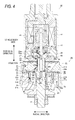
- Fig. 4 is a vertical cross-sectional diagram showing the flow of the oil at the time of the extension side stroke in the damping force generating apparatus
- Fig. 5 is a graph showing a characteristic of a damping force with respect to a piston speed.
- the oil passes through the oil hole 21 d of the lower piston 21 B from the piston side oil chamber S2, flows to the gap 37 by pushing to open the compression side inlet check valve 24 against the biasing force of the plate spring 38, flows to the oil hole 21 c of the upper piston 21 A via the space 34 from the gap 37 by pushing to open the main valve 30 against the force in the valve closing direction due to the plate spring 32 and the back pressure of the pilot chamber 31 through the pressure in the gap 37, and flows into the rod side oil chamber S3 by pushing to open the compression side outlet check valve 26.
- a compression side damping force is generated in the shock absorber 1 by a flow resistance generated when the oil passes through the main valve 30.
- a portion of the oil flowing into the gap 37 through the oil hole 21 d of the lower piston 21 B from the piston side oil chamber S2 passes through the oil hole 30a of the main valve 30 from the flow path 33 of the outer circumferential side of the main valve 30, flows into the pilot chamber 31, and flows into the space 50 of the valve seat member 28 through the oil hole (not shown) of the main valve member 29, the oil holes 28c and 28b of the valve seat member 28, and a gap between the pilot valve 49 and the valve seat 28d from the pilot chamber 31.
- the oil flowing into the space 50 of the valve seat member 28 flows into the space 52 of the core 42 by pushing to open the fail-valve 53 against a biasing force of the spring 54 through the oil hole 49a of the pilot valve 49, flows into the space 34 of the upper piston 21 A through the oil hole 28e of the valve seat member 28 and the flow paths 55 and 56 from the space 52, and joins the oil flowing through the main flow path 70 in the space 34.
- the opening degree of the pilot valve 49 when the opening degree of the pilot valve 49 is narrowed, the back pressure of the pilot chamber 31 increases, the opening degree of the main valve 30 is narrowed, and the damping force increases. Meanwhile, when the opening degree of the pilot valve 49 is largely adjusted, the opening degree of the main valve 30 increases, and the damping force is adjusted to be decreased.
- the oil flowing through the pilot flow path 90 joins the oil flowing through the main flow path 70 in the space 34 of the upper piston 21 A.
- both oils are controlled by the guide portion 29A of the main valve member 29.
- a flow of the oil of the pilot flow path 90 is referred to as a "pilot stream”
- a flow of the oil passing through the main valve 30 of the main flow path is referred to as a "jet stream”.
- the jet stream means a phenomenon in which a fluid having a speed flows in substantially one direction into a space from a small hole so as to be ejected, generally.
- the jet stream includes a case where the oil passing through the flow path is ejected by narrowing the flow path at the location at which the oil passes through the main valve 30 disposed on the main flow paths 70 and 80, a case where the oil passing though the flow path is ejected by narrowing the flow path at a location other than the location at which the main valve 30 is disposed such as a portion at which the flow of the oil passing through the main valve 30 disposed on the main flow paths 70 and 80 joins the pilot stream, and a case where a portion in which the pilot stream joins is provided on the middle of the flow having relatively high speed generated by the narrowing of the flow path.
- the oil passing through the main valve 30 of the main flow path 70 shown in Fig. 3 becomes a jet stream which is ejected toward the rod portion 28A side (from an outer side to an inner side) in the radial direction.
- a flow direction of the pilot stream is controlled by the inclined guide surface 29b of the guide portion 29A.
- a inclination direction of the guide surface 29b and a direction of the jet stream are the same as each other with the guide portion 29A as a border. Accordingly, in the compression side stroke shown in Fig. 3 , the pilot stream guided in the inclination direction of the guide surface 29b joins in the same direction as the direction of the jet stream of the oil passing through the main valve 30 of the main flow path 70.
- a sucking effect of the pilot stream is generated by a force of the flow in the jet stream of the oil passing through the main valve 30.
- the back pressure of the pilot chamber 31 decreases, a force by which the main valve 30 is pressed in the valve closing direction decreases, the opening degree of the main valve 30 increases, and thus, it is possible to prevent the compression side damping force in the medium-high speed region of the piston speed from being increased.
- Fig. 5 shows the characteristic of the damping force with respect to the piston speed.
- a dashed line B relatively with respect to a linear characteristic shown in a solid line A, it is possible to suppress a rate of increase in the compression side damping force of the medium-high speed region of the piston speed.
- the jet stream which is generated at the flow path 30b narrowed by the main valve 30 joins the pilot stream which is the flow of the oil flowing out through the pilot flow path 90 from the pilot chamber 31.
- a jet stream may be generated by narrowing the entire main flow path 70 or a partial flow path of the main flow path 70 other than a location of the flow path 30b at which the main valve 30 is disposed, and joins the pilot stream. In either case, the jet stream joins the pilot stream. Accordingly, the back pressure of the pilot chamber 31 is also adjusted using the jet stream of the oil passing through the main valve 30 of the main flow path 70. Therefore, it is also possible to adjust a pressurizing force in the valve closing direction which acts on the main valve 30, using the jet stream, and it is possible to adjust the damping force to a desired damping force.
- the guide portion 29A shown in Fig. 3 is not limited to the sucking effect of the jet stream due to the force of the flow in the above-described jet stream according to a shape of the guide portion 29A.
- the guide portion 29A may be a shielding member having an effect which further suppresses the force of the jet stream as the main object.
- the pilot stream and the back pressures of the pilot chamber 31 are also adjusted. Accordingly, it is also possible to adjust the pressurizing force in the valve closing direction which acts on the main valve 30, and it is possible to adjust the damping force to a desired damping force.
- the wall surface portion 29d shields the jet stream which is the flow of the oil flowing through the main valve 30 in the main flow path 70.
- a shielding member which suppresses the force of the pilot stream flowing out from the pilot chamber 31 via the pilot flow path 90 may be provided, and thus, the damping force may be adjusted to the desired damping force.
- the shielding member may be provided not only on either the jet stream side or the pilot stream side as described above but also on both the jet stream side and the pilot stream side, and thus, the damping force may be adjusted to the desired damping force.
- the guide portion 29A shown in Fig. 3 may be a flow changing member which changes the flow direction of the pilot stream which is the flow of the oil flowing out from the pilot chamber 31 via the pilot flow path 90.
- the guide portion 29A changes the flow direction of the pilot stream.
- a flow changing member which changes the flow direction of the jet stream which is the flow of the oil flowing through the main valve 30 in the main flow path 70 may be provided, and thus, the damping force may be adjusted to the a desired damping force.
- the flow changing member may be provided not only on either the jet stream side or the pilot stream side as described above but also on both the jet stream side and the pilot stream side, and thus, the damping force may be adjusted to a desired damping force.
- the shielding member and/or the flow changing member may be provided on the join location between the pilot stream and the jet stream or each outlet of the pilot stream and the jet stream, and the damping force may be adjusted to the desired damping force by adjusting the back pressure of the pilot chamber 31.
- the supply of the oil with respect to the shortage is performed by a supply-discharge portion (not shown) which is formed on a bottom portion of the partition wall member 9 and through which the oil is supplied from the rod side oil chamber S3 to the oil accommodation portion Ro and is discharged from the oil accommodation portion Ro to the rod side oil chamber S3.
- a supply-discharge portion (not shown) which is formed on a bottom portion of the partition wall member 9 and through which the oil is supplied from the rod side oil chamber S3 to the oil accommodation portion Ro and is discharged from the oil accommodation portion Ro to the rod side oil chamber S3.
- the oil passes through the oil hole 21 b of the upper piston 21A from the rod side oil chamber S3, flow to the gap 37 by pushing to open the extension side inlet check valve 25 against the biasing force of the plate spring 38, flows to the oil hole 29a of the main valve member 29 and the oil hole 21 e of the lower piston 21 B from the gap 37 by pushing to open the main valve 30 against the force in the valve closing direction due to the plate spring 32 and the back pressure of the pilot chamber 31 through the pressure in the gap, and flows into the piston side oil chamber S2 by pushing to open the extension side outlet check valve 23.
- an extension side damping force is generated in the shock absorber 1 by the flow resistance generated when the oil passes through the main valve 30.
- the oil flowing through the pilot flow path 90 joins the jet stream of the oil flowing through the main valve 30 of the main flow path 80 in the space 34 of the upper piston 21 A.
- the oil passing through the main valve 30 of the main flow path 80 shown in Fig. 4 becomes the jet stream which is ejected toward the rod portion 28A side (from the outer side to the inner side) in the radial direction.
- the flow direction of the pilot stream is controlled by the inclined guide surface 29b of the guide portion 29A.
- the direction of the jet stream becomes different from the inclination direction of the guide surface 29b of the guide portion 29A unlike the direction at the time of the compression side stroke. Accordingly, compared to the compression side stroke, in the extension side stroke, the influence of the sucking effect of the pilot stream by the jet stream is decreased. Therefore, the influence of the effect of suppressing the increase in the damping force in the medium-high speed region of the piston speed is also decreased.
- the case where the jet stream generated in the flow path 30b narrowed by the main valve 30 joins the pilot stream, or the case where the jet stream, which is generated by narrowing the entire main flow path 70 or a partial flow path of the main flow path 70 other than the location of the flow path 30b at which the main valve 30 is disposed, joins the pilot stream is shown.
- the case where the jet stream generated in the flow path 30b narrowed by the main valve 30 joins the pilot stream, or the case where the jet stream, which is generated by narrowing the entire main flow path 80 or a partial flow path of the main flow path 80 other than the location of the flow path 30b at which the main valve 30 is disposed, joins the pilot stream may be adopted.
- the pressurizing force in the valve closing direction acting on the main valve 30 is adjusted by having the jet stream join the pilot stream, and thus, the damping force may be adjusted to the desired damping force.
- the shielding member and/or the flow changing member is provided on the join location between the pilot stream and the jet stream or each outlet of the pilot stream and the jet stream by changing the shape of the guide portion 29A is also illustrated.
- the shielding member and/or the flow changing member may be provided on the join location between the pilot stream and the jet stream or each outlet of the pilot stream and the jet stream, consequently, the back pressure of the pilot chamber 31 is adjusted, and thus, the damping force may be adjusted to the desired damping force.
- the discharge of the oil with respect to the excess is performed by the supply-discharge portion (not shown) which is formed on the bottom portion of the partition wall member 9 and through which the oil is supplied from the rod side oil chamber S3 to the oil accommodation portion Ro and is discharged from the oil accommodation portion Ro to the rod side oil chamber S3.
- the first embodiment it is possible to control the back pressure of the pilot chamber 31 using the join direction between the jet stream of the oil passing through the main valve 30 of the main flow paths 70 and 80 and the pilot stream. Consequently, by controlling the back pressure of the pilot chamber 31, the opening degree of the main valve 30 is effectively adjusted, and thus, it is possible to easily adjust the damping force to the desired damping force.
- Fig. 6 is a vertical cross-sectional diagram of a damping force generating apparatus 20' of a shock absorber according to the second embodiment of the present invention.
- the same reference numerals are assigned to the same components shown in Fig. 2 , and the overlapping descriptions are omitted or simplified.
- the basic configurations of the shock absorber 1 and the damping force generating apparatus 20' according to the second embodiment are the same as those of the first embodiment.
- the damping force generating apparatus 20' according to the second embodiment is different from the first embodiment in that an upper surface of a guide portion 29A' of the main valve member 29 does not protrude to the space 34 of the upper piston 21 A, and the upper surface is configured of a flat surface.
- the pilot stream flowing through the pilot flow path 90 joins the jet stream of the oil passing through the main valve 30 of the main flow paths 70 and 80 in the space 34 of the upper piston 21 A.
- the upper surface of the guide portion 29A' does not guide the direction of the pilot stream, the sucking effect due to the pilot stream joining the jet stream in the same direction as the jet stream and a collision effect due to the pilot stream joining the jet stream in the direction opposite to the jet stream are suppressed.
- the influence on the back pressure of the pilot chamber 31 with respect to the increase of the pilot flow path 90 due to the jet stream and the influence thereon with respect to the decrease of the pilot flow path due to the jet stream are decreased. Accordingly, the force which presses the main valve 30 in the valve closing direction is not relatively increased or decreased, and the opening degree of the main valve 30 can cause the damping force in the medium-high speed region of the piston speed to be a damping force shown in a substantially linear solid line A which is an intermediate line which is not the dashed line B or a one dot chain line C of Fig. 5 .
- the direction in which the jet stream of the oil passing through the main valve 30 of the main flow paths 70 and 80 joins the pilot stream is not specified, and it is possible to linearly control the damping force without increasing or decreasing the back pressure of the pilot chamber 31. Moreover, by controlling the back pressure of the pilot chamber 31, the opening degree of the main valve 30 is effectively adjusted, and thus, it is possible to easily adjust the damping force to the desired damping force.
- Fig. 7 is a partial vertical cross-sectional diagram of a guide portion of a shock absorber according to the third embodiment of the present invention.
- the same reference numerals are assigned to the same components, and the overlapping descriptions are omitted or simplified.
- the force of the flow of the pilot stream which flows out via the pilot flow path 90 from the pilot chamber 31 is suppressed due to a collision with the jet stream flowing through the main valve 30.
- the back pressure of the pilot chamber 31 increases, the force which presses the main valve 30 in the valve closing direction also increases, and the opening degree of the main valve 30 decreases. Accordingly, it is possible to highly adjust the damping force in the medium-high speed region of the piston speed as shown by the one dot chain line C of Fig. 5 . Similar to the compression side stroke, also in the extension side stroke, since the jet stream and the pilot stream collide with each other in the direction opposite to each other, it is possible to highly adjust the damping force in the medium-high speed region of the piston speed.
- the third embodiment it is possible to control the back pressure of the pilot chamber 31 using the join direction between the jet stream of the oil passing through the main valve 30 of the main flow paths 70 and 80 and the pilot stream. And then, by controlling the back pressure of the pilot chamber 31, the opening degree of the main valve 30 is effectively adjusted, and thus, it is possible to easily adjust the damping force to the desired damping force.
- the back pressure of the pilot chamber 31 is adjusted in only one stroke or both strokes of the compression side stroke and the extension side stroke, and thus, it is possible to adjust the damping force.
- the damping force generating apparatus 20 and the solenoid 40 are compactly incorporated to the piston 21, and thus, for example, it is possible to use the shock absorber 1 not only as the front fork by which the front wheel of the motorcycle is suspended to the vehicle body but also as a rear cushion.
- the back pressure of the pilot chamber 31 is controlled by controlling the flow of the oil flowing to the downstream of the pilot valve 49 of the pilot flow path 90 and the flow of the jet stream of the oil passing through the main valve 30 of the main flow paths 70 and 80, and accordingly, the damping force is adjusted in the medium-high speed region of the piston speed, particularly.
- the damping force is adjusted in the medium-high speed region of the piston speed, particularly.
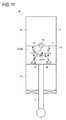
- Fig. 8A shows a configuration in which the pilot stream flowing through the pilot flow path 90 joins the jet stream flowing through the main flow paths 70 and 80 in the same direction along the flow direction of the jet stream.
- Fig. 8B shows a configuration in which a flow changing member 60b is provided, which prevents the collision between the pilot stream and the jet stream to change the flow direction of the pilot stream even when the pilot stream and the jet stream join each other in the opposite direction. Accordingly, the force of at least one flow of the jet stream and the pilot stream is suppressed by the flow changing member 60b. Therefore, the back pressure of the pilot chamber is adjusted.
- the flow changing member 60b shown in Fig. 8B is not limited to the configuration in which the direction of any one flow of the jet stream and the pilot stream is changed and the jet stream and the pilot stream join each other.
- a main object of the shielding member 61 b may be shielding of any one flow of the jet stream and the pilot stream.
- the force of at least one flow of the jet stream and the pilot stream is suppressed by the shielding member 61 b, and the back pressure of the pilot chamber is also adjusted. Therefore, it is possible to adjust the pressurizing force in the valve closing direction acting on the main valve, and it is possible to adjust the damping force to a desired damping force.
- Fig. 8C shows a configuration in which a portion of the main flow path is narrowed so as to form a venturi tube, and the pilot stream flows to a portion which is narrowed at a throttle portion 60c and in which the flow speed increases.
- Fig. 8C is an example when the portion at which the pilot stream joins the jet stream is provided at the intermediate of the jet stream which has a relatively high speed flow generated by the narrowing of the flow path. According to this configuration, the back pressure of the pilot chamber 31 is decreased, and the damping force can be adjusted so as to be decreased.
- Fig. 8D shows a configuration in which the pilot stream flowing through the pilot flow path 90 joins the jet stream flowing through the main flow paths 70 and 80 in the direction opposite to the flow direction of the jet stream and the pilot stream and the jet stream collide with each other.
- Fig. 8E shows a configuration in which the pilot stream and the jet stream collide with each other in a head-to-head relation. According to these configurations, the back pressure of the pilot chamber 31 increases, and thus, it is possible to adjust the damping force so as to be increased.
- the jet stream generated in the flow path 30b narrowed by the main valve 30 may join the flow of the oil which flows out via the pilot flow path 90 from the pilot chamber 31.
- the jet stream which is generated by narrowing the entirety of the main flow paths 70 and 80 or a partial flow path of the main flow paths 70 and 80 other than the location of the flow path 30b at which the main valve 30 is disposed, may join the flow of the oil flowing through the pilot flow path 90 from the pilot chamber 31. In either case, the jet stream joins the flow of the oil which flows out via the pilot flow path 90 from the pilot chamber 31.
- the back pressure of the pilot chamber 31 is also adjusted using the jet stream of the oil passing through the main valve 30 of the main flow paths 70 and 80. Accordingly, the pressurizing force in the valve closing direction acting on the main valve 30 is also adjusted using the jet stream, and thus, it is possible to adjust the damping force to a desired damping force.
- a hydraulic circuit of the shock absorber 1 of the present embodiment will be described.
- the hydraulic circuit is the same in the first embodiment and the second embodiment.
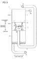
- Fig. 9 is the hydraulic circuit diagram of the shock absorber 1 of the present embodiment.
- the hydraulic circuit shown in Fig. 9 includes the main valve 30, the pilot flow path 90, the compression side inlet check valve 24, the compression side outlet check valve 26, the extension side inlet check valve 25, the extension side outlet check valve 23, and the oil reservoir chamber Re.
- a vehicle body side mounting member 61 is provided on an upper end of the piston rod 8 of a side different from a side on which the piston 21 is provided.
- an axle side mounting member 62 is provided on a lower end of the inner tube 3. That is, the upper end of the piston rod 8 including the vehicle body side mounting member 61 becomes a vehicle body side, and the lower end of the inner tube 3 including the axle side mounting member 62 becomes an axle side.
- the oil reservoir chamber Re is provide to directly communicate with the rod side oil chamber S3.
- the above-mentioned shortage of " ⁇ V 1 - ⁇ V 2 " is supplied from the oil reservoir chamber Re to the rod side oil chamber S3, and the above-mentioned excess of " ⁇ V 3 - ⁇ V 4 " is discharged from the rod side oil chamber S3 to the oil reservoir chamber Re.
- the oil reservoir chamber Re includes an orifice (not shown), a check valve (not shown), or the like, and adjusts a flow rate of the oil.
- the flow of the oil is indicated by a solid line arrow in the hydraulic circuit shown in Fig. 9 .
- the oil inside the piston side oil chamber S2 is compressed by the piston 21, and the pressure in the piston side oil chamber S2 increases. And then, as described above, the oil inside the piston side oil chamber S2 flows into the rod side oil chamber S3 through the main flow path 70 at the time of the compression side stroke. In this case, the compression side damping force is generated in the shock absorber 1 by the flow resistance when the oil passes through the main valve 30.
- the location at which the main flow path 70 and the pilot flow path 90 join each other as shown in Figs. 3 and 6 corresponds to a location at which the reference numerals of the main valve 30 and the pilot flow path 90 are described in the hydraulic circuit shown in Fig. 9 .
- the flow of the oil is indicated by a dashed line arrow in the hydraulic circuit shown in Fig. 9 .
- the oil inside the rod side oil chamber S3 is compressed by the piston 21, and the pressure in the rod side chamber S3 increases. And then, as described above, the oil inside the rod side oil chamber S3 flows into the piston side oil chamber S2 through the main flow path 80 at the time of the extension side stroke.
- the extension side damping force is generated in the shock absorber 1 by the flow resistance when the oil passes through the main valve 30.
- the location at which the main flow path 70 and the pilot flow path 90 join each other as shown in Figs. 3 and 6 corresponds to the location at which the reference numerals of the main valve 30 and the pilot flow path 90 are described in the hydraulic circuit shown in Fig. 9 .
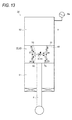
- Figs. 10 to 13 are hydraulic circuit diagrams of other configurations in which the damping force generating apparatus 20 and the solenoid 40 are adopted.
- the same reference numerals are assigned to the same components as the hydraulic circuit shown in Fig. 9 , and the overlapping descriptions are omitted or simplified.
- the flow of the oil at the time of the compression side stroke is indicated by a solid line
- the flow of the oil at the time of the extension side stroke is indicated by a dashed line.
- the hydraulic circuit includes the main valve 30, the pilot flow path 90, the compression side inlet check valve 24, the compression side outlet check valve 26, the extension side inlet check valve 25, the extension side outlet check valve 23, and the oil reservoir chamber Re.
- the damping force generating apparatus 20 and the oil reservoir chamber Re are provided outside the piston 21 and the inner tube 3 in which the piston 21 slides.
- the oil reservoir chamber Re has the function that the oil is supplied and is discharged by an amount corresponding to a volume of the piston rod 8 inserted into and retreated from the inner tube 3.
- the oil reservoir chamber Re may include a bag-shaped bladder in which an inner portion is filled with gas, or the like.
- the oil reservoir chamber Re communicates with an oil path which is branched at a downstream sides of the main valve 30 and the pilot flow path 90. In this way, by branching the oil path which communicates with the oil reservoir chamber Re at the downstream sides of the main valve 30 and the pilot flow path 90, the oil after being dampened by the main valve 30 is introduced into the oil reservoir chamber Re.
- the shock absorber 1 a which suspends the wheel extends and contracts.
- the oil inside the piston side oil chamber S2 is compressed by the piston 21, and the pressure in the piston side oil chamber S2 increases. And then, the oil inside the piston side oil chamber S2 is introduced into the damping force generating apparatus 20.
- the oil introduced into the damping force generating apparatus 20 flows into the rod side oil chamber S1 through the main flow path 70 at the time of the compression side stroke. This time, the compression side damping force is generated in the shock absorber 1 a by the flow resistance when the oil passes through the main valve 30.
- the location at which the main flow path 70 and the pilot flow path 90 join each other as shown in Figs. 3 and 6 corresponds to the location at which the reference numerals of the main valve 30 and the pilot flow path 90 are described in the hydraulic circuit shown in Fig. 10 .
- the oil introduced into the damping force generating apparatus 20 flows into the piston side oil chamber S2 through the main flow path 80 at the time of the extension side stroke. This time, the extension side damping force is generated in the shock absorber 1a by the flow resistance when the oil passes through the main valve 30.
- the location at which the main flow path 70 and the pilot flow path 90 join each other as shown in Figs. 3 and 6 corresponds to a location at which the reference numerals of the main valve 30 and the pilot flow path 90 are described in the hydraulic circuit shown in Fig. 10 .
- the hydraulic circuit includes the main valve 30, the pilot flow path 90, the compression side inlet check valve 24, the compression side outlet check valve 26, the extension side inlet check valve 25, the extension side outlet check valve 23, and the oil reservoir chamber Re.
- the damping force generating apparatus 20 and the oil reservoir chamber Re are provided inside the piston 21 in the inner tube 3.
- the present invention is not limited to this, and the oil reservoir chamber Re may be provided outside the piston 21 in the inner tube 3.
- the oil reservoir chamber Re may be provided in a vicinity of the axle side mounting member (not shown) or the axle side mounting member (not shown) from the flow path which penetrates the inner portion of the piston rod 8.
- the oil reservoir chamber Re communicates with the oil path which is branched at the downstream sides of the main valve 30 and the pilot flow path 90. In this way, by branching the oil path which communicates with the oil reservoir chamber Re at the downstream sides of the main valve 30 and the pilot flow path 90, the oil after being dampened by the main valve 30 is introduced into the oil reservoir chamber Re.
- the oil inside the rod side oil chamber S1 in which the piston rod 8 relatively moves down with respect to the inner tube 3 and the pressure increases, flows into the piston side oil chamber S2 through the main flow path 80 at the time of the extension side stroke.
- the extension side damping force is generated in the shock absorber 1 b by the flow resistance when the oil passes through the main valve 30.
- the location at which the main flow path 70 and the pilot flow path 90 join each other as shown in Figs. 3 and 6 corresponds to a location at which the reference numerals of the main valve 30 and the pilot flow path 90 are described in the hydraulic circuit shown in Fig. 11 .
- the hydraulic circuit includes the main valve 30, the pilot flow path 90, the compression side inlet check valve 24, the compression side outlet check valve 26, the extension side inlet check valve 25, the extension side outlet check valve 23, and the oil reservoir chamber Re.
- the oil reservoir chamber Re is not provided to be juxtaposed with the damping force generating apparatus 20, and is provided to directly communicate with the piston side oil chamber S2.
- the damping force generating apparatus 20 and the oil reservoir chamber Re are provided outside the piston 21 and furthermore outside the inner tube 3.
- an amount of oil corresponding to the volume of the piston rod 8 inserted into the inner tube 3 is introduced into the oil reservoir chamber Re.
- an orifice (not shown), a check valve (not shown), or the like is provided in the inlet of the oil reservoir chamber Re, and thus, the introduction amount of the oil is adjusted.
- the oil inside the piston side oil chamber S2 in which the piston rod 8 relatively moves up with respect to the inner tube 3 and the pressure increases, is introduced to the damping force generating apparatus 20.
- a portion of the oil inside the piston side oil chamber S2 is introduced into the oil reservoir chamber Re.
- the amount of the oil introduced into the oil reservoir chamber Re corresponds to the volume of the piston rod 8 inserted into the inner tube 3. Accordingly, a change of the volume in the inner tube 3 according to the insertion of the piston rod 8 into the inner tube 3 is compensated.
- the flow of the oil in the damping force generating apparatus 20 is the same as the flow described in the compression side stroke (2-1) except for the flow of the oil introduced into the oil reservoir chamber Re.
- the location at which the main flow path 70 and the pilot flow path 90 join each other as shown in Figs. 3 and 6 corresponds to the location at which the reference numerals of the main valve 30 and the pilot flow path 90 are described in the hydraulic circuit shown in Fig. 12 .
- the oil inside the rod side oil chamber S1 in which the piston rod 8 relatively moves down with respect to the inner tube 3 and the pressure increases, is introduced to the damping force generating apparatus 20.
- the oil inside the oil reservoir chamber Re is supplied to the piston side oil chamber S2. Accordingly, the change of the volume in the inner tube 3 according to the retreat of the piston rod 8 from the inner tube 3 is compensated.
- the flow of the oil in the damping force generating apparatus 20 is the same as the flow described in the extension side stroke (2-2) except for the flow of the oil derived from the oil reservoir chamber Re.
- the location at which the main flow path 70 and the pilot flow path 90 join each other as shown in Figs. 3 and 6 corresponds to a location at which the reference numerals of the main valve 30 and the pilot flow path 90 are described in the hydraulic circuit shown in Fig. 12 .
- the hydraulic circuit includes the main valve 30, the pilot flow path 90, the compression side inlet check valve 24, the compression side outlet check valve 26, the extension side inlet check valve 25, the extension side outlet check valve 23, and the oil reservoir chamber Re.
- the function of the hydraulic circuit is provided together in the piston 21. That is, the damping force generating apparatus 20 in which the oil reservoir chamber Re is not juxtaposed is provided inside the piston 21 in the inner tube 3. In this connection, the oil reservoir chamber Re is provided outside the piston 21 and furthermore outside the inner tube 3 in which the piston 21 slides.
- This hydraulic circuit is the same as the hydraulic circuit shown in Fig. 11 except that the oil reservoir chamber Re is not provided inside the piston 21.
- the configuration of the oil reservoir chamber Re is the same as the configuration of the oil reservoir chamber Re shown in Fig. 12 .
- the specific flow of the oil is the same as the flow described in the compression side stroke (3-1) except for the flow of the oil introduced into the oil reservoir chamber Re.
- the location at which the main flow path 70 and the pilot flow path 90 join each other as shown in Figs. 3 and 6 corresponds to a location at which the reference numerals of the main valve 30 and the pilot flow path 90 are described in the hydraulic circuit shown in Fig. 13 .
- a portion of the oil inside the piston side oil chamber S2 is introduced into the oil reservoir chamber Re.
- the amount of the oil introduced into the oil reservoir chamber Re corresponds to the volume of the piston rod 8 inserted into the inner tube 3. Accordingly, the change of the volume in the inner tube 3 according to the insertion of the piston rod 8 into the inner tube 3 is compensated.
- the specific flow of the oil is the same as the flow described in the extension side stroke (3-2) except for the flow of the oil introduced out from the oil reservoir chamber Re.
- the location at which the main flow path 70 and the pilot flow path 90 join each other as shown in Figs. 3 and 6 corresponds to a location at which the reference numerals of the main valve 30 and the pilot flow path 90 are described in the hydraulic circuit shown in Fig. 13 .
- the oil inside the oil reservoir chamber Re is supplied to the piston side oil chamber S2. Accordingly, the change of the volume in the inner tube 3 according to the retreat of the piston rod 8 from the inner tube 3 is compensated.
- shock absorbers 1 a, 1 b, 1c and 1d including the hydraulic circuits having other configurations shown in Figs. 10 to 13 , since the back pressure of the pilot chamber 31 is controlled using the jet stream of the oil passing through the main valve 30 of the main flow path 70, it is possible to obtain the effects similar to those of the shock absorbers 1 shown in the first to third embodiments.
- the damping force generating apparatus 20 and the solenoid 40 are provided inside the piston 21. Accordingly, the damping force generating apparatus 20 and the solenoid 40 are compactly incorporated to the piston 21, and thus, for example, it is possible to use the shock absorbers 1 b and 1 d as the front fork or the rear cushion by which the wheel of the motorcycle is suspended to the vehicle body.
- the damping force generating apparatus 20 and the solenoid 40 are provided outside the piston 21. Accordingly, by disposing the damping force generating apparatus 20 and the solenoid 40 outside the piston 21, it is possible to dispose the damping force generating apparatus 20 and the solenoid 40 at free positions, and it is possible to increase a degree of freedom of a layout. Therefore, it is possible to increase the degree of freedom of the layout with respect to the disposition of the solenoid 40 which is the actuator, and the wiring of a harness or the like.
- the present invention is applied to the inverted shock absorber in which the outer tube is attached to the vehicle body side and the inner tube is attached to the axle side is described.
- the present invention may be also applied to an upright shock absorber in which the inner tube is attached to the vehicle body side and the outer tube is attached to the axle side.
- the present invention is applied to the shock absorber which is used as the front fork by which the front wheel of the motorcycle is suspended to the vehicle body.
- the configuration shown in each hydraulic circuit may be applied to the shock absorber which is used as the rear cushion by which the rear wheel of the motorcycle is suspended to the vehicle body.
- the present invention may be similarly applied to a shock absorber by which wheels of arbitrary vehicles other than the motorcycle are suspended.
Landscapes
- Engineering & Computer Science (AREA)
- General Engineering & Computer Science (AREA)
- Mechanical Engineering (AREA)
- Physics & Mathematics (AREA)
- Fluid Mechanics (AREA)
- Fluid-Damping Devices (AREA)
Abstract
Description
- The present invention relates to a shock absorber which includes a damping force adjusting apparatus which controls a flow of an internal working fluid generated according to extension and contraction motions and adjusts a damping force.
- For example, a shock absorber which is used as a front fork which suspends a front wheel of a motorcycle to a vehicle body, includes a cylinder in which an oil serving as a working fluid is enclosed, a piston which is slidably fitted into the cylinder, a piston rod which is connected to the piston and extends outside the cylinder, and a damping force adjusting apparatus which controls a flow of oil by sliding of the piston in the cylinder and adjusts the damping force.
- In this kind of the hydraulic shock absorber, a damping force adjusting apparatus which largely changes damping force characteristics in a medium-high speed region of a piston speed is known, in which a pilot chamber is formed on a rear portion of a disc valve which selectively opens and closes an oil path provided in the piston, and the pilot chamber communicates with a cylinder chamber in an upstream side of the disc valve via a fixed orifice and communicates with a cylinder chamber in a downstream side of the disc valve via a variable orifice (for example, refer to Patent Literature 1 (JP-UM-A-S62-155242)). According to this kind of the damping force adjusting apparatus, a passage area between two chambers in the cylinder is adjusted by opening and closing the variable orifice, a pressure (back pressure) of the pilot chamber is changed by a pressure loss generated in the variable valve, and thus, it is possible to adjust a valve opening pressure of the disc valve. Accordingly, it is possible to widen an adjustment range of the damping force characteristics.
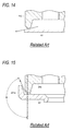
- However, according to the above-mentioned damping force adjusting apparatus, when a flow path area of the variable orifice is decreased so that the damping force is adjusted to a hard side, as shown in
Fig. 14 , an opening degree of adisc valve 101 decreases as the pressure of the pilot chamber increases, and thus, a gap between thedisc valve 101 and avalve seat 102 decreases. Accordingly, a speed of the working fluid passing through the gap is increased, and thus, the working fluid becomes a jet stream. Therefore, a pressure at the gap between thedisc valve 101 and thevalve seat 102 is decreased, a force in a valve closing direction acts on thedisc valve 101, and the damping force is increased. As a result, particularly, there is a problem that an excessive damping force is generated in the medium-high speed region of the piston speed. - Accordingly, as shown in
Fig. 15 , Patent Literature 2 (JP-A-H10-246271 disc valve 201 is bent to avalve seat 202 side and aguide portion 201 a is formed. According to the last mentioned damping force adjusting apparatus, a jet stream of a working fluid passing through a gap between thedisc valve 201 and thevalve seat 202 when the valve is opened is ejected at an ejection angle θ along an outer circumferential portion of thevalve seat 202 toward a gap between thevalve seat 202 and theguide portion 201 a of thedisc valve 201. Accordingly, the force in the valve closing direction which acts on thedisc valve 201 is decreased, and particularly, it is possible to prevent an excessive damping force in the medium-high speed region of the piston speed from being generated. - In the damping force adjusting apparatus which is suggested in
Patent Literature 2 and adopts the configuration shown inFig. 15 , a method is adopted in which the force in the valve closing direction which acts on thedisc valve 201 is decreased by the jet stream which directly acts on thedisc valve 201. - In the damping force adjusting apparatus suggested in
Patent Literature 2, only effects of suppressing the damping force in the medium-high speed region of the piston speed can be expected. On the other hand, it is not possible to generate a greater damping force. Accordingly, there is a problem that an adjustment range of the damping force is relatively narrow. - In view of above, an object of the present invention is to provide a shock absorber capable of obtaining a desired damping force characteristic by widening the adjustment range of the damping force in the medium-high speed region of the piston speed.
- In a first aspect of the present invention, there is provided a shock absorber including: a cylinder in which a working fluid is enclosed; a piston which is slidably fitted in the cylinder; a piston rod which is connected to the piston and extends outside the cylinder; and a damping force generating apparatus which generates a damping force by controlling a flow of the working fluid caused by sliding of the piston in the cylinder, in which the damping force generating apparatus includes: a main flow path through which the working fluid flows by the sliding of the piston in the cylinder; a main valve which generates the damping force by controlling the flow of the working fluid by opening and closing the main flow path; a bypass flow path which is branched from the main flow path or is provided on the main valve; a pilot chamber into which the working fluid flows via the bypass flow path and which applies an internal pressure in a valve closing direction to the main valve by a pressure of the working fluid; and a pilot flow path to which the working fluid flows out from the pilot chamber, wherein a jet stream which is generated in a flow path narrowed by the main valve in the main flow path joins the flow of the working fluid which flows out from the pilot chamber via the pilot flow path.
- In a second aspect of the present invention, there is provided a shock absorber including: a cylinder in which a working fluid is enclosed; a piston which is slidably fitted in the cylinder; a piston rod which is connected to the piston and extends outside the cylinder; and a damping force generating apparatus which generates a damping force by controlling a flow of the working fluid caused by sliding of the piston in the cylinder, in which the damping force generating apparatus includes: a main flow path through which the working fluid flows by the sliding of the piston in the cylinder; a main valve which generates the damping force by controlling the flow of the working fluid by opening and closing the main flow path; a bypass flow path which is branched from the main flow path or is provided on the main valve; a pilot chamber into which the working fluid flows via the bypass flow path and which applies an internal pressure in a valve closing direction to the main valve by a pressure of the working fluid; and a pilot flow path to which the working fluid flows out from the pilot chamber, wherein a jet stream which is generated by narrowing the entire main flow path or a partial flow path of the main flow path other than a location at which the main valve is included, joins the flow of the working fluid which flows out from the pilot chamber via the pilot flow path.
- In a third aspect of the present invention, in addition to the first or second aspect, the flow of the working fluid flowing out from the pilot chamber via the pilot flow path may join the jet stream in a same direction as a flow of the jet stream flowing through the main flow path.
- In a fourth aspect of the present invention, in addition to the first or second aspect, the flow of the working fluid flowing out from the pilot chamber via the pilot flow path may join the jet stream in a direction opposite to a flow of the jet stream flowing through the main flow path.
- In a fifth aspect of the present invention, in addition to any one of the first to fourth aspects, the shock absorber may further include a shielding member which shields at least one of the flow of the working fluid flowing out from the pilot chamber via the pilot flow path and the flow of the jet stream flowing through the main flow path, in which the shielding member is provided in a location at which the flow of the working fluid flowing out from the pilot chamber via the pilot flow path joins the jet stream flowing through the main flow path.
- In a sixth aspect of the present invention, in addition to any one of the first to fourth aspects, the shock absorber may further include a flow changing member which changes a direction of at least one of the flow of the working fluid flowing out from the pilot chamber via the pilot flow path and the flow of the jet stream flowing through the main flow path, in which the flow changing member is provided in a location at which the flow of the working fluid flowing out from the pilot chamber via the pilot flow path joins the jet stream flowing through the main flow path.
- In a seventh aspect of the present invention, in addition to any one of the first to sixth aspects, the damping force generating apparatus may be provided inside the piston.
- In an eighth aspect of the present invention, in addition to any one of the first to sixth aspects, the damping force generating apparatus may be provided outside the piston.
- According to the first aspect, the jet stream which is generated in the flow path narrowed by the main valve in the main flow path joins the flow of the working fluid which flows out from the pilot chamber via the pilot flow path. Alternatively, according to the second aspect, the jet stream which is generated by narrowing the entire main flow path or a partial flow path of the main flow path other than a location at which the main valve is disposed joins the flow of the working fluid which flows out from the pilot chamber via the pilot flow path. The flow of the working fluid which flows out from the pilot chamber via the pilot flow path is adjusted by a force of the jet stream flowing through the main flow path. In either the first aspect or the second aspect, the jet stream joins the flow of the working fluid which flows out from the pilot chamber via the pilot flow path. Accordingly, a back pressure of the pilot chamber is also adjusted using the jet stream of the working fluid which flows through the main valve of the main flow path. Therefore, it is also possible to adjust a pressurizing force in a valve closing direction which acts on the main valve using the jet stream, and thus, it is possible to adjust a desired damping force.
- According to the third aspect, the flow of the working fluid flowing out from the pilot chamber via the pilot flow path joins in the same direction as the jet stream flowing through the main flow path. Accordingly, in a medium-high speed region of a piston speed, a sucking effect is generated in the flow of the working fluid flowing out from the pilot chamber via the pilot flow path, by the force of the jet stream flowing through the main flow path. As a result, the back pressure of the pilot chamber is decreased, the force pressing the main valve in the valve closing direction is decreased, an opening degree of the main valve is increased, and thus, it is possible to prevent the damping force in the medium-high speed region of the piston speed from being increased.
- According to the fourth aspect, the flow of the working fluid which flows out from the pilot chamber via the pilot flow path joins in the direction opposite to the flow of the jet stream flowing through the main flow path. Accordingly, the flow of the working fluid flowing out from the pilot chamber via the pilot flow path collides with the jet stream flowing through the main flow path, and thus, the force of the flow of the working fluid which flows out from the pilot chamber is suppressed. As a result, the back pressure of the pilot chamber is increased, the force pressing the main valve in the valve closing direction is increased, the opening degree of the main valve is decreased, and thus, it is possible to adjust the damping force in the medium-high speed region of the piston speed so as to be increased.
- According to the fifth aspect, the shielding member by which at least one of the flow of the working fluid flowing out from the pilot chamber via the pilot flow path and the jet stream flowing through the main flow path is shielded is provided in the location at which the flow of the working fluid flowing out from the pilot chamber via the pilot flow path joins the jet stream flowing through the main flow path. Accordingly, the force of at least one of the flow of the working fluid which flows out from the pilot chamber via the pilot flow path and the jet stream flowing through the main flow path is suppressed by the shielding member. Accordingly, the back pressure of the pilot chamber is also adjusted. Therefore, it is also possible to adjust the pressurizing force in a valve closing direction which acts on the main valve, and thus, it is possible to adjust a desired damping force.
- According to the sixth aspect, the flow changing member which changes the direction in which at least one of the flow of the working fluid flowing out from the pilot flow path and the jet stream flowing through the main flow path flows is provided in the location at which the flow of the working fluid which flows out from the pilot chamber via the pilot flow path joins the jet stream flowing through the main flow path. Accordingly, the direction in which at least one of the flow of the working fluid flowing out from the pilot flow path and the jet stream flowing through the main flow path working fluid flows is changed at the location at which the flow of the working fluid which flows out from the pilot chamber via the pilot flow path joins the jet stream flowing through the main flow path, and thus, it is possible to adjust a desired damping force by adjusting the back pressure of the pilot chamber.
- According to the seventh aspect, the damping force generating apparatus is compactly incorporated into the piston, and for example, it is possible to use the shock absorber as a front fork or a rear cushion which suspends a wheel of a motorcycle to a vehicle body.
- According to the eighth aspect, by disposing the damping force generating apparatus outside the piston, it is possible to freely dispose the damping force generating apparatus, and thus, it is possible to increase a degree of freedom of the layout. Accordingly, it is also possible to increase the degree of freedom of the layout with respect to disposition of a solenoid serving as an actuator or wiring of a harness or the like.
-
-
Fig. 1 is a vertical cross-sectional diagram of a main portion of a shock absorber according to a first embodiment of the present invention. -
Fig. 2 is a vertical cross-sectional diagram of a damping force generating apparatus of the shock absorber according to the first embodiment of the present invention. -
Fig. 3 is a vertical cross-sectional diagram showing a flow of oil at a time of a compression side stroke in the damping force generating apparatus of the shock absorber according to the first embodiment of the present invention. -
Fig. 4 is a vertical cross-sectional diagram showing a flow of oil at a time of an extension side stroke in the damping force generating apparatus of the shock absorber according to the first embodiment of the present invention. -
Fig. 5 is a graph showing a characteristic of a damping force with respect to a piston speed. -
Fig. 6 is a vertical cross-sectional diagram of a damping force generating apparatus of a shock absorber according to a second embodiment of the present invention. -
Fig. 7 is a partial vertical cross-sectional diagram of a guide portion of a shock absorber according to a third embodiment of the present invention. -
Figs. 8A to 8E are schematic diagrams showing various aspects of joining between a pilot stream and a jet stream. -
Fig. 9 is a hydraulic circuit diagram of the shock absorber of the present embodiment. -
Fig. 10 is a hydraulic circuit diagram having another configuration in the shock absorber in the present embodiment. -
Fig. 11 is a hydraulic circuit diagram having still another configuration in the shock absorber in the present embodiment. -
Fig. 12 is a hydraulic circuit diagram having still another configuration in the shock absorber in the present embodiment. -
Fig. 13 is a hydraulic circuit diagram having still another configuration in the shock absorber in the present embodiment. -
Fig. 14 is a vertical cross-sectional diagram of a main portion of a damping force adjusting apparatus in a hydraulic shock absorber suggested inPatent Literature 1. -
Fig. 15 is a vertical cross-sectional diagram of a main portion of a damping force adjusting apparatus in a hydraulic shock absorber suggested inPatent Literature 2. - Hereinafter, embodiments of the present invention will be described with reference to the accompanying drawings.
-
Fig. 1 is a vertical cross-sectional diagram of a main portion of ashock absorber 1 according to a first embodiment of the present invention, andFig. 2 is a vertical cross-sectional diagram of a damping force generating apparatus of the shock absorber. - The
shock absorber 1 according to the present embodiment is used as an inverted front fork which suspends a front wheel of a motorcycle (not shown) to a vehicle body, and as shown inFig. 1 , in theshock absorber 1, a portion of aninner tube 3 attached to an axle side is inserted into anouter tube 2 attached to the vehicle body side from below. - An upper end portion of the
outer tube 2 is attached to the vehicle body (steering axis) of the motorcycle by an upper bracket (not shown) and a lower bracket (not shown), and an upper end of theouter tube 2 is sealed by a cap bolt 4. Aguide bush 5, anoil seal 6, and a dust seal 7 which comes into sliding-contact with an outer circumference of theinner tube 3 are fitted to an inner circumference of a lower end opening portion of theouter tube 2 to which theinner tube 3 penetrates. - A
hollow piston rod 8 in which an upper end is connected to the cap bolt 4 is hung down in an axial center in theouter tube 2. A portion of thepiston rod 8 penetrates a bottomed cylindrical partition wall member 9 which is fitted to an upper end portion in theinner tube 3, and is inserted into theinner tube 3 from above. In addition, in a lower end portion of thepiston rod 8, asolenoid 40 configuring an actuator of a dampingforce generating apparatus 20, apiston 21, and aspring collar 10 are connected by upper andlower nuts force generating apparatus 20 are incorporated inside thepiston 21. In addition, apower cord 13 for supplying power to thesolenoid 40 is inserted into thepiston rod 8. Arebound spring 14 is wound around thepiston rod 8 on thenut 11. - The lower end portion of the
inner tube 3 is attached to a front axle of the motorcycle via an axle attachment member (not shown), and a portion of the inner tube which is inserted into theouter tube 2 is slidably held vertically with respect to theouter tube 2 by aguide bush 15 which is fitted to an upper end outer circumference of the inserted portion and aguide bush 5 which is fitted to a lower end inner circumference of theouter tube 2. Thus, an annular oil chamber S4, in which an upper end and a lower end are sealed by theguide bush 15 and theguide bush 5, is formed in a gap between the inner circumference of theouter tube 2 and the outer circumference of theinner tube 3. In addition, in theinner tube 3, acommunication hole 3a, through which a rod side oil chamber S3 inside theinner tube 3 and the annular oil chamber S4 communicate with each other, is formed on a portion below the partition wall member 9 described below. - In addition, a
rod guide 16 to which thepiston rod 8 penetrates is fitted into an axial center of a bottom portion of the partition wall member 9 fitted to an inner circumference of an upper end portion of theinner tube 3. Moreover, thepiston rod 8 is slidably held vertically by therod guide 16. Theinner tube 3 is an example of a cylinder. - The
piston 21 is slidably fitted vertically to the inner circumference of theinner tube 3. An inner portion enclosed by theouter tube 2 and theinner tube 3 is partitioned vertically by the partition wall member 9, and an upper space is an oil reservoir chamber Re which functions as a reservoir. The oil reservoir chamber Re is configured of an oil accommodation portion Ro in which the oil is supplied from and is discharged to the rod side oil chamber S3 through the partition wall member 9 as a border, and a gas accommodation portion Rg which is filled with a gas such as air. - In addition, a space below the partition wall member 9 inside the
inner tube 3 is partitioned into the rod side oil chamber S3 and a piston side oil chamber S2 by thepiston 21. The rod side oil chamber S3 and the piston side oil chamber S2 are filled with the oil serving as a working fluid. In addition, asuspension spring 17 is interposed between the bottom portion of theinner tube 3 and thespring collar 10. Moreover, leakage of the oil from theinner tube 3 is prevented by a sealing effect of theoil seal 6. Penetration of dust from the lower end opening portion of theouter tube 2 is prevented by a sealing effect of the dust seal 7. - Next, a configuration of the damping
force generating apparatus 20 will be described below in detail with reference toFig. 2 . - In the damping
force generating apparatus 20, the main portions are incorporated into thepiston 21. Thepiston 21 is divided into two portions such as anupper piston 21 A and alower piston 21B. In addition, avalve stopper 22, an extension sideoutlet check valve 23, alower piston 21 B, a compression sideinlet check valve 24, an extension sideinlet check valve 25, anupper piston 21 A, a compression sideoutlet check valve 26, avalve stopper 27, avalve seat member 28, and asolenoid 40 are assembled in the vertical direction (axial direction) in this order from below, and thus, the dampingforce generating apparatus 20 is configured. - A
rod portion 28A integrally protrudes downward from an axial center of thevalve seat member 28. Therod portion 28A penetrates center portions in the radial directions of thevalve stopper 27, the compression sideoutlet check valve 26, theupper piston 21 A, the extension sideinlet check valve 25, the compression sideinlet check valve 24, thelower piston 21 B, the extension sideoutlet check valve 23, and thevalve stopper 22, and anut 12 is screwed to a lower end portion of therod portion 28A. - A
main valve member 29 which is fitted to an outer circumference of therod portion 28A of thevalve seat member 28 is accommodated in aconcave portion 21 a of thelower piston 21 B. Amain valve 30 having an approximately cylindrical shape is slidably fitted and held vertically to an outer circumference of themain valve member 29. An annular pilot member (back pressure chamber) 31 partitioned by themain valve member 29 is formed on a rear surface side (lower side inFig. 2 ) of themain valve 30 of theconcave portion 21 a of themain valve member 29. Aplate spring 32 which biases themain valve 30 in an up direction (valve closing side) to seat themain valve 30 on a lower surface (seating surface) of theupper piston 21 A is accommodated in thepilot chamber 31. - A
flow path 33 is formed between theconcave portion 21 a of thelower piston 21 B and the outer circumference of themain valve 30. Theflow path 33 communicates with thepilot chamber 31 via anoil hole 30a which is formed in themain valve 30. - A
space 34 which is cut in a taper shape is formed on a lower inner circumference of theupper piston 21 A. Anoil hole 21 b which penetrates theupper piston 21A in the vertical direction and aninclined oil hole 21 c are formed in theupper piston 21 A. Here, theoil hole 21 b is normally opened to the rod side oil chamber S3 (refer toFig. 1 ) in theinner tube 3, and is selectively opened and closed by the extension sideinlet check valve 25. In addition, theoil hole 21 c is normally opened to thespace 34, and is selectively opened and closed by the compression sideoutlet check valve 26. - A
space 35 which is cut in a taper shape is formed on a lower inner circumference of thelower piston 21 B. In addition, anoil hole 21d which penetrates thelower piston 21 B in the vertical direction and aninclined oil hole 21 e are formed in thelower piston 21 B. Here, theoil hole 21 d is normally opened to the piston side oil chamber S2 (refer toFig. 1 ) formed in theinner tube 3, and is selectively opened and closed by the compression sideinlet check valve 24. In addition, theoil hole 21 e is normally opened to thespace 35, and is selectively opened and closed by the extension sideoutlet check valve 23. - A
concave portion 28a which is opened upward is formed on an axial center upper portion of thevalve seat member 28. Anoil hole 28b is formed downward in the axial center of therod portion 28A from theconcave portion 28a. In addition, an oil hole 28c is formed outward in the radial direction from a lower end portion of theoil hole 28b at a light angle. The oil hole 28c communicates with thepilot chamber 31 via an oil hole (not shown) which is formed on themain valve member 29 in the radial direction. - A plurality of
oil holes 29a which penetrate in the axial direction are formed on themain valve member 29. One end (upper end) of theoil hole 29a communicates with theoil hole 21 c of theupper piston 21 A via thespace 34 of theupper piston 21 A, and the other end (lower end) communicates with theoil hole 21 e of thelower piston 21 B via thespace 35 of thelower piston 21 B. - A
gap 37 in the vertical direction is formed between theupper piston 21 A and thelower piston 21 B by anannular distance collar 36 which is fitted to outer circumferences of bothpistons inlet check valve 24 and the extension sideinlet check valve 25 are provided in thegap 37. The compression sideinlet check valve 24 and the extension sideinlet check valve 25 are biased in the direction, in which theoil hole 21d of thelower piston 21 B and theoil hole 21 b of theupper piston 21 A are closed, by aplate spring 38 interposed between thecheck valves - Here, a configuration of the
solenoid 40 will be described. - The
solenoid 40 is configured to accommodate two bottomedcylindrical cores annular coil 44, aplunger 45 accommodated in thecores hollow operating rod 46 which penetrates an axial center of theplunger 45, and so on inside acylindrical casing 41 in which a lower end opening inner circumference is screwed to the outer circumference of thevalve seat member 28. Both end portions in the vertical direction of the operatingrod 46 are supported to be movable in the vertical direction bycylindrical guide bushes 47 and 48. In addition, apilot valve 49 is connected to a lower end outer circumference of the operatingrod 46 facing theconcave portion 28a of thevalve seat member 28. - The
pilot valve 49 is fitted to the inner circumference of theconcave portion 28a of thevalve seat member 28 to be movable in the vertical direction, is selectively seated on a taperedvalve seat 28d formed on an upper end of theoil hole 28b formed in the axial center of thevalve seat member 28, and thus, opens and closes theoil hole 28b. Here, aspace 50 which is partitioned by thepilot valve 49 is formed in theconcave portion 28a of thevalve seat member 28. Moreover, aspring 51 which biases thepilot valve 49 in a valve opening direction (up direction inFig. 2 ) is accommodated in thespace 50. Here, thespace 50 formed in thevalve seat member 28 communicates with thepilot chamber 31 via the oil holes 28b and 28c of thevalve seat member 28 and an oil hole (not shown) formed in themain valve member 29. In addition, anoil hole 49a penetrates thepilot valve 49. Theoil hole 49a is normally opened to thespace 50. - A concave space 52 is formed on an end surface of the
core 42 of thesolenoid 40 between thevalve seat member 28 and thecore 42 of thesolenoid 40. A fail-valve 53 which selectively opens and closes theoil hole 49a of thepilot valve 49 is provided in the space 52. The fail-valve 53 is slidably held vertically on an outer circumference of the operatingrod 46, and is biased in a valve closing direction (down inFig. 2 ) by aspring 54 accommodated in the space 52. In addition, a spring constant of thespring 54 is set to be smaller than a spring constant of aspring 51 which biases thepilot valve 49 in the valve opening direction. - An
oil hole 28e which penetrates in the vertical direction is formed in thevalve seat member 28. The space 52 communicates with thespace 34 of theupper piston 21 A via theoil hole 28e, acylindrical flow path 55 formed between thevalve stopper 27 and thevalve seat member 28, and acylindrical flow path 56 formed between theupper piston 21 A and therod portion 28A of thevalve seat member 28. - In the
shock absorber 1 according to the present embodiment, acylindrical guide portion 29A which extends to thespace 34 of theupper piston 21 A toward above is formed at a center portion in the radial direction of themain valve member 29. A taperedguide surface 29b which is inclined toward above is formed on an inner circumferential surface of theguide portion 29A. - In the damping
force generating apparatus 20 configured as described above, theoil hole 21 d of thelower piston 21 B, thegap 37, thespace 34 of theupper piston 21 A, and theoil hole 21 c of theupper piston 21 A configure amain flow path 70 at a time of a compression side stroke. Themain valve 30, the compression sideinlet check valve 24, and the compression sideoutlet check valve 26 are provided in themain flow path 70. Moreover, theoil hole 21 b of theupper piston 21 A, thegap 37, theoil hole 29a of themain valve member 29, and theoil hole 21 e of thelower piston 21 B configure amain flow path 80 at a time of an extension side stroke. Themain valve 30, the extension sideinlet check valve 25, and the extension sideoutlet check valve 23 are provided in themain flow path 80. - In addition, the
gap 37 between theupper piston 21 A and thelower piston 21 B, theflow path 33 formed on the outer circumferential side of themain valve 30, theoil hole 30a of themain valve 30, thepilot chamber 31, an oil hole (not shown) formed in themain valve member 29,oil holes 28c and 28b formed in thevalve seat member 28, thespace 50 formed by thepilot valve 49 and thevalve seat member 28, theoil hole 49a formed in thepilot valve 49, the space 52 formed in thecore 42 of thesolenoid 40, theoil hole 28e formed in thevalve seat member 28, theflow path 55 formed between thevalve stopper 27 and thevalve seat member 28, theflow path 56 communicating with theflow path 55, and thespace 34 of theupper piston 21A configure apilot flow path 90 for compression and extension side strokes. Thepilot valve 49 and the fail-valve 53 are provided on thepilot flow path 90. Here, theflow path 33 and theoil hole 30a of themain valve 30 also function as a bypass flow path through which a portion of the oil flowing through themain flow paths pilot chamber 31. - Next, operations at the time of the compression side stroke and at the time of the extension side stroke of the
shock absorber 1 configured as above will be described with reference toFigs. 3 to 5 . In this connection,Fig. 3 is a vertical cross-sectional diagram showing a flow of oil at the time of the compression side stroke in the damping force generating apparatus of theshock absorber 1 according to the present embodiment,Fig. 4 is a vertical cross-sectional diagram showing the flow of the oil at the time of the extension side stroke in the damping force generating apparatus, andFig. 5 is a graph showing a characteristic of a damping force with respect to a piston speed. - First, an operation at the time of the compression side stroke of the
shock absorber 1 will be described below based onFig. 3 . - When the front wheel moves up and down by following irregularity of a road surface during travelling of the motorcycle, the
outer tube 2 and theinner tube 3 of theshock absorber 1 which suspends the front wheel extend and contract. In the compression side stroke in which theinner tube 3 relatively moves up with respect to theouter tube 2, the oil in the piston side oil chamber S2 is compressed by thepiston 21, and the pressure in the piston side chamber S2 increases. And then, the oil in the piston side oil chamber S2 flows into the rod side oil chamber S3 through themain flow path 70 at the time of the compression side stroke. Specifically, as shown by a solid line arrow inFig. 3 , the oil passes through theoil hole 21 d of thelower piston 21 B from the piston side oil chamber S2, flows to thegap 37 by pushing to open the compression sideinlet check valve 24 against the biasing force of theplate spring 38, flows to theoil hole 21 c of theupper piston 21 A via thespace 34 from thegap 37 by pushing to open themain valve 30 against the force in the valve closing direction due to theplate spring 32 and the back pressure of thepilot chamber 31 through the pressure in thegap 37, and flows into the rod side oil chamber S3 by pushing to open the compression sideoutlet check valve 26. In this case, a compression side damping force is generated in theshock absorber 1 by a flow resistance generated when the oil passes through themain valve 30. - Meanwhile, a portion of the oil flowing into the
gap 37 through theoil hole 21 d of thelower piston 21 B from the piston side oil chamber S2 joins the oil which flows through themain flow path 70 via thepilot flow path 90. Specifically, as shown by a dashed line arrow inFig. 3 , a portion of the oil flowing into thegap 37 through theoil hole 21 d of thelower piston 21 B from the piston side oil chamber S2 passes through theoil hole 30a of themain valve 30 from theflow path 33 of the outer circumferential side of themain valve 30, flows into thepilot chamber 31, and flows into thespace 50 of thevalve seat member 28 through the oil hole (not shown) of themain valve member 29, theoil holes 28c and 28b of thevalve seat member 28, and a gap between thepilot valve 49 and thevalve seat 28d from thepilot chamber 31. Moreover, the oil flowing into thespace 50 of thevalve seat member 28 flows into the space 52 of the core 42 by pushing to open the fail-valve 53 against a biasing force of thespring 54 through theoil hole 49a of thepilot valve 49, flows into thespace 34 of theupper piston 21 A through theoil hole 28e of thevalve seat member 28 and theflow paths main flow path 70 in thespace 34. - Here, by driving the
solenoid 40, moving the operatingrod 46 and thepilot valve 49 connected to the operating rod in the vertical direction to change an opening degree of thepilot valve 49, it is possible to adjust the back pressure of thepilot chamber 31 by adjusting the flow resistance of the oil passing through thepilot valve 49. Consequently, it is possible to adjust the opening degree of themain valve 30 by controlling a force which presses themain valve 30 in the valve closing direction by the back pressure. In this way, by adjusting the opening degree of themain valve 30, it is possible to adjust the damping force which is generated by the flow resistance of the oil passing through themain valve 30. Specifically, when the opening degree of thepilot valve 49 is narrowed, the back pressure of thepilot chamber 31 increases, the opening degree of themain valve 30 is narrowed, and the damping force increases. Meanwhile, when the opening degree of thepilot valve 49 is largely adjusted, the opening degree of themain valve 30 increases, and the damping force is adjusted to be decreased. - In the first embodiment, as described above, the oil flowing through the
pilot flow path 90 joins the oil flowing through themain flow path 70 in thespace 34 of theupper piston 21 A. However, both oils are controlled by theguide portion 29A of themain valve member 29. Hereinafter, a flow of the oil of thepilot flow path 90 is referred to as a "pilot stream", and a flow of the oil passing through themain valve 30 of the main flow path is referred to as a "jet stream". Here, the jet stream means a phenomenon in which a fluid having a speed flows in substantially one direction into a space from a small hole so as to be ejected, generally. The jet stream includes a case where the oil passing through the flow path is ejected by narrowing the flow path at the location at which the oil passes through themain valve 30 disposed on themain flow paths main valve 30 is disposed such as a portion at which the flow of the oil passing through themain valve 30 disposed on themain flow paths - The oil passing through the
main valve 30 of themain flow path 70 shown inFig. 3 becomes a jet stream which is ejected toward therod portion 28A side (from an outer side to an inner side) in the radial direction. In addition, a flow direction of the pilot stream is controlled by theinclined guide surface 29b of theguide portion 29A. A inclination direction of theguide surface 29b and a direction of the jet stream are the same as each other with theguide portion 29A as a border. Accordingly, in the compression side stroke shown inFig. 3 , the pilot stream guided in the inclination direction of theguide surface 29b joins in the same direction as the direction of the jet stream of the oil passing through themain valve 30 of themain flow path 70. Accordingly, a sucking effect of the pilot stream is generated by a force of the flow in the jet stream of the oil passing through themain valve 30. As a result, the back pressure of thepilot chamber 31 decreases, a force by which themain valve 30 is pressed in the valve closing direction decreases, the opening degree of themain valve 30 increases, and thus, it is possible to prevent the compression side damping force in the medium-high speed region of the piston speed from being increased. Here,Fig. 5 shows the characteristic of the damping force with respect to the piston speed. According to the present embodiment, as shown in a dashed line B relatively with respect to a linear characteristic shown in a solid line A, it is possible to suppress a rate of increase in the compression side damping force of the medium-high speed region of the piston speed. - In the
shock absorber 1 according to the first embodiment shown inFig. 3 , the jet stream which is generated at theflow path 30b narrowed by themain valve 30 joins the pilot stream which is the flow of the oil flowing out through thepilot flow path 90 from thepilot chamber 31. However, the present invention is not limited to this, a jet stream may be generated by narrowing the entiremain flow path 70 or a partial flow path of themain flow path 70 other than a location of theflow path 30b at which themain valve 30 is disposed, and joins the pilot stream. In either case, the jet stream joins the pilot stream. Accordingly, the back pressure of thepilot chamber 31 is also adjusted using the jet stream of the oil passing through themain valve 30 of themain flow path 70. Therefore, it is also possible to adjust a pressurizing force in the valve closing direction which acts on themain valve 30, using the jet stream, and it is possible to adjust the damping force to a desired damping force. - In addition, the
guide portion 29A shown inFig. 3 is not limited to the sucking effect of the jet stream due to the force of the flow in the above-described jet stream according to a shape of theguide portion 29A. For example, by approaching awall surface portion 29d of theguide portion 29A to the jet stream, theguide portion 29A may be a shielding member having an effect which further suppresses the force of the jet stream as the main object. By suppressing the force of the jet stream, the pilot stream and the back pressures of thepilot chamber 31 are also adjusted. Accordingly, it is also possible to adjust the pressurizing force in the valve closing direction which acts on themain valve 30, and it is possible to adjust the damping force to a desired damping force. In this case, thewall surface portion 29d shields the jet stream which is the flow of the oil flowing through themain valve 30 in themain flow path 70. However, the present invention is not limited to this, a shielding member which suppresses the force of the pilot stream flowing out from thepilot chamber 31 via thepilot flow path 90 may be provided, and thus, the damping force may be adjusted to the desired damping force. In addition, the shielding member may be provided not only on either the jet stream side or the pilot stream side as described above but also on both the jet stream side and the pilot stream side, and thus, the damping force may be adjusted to the desired damping force. - In addition, for example, by changing an inclination angle of the
guide surface 29b, theguide portion 29A shown inFig. 3 may be a flow changing member which changes the flow direction of the pilot stream which is the flow of the oil flowing out from thepilot chamber 31 via thepilot flow path 90. By changing the flow direction of the pilot stream, it is possible to adjust the damping force to the desired damping force by adjusting the back pressure of thepilot chamber 31. In this case, theguide portion 29A changes the flow direction of the pilot stream. However, the present invention is not limited to this, a flow changing member which changes the flow direction of the jet stream which is the flow of the oil flowing through themain valve 30 in themain flow path 70 may be provided, and thus, the damping force may be adjusted to the a desired damping force. In addition, the flow changing member may be provided not only on either the jet stream side or the pilot stream side as described above but also on both the jet stream side and the pilot stream side, and thus, the damping force may be adjusted to a desired damping force. Moreover, the shielding member and/or the flow changing member may be provided on the join location between the pilot stream and the jet stream or each outlet of the pilot stream and the jet stream, and the damping force may be adjusted to the desired damping force by adjusting the back pressure of thepilot chamber 31. - In the compression side stroke, the oil corresponding to an amount of an inserted volume of the
piston rod 8 which is inserted into theinner tube 3 is transferred to the annular oil chamber S4 via thecommunication hole 3a from the rod side oil chamber S3 in theinner tube 3. In this case, since an increased amount of volume ΔV1 (supply amount) of the annular oil chamber S4 is larger than an increased amount of volume ΔV2 of thepiston rod 8, in the supply amount of the oil supplied to the annular oil chamber S4, a shortage of "ΔV1 - ΔV2" is supplied from the oil accommodation portion Ro to the rod side oil chamber S3. In addition, the supply of the oil with respect to the shortage is performed by a supply-discharge portion (not shown) which is formed on a bottom portion of the partition wall member 9 and through which the oil is supplied from the rod side oil chamber S3 to the oil accommodation portion Ro and is discharged from the oil accommodation portion Ro to the rod side oil chamber S3. - Next, an operation at the time of the extension side stroke of the
shock absorber 1 will be described below based onFig. 4 . - In the extension side stroke in which the
inner tube 3 relatively moves down with respect to theouter tube 2, the oil in the rod side oil chamber S3 is compressed by thepiston 21, and the pressure in the rod side oil chamber S3 increases. And then, the oil in the rod side oil chamber S3 flows into the piston side oil chamber S2 through themain flow path 80 at the time of the extension side stroke. Specifically, as shown by a solid line arrow inFig. 4 , the oil passes through theoil hole 21 b of theupper piston 21A from the rod side oil chamber S3, flow to thegap 37 by pushing to open the extension sideinlet check valve 25 against the biasing force of theplate spring 38, flows to theoil hole 29a of themain valve member 29 and theoil hole 21 e of thelower piston 21 B from thegap 37 by pushing to open themain valve 30 against the force in the valve closing direction due to theplate spring 32 and the back pressure of thepilot chamber 31 through the pressure in the gap, and flows into the piston side oil chamber S2 by pushing to open the extension sideoutlet check valve 23. In this case, an extension side damping force is generated in theshock absorber 1 by the flow resistance generated when the oil passes through themain valve 30. - Meanwhile, similar to the time of the compression side stroke, a portion of the oil flowing into the
gap 37 through theoil hole 21 b of theupper piston 21 A from the rod side oil chamber S3 joins the oil which flows through themain flow path 80 via thepilot flow path 90. Here, the flow of the oil in thepilot flow path 90 is indicated by a dashed line arrow inFig. 4 . - In the first embodiment, as described above, the oil flowing through the
pilot flow path 90 joins the jet stream of the oil flowing through themain valve 30 of themain flow path 80 in thespace 34 of theupper piston 21 A. - The oil passing through the
main valve 30 of themain flow path 80 shown inFig. 4 becomes the jet stream which is ejected toward therod portion 28A side (from the outer side to the inner side) in the radial direction. In addition, the flow direction of the pilot stream is controlled by theinclined guide surface 29b of theguide portion 29A. However, with theguide portion 29A as a border, the direction of the jet stream becomes different from the inclination direction of theguide surface 29b of theguide portion 29A unlike the direction at the time of the compression side stroke. Accordingly, compared to the compression side stroke, in the extension side stroke, the influence of the sucking effect of the pilot stream by the jet stream is decreased. Therefore, the influence of the effect of suppressing the increase in the damping force in the medium-high speed region of the piston speed is also decreased. - Moreover, in the compression side stroke, the case where the jet stream generated in the
flow path 30b narrowed by themain valve 30 joins the pilot stream, or the case where the jet stream, which is generated by narrowing the entiremain flow path 70 or a partial flow path of themain flow path 70 other than the location of theflow path 30b at which themain valve 30 is disposed, joins the pilot stream is shown. Similarly, also in the extension side stroke, the case where the jet stream generated in theflow path 30b narrowed by themain valve 30 joins the pilot stream, or the case where the jet stream, which is generated by narrowing the entiremain flow path 80 or a partial flow path of themain flow path 80 other than the location of theflow path 30b at which themain valve 30 is disposed, joins the pilot stream may be adopted. In either case, the pressurizing force in the valve closing direction acting on themain valve 30 is adjusted by having the jet stream join the pilot stream, and thus, the damping force may be adjusted to the desired damping force. - In addition, for example, in the compression side stroke, the case where the shielding member and/or the flow changing member is provided on the join location between the pilot stream and the jet stream or each outlet of the pilot stream and the jet stream by changing the shape of the
guide portion 29A is also illustrated. Similarly, also in the extension side stroke, the shielding member and/or the flow changing member may be provided on the join location between the pilot stream and the jet stream or each outlet of the pilot stream and the jet stream, consequently, the back pressure of thepilot chamber 31 is adjusted, and thus, the damping force may be adjusted to the desired damping force. - In the extension side stroke, the oil corresponding to the amount of the retreated volume of the
piston rod 8 which retreats from theinner tube 3 is transferred to the rod side oil chamber S3 via thecommunication hole 3a from the annular oil chamber S4. In this case, since a decreased amount of volume ΔV3 (discharge amount) of the annular oil chamber S4 is larger than a decreased amount of volume ΔV4 of thepiston rod 8, in the discharge amount of the oil discharged to the annular oil chamber S4, an excess of "ΔV3 - ΔV4" is discharged to the oil accommodation portion Ro from the rod side oil chamber S3. In addition, the discharge of the oil with respect to the excess is performed by the supply-discharge portion (not shown) which is formed on the bottom portion of the partition wall member 9 and through which the oil is supplied from the rod side oil chamber S3 to the oil accommodation portion Ro and is discharged from the oil accommodation portion Ro to the rod side oil chamber S3. - In the first embodiment, it is possible to control the back pressure of the
pilot chamber 31 using the join direction between the jet stream of the oil passing through themain valve 30 of themain flow paths pilot chamber 31, the opening degree of themain valve 30 is effectively adjusted, and thus, it is possible to easily adjust the damping force to the desired damping force. - Next, a second embodiment of the present invention will be described below with reference to
Fig. 6 . -
Fig. 6 is a vertical cross-sectional diagram of a damping force generating apparatus 20' of a shock absorber according to the second embodiment of the present invention. InFig. 6 , the same reference numerals are assigned to the same components shown inFig. 2 , and the overlapping descriptions are omitted or simplified. - The basic configurations of the
shock absorber 1 and the damping force generating apparatus 20' according to the second embodiment are the same as those of the first embodiment. However, the damping force generating apparatus 20' according to the second embodiment is different from the first embodiment in that an upper surface of aguide portion 29A' of themain valve member 29 does not protrude to thespace 34 of theupper piston 21 A, and the upper surface is configured of a flat surface. - In the damping force generating apparatus 20' according to the second embodiment, in the compression side stroke, the pilot stream flowing through the
pilot flow path 90 joins the jet stream of the oil passing through themain valve 30 of themain flow paths space 34 of theupper piston 21 A. However, unlike theguide portion 29A, since the upper surface of theguide portion 29A' does not guide the direction of the pilot stream, the sucking effect due to the pilot stream joining the jet stream in the same direction as the jet stream and a collision effect due to the pilot stream joining the jet stream in the direction opposite to the jet stream are suppressed. As a result, the influence on the back pressure of thepilot chamber 31 with respect to the increase of thepilot flow path 90 due to the jet stream and the influence thereon with respect to the decrease of the pilot flow path due to the jet stream are decreased. Accordingly, the force which presses themain valve 30 in the valve closing direction is not relatively increased or decreased, and the opening degree of themain valve 30 can cause the damping force in the medium-high speed region of the piston speed to be a damping force shown in a substantially linear solid line A which is an intermediate line which is not the dashed line B or a one dot chain line C ofFig. 5 . - In the second embodiment, the direction in which the jet stream of the oil passing through the
main valve 30 of themain flow paths pilot chamber 31. Moreover, by controlling the back pressure of thepilot chamber 31, the opening degree of themain valve 30 is effectively adjusted, and thus, it is possible to easily adjust the damping force to the desired damping force. - Next, a third embodiment of the present invention will be described below with reference to
Fig. 7 . -
Fig. 7 is a partial vertical cross-sectional diagram of a guide portion of a shock absorber according to the third embodiment of the present invention. The same reference numerals are assigned to the same components, and the overlapping descriptions are omitted or simplified. - Similar to the first embodiment, even when a
guide portion 29A" shown inFig. 7 protrudes to thespace 34 of theupper piston 21 A, an outer circumference of an upper end portion of theguide portion 29A" can become atapered guide surface 29c which is inclined toward above in the direction opposite to the direction of the first embodiment. Accordingly, the inclination direction of theguide surface 29c shown inFig. 7 and the direction of the jet stream become directions opposite to each other with theguide portion 29A" as the border. Accordingly, in the compression side stroke, the pilot stream guided in the inclination direction of theguide surface 29c joins the jet stream of the oil passing through themain valve 30 of themain flow path 70 in the direction opposite to the direction of the jet stream, and collides with the jet stream. Accordingly, the force of the flow of the pilot stream which flows out via thepilot flow path 90 from thepilot chamber 31 is suppressed due to a collision with the jet stream flowing through themain valve 30. As a result, the back pressure of thepilot chamber 31 increases, the force which presses themain valve 30 in the valve closing direction also increases, and the opening degree of themain valve 30 decreases. Accordingly, it is possible to highly adjust the damping force in the medium-high speed region of the piston speed as shown by the one dot chain line C ofFig. 5 . Similar to the compression side stroke, also in the extension side stroke, since the jet stream and the pilot stream collide with each other in the direction opposite to each other, it is possible to highly adjust the damping force in the medium-high speed region of the piston speed. - In the third embodiment, it is possible to control the back pressure of the
pilot chamber 31 using the join direction between the jet stream of the oil passing through themain valve 30 of themain flow paths pilot chamber 31, the opening degree of themain valve 30 is effectively adjusted, and thus, it is possible to easily adjust the damping force to the desired damping force. - In the first to third embodiments, the jet stream which is generated in the
flow path 30b narrowed by themain valve 30 in themain flow paths pilot flow path 90 from thepilot chamber 31. Accordingly, the back pressure of thepilot chamber 31 is also adjusted using the jet stream of the oil passing through themain valve 30 of themain flow paths main valve 30 using the jet stream, and thus, it is possible to adjust the damping force to a desired damping force. - In addition, as shown in the first to third embodiments, by changing the join direction between the oil flowing through the
pilot flow path 90 and the oil passing through themain valve 30, the back pressure of thepilot chamber 31 is adjusted in only one stroke or both strokes of the compression side stroke and the extension side stroke, and thus, it is possible to adjust the damping force. - Moreover, as shown in the first to third embodiments, the damping
force generating apparatus 20 and thesolenoid 40 are compactly incorporated to thepiston 21, and thus, for example, it is possible to use theshock absorber 1 not only as the front fork by which the front wheel of the motorcycle is suspended to the vehicle body but also as a rear cushion. - In the first to third embodiments, the back pressure of the
pilot chamber 31 is controlled by controlling the flow of the oil flowing to the downstream of thepilot valve 49 of thepilot flow path 90 and the flow of the jet stream of the oil passing through themain valve 30 of themain flow paths pilot chamber 31, aspects schematically shown inFigs. 8A to 8C are considered. Meanwhile, for example, as a configuration for increasing the back pressure of thepilot chamber 31, aspects schematically shown inFigs. 8D and 8E are considered. - That is,
Fig. 8A shows a configuration in which the pilot stream flowing through thepilot flow path 90 joins the jet stream flowing through themain flow paths Fig. 8B shows a configuration in which aflow changing member 60b is provided, which prevents the collision between the pilot stream and the jet stream to change the flow direction of the pilot stream even when the pilot stream and the jet stream join each other in the opposite direction. Accordingly, the force of at least one flow of the jet stream and the pilot stream is suppressed by theflow changing member 60b. Therefore, the back pressure of the pilot chamber is adjusted. Accordingly, it is possible to adjust the pressurizing force in the valve closing direction acting on the main valve, and it is possible to adjust the damping force to a desired damping force. However, theflow changing member 60b shown inFig. 8B is not limited to the configuration in which the direction of any one flow of the jet stream and the pilot stream is changed and the jet stream and the pilot stream join each other. For example, by extending the length of the shieldingmember 61 b which is the location at which the pilot stream collides with theflow changing member 60b, or the like, a main object of the shieldingmember 61 b may be shielding of any one flow of the jet stream and the pilot stream. Accordingly, the force of at least one flow of the jet stream and the pilot stream is suppressed by the shieldingmember 61 b, and the back pressure of the pilot chamber is also adjusted. Therefore, it is possible to adjust the pressurizing force in the valve closing direction acting on the main valve, and it is possible to adjust the damping force to a desired damping force. -
Fig. 8C shows a configuration in which a portion of the main flow path is narrowed so as to form a venturi tube, and the pilot stream flows to a portion which is narrowed at athrottle portion 60c and in which the flow speed increases.Fig. 8C is an example when the portion at which the pilot stream joins the jet stream is provided at the intermediate of the jet stream which has a relatively high speed flow generated by the narrowing of the flow path. According to this configuration, the back pressure of thepilot chamber 31 is decreased, and the damping force can be adjusted so as to be decreased. - Meanwhile,
Fig. 8D shows a configuration in which the pilot stream flowing through thepilot flow path 90 joins the jet stream flowing through themain flow paths Fig. 8E shows a configuration in which the pilot stream and the jet stream collide with each other in a head-to-head relation. According to these configurations, the back pressure of thepilot chamber 31 increases, and thus, it is possible to adjust the damping force so as to be increased. - In this connection, in each configuration shown in
Figs. 8A to 8D , as described in the first to third embodiments, the jet stream generated in theflow path 30b narrowed by themain valve 30 may join the flow of the oil which flows out via thepilot flow path 90 from thepilot chamber 31. In addition, the present invention is not limited to this, the jet stream, which is generated by narrowing the entirety of themain flow paths main flow paths flow path 30b at which themain valve 30 is disposed, may join the flow of the oil flowing through thepilot flow path 90 from thepilot chamber 31. In either case, the jet stream joins the flow of the oil which flows out via thepilot flow path 90 from thepilot chamber 31. Accordingly, the back pressure of thepilot chamber 31 is also adjusted using the jet stream of the oil passing through themain valve 30 of themain flow paths main valve 30 is also adjusted using the jet stream, and thus, it is possible to adjust the damping force to a desired damping force. - A hydraulic circuit of the
shock absorber 1 of the present embodiment will be described. In this connection, the hydraulic circuit is the same in the first embodiment and the second embodiment. -
Fig. 9 is the hydraulic circuit diagram of theshock absorber 1 of the present embodiment. The hydraulic circuit shown inFig. 9 includes themain valve 30, thepilot flow path 90, the compression sideinlet check valve 24, the compression sideoutlet check valve 26, the extension sideinlet check valve 25, the extension sideoutlet check valve 23, and the oil reservoir chamber Re. In addition, as shown inFig. 9 , for example, a vehicle bodyside mounting member 61 is provided on an upper end of thepiston rod 8 of a side different from a side on which thepiston 21 is provided. Meanwhile, for example, an axleside mounting member 62 is provided on a lower end of theinner tube 3. That is, the upper end of thepiston rod 8 including the vehicle bodyside mounting member 61 becomes a vehicle body side, and the lower end of theinner tube 3 including the axleside mounting member 62 becomes an axle side. - In addition, in the hydraulic circuit shown in
Fig. 9 , the oil reservoir chamber Re is provide to directly communicate with the rod side oil chamber S3. The above-mentioned shortage of "ΔV1 - ΔV2" is supplied from the oil reservoir chamber Re to the rod side oil chamber S3, and the above-mentioned excess of "ΔV3 - ΔV4" is discharged from the rod side oil chamber S3 to the oil reservoir chamber Re. In this connection, the oil reservoir chamber Re includes an orifice (not shown), a check valve (not shown), or the like, and adjusts a flow rate of the oil. - In the
shock absorber 1 including such hydraulic circuit, in the compression side stroke, the flow of the oil is indicated by a solid line arrow in the hydraulic circuit shown inFig. 9 . In the compression side stroke in which theinner tube 3 relatively moves up with respect to theouter tube 2, the oil inside the piston side oil chamber S2 is compressed by thepiston 21, and the pressure in the piston side oil chamber S2 increases. And then, as described above, the oil inside the piston side oil chamber S2 flows into the rod side oil chamber S3 through themain flow path 70 at the time of the compression side stroke. In this case, the compression side damping force is generated in theshock absorber 1 by the flow resistance when the oil passes through themain valve 30. Here, the location at which themain flow path 70 and thepilot flow path 90 join each other as shown inFigs. 3 and6 corresponds to a location at which the reference numerals of themain valve 30 and thepilot flow path 90 are described in the hydraulic circuit shown inFig. 9 . - In the extension side stroke, the flow of the oil is indicated by a dashed line arrow in the hydraulic circuit shown in
Fig. 9 . In the extension side stroke in which theinner tube 3 relatively moves down with respect to theouter tube 2, the oil inside the rod side oil chamber S3 is compressed by thepiston 21, and the pressure in the rod side chamber S3 increases. And then, as described above, the oil inside the rod side oil chamber S3 flows into the piston side oil chamber S2 through themain flow path 80 at the time of the extension side stroke. In this case, the extension side damping force is generated in theshock absorber 1 by the flow resistance when the oil passes through themain valve 30. Here, the location at which themain flow path 70 and thepilot flow path 90 join each other as shown inFigs. 3 and6 corresponds to the location at which the reference numerals of themain valve 30 and thepilot flow path 90 are described in the hydraulic circuit shown inFig. 9 . -
Figs. 10 to 13 are hydraulic circuit diagrams of other configurations in which the dampingforce generating apparatus 20 and thesolenoid 40 are adopted. In addition, the same reference numerals are assigned to the same components as the hydraulic circuit shown inFig. 9 , and the overlapping descriptions are omitted or simplified. InFigs. 10 to 13 , the flow of the oil at the time of the compression side stroke is indicated by a solid line, and the flow of the oil at the time of the extension side stroke is indicated by a dashed line. - As shown in
Fig. 10 , the hydraulic circuit includes themain valve 30, thepilot flow path 90, the compression sideinlet check valve 24, the compression sideoutlet check valve 26, the extension sideinlet check valve 25, the extension sideoutlet check valve 23, and the oil reservoir chamber Re. - In addition, in this hydraulic circuit, the damping
force generating apparatus 20 and the oil reservoir chamber Re are provided outside thepiston 21 and theinner tube 3 in which thepiston 21 slides. The oil reservoir chamber Re has the function that the oil is supplied and is discharged by an amount corresponding to a volume of thepiston rod 8 inserted into and retreated from theinner tube 3. For example, the oil reservoir chamber Re may include a bag-shaped bladder in which an inner portion is filled with gas, or the like. - The oil reservoir chamber Re communicates with an oil path which is branched at a downstream sides of the
main valve 30 and thepilot flow path 90. In this way, by branching the oil path which communicates with the oil reservoir chamber Re at the downstream sides of themain valve 30 and thepilot flow path 90, the oil after being dampened by themain valve 30 is introduced into the oil reservoir chamber Re. - When a wheel moves up and down by following irregularity of a road surface during traveling of the motorcycle, the
shock absorber 1 a which suspends the wheel extends and contracts. In the compression side stroke in which thepiston rod 8 relatively moves up with respect to theinner tube 3, the oil inside the piston side oil chamber S2 is compressed by thepiston 21, and the pressure in the piston side oil chamber S2 increases. And then, the oil inside the piston side oil chamber S2 is introduced into the dampingforce generating apparatus 20. - The oil introduced into the damping
force generating apparatus 20 flows into the rod side oil chamber S1 through themain flow path 70 at the time of the compression side stroke. This time, the compression side damping force is generated in theshock absorber 1 a by the flow resistance when the oil passes through themain valve 30. Here, the location at which themain flow path 70 and thepilot flow path 90 join each other as shown inFigs. 3 and6 corresponds to the location at which the reference numerals of themain valve 30 and thepilot flow path 90 are described in the hydraulic circuit shown inFig. 10 . - In the extension side stroke in which the
piston rod 8 relatively moves down with respect to theinner tube 3, thepiston 21 moves down in theinner tube 3 along with thepiston rod 8. Accordingly, the oil inside the rod side oil chamber S1 is compressed by thepiston 21, and the pressure in the rod side oil chamber S1 increases. And then, the oil inside the rod side oil chamber S1 is introduced into the dampingforce generating apparatus 20. - The oil introduced into the damping
force generating apparatus 20 flows into the piston side oil chamber S2 through themain flow path 80 at the time of the extension side stroke. This time, the extension side damping force is generated in theshock absorber 1a by the flow resistance when the oil passes through themain valve 30. Here, the location at which themain flow path 70 and thepilot flow path 90 join each other as shown inFigs. 3 and6 corresponds to a location at which the reference numerals of themain valve 30 and thepilot flow path 90 are described in the hydraulic circuit shown inFig. 10 . - As shown in
Fig. 11 , the hydraulic circuit includes themain valve 30, thepilot flow path 90, the compression sideinlet check valve 24, the compression sideoutlet check valve 26, the extension sideinlet check valve 25, the extension sideoutlet check valve 23, and the oil reservoir chamber Re. - In this hydraulic circuit, the damping
force generating apparatus 20 and the oil reservoir chamber Re are provided inside thepiston 21 in theinner tube 3. In addition, the present invention is not limited to this, and the oil reservoir chamber Re may be provided outside thepiston 21 in theinner tube 3. Moreover, the oil reservoir chamber Re may be provided in a vicinity of the axle side mounting member (not shown) or the axle side mounting member (not shown) from the flow path which penetrates the inner portion of thepiston rod 8. - The oil reservoir chamber Re communicates with the oil path which is branched at the downstream sides of the
main valve 30 and thepilot flow path 90. In this way, by branching the oil path which communicates with the oil reservoir chamber Re at the downstream sides of themain valve 30 and thepilot flow path 90, the oil after being dampened by themain valve 30 is introduced into the oil reservoir chamber Re. - The oil inside the piston side oil chamber S2, in which the
piston rod 8 relatively moves up with respect to theinner tube 3 and the pressure increases, flows into the rod side oil chamber S1 through themain flow path 70 at the time of the compression side stroke. This time, the compression side damping force is generated in theshock absorber 1 b by the flow resistance when the oil passes through themain valve 30. Here, the location at which themain flow path 70 and thepilot flow path 90 join each other as shown inFigs. 3 and6 corresponds to the location at which the reference numerals of themain valve 30 and thepilot flow path 90 are described in the hydraulic circuit shown inFig. 11 . - The oil inside the rod side oil chamber S1, in which the
piston rod 8 relatively moves down with respect to theinner tube 3 and the pressure increases, flows into the piston side oil chamber S2 through themain flow path 80 at the time of the extension side stroke. This time, the extension side damping force is generated in theshock absorber 1 b by the flow resistance when the oil passes through themain valve 30. Here, the location at which themain flow path 70 and thepilot flow path 90 join each other as shown inFigs. 3 and6 corresponds to a location at which the reference numerals of themain valve 30 and thepilot flow path 90 are described in the hydraulic circuit shown inFig. 11 . - As shown in
Fig. 12 , the hydraulic circuit includes themain valve 30, thepilot flow path 90, the compression sideinlet check valve 24, the compression sideoutlet check valve 26, the extension sideinlet check valve 25, the extension sideoutlet check valve 23, and the oil reservoir chamber Re. - As shown in
Fig. 12 , the oil reservoir chamber Re is not provided to be juxtaposed with the dampingforce generating apparatus 20, and is provided to directly communicate with the piston side oil chamber S2. In addition, in this case, the dampingforce generating apparatus 20 and the oil reservoir chamber Re are provided outside thepiston 21 and furthermore outside theinner tube 3. In addition, an amount of oil corresponding to the volume of thepiston rod 8 inserted into theinner tube 3 is introduced into the oil reservoir chamber Re. In this connection, an orifice (not shown), a check valve (not shown), or the like is provided in the inlet of the oil reservoir chamber Re, and thus, the introduction amount of the oil is adjusted. - The oil inside the piston side oil chamber S2, in which the
piston rod 8 relatively moves up with respect to theinner tube 3 and the pressure increases, is introduced to the dampingforce generating apparatus 20. In addition, a portion of the oil inside the piston side oil chamber S2 is introduced into the oil reservoir chamber Re. The amount of the oil introduced into the oil reservoir chamber Re corresponds to the volume of thepiston rod 8 inserted into theinner tube 3. Accordingly, a change of the volume in theinner tube 3 according to the insertion of thepiston rod 8 into theinner tube 3 is compensated. - The flow of the oil in the damping
force generating apparatus 20 is the same as the flow described in the compression side stroke (2-1) except for the flow of the oil introduced into the oil reservoir chamber Re. Here, the location at which themain flow path 70 and thepilot flow path 90 join each other as shown inFigs. 3 and6 corresponds to the location at which the reference numerals of themain valve 30 and thepilot flow path 90 are described in the hydraulic circuit shown inFig. 12 . - The oil inside the rod side oil chamber S1, in which the
piston rod 8 relatively moves down with respect to theinner tube 3 and the pressure increases, is introduced to the dampingforce generating apparatus 20. In addition, the oil inside the oil reservoir chamber Re is supplied to the piston side oil chamber S2. Accordingly, the change of the volume in theinner tube 3 according to the retreat of thepiston rod 8 from theinner tube 3 is compensated. - The flow of the oil in the damping
force generating apparatus 20 is the same as the flow described in the extension side stroke (2-2) except for the flow of the oil derived from the oil reservoir chamber Re. Here, the location at which themain flow path 70 and thepilot flow path 90 join each other as shown inFigs. 3 and6 corresponds to a location at which the reference numerals of themain valve 30 and thepilot flow path 90 are described in the hydraulic circuit shown inFig. 12 . - As shown in
Fig. 13 , the hydraulic circuit includes themain valve 30, thepilot flow path 90, the compression sideinlet check valve 24, the compression sideoutlet check valve 26, the extension sideinlet check valve 25, the extension sideoutlet check valve 23, and the oil reservoir chamber Re. - In the hydraulic circuit of this embodiment, the function of the hydraulic circuit is provided together in the
piston 21. That is, the dampingforce generating apparatus 20 in which the oil reservoir chamber Re is not juxtaposed is provided inside thepiston 21 in theinner tube 3. In this connection, the oil reservoir chamber Re is provided outside thepiston 21 and furthermore outside theinner tube 3 in which thepiston 21 slides. - This hydraulic circuit is the same as the hydraulic circuit shown in
Fig. 11 except that the oil reservoir chamber Re is not provided inside thepiston 21. In addition, the configuration of the oil reservoir chamber Re is the same as the configuration of the oil reservoir chamber Re shown inFig. 12 . - The specific flow of the oil is the same as the flow described in the compression side stroke (3-1) except for the flow of the oil introduced into the oil reservoir chamber Re. Here, the location at which the
main flow path 70 and thepilot flow path 90 join each other as shown inFigs. 3 and6 corresponds to a location at which the reference numerals of themain valve 30 and thepilot flow path 90 are described in the hydraulic circuit shown inFig. 13 . - In addition, a portion of the oil inside the piston side oil chamber S2 is introduced into the oil reservoir chamber Re. The amount of the oil introduced into the oil reservoir chamber Re corresponds to the volume of the
piston rod 8 inserted into theinner tube 3. Accordingly, the change of the volume in theinner tube 3 according to the insertion of thepiston rod 8 into theinner tube 3 is compensated. - The specific flow of the oil is the same as the flow described in the extension side stroke (3-2) except for the flow of the oil introduced out from the oil reservoir chamber Re. Here, the location at which the
main flow path 70 and thepilot flow path 90 join each other as shown inFigs. 3 and6 corresponds to a location at which the reference numerals of themain valve 30 and thepilot flow path 90 are described in the hydraulic circuit shown inFig. 13 . - In addition, the oil inside the oil reservoir chamber Re is supplied to the piston side oil chamber S2. Accordingly, the change of the volume in the
inner tube 3 according to the retreat of thepiston rod 8 from theinner tube 3 is compensated. - Also in the
shock absorbers Figs. 10 to 13 , since the back pressure of thepilot chamber 31 is controlled using the jet stream of the oil passing through themain valve 30 of themain flow path 70, it is possible to obtain the effects similar to those of theshock absorbers 1 shown in the first to third embodiments. - Moreover, in the
shock absorbers Figs. 11 and13 , the dampingforce generating apparatus 20 and thesolenoid 40 are provided inside thepiston 21. Accordingly, the dampingforce generating apparatus 20 and thesolenoid 40 are compactly incorporated to thepiston 21, and thus, for example, it is possible to use theshock absorbers - In addition, in the
shock absorbers Figs. 10 and12 , the dampingforce generating apparatus 20 and thesolenoid 40 are provided outside thepiston 21. Accordingly, by disposing the dampingforce generating apparatus 20 and thesolenoid 40 outside thepiston 21, it is possible to dispose the dampingforce generating apparatus 20 and thesolenoid 40 at free positions, and it is possible to increase a degree of freedom of a layout. Therefore, it is possible to increase the degree of freedom of the layout with respect to the disposition of thesolenoid 40 which is the actuator, and the wiring of a harness or the like. - In addition, hereinbefore, the case where the present invention is applied to the inverted shock absorber in which the outer tube is attached to the vehicle body side and the inner tube is attached to the axle side is described. However, the present invention may be also applied to an upright shock absorber in which the inner tube is attached to the vehicle body side and the outer tube is attached to the axle side.
- In addition, hereinbefore, the case where the present invention is applied to the shock absorber which is used as the front fork by which the front wheel of the motorcycle is suspended to the vehicle body is described. However, for example, the configuration shown in each hydraulic circuit may be applied to the shock absorber which is used as the rear cushion by which the rear wheel of the motorcycle is suspended to the vehicle body. In addition, the present invention may be similarly applied to a shock absorber by which wheels of arbitrary vehicles other than the motorcycle are suspended.
Claims (7)
- A shock absorber comprising:a cylinder in which a working fluid is enclosed;a piston which is slidably fitted in the cylinder;a piston rod which is connected to the piston and extends outside the cylinder; anda damping force generating apparatus which generates a damping force by controlling a flow of the working fluid caused by sliding of the piston in the cylinder,wherein the damping force generating apparatus includes:a main flow path through which the working fluid flows by the sliding of the piston in the cylinder;a main valve which generates the damping force by controlling the flow of the working fluid by opening and closing the main flow path;a bypass flow path which is branched from the main flow path or is provided on the main valve;a pilot chamber into which the working fluid flows via the bypass flow path and which applies an internal pressure in a valve closing direction to the main valve by a pressure of the working fluid; anda pilot flow path to which the working fluid flows out from the pilot chamber,wherein the shock absorber is configured to have a first configuration in which a jet stream which is generated in a flow path narrowed by the main valve in the main flow path joins the flow of the working fluid which flows out from the pilot chamber via the pilot flow path or a second configuration in which a jet stream which is generated by narrowing the entire main flow path or a partial flow path of the main flow path other than a location at which the main valve is included joins the flow of the working fluid which flows out from the pilot chamber via the pilot flow path.
- The shock absorber according to claim 1,
wherein the flow of the working fluid flowing out from the pilot chamber via the pilot flow path joins the jet stream in a same direction as a flow of the jet stream flowing through the main flow path. - The shock absorber according to claim 1,
wherein the flow of the working fluid flowing out from the pilot chamber via the pilot flow path joins the jet stream in a direction opposite to a flow of the jet stream flowing through the main flow path. - The shock absorber according to any one of claims 1 to 3, further comprising:a shielding member which shields at least one of the flow of the working fluid flowing out from the pilot chamber via the pilot flow path and the flow of the jet stream flowing through the main flow path,wherein the shielding member is provided in a location at which the flow of the working fluid flowing out from the pilot chamber via the pilot flow path joins the jet stream flowing through the main flow path.
- The shock absorber according to any one of claims 1 to 4, further comprising:a flow changing member which changes a direction of at least one of the flow of the working fluid flowing out from the pilot chamber via the pilot flow path and the flow of the jet stream flowing through the main flow path,wherein the flow changing member is provided in a location at which the flow of the working fluid flowing out from the pilot chamber via the pilot flow path joins the jet stream flowing through the main flow path.
- The shock absorber according to any one of claims 1 to 5,
wherein the damping force generating apparatus is provided inside the piston. - The shock absorber according to any one of claims 1 to 5,
wherein the damping force generating apparatus is provided outside the piston.
Applications Claiming Priority (2)
| Application Number | Priority Date | Filing Date | Title |
|---|---|---|---|
| JP2014074966 | 2014-03-31 | ||
| JP2014259303A JP6454536B2 (en) | 2014-03-31 | 2014-12-22 | Shock absorber |
Publications (2)
| Publication Number | Publication Date |
|---|---|
| EP2937596A1 true EP2937596A1 (en) | 2015-10-28 |
| EP2937596B1 EP2937596B1 (en) | 2020-03-18 |
Family
ID=52874943
Family Applications (1)
| Application Number | Title | Priority Date | Filing Date |
|---|---|---|---|
| EP15161259.5A Active EP2937596B1 (en) | 2014-03-31 | 2015-03-27 | Shock absorber |
Country Status (3)
| Country | Link |
|---|---|
| US (1) | US9695898B2 (en) |
| EP (1) | EP2937596B1 (en) |
| JP (1) | JP6454536B2 (en) |
Cited By (1)
| Publication number | Priority date | Publication date | Assignee | Title |
|---|---|---|---|---|
| EP3115637A1 (en) * | 2015-06-17 | 2017-01-11 | Showa Corporation | Damping force variable shock absorber |
Families Citing this family (6)
| Publication number | Priority date | Publication date | Assignee | Title |
|---|---|---|---|---|
| JP6417170B2 (en) * | 2014-09-30 | 2018-10-31 | 株式会社ショーワ | Shock absorber |
| JP6378027B2 (en) * | 2014-09-30 | 2018-08-22 | 株式会社ショーワ | Shock absorber |
| JP6482909B2 (en) * | 2015-03-12 | 2019-03-13 | 株式会社ショーワ | Vehicle suspension system |
| JP6417257B2 (en) * | 2015-03-31 | 2018-11-07 | 株式会社ショーワ | Front fork |
| DE102017111157B3 (en) * | 2017-05-22 | 2018-06-21 | Kendrion (Villingen) Gmbh | Adjustable vibration damper |
| DE102023107020B3 (en) | 2023-03-21 | 2023-12-28 | Dr. Ing. H.C. F. Porsche Aktiengesellschaft | Damping system and motor vehicle |
Citations (5)
| Publication number | Priority date | Publication date | Assignee | Title |
|---|---|---|---|---|
| DE4016807A1 (en) * | 1989-07-21 | 1991-01-24 | Boge Ag | ADJUSTABLE VIBRATION DAMPER |
| DE4137403A1 (en) * | 1991-11-14 | 1993-05-19 | Teves Gmbh Alfred | Twin-tube car shock absorber with variable damping |
| JPH10246271A (en) | 1997-02-28 | 1998-09-14 | Tokico Ltd | Damping force adjustable hydraulic shock absorber |
| US20040188200A1 (en) * | 2003-03-31 | 2004-09-30 | Yohei Katayama | Controllable damping force shock absorber |
| US20110198172A1 (en) * | 2010-02-16 | 2011-08-18 | Whan Jee Young | Damping force variable valve of a shock absorber |
Family Cites Families (11)
| Publication number | Priority date | Publication date | Assignee | Title |
|---|---|---|---|---|
| NL8503031A (en) * | 1985-11-05 | 1987-06-01 | Koni Bv | ELECTRICALLY ADJUSTABLE SHOCK ABSORBER. |
| JPH0326338Y2 (en) | 1986-03-24 | 1991-06-07 | ||
| JPH0725251B2 (en) * | 1987-01-16 | 1995-03-22 | 本田技研工業株式会社 | Related suspension device |
| DE3911819A1 (en) * | 1989-04-11 | 1990-10-18 | Hauni Werke Koerber & Co Kg | SHOCK ABSORBER WITH CHANGEABLE DAMPING CHARACTERISTICS |
| US5129488A (en) * | 1989-11-16 | 1992-07-14 | Atsugi Unisia Corporation | Vibration mode responsive variable damping force shock absorber with feature of automatic selection of damping mode depending upon vibration mode of vehicular body |
| WO1993008416A1 (en) * | 1991-10-24 | 1993-04-29 | Yamaha Hatsudoki Kabushiki Kaisha | Shock absorber |
| US5368142A (en) * | 1991-12-07 | 1994-11-29 | Tokico Ltd. | Damping force control type of hydraulic shock absorber |
| JP3215927B2 (en) * | 1992-05-30 | 2001-10-09 | トキコ株式会社 | Damping force adjustable hydraulic shock absorber |
| ES2179705B2 (en) * | 1997-07-08 | 2003-06-16 | Mannesmann Sachs Ag | ADJUSTABLE VIBRATION SHOCK ABSORBER FOR MOTOR VEHICLES. |
| US7878311B2 (en) * | 2007-07-19 | 2011-02-01 | Husco Automotive Holdings, LLC | Piston with an integral electrically operated adjustment valve for a hydraulic vibration damper |
| US9074651B2 (en) * | 2012-07-02 | 2015-07-07 | Tenneco Automotive Operating Company Inc. | Dual range damping system for a shock absorber |
-
2014
- 2014-12-22 JP JP2014259303A patent/JP6454536B2/en active Active
-
2015
- 2015-03-24 US US14/667,219 patent/US9695898B2/en active Active
- 2015-03-27 EP EP15161259.5A patent/EP2937596B1/en active Active
Patent Citations (5)
| Publication number | Priority date | Publication date | Assignee | Title |
|---|---|---|---|---|
| DE4016807A1 (en) * | 1989-07-21 | 1991-01-24 | Boge Ag | ADJUSTABLE VIBRATION DAMPER |
| DE4137403A1 (en) * | 1991-11-14 | 1993-05-19 | Teves Gmbh Alfred | Twin-tube car shock absorber with variable damping |
| JPH10246271A (en) | 1997-02-28 | 1998-09-14 | Tokico Ltd | Damping force adjustable hydraulic shock absorber |
| US20040188200A1 (en) * | 2003-03-31 | 2004-09-30 | Yohei Katayama | Controllable damping force shock absorber |
| US20110198172A1 (en) * | 2010-02-16 | 2011-08-18 | Whan Jee Young | Damping force variable valve of a shock absorber |
Cited By (2)
| Publication number | Priority date | Publication date | Assignee | Title |
|---|---|---|---|---|
| EP3115637A1 (en) * | 2015-06-17 | 2017-01-11 | Showa Corporation | Damping force variable shock absorber |
| US10876590B2 (en) | 2015-06-17 | 2020-12-29 | Showa Corporation | Damping force variable shock absorber |
Also Published As
| Publication number | Publication date |
|---|---|
| US9695898B2 (en) | 2017-07-04 |
| EP2937596B1 (en) | 2020-03-18 |
| US20150276004A1 (en) | 2015-10-01 |
| JP6454536B2 (en) | 2019-01-16 |
| JP2015200404A (en) | 2015-11-12 |
Similar Documents
| Publication | Publication Date | Title |
|---|---|---|
| EP2937596B1 (en) | Shock absorber | |
| US10876590B2 (en) | Damping force variable shock absorber | |
| CN105452708B (en) | The damper of passive valve with dependent Frequency | |
| EP3015736B1 (en) | Shock absorber | |
| US11519476B2 (en) | Vibration damper for a vehicle | |
| US8511447B2 (en) | Triple tube shock absorber having a shortened intermediate tube | |
| US9855811B2 (en) | Vehicle suspension system | |
| US20110180361A1 (en) | Stiff damper | |
| CN101541571A (en) | Shock absorber with stepless semi-active valve | |
| EP3631233B1 (en) | Pressurized telescopic front fork leg, front fork and vehicle | |
| JP2015194198A (en) | Damping force adjustable shock absorber | |
| US9694871B2 (en) | Shock absorber | |
| JP5383451B2 (en) | Hydraulic shock absorber | |
| CN101857039B (en) | Linear shock absorber for railway vehicles | |
| US20120187652A1 (en) | Telescopic Suspension Fork Leg with Equalizing Volume for Damping Fluid | |
| US12030581B2 (en) | Flow path control device and vehicle height adjustment device | |
| US9849934B2 (en) | Shock absorber | |
| JP2008045581A (en) | vehicle | |
| KR20110026173A (en) | Shock absorber valve structure | |
| JP2010230067A (en) | Hydraulic shock absorber | |
| CN112292543B (en) | Front fork |
Legal Events
| Date | Code | Title | Description |
|---|---|---|---|
| PUAI | Public reference made under article 153(3) epc to a published international application that has entered the european phase |
Free format text: ORIGINAL CODE: 0009012 |
|
| AK | Designated contracting states |
Kind code of ref document: A1 Designated state(s): AL AT BE BG CH CY CZ DE DK EE ES FI FR GB GR HR HU IE IS IT LI LT LU LV MC MK MT NL NO PL PT RO RS SE SI SK SM TR |
|
| AX | Request for extension of the european patent |
Extension state: BA ME |
|
| 17P | Request for examination filed |
Effective date: 20160426 |
|
| RBV | Designated contracting states (corrected) |
Designated state(s): AL AT BE BG CH CY CZ DE DK EE ES FI FR GB GR HR HU IE IS IT LI LT LU LV MC MK MT NL NO PL PT RO RS SE SI SK SM TR |
|
| STAA | Information on the status of an ep patent application or granted ep patent |
Free format text: STATUS: EXAMINATION IS IN PROGRESS |
|
| 17Q | First examination report despatched |
Effective date: 20190313 |
|
| GRAP | Despatch of communication of intention to grant a patent |
Free format text: ORIGINAL CODE: EPIDOSNIGR1 |
|
| STAA | Information on the status of an ep patent application or granted ep patent |
Free format text: STATUS: GRANT OF PATENT IS INTENDED |
|
| INTG | Intention to grant announced |
Effective date: 20190927 |
|
| GRAS | Grant fee paid |
Free format text: ORIGINAL CODE: EPIDOSNIGR3 |
|
| GRAA | (expected) grant |
Free format text: ORIGINAL CODE: 0009210 |
|
| STAA | Information on the status of an ep patent application or granted ep patent |
Free format text: STATUS: THE PATENT HAS BEEN GRANTED |
|
| AK | Designated contracting states |
Kind code of ref document: B1 Designated state(s): AL AT BE BG CH CY CZ DE DK EE ES FI FR GB GR HR HU IE IS IT LI LT LU LV MC MK MT NL NO PL PT RO RS SE SI SK SM TR |
|
| REG | Reference to a national code |
Ref country code: GB Ref legal event code: FG4D |
|
| REG | Reference to a national code |
Ref country code: DE Ref legal event code: R096 Ref document number: 602015048874 Country of ref document: DE |
|
| REG | Reference to a national code |
Ref country code: AT Ref legal event code: REF Ref document number: 1246239 Country of ref document: AT Kind code of ref document: T Effective date: 20200415 Ref country code: IE Ref legal event code: FG4D |
|
| PG25 | Lapsed in a contracting state [announced via postgrant information from national office to epo] |
Ref country code: NO Free format text: LAPSE BECAUSE OF FAILURE TO SUBMIT A TRANSLATION OF THE DESCRIPTION OR TO PAY THE FEE WITHIN THE PRESCRIBED TIME-LIMIT Effective date: 20200618 Ref country code: FI Free format text: LAPSE BECAUSE OF FAILURE TO SUBMIT A TRANSLATION OF THE DESCRIPTION OR TO PAY THE FEE WITHIN THE PRESCRIBED TIME-LIMIT Effective date: 20200318 Ref country code: RS Free format text: LAPSE BECAUSE OF FAILURE TO SUBMIT A TRANSLATION OF THE DESCRIPTION OR TO PAY THE FEE WITHIN THE PRESCRIBED TIME-LIMIT Effective date: 20200318 |
|
| REG | Reference to a national code |
Ref country code: NL Ref legal event code: MP Effective date: 20200318 |
|
| PG25 | Lapsed in a contracting state [announced via postgrant information from national office to epo] |
Ref country code: LV Free format text: LAPSE BECAUSE OF FAILURE TO SUBMIT A TRANSLATION OF THE DESCRIPTION OR TO PAY THE FEE WITHIN THE PRESCRIBED TIME-LIMIT Effective date: 20200318 Ref country code: SE Free format text: LAPSE BECAUSE OF FAILURE TO SUBMIT A TRANSLATION OF THE DESCRIPTION OR TO PAY THE FEE WITHIN THE PRESCRIBED TIME-LIMIT Effective date: 20200318 Ref country code: HR Free format text: LAPSE BECAUSE OF FAILURE TO SUBMIT A TRANSLATION OF THE DESCRIPTION OR TO PAY THE FEE WITHIN THE PRESCRIBED TIME-LIMIT Effective date: 20200318 Ref country code: GR Free format text: LAPSE BECAUSE OF FAILURE TO SUBMIT A TRANSLATION OF THE DESCRIPTION OR TO PAY THE FEE WITHIN THE PRESCRIBED TIME-LIMIT Effective date: 20200619 Ref country code: BG Free format text: LAPSE BECAUSE OF FAILURE TO SUBMIT A TRANSLATION OF THE DESCRIPTION OR TO PAY THE FEE WITHIN THE PRESCRIBED TIME-LIMIT Effective date: 20200618 |
|
| REG | Reference to a national code |
Ref country code: LT Ref legal event code: MG4D |
|
| PG25 | Lapsed in a contracting state [announced via postgrant information from national office to epo] |
Ref country code: NL Free format text: LAPSE BECAUSE OF FAILURE TO SUBMIT A TRANSLATION OF THE DESCRIPTION OR TO PAY THE FEE WITHIN THE PRESCRIBED TIME-LIMIT Effective date: 20200318 |
|
| PG25 | Lapsed in a contracting state [announced via postgrant information from national office to epo] |
Ref country code: SK Free format text: LAPSE BECAUSE OF FAILURE TO SUBMIT A TRANSLATION OF THE DESCRIPTION OR TO PAY THE FEE WITHIN THE PRESCRIBED TIME-LIMIT Effective date: 20200318 Ref country code: SM Free format text: LAPSE BECAUSE OF FAILURE TO SUBMIT A TRANSLATION OF THE DESCRIPTION OR TO PAY THE FEE WITHIN THE PRESCRIBED TIME-LIMIT Effective date: 20200318 Ref country code: EE Free format text: LAPSE BECAUSE OF FAILURE TO SUBMIT A TRANSLATION OF THE DESCRIPTION OR TO PAY THE FEE WITHIN THE PRESCRIBED TIME-LIMIT Effective date: 20200318 Ref country code: PT Free format text: LAPSE BECAUSE OF FAILURE TO SUBMIT A TRANSLATION OF THE DESCRIPTION OR TO PAY THE FEE WITHIN THE PRESCRIBED TIME-LIMIT Effective date: 20200812 Ref country code: LT Free format text: LAPSE BECAUSE OF FAILURE TO SUBMIT A TRANSLATION OF THE DESCRIPTION OR TO PAY THE FEE WITHIN THE PRESCRIBED TIME-LIMIT Effective date: 20200318 Ref country code: CZ Free format text: LAPSE BECAUSE OF FAILURE TO SUBMIT A TRANSLATION OF THE DESCRIPTION OR TO PAY THE FEE WITHIN THE PRESCRIBED TIME-LIMIT Effective date: 20200318 Ref country code: RO Free format text: LAPSE BECAUSE OF FAILURE TO SUBMIT A TRANSLATION OF THE DESCRIPTION OR TO PAY THE FEE WITHIN THE PRESCRIBED TIME-LIMIT Effective date: 20200318 Ref country code: IS Free format text: LAPSE BECAUSE OF FAILURE TO SUBMIT A TRANSLATION OF THE DESCRIPTION OR TO PAY THE FEE WITHIN THE PRESCRIBED TIME-LIMIT Effective date: 20200718 |
|
| REG | Reference to a national code |
Ref country code: CH Ref legal event code: PL |
|
| REG | Reference to a national code |
Ref country code: AT Ref legal event code: MK05 Ref document number: 1246239 Country of ref document: AT Kind code of ref document: T Effective date: 20200318 |
|
| REG | Reference to a national code |
Ref country code: DE Ref legal event code: R097 Ref document number: 602015048874 Country of ref document: DE |
|
| REG | Reference to a national code |
Ref country code: BE Ref legal event code: MM Effective date: 20200331 |
|
| PG25 | Lapsed in a contracting state [announced via postgrant information from national office to epo] |
Ref country code: MC Free format text: LAPSE BECAUSE OF FAILURE TO SUBMIT A TRANSLATION OF THE DESCRIPTION OR TO PAY THE FEE WITHIN THE PRESCRIBED TIME-LIMIT Effective date: 20200318 Ref country code: LU Free format text: LAPSE BECAUSE OF NON-PAYMENT OF DUE FEES Effective date: 20200327 |
|
| PLBE | No opposition filed within time limit |
Free format text: ORIGINAL CODE: 0009261 |
|
| STAA | Information on the status of an ep patent application or granted ep patent |
Free format text: STATUS: NO OPPOSITION FILED WITHIN TIME LIMIT |
|
| PG25 | Lapsed in a contracting state [announced via postgrant information from national office to epo] |
Ref country code: ES Free format text: LAPSE BECAUSE OF FAILURE TO SUBMIT A TRANSLATION OF THE DESCRIPTION OR TO PAY THE FEE WITHIN THE PRESCRIBED TIME-LIMIT Effective date: 20200318 Ref country code: IE Free format text: LAPSE BECAUSE OF NON-PAYMENT OF DUE FEES Effective date: 20200327 Ref country code: AT Free format text: LAPSE BECAUSE OF FAILURE TO SUBMIT A TRANSLATION OF THE DESCRIPTION OR TO PAY THE FEE WITHIN THE PRESCRIBED TIME-LIMIT Effective date: 20200318 Ref country code: CH Free format text: LAPSE BECAUSE OF NON-PAYMENT OF DUE FEES Effective date: 20200331 Ref country code: DK Free format text: LAPSE BECAUSE OF FAILURE TO SUBMIT A TRANSLATION OF THE DESCRIPTION OR TO PAY THE FEE WITHIN THE PRESCRIBED TIME-LIMIT Effective date: 20200318 Ref country code: LI Free format text: LAPSE BECAUSE OF NON-PAYMENT OF DUE FEES Effective date: 20200331 |
|
| 26N | No opposition filed |
Effective date: 20201221 |
|
| PG25 | Lapsed in a contracting state [announced via postgrant information from national office to epo] |
Ref country code: BE Free format text: LAPSE BECAUSE OF NON-PAYMENT OF DUE FEES Effective date: 20200331 Ref country code: PL Free format text: LAPSE BECAUSE OF FAILURE TO SUBMIT A TRANSLATION OF THE DESCRIPTION OR TO PAY THE FEE WITHIN THE PRESCRIBED TIME-LIMIT Effective date: 20200318 |
|
| PG25 | Lapsed in a contracting state [announced via postgrant information from national office to epo] |
Ref country code: FR Free format text: LAPSE BECAUSE OF NON-PAYMENT OF DUE FEES Effective date: 20200518 |
|
| PG25 | Lapsed in a contracting state [announced via postgrant information from national office to epo] |
Ref country code: SI Free format text: LAPSE BECAUSE OF FAILURE TO SUBMIT A TRANSLATION OF THE DESCRIPTION OR TO PAY THE FEE WITHIN THE PRESCRIBED TIME-LIMIT Effective date: 20200318 |
|
| REG | Reference to a national code |
Ref country code: DE Ref legal event code: R081 Ref document number: 602015048874 Country of ref document: DE Owner name: HITACHI ASTEMO, LTD., HITACHINAKA-SHI, JP Free format text: FORMER OWNER: SHOWA CORPORATION, GYODA CITY, SAITAMA, JP Ref country code: GB Ref legal event code: 732E Free format text: REGISTERED BETWEEN 20211216 AND 20211222 |
|
| PG25 | Lapsed in a contracting state [announced via postgrant information from national office to epo] |
Ref country code: TR Free format text: LAPSE BECAUSE OF FAILURE TO SUBMIT A TRANSLATION OF THE DESCRIPTION OR TO PAY THE FEE WITHIN THE PRESCRIBED TIME-LIMIT Effective date: 20200318 Ref country code: MT Free format text: LAPSE BECAUSE OF FAILURE TO SUBMIT A TRANSLATION OF THE DESCRIPTION OR TO PAY THE FEE WITHIN THE PRESCRIBED TIME-LIMIT Effective date: 20200318 Ref country code: CY Free format text: LAPSE BECAUSE OF FAILURE TO SUBMIT A TRANSLATION OF THE DESCRIPTION OR TO PAY THE FEE WITHIN THE PRESCRIBED TIME-LIMIT Effective date: 20200318 |
|
| PG25 | Lapsed in a contracting state [announced via postgrant information from national office to epo] |
Ref country code: MK Free format text: LAPSE BECAUSE OF FAILURE TO SUBMIT A TRANSLATION OF THE DESCRIPTION OR TO PAY THE FEE WITHIN THE PRESCRIBED TIME-LIMIT Effective date: 20200318 Ref country code: AL Free format text: LAPSE BECAUSE OF FAILURE TO SUBMIT A TRANSLATION OF THE DESCRIPTION OR TO PAY THE FEE WITHIN THE PRESCRIBED TIME-LIMIT Effective date: 20200318 |
|
| REG | Reference to a national code |
Ref country code: DE Ref legal event code: R082 Ref document number: 602015048874 Country of ref document: DE Representative=s name: MAUCHER JENKINS PATENTANWAELTE & RECHTSANWAELT, DE |
|
| PGFP | Annual fee paid to national office [announced via postgrant information from national office to epo] |
Ref country code: GB Payment date: 20260209 Year of fee payment: 12 |
|
| PGFP | Annual fee paid to national office [announced via postgrant information from national office to epo] |
Ref country code: DE Payment date: 20260128 Year of fee payment: 12 |
|
| PGFP | Annual fee paid to national office [announced via postgrant information from national office to epo] |
Ref country code: IT Payment date: 20260220 Year of fee payment: 12 |