EP2937579A1 - Compression rod having a buckling initiating feature - Google Patents
Compression rod having a buckling initiating feature Download PDFInfo
- Publication number
- EP2937579A1 EP2937579A1 EP15163639.6A EP15163639A EP2937579A1 EP 2937579 A1 EP2937579 A1 EP 2937579A1 EP 15163639 A EP15163639 A EP 15163639A EP 2937579 A1 EP2937579 A1 EP 2937579A1
- Authority
- EP
- European Patent Office
- Prior art keywords
- compression rod
- buckling
- elongate body
- cross sectional
- rod
- Prior art date
- Legal status (The legal status is an assumption and is not a legal conclusion. Google has not performed a legal analysis and makes no representation as to the accuracy of the status listed.)
- Granted
Links
- 238000007906 compression Methods 0.000 title claims abstract description 139
- 230000006835 compression Effects 0.000 title claims abstract description 139
- 230000000977 initiatory effect Effects 0.000 title claims abstract description 52
- 239000007787 solid Substances 0.000 claims description 3
- 238000006073 displacement reaction Methods 0.000 description 4
- 238000012986 modification Methods 0.000 description 2
- 230000004048 modification Effects 0.000 description 2
- 230000003068 static effect Effects 0.000 description 2
- 230000005540 biological transmission Effects 0.000 description 1
- 238000007907 direct compression Methods 0.000 description 1
Images



Classifications
-
- F—MECHANICAL ENGINEERING; LIGHTING; HEATING; WEAPONS; BLASTING
- F16—ENGINEERING ELEMENTS AND UNITS; GENERAL MEASURES FOR PRODUCING AND MAINTAINING EFFECTIVE FUNCTIONING OF MACHINES OR INSTALLATIONS; THERMAL INSULATION IN GENERAL
- F16C—SHAFTS; FLEXIBLE SHAFTS; ELEMENTS OR CRANKSHAFT MECHANISMS; ROTARY BODIES OTHER THAN GEARING ELEMENTS; BEARINGS
- F16C7/00—Connecting-rods or like links pivoted at both ends; Construction of connecting-rod heads
- F16C7/02—Constructions of connecting-rods with constant length
-
- F—MECHANICAL ENGINEERING; LIGHTING; HEATING; WEAPONS; BLASTING
- F16—ENGINEERING ELEMENTS AND UNITS; GENERAL MEASURES FOR PRODUCING AND MAINTAINING EFFECTIVE FUNCTIONING OF MACHINES OR INSTALLATIONS; THERMAL INSULATION IN GENERAL
- F16C—SHAFTS; FLEXIBLE SHAFTS; ELEMENTS OR CRANKSHAFT MECHANISMS; ROTARY BODIES OTHER THAN GEARING ELEMENTS; BEARINGS
- F16C2326/00—Articles relating to transporting
- F16C2326/43—Aeroplanes; Helicopters
Definitions
- the present invention relates generally to a compression rod, and more specifically to a compression rod having a buckling initiating feature that is used to more precisely control the load at which the compression rod fails when frictional bearings are used at each end of the rod.
- a compression rod is a type of mechanical linkage that is configured to deform upon application of a predetermined force.
- Compression rods are often used in such applications as fixed wing and rotary wing aircrafts, wherein compression rods are used to connect control devices that enable the aircraft to be maneuvered.
- Buckling is a phenomenon in compression rods whereby a mechanical structure deforms under axial, compressive loading, but because of the deformation there is a critical load beyond which the rod cannot carry additional load. If friction is introduced by bearings positioned at each end of the rod, the rod can hold a higher load than the predicted critical buckling load until the static frictional force is overcome. When the static frictional force is overcome, buckling commences, and the load immediately drops to the predicted critical buckling load, wherein large deformations are evident.
- the critical load that causes buckling is calculated for a compression member for the case of frictionless ends (i.e. cannot support moments).
- the slenderness ratio is defined by L/r. Compression rods having a slenderness ratio above 200 are said to be long and/or slender. Compression rods having a slenderness ratio between 50 and 200 are said to be an intermediate length.
- the present invention resides in a compression rod having a buckling initiating feature.
- the compression rod includes an elongate body.
- the elongate body has a first cross sectional area along a first length of the elongate body and a second cross sectional area along a second length of the elongate body.
- the buckling initiating feature is defined, in part, by the second cross sectional area.
- the second cross sectional area is configured to cause predetermined buckling along the elongate body upon application of a predetermined axially oriented compressive force. Predetermined buckling occurs when, upon application of a predetermined axially oriented compressive force, the elongate body buckles as predicted.
- the elongate body is hollow. In one embodiment, the elongate body is solid. In one embodiment, the compression rod includes at least one rod end positioned on an axial end of the elongate body. In one embodiment, the compression rod includes at least one rod end positioned on an axial end of the elongate body and at least one of the at least one rod end is threaded into an axial end of the elongate body. In one embodiment, the compression rod includes at least one rod end positioned on an axial end of the elongate body and at least one of the at least one rod end is integral with an axial end of the elongate body. In one embodiment, the compression rod includes at least one clevis joint positioned on an axial end of the elongate body.
- the compression rod includes at least one clevis joint positioned on an axial end of the elongate body, and the clevis joint is threaded into an axial end of the elongate body. In one embodiment, the compression rod includes at least one clevis joint positioned on an axial end of the elongate body and the clevis joint is integral with an axial end of the elongate body.
- the compression rod has a baseline slenderness ratio of greater than 200. In one embodiment, the compression rod has a baseline slenderness ratio between 50 and 200.
- the second length comprises a surface depression extending axially therealong.
- the axially extending surface depression has a substantially flat base portion.
- the axially extending surface depression has a substantially concave base portion.
- the second length comprises a transversely extending surface depression.
- the transversely extending surface depression has a substantially concave base portion.
- the transversely extending base portion extends approximately 180 degrees around a cylindrical outer surface of the elongate body.
- the buckling initiating feature comprises an axially extending surface depression having a concave base portion, wherein the surface depression extends axially along 10% to 50% percent of a length of the elongate body. In one embodiment, the buckling initiating feature comprises a circumferentially extending surface depression having a concave base portion, wherein the surface depression extends about 180 degrees around the elongate body.
- a compression rod is generally designated by the numeral 10.
- the compression rod 10 includes an elongate body 12 (e.g., a hollow tubular body) having a total length L.
- a first length L1 and L1', a second length L2 and a center 14 are defined along the total length L.
- the center 14 is positioned equidistant from axially opposite ends 16A and 16B of the elongate body 12 and defines a plane C which extends therethrough.
- the second length L2 defines a buckling initiating feature 18, for example anasymmetrically positioned (e.g., present on one portion of the compression rod but not on an opposite side thereof) buckling feature as shown in FIGS.
- the buckling initiating feature 18 is configured to cause predetermined buckling along the elongate body upon application of a predetermined axially oriented compressive force. Predetermined buckling occurs when, upon the application of the predetermined axially oriented compressive force, the elongate body 12 buckles as predicted. As shown in FIG.
- the compression rod 10 includes two rod ends 20A and 20B secured thereto, as discussed further herein.
- the elongate body 12 defines a generally cylindrical outer surface 22A and a cylindrical inner surface 22B.
- the compression rod 10 is described as being hollow, the present invention is not limited in this regard, as a solid compression rod 10 may be used without departing from the broader aspects of the present invention.
- the elongate body 12 has a first cross sectional area 24A defined by a first outer diameter.
- the first cross sectional area 24A and the first outer diameter are present along a first axially oriented axis 26 and along the first length L1 and L1'.
- a predetermined axially oriented force F is applied along the first axially oriented axis 26.
- the buckling initiating feature 18 defines a second cross sectional area 24B.
- the second cross sectional area 24B is present along the second length L2.
- the second cross sectional area 24B is asymmetric and has less area than the first cross sectional area 24A.
- the second cross sectional area 24B is configured to cause buckling along the elongate body 12 upon application of the predetermined, axially oriented compressive force F.
- the axially oriented compressive force F is distributed about the first cross sectional area 24A such that a resultant load transmission (i.e., load path) axis is coaxial with the first axially oriented axis 26.
- the compression rod 10, illustrated in FIG. 1A has a baseline slenderness ratio.
- the baseline slenderness ratio is a function of length and radius of gyration of the compression rod 10. In one embodiment, the baseline slenderness ratio is between 50 and 200. In one embodiment, the baseline slenderness ratio is greater than 200.
- a compression rod with a baseline slenderness ratio between 50 and 200 that has no buckling initiating feature will fail by buckling. However, the failure load would have significantly more scatter (i.e., inconsistency) than would a rod with slenderness ratio of greater than 200 to which such a load was applied.
- a compression rod with a baseline slenderness ratio less than 50 that has no buckling initiating feature will likely fail by direct compression rather than by buckling.
- the second cross sectional area 24B causes an eccentricity E between the first axially oriented axis 26 and a second axially oriented axis 28.
- the second axially oriented axis 28 is defined by the centroid of the second cross sectional area 22B extending along the length L2.
- the first axially oriented axis 26 and the second axially oriented axis 28 are separated by the eccentricity E.
- the buckling initiating feature 18 causes the eccentricity E in a direction D, as a result of the second cross sectional area 24B being asymmetric and less than the first cross sectional area 24A.
- the eccentricity E between the first axially oriented axis 26 and the second axially oriented axis 28 increases the propensity of the compression rod 10 to fail predictably in buckling as shown, for example, in FIG. 1B .
- the buckling initiating feature 18 is configured to cause the buckling before plastic axial compression of the elongate body 12. As shown in FIG. 1B , upon application of the compressive forces F to the compression rod 10, when the compressive forces F reach a first predetermined magnitude, the compression rod 10 buckles so that a portion of the compression rod 10 (e.g., a central portion or portion having the buckling initiation feature 18 therein) elastically buckles traversely in the direction of the arrow B.
- a portion of the compression rod 10 e.g., a central portion or portion having the buckling initiation feature 18 therein
- the buckling When the force F is of a first predetermined magnitude the buckling is in an elastic range so that when the force F is removed the compression rod 10 elastically returns to an initial state as shown in FIG. 1A .
- the force F' When the force F' is increased to a second predetermined magnitude, greater than the first predetermined magnitude, the compression rod 10 plastically buckles in the transverse direction indicated by the arrow B, as shown in FIG. 1C . After removal of the force F' the compression rod 10 remains traversely buckled. Eccentricity E is created in a compression rod 10 without altering the load application points via the buckling initiating feature 18,.
- the compression rod 10 has a greater strength in tension than in compression. Compression rods may be easily retrofitted with the buckling initiating feature 18.
- the eccentricity E between the first axially oriented axis 26 and the second axially oriented axis 28 increases the propensity for buckling of the elongatebody 12. This increased propensity for buckling of the elongate body 12 overcomes the friction in the frictional bearings in a consistent way.
- the eccentricity E causes the axially oriented compressive force at which buckling occurs along the elongate body 12 to be within 5% of a predicted (e.g., analytically calculated) force at which buckling is predicted to occur when there is no friction on each end.
- the degree of the eccentricity E between the first axially oriented axis 26 and the second axially oriented axis 28 is approximately 0.020 to 0.030 inches where the outer diameter of the elongate body 12 along the first length L1 and L1' is 0.625 inches (e.g., 3.2 to 4.8% of the outer diameter).
- the degree of the eccentricity E between the first axially oriented axis 26 and the second axially oriented axis 28 is 0.025 inches or 4.0% of the outer diameter
- the present invention is not limited in this regard, as any suitable degree of eccentricity may be used, and greater degrees of eccentricity result in greater predictability regarding the onset of buckling, for example, when the elongate body is supported by frictional bearings.
- the buckling initiating feature 18 is positioned substantially equidistant from the opposing ends 16A and 16B of the elongate body 12 and symmetric about the plane C.
- the buckling initiating feature 18 is positioned so that at a portion thereof extends axially through the plane C and is asymmetric thereto.
- the present invention is not limited in this regard, as the buckling initiating feature may be positioned so that no portion thereof extends axially through the plane C defined by the center 14 of the elongate body 12, for example an asymmetrically positioned buckling initiation feature 18.
- the compression rod 10 includes a rod end 20A and 20B positioned on each of two axially opposite ends 16A and 16B of the elongate body 12.
- the compression rod may include one rod end 20A and 20B positioned on one end 16A and 16B of the elongate body 12, or may include no rod ends positioned on the ends 16A and 16B of the elongate body 12.
- the rod ends 20A and 20B are threaded to the compression rod 10.
- the rod ends 20A and 20B are integral with the compression rod 10.
- the compression rod 10 includes a clevis joint 30 positioned on each of two axially opposite ends 16A and 16B of the elongate body 12.
- the compression rod may include the clevis joint 30 positioned on only one end 16A and 16B of the elongate body 12, as shown in FIG. 6B .
- the clevis joints 30 are threaded to the compression rod 10.
- the clevis joints 30 are integral with the compression rod 10.
- the compression rod 10 includes the rod end 20A positioned on the axially opposite end 16A and the clevis joint 30 positioned on the axially opposite end 16B.
- the buckling initiating feature 18 is an axially extending surface depression having a substantially flat base portion.
- the surface depression 18 extends axially along 10% to 50% of the length of the elongate body.
- the surface depression 18 is positioned along a portion of the generally cylindrical outer surface 22A defined by the arc J-J, as shown in FIG. 9A .
- the present invention is not limited in this regard however, as the surface depression may be positioned along any suitable portion of the generally cylindrical outer surface 22A, for example along the generally cylindrical outer surface portion defined by the arc J'-J', as shown in FIG. 9E .
- the buckling initiating feature 18 is an axially extending surface depression having a substantially concave base portion.
- the surface depression 18 extends axially along 10% to 50% of the length of the elongate body.
- the surface depression 18 is positioned along a portion of the generally cylindrical outer surface 22A defined by the arc K-K.
- the present invention is not limited in this regard however, as the surface depression may be positioned along any suitable portion of the generally cylindrical outer surface 22A, for example along the generally cylindrical outer surface portion defined by the arc K'-K', as shown in FIG. 10E .
- the buckling initiating feature 18 is a transversely extending surface depression having a substantially concave base portion.
- the surface depression 18 extends transversely along the length of the elongate body.
- the surface depression 18 is positioned along a portion of the generally cylindrical outer surface 22A defined by the arc M-M.
- the present invention is not limited in this regard however, as the surface depression may be positioned along any suitable portion of the generally cylindrical outer surface 22A, for example along the generally cylindrical outer surface portion defined by the arc M'-M', as shown in FIG. 11E .
- the buckling initiating feature 18 is a partially circumferentially extending surface depression having a substantially concave base portion.
- the surface depression 18 extends axially along the length of the elongate body.
- the surface depression 18 is positioned along a portion of the generally cylindrical outer surface 22A defined by the arc N-N.
- the present invention is not limited in this regard however, as the surface depression may be positioned along any suitable portion of the generally cylindrical outer surface 22A, for example along the generally cylindrical outer surface portion defined by the arc N'-N', as shown in FIG. 11E .
- the surface depression 18 extends approximately 180 degrees around the generally cylindrical outer surface 22A.
- the present invention is not limited in this regard however, as the surface depression 18 may extend around the generally cylindrical outer surface 22A at any suitable angle without departure from the broader aspects of the present invention.
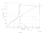
- FIG 13 one embodiment of a graph of displacement in inches in relation to force in lbs for a typical compression rod including rod ends with frictional bearings to which an axially oriented compressive force is applied is shown.
- An x-axis X1 shows a force applied to the typical compression rod.
- a y-axis Y1 shows a displacement of the typical compression rod.
- the typical compression rod has a slenderness ratio between 90 and 100.
- the load at which the ideal compression rod with frictionless ends was predicted to fail P is approximately 1800 lbf.
- the failure load F that a compression rod without the buckling initiating feature 18 and with frictional bearings ranged from 1800 lbf to 4400 lbf.
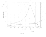
- FIG 14 one embodiment of a graph of displacement in inches in relation to force in lbs of the compression rod of the present invention 10 to which an axially oriented compressive force is applied is shown.
- An x-axis X1 shows a force applied to the compression rod of the present invention 10.
- a y-axis Y1 shows a displacement of the compression rod of the present invention.
- the compression rod of the present invention 10 has a baseline slenderness ratio between 90 and 100.
- the failure load P that the compression rod of the present invention, with frictionless ends, 10 was predicted to fail at is approximately 1500 lbf.
- the load that the compression rod of the present invention failed at F was consistently within 5% of the predicted failure load P.
- the buckling initiating feature 18 of the compression rod of the present invention 10 included a surface depression having a substantially flat, axially extending base portion and a depth of 0.05 inches.
- the buckling initiating feature 18 includes a surface depression having a substantially flat, axially extending base portion and a depth of 0.05 inches
- the present invention is not limited in this regard, as any suitable depth of the surface depression and any suitable configuration of surface depression may be used.
Landscapes
- Engineering & Computer Science (AREA)
- General Engineering & Computer Science (AREA)
- Mechanical Engineering (AREA)
- Shafts, Cranks, Connecting Bars, And Related Bearings (AREA)
Abstract
Description
- The present invention relates generally to a compression rod, and more specifically to a compression rod having a buckling initiating feature that is used to more precisely control the load at which the compression rod fails when frictional bearings are used at each end of the rod.
- A compression rod is a type of mechanical linkage that is configured to deform upon application of a predetermined force. Compression rods are often used in such applications as fixed wing and rotary wing aircrafts, wherein compression rods are used to connect control devices that enable the aircraft to be maneuvered. Buckling is a phenomenon in compression rods whereby a mechanical structure deforms under axial, compressive loading, but because of the deformation there is a critical load beyond which the rod cannot carry additional load. If friction is introduced by bearings positioned at each end of the rod, the rod can hold a higher load than the predicted critical buckling load until the static frictional force is overcome. When the static frictional force is overcome, buckling commences, and the load immediately drops to the predicted critical buckling load, wherein large deformations are evident.
- When a predetermined, axially oriented force is applied to a compression rod, buckling generally needs to be avoided in order for the rod to carry the load safely. Such avoidance is accomplished by increasing the area of the rod's cross-section, thereby increasing the weight of the rod. There are times, however, when, to prevent damage to more expensive components that the compression rod is coupled to the less expensive compression rod is sacrificed. In this case, the compression rod must safely carry the required loads, but if loads become higher than a maximum limit, the rod buckles to protect the attached component from experiencing loads beyond a threshold, as such loads would cause irreparable damage.
- The critical load that causes buckling is calculated for a compression member for the case of frictionless ends (i.e. cannot support moments). The critical load that causes buckling, Fcrit , is given by the equation


- When bearings are positioned on ends of the compression rod, the critical load that causes buckling is difficult to predict. Many factors, including the eccentricity of the point of load application to the center of the rod's cross-section, influence the load at which the compression rod will fail. Even between two similar compression rods with simlilar frictional bearings on each end, the load at which each fails may be drastically different from the predicted failure load. In addition, similar compression rods with frictional bearings tend to lack repeatable actual failure loads. Those skilled in the relevant art have long sought, but have been unable to arrive at, a compression rod that consistently fails within a narrow range of the predicted failure load for the compression rod.
- In one aspect, the present invention resides in a compression rod having a buckling initiating feature. The compression rod includes an elongate body. The elongate body has a first cross sectional area along a first length of the elongate body and a second cross sectional area along a second length of the elongate body. The buckling initiating feature is defined, in part, by the second cross sectional area. The second cross sectional area is configured to cause predetermined buckling along the elongate body upon application of a predetermined axially oriented compressive force. Predetermined buckling occurs when, upon application of a predetermined axially oriented compressive force, the elongate body buckles as predicted.
- In one embodiment, the elongate body is hollow. In one embodiment, the elongate body is solid. In one embodiment, the compression rod includes at least one rod end positioned on an axial end of the elongate body. In one embodiment, the compression rod includes at least one rod end positioned on an axial end of the elongate body and at least one of the at least one rod end is threaded into an axial end of the elongate body. In one embodiment, the compression rod includes at least one rod end positioned on an axial end of the elongate body and at least one of the at least one rod end is integral with an axial end of the elongate body. In one embodiment, the compression rod includes at least one clevis joint positioned on an axial end of the elongate body. In one embodiment, the compression rod includes at least one clevis joint positioned on an axial end of the elongate body, and the clevis joint is threaded into an axial end of the elongate body. In one embodiment, the compression rod includes at least one clevis joint positioned on an axial end of the elongate body and the clevis joint is integral with an axial end of the elongate body.
- In one embodiment, the compression rod has a baseline slenderness ratio of greater than 200. In one embodiment, the compression rod has a baseline slenderness ratio between 50 and 200.
- In one embodiment, the second length comprises a surface depression extending axially therealong. In one embodiment, the axially extending surface depression has a substantially flat base portion. In one embodiment, the axially extending surface depression has a substantially concave base portion. In one embodiment, the second length comprises a transversely extending surface depression. In one embodiment, the transversely extending surface depression has a substantially concave base portion. In one embodiment, the transversely extending base portion extends approximately 180 degrees around a cylindrical outer surface of the elongate body.
- In one embodiment, the buckling initiating feature comprises an axially extending surface depression having a concave base portion, wherein the surface depression extends axially along 10% to 50% percent of a length of the elongate body. In one embodiment, the buckling initiating feature comprises a circumferentially extending surface depression having a concave base portion, wherein the surface depression extends about 180 degrees around the elongate body.
-
-
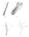
FIG. 1A is a front view of a compression rod having a buckling initiating feature of the present invention; -
FIG. 1B is a schematic view of the compression rod ofFIG. 1A , shown in a buckled condition; -
FIG. 1C is a schematic view of the compression rod ofFIG. 1A , shown in a buckled condition; -
FIG. 2 is a transverse cross sectional view of the compression rod ofFIG. 1A taken across the line 2-2; -
FIG. 3 is a transverse cross sectional view of one embodiment of a compression rod having a buckling initiating feature taken across the line 3-3; -
FIG. 4 is a front view of the compression rod having a buckling initiating feature of the present invention, wherein axially opposite rod ends are integral with the compression rod; -
FIG. 5A is a perspective view of the compression rod having a buckling feature of the present invention, wherein the buckling initiating feature comprises an axially extending surface depression having a substantially flat base portion; -
FIG. 5B is a perspective view of a portion of the compression rod having a buckling initiating feature ofFIG. 5A ; -
FIG. 6A is a perspective view of the compression rod having a buckling feature of the present invention, wherein the buckling feature includes an axially extending surface depression having a substantially concave base portion; -
FIG. 6B is a perspective view of a portion of the compression rod having a buckling initiating feature ofFIG. 6A ; -
FIG. 7A is a perspective view of the compression rod having a buckling initiating feature ofFIG. 1A , wherein the buckling feature includes a transversely extending surface depression having a substantially concave base portion; -
FIG. 7B is a perspective view of a portion of the compression rod having a buckling initiating feature ofFIG. 7A ; -
FIG. 8A is a perspective view of the compression rod having a buckling initiating feature ofFIG. 1A , wherein the buckling feature includes a surface depression extending partially circumferentially around the compression rod; -
FIG. 8B is a perspective view of a portion of the compression rod having a buckling initiating feature ofFIG. 8A ; -
FIG. 9A is a transverse cross sectional view of the compression rod ofFIG. 5A cut across the line W'-W' ofFIG. 9C ; -
FIG. 9B is a longitudinal cross sectional view of the compression rod ofFIG. 5A cut across the line W-W ofFIG. 9C ; -
FIG. 9C is a front view of the compression rod ofFIG. 5A ; -
FIG. 9D is a side view of the compression rod ofFIG. 5A ; -
FIG. 9E is a transverse cross sectional view of the compression rod ofFIG. 5A cut across the line W'-W' ofFIG. 9C , wherein the buckling initiating feature is in an alternative position; -
FIG. 10A is a transverse cross sectional view of the compression rod ofFIG. 6A cut across the line X'-X' ofFIG. 10C ; -
FIG. 10B is a longitudinal cross sectional view of the compression rod ofFIG. 6A cut across the line X-X ofFIG. 10C ; -
FIG. 10C is a front view of the compression rod ofFIG. 6A ; -
FIG. 10D is a side view of the compression rod ofFIG. 6A ; -
FIG. 10E is a transverse cross sectional view of the compression rod ofFIG. 6A cut across the line X'-X' ofFIG. 10C , wherein the buckling initiation feature is in an alternative position; -
FIG. 11A is a transverse cross sectional view of the compression rod ofFIG. 7A cut across the line Y'-1'' ofFIG. 11C ; -
FIG. 11B is a longitudinal cross sectional view of the compression rod ofFIG. 7A cut across the line Y-Y ofFIG. 11C ; -
FIG. 11C is a front view of the compression rod ofFIG. 7A ; -
FIG. 11D is a side view of the compression rod ofFIG. 7A ; -
FIG. 11E is a transverse cross sectional view of the compression rod ofFIG. 7A cut across the line Y'-Y' ofFIG. 11C , wherein the buckling initiating feature is in an alternative position; -
FIG. 12A is a transverse cross sectional view of the compression rod ofFIG. 8A cut across the line Z'-Z' ofFIG. 12C ; -
FIG. 12B is a longitudinal cross sectional view of the compression rod ofFIG. 8A cut across the line Z-Z ofFIG. 12C ; -
FIG. 12C is a front view of the compression rod ofFIG. 8A ; -
FIG. 12D is a side view of the compression rod ofFIG. 8A ; -
FIG. 12E is a transverse cross sectional view of the compression rod ofFIG. 8A cut across the line Z'-Z' ofFIG. 12C , wherein the buckling initiation feature is in an alternative position; -
FIG. 13 is a graph of deformation of a typical compression rod in relation to a force applied to the typical compression rod; and -
FIG. 14 is a graph of deformation of the compression rod of the present invention in relation to a force applied to the compression rod of the present invention. - As shown in
FIG. 1A , a compression rod is generally designated by the numeral 10. Thecompression rod 10 includes an elongate body 12 (e.g., a hollow tubular body) having a total length L. A first length L1 and L1', a second length L2 and acenter 14 are defined along the total length L. In the embodiment ofFIG. 1A , thecenter 14 is positioned equidistant from axially opposite ends 16A and 16B of theelongate body 12 and defines a plane C which extends therethrough. The second length L2 defines a buckling initiatingfeature 18, for example anasymmetrically positioned (e.g., present on one portion of the compression rod but not on an opposite side thereof) buckling feature as shown inFIGS. 1A, 3, 4 ,5A, 5B ,6A, 6B, 7A, 7B ,8A, 8B ,9A-9E ,10A-10E ,11A-11E , and12A-12E . It is not required that this surface be centered on the elongate body, but if it is not centered on the elongate body, the rod will deform less predictably.. The buckling initiatingfeature 18 is configured to cause predetermined buckling along the elongate body upon application of a predetermined axially oriented compressive force. Predetermined buckling occurs when, upon the application of the predetermined axially oriented compressive force, theelongate body 12 buckles as predicted. As shown inFIG. 1A , thecompression rod 10 includes two rod ends 20A and 20B secured thereto, as discussed further herein. Theelongate body 12 defines a generally cylindricalouter surface 22A and a cylindricalinner surface 22B. Although thecompression rod 10 is described as being hollow, the present invention is not limited in this regard, as asolid compression rod 10 may be used without departing from the broader aspects of the present invention. - Referring to
FIG. 2 , theelongate body 12 has a first crosssectional area 24A defined by a first outer diameter. The first crosssectional area 24A and the first outer diameter are present along a first axially orientedaxis 26 and along the first length L1 and L1'. A predetermined axially oriented force F is applied along the first axially orientedaxis 26. The buckling initiatingfeature 18 defines a second cross sectional area 24B. The second cross sectional area 24B is present along the second length L2. The second cross sectional area 24B is asymmetric and has less area than the first crosssectional area 24A. The second cross sectional area 24B is configured to cause buckling along theelongate body 12 upon application of the predetermined, axially oriented compressive force F. In one embodiment, as shown inFIG. 2 , the axially oriented compressive force F is distributed about the first crosssectional area 24A such that a resultant load transmission (i.e., load path) axis is coaxial with the first axially orientedaxis 26. - The
compression rod 10, illustrated inFIG. 1A , has a baseline slenderness ratio. The baseline slenderness ratio is a function of length and radius of gyration of thecompression rod 10. In one embodiment, the baseline slenderness ratio is between 50 and 200. In one embodiment, the baseline slenderness ratio is greater than 200. A compression rod with a baseline slenderness ratio between 50 and 200 that has no buckling initiating feature will fail by buckling. However, the failure load would have significantly more scatter (i.e., inconsistency) than would a rod with slenderness ratio of greater than 200 to which such a load was applied. A compression rod with a baseline slenderness ratio less than 50 that has no buckling initiating feature will likely fail by direct compression rather than by buckling. - In one embodiment, as shown in
FIG. 3 , the second cross sectional area 24B causes an eccentricity E between the first axially orientedaxis 26 and a second axially orientedaxis 28. The second axially orientedaxis 28 is defined by the centroid of the second crosssectional area 22B extending along the length L2. As shown inFIG. 3 , the first axially orientedaxis 26 and the second axially orientedaxis 28 are separated by the eccentricity E. The buckling initiatingfeature 18 causes the eccentricity E in a direction D, as a result of the second cross sectional area 24B being asymmetric and less than the first crosssectional area 24A. The eccentricity E between the first axially orientedaxis 26 and the second axially orientedaxis 28 increases the propensity of thecompression rod 10 to fail predictably in buckling as shown, for example, inFIG. 1B . The buckling initiatingfeature 18 is configured to cause the buckling before plastic axial compression of theelongate body 12. As shown inFIG. 1B , upon application of the compressive forces F to thecompression rod 10, when the compressive forces F reach a first predetermined magnitude, thecompression rod 10 buckles so that a portion of the compression rod 10 (e.g., a central portion or portion having the bucklinginitiation feature 18 therein) elastically buckles traversely in the direction of the arrow B. When the force F is of a first predetermined magnitude the buckling is in an elastic range so that when the force F is removed thecompression rod 10 elastically returns to an initial state as shown inFIG. 1A . When the force F' is increased to a second predetermined magnitude, greater than the first predetermined magnitude, thecompression rod 10 plastically buckles in the transverse direction indicated by the arrow B, as shown inFIG. 1C . After removal of the force F' thecompression rod 10 remains traversely buckled. Eccentricity E is created in acompression rod 10 without altering the load application points via the buckling initiatingfeature 18,. Thecompression rod 10 has a greater strength in tension than in compression. Compression rods may be easily retrofitted with the buckling initiatingfeature 18. - The eccentricity E between the first axially oriented
axis 26 and the second axially orientedaxis 28 increases the propensity for buckling of theelongatebody 12. This increased propensity for buckling of theelongate body 12 overcomes the friction in the frictional bearings in a consistent way. In one embodiment, the eccentricity E causes the axially oriented compressive force at which buckling occurs along theelongate body 12 to be within 5% of a predicted (e.g., analytically calculated) force at which buckling is predicted to occur when there is no friction on each end. - In one embodiment, the degree of the eccentricity E between the first axially oriented
axis 26 and the second axially orientedaxis 28 is approximately 0.020 to 0.030 inches where the outer diameter of theelongate body 12 along the first length L1 and L1' is 0.625 inches (e.g., 3.2 to 4.8% of the outer diameter). Although in one embodiment, the degree of the eccentricity E between the first axially orientedaxis 26 and the second axially orientedaxis 28 is 0.025 inches or 4.0% of the outer diameter, the present invention is not limited in this regard, as any suitable degree of eccentricity may be used, and greater degrees of eccentricity result in greater predictability regarding the onset of buckling, for example, when the elongate body is supported by frictional bearings. - As shown in
FIG. 1A , the buckling initiatingfeature 18 is positioned substantially equidistant from the opposing ends 16A and 16B of theelongate body 12 and symmetric about the plane C. In one embodiment, the buckling initiatingfeature 18 is positioned so that at a portion thereof extends axially through the plane C and is asymmetric thereto. However, the present invention is not limited in this regard, as the buckling initiating feature may be positioned so that no portion thereof extends axially through the plane C defined by thecenter 14 of theelongate body 12, for example an asymmetrically positioned bucklinginitiation feature 18. - In one embodiment, as shown in
FIG. 1A , thecompression rod 10 includes arod end elongate body 12. However, the present invention is not limited in this regard, as the compression rod may include onerod end end elongate body 12, or may include no rod ends positioned on theends elongate body 12. As shown inFIG. 1A , the rod ends 20A and 20B are threaded to thecompression rod 10. As shown inFIG. 4 , the rod ends 20A and 20B are integral with thecompression rod 10. - Similarly, in another embodiment, the
compression rod 10 includes a clevis joint 30 positioned on each of two axially opposite ends 16A and 16B of theelongate body 12. However, the present invention is not limited in this regard, as the compression rod may include the clevis joint 30 positioned on only oneend elongate body 12, as shown inFIG. 6B . In one embodiment, the clevis joints 30 are threaded to thecompression rod 10. In an alternative embodiment, the clevis joints 30 are integral with thecompression rod 10. - In an alternative embodiment, as illustrated in
FIG. 5A , thecompression rod 10 includes the rod end 20A positioned on the axiallyopposite end 16A and the clevis joint 30 positioned on the axiallyopposite end 16B. - In one embodiment, as shown in
FIGS. 5A-B and9A-E , the buckling initiatingfeature 18 is an axially extending surface depression having a substantially flat base portion. In one embodiment, thesurface depression 18 extends axially along 10% to 50% of the length of the elongate body. Thesurface depression 18 is positioned along a portion of the generally cylindricalouter surface 22A defined by the arc J-J, as shown inFIG. 9A . The present invention is not limited in this regard however, as the surface depression may be positioned along any suitable portion of the generally cylindricalouter surface 22A, for example along the generally cylindrical outer surface portion defined by the arc J'-J', as shown inFIG. 9E . - In one embodiment, as shown in
FIGS. 6A-B and10A-E , the buckling initiatingfeature 18 is an axially extending surface depression having a substantially concave base portion. In one embodiment, thesurface depression 18 extends axially along 10% to 50% of the length of the elongate body. Thesurface depression 18 is positioned along a portion of the generally cylindricalouter surface 22A defined by the arc K-K. The present invention is not limited in this regard however, as the surface depression may be positioned along any suitable portion of the generally cylindricalouter surface 22A, for example along the generally cylindrical outer surface portion defined by the arc K'-K', as shown inFIG. 10E . - In one embodiment, as shown in
FIGS. 7A-B and11A-E , the buckling initiatingfeature 18 is a transversely extending surface depression having a substantially concave base portion. In one embodiment, thesurface depression 18 extends transversely along the length of the elongate body. Thesurface depression 18 is positioned along a portion of the generally cylindricalouter surface 22A defined by the arc M-M. The present invention is not limited in this regard however, as the surface depression may be positioned along any suitable portion of the generally cylindricalouter surface 22A, for example along the generally cylindrical outer surface portion defined by the arc M'-M', as shown inFIG. 11E . - In one embodiment, as shown in
FIGS. 8A-B and12A-E , the buckling initiatingfeature 18 is a partially circumferentially extending surface depression having a substantially concave base portion. In one embodiment, thesurface depression 18 extends axially along the length of the elongate body. Thesurface depression 18 is positioned along a portion of the generally cylindricalouter surface 22A defined by the arc N-N. The present invention is not limited in this regard however, as the surface depression may be positioned along any suitable portion of the generally cylindricalouter surface 22A, for example along the generally cylindrical outer surface portion defined by the arc N'-N', as shown inFIG. 11E . In one embodiment, as shown inFIGS. 12A-12E , thesurface depression 18 extends approximately 180 degrees around the generally cylindricalouter surface 22A. The present invention is not limited in this regard however, as thesurface depression 18 may extend around the generally cylindricalouter surface 22A at any suitable angle without departure from the broader aspects of the present invention. - With reference to
FIG 13 , one embodiment of a graph of displacement in inches in relation to force in lbs for a typical compression rod including rod ends with frictional bearings to which an axially oriented compressive force is applied is shown. An x-axis X1 shows a force applied to the typical compression rod. A y-axis Y1 shows a displacement of the typical compression rod. In one embodiment, the typical compression rod has a slenderness ratio between 90 and 100. The load at which the ideal compression rod with frictionless ends was predicted to fail P is approximately 1800 lbf. The failure load F that a compression rod without the buckling initiatingfeature 18 and with frictional bearings ranged from 1800 lbf to 4400 lbf. - With reference to
FIG 14 , one embodiment of a graph of displacement in inches in relation to force in lbs of the compression rod of thepresent invention 10 to which an axially oriented compressive force is applied is shown. An x-axis X1 shows a force applied to the compression rod of thepresent invention 10. A y-axis Y1 shows a displacement of the compression rod of the present invention. In one embodiment, the compression rod of thepresent invention 10 has a baseline slenderness ratio between 90 and 100. The failure load P that the compression rod of the present invention, with frictionless ends, 10 was predicted to fail at is approximately 1500 lbf. The load that the compression rod of the present invention failed at F was consistently within 5% of the predicted failure load P. In one embodiment, the buckling initiatingfeature 18 of the compression rod of thepresent invention 10 included a surface depression having a substantially flat, axially extending base portion and a depth of 0.05 inches. - Although in one embodiment, the buckling initiating
feature 18 includes a surface depression having a substantially flat, axially extending base portion and a depth of 0.05 inches, the present invention is not limited in this regard, as any suitable depth of the surface depression and any suitable configuration of surface depression may be used. - Although the present invention has been disclosed and described with reference to certain embodiments thereof, it should be noted that other variations and modifications may be made, and it is intended that the following claims cover the variations and modifications within the true scope of the invention.
Claims (15)
- A compression rod having a buckling initiating feature, the compression rod comprising:an elongate body;the elongate body having a first cross sectional area along a first a length thereof and a second cross sectional area along a second length thereof; andthe buckling initiating feature comprising the second cross sectional area, the second cross sectional area being configured to cause predetermined buckling along the elongate body upon application of a predetermined axially oriented compressive force.
- The compression rod of claim 1, wherein the buckling initiation feature is asymmetrically positioned on the elongate body.
- The compression rod of claim 1, wherein the buckling initiating feature is configured to cause the buckling before plastic axial compression of the elongate body.
- The compression rod of claim 1, wherein the second cross sectional area is configured to cause the buckling in a direction traverse to a longitudinal axis of the compression rod.
- The compression rod of claim 1, wherein the second cross sectional area causes an eccentricity between;
a first axially oriented axis along which the predetermined axially oriented force is applied, and
a second axially oriented axis defined by a centroid of the second cross sectional area. - The compression rod of claim 1, wherein the elongate body is one of hollow and solid.
- The compression rod of claim 1, wherein the buckling initiating feature is positioned substantially equidistant from opposing axial ends of the elongate body.
- The compression rod of claim 1, wherein the compression rod includes at least one of a rod end and a clevis joint positioned on an axial end of the elongate body.
- The compression rod of claim 1, wherein the compression rod includes a rod end positioned on an axial end of the elongate body and the clevis joint positioned on an opposing end of the elongate body.
- The compression rod of claim 1, wherein the buckling initiating feature comprises an axially extending surface depression having a substantially flat base portion.
- The compression rod of claim 10, wherein the surface depression extends axially along 10% to 50% percent of a length of the elongate body.
- The compression rod of claim 1, wherein the buckling initiating feature comprises an axially extending surface depression having a concave base portion.
- The compression rod of claim 1, wherein the buckling initiating feature comprises a transversely extending surface depression having a concave base portion.
- The compression rod of claim 1, wherein the buckling initiating feature comprises a circumferentially extending surface depression having a concave base portion.
- The compression rod of claim 5, wherein the first cross sectional area defines a first outer diameter and the eccentricity is about 3.2 to 4.8% of the outer diameter.
Applications Claiming Priority (1)
| Application Number | Priority Date | Filing Date | Title |
|---|---|---|---|
| US201461979760P | 2014-04-15 | 2014-04-15 |
Publications (2)
| Publication Number | Publication Date |
|---|---|
| EP2937579A1 true EP2937579A1 (en) | 2015-10-28 |
| EP2937579B1 EP2937579B1 (en) | 2018-07-11 |
Family
ID=53298101
Family Applications (1)
| Application Number | Title | Priority Date | Filing Date |
|---|---|---|---|
| EP15163639.6A Not-in-force EP2937579B1 (en) | 2014-04-15 | 2015-04-15 | Compression rod having a buckling initiating feature |
Country Status (3)
| Country | Link |
|---|---|
| US (1) | US9909613B2 (en) |
| EP (1) | EP2937579B1 (en) |
| BR (1) | BR102015008428B1 (en) |
Families Citing this family (3)
| Publication number | Priority date | Publication date | Assignee | Title |
|---|---|---|---|---|
| JP7102761B2 (en) * | 2018-02-09 | 2022-07-20 | トヨタ自動車株式会社 | Manufacturing method of arm member |
| JP2019137207A (en) * | 2018-02-09 | 2019-08-22 | トヨタ自動車株式会社 | Suspension arm and manufacturing method therefor |
| US11421721B2 (en) * | 2019-08-22 | 2022-08-23 | The Boeing Company | Tie-rod assembly with adjustable length |
Citations (3)
| Publication number | Priority date | Publication date | Assignee | Title |
|---|---|---|---|---|
| US4334693A (en) * | 1978-10-18 | 1982-06-15 | Daimler-Benz Aktiengesellschaft | Independent front wheel suspension for motor vehicles |
| US5065976A (en) * | 1989-10-31 | 1991-11-19 | Hughes Aircraft Company | Support structure |
| US6298962B1 (en) * | 1998-03-13 | 2001-10-09 | Showa Denko K.K. | Member for arm |
Family Cites Families (20)
| Publication number | Priority date | Publication date | Assignee | Title |
|---|---|---|---|---|
| US3430541A (en) | 1967-03-28 | 1969-03-04 | Us Army | Compression rod actuator |
| US4156997A (en) * | 1975-07-14 | 1979-06-05 | Decker Bert J | Light weight tension-compression equilibrium structures |
| US4361212A (en) | 1980-12-11 | 1982-11-30 | The Boeing Company | Bidirectional mechanical load limiter |
| US4433224A (en) | 1982-10-18 | 1984-02-21 | Honeywell Inc. | Actuator mechanism with enhanced tactile characteristics |
| DE4028448A1 (en) | 1990-09-07 | 1992-03-12 | Suspa Compart Ag | REVERSIBLE IMPACT DAMPER, ESPECIALLY FOR MOTOR VEHICLES |
| DE4413636C2 (en) | 1994-04-20 | 1997-07-31 | Daimler Benz Ag | Strut |
| JP3828329B2 (en) | 2000-02-18 | 2006-10-04 | 日産自動車株式会社 | Auto body structure |
| FR2829546B1 (en) | 2001-09-11 | 2004-02-20 | Eurocopter France | ENERGY ABSORPTION CONNECTION BAR, AND ITS APPLICATION AS A TRANSMISSION BOX SUSPENSION BAR FOR AIRCRAFT |
| FR2840041B1 (en) | 2002-05-23 | 2004-07-16 | Snecma Moteurs | FUSE LINK WITH SHOCK ABSORBER AND STOPPER |
| EP1870318B1 (en) | 2006-06-21 | 2008-12-17 | Ford Global Technologies, LLC | Vehicle pillar and vehicle |
| DE102007011489A1 (en) | 2007-03-07 | 2008-09-11 | Kiefel Gmbh | Overload protection, drive train with such overload protection device for producing and / or processing a workpiece and method for applying labor |
| DE102007015909A1 (en) * | 2007-04-02 | 2008-10-09 | Mt Aerospace Ag | Process for producing fiber-reinforced hollow bodies |
| FR2918134B1 (en) * | 2007-06-28 | 2009-09-18 | Eads Europ Aeronautic Defence | STRUCTURAL ROD IN COMPOSITE MATERIAL AND METHOD FOR PRODUCING A ROD IN COMPOSITE MATERIAL |
| US8161619B2 (en) | 2007-11-02 | 2012-04-24 | The Boeing Company | Joint for hybrid composite items |
| WO2011117546A1 (en) * | 2010-03-25 | 2011-09-29 | Epsilon Composite | Method for the continuous production of a connecting part made from composite material |
| FR2965850B1 (en) | 2010-10-11 | 2012-12-14 | Airbus Operations Sas | SAFETY LINK DEVICE AND AIRCRAFT EQUIPPED WITH SUCH A SAFETY LINK DEVICE |
| BRPI1103745A2 (en) | 2011-08-30 | 2013-08-13 | Whirlpool Sa | reciprocating compressor connecting rod |
| JP5926096B2 (en) | 2012-03-30 | 2016-05-25 | 住友理工株式会社 | Torque rod |
| DE102013004010B4 (en) * | 2013-03-08 | 2016-02-18 | Audi Ag | Achslenker for a motor vehicle |
| GB2513317B (en) | 2013-04-22 | 2020-11-04 | Actuant Operations Uk Ltd | Failsafe mechanism |
-
2015
- 2015-04-14 US US14/686,413 patent/US9909613B2/en not_active Expired - Fee Related
- 2015-04-15 EP EP15163639.6A patent/EP2937579B1/en not_active Not-in-force
- 2015-04-15 BR BR102015008428-5A patent/BR102015008428B1/en not_active IP Right Cessation
Patent Citations (3)
| Publication number | Priority date | Publication date | Assignee | Title |
|---|---|---|---|---|
| US4334693A (en) * | 1978-10-18 | 1982-06-15 | Daimler-Benz Aktiengesellschaft | Independent front wheel suspension for motor vehicles |
| US5065976A (en) * | 1989-10-31 | 1991-11-19 | Hughes Aircraft Company | Support structure |
| US6298962B1 (en) * | 1998-03-13 | 2001-10-09 | Showa Denko K.K. | Member for arm |
Also Published As
| Publication number | Publication date |
|---|---|
| US9909613B2 (en) | 2018-03-06 |
| EP2937579B1 (en) | 2018-07-11 |
| US20150292549A1 (en) | 2015-10-15 |
| BR102015008428B1 (en) | 2022-04-05 |
| BR102015008428A2 (en) | 2016-05-31 |
Similar Documents
| Publication | Publication Date | Title |
|---|---|---|
| EP2937579B1 (en) | Compression rod having a buckling initiating feature | |
| US9618072B2 (en) | Shock damping element | |
| JP7072074B2 (en) | Fastener urging system | |
| CN104955711B (en) | Steering-column device | |
| US20130236234A1 (en) | Dual tube frangible joint | |
| US20160031278A1 (en) | Axle link for a motor vehicle | |
| EP1924775A2 (en) | Blind rivet and method | |
| EP3045378B1 (en) | Telescopic shaft and steering system | |
| JP2017180072A (en) | Joint for steel pipe pile | |
| CA3011749A1 (en) | Aircraft assembly with safety guide | |
| US9944144B2 (en) | Spring and damper systems for attenuating the transmission of energy | |
| EP3274195B1 (en) | Spring and damper systems for attenuating the transmission of energy | |
| EP4033111B1 (en) | Frangible fastener system | |
| EP3121480B1 (en) | Isolators including main spring linear guide systems | |
| EP3524450B1 (en) | Arm component and manufacturing method therefor | |
| RU2522787C1 (en) | Device of fixing in fold position of wing panels of unmanned aerial vehicle | |
| EP2147828A1 (en) | Low shock frangible joint | |
| EP3922562B1 (en) | A vibration isolation device, especially for aircraft applications | |
| US20150246854A1 (en) | Fully-redundant frangible separation system | |
| US10040477B2 (en) | Tie rod | |
| US11131357B2 (en) | Torsion bar spring | |
| EP3172116B1 (en) | Tie rod | |
| DE112021003320T5 (en) | COMPENSATOR | |
| EP3222865B1 (en) | Universal joint with simplified structure | |
| US8157216B2 (en) | Methods and apparatus for an asymmetrical fairing |
Legal Events
| Date | Code | Title | Description |
|---|---|---|---|
| PUAI | Public reference made under article 153(3) epc to a published international application that has entered the european phase |
Free format text: ORIGINAL CODE: 0009012 |
|
| AK | Designated contracting states |
Kind code of ref document: A1 Designated state(s): AL AT BE BG CH CY CZ DE DK EE ES FI FR GB GR HR HU IE IS IT LI LT LU LV MC MK MT NL NO PL PT RO RS SE SI SK SM TR |
|
| AX | Request for extension of the european patent |
Extension state: BA ME |
|
| 17P | Request for examination filed |
Effective date: 20160422 |
|
| RBV | Designated contracting states (corrected) |
Designated state(s): AL AT BE BG CH CY CZ DE DK EE ES FI FR GB GR HR HU IE IS IT LI LT LU LV MC MK MT NL NO PL PT RO RS SE SI SK SM TR |
|
| STAA | Information on the status of an ep patent application or granted ep patent |
Free format text: STATUS: EXAMINATION IS IN PROGRESS |
|
| 17Q | First examination report despatched |
Effective date: 20170515 |
|
| GRAP | Despatch of communication of intention to grant a patent |
Free format text: ORIGINAL CODE: EPIDOSNIGR1 |
|
| STAA | Information on the status of an ep patent application or granted ep patent |
Free format text: STATUS: GRANT OF PATENT IS INTENDED |
|
| INTG | Intention to grant announced |
Effective date: 20180309 |
|
| GRAS | Grant fee paid |
Free format text: ORIGINAL CODE: EPIDOSNIGR3 |
|
| GRAA | (expected) grant |
Free format text: ORIGINAL CODE: 0009210 |
|
| STAA | Information on the status of an ep patent application or granted ep patent |
Free format text: STATUS: THE PATENT HAS BEEN GRANTED |
|
| AK | Designated contracting states |
Kind code of ref document: B1 Designated state(s): AL AT BE BG CH CY CZ DE DK EE ES FI FR GB GR HR HU IE IS IT LI LT LU LV MC MK MT NL NO PL PT RO RS SE SI SK SM TR |
|
| REG | Reference to a national code |
Ref country code: GB Ref legal event code: FG4D |
|
| REG | Reference to a national code |
Ref country code: CH Ref legal event code: EP |
|
| REG | Reference to a national code |
Ref country code: AT Ref legal event code: REF Ref document number: 1017179 Country of ref document: AT Kind code of ref document: T Effective date: 20180715 |
|
| REG | Reference to a national code |
Ref country code: IE Ref legal event code: FG4D |
|
| REG | Reference to a national code |
Ref country code: DE Ref legal event code: R096 Ref document number: 602015013243 Country of ref document: DE |
|
| REG | Reference to a national code |
Ref country code: NL Ref legal event code: MP Effective date: 20180711 |
|
| REG | Reference to a national code |
Ref country code: LT Ref legal event code: MG4D |
|
| REG | Reference to a national code |
Ref country code: AT Ref legal event code: MK05 Ref document number: 1017179 Country of ref document: AT Kind code of ref document: T Effective date: 20180711 |
|
| PG25 | Lapsed in a contracting state [announced via postgrant information from national office to epo] |
Ref country code: NL Free format text: LAPSE BECAUSE OF FAILURE TO SUBMIT A TRANSLATION OF THE DESCRIPTION OR TO PAY THE FEE WITHIN THE PRESCRIBED TIME-LIMIT Effective date: 20180711 |
|
| PG25 | Lapsed in a contracting state [announced via postgrant information from national office to epo] |
Ref country code: AT Free format text: LAPSE BECAUSE OF FAILURE TO SUBMIT A TRANSLATION OF THE DESCRIPTION OR TO PAY THE FEE WITHIN THE PRESCRIBED TIME-LIMIT Effective date: 20180711 Ref country code: BG Free format text: LAPSE BECAUSE OF FAILURE TO SUBMIT A TRANSLATION OF THE DESCRIPTION OR TO PAY THE FEE WITHIN THE PRESCRIBED TIME-LIMIT Effective date: 20181011 Ref country code: PL Free format text: LAPSE BECAUSE OF FAILURE TO SUBMIT A TRANSLATION OF THE DESCRIPTION OR TO PAY THE FEE WITHIN THE PRESCRIBED TIME-LIMIT Effective date: 20180711 Ref country code: LT Free format text: LAPSE BECAUSE OF FAILURE TO SUBMIT A TRANSLATION OF THE DESCRIPTION OR TO PAY THE FEE WITHIN THE PRESCRIBED TIME-LIMIT Effective date: 20180711 Ref country code: NO Free format text: LAPSE BECAUSE OF FAILURE TO SUBMIT A TRANSLATION OF THE DESCRIPTION OR TO PAY THE FEE WITHIN THE PRESCRIBED TIME-LIMIT Effective date: 20181011 Ref country code: GR Free format text: LAPSE BECAUSE OF FAILURE TO SUBMIT A TRANSLATION OF THE DESCRIPTION OR TO PAY THE FEE WITHIN THE PRESCRIBED TIME-LIMIT Effective date: 20181012 Ref country code: IS Free format text: LAPSE BECAUSE OF FAILURE TO SUBMIT A TRANSLATION OF THE DESCRIPTION OR TO PAY THE FEE WITHIN THE PRESCRIBED TIME-LIMIT Effective date: 20181111 Ref country code: RS Free format text: LAPSE BECAUSE OF FAILURE TO SUBMIT A TRANSLATION OF THE DESCRIPTION OR TO PAY THE FEE WITHIN THE PRESCRIBED TIME-LIMIT Effective date: 20180711 Ref country code: FI Free format text: LAPSE BECAUSE OF FAILURE TO SUBMIT A TRANSLATION OF THE DESCRIPTION OR TO PAY THE FEE WITHIN THE PRESCRIBED TIME-LIMIT Effective date: 20180711 Ref country code: SE Free format text: LAPSE BECAUSE OF FAILURE TO SUBMIT A TRANSLATION OF THE DESCRIPTION OR TO PAY THE FEE WITHIN THE PRESCRIBED TIME-LIMIT Effective date: 20180711 |
|
| PG25 | Lapsed in a contracting state [announced via postgrant information from national office to epo] |
Ref country code: LV Free format text: LAPSE BECAUSE OF FAILURE TO SUBMIT A TRANSLATION OF THE DESCRIPTION OR TO PAY THE FEE WITHIN THE PRESCRIBED TIME-LIMIT Effective date: 20180711 Ref country code: ES Free format text: LAPSE BECAUSE OF FAILURE TO SUBMIT A TRANSLATION OF THE DESCRIPTION OR TO PAY THE FEE WITHIN THE PRESCRIBED TIME-LIMIT Effective date: 20180711 Ref country code: AL Free format text: LAPSE BECAUSE OF FAILURE TO SUBMIT A TRANSLATION OF THE DESCRIPTION OR TO PAY THE FEE WITHIN THE PRESCRIBED TIME-LIMIT Effective date: 20180711 Ref country code: HR Free format text: LAPSE BECAUSE OF FAILURE TO SUBMIT A TRANSLATION OF THE DESCRIPTION OR TO PAY THE FEE WITHIN THE PRESCRIBED TIME-LIMIT Effective date: 20180711 |
|
| REG | Reference to a national code |
Ref country code: DE Ref legal event code: R097 Ref document number: 602015013243 Country of ref document: DE |
|
| PG25 | Lapsed in a contracting state [announced via postgrant information from national office to epo] |
Ref country code: IT Free format text: LAPSE BECAUSE OF FAILURE TO SUBMIT A TRANSLATION OF THE DESCRIPTION OR TO PAY THE FEE WITHIN THE PRESCRIBED TIME-LIMIT Effective date: 20180711 Ref country code: EE Free format text: LAPSE BECAUSE OF FAILURE TO SUBMIT A TRANSLATION OF THE DESCRIPTION OR TO PAY THE FEE WITHIN THE PRESCRIBED TIME-LIMIT Effective date: 20180711 Ref country code: CZ Free format text: LAPSE BECAUSE OF FAILURE TO SUBMIT A TRANSLATION OF THE DESCRIPTION OR TO PAY THE FEE WITHIN THE PRESCRIBED TIME-LIMIT Effective date: 20180711 Ref country code: RO Free format text: LAPSE BECAUSE OF FAILURE TO SUBMIT A TRANSLATION OF THE DESCRIPTION OR TO PAY THE FEE WITHIN THE PRESCRIBED TIME-LIMIT Effective date: 20180711 |
|
| PLBE | No opposition filed within time limit |
Free format text: ORIGINAL CODE: 0009261 |
|
| STAA | Information on the status of an ep patent application or granted ep patent |
Free format text: STATUS: NO OPPOSITION FILED WITHIN TIME LIMIT |
|
| PG25 | Lapsed in a contracting state [announced via postgrant information from national office to epo] |
Ref country code: SM Free format text: LAPSE BECAUSE OF FAILURE TO SUBMIT A TRANSLATION OF THE DESCRIPTION OR TO PAY THE FEE WITHIN THE PRESCRIBED TIME-LIMIT Effective date: 20180711 Ref country code: DK Free format text: LAPSE BECAUSE OF FAILURE TO SUBMIT A TRANSLATION OF THE DESCRIPTION OR TO PAY THE FEE WITHIN THE PRESCRIBED TIME-LIMIT Effective date: 20180711 Ref country code: SK Free format text: LAPSE BECAUSE OF FAILURE TO SUBMIT A TRANSLATION OF THE DESCRIPTION OR TO PAY THE FEE WITHIN THE PRESCRIBED TIME-LIMIT Effective date: 20180711 |
|
| 26N | No opposition filed |
Effective date: 20190412 |
|
| PG25 | Lapsed in a contracting state [announced via postgrant information from national office to epo] |
Ref country code: SI Free format text: LAPSE BECAUSE OF FAILURE TO SUBMIT A TRANSLATION OF THE DESCRIPTION OR TO PAY THE FEE WITHIN THE PRESCRIBED TIME-LIMIT Effective date: 20180711 |
|
| REG | Reference to a national code |
Ref country code: CH Ref legal event code: PL |
|
| REG | Reference to a national code |
Ref country code: BE Ref legal event code: MM Effective date: 20190430 |
|
| GBPC | Gb: european patent ceased through non-payment of renewal fee |
Effective date: 20190415 |
|
| PG25 | Lapsed in a contracting state [announced via postgrant information from national office to epo] |
Ref country code: LU Free format text: LAPSE BECAUSE OF NON-PAYMENT OF DUE FEES Effective date: 20190415 Ref country code: MC Free format text: LAPSE BECAUSE OF FAILURE TO SUBMIT A TRANSLATION OF THE DESCRIPTION OR TO PAY THE FEE WITHIN THE PRESCRIBED TIME-LIMIT Effective date: 20180711 |
|
| PG25 | Lapsed in a contracting state [announced via postgrant information from national office to epo] |
Ref country code: CH Free format text: LAPSE BECAUSE OF NON-PAYMENT OF DUE FEES Effective date: 20190430 Ref country code: GB Free format text: LAPSE BECAUSE OF NON-PAYMENT OF DUE FEES Effective date: 20190415 Ref country code: LI Free format text: LAPSE BECAUSE OF NON-PAYMENT OF DUE FEES Effective date: 20190430 |
|
| PG25 | Lapsed in a contracting state [announced via postgrant information from national office to epo] |
Ref country code: BE Free format text: LAPSE BECAUSE OF NON-PAYMENT OF DUE FEES Effective date: 20190430 Ref country code: FR Free format text: LAPSE BECAUSE OF NON-PAYMENT OF DUE FEES Effective date: 20190430 |
|
| PG25 | Lapsed in a contracting state [announced via postgrant information from national office to epo] |
Ref country code: TR Free format text: LAPSE BECAUSE OF FAILURE TO SUBMIT A TRANSLATION OF THE DESCRIPTION OR TO PAY THE FEE WITHIN THE PRESCRIBED TIME-LIMIT Effective date: 20180711 |
|
| PG25 | Lapsed in a contracting state [announced via postgrant information from national office to epo] |
Ref country code: IE Free format text: LAPSE BECAUSE OF NON-PAYMENT OF DUE FEES Effective date: 20190415 |
|
| PG25 | Lapsed in a contracting state [announced via postgrant information from national office to epo] |
Ref country code: PT Free format text: LAPSE BECAUSE OF FAILURE TO SUBMIT A TRANSLATION OF THE DESCRIPTION OR TO PAY THE FEE WITHIN THE PRESCRIBED TIME-LIMIT Effective date: 20181111 |
|
| PG25 | Lapsed in a contracting state [announced via postgrant information from national office to epo] |
Ref country code: CY Free format text: LAPSE BECAUSE OF FAILURE TO SUBMIT A TRANSLATION OF THE DESCRIPTION OR TO PAY THE FEE WITHIN THE PRESCRIBED TIME-LIMIT Effective date: 20180711 |
|
| PG25 | Lapsed in a contracting state [announced via postgrant information from national office to epo] |
Ref country code: HU Free format text: LAPSE BECAUSE OF FAILURE TO SUBMIT A TRANSLATION OF THE DESCRIPTION OR TO PAY THE FEE WITHIN THE PRESCRIBED TIME-LIMIT; INVALID AB INITIO Effective date: 20150415 Ref country code: MT Free format text: LAPSE BECAUSE OF FAILURE TO SUBMIT A TRANSLATION OF THE DESCRIPTION OR TO PAY THE FEE WITHIN THE PRESCRIBED TIME-LIMIT Effective date: 20180711 |
|
| PG25 | Lapsed in a contracting state [announced via postgrant information from national office to epo] |
Ref country code: MK Free format text: LAPSE BECAUSE OF FAILURE TO SUBMIT A TRANSLATION OF THE DESCRIPTION OR TO PAY THE FEE WITHIN THE PRESCRIBED TIME-LIMIT Effective date: 20180711 |
|
| PGFP | Annual fee paid to national office [announced via postgrant information from national office to epo] |
Ref country code: DE Payment date: 20220420 Year of fee payment: 8 |
|
| REG | Reference to a national code |
Ref country code: DE Ref legal event code: R119 Ref document number: 602015013243 Country of ref document: DE |
|
| PG25 | Lapsed in a contracting state [announced via postgrant information from national office to epo] |
Ref country code: DE Free format text: LAPSE BECAUSE OF NON-PAYMENT OF DUE FEES Effective date: 20231103 |