EP2937578A1 - Load carrier foot - Google Patents
Load carrier foot Download PDFInfo
- Publication number
- EP2937578A1 EP2937578A1 EP14165879.9A EP14165879A EP2937578A1 EP 2937578 A1 EP2937578 A1 EP 2937578A1 EP 14165879 A EP14165879 A EP 14165879A EP 2937578 A1 EP2937578 A1 EP 2937578A1
- Authority
- EP
- European Patent Office
- Prior art keywords
- engagement
- load carrier
- walls
- tensioning screw
- carrier foot
- Prior art date
- Legal status (The legal status is an assumption and is not a legal conclusion. Google has not performed a legal analysis and makes no representation as to the accuracy of the status listed.)
- Granted
Links
Images


Classifications
-
- B—PERFORMING OPERATIONS; TRANSPORTING
- B60—VEHICLES IN GENERAL
- B60R—VEHICLES, VEHICLE FITTINGS, OR VEHICLE PARTS, NOT OTHERWISE PROVIDED FOR
- B60R9/00—Supplementary fittings on vehicle exterior for carrying loads, e.g. luggage, sports gear or the like
- B60R9/04—Carriers associated with vehicle roof
- B60R9/058—Carriers associated with vehicle roof characterised by releasable attaching means between carrier and roof
-
- F—MECHANICAL ENGINEERING; LIGHTING; HEATING; WEAPONS; BLASTING
- F16—ENGINEERING ELEMENTS AND UNITS; GENERAL MEASURES FOR PRODUCING AND MAINTAINING EFFECTIVE FUNCTIONING OF MACHINES OR INSTALLATIONS; THERMAL INSULATION IN GENERAL
- F16B—DEVICES FOR FASTENING OR SECURING CONSTRUCTIONAL ELEMENTS OR MACHINE PARTS TOGETHER, e.g. NAILS, BOLTS, CIRCLIPS, CLAMPS, CLIPS OR WEDGES; JOINTS OR JOINTING
- F16B39/00—Locking of screws, bolts or nuts
- F16B39/02—Locking of screws, bolts or nuts in which the locking takes place after screwing down
- F16B39/10—Locking of screws, bolts or nuts in which the locking takes place after screwing down by a plate, spring, wire or ring immovable with regard to the bolt or object and mainly perpendicular to the axis of the bolt
- F16B39/101—Locking of screws, bolts or nuts in which the locking takes place after screwing down by a plate, spring, wire or ring immovable with regard to the bolt or object and mainly perpendicular to the axis of the bolt with a plate, spring, wire or ring holding two or more nuts or bolt heads which are mainly in the same plane
-
- F—MECHANICAL ENGINEERING; LIGHTING; HEATING; WEAPONS; BLASTING
- F16—ENGINEERING ELEMENTS AND UNITS; GENERAL MEASURES FOR PRODUCING AND MAINTAINING EFFECTIVE FUNCTIONING OF MACHINES OR INSTALLATIONS; THERMAL INSULATION IN GENERAL
- F16B—DEVICES FOR FASTENING OR SECURING CONSTRUCTIONAL ELEMENTS OR MACHINE PARTS TOGETHER, e.g. NAILS, BOLTS, CIRCLIPS, CLAMPS, CLIPS OR WEDGES; JOINTS OR JOINTING
- F16B39/00—Locking of screws, bolts or nuts
- F16B39/02—Locking of screws, bolts or nuts in which the locking takes place after screwing down
- F16B39/10—Locking of screws, bolts or nuts in which the locking takes place after screwing down by a plate, spring, wire or ring immovable with regard to the bolt or object and mainly perpendicular to the axis of the bolt
- F16B39/108—Locking of screws, bolts or nuts in which the locking takes place after screwing down by a plate, spring, wire or ring immovable with regard to the bolt or object and mainly perpendicular to the axis of the bolt with a locking washer under the nut or bolt head having at least one tongue or lug folded against the nut or bolt head, or against the object itself
Definitions
- the present subject matter relates to a load carrier foot.
- Known load carrier feet typically comprise a mounting structure for mounting the load carrier feet on a vehicle and a tensioning screw. By rotating the tensioning screw, elements of the mounting structure are moved with respect to each other so as to fix the load carrier foot on the vehicle and/or to fix a load carrier bar on the load carrier foot. In order to ensure a secure fixation, it is necessary to prevent the tensioning screw from coming loose.
- the present subject matter relates to a load carrier foot.
- the load carrier foot comprises a mounting structure for mounting the load carrier foot on a vehicle.
- the mounting structure can comprise a clamping mechanism for clamping the load carrier foot to a fixed roof rail or directly to the roof of the vehicle by gripping a body fold of the vehicle body.
- the load carrier further comprises a tightening means which is preferably a tensioning screw.
- the tightening means is adapted to actuate the clamping mechanism upon operation of the same.
- the mounting structure can comprise a through hole through which the tightening means, preferably the tensioning screw, is passed. That is, in case a tensioning screw is used, the lower end of the screw head can be brought into contact with the mounting structure exerting a pressing force against the same.
- the load carrier foot preferably comprises a locking mechanism for preventing the tightening means from coming loose.
- the locking mechanism can be a screw locking mechanism or thread lock mechanism for preventing the tensioning screw from coming loose.
- the tightening means which can be realized as tensioning screw can comprise an engagement portion formed in the outer periphery thereof.
- the locking mechanism - which can be the thread lock mechanism - preferably comprises an engagement device engageable with the engagement portion of the tightening means.
- the engagement portion and the engagement device can be correspondingly formed so as to be engageable with each other.
- engageable with each other is to be understood as the engagement portion and the engagement device being formed such that a contact there between is either directly established upon engagement or both elements are formed and placed with respect to each other such that a contact can at least occur under certain circumstances, e.g. upon a slight rotation of the tensioning screw.
- the contact between both elements blocks a movement of the tightening means or at least makes a movement of the tightening means more difficult. That is, the engagement device is suitable to apply a predetermined force on the engagement portion counteracting a rotational movement of the tensioning screw.
- the movement of the tightening means can be prevented by providing a form-fit between the tightening means and the locking mechanism.
- the locking mechanism can be constructed to apply a friction force on the tightening means in order to prevent a movement thereof, either fully or to a certain extent. Accordingly, it is possible to provide a locking mechanism which, when engaged, enables a movement of the tightening means when a predetermined force is exceeded.
- the thread lock mechanism can be engaged with the tensioning screw such that a predetermined torque has to be exceeded in order to rotate the tensioning screw. In case the predetermined torque is not reached, the tensioning screw cannot rotate. Accordingly, an unintentional loosening of the tensioning screw, for example caused by vibrations, is prevented.
- the engagement portion is formed in the outer periphery of the tensioning screw. Since the thread lock mechanism comprises an engagement device engageable with the engagement portion of the tensioning screw, the engagement device in this case contacts or is contactable with the outer periphery of the tensioning screw in the engagement portion. Accordingly, an engagement can be established by engaging the engagement device with the engagement portion from radially outside.
- the engagement portion is polygonally shaped, preferably hexagonally shaped. Accordingly, the engagement portion can comprise three or more flats and the engagement device can be constructed so as to get in contact with at least one flat or at least a portion of such a flat.
- the engagement device can be formed so as to at least partially comprise a shape corresponding to the outer periphery of the engagement portion.
- the engagement portion is hexagonally shaped, it is possible to use an engagement device which contacts three adjacent flats of the engagement portion. While a polygonally shaped engagement portion is most preferable, it is also possible to provide an engagement portion comprising a different shape as long as it is possible to provide an engagement between the engagement device and the engagement portion for preventing a rotation of the tensioning screw. Accordingly, it is possible to use an engagement portion comprising an outer periphery which is continuously formed and is non-circular, elliptical for instance.
- the engagement device comprises engagement walls contactable with the engagement portion and being moveable with respect to the engagement portion.
- the engagement walls can be formed by providing a protrusion on the engagement device.
- the engagement walls comprise flat surfaces.
- the width of the engagement walls can be formed so as to correspond to the width of a flat of the polygonal shape, that is, can have a width which is substantially identical to the width of one flat of the polygonal shape. It is furthermore possible to provide an engagement wall having a width which is smaller than the width of a flat of the polygonal shape.
- the height of the engagement walls can correspond to the dimension of the engagement portion in the longitudinal direction of the tensioning screw or can be smaller.
- the surface area of the engagement portion can be smaller than the surface area of one flat of the engagement portion.
- the height of the engagement wall is smaller than the dimension of the engagement device in the longitudinal direction, it is, for example, possible to keep the functionality of a screw head, that is to still enable a form-fit contact of a tool with the outer periphery of a screw head with the engagement wall arranged in place.
- the engagement walls can have an identical shape or can comprise different shapes.
- curled stops that is engagement device in which a sheet metal strip is rolled so that it comprises a spiral cross section.
- curled stops can be arranged so as to be or get in point or linear contact with the engagement portion depending on the shape of the same.
- the engagement walls are resilient.
- a resiliency of the engagement walls can be achieved either by choosing a specific material and/or by choosing a certain construction.
- an elastic material such as rubber can be used.
- the engagement walls are provided on opposite sides of the engagement portion. Accordingly, the engagement walls can be arranged to apply forces facing towards each other on the engagement portion. Such a construction provides a reliable force application on the engagement portion. Furthermore, since forces are applied from opposite sides, no bending moment is exerted on the tensioning screw.
- the engagement walls can be arranged with a space there between or can be arranged adjacent to each other. Accordingly, the walls can be formed integrally forming a corner portion at a transition from one engagement wall to the other.
- the angle corresponds to an angle spanned between two flats of the polygonally shaped engagement portion.
- the thread lock mechanism further comprises a swivel arm.
- the swivel arm can be mounted on the mounting structure pivotably about a pivot axis which is substantially parallel to the longitudinal axis of the tensioning screw.
- the swivel arm is pivotable in a pivot plane perpendicular to the pivot axis.
- the engagement device can be provided on the swivel arm and can be engageable with the engagement portion by a pivoting motion of the swivel arm in the pivot plane.
- the swivel arm can be mounted to the mounting structure at one end thereof and the engagement device can be provided at the other end thereof.
- the swivel arm can have an elongate shape and can comprise a straight or curved shape.
- the swivel arm is constructed such that it is pivotable in the pivot plane only.
- the swivel arm can be constructed and can be mounted in such a way that it is substantially not moveable in a direction perpendicular to the pivot plane.
- the engagement device is constructed so as to be able to accommodate the engagement portion therein by pivotably moving the swivel arm. That is, in the engagement portion, an opening can be formed in the leading end of the swivel arm.
- the swivel arm can further comprise an actuating portion which is suitably formed to be grasped by a user. Therefore, the user can move the swivel arm so as to engage the engagement device by means of the engagement portion.
- the swivel arm can be formed so as to have an abutment portion contactable with a cover of the load carrier foot.
- the cover of the load carrier foot can be formed with a stop either completely blocking the movement of the swivel arm or allowing a movement of the swivel arm to a certain extent while the thread locking function remains effective.
- the stop is formed so as to be contactable with the actuating portion.
- the stop can be a protrusion extending from a wall of the cover.
- the engagement device is formed as a claw-like portion adapted to partially surround the engagement portion.
- the claw-like formed engagement device can comprise at least two contact areas contactable with the outer surface of the engagement portion.
- two of the at least two contact areas are provided on opposite sides of the engagement portion.
- the engagement device comprises an opening which is open in the engagement direction.
- the swivel arm comprises a plate extending substantially in the pivot plane and walls extending substantially perpendicular to the plate.
- the engagement device can be formed by suitably arranging the walls. For example, it is possible to arrange the walls with a distance between the same so as to form a space in which the engagement portion can be accommodated.
- the walls can be integrally formed with the plate.
- the engagement device can be constructed such that the space provided between the walls used for engaging the engagement portion can be smaller than the maximum outer diameter of the engagement portion.
- the plate is provided over the entire range of the swivel arm.
- the walls forming the engagement device protrude from the plate.
- the plate does not range over the entire range of the swivel arm. According to this construction, it is possible to provide one wall protruding from the plate in a perpendicular direction and to provide another wall protruding radially and curved from the radial outer end of the plate.
- the plate covers the tensioning screw in case the engagement device is engaged with the engagement portion or to use a construction in which the claw-like portion protrudes from a radial end of the plate so that a hook is formed on the end of the swivel arm which is engageable with the engagement portion.
- the engagement device is lockably moveable in a direction perpendicular to the longitudinal axis of the tensioning screw.
- lockably moveable means that the engagement device is moveable as long as the movement is not blocked by a suitable blocking means.
- the movement can be blocked by means of an additional element.
- the load carrier foot can comprise a cover for covering the interior of the load carrier foot and the cover can be adapted to block the movement of the engagement device.
- the cover can comprise a protrusion getting near or contacting the engagement device upon mounting the same.
- the engagement device is moveable in a direction perpendicular to the longitudinal axis of the tensioning screw as long as the cover is not provided on the load carrier foot and in which the movement of the engagement device is blocked in case the cover is provided on the load carrier foot.
- the engagement device can comprise a base member and two walls protruding therefrom.
- both of the two walls extend substantially perpendicular to base member.
- the base member and the walls are guided so as to be moveable perpendicular to the longitudinal axis of the tensioning screw and are freely moveable as long as no cover is provided on the load carrier foot.
- the base member can comprise an opening through which the tensioning element, the tensioning screw for instance, is passed.
- the opening can comprises a width slightly larger than the outer diameter of a tensioning screw portion. With such a construction, the movability of the engagement device with respect to the tensioning screw is guaranteed.
- the opening comprises a length enabling the engagement device to move relative to the tensioning screw such that the two walls can move away from the engagement portion to an extent that the two walls do not block the rotation of the tensioning screw.
- the tensioning screw comprises a hexagonal outer shape and the walls of the engagement device are able to get in contact with two of the flats of the hexagonal shape.
- the engagement device is pushed away from the tensioning screw in case the same is rotated.
- the walls of the engagement device ride over the flats and edges of the hexagonal outer shape of the screw head. Accordingly, the tensioning screw is rotatable in case the cover is not provided on the load carrier foot.
- the movement of the engagement device is blocked so that the rotation of the tensioning screw cannot or at least cannot substantially effect a movement of the walls in the direction perpendicular to the longitudinal axis of the tensioning screw. Consequently, the walls exert a pushing force on or get in contact with the outer periphery of the tensioning screw and therefore prevent a rotation of the same.
- the engagement device is prestressed so as to continuously apply a force on the engagement portion in a direction perpendicular to the longitudinal axis of the tensioning screw.
- a spring element can be provided so as to prestress the engagement device or the engagement device can be constructed so as to comprise such a spring element function.
- the thread lock mechanism can comprise a blade spring and the engagement device can be provided on an end of the blade spring.
- the engagement device is moveable in the longitudinal direction of the blade spring against the blade spring force.
- the engagement device exerts a tensile or a pushing force on the engagement portion.
- an engagement device comprising a blade spring
- the engagement device can be provided on each end of the blade spring, one for each tensioning screw.
- Each of the two engagement device can comprise an opening for passing a tensioning screw there through.
- the opening has a width slightly larger than a corresponding supporting portion of the tensioning screw and a length enabling a movement of each engagement device relative to the tensioning screw so that the walls can be moved relative to the tensioning screws.
- the blade spring can be prestressed.
- the blade spring can be configured such that the walls of the engagement device are pushed against the engagement portion either by a tensile or a pushing force. It is, however, possible to use a construction in which a blade spring is used which is not prestressed. In this case, for effecting the locking action, it is necessary to push the blade spring so that the engaging means is engaged with the engagement portion of the tensioning screw.
- the engagement walls are arranged parallel to and spaced from each other. Accordingly, the engagement walls can be arranged on opposite sides of the engagement portion.
- the engagement portion comprises an even number of flats and the distance between the two engagement surfaces of the engagement walls is smaller than the maximum outer diameter of the engagement portion. Accordingly, the engagement surfaces can be arranged such that in case the engagement portion comprising an even number of flats is arranged such that the flats are in parallel to the engagement surfaces, a small gap is arranged between the engagement walls and the flats or the engagement surfaces contact the flats.
- the engagement device comprises an opening accommodating the tensioning screw.
- the engagement device can have a construction which allows the tensioning screw to pass the same.
- the engagement device can comprise a through hole through which the tensioning screw can be passed.
- the through hole can comprise an elongate shape.
- the engagement device is adapted to apply a predetermined torque on the engaging portion wherein the predetermined torque counteracts a loosening torque of the tensioning screw.
- the engagement device can be integrally formed from sheet metal by bending, and the the walls can be formed straight or curled. Furthermore, in case the walls are formed straight, the walls can be formed inclined towards the engagement portion of the tensioning screw. Accordingly, an arrangement can be used in which the free end of the wall is nearer to the engagement portion than the root section of the wall. The walls can be leaned against the engagement portion, e.g. the screw head of the tensioning screw, with their free ends. In this configuration, the distance between the free end of the walls and the flats of the screw head can be provided close to zero or it is possible to even arrange the wall such that no distance is provided between the free ends of the walls and the engagement portion.
- the free ends always contact the screw head.
- the flexibility of the wall is adapted to this configuration in that the free ends are pushable in a direction substantially perpendicular to the longitudinal axis of the tensioning screw when the screw head is turned.
- the engagement device is an elastic element, preferably made of plastic foam material, adapted to be pushed against the engagement portion of the tensioning screw for applying a counterforce for preventing the tensioning screw from coming loose.
- the elastic element can be fixed on the inner side of a cover for covering the interior of the load carrier foot. By this, it is possible to arrange the elastic element so that in case the cover is mounted on the load carrier foot, the elastic element is pushed against the engagement portion of the tensioning screw. By pushing the elastic element against the engagement portion of the tensioning screw the elastic element is deformed such that the engagement portion of the tensioning screw is partially surrounded by the same leading to a connection comprising both a friction fit and a form fit component.
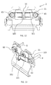
- FIG. 1 shows a load carrier foot 1 according to the present subject matter.
- the load carrier foot 1 comprises a mounting structure 2 for mounting the load carrier foot 1 on a vehicle.
- the load carrier foot 1 comprises a cover 4 for covering at least a part of the mounting structure 2.
- the cover 4 is locked to the load carrier foot 1 by means of a locking mechanism 11.
- the load carrier foot has two coupling elements 12 for establishing a fixed connection between a load carrying bar (not shown) and the load carrier foot 1.
- the locking mechanism 11 comprises a locking element which upon rotation in counter-clockwise direction unlocks the cover 4. In case the cover 4 is unlocked, it can be removed from the load carrier foot 1 in order to get access to the interior of the load carrier foot 1.
- FIG 2 the interior of a load carrier foot according to a first embodiment of the present subject matter is shown.
- the outer appearance of the load carrier foot corresponds to the load carrier foot shown in Figure 1 .
- the cover 4 is removed from the load carrier foot 1.
- other elements of the load carrier foot shown in Figure 1 have been omitted for the sake of clarity.
- the mounting structure 2 comprises a support 21 having an opening into which the tensioning screw 3 is inserted. Furthermore, the thread lock mechanism 5 is also supported on the support 21 as will become apparent in the following.
- the tensioning screw 3 is a hex cap screw with a hexagonal head 31 comprising a six-point star shaped pattern, more precisely a torx shape, as screw drive 32.
- a corresponding wrench By use of a corresponding wrench, it is possible to drive the tensioning screw 3 in the clockwise and counter-clockwise direction.
- the outer circumferential surface of the screw head 31 comprising the hexagonal shape functions as an engagement portion according to the present subject matter which is engageable with an engaging means of the thread lock mechanism 5.
- the thread lock mechanism comprises a swivel arm 5 having an engaging portion 51 as an engagement device at one end thereof and being pivotably coupled to the support 21 by means of a pivot pin 53 preferably integrally formed with the swivel arm 5.
- the pivot axis of the pivot pin 53 is in parallel to the longitudinal axis of the tensioning screw 3. Accordingly, it is possible to pivotably move the swivel arm 5 in a plane substantially perpendicular to the longitudinal axis of the tensioning screw 3.
- the swivel arm 5 further comprises an operating section 54 which can be grasped by a user for effecting a pivoting movement of the swivel arm 5.
- the operating section 54 is provided at the same end of the swivel arm 5 where the engagement device 51 of the swivel arm 5 is provided.
- Figure 2 shows the thread lock mechanism in an unlocking state. More precisely, as is shown in Figure 2 , the swivel arm 5 is in a position where the engaging portion 51 is removed from the hexagonal shaped screw head 31. Accordingly, the engaging portion 51 is disengaged from the screw head 31. Thus, a rotation of the tensioning screw 3 is possible. In order to engage the thread lock mechanism with the tensioning screw 3, the swivel arm 5 is moved in the clockwise direction in order to engage the engaging portion 51 with the screw head 31.
- Figure 3 shows a state in which the swivel arm 5 has been rotated in the clockwise direction into a position in which the engaging portion 51 is in engagement with the screw head 31 of the tensioning screw 3.
- a locking state of the thread lock mechanism is shown in Figure 3 .
- Figures 4 and 5 each show a sectional view of the thread lock mechanism 5 in a plane perpendicular to the pivot pin 53.
- the swivel arm 5 forming an engagement device of the load carrier foot comprises two arcuate walls 57, 58 radially extending from the pivot pin 53 and connected at their radial outer ends by means of a connecting wall 56. Furthermore, the swivel arm comprises a plate 52 connecting the lateral ends of the walls 57, 58 on one side. At a connecting portion at which the connecting wall 56 is connected with the arcuate wall 58, an engagement wall 55 is formed in a claw-like manner. In other words, the engagement wall extends from a radial outer portion of the arcuate wall 58 and forms a U-shape which is open on the side where the tensioning screw 3 is positioned.
- the engagement wall 55 comprises an engagement surface 55a which is arranged so as to face an engagement surface 56a of the connecting wall 56. More precisely, the engagement wall 55a and the engagement wall 56a are arranged in such a manner that a rotation of the swivel arm 5 in the clockwise direction arranges the walls 55a and 56a on opposite sides of the tensioning screw. The distance between the walls 55a and 56a is smaller than the maximum outer diameter of the engagement portion or screw head 31 of the tensioning screw 3. On a bottom surface 55b of the engagement wall 55, a protrusion 59 is formed functioning as a stop. In order to lock a rotation of the tensioning screw 3, the swivel arm 5 is rotated in the clockwise direction until the stop 59 abuts against the engagement portion of the tensioning screw 3.
- Figure 5 shows a state in which the rotation of the tensioning screw 3 is locked by the swivel arm 5.
- the engagement walls 55a and 56a are in contact with opposite flats of the hexagonally formed screw head 31 of the tensioning screw 3. Accordingly, a rotation of the tensioning screw 3 is locked.
- the opposite flats of the screw head 31 being in contact with the engagement walls 55a and 56a are substantially aligned with the engagement walls.
- an engagement of the engagement device 51 of the swivel arm 5 with the screw head 31 of the tensioning screw 3 is also possible in case the flats of the screw head 31 are not aligned with the engagement walls 55a and 56a.
- the walls 55 and 56 of the swivel arm 5 can be made of a flexible material. Accordingly, in case the flats of the screw head 31 are not aligned with the engagement walls 55a and 56a so that the distance between both walls is smaller than the effective engaging diameter of the screw head 31 being the maximum distance between the two points of the screw head 31 which will get into contact with the walls 55a and 56a. Due to the flexibility of the walls, the engaging walls 55a and 56a are resiliently pushed away from each other upon engaging the engaging portion 51 with the screw head 31 so that the engagement is possible.
- the resiliency of the engaging walls 55a and 56a can be achieved by forming the same by a corresponding material.
- the plate 52 and the walls 55a and 56a can be integrally formed by casting.
- the cover 4 is formed with a protrusion (not shown) which is in contact with the operating section 54 when the cover 4 is mounted.
- a protrusion not shown
- FIG 6 shows a load carrier foot according to a second embodiment of the present subject matter.
- the load carrier foot according to the second embodiment generally comprises the same appearance as the load carrier foot shown in Figure 1 when the cover is mounted thereon but differs from the load carrier foot according to the first embodiment in the construction of the thread lock mechanism. Furthermore, a different kind of tensioning screw is used in the second embodiment.
- Figures 6 and 7 show a mounting structure 2, a tensioning screw 6 and a thread lock mechanism comprising a locking element 7 of a load carrier foot 1 according to the second embodiment of the present subject matter in a front view and in a perspective view, respectively.
- Figure 8 shows a detailed perspective view of the locking element 7. The arrangement of the locking element 7 with respect to the tensioning screw 6 is shown in Figure 9 .
- the locking element 7 comprises engagement walls 72 and 73.
- the engagement walls 72, 73 are in contact with two flats 62 of a screw head 61 of a tensioning screw 6.
- the locking element 7 is movable with respect to the tensioning screw 6 so that the engagement walls 72 and 73 are also movable towards and away from the flats 62 of the tensioning screw 6.
- the tensioning screw 6 is arranged substantially horizontally and the locking element 7 and the engagement walls 72, 73 thereof rest on the flats 62 of the tensioning screw 6.
- the engagement walls 72, 73 ride over the flats and the corners of the screw head by performing an up and down movement in the vertical direction without exerting a significant force on the flats of the tensioning screw 6.
- the rotation of the tensioning screw 6 is unlocked as long as a movement of the locking element 7 is possible.
- the construction of the thread lock mechanism comprising the locking element 7 is shown in Figures 8 and 9 .
- the locking element 7 of the thread lock mechanism of the load carrier foot according to the second embodiment comprises a substantially flat base portion 71 and a crooked portion 74 connected to the base portion 71 at an angle.
- the base portion 71 comprises an opening 76 as well as two engagement walls 72 and 73.
- the opening 76 is a through-hole comprising a slit shape.
- the engagement walls 72 and 73 are arranged on opposite sides of the opening 76 and at an angle with respect to each other.
- the angle spanned between the engagement walls 72 and 73 is about 60° and corresponds to an angle spanned between two flats 62 of the tensioning screw 6.
- the engagement walls 72 and 73 extend substantially perpendicular to the base portion 71.
- the engagement walls 72, 73 are integrally formed with the base portion 71.
- the engagement walls 72 and 73 comprise a dimension still allowing to use the hex cap screw head of the tensioning screw 6 as a drive with which a wrench can be engaged for rotating the tensioning screw 6. More precisely, the engagement walls 72, 73 comprise a width which is smaller than the width of the flats 62 of the screw head 61 and comprise a height which is smaller than the height of the screw head 61.
- the crooked portion 74 comprises an abutment portion 75.
- the abutment portion 75 is formed so as to be engageable with a corresponding counter portion of the cover 4 in order to block the movement of the locking element 7.
- the tensioning screw 6 is inserted into the opening 76 of the base portion 71.
- the tensioning screw 6 comprises a stepped portion 63 comprising a height which substantially corresponds to the thickness of the base portion 71 and comprises an outer diameter which is slightly smaller than the width of the opening 76. Accordingly, the locking element 7 is movably guided by the stepped portion 73 of the tensioning screw 6. In case the movement of the locking element is blocked by placing the cover 4 in contact with the abutment portion 75, the engagement walls 72 and 73 are kept in contact with the flats 62 of the screw head 61. Accordingly, the rotation of the tensioning screw 6 is locked.
- the crooked portion 74 comprises a certain flexibility in order to compensate for a misalignment of the flats 62 with respect to the engagement walls 72 and 73.
- the locking element 7 is in a position in which it is offset in the vertical upward direction.
- the cover 4 is arranged on the load carrier foot 1 and contacts the abutment portion 75, the crooked portion 74 is resiliently bent and exerts a pushing force on the base portion 71 pushing the same in the vertical downward direction. Accordingly, the engagement walls 72 and 73 exert a pushing force on the corner portions 64 of the screw head 61.
- the tensioning screw 6 is able to rotate until the engagement walls 72 and 73 abut against the two flats 62.
- the engagement walls 72 and 73 rest on the flats and do not exert a significant force thereon.
- the tensioning screw is rotated due to self-rotation, the engagement walls 72 and 73 will exert a pushing force on the corner of the screw head. This pushing force counteracts the rotation of the tensioning screw.
- the load carrier foot according to the third embodiment comprises two tensioning screws 8.
- the thread lock mechanism of the load carrier foot according to the third embodiment comprises a clamp 9 which is pretensioned and exerts a pressing force on the engaging portion of the tensioning screws 8.
- the tensioning screw 8 according to the third embodiment comprises a screw head having a hexagonal shape and forming the engagement portion of the tensioning screw 8.
- the screw head furthermore comprises an internal drive 83.
- the clamp 9 has an arcuate shape and comprises two ends at which engagement device 93 are formed. More precisely, two engagement walls 92 and 94 are formed in each engagement device 93. Similar to the second embodiment, engagement walls 92 and 94 are arranged spaced from each other at an angle corresponding to the angle of two flats 82 of the screw head of the tensioning screws 8. As is shown in Figures 10 and 11 , the engagement walls 92 and 94 are arranged at the ends of the clamp 9. The engagement device 93 of the clamp 9 are connected to each other by an arcuate portion 91. In each engagement device 93, a slit-shaped opening 95 is formed extending in the longitudinal direction of clamp 9. The tensioning screw 8 is accommodated in the slit-shaped opening 95.
- the engagement device of the clamp 9 are moveable with respect to the tensioning screw 8. Furthermore, the arcuate portion 91 provides flexibility and pretensions the engagement portions 93 towards each other. Accordingly, the engagement walls 92 and 94 are pressed against the engagement portions, that is the screw heads of the tensioning screws 8. As is shown in Figure 11 , the engagement device 93 of the clamp 9 comprise a substantially flat base portion. The engagement walls 92 and 94 extend substantially perpendicular to the base portion. Furthermore, the clamp 9 is integrally formed of sheet metal by bending.
- a fourth embodiment of the present subject matter is described with reference to Figures 12 to 14 .
- the load carrier foot according to the fourth embodiment differs from the third embodiment in the construction of the thread lock mechanism.
- the thread lock mechanism according to the fourth embodiment is realized as a clamp 10 comprising two engaging portions 103 having engaging structures 104.
- the clamp 10 comprises an arcuate portion 101 and an operating portion 102.
- the clamp 9 is pretensioned such that the engagement device 93 exert a pushing force on the tensioning screw 8
- the engagement device 103 are not engaged with the engagement portion of the tensioning screws 8 in case the clamp 10 is not operated at the operating portion 102.
- the clamp 10 is not pretensioned.
- the operating portion 102 has to be pushed in a direction parallel to the longitudinal direction of the tensioning screws 8 and towards the support 21. In this case, the engaging portions 103 are moved in a direction substantially perpendicular to the longitudinal axis of the tensioning screws 8 thereby engaging with the engagement portion formed by the screw heads of the tensioning screw 8.
- the thread lock mechanism is in the form of a bracket 12 comprising a lower bracket portion 121, an upper bracket portion 124 and a connecting portion 125 connecting the lower bracket portion 121 with the upper bracket portion 124.
- the bracket 12 is integrally formed. More precisely, the different portions as described before are formed by bending a sheet metal in such a manner that the portions are arranged rectangular with respect to each other. Accordingly, the upper bracket portion 124 and the lower bracket portion 121 are arranged parallel to each other. As is also shown in Figure 15 , the lower bracket portion 121 comprises an opening 122 into which the tensioning screw 11 is insertable. Furthermore, the upper bracket portion 124 comprises a recess 123 for engagement with an engagement portion 111 of the tensioning screw 11. The recess 123 comprises multiple walls 126. The walls 126 are arranged at an angle corresponding to the angles at which the flats of the hexagonal engagement portion 111 are arranged.
- the brackets 12 can be designed such that no pushing force is exerted on the flats of the engagement portions 111 in case the flats are aligned with the walls 126. On the other hand, it is possible to form the bracket 12 such that in the latter mentioned case, a slight pushing force is exerted on the flats of the engagement portion 111. In either case, the rotation of the tensioning screw 11 is prevented by a contact of the engaging walls 126 with the flats of the engagement portion 111. In case the tensioning screw 11 is rotated, the upper bracket portion 124 is pushed away in a direction substantially perpendicular to the longitudinal axis of the tensioning screw 11 and, due to its resiliency, exerts a pushing force on the engagement portion 111 of the tensioning screw 11.
- the bracket 12 is designed to at least exert a pushing force on the engagement portion 111 in case the flats of the engagement portion 111 are not aligned with the engagement walls 126.
- Such pushing force is predetermined such that a self-rotation of the tensioning screw 11 is prevented.
- the pushing force is also predetermined such that the tensioning screw 11 can be rotated by using a wrench.
- FIGs 16 and 17 a load carrier foot according to a sixth embodiment of the present subject matter is shown.
- the general configuration of the load carrier foot is the same as that shown in Figure 1 and the load carrier foot according to the sixth embodiment differs from the one of Figure 1 in the construction of the thread lock mechanism. Therefore, for the sake of conciseness, only the thread lock mechanism of the load carrier foot according to the sixth embodiment is shown in Figures 16 and 17 .
- the thread lock mechanism in the load carrier foot mainly consists of a clamping element 13.
- the clamping element 13 comprises a base element having a rectangular shape in a plan view as shown in Figure 16 .
- the base element 131 comprises an opening (not shown) into which a tensioning screw 14 can be inserted.
- the clamping element has two bent sections and two curled protrusions 132 are formed on both sides of the screw head 141 of the tensioning screw 14.
- the curled portions 132 are arranged so as to abut the screw head 141 from both sides thereby clamping the same between them. Due to the curled configuration of the curled protrusions 132, the curled protrusions 132 comprise a certain flexibility. Accordingly, depending on the configuration, the curled protrusions 132 exert a force on the screw head 141 regardless of the rotational position of the tensioning screw 14 or is arranged such that no force is applied on the screw 14 in case the flats of the screw head 141 are aligned with a contact portion of the curled protrusions 132.
- the clamping element 13 is constructed such that at least in case flats of the screw head 141 are not aligned with the abutment portions of the curled protrusions 132 a force is applied on the screw head such that a force is applied on the screw head 141 counteracting the rotation of the tensioning screw 14.
- the curled protrusions 132 are constructed such that the force actable on the screw head 141 is predetermined such that a self-rotation of the tensioning screw 14 is prevented while a rotation of the tensioning screw 14 using a wrench engaged with a screw drive 142 enables the rotation of the tensioning screw 14. Accordingly, an easy and reliable thread lock mechanism is provided.
- the supporting element of the load carrier foot and the thread lock mechanism comprise a different construction.
- the protrusions are formed as straight walls 152 on a base element 151.
- the walls 152 are arranged such that when flats of the screw head 141 are positioned in parallel to the walls 152, a distance is provided between the walls 152 and the flats.
- the walls 152 can also be formed inclined towards the engagement portion of the tensioning screw 14, i.e. towards the screw head 141.
- an arrangement can be provided in which the free ends of the walls 152 are nearer to the flats than the root sections of the walls 152 at which the walls 152 are connected to the base element 131.
- the walls 152 can be leaned against the screw head 141 with their free ends.
- the distance between the free ends of the walls and the flats of the screw head 141 can be very small, i.e. close to zero, or it is even possible to arrange the wall such that no distance is provided between the free ends of the walls and the engagement portion. In the latter case, the free ends always contact the screw head (not shown).
- the flexibility of the walls 152 is adapted so that the walls 152 or at least their free ends are moved away from each other when the screw head 141 is turned.
- FIG 20 a further preferable embodiment of the present subject matter is shown.
- the construction of the load carrier foot according to this embodiment corresponds to the general construction of the load carrier foot shown in Figure 1 .
- the interior of the load carrier foot is similar to the construction shown in Figure 2 with the difference that the swivel arm 5 is omitted here.
- the engagement device is an elastic element 16 made of a plastic foam material, preferably polyurethane foam.
- the elastic element 16 is fixed on the inner side of cover 4 at a position at which it faces an axial end surface of the screw head 31 of the tensioning screw 3 when the cover 4 is mounted on the load carrier foot 1.
- the elastic element 16 is dimensioned so that it abuts against the end surface of the screw head when the cover 4 is mounted. More precisely, the elastic element 16 is dimensioned so that it is deformed by the screw head and exerts a pushing force on the end surface of the screw head of the tensioning screw. Consequently, a force is applied on the screw head counteracting a rotation of the screw 3.
Landscapes
- Engineering & Computer Science (AREA)
- General Engineering & Computer Science (AREA)
- Mechanical Engineering (AREA)
- Bolts, Nuts, And Washers (AREA)
- Seats For Vehicles (AREA)
Abstract
Description
- The present subject matter relates to a load carrier foot.
- Known load carrier feet typically comprise a mounting structure for mounting the load carrier feet on a vehicle and a tensioning screw. By rotating the tensioning screw, elements of the mounting structure are moved with respect to each other so as to fix the load carrier foot on the vehicle and/or to fix a load carrier bar on the load carrier foot. In order to ensure a secure fixation, it is necessary to prevent the tensioning screw from coming loose.
- The present subject matter relates to a load carrier foot.
- According to a first aspect of the present subject matter, the load carrier foot comprises a mounting structure for mounting the load carrier foot on a vehicle. The mounting structure can comprise a clamping mechanism for clamping the load carrier foot to a fixed roof rail or directly to the roof of the vehicle by gripping a body fold of the vehicle body.
- The load carrier further comprises a tightening means which is preferably a tensioning screw. The tightening means is adapted to actuate the clamping mechanism upon operation of the same. Thus, by operating the tightening means, it is possible to actuate the clamping mechanism so as to fix the load carrier foot on the vehicle roof. The mounting structure can comprise a through hole through which the tightening means, preferably the tensioning screw, is passed. That is, in case a tensioning screw is used, the lower end of the screw head can be brought into contact with the mounting structure exerting a pressing force against the same.
- Furthermore, the load carrier foot preferably comprises a locking mechanism for preventing the tightening means from coming loose. In case a tensioning screw is used as the tightening means, the locking mechanism can be a screw locking mechanism or thread lock mechanism for preventing the tensioning screw from coming loose.
- The tightening means which can be realized as tensioning screw can comprise an engagement portion formed in the outer periphery thereof. The locking mechanism - which can be the thread lock mechanism - preferably comprises an engagement device engageable with the engagement portion of the tightening means.
- Accordingly, the engagement portion and the engagement device can be correspondingly formed so as to be engageable with each other. In this connection, engageable with each other is to be understood as the engagement portion and the engagement device being formed such that a contact there between is either directly established upon engagement or both elements are formed and placed with respect to each other such that a contact can at least occur under certain circumstances, e.g. upon a slight rotation of the tensioning screw. The contact between both elements blocks a movement of the tightening means or at least makes a movement of the tightening means more difficult. That is, the engagement device is suitable to apply a predetermined force on the engagement portion counteracting a rotational movement of the tensioning screw.
- The movement of the tightening means can be prevented by providing a form-fit between the tightening means and the locking mechanism. On the other hand, the locking mechanism can be constructed to apply a friction force on the tightening means in order to prevent a movement thereof, either fully or to a certain extent. Accordingly, it is possible to provide a locking mechanism which, when engaged, enables a movement of the tightening means when a predetermined force is exceeded. Thus, in case a tensioning screw and a thread lock mechanism are used, the thread lock mechanism can be engaged with the tensioning screw such that a predetermined torque has to be exceeded in order to rotate the tensioning screw. In case the predetermined torque is not reached, the tensioning screw cannot rotate. Accordingly, an unintentional loosening of the tensioning screw, for example caused by vibrations, is prevented.
- It is further preferred that the engagement portion is formed in the outer periphery of the tensioning screw. Since the thread lock mechanism comprises an engagement device engageable with the engagement portion of the tensioning screw, the engagement device in this case contacts or is contactable with the outer periphery of the tensioning screw in the engagement portion. Accordingly, an engagement can be established by engaging the engagement device with the engagement portion from radially outside.
- Advantageously, the engagement portion is polygonally shaped, preferably hexagonally shaped. Accordingly, the engagement portion can comprise three or more flats and the engagement device can be constructed so as to get in contact with at least one flat or at least a portion of such a flat.
- Furthermore, the engagement device can be formed so as to at least partially comprise a shape corresponding to the outer periphery of the engagement portion. For example, in case the engagement portion is hexagonally shaped, it is possible to use an engagement device which contacts three adjacent flats of the engagement portion. While a polygonally shaped engagement portion is most preferable, it is also possible to provide an engagement portion comprising a different shape as long as it is possible to provide an engagement between the engagement device and the engagement portion for preventing a rotation of the tensioning screw. Accordingly, it is possible to use an engagement portion comprising an outer periphery which is continuously formed and is non-circular, elliptical for instance.
- Preferably, the engagement device comprises engagement walls contactable with the engagement portion and being moveable with respect to the engagement portion. The engagement walls can be formed by providing a protrusion on the engagement device. Furthermore, it is possible to provide a recess in the engagement device so as to form the engagement walls. Preferably, the engagement walls comprise flat surfaces.
- The width of the engagement walls can be formed so as to correspond to the width of a flat of the polygonal shape, that is, can have a width which is substantially identical to the width of one flat of the polygonal shape. It is furthermore possible to provide an engagement wall having a width which is smaller than the width of a flat of the polygonal shape. As regards the height of the engagement walls, the height can correspond to the dimension of the engagement portion in the longitudinal direction of the tensioning screw or can be smaller. The surface area of the engagement portion can be smaller than the surface area of one flat of the engagement portion. In case the height of the engagement wall is smaller than the dimension of the engagement device in the longitudinal direction, it is, for example, possible to keep the functionality of a screw head, that is to still enable a form-fit contact of a tool with the outer periphery of a screw head with the engagement wall arranged in place. The engagement walls can have an identical shape or can comprise different shapes.
- Instead of engagement walls, it is possible to provide curled stops, that is engagement device in which a sheet metal strip is rolled so that it comprises a spiral cross section. Such curled stops can be arranged so as to be or get in point or linear contact with the engagement portion depending on the shape of the same.
- Preferably, the engagement walls are resilient. A resiliency of the engagement walls can be achieved either by choosing a specific material and/or by choosing a certain construction. For example, an elastic material such as rubber can be used. On the other hand, it is possible to use a more rigid material and form thin protruding walls thereof which also comprise certain flexibility.
- According to a preferable embodiment of the present subject matter, the engagement walls are provided on opposite sides of the engagement portion. Accordingly, the engagement walls can be arranged to apply forces facing towards each other on the engagement portion. Such a construction provides a reliable force application on the engagement portion. Furthermore, since forces are applied from opposite sides, no bending moment is exerted on the tensioning screw.
- It is also possible to arrange two of the engagement walls at an angle. In this connection, the engagement walls can be arranged with a space there between or can be arranged adjacent to each other. Accordingly, the walls can be formed integrally forming a corner portion at a transition from one engagement wall to the other. Preferably, the angle corresponds to an angle spanned between two flats of the polygonally shaped engagement portion.
- According to a further embodiment of the present subject matter, the thread lock mechanism further comprises a swivel arm. The swivel arm can be mounted on the mounting structure pivotably about a pivot axis which is substantially parallel to the longitudinal axis of the tensioning screw. Preferably, the swivel arm is pivotable in a pivot plane perpendicular to the pivot axis. The engagement device can be provided on the swivel arm and can be engageable with the engagement portion by a pivoting motion of the swivel arm in the pivot plane.
- The swivel arm can be mounted to the mounting structure at one end thereof and the engagement device can be provided at the other end thereof. Furthermore, the swivel arm can have an elongate shape and can comprise a straight or curved shape. Preferably, the swivel arm is constructed such that it is pivotable in the pivot plane only. Thus, the swivel arm can be constructed and can be mounted in such a way that it is substantially not moveable in a direction perpendicular to the pivot plane. In this connection, the engagement device is constructed so as to be able to accommodate the engagement portion therein by pivotably moving the swivel arm. That is, in the engagement portion, an opening can be formed in the leading end of the swivel arm.
- The swivel arm can further comprise an actuating portion which is suitably formed to be grasped by a user. Therefore, the user can move the swivel arm so as to engage the engagement device by means of the engagement portion. In order to lock the movement of the swivel arm, the swivel arm can be formed so as to have an abutment portion contactable with a cover of the load carrier foot. In other words, the cover of the load carrier foot can be formed with a stop either completely blocking the movement of the swivel arm or allowing a movement of the swivel arm to a certain extent while the thread locking function remains effective. Preferably, the stop is formed so as to be contactable with the actuating portion. The stop can be a protrusion extending from a wall of the cover.
- Preferably, the engagement device is formed as a claw-like portion adapted to partially surround the engagement portion. The claw-like formed engagement device can comprise at least two contact areas contactable with the outer surface of the engagement portion. Preferably, two of the at least two contact areas are provided on opposite sides of the engagement portion. Preferably, the engagement device comprises an opening which is open in the engagement direction.
- Advantageously, the swivel arm comprises a plate extending substantially in the pivot plane and walls extending substantially perpendicular to the plate. The engagement device can be formed by suitably arranging the walls. For example, it is possible to arrange the walls with a distance between the same so as to form a space in which the engagement portion can be accommodated. The walls can be integrally formed with the plate. Furthermore, it is possible to use different materials for the plate and the walls. More precisely, the rigidity of the material used for the plate can be higher than the rigidity used for the walls. With such an arrangement, it is possible to provide walls having a specific flexibility. Consequently, the walls used for engaging the engagement portion are able to flex at their free ends. Hence, the engagement device can be constructed such that the space provided between the walls used for engaging the engagement portion can be smaller than the maximum outer diameter of the engagement portion.
- According to a preferable construction, the plate is provided over the entire range of the swivel arm. In this construction, the walls forming the engagement device protrude from the plate. According to another preferable construction, the plate does not range over the entire range of the swivel arm. According to this construction, it is possible to provide one wall protruding from the plate in a perpendicular direction and to provide another wall protruding radially and curved from the radial outer end of the plate. Accordingly, it is possible to use a construction in which the plate covers the tensioning screw in case the engagement device is engaged with the engagement portion or to use a construction in which the claw-like portion protrudes from a radial end of the plate so that a hook is formed on the end of the swivel arm which is engageable with the engagement portion.
- Preferably, the engagement device is lockably moveable in a direction perpendicular to the longitudinal axis of the tensioning screw. In this connection, lockably moveable means that the engagement device is moveable as long as the movement is not blocked by a suitable blocking means. The movement can be blocked by means of an additional element. For example, the load carrier foot can comprise a cover for covering the interior of the load carrier foot and the cover can be adapted to block the movement of the engagement device. For that purpose, the cover can comprise a protrusion getting near or contacting the engagement device upon mounting the same. Accordingly, a construction is achieved in which the engagement device is moveable in a direction perpendicular to the longitudinal axis of the tensioning screw as long as the cover is not provided on the load carrier foot and in which the movement of the engagement device is blocked in case the cover is provided on the load carrier foot.
- The engagement device can comprise a base member and two walls protruding therefrom. Advantageously, both of the two walls extend substantially perpendicular to base member. The base member and the walls are guided so as to be moveable perpendicular to the longitudinal axis of the tensioning screw and are freely moveable as long as no cover is provided on the load carrier foot. For guiding purposes, the base member can comprise an opening through which the tensioning element, the tensioning screw for instance, is passed. The opening can comprises a width slightly larger than the outer diameter of a tensioning screw portion. With such a construction, the movability of the engagement device with respect to the tensioning screw is guaranteed. Furthermore, the opening comprises a length enabling the engagement device to move relative to the tensioning screw such that the two walls can move away from the engagement portion to an extent that the two walls do not block the rotation of the tensioning screw.
- According to a preferable arrangement, the tensioning screw comprises a hexagonal outer shape and the walls of the engagement device are able to get in contact with two of the flats of the hexagonal shape. In case no cover is provided on the load carrier foot, the engagement device is pushed away from the tensioning screw in case the same is rotated. In other words, the walls of the engagement device ride over the flats and edges of the hexagonal outer shape of the screw head. Accordingly, the tensioning screw is rotatable in case the cover is not provided on the load carrier foot. On the contrary, in case the cover is provided on the load carrier foot, the movement of the engagement device is blocked so that the rotation of the tensioning screw cannot or at least cannot substantially effect a movement of the walls in the direction perpendicular to the longitudinal axis of the tensioning screw. Consequently, the walls exert a pushing force on or get in contact with the outer periphery of the tensioning screw and therefore prevent a rotation of the same.
- According to a preferable construction, the engagement device is prestressed so as to continuously apply a force on the engagement portion in a direction perpendicular to the longitudinal axis of the tensioning screw. For example, a spring element can be provided so as to prestress the engagement device or the engagement device can be constructed so as to comprise such a spring element function. The thread lock mechanism can comprise a blade spring and the engagement device can be provided on an end of the blade spring. According to this construction, the engagement device is moveable in the longitudinal direction of the blade spring against the blade spring force. Depending on the construction, the engagement device exerts a tensile or a pushing force on the engagement portion.
- The use of an engagement device comprising a blade spring is particularly advantageous for an arrangement in which two tensioning screws are used in the load carrier foot. In such a construction, the engagement device can be provided on each end of the blade spring, one for each tensioning screw. Each of the two engagement device can comprise an opening for passing a tensioning screw there through. The opening has a width slightly larger than a corresponding supporting portion of the tensioning screw and a length enabling a movement of each engagement device relative to the tensioning screw so that the walls can be moved relative to the tensioning screws. As already described above, the blade spring can be prestressed. In other words, the blade spring can be configured such that the walls of the engagement device are pushed against the engagement portion either by a tensile or a pushing force. It is, however, possible to use a construction in which a blade spring is used which is not prestressed. In this case, for effecting the locking action, it is necessary to push the blade spring so that the engaging means is engaged with the engagement portion of the tensioning screw.
- According to a further embodiment of the present subject matter, the engagement walls are arranged parallel to and spaced from each other. Accordingly, the engagement walls can be arranged on opposite sides of the engagement portion. Preferably, the engagement portion comprises an even number of flats and the distance between the two engagement surfaces of the engagement walls is smaller than the maximum outer diameter of the engagement portion. Accordingly, the engagement surfaces can be arranged such that in case the engagement portion comprising an even number of flats is arranged such that the flats are in parallel to the engagement surfaces, a small gap is arranged between the engagement walls and the flats or the engagement surfaces contact the flats.
- According to a further preferable embodiment of the present subject matter, the engagement device comprises an opening accommodating the tensioning screw. Accordingly, the engagement device can have a construction which allows the tensioning screw to pass the same. For example, the engagement device can comprise a through hole through which the tensioning screw can be passed. In case the engagement device shall be moveable to a direction perpendicular to the longitudinal axis of the tensioning screw, the through hole can comprise an elongate shape. Thus, when the tensioning screw is inserted in the elongate through hole, the engagement device is moveable to a certain extent.
- Preferably, the engagement device is adapted to apply a predetermined torque on the engaging portion wherein the predetermined torque counteracts a loosening torque of the tensioning screw.
- According to a further embodiment of the present subject matter, the engagement device can be integrally formed from sheet metal by bending, and the the walls can be formed straight or curled. Furthermore, in case the walls are formed straight, the walls can be formed inclined towards the engagement portion of the tensioning screw. Accordingly, an arrangement can be used in which the free end of the wall is nearer to the engagement portion than the root section of the wall. The walls can be leaned against the engagement portion, e.g. the screw head of the tensioning screw, with their free ends. In this configuration, the distance between the free end of the walls and the flats of the screw head can be provided close to zero or it is possible to even arrange the wall such that no distance is provided between the free ends of the walls and the engagement portion. In the latter case, the free ends always contact the screw head. In this connection, the flexibility of the wall is adapted to this configuration in that the free ends are pushable in a direction substantially perpendicular to the longitudinal axis of the tensioning screw when the screw head is turned.
- According to a further preferable embodiment, the engagement device is an elastic element, preferably made of plastic foam material, adapted to be pushed against the engagement portion of the tensioning screw for applying a counterforce for preventing the tensioning screw from coming loose. For example, the elastic element can be fixed on the inner side of a cover for covering the interior of the load carrier foot. By this, it is possible to arrange the elastic element so that in case the cover is mounted on the load carrier foot, the elastic element is pushed against the engagement portion of the tensioning screw. By pushing the elastic element against the engagement portion of the tensioning screw the elastic element is deformed such that the engagement portion of the tensioning screw is partially surrounded by the same leading to a connection comprising both a friction fit and a form fit component. For example, in case the engagement portion of the tensioning screw is provided in the form of a hexagonal screw head and the elastic element is pushed against the screw head, an impression having a hexagonal shape is formed in the elastic element wherein the elastic element partially extends along the flats of the screw head in the longitudinal direction of the tensioning screw. Consequently, a force transmitting connection is achieved in which the friction fit component results from the cooperation between the screw head surface and the surface of the elastic element and the form fit component results from the reproduction of the hexagonal shape of the screw head in the elastic element engaging with the flats of the screw head.
-
- Figure 1
- shows a perspective view of a load carrier according to the present subject matter;
- Figure 2
- shows a mounting structure and a thread lock mechanism of a load carrier foot according to a first embodiment of the present subject matter;
- Figure 3
- shows the thread lock mechanism of the load carrier foot according to the first embodiment in a locking state;
- Figure 4
- shows a sectional view showing the construction of the thread lock mechanism of the load carrier foot according to the first embodiment in detail in an unlocking state;
- Figure 5
- shows a sectional view of the thread lock mechanism of the load carrier foot according to the first embodiment in a locking state;
- Figure 6
- shows a load carrier foot according to a second embodiment of the present subject matter;
- Figure 7
- shows a perspective view of the thread lock mechanism of the load carrier foot according to the second embodiment of the present subject matter shown in
Figure 6 ; - Figure 8
- shows an engagement device of the thread lock mechanism of the load carrier foot according to the second embodiment of the present subject matter;
- Figure 9
- shows the engagement device according to
Figure 8 in combination with a tensioning screw; - Figure 10
- shows a third embodiment of a load carrier foot according to the present subject matter;
- Figure 11
- shows an engagement device of the load carrier foot according to the third embodiment of the present subject matter together with two tensioning screws;
- Figure 12
- shows a thread lock mechanism of a load carrier foot according to a fourth embodiment of the present subject matter;
- Figure 13
- shows a perspective view of the thread lock mechanism shown in
Figure 12 ; - Figure 14
- shows a plan view of an engagement device of the thread lock mechanism shown in
Figures 12 and 13 ; - Figure 15
- shows an engagement device of a thread lock mechanism of a load carrier foot according to a fifth embodiment of the present subject matter;
- Figure 16
- shows a plan view of an engagement device of a thread lock mechanism of a load carrier foot according to a sixth embodiment of the present subject matter;
- Figure 17
- shows a side view of the engagement portion shown in
Figure 16 ; - Figure 18
- shows a perspective view of the interior of a load carrier foot according to a modification of the sixth embodiment of the present subject matter;
- Figure 19
- shows a perspective side view of the thread lock mechanism according to the modification shown in
Figure 18 ; and - Figure 20
- shows a thread lock mechanism according to a seventh embodiment of the present subject matter.
- In the following, embodiments of the present subject matter will be explained based on the drawings. It is noticed that the drawings show specific embodiments as explained below and further alternative modifications as specified in the description are at least in part not illustrated therein. Furthermore, same reference signs used in the Figures denote same components.
-
Figure 1 shows aload carrier foot 1 according to the present subject matter. Theload carrier foot 1 comprises a mountingstructure 2 for mounting theload carrier foot 1 on a vehicle. - Furthermore, the
load carrier foot 1 comprises acover 4 for covering at least a part of the mountingstructure 2. Thecover 4 is locked to theload carrier foot 1 by means of alocking mechanism 11. Moreover, as is also shown inFigure 1 , the load carrier foot has twocoupling elements 12 for establishing a fixed connection between a load carrying bar (not shown) and theload carrier foot 1. Thelocking mechanism 11 comprises a locking element which upon rotation in counter-clockwise direction unlocks thecover 4. In case thecover 4 is unlocked, it can be removed from theload carrier foot 1 in order to get access to the interior of theload carrier foot 1. - In
Figure 2 , the interior of a load carrier foot according to a first embodiment of the present subject matter is shown. The outer appearance of the load carrier foot corresponds to the load carrier foot shown inFigure 1 . InFigure 2 , thecover 4 is removed from theload carrier foot 1. Furthermore, other elements of the load carrier foot shown inFigure 1 have been omitted for the sake of clarity. - As is shown in
Figure 2 , removing thecover 4 reveals parts of the mountingstructure 2, atensioning screw 3 and athread lock mechanism 5 for preventing the tensioning screw from coming loose. - The mounting
structure 2 comprises asupport 21 having an opening into which thetensioning screw 3 is inserted. Furthermore, thethread lock mechanism 5 is also supported on thesupport 21 as will become apparent in the following. - In the load carrier foot according to the first embodiment, the
tensioning screw 3 is a hex cap screw with ahexagonal head 31 comprising a six-point star shaped pattern, more precisely a torx shape, asscrew drive 32. By use of a corresponding wrench, it is possible to drive thetensioning screw 3 in the clockwise and counter-clockwise direction. The outer circumferential surface of thescrew head 31 comprising the hexagonal shape functions as an engagement portion according to the present subject matter which is engageable with an engaging means of thethread lock mechanism 5. - According to the present first embodiment, the thread lock mechanism comprises a
swivel arm 5 having an engagingportion 51 as an engagement device at one end thereof and being pivotably coupled to thesupport 21 by means of apivot pin 53 preferably integrally formed with theswivel arm 5. As is shown inFigure 2 , the pivot axis of thepivot pin 53 is in parallel to the longitudinal axis of thetensioning screw 3. Accordingly, it is possible to pivotably move theswivel arm 5 in a plane substantially perpendicular to the longitudinal axis of thetensioning screw 3. - The
swivel arm 5 further comprises anoperating section 54 which can be grasped by a user for effecting a pivoting movement of theswivel arm 5. According to the embodiment, the operatingsection 54 is provided at the same end of theswivel arm 5 where theengagement device 51 of theswivel arm 5 is provided. -
Figure 2 shows the thread lock mechanism in an unlocking state. More precisely, as is shown inFigure 2 , theswivel arm 5 is in a position where the engagingportion 51 is removed from the hexagonal shapedscrew head 31. Accordingly, the engagingportion 51 is disengaged from thescrew head 31. Thus, a rotation of thetensioning screw 3 is possible. In order to engage the thread lock mechanism with thetensioning screw 3, theswivel arm 5 is moved in the clockwise direction in order to engage the engagingportion 51 with thescrew head 31. -
Figure 3 shows a state in which theswivel arm 5 has been rotated in the clockwise direction into a position in which the engagingportion 51 is in engagement with thescrew head 31 of thetensioning screw 3. In other words, a locking state of the thread lock mechanism is shown inFigure 3 . - In the following, the construction of the thread lock mechanism of the load carrier foot according to first embodiment of the present subject matter will be described in detail with reference to
Figures 4 and5 .Figures 4 and5 each show a sectional view of thethread lock mechanism 5 in a plane perpendicular to thepivot pin 53. - The
swivel arm 5 forming an engagement device of the load carrier foot according to the first embodiment, comprises twoarcuate walls pivot pin 53 and connected at their radial outer ends by means of a connectingwall 56. Furthermore, the swivel arm comprises aplate 52 connecting the lateral ends of thewalls wall 56 is connected with thearcuate wall 58, anengagement wall 55 is formed in a claw-like manner. In other words, the engagement wall extends from a radial outer portion of thearcuate wall 58 and forms a U-shape which is open on the side where thetensioning screw 3 is positioned. - The
engagement wall 55 comprises anengagement surface 55a which is arranged so as to face anengagement surface 56a of the connectingwall 56. More precisely, theengagement wall 55a and theengagement wall 56a are arranged in such a manner that a rotation of theswivel arm 5 in the clockwise direction arranges thewalls walls head 31 of thetensioning screw 3. On abottom surface 55b of theengagement wall 55, aprotrusion 59 is formed functioning as a stop. In order to lock a rotation of thetensioning screw 3, theswivel arm 5 is rotated in the clockwise direction until thestop 59 abuts against the engagement portion of thetensioning screw 3. -
Figure 5 shows a state in which the rotation of thetensioning screw 3 is locked by theswivel arm 5. Theengagement walls screw head 31 of thetensioning screw 3. Accordingly, a rotation of thetensioning screw 3 is locked. In the arrangement shown inFigure 5 , the opposite flats of thescrew head 31 being in contact with theengagement walls engagement device 51 of theswivel arm 5 with thescrew head 31 of thetensioning screw 3 is also possible in case the flats of thescrew head 31 are not aligned with theengagement walls - In order to provide a secure engagement with the engagement portion of the
tensioning screw 3, thewalls swivel arm 5 can be made of a flexible material. Accordingly, in case the flats of thescrew head 31 are not aligned with theengagement walls screw head 31 being the maximum distance between the two points of thescrew head 31 which will get into contact with thewalls walls portion 51 with thescrew head 31 so that the engagement is possible. Due to the resiliency, a force is exerted on the screw head by the engagingwalls walls screw head 31, the force exerted on the flats of thescrew head 31 by the engagingwalls walls screw head 31 counteracting such a rotation. - The resiliency of the
engaging walls swivel arm 5 more rigid, it is possible to form theplate 52 with a material which is more rigid than the material of which theengaging walls plate 52 and thewalls - In order to securely prevent the
swivel arm 5 from rotating in a disengaging direction, thecover 4 is formed with a protrusion (not shown) which is in contact with the operatingsection 54 when thecover 4 is mounted. Thus, the rotation of theswivel arm 5 can be securely prevented during use of the load carrier foot. -
Figure 6 shows a load carrier foot according to a second embodiment of the present subject matter. The load carrier foot according to the second embodiment generally comprises the same appearance as the load carrier foot shown inFigure 1 when the cover is mounted thereon but differs from the load carrier foot according to the first embodiment in the construction of the thread lock mechanism. Furthermore, a different kind of tensioning screw is used in the second embodiment. - A construction of the thread lock mechanism according to the second embodiment will be described in detail with reference to
Figures 6 to 9 in the following. -
Figures 6 and7 show a mountingstructure 2, atensioning screw 6 and a thread lock mechanism comprising alocking element 7 of aload carrier foot 1 according to the second embodiment of the present subject matter in a front view and in a perspective view, respectively.Figure 8 shows a detailed perspective view of thelocking element 7. The arrangement of thelocking element 7 with respect to thetensioning screw 6 is shown inFigure 9 . - As is shown in these Figures, the locking
element 7 comprisesengagement walls engagement walls flats 62 of ascrew head 61 of atensioning screw 6. The lockingelement 7 is movable with respect to thetensioning screw 6 so that theengagement walls flats 62 of thetensioning screw 6. - According to the arrangement shown in
Figure 6 , thetensioning screw 6 is arranged substantially horizontally and thelocking element 7 and theengagement walls flats 62 of thetensioning screw 6. Upon rotation of thetensioning screw 6, theengagement walls tensioning screw 6. In other words, since it is possible to push theengagement walls tensioning screw 6 is unlocked as long as a movement of thelocking element 7 is possible. - The construction of the thread lock mechanism comprising the
locking element 7 is shown inFigures 8 and9 . The lockingelement 7 of the thread lock mechanism of the load carrier foot according to the second embodiment comprises a substantiallyflat base portion 71 and acrooked portion 74 connected to thebase portion 71 at an angle. Thebase portion 71 comprises anopening 76 as well as twoengagement walls opening 76 is a through-hole comprising a slit shape. At one end of the slit-shapedopening 76, theengagement walls opening 76 and at an angle with respect to each other. - According to the embodiment, the angle spanned between the
engagement walls flats 62 of thetensioning screw 6. As is also shown inFigure 8 , theengagement walls base portion 71. Furthermore, theengagement walls base portion 71. As is further shown inFigure 9 , theengagement walls tensioning screw 6 as a drive with which a wrench can be engaged for rotating thetensioning screw 6. More precisely, theengagement walls flats 62 of thescrew head 61 and comprise a height which is smaller than the height of thescrew head 61. - The
crooked portion 74 comprises anabutment portion 75. Theabutment portion 75 is formed so as to be engageable with a corresponding counter portion of thecover 4 in order to block the movement of thelocking element 7. - The functioning of the
locking element 7 is described with reference toFigure 9 . As is shown, thetensioning screw 6 is inserted into theopening 76 of thebase portion 71. Thetensioning screw 6 comprises a steppedportion 63 comprising a height which substantially corresponds to the thickness of thebase portion 71 and comprises an outer diameter which is slightly smaller than the width of theopening 76. Accordingly, the lockingelement 7 is movably guided by the steppedportion 73 of thetensioning screw 6. In case the movement of the locking element is blocked by placing thecover 4 in contact with theabutment portion 75, theengagement walls flats 62 of thescrew head 61. Accordingly, the rotation of thetensioning screw 6 is locked. - The
crooked portion 74 comprises a certain flexibility in order to compensate for a misalignment of theflats 62 with respect to theengagement walls screw head 61 is in a position in which theengagement walls contact corner portions 64 of thescrew head 61, the lockingelement 7 is in a position in which it is offset in the vertical upward direction. In case thecover 4 is arranged on theload carrier foot 1 and contacts theabutment portion 75, thecrooked portion 74 is resiliently bent and exerts a pushing force on thebase portion 71 pushing the same in the vertical downward direction. Accordingly, theengagement walls corner portions 64 of thescrew head 61. Consequently, thetensioning screw 6 is able to rotate until theengagement walls flats 62. When theflats 62 are aligned with theengagement walls engagement walls engagement walls - In the following, the construction of a load carrier foot according to a third embodiment of the present subject matter will be described in detail with reference to
Figures 10 and11 . Contrary to the first and second embodiments described above, the load carrier foot according to the third embodiment comprises two tensioning screws 8. - The thread lock mechanism of the load carrier foot according to the third embodiment comprises a
clamp 9 which is pretensioned and exerts a pressing force on the engaging portion of the tensioning screws 8. Similar to the tensioning screws according to the first and second embodiment, thetensioning screw 8 according to the third embodiment comprises a screw head having a hexagonal shape and forming the engagement portion of thetensioning screw 8. The screw head furthermore comprises aninternal drive 83. - The
clamp 9 has an arcuate shape and comprises two ends at whichengagement device 93 are formed. More precisely, twoengagement walls 92 and 94 are formed in eachengagement device 93. Similar to the second embodiment,engagement walls 92 and 94 are arranged spaced from each other at an angle corresponding to the angle of twoflats 82 of the screw head of the tensioning screws 8. As is shown inFigures 10 and11 , theengagement walls 92 and 94 are arranged at the ends of theclamp 9. Theengagement device 93 of theclamp 9 are connected to each other by anarcuate portion 91. In eachengagement device 93, a slit-shapedopening 95 is formed extending in the longitudinal direction ofclamp 9. Thetensioning screw 8 is accommodated in the slit-shapedopening 95. The engagement device of theclamp 9 are moveable with respect to thetensioning screw 8. Furthermore, thearcuate portion 91 provides flexibility and pretensions theengagement portions 93 towards each other. Accordingly, theengagement walls 92 and 94 are pressed against the engagement portions, that is the screw heads of the tensioning screws 8. As is shown inFigure 11 , theengagement device 93 of theclamp 9 comprise a substantially flat base portion. Theengagement walls 92 and 94 extend substantially perpendicular to the base portion. Furthermore, theclamp 9 is integrally formed of sheet metal by bending. - A fourth embodiment of the present subject matter is described with reference to
Figures 12 to 14 . The load carrier foot according to the fourth embodiment differs from the third embodiment in the construction of the thread lock mechanism. - The thread lock mechanism according to the fourth embodiment is realized as a
clamp 10 comprising twoengaging portions 103 having engagingstructures 104. Theclamp 10 comprises anarcuate portion 101 and an operatingportion 102. However, contrary to the third embodiment in which theclamp 9 is pretensioned such that theengagement device 93 exert a pushing force on thetensioning screw 8, theengagement device 103 are not engaged with the engagement portion of the tensioning screws 8 in case theclamp 10 is not operated at the operatingportion 102. In other words, theclamp 10 is not pretensioned. In order to engage the engagingportions 103 with the engagement portions of the tensioning screws 8, the operatingportion 102 has to be pushed in a direction parallel to the longitudinal direction of the tensioning screws 8 and towards thesupport 21. In this case, the engagingportions 103 are moved in a direction substantially perpendicular to the longitudinal axis of the tensioning screws 8 thereby engaging with the engagement portion formed by the screw heads of thetensioning screw 8. - In
Figure 15 , a thread lock mechanism of a load carrier foot according to a fifth embodiment of the present subject matter is described. The thread lock mechanism is in the form of abracket 12 comprising alower bracket portion 121, anupper bracket portion 124 and a connectingportion 125 connecting thelower bracket portion 121 with theupper bracket portion 124. - As is obvious from
Figure 15 , in the embodiment, thebracket 12 is integrally formed. More precisely, the different portions as described before are formed by bending a sheet metal in such a manner that the portions are arranged rectangular with respect to each other. Accordingly, theupper bracket portion 124 and thelower bracket portion 121 are arranged parallel to each other. As is also shown inFigure 15 , thelower bracket portion 121 comprises anopening 122 into which thetensioning screw 11 is insertable. Furthermore, theupper bracket portion 124 comprises arecess 123 for engagement with anengagement portion 111 of thetensioning screw 11. Therecess 123 comprisesmultiple walls 126. Thewalls 126 are arranged at an angle corresponding to the angles at which the flats of thehexagonal engagement portion 111 are arranged. Thebrackets 12 can be designed such that no pushing force is exerted on the flats of theengagement portions 111 in case the flats are aligned with thewalls 126. On the other hand, it is possible to form thebracket 12 such that in the latter mentioned case, a slight pushing force is exerted on the flats of theengagement portion 111. In either case, the rotation of thetensioning screw 11 is prevented by a contact of theengaging walls 126 with the flats of theengagement portion 111. In case thetensioning screw 11 is rotated, theupper bracket portion 124 is pushed away in a direction substantially perpendicular to the longitudinal axis of thetensioning screw 11 and, due to its resiliency, exerts a pushing force on theengagement portion 111 of thetensioning screw 11. By this, a force counteracting the rotation of thescrew 11 is exerted on theengagement portion 111. According to the embodiment, thebracket 12 is designed to at least exert a pushing force on theengagement portion 111 in case the flats of theengagement portion 111 are not aligned with theengagement walls 126. Such pushing force is predetermined such that a self-rotation of thetensioning screw 11 is prevented. On the other hand, the pushing force is also predetermined such that thetensioning screw 11 can be rotated by using a wrench. - In
Figures 16 and 17 , a load carrier foot according to a sixth embodiment of the present subject matter is shown. The general configuration of the load carrier foot is the same as that shown inFigure 1 and the load carrier foot according to the sixth embodiment differs from the one ofFigure 1 in the construction of the thread lock mechanism. Therefore, for the sake of conciseness, only the thread lock mechanism of the load carrier foot according to the sixth embodiment is shown inFigures 16 and 17 . - The thread lock mechanism in the load carrier foot according to the sixth embodiment of the present subject matter mainly consists of a clamping
element 13. The clampingelement 13 comprises a base element having a rectangular shape in a plan view as shown inFigure 16 . Thebase element 131 comprises an opening (not shown) into which atensioning screw 14 can be inserted. As is shown inFigure 17 , the clamping element has two bent sections and two curledprotrusions 132 are formed on both sides of thescrew head 141 of thetensioning screw 14. - The curled
portions 132 are arranged so as to abut thescrew head 141 from both sides thereby clamping the same between them. Due to the curled configuration of the curledprotrusions 132, the curledprotrusions 132 comprise a certain flexibility. Accordingly, depending on the configuration, the curledprotrusions 132 exert a force on thescrew head 141 regardless of the rotational position of thetensioning screw 14 or is arranged such that no force is applied on thescrew 14 in case the flats of thescrew head 141 are aligned with a contact portion of the curledprotrusions 132. - The clamping
element 13 is constructed such that at least in case flats of thescrew head 141 are not aligned with the abutment portions of the curled protrusions 132 a force is applied on the screw head such that a force is applied on thescrew head 141 counteracting the rotation of thetensioning screw 14. According to the embodiment, the curledprotrusions 132 are constructed such that the force actable on thescrew head 141 is predetermined such that a self-rotation of thetensioning screw 14 is prevented while a rotation of thetensioning screw 14 using a wrench engaged with ascrew drive 142 enables the rotation of thetensioning screw 14. Accordingly, an easy and reliable thread lock mechanism is provided. - A modification of the sixth embodiment is described with reference to
Figures 18 and 19 . According to the modification, the supporting element of the load carrier foot and the thread lock mechanism comprise a different construction. Instead of the curledprotrusions 132, the protrusions are formed asstraight walls 152 on abase element 151. Furthermore, contrary to the configuration with the curledprotrusions 132, thewalls 152 are arranged such that when flats of thescrew head 141 are positioned in parallel to thewalls 152, a distance is provided between thewalls 152 and the flats. Thewalls 152 can also be formed inclined towards the engagement portion of thetensioning screw 14, i.e. towards thescrew head 141. Accordingly, an arrangement can be provided in which the free ends of thewalls 152 are nearer to the flats than the root sections of thewalls 152 at which thewalls 152 are connected to thebase element 131. Thewalls 152 can be leaned against thescrew head 141 with their free ends. In this configuration, the distance between the free ends of the walls and the flats of thescrew head 141 can be very small, i.e. close to zero, or it is even possible to arrange the wall such that no distance is provided between the free ends of the walls and the engagement portion. In the latter case, the free ends always contact the screw head (not shown). In either case, the flexibility of thewalls 152 is adapted so that thewalls 152 or at least their free ends are moved away from each other when thescrew head 141 is turned. - In
Figure 20 , a further preferable embodiment of the present subject matter is shown. The construction of the load carrier foot according to this embodiment corresponds to the general construction of the load carrier foot shown inFigure 1 . Furthermore, the interior of the load carrier foot is similar to the construction shown inFigure 2 with the difference that theswivel arm 5 is omitted here. - According to the embodiment, the engagement device is an
elastic element 16 made of a plastic foam material, preferably polyurethane foam. Theelastic element 16 is fixed on the inner side ofcover 4 at a position at which it faces an axial end surface of thescrew head 31 of thetensioning screw 3 when thecover 4 is mounted on theload carrier foot 1. Theelastic element 16 is dimensioned so that it abuts against the end surface of the screw head when thecover 4 is mounted. More precisely, theelastic element 16 is dimensioned so that it is deformed by the screw head and exerts a pushing force on the end surface of the screw head of the tensioning screw. Consequently, a force is applied on the screw head counteracting a rotation of thescrew 3.
Claims (15)
- Load carrier foot (1) having a mounting structure (2) for mounting the load carrier foot on a vehicle, a tensioning screw (3; 6; 8; 11; 14) and a thread lock mechanism (5; 7; 9; 10; 12; 13; 15; 16) for preventing the tensioning screw (3; 6; 8; 11; 14) from coming loose, wherein the tensioning screw (3; 6; 8; 11; 14) comprises an engagement portion (31; 61; 82; 111; 141) formed in the outer periphery thereof and wherein the thread lock mechanism (5; 7; 9; 10; 12; 13; 15; 16) comprises an engagement device (51; 71; 93; 103; 123; 132; 152) engageable with the engagement portion (31; 61; 82; 111; 141) of the tensioning screw (3; 6; 8; 11; 14).
- Load carrier foot according to claim 1, wherein the engagement portion (31; 61; 82; 111; 141) is polygonally shaped, preferably hexagonally shaped.
- Load carrier foot according to one of claims 1 and 2, wherein the engagement device (51; 71; 93; 103; 123; 132; 152) comprises engagement walls (55a, 56a; 72, 73; 92; 104; 126; 132; 152) contactable with the engagement portion (31; 61; 82; 111; 141) and being movable with respect to the engagement portion (31; 61; 82; 111; 141).
- Load carrier foot according to claim 3, wherein the engagement walls (55a, 56a; 72, 73; 92; 104; 126; 132; 152) are resilient.
- Load carrier foot according to one of claims 3 or 4, wherein the engagement walls (55a, 56a; 132; 152) are provided on opposite sides of the engagement portion (31; 141).
- Load carrier foot according to one of claims 3 or 4, wherein two of the engagement walls (72, 73; 92; 104; 126) are arranged at an angle.
- Load carrier foot according to one of the preceding claims, the thread lock mechanism further comprising a swivel arm (5), the swivel arm (5) being mounted on the mounting structure (2) pivotably about a pivot axis substantially parallel to the longitudinal axis of the tensioning screw (3) and being pivotably in a pivot plane perpendicular to the pivot axis, wherein the engagement device (51) is provided on the swivel arm (5) and is engageable with the engagement portion (31) by a pivoting motion of the swivel arm (5) in the pivot plane.
- Load carrier foot according to claim 7, wherein the engagement device (51) is formed as a claw-like portion adapted to partially surround the engagement portion (31), comprises at least two contact areas contacting the outer surface of the engagement portion (31) and comprises an opening which is open in the engagement direction.
- Load carrier foot according to one of claims 7 or 8, wherein the swivel arm (5) comprises a plate (52) extending substantially in the pivot plane and walls (55, 56, 57, 58) extending substantially perpendicular to the plate (52).
- Load carrier foot according to claim 6, wherein the engagement device (71; 103) is lockably movable in a direction perpendicular to the longitudinal axis of the tensioning screw (6; 8) and wherein the load carrier foot preferably comprises a cover (4) for blocking the movement of the engagement device (71; 103).
- Load carrier foot according to claim 6, wherein the engagement device (93, 123) is pre-stressed so as to continuously apply a force on the engagement portion (82; 111) in a direction perpendicular to the longitudinal axis of the tensioning screw (8; 11).
- Load carrier foot according to claim 5, wherein the engagement portion (31; 141) comprises an even number of flats and wherein the distance between the two engagement walls (55a, 56a; 132; 152) is smaller than the maximum outer diameter of the engagement portion (31; 141).
- Load carrier foot according to one of claims 3 to 6 and 10 to 12, wherein the thread lock mechanism (7; 9; 10; 12; 13; 15) comprises an opening (76; 95; 122) accommodating the tensioning screw, wherein the engagement device is preferably integrally formed from sheet metal by bending, and wherein the walls are formed straight or curled.
- Load carrier according to one of the preceding claims, wherein the engagement device is adapted to apply a predetermined torque on the engaging portion, the predetermined torque counteracting a loosening torque of the tensioning screw.
- Load carrier according to one of claims 1 and 2, wherein the engagement device is an elastic element (16) preferably made of a plastic foam material which is pushable against the engagement portion of the tensioning screw.
Priority Applications (1)
| Application Number | Priority Date | Filing Date | Title |
|---|---|---|---|
| EP14165879.9A EP2937578B1 (en) | 2014-04-24 | 2014-04-24 | Load carrier foot |
Applications Claiming Priority (1)
| Application Number | Priority Date | Filing Date | Title |
|---|---|---|---|
| EP14165879.9A EP2937578B1 (en) | 2014-04-24 | 2014-04-24 | Load carrier foot |
Publications (2)
| Publication Number | Publication Date |
|---|---|
| EP2937578A1 true EP2937578A1 (en) | 2015-10-28 |
| EP2937578B1 EP2937578B1 (en) | 2017-02-08 |
Family
ID=50630580
Family Applications (1)
| Application Number | Title | Priority Date | Filing Date |
|---|---|---|---|
| EP14165879.9A Active EP2937578B1 (en) | 2014-04-24 | 2014-04-24 | Load carrier foot |
Country Status (1)
| Country | Link |
|---|---|
| EP (1) | EP2937578B1 (en) |
Cited By (1)
| Publication number | Priority date | Publication date | Assignee | Title |
|---|---|---|---|---|
| JP2020133648A (en) * | 2019-02-13 | 2020-08-31 | オールセーフ株式会社 | Fixture |
Families Citing this family (2)
| Publication number | Priority date | Publication date | Assignee | Title |
|---|---|---|---|---|
| US11299104B1 (en) | 2020-11-25 | 2022-04-12 | Dus Operating Inc. | Universal crossmember assembly for a roof rack of a motor vehicle |
| US11577658B2 (en) | 2020-11-25 | 2023-02-14 | Plasman Us Holdco Llc | Crossmember assembly with a scotch yoke for an adjustable roof rack of a motor vehicle |
Citations (5)
| Publication number | Priority date | Publication date | Assignee | Title |
|---|---|---|---|---|
| US493127A (en) * | 1893-03-07 | Samuel j | ||
| DE3233976C1 (en) * | 1982-09-14 | 1983-08-25 | Daimler-Benz Ag, 7000 Stuttgart | Anti-twist device for screws |
| WO2000078648A1 (en) * | 1999-06-17 | 2000-12-28 | The Buschman Company | Live conveyor roller axle lock assembly |
| US6264082B1 (en) * | 1999-01-29 | 2001-07-24 | Industri Ab Thule | Roof-rack arrangement for a motor vehicle |
| US20120228348A1 (en) * | 2011-03-07 | 2012-09-13 | Jac Products, Inc. | Vehicle article carrier |
-
2014
- 2014-04-24 EP EP14165879.9A patent/EP2937578B1/en active Active
Patent Citations (5)
| Publication number | Priority date | Publication date | Assignee | Title |
|---|---|---|---|---|
| US493127A (en) * | 1893-03-07 | Samuel j | ||
| DE3233976C1 (en) * | 1982-09-14 | 1983-08-25 | Daimler-Benz Ag, 7000 Stuttgart | Anti-twist device for screws |
| US6264082B1 (en) * | 1999-01-29 | 2001-07-24 | Industri Ab Thule | Roof-rack arrangement for a motor vehicle |
| WO2000078648A1 (en) * | 1999-06-17 | 2000-12-28 | The Buschman Company | Live conveyor roller axle lock assembly |
| US20120228348A1 (en) * | 2011-03-07 | 2012-09-13 | Jac Products, Inc. | Vehicle article carrier |
Cited By (1)
| Publication number | Priority date | Publication date | Assignee | Title |
|---|---|---|---|---|
| JP2020133648A (en) * | 2019-02-13 | 2020-08-31 | オールセーフ株式会社 | Fixture |
Also Published As
| Publication number | Publication date |
|---|---|
| EP2937578B1 (en) | 2017-02-08 |
Similar Documents
| Publication | Publication Date | Title |
|---|---|---|
| US8708310B2 (en) | Flooring installation tool with adjustable shoe | |
| EP3676056B1 (en) | Wrench support rack assembly | |
| EP2937578B1 (en) | Load carrier foot | |
| KR20160042026A (en) | Clamping claw for attaching to a slide rail of an operating table | |
| US12241501B2 (en) | Channel fastener with torque inducing element | |
| US5513934A (en) | Fastener for truck bed liner | |
| AU2020201302B2 (en) | Load carrier foot | |
| US8038556B2 (en) | Tensioning device for a traction mechanism, particularly a belt or a chain | |
| US20120006778A1 (en) | Lever lock slotwall storage device | |
| EP3877663B1 (en) | Channel fastener having tapering support body | |
| CN101300398B (en) | Pawl assembly | |
| US7789606B2 (en) | Push-in nut | |
| US4137610A (en) | Industrial two-member releasable locking fastener | |
| EP3106351B1 (en) | A load carrier foot | |
| JP2010538599A (en) | Power line marking device | |
| US7076844B2 (en) | Open sided cam lock for ropes | |
| JP5149405B2 (en) | Surfboard carrier | |
| US20040022578A1 (en) | Quick-connect fastener | |
| KR100762173B1 (en) | Ratchet wrench | |
| US20130099509A1 (en) | Handle with adjustable latch cam | |
| US7090426B2 (en) | Bidirectional slide lock and method of using same | |
| EP2755861B1 (en) | Improved vehicle mirror | |
| CN219030384U (en) | Lock catch and storage box with same | |
| JP3194176U (en) | Furniture fall prevention device | |
| CN107645996B (en) | Component for fixing strip-shaped add-ons |
Legal Events
| Date | Code | Title | Description |
|---|---|---|---|
| PUAI | Public reference made under article 153(3) epc to a published international application that has entered the european phase |
Free format text: ORIGINAL CODE: 0009012 |
|
| AK | Designated contracting states |
Kind code of ref document: A1 Designated state(s): AL AT BE BG CH CY CZ DE DK EE ES FI FR GB GR HR HU IE IS IT LI LT LU LV MC MK MT NL NO PL PT RO RS SE SI SK SM TR |
|
| AX | Request for extension of the european patent |
Extension state: BA ME |
|
| 17P | Request for examination filed |
Effective date: 20160304 |
|
| RBV | Designated contracting states (corrected) |
Designated state(s): AL AT BE BG CH CY CZ DE DK EE ES FI FR GB GR HR HU IE IS IT LI LT LU LV MC MK MT NL NO PL PT RO RS SE SI SK SM TR |
|
| GRAP | Despatch of communication of intention to grant a patent |
Free format text: ORIGINAL CODE: EPIDOSNIGR1 |
|
| RIC1 | Information provided on ipc code assigned before grant |
Ipc: F16B 39/10 20060101AFI20160817BHEP Ipc: B60R 9/05 20060101ALN20160817BHEP |
|
| INTG | Intention to grant announced |
Effective date: 20160920 |
|
| STAA | Information on the status of an ep patent application or granted ep patent |
Free format text: STATUS: GRANT OF PATENT IS INTENDED |
|
| GRAS | Grant fee paid |
Free format text: ORIGINAL CODE: EPIDOSNIGR3 |
|
| GRAA | (expected) grant |
Free format text: ORIGINAL CODE: 0009210 |
|
| STAA | Information on the status of an ep patent application or granted ep patent |
Free format text: STATUS: THE PATENT HAS BEEN GRANTED |
|
| AK | Designated contracting states |
Kind code of ref document: B1 Designated state(s): AL AT BE BG CH CY CZ DE DK EE ES FI FR GB GR HR HU IE IS IT LI LT LU LV MC MK MT NL NO PL PT RO RS SE SI SK SM TR |
|
| REG | Reference to a national code |
Ref country code: GB Ref legal event code: FG4D |
|
| REG | Reference to a national code |
Ref country code: CH Ref legal event code: EP Ref country code: AT Ref legal event code: REF Ref document number: 867012 Country of ref document: AT Kind code of ref document: T Effective date: 20170215 |
|
| REG | Reference to a national code |
Ref country code: IE Ref legal event code: FG4D |
|
| REG | Reference to a national code |
Ref country code: DE Ref legal event code: R096 Ref document number: 602014006680 Country of ref document: DE |
|
| REG | Reference to a national code |
Ref country code: FR Ref legal event code: PLFP Year of fee payment: 4 |
|
| REG | Reference to a national code |
Ref country code: SE Ref legal event code: TRGR |
|
| REG | Reference to a national code |
Ref country code: LT Ref legal event code: MG4D |
|
| REG | Reference to a national code |
Ref country code: NL Ref legal event code: MP Effective date: 20170208 |
|
| REG | Reference to a national code |
Ref country code: AT Ref legal event code: MK05 Ref document number: 867012 Country of ref document: AT Kind code of ref document: T Effective date: 20170208 |
|
| PG25 | Lapsed in a contracting state [announced via postgrant information from national office to epo] |
Ref country code: FI Free format text: LAPSE BECAUSE OF FAILURE TO SUBMIT A TRANSLATION OF THE DESCRIPTION OR TO PAY THE FEE WITHIN THE PRESCRIBED TIME-LIMIT Effective date: 20170208 Ref country code: HR Free format text: LAPSE BECAUSE OF FAILURE TO SUBMIT A TRANSLATION OF THE DESCRIPTION OR TO PAY THE FEE WITHIN THE PRESCRIBED TIME-LIMIT Effective date: 20170208 Ref country code: GR Free format text: LAPSE BECAUSE OF FAILURE TO SUBMIT A TRANSLATION OF THE DESCRIPTION OR TO PAY THE FEE WITHIN THE PRESCRIBED TIME-LIMIT Effective date: 20170509 Ref country code: NO Free format text: LAPSE BECAUSE OF FAILURE TO SUBMIT A TRANSLATION OF THE DESCRIPTION OR TO PAY THE FEE WITHIN THE PRESCRIBED TIME-LIMIT Effective date: 20170508 Ref country code: LT Free format text: LAPSE BECAUSE OF FAILURE TO SUBMIT A TRANSLATION OF THE DESCRIPTION OR TO PAY THE FEE WITHIN THE PRESCRIBED TIME-LIMIT Effective date: 20170208 |
|
| PG25 | Lapsed in a contracting state [announced via postgrant information from national office to epo] |
Ref country code: NL Free format text: LAPSE BECAUSE OF NON-PAYMENT OF DUE FEES Effective date: 20170208 Ref country code: ES Free format text: LAPSE BECAUSE OF FAILURE TO SUBMIT A TRANSLATION OF THE DESCRIPTION OR TO PAY THE FEE WITHIN THE PRESCRIBED TIME-LIMIT Effective date: 20170208 Ref country code: PT Free format text: LAPSE BECAUSE OF FAILURE TO SUBMIT A TRANSLATION OF THE DESCRIPTION OR TO PAY THE FEE WITHIN THE PRESCRIBED TIME-LIMIT Effective date: 20170608 Ref country code: RS Free format text: LAPSE BECAUSE OF FAILURE TO SUBMIT A TRANSLATION OF THE DESCRIPTION OR TO PAY THE FEE WITHIN THE PRESCRIBED TIME-LIMIT Effective date: 20170208 Ref country code: AT Free format text: LAPSE BECAUSE OF FAILURE TO SUBMIT A TRANSLATION OF THE DESCRIPTION OR TO PAY THE FEE WITHIN THE PRESCRIBED TIME-LIMIT Effective date: 20170208 Ref country code: LV Free format text: LAPSE BECAUSE OF FAILURE TO SUBMIT A TRANSLATION OF THE DESCRIPTION OR TO PAY THE FEE WITHIN THE PRESCRIBED TIME-LIMIT Effective date: 20170208 Ref country code: BG Free format text: LAPSE BECAUSE OF FAILURE TO SUBMIT A TRANSLATION OF THE DESCRIPTION OR TO PAY THE FEE WITHIN THE PRESCRIBED TIME-LIMIT Effective date: 20170508 |
|
| PG25 | Lapsed in a contracting state [announced via postgrant information from national office to epo] |
Ref country code: RO Free format text: LAPSE BECAUSE OF FAILURE TO SUBMIT A TRANSLATION OF THE DESCRIPTION OR TO PAY THE FEE WITHIN THE PRESCRIBED TIME-LIMIT Effective date: 20170208 Ref country code: EE Free format text: LAPSE BECAUSE OF FAILURE TO SUBMIT A TRANSLATION OF THE DESCRIPTION OR TO PAY THE FEE WITHIN THE PRESCRIBED TIME-LIMIT Effective date: 20170208 Ref country code: SK Free format text: LAPSE BECAUSE OF FAILURE TO SUBMIT A TRANSLATION OF THE DESCRIPTION OR TO PAY THE FEE WITHIN THE PRESCRIBED TIME-LIMIT Effective date: 20170208 Ref country code: IT Free format text: LAPSE BECAUSE OF FAILURE TO SUBMIT A TRANSLATION OF THE DESCRIPTION OR TO PAY THE FEE WITHIN THE PRESCRIBED TIME-LIMIT Effective date: 20170208 Ref country code: CZ Free format text: LAPSE BECAUSE OF FAILURE TO SUBMIT A TRANSLATION OF THE DESCRIPTION OR TO PAY THE FEE WITHIN THE PRESCRIBED TIME-LIMIT Effective date: 20170208 |
|
| REG | Reference to a national code |
Ref country code: DE Ref legal event code: R097 Ref document number: 602014006680 Country of ref document: DE |
|
| PG25 | Lapsed in a contracting state [announced via postgrant information from national office to epo] |
Ref country code: DK Free format text: LAPSE BECAUSE OF FAILURE TO SUBMIT A TRANSLATION OF THE DESCRIPTION OR TO PAY THE FEE WITHIN THE PRESCRIBED TIME-LIMIT Effective date: 20170208 Ref country code: SM Free format text: LAPSE BECAUSE OF FAILURE TO SUBMIT A TRANSLATION OF THE DESCRIPTION OR TO PAY THE FEE WITHIN THE PRESCRIBED TIME-LIMIT Effective date: 20170208 Ref country code: PL Free format text: LAPSE BECAUSE OF FAILURE TO SUBMIT A TRANSLATION OF THE DESCRIPTION OR TO PAY THE FEE WITHIN THE PRESCRIBED TIME-LIMIT Effective date: 20170208 |
|
| REG | Reference to a national code |
Ref country code: CH Ref legal event code: PL |
|
| PLBE | No opposition filed within time limit |
Free format text: ORIGINAL CODE: 0009261 |
|
| STAA | Information on the status of an ep patent application or granted ep patent |
Free format text: STATUS: NO OPPOSITION FILED WITHIN TIME LIMIT |
|
| 26N | No opposition filed |
Effective date: 20171109 |
|
| REG | Reference to a national code |
Ref country code: IE Ref legal event code: MM4A |
|
| PG25 | Lapsed in a contracting state [announced via postgrant information from national office to epo] |
Ref country code: MC Free format text: LAPSE BECAUSE OF FAILURE TO SUBMIT A TRANSLATION OF THE DESCRIPTION OR TO PAY THE FEE WITHIN THE PRESCRIBED TIME-LIMIT Effective date: 20170208 |
|
| PG25 | Lapsed in a contracting state [announced via postgrant information from national office to epo] |
Ref country code: SI Free format text: LAPSE BECAUSE OF FAILURE TO SUBMIT A TRANSLATION OF THE DESCRIPTION OR TO PAY THE FEE WITHIN THE PRESCRIBED TIME-LIMIT Effective date: 20170208 Ref country code: LU Free format text: LAPSE BECAUSE OF NON-PAYMENT OF DUE FEES Effective date: 20170424 Ref country code: CH Free format text: LAPSE BECAUSE OF NON-PAYMENT OF DUE FEES Effective date: 20170430 Ref country code: LI Free format text: LAPSE BECAUSE OF NON-PAYMENT OF DUE FEES Effective date: 20170430 |
|
| REG | Reference to a national code |
Ref country code: BE Ref legal event code: MM Effective date: 20170430 |
|
| REG | Reference to a national code |
Ref country code: FR Ref legal event code: PLFP Year of fee payment: 5 |
|
| PG25 | Lapsed in a contracting state [announced via postgrant information from national office to epo] |
Ref country code: IE Free format text: LAPSE BECAUSE OF NON-PAYMENT OF DUE FEES Effective date: 20170424 |
|
| PG25 | Lapsed in a contracting state [announced via postgrant information from national office to epo] |
Ref country code: BE Free format text: LAPSE BECAUSE OF NON-PAYMENT OF DUE FEES Effective date: 20170430 |
|
| PG25 | Lapsed in a contracting state [announced via postgrant information from national office to epo] |
Ref country code: MT Free format text: LAPSE BECAUSE OF NON-PAYMENT OF DUE FEES Effective date: 20170424 |
|
| GBPC | Gb: european patent ceased through non-payment of renewal fee |
Effective date: 20180424 |
|
| PG25 | Lapsed in a contracting state [announced via postgrant information from national office to epo] |
Ref country code: GB Free format text: LAPSE BECAUSE OF NON-PAYMENT OF DUE FEES Effective date: 20180424 |
|
| PG25 | Lapsed in a contracting state [announced via postgrant information from national office to epo] |
Ref country code: HU Free format text: LAPSE BECAUSE OF FAILURE TO SUBMIT A TRANSLATION OF THE DESCRIPTION OR TO PAY THE FEE WITHIN THE PRESCRIBED TIME-LIMIT; INVALID AB INITIO Effective date: 20140424 |
|
| PG25 | Lapsed in a contracting state [announced via postgrant information from national office to epo] |
Ref country code: CY Free format text: LAPSE BECAUSE OF FAILURE TO SUBMIT A TRANSLATION OF THE DESCRIPTION OR TO PAY THE FEE WITHIN THE PRESCRIBED TIME-LIMIT Effective date: 20170208 |
|
| PG25 | Lapsed in a contracting state [announced via postgrant information from national office to epo] |
Ref country code: MK Free format text: LAPSE BECAUSE OF FAILURE TO SUBMIT A TRANSLATION OF THE DESCRIPTION OR TO PAY THE FEE WITHIN THE PRESCRIBED TIME-LIMIT Effective date: 20170208 |
|
| PG25 | Lapsed in a contracting state [announced via postgrant information from national office to epo] |
Ref country code: TR Free format text: LAPSE BECAUSE OF FAILURE TO SUBMIT A TRANSLATION OF THE DESCRIPTION OR TO PAY THE FEE WITHIN THE PRESCRIBED TIME-LIMIT Effective date: 20170208 |
|
| PG25 | Lapsed in a contracting state [announced via postgrant information from national office to epo] |
Ref country code: AL Free format text: LAPSE BECAUSE OF FAILURE TO SUBMIT A TRANSLATION OF THE DESCRIPTION OR TO PAY THE FEE WITHIN THE PRESCRIBED TIME-LIMIT Effective date: 20170208 Ref country code: IS Free format text: LAPSE BECAUSE OF FAILURE TO SUBMIT A TRANSLATION OF THE DESCRIPTION OR TO PAY THE FEE WITHIN THE PRESCRIBED TIME-LIMIT Effective date: 20170608 |
|
| PGFP | Annual fee paid to national office [announced via postgrant information from national office to epo] |
Ref country code: SE Payment date: 20210422 Year of fee payment: 8 |
|
| REG | Reference to a national code |
Ref country code: SE Ref legal event code: EUG |
|
| PG25 | Lapsed in a contracting state [announced via postgrant information from national office to epo] |
Ref country code: SE Free format text: LAPSE BECAUSE OF NON-PAYMENT OF DUE FEES Effective date: 20220425 |
|
| P01 | Opt-out of the competence of the unified patent court (upc) registered |
Effective date: 20230528 |
|
| PGFP | Annual fee paid to national office [announced via postgrant information from national office to epo] |
Ref country code: DE Payment date: 20250428 Year of fee payment: 12 |
|
| PGFP | Annual fee paid to national office [announced via postgrant information from national office to epo] |
Ref country code: FR Payment date: 20250424 Year of fee payment: 12 |