EP2937537A1 - Urea concentration sensor - Google Patents
Urea concentration sensor Download PDFInfo
- Publication number
- EP2937537A1 EP2937537A1 EP15164811.0A EP15164811A EP2937537A1 EP 2937537 A1 EP2937537 A1 EP 2937537A1 EP 15164811 A EP15164811 A EP 15164811A EP 2937537 A1 EP2937537 A1 EP 2937537A1
- Authority
- EP
- European Patent Office
- Prior art keywords
- light
- lumen
- sensor
- light source
- detector
- Prior art date
- Legal status (The legal status is an assumption and is not a legal conclusion. Google has not performed a legal analysis and makes no representation as to the accuracy of the status listed.)
- Granted
Links
- XSQUKJJJFZCRTK-UHFFFAOYSA-N Urea Chemical compound NC(N)=O XSQUKJJJFZCRTK-UHFFFAOYSA-N 0.000 title claims abstract description 80
- 239000004202 carbamide Substances 0.000 title claims abstract description 80
- 239000006193 liquid solution Substances 0.000 claims abstract description 21
- 239000007788 liquid Substances 0.000 claims abstract description 10
- 238000000034 method Methods 0.000 claims description 13
- 239000013307 optical fiber Substances 0.000 claims description 10
- 239000000835 fiber Substances 0.000 claims description 4
- 239000000126 substance Substances 0.000 claims description 4
- 238000010586 diagram Methods 0.000 description 5
- IJGRMHOSHXDMSA-UHFFFAOYSA-N Atomic nitrogen Chemical compound N#N IJGRMHOSHXDMSA-UHFFFAOYSA-N 0.000 description 4
- LFQSCWFLJHTTHZ-UHFFFAOYSA-N Ethanol Chemical compound CCO LFQSCWFLJHTTHZ-UHFFFAOYSA-N 0.000 description 4
- 230000008859 change Effects 0.000 description 4
- XLYOFNOQVPJJNP-UHFFFAOYSA-N water Substances O XLYOFNOQVPJJNP-UHFFFAOYSA-N 0.000 description 4
- 239000000446 fuel Substances 0.000 description 3
- 239000007789 gas Substances 0.000 description 2
- 239000000203 mixture Substances 0.000 description 2
- 229910052757 nitrogen Inorganic materials 0.000 description 2
- 230000035945 sensitivity Effects 0.000 description 2
- 239000004215 Carbon black (E152) Substances 0.000 description 1
- 230000004075 alteration Effects 0.000 description 1
- 230000008901 benefit Effects 0.000 description 1
- 238000010531 catalytic reduction reaction Methods 0.000 description 1
- 239000002131 composite material Substances 0.000 description 1
- 239000000470 constituent Substances 0.000 description 1
- 239000000356 contaminant Substances 0.000 description 1
- 230000001276 controlling effect Effects 0.000 description 1
- 238000001514 detection method Methods 0.000 description 1
- 239000012530 fluid Substances 0.000 description 1
- -1 for example Substances 0.000 description 1
- 239000002828 fuel tank Substances 0.000 description 1
- 229930195733 hydrocarbon Natural products 0.000 description 1
- 150000002430 hydrocarbons Chemical class 0.000 description 1
- 239000012535 impurity Substances 0.000 description 1
- 239000000463 material Substances 0.000 description 1
- 239000002184 metal Substances 0.000 description 1
- 238000012986 modification Methods 0.000 description 1
- 230000004048 modification Effects 0.000 description 1
- 238000012544 monitoring process Methods 0.000 description 1
- 239000012811 non-conductive material Substances 0.000 description 1
- 239000004033 plastic Substances 0.000 description 1
- 239000011148 porous material Substances 0.000 description 1
- 230000001105 regulatory effect Effects 0.000 description 1
- 230000001052 transient effect Effects 0.000 description 1
Images


Classifications
-
- F—MECHANICAL ENGINEERING; LIGHTING; HEATING; WEAPONS; BLASTING
- F01—MACHINES OR ENGINES IN GENERAL; ENGINE PLANTS IN GENERAL; STEAM ENGINES
- F01N—GAS-FLOW SILENCERS OR EXHAUST APPARATUS FOR MACHINES OR ENGINES IN GENERAL; GAS-FLOW SILENCERS OR EXHAUST APPARATUS FOR INTERNAL COMBUSTION ENGINES
- F01N3/00—Exhaust or silencing apparatus having means for purifying, rendering innocuous, or otherwise treating exhaust
- F01N3/08—Exhaust or silencing apparatus having means for purifying, rendering innocuous, or otherwise treating exhaust for rendering innocuous
- F01N3/10—Exhaust or silencing apparatus having means for purifying, rendering innocuous, or otherwise treating exhaust for rendering innocuous by thermal or catalytic conversion of noxious components of exhaust
- F01N3/18—Exhaust or silencing apparatus having means for purifying, rendering innocuous, or otherwise treating exhaust for rendering innocuous by thermal or catalytic conversion of noxious components of exhaust characterised by methods of operation; Control
- F01N3/20—Exhaust or silencing apparatus having means for purifying, rendering innocuous, or otherwise treating exhaust for rendering innocuous by thermal or catalytic conversion of noxious components of exhaust characterised by methods of operation; Control specially adapted for catalytic conversion ; Methods of operation or control of catalytic converters
- F01N3/2066—Selective catalytic reduction [SCR]
-
- G—PHYSICS
- G01—MEASURING; TESTING
- G01N—INVESTIGATING OR ANALYSING MATERIALS BY DETERMINING THEIR CHEMICAL OR PHYSICAL PROPERTIES
- G01N21/00—Investigating or analysing materials by the use of optical means, i.e. using sub-millimetre waves, infrared, visible or ultraviolet light
- G01N21/17—Systems in which incident light is modified in accordance with the properties of the material investigated
- G01N21/59—Transmissivity
-
- B—PERFORMING OPERATIONS; TRANSPORTING
- B60—VEHICLES IN GENERAL
- B60K—ARRANGEMENT OR MOUNTING OF PROPULSION UNITS OR OF TRANSMISSIONS IN VEHICLES; ARRANGEMENT OR MOUNTING OF PLURAL DIVERSE PRIME-MOVERS IN VEHICLES; AUXILIARY DRIVES FOR VEHICLES; INSTRUMENTATION OR DASHBOARDS FOR VEHICLES; ARRANGEMENTS IN CONNECTION WITH COOLING, AIR INTAKE, GAS EXHAUST OR FUEL SUPPLY OF PROPULSION UNITS IN VEHICLES
- B60K13/00—Arrangement in connection with combustion air intake or gas exhaust of propulsion units
- B60K13/04—Arrangement in connection with combustion air intake or gas exhaust of propulsion units concerning exhaust
-
- F—MECHANICAL ENGINEERING; LIGHTING; HEATING; WEAPONS; BLASTING
- F01—MACHINES OR ENGINES IN GENERAL; ENGINE PLANTS IN GENERAL; STEAM ENGINES
- F01N—GAS-FLOW SILENCERS OR EXHAUST APPARATUS FOR MACHINES OR ENGINES IN GENERAL; GAS-FLOW SILENCERS OR EXHAUST APPARATUS FOR INTERNAL COMBUSTION ENGINES
- F01N11/00—Monitoring or diagnostic devices for exhaust-gas treatment apparatus, e.g. for catalytic activity
-
- G—PHYSICS
- G01—MEASURING; TESTING
- G01N—INVESTIGATING OR ANALYSING MATERIALS BY DETERMINING THEIR CHEMICAL OR PHYSICAL PROPERTIES
- G01N21/00—Investigating or analysing materials by the use of optical means, i.e. using sub-millimetre waves, infrared, visible or ultraviolet light
- G01N21/17—Systems in which incident light is modified in accordance with the properties of the material investigated
- G01N21/55—Specular reflectivity
- G01N21/552—Attenuated total reflection
-
- G—PHYSICS
- G01—MEASURING; TESTING
- G01N—INVESTIGATING OR ANALYSING MATERIALS BY DETERMINING THEIR CHEMICAL OR PHYSICAL PROPERTIES
- G01N21/00—Investigating or analysing materials by the use of optical means, i.e. using sub-millimetre waves, infrared, visible or ultraviolet light
- G01N21/84—Systems specially adapted for particular applications
- G01N21/85—Investigating moving fluids or granular solids
- G01N21/8507—Probe photometers, i.e. with optical measuring part dipped into fluid sample
-
- B—PERFORMING OPERATIONS; TRANSPORTING
- B60—VEHICLES IN GENERAL
- B60K—ARRANGEMENT OR MOUNTING OF PROPULSION UNITS OR OF TRANSMISSIONS IN VEHICLES; ARRANGEMENT OR MOUNTING OF PLURAL DIVERSE PRIME-MOVERS IN VEHICLES; AUXILIARY DRIVES FOR VEHICLES; INSTRUMENTATION OR DASHBOARDS FOR VEHICLES; ARRANGEMENTS IN CONNECTION WITH COOLING, AIR INTAKE, GAS EXHAUST OR FUEL SUPPLY OF PROPULSION UNITS IN VEHICLES
- B60K15/00—Arrangement in connection with fuel supply of combustion engines or other fuel consuming energy converters, e.g. fuel cells; Mounting or construction of fuel tanks
- B60K15/03—Fuel tanks
- B60K2015/0321—Fuel tanks characterised by special sensors, the mounting thereof
-
- F—MECHANICAL ENGINEERING; LIGHTING; HEATING; WEAPONS; BLASTING
- F01—MACHINES OR ENGINES IN GENERAL; ENGINE PLANTS IN GENERAL; STEAM ENGINES
- F01N—GAS-FLOW SILENCERS OR EXHAUST APPARATUS FOR MACHINES OR ENGINES IN GENERAL; GAS-FLOW SILENCERS OR EXHAUST APPARATUS FOR INTERNAL COMBUSTION ENGINES
- F01N2610/00—Adding substances to exhaust gases
- F01N2610/14—Arrangements for the supply of substances, e.g. conduits
- F01N2610/148—Arrangement of sensors
-
- F—MECHANICAL ENGINEERING; LIGHTING; HEATING; WEAPONS; BLASTING
- F01—MACHINES OR ENGINES IN GENERAL; ENGINE PLANTS IN GENERAL; STEAM ENGINES
- F01N—GAS-FLOW SILENCERS OR EXHAUST APPARATUS FOR MACHINES OR ENGINES IN GENERAL; GAS-FLOW SILENCERS OR EXHAUST APPARATUS FOR INTERNAL COMBUSTION ENGINES
- F01N2900/00—Details of electrical control or of the monitoring of the exhaust gas treating apparatus
- F01N2900/06—Parameters used for exhaust control or diagnosing
- F01N2900/18—Parameters used for exhaust control or diagnosing said parameters being related to the system for adding a substance into the exhaust
- F01N2900/1806—Properties of reducing agent or dosing system
- F01N2900/1818—Concentration of the reducing agent
-
- G—PHYSICS
- G01—MEASURING; TESTING
- G01N—INVESTIGATING OR ANALYSING MATERIALS BY DETERMINING THEIR CHEMICAL OR PHYSICAL PROPERTIES
- G01N21/00—Investigating or analysing materials by the use of optical means, i.e. using sub-millimetre waves, infrared, visible or ultraviolet light
- G01N21/84—Systems specially adapted for particular applications
- G01N21/85—Investigating moving fluids or granular solids
- G01N21/8507—Probe photometers, i.e. with optical measuring part dipped into fluid sample
- G01N2021/8528—Immerged light conductor
- G01N2021/8542—Immerged light conductor presenting an exposed part of the core
-
- G—PHYSICS
- G01—MEASURING; TESTING
- G01N—INVESTIGATING OR ANALYSING MATERIALS BY DETERMINING THEIR CHEMICAL OR PHYSICAL PROPERTIES
- G01N2201/00—Features of devices classified in G01N21/00
- G01N2201/08—Optical fibres; light guides
- G01N2201/088—Using a sensor fibre
-
- Y—GENERAL TAGGING OF NEW TECHNOLOGICAL DEVELOPMENTS; GENERAL TAGGING OF CROSS-SECTIONAL TECHNOLOGIES SPANNING OVER SEVERAL SECTIONS OF THE IPC; TECHNICAL SUBJECTS COVERED BY FORMER USPC CROSS-REFERENCE ART COLLECTIONS [XRACs] AND DIGESTS
- Y02—TECHNOLOGIES OR APPLICATIONS FOR MITIGATION OR ADAPTATION AGAINST CLIMATE CHANGE
- Y02A—TECHNOLOGIES FOR ADAPTATION TO CLIMATE CHANGE
- Y02A50/00—TECHNOLOGIES FOR ADAPTATION TO CLIMATE CHANGE in human health protection, e.g. against extreme weather
- Y02A50/20—Air quality improvement or preservation, e.g. vehicle emission control or emission reduction by using catalytic converters
-
- Y—GENERAL TAGGING OF NEW TECHNOLOGICAL DEVELOPMENTS; GENERAL TAGGING OF CROSS-SECTIONAL TECHNOLOGIES SPANNING OVER SEVERAL SECTIONS OF THE IPC; TECHNICAL SUBJECTS COVERED BY FORMER USPC CROSS-REFERENCE ART COLLECTIONS [XRACs] AND DIGESTS
- Y02—TECHNOLOGIES OR APPLICATIONS FOR MITIGATION OR ADAPTATION AGAINST CLIMATE CHANGE
- Y02T—CLIMATE CHANGE MITIGATION TECHNOLOGIES RELATED TO TRANSPORTATION
- Y02T10/00—Road transport of goods or passengers
- Y02T10/10—Internal combustion engine [ICE] based vehicles
- Y02T10/12—Improving ICE efficiencies
-
- Y—GENERAL TAGGING OF NEW TECHNOLOGICAL DEVELOPMENTS; GENERAL TAGGING OF CROSS-SECTIONAL TECHNOLOGIES SPANNING OVER SEVERAL SECTIONS OF THE IPC; TECHNICAL SUBJECTS COVERED BY FORMER USPC CROSS-REFERENCE ART COLLECTIONS [XRACs] AND DIGESTS
- Y02—TECHNOLOGIES OR APPLICATIONS FOR MITIGATION OR ADAPTATION AGAINST CLIMATE CHANGE
- Y02T—CLIMATE CHANGE MITIGATION TECHNOLOGIES RELATED TO TRANSPORTATION
- Y02T10/00—Road transport of goods or passengers
- Y02T10/10—Internal combustion engine [ICE] based vehicles
- Y02T10/40—Engine management systems
Definitions
- This disclosure relates generally to the field of liquid condition sensing and particularly to sensing characteristics of urea solution in a urea tank, such as, for example, urea for use in a motor vehicle.
- Urea, or urea based solutions are often used in automotive application to reduce emissions.
- some diesel powered motor vehicles include a urea tank, separate from the fuel tank, which is used to carry an operating fluid such as an automotive urea solution, or the like.
- the urea solution is stored in the urea tank and is sprayed into the exhaust gases of the vehicle in order to convert oxides of nitrogen into elementary nitrogen and water. Accordingly, the harmful emissions of the vehicle are reduced.
- various countries in the world have regulated that some vehicles include urea based emissions systems in order to comply with emissions standards. These systems are sometimes referred to as Selective Catalytic Reduction (SCR) system or SCR vehicles.
- SCR Selective Catalytic Reduction
- urea solution In order for SCR vehicles to properly regulate and reduce exhaust gas emissions, information related to the composition of the urea solution is used to properly adjust certain vehicle parameters and to optimize vehicle performance. In particular, such information is used to control of the emissions system.
- One characteristic about the urea solution that is useful for operation is the "quality" of the urea. As will be appreciated, contaminants, changes in the ratio of urea to other constituents in the solution, temperature variation, as well as other changes can impact the life expectancy and the effectiveness of the urea solution.
- One known sensor proposes to use radio frequency (RF) waves to measure the quality and concentration of urea.
- RF radio frequency
- Another example sensor proposed to transmit light through the urea solution to measure the quality and concentration of the urea. This sensor is explained in greater detail in PCT Application No. EP2012/063055 filed June 4, 2012 and entitled “Device for measuring urea concentration,” which application is incorporated herein by reference in its entirety.
- a sensor to measure a liquid may include a light source operably coupled to a lumen disposed in a liquid solution, the light source configured to emit light and communicate the light to the lumen.
- the sensor may further include a light detector operably coupled to the lumen, the light detector configured to receive at least a portion of the light from the lumen; and a controller configured to determine a concentration or quality of the liquid solution based on the light emitted by the light source and the portion of light received by the light detector.
- a sensor to measure a urea solution may include a light source operably coupled to a lumen disposed in a urea solution, the light source configured to emit light and communicate the light to the lumen.
- the sensor may further include a light detector operably coupled to the lumen, the light detector configured to receive at least a portion of the light from the lumen, a controller configured to determine a concentration or quality of the urea solution based upon a ratio of a first light amplitude corresponding to the light emitted by the light source and a second light amplitude corresponding to the portion of light received by the light detector.
- a method of measuring a liquid includes emitting a first quantity of light from a light source attached to a lumen disposed in a liquid solution; transmitting the first quantity of light through the lumen; receiving a second quantity of light at a light detector attached to the lumen; and determining a concentration or quality of the liquid solution based on the first quantity of light and the second quantity of light.
- FIG. 1 is a block diagram of a system 100 for measuring urea quality and/or concentration according to embodiments of the present disclosure.
- the system 100 includes a tank 110 having urea solution 120 disposed therein.
- the tank 110 may be made from a variety of materials, such as, for example, plastic, composite, metal, or the like. In general, the tank 110 will be a non-conductive material.
- the urea solution may be a variety of urea solutions.
- the present disclosure is related to measuring the quality and concentration of urea, it could be applied to other liquids, such as, for example, measuring the alcohol content in an automobile fuel, or the like.
- a sensor 130 is also disposed within the tank 110 and operably coupled to a controller 140. Various example embodiments of the sensor 130 are described below with reference to FIGS. 2-4 .
- the sensor 130 includes a light source 132 and a light detector 134 optically connected to one another via a lumen 136.
- the sensor 130 is used to measure the concentration and/or quality of the urea solution 120 based on the refractive index of the urea solution 120. More specifically, light is passed from the light source 132 to the light detector 134 via the lumen 136. As the light propagates from the light source 132 to the light detector 134, some light will escape from the lumen 136. In particular, at least a portion of the lumen 136 may be directly immersed in the urea solution 120.
- a target composition for a solution may be a concentration of urea dissolved in water, such as approximately 33% urea and 67% water.
- the embodiments are not limited in this context.
- techniques and apparatus may be applied to determine properties of a liquid solution where the refractive index may be variable according to a concentration of a substance with the liquid solution.
- the refractive index of the urea solution 120 may also change.
- the amount of light escaping from the lumen 136 may change accordingly. This is because the angle of internal reflection of light traveling through the lumen 136 and striking an interface between the lumen 136 and urea solution 120 varies with refractive index of the urea solution 120.
- the angle of internal reflection changes for a given amount of light in the lumen 136, the amount of light not internally reflected and instead escaping the lumen 136 changes.
- the sensor 130 in conjunction with the controller 140 may measure the concentration and/or quality of the urea solution 120 based on the amount of light received at the light detector 134, or alternatively the amount of escaped light. Because the refractive index of urea solutions may be readily known or measurable, the present embodiments provide a useful manner for monitoring changes in urea solutions as well as controlling systems that employ such solutions.
- the light source 132 can be any of a variety of types of light sources and the light detector 134 can be any of a variety of types of light detectors.
- the light source 132 may be a light emitting diode (LED).
- the light detector 134 may be a photo-detector, a photo-diode, or the like.
- the lumen 136 may be any of a variety of light carrying lumens.
- the lumen 136 may be a fiber optic cable.
- the lumen 136 may be uncoated and/or porous.
- the controller 140 may include a processor 142 and a memory 144.
- the processor 142 may be configured to execute one or more instructions to cause the sensor 130 to operate and measure the concentration and/or quality of the urea solution 120.
- the processor may be configured to execute instructions to cause the light source 132 to emit a first quantity of light and to receive a signal (e.g., electric signal) from the light detector 134 indicative of a second quantity of light that corresponds to the amount of light received by the light detector 134.
- a signal e.g., electric signal
- the processor 142 may further be configured to determine a concentration and/or quality of the urea solution 120 based on the amount of light emitted by the light source 132 and the amount of light received by the light detector 134. Said differently, the controller 140 may be configured to determine a quantity and/or concentration of the urea solution 120 based on the first quantity of light (e.g., light emitted by the source) and the second quantity of light (e.g., light received by the detector). As used herein the term "concentration of urea" may refer to the concentration of urea within a liquid solution that includes another liquid such as water.
- the processor 142 may be a general purpose processor, a microprocessor, an FPGA, an ASIC, or in general, any computing device configured to execute instructions.
- the memory 144 may be a computer readable medium, including non-volatile computer readable medium and/or non-transient computer readable medium configured to store computer executable instructions, that when executed by the processor 142, cause the processor to perform one or more operations.
- FIGS. 2-4 are block diagrams of examples urea quality and/or concentration sensors according to the present disclosure.
- these figures depict examples of the sensor 130 of FIG. 1 .
- the sensors described with respect to FIGS.2-4 are described with reference to the system 100 of FIG. 1 . This is not intended to be limiting and the sensors depicted and described herein can be implemented in systems with more, less, or different configurations that than shown in FIG. 1 .
- the sensor 200 includes the light source 232, the light detector 234 and the lumen 236.
- the light source 232 and the light detector 234 are operably coupled by the lumen 236.
- the lumen 236 is straight.
- the lumen 236 may be an uncoated fiber optic cable, or uncoated optical fiber.
- the controller 140 may cause the light source 232 to emit light, which travels down the lumen 236 and is received by the light detector 234.
- at least a portion of the lumen 236 may be directly immersed in the urea solution 120.
- the amplitude of the received light is measured and the quality and/or concentration of the urea solution 120 can be measured based on the received amplitude. More particularly, the light emits a quantity (e.g., amplitude, power, frequency, or the like) of light 235-a. As the light 235-a propagates through the lumen 236, a portion of the light escapes the lumen as light loss 235-c. Accordingly, just a portion of the light 235-a may be received by the light detector 234. This portion of light is represented as light 235-b. Accordingly, the amount of light 235-c that escaped the lumen 236 can be determined based on the amplitude of the received light 235-b. The received light 235-b and/or the escaped light 235-c can be used to determine the refractive index of the urea solution 120, which can in turn be used to determine the concentration and/or quality of the urea solution 120, as discussed above.
- a quantity e.g., ampli
- the sensor 300 includes the light source 332, the light detector 334 and the lumen 336.
- the light source 332 and the light detector 334 are operably coupled to the lumen 336.
- the lumen 336 is bent.
- the lumen 336 may be, for example, a bent optical fiber. It is to be appreciated, that the lumen 336 may include one bent section, more bends and/or bends of alternative configuration than that shown in FIG. 3 .
- the lumen 336 may be "S" shaped, "Z" shaped, or the like.
- the operation of the sensor 300 is similar to the operation of the sensor 200 in that the light source 332 emits light that travels through the lumen 336 and is received by the light detector 334.
- the light source 332 emits light that travels through the lumen 336 and is received by the light detector 334.
- an increased amount of light may escape from the lumen.
- light 335-a emitted by the light source 232 and light 235-b received by the detector are depicted.
- light loss 235-c is depicted.
- the bent portions of the lumen 336 may be configured to increase the sensitivity of the sensor. In particular, the level of concentration and/or quality of urea solution that may be determined may be increased.
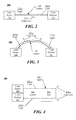
- the sensor 400 includes the light source 432, the light detector 434 and the lumen 436.
- the light source 432 and the light detector 434 are operably connected to the lumen 436.
- the lumen 436 includes a conical end 438.
- light e.g., light 435-a
- the conical end 438 During operation, light (e.g., light 435-a) is emitted from the light source 432 and transmitted down the lumen 436 to the conical end 438.
- the conical end 438 Due to the conical shape of the conical end 438, a portion (e.g., 435-b) of the light 435-a is reflected back up the lumen 436 to the light detector 434 while another portion (e.g., 435-c) of the light 435-a escapes from the lumen 436, and particularly from the conical end 438.
- the conical end 438 is configured to reflect at least a portion of the light received from the light source 432 located adjacent a first end opposite the conical end, where the reflected light is transmitted from the second end through the lumen 436 back to the first end.
- light emitted from the light source 432 may undergo multiple internal reflections within the conical end 428 of lumen 436 before a portion of the light incident on the conical end 428 is returned to the light detector 434.
- the concentration and/or quality of the urea solution 120 changes, the refractive index of the urea solution 120 also changes and the amount of light 435-b reflected back to the light detector 434 may change accordingly.
- the concentration and/or quality of the urea solution 120 can be determined.
- a relationship between concentration of urea solution 120 or other quality of urea solution 120 and the refractive index of the urea solution may be known.
- the amount of light 435-b such as a percentage of the amount of light 435-a, may also be used to indicate the refractive index of the urea solution 120, since the amount of reflected light at the interface of the lumen 436 and urea solution 120 may vary with refractive index. Accordingly, the amount of percentage of light 435-b with respect to the amount of light 435-a may be a convenient measure of a quality of the urea solution 120 such as refractive index.
- An advantage afforded by the arrangement of the sensor 4 of FIG. 4 is the ability to locate a light source and light detector adjacent one another.
- the lumen 136 of the sensor 130 may be a porous optical fiber.
- the lumen 136 may have pores to increase the surface area between the lumen 136 and the urea solution 120 as compared to a non-porous optical fiber. The increased surface area may increase the sensitivity of the sensor 130 and may provide for finer grained detection between changes in the refractive index of the urea solution 120.
- FIG. 5 is a logic flow for a method 500 for determining a concentration and/or quality of urea solution.
- the system 100 and or the sensors 200, 300, and/or 400 may implement the method 500.
- the method 500 may begin at block 510.
- a portion of the light emitted by the light source and transmitted through the lumen will escape the lumen. Accordingly the detector receives the portion (e.g., the portion that does not escape from the lumen) of light emitted by the source.
- the controller 140 may determine the quality and/or concentration of the urea solution 120 based on the first quantity of light and the second quantity of light. Said differently the controller 140 may determine the quality and/or concentration of the urea solution based on the amount (e.g., amplitude, or the like) of light emitted by the source and the amount (e.g., amplitude, or the like) of light received by the detector.
- the amount e.g., amplitude, or the like
- the present embodiments may be usefully employed to monitor and control other systems of liquid solutions where a first substance is dissolved in a liquid solution, to the extent that changes in the concentration of the first substance, or presence of impurities, may change the refractive index of the solution.
- Examples include measuring the alcohol content in an automobile fuel, where the automobile fuel may include a liquid solution of alcohol and hydrocarbon liquids.
- changes in alcohol concentration may engender changes in refractive index that are detectable as changes in the amount of light detected in a sensor of the aforementioned embodiments.
- references to "an embodiment,” “an implementation,” “an example,” and/or equivalents is not intended to be interpreted as excluding the existence of additional embodiments that also incorporate the recited features.
Abstract
Description
- This present application claims priority to
U.S. provisional patent application No. 61/983,028, filed Apr 23, 2014 - This disclosure relates generally to the field of liquid condition sensing and particularly to sensing characteristics of urea solution in a urea tank, such as, for example, urea for use in a motor vehicle.
- Urea, or urea based solutions are often used in automotive application to reduce emissions. For example, some diesel powered motor vehicles include a urea tank, separate from the fuel tank, which is used to carry an operating fluid such as an automotive urea solution, or the like. The urea solution is stored in the urea tank and is sprayed into the exhaust gases of the vehicle in order to convert oxides of nitrogen into elementary nitrogen and water. Accordingly, the harmful emissions of the vehicle are reduced. As will be appreciated, various countries in the world have regulated that some vehicles include urea based emissions systems in order to comply with emissions standards. These systems are sometimes referred to as Selective Catalytic Reduction (SCR) system or SCR vehicles.
- In order for SCR vehicles to properly regulate and reduce exhaust gas emissions, information related to the composition of the urea solution is used to properly adjust certain vehicle parameters and to optimize vehicle performance. In particular, such information is used to control of the emissions system. One characteristic about the urea solution that is useful for operation is the "quality" of the urea. As will be appreciated, contaminants, changes in the ratio of urea to other constituents in the solution, temperature variation, as well as other changes can impact the life expectancy and the effectiveness of the urea solution.
- One known sensor proposes to use radio frequency (RF) waves to measure the quality and concentration of urea. This sensor is explained in greater detail in
U.S. Patent Application No. 12/803,331, filed on June 24, 2010 PCT Application No. EP2012/063055 filed June 4, 2012 - In one embodiment, a sensor to measure a liquid may include a light source operably coupled to a lumen disposed in a liquid solution, the light source configured to emit light and communicate the light to the lumen. The sensor may further include a light detector operably coupled to the lumen, the light detector configured to receive at least a portion of the light from the lumen; and a controller configured to determine a concentration or quality of the liquid solution based on the light emitted by the light source and the portion of light received by the light detector.
- In another embodiment, a sensor to measure a urea solution may include a light source operably coupled to a lumen disposed in a urea solution, the light source configured to emit light and communicate the light to the lumen. The sensor may further include a light detector operably coupled to the lumen, the light detector configured to receive at least a portion of the light from the lumen, a controller configured to determine a concentration or quality of the urea solution based upon a ratio of a first light amplitude corresponding to the light emitted by the light source and a second light amplitude corresponding to the portion of light received by the light detector.
- In a further embodiment a method of measuring a liquid includes emitting a first quantity of light from a light source attached to a lumen disposed in a liquid solution; transmitting the first quantity of light through the lumen; receiving a second quantity of light at a light detector attached to the lumen; and determining a concentration or quality of the liquid solution based on the first quantity of light and the second quantity of light.
- By way of example, specific embodiments of the disclosed device will now be described, with reference to the accompanying drawings, in which:
-
FIG. 1 is a block diagram of a system for measuring the concentration and/or quality of urea; -
FIGS. 2-4 are block diagrams of sensors that may be implemented in the system ofFIG. 1 ; -
FIG. 5 is a block diagram of a logic flow for measuring concentration and/or quality of a urea solution, arranged according to at least some embodiments of the present disclosure. -
FIG. 1 is a block diagram of asystem 100 for measuring urea quality and/or concentration according to embodiments of the present disclosure. As depicted, thesystem 100 includes atank 110 havingurea solution 120 disposed therein. Thetank 110 may be made from a variety of materials, such as, for example, plastic, composite, metal, or the like. In general, thetank 110 will be a non-conductive material. The urea solution may be a variety of urea solutions. Furthermore, while the present disclosure is related to measuring the quality and concentration of urea, it could be applied to other liquids, such as, for example, measuring the alcohol content in an automobile fuel, or the like. - A
sensor 130 is also disposed within thetank 110 and operably coupled to acontroller 140. Various example embodiments of thesensor 130 are described below with reference toFIGS. 2-4 . In general thesensor 130 includes alight source 132 and alight detector 134 optically connected to one another via alumen 136. In general, thesensor 130 is used to measure the concentration and/or quality of theurea solution 120 based on the refractive index of theurea solution 120. More specifically, light is passed from thelight source 132 to thelight detector 134 via thelumen 136. As the light propagates from thelight source 132 to thelight detector 134, some light will escape from thelumen 136. In particular, at least a portion of thelumen 136 may be directly immersed in theurea solution 120. - As noted above, for certain applications, such as in vehicle exhaust systems, information concerning a concentration of urea in a urea solution may be useful for proper operation. For example, a target composition for a solution may be a concentration of urea dissolved in water, such as approximately 33% urea and 67% water. The embodiments are not limited in this context.
- In the present embodiments, techniques and apparatus may be applied to determine properties of a liquid solution where the refractive index may be variable according to a concentration of a substance with the liquid solution. For example, as the concentration and/or quality of the
urea solution 120 changes, the refractive index of theurea solution 120 may also change. As such, the amount of light escaping from thelumen 136 may change accordingly. This is because the angle of internal reflection of light traveling through thelumen 136 and striking an interface between thelumen 136 andurea solution 120 varies with refractive index of theurea solution 120. As the angle of internal reflection changes for a given amount of light in thelumen 136, the amount of light not internally reflected and instead escaping thelumen 136 changes. Therefore, by measuring the amount of light escaping thelumen 136, or the amount of light received by thelight detector 134, changes in the refractive index of theurea solution 120 may be determined. Accordingly, based upon knowledge of the relationship between refractive index and urea concentration or quality of the solution, thesensor 130 in conjunction with thecontroller 140 may measure the concentration and/or quality of theurea solution 120 based on the amount of light received at thelight detector 134, or alternatively the amount of escaped light. Because the refractive index of urea solutions may be readily known or measurable, the present embodiments provide a useful manner for monitoring changes in urea solutions as well as controlling systems that employ such solutions. - In general, the
light source 132 can be any of a variety of types of light sources and thelight detector 134 can be any of a variety of types of light detectors. For example, thelight source 132 may be a light emitting diode (LED). Thelight detector 134 may be a photo-detector, a photo-diode, or the like. Thelumen 136 may be any of a variety of light carrying lumens. For example, thelumen 136 may be a fiber optic cable. Furthermore, thelumen 136 may be uncoated and/or porous. - The
controller 140 may include aprocessor 142 and amemory 144. In general, theprocessor 142 may be configured to execute one or more instructions to cause thesensor 130 to operate and measure the concentration and/or quality of theurea solution 120. For example, the processor may be configured to execute instructions to cause thelight source 132 to emit a first quantity of light and to receive a signal (e.g., electric signal) from thelight detector 134 indicative of a second quantity of light that corresponds to the amount of light received by thelight detector 134. - The
processor 142 may further be configured to determine a concentration and/or quality of theurea solution 120 based on the amount of light emitted by thelight source 132 and the amount of light received by thelight detector 134. Said differently, thecontroller 140 may be configured to determine a quantity and/or concentration of theurea solution 120 based on the first quantity of light (e.g., light emitted by the source) and the second quantity of light (e.g., light received by the detector). As used herein the term "concentration of urea" may refer to the concentration of urea within a liquid solution that includes another liquid such as water. - With some example, the
processor 142 may be a general purpose processor, a microprocessor, an FPGA, an ASIC, or in general, any computing device configured to execute instructions. Thememory 144 may be a computer readable medium, including non-volatile computer readable medium and/or non-transient computer readable medium configured to store computer executable instructions, that when executed by theprocessor 142, cause the processor to perform one or more operations. -
FIGS. 2-4 are block diagrams of examples urea quality and/or concentration sensors according to the present disclosure. In particular, these figures depict examples of thesensor 130 ofFIG. 1 . Notably, the sensors described with respect toFIGS.2-4 are described with reference to thesystem 100 ofFIG. 1 . This is not intended to be limiting and the sensors depicted and described herein can be implemented in systems with more, less, or different configurations that than shown inFIG. 1 . - Turning more specifically to
FIG. 2 , asensor 200 is shown. Thesensor 200 includes the light source 232, thelight detector 234 and thelumen 236. In particular, the light source 232 and thelight detector 234 are operably coupled by thelumen 236. As depicted, thelumen 236 is straight. In some examples, thelumen 236 may be an uncoated fiber optic cable, or uncoated optical fiber. During operation, thecontroller 140 may cause the light source 232 to emit light, which travels down thelumen 236 and is received by thelight detector 234. As with the embodiment ofFIG. 1 and similarly in the embodiments ofFIG. 3 and FIG. 4 , at least a portion of thelumen 236 may be directly immersed in theurea solution 120. The amplitude of the received light is measured and the quality and/or concentration of theurea solution 120 can be measured based on the received amplitude. More particularly, the light emits a quantity (e.g., amplitude, power, frequency, or the like) of light 235-a. As the light 235-a propagates through thelumen 236, a portion of the light escapes the lumen as light loss 235-c. Accordingly, just a portion of the light 235-a may be received by thelight detector 234. This portion of light is represented as light 235-b. Accordingly, the amount of light 235-c that escaped thelumen 236 can be determined based on the amplitude of the received light 235-b. The received light 235-b and/or the escaped light 235-c can be used to determine the refractive index of theurea solution 120, which can in turn be used to determine the concentration and/or quality of theurea solution 120, as discussed above. - Turning more specifically to
FIG. 3 , asensor 300 is shown. Thesensor 300 includes the light source 332, thelight detector 334 and thelumen 336. In particular, the light source 332 and thelight detector 334 are operably coupled to thelumen 336. As depicted, thelumen 336 is bent. Thelumen 336 may be, for example, a bent optical fiber. It is to be appreciated, that thelumen 336 may include one bent section, more bends and/or bends of alternative configuration than that shown inFIG. 3 . For example, thelumen 336 may be "S" shaped, "Z" shaped, or the like. The operation of thesensor 300 is similar to the operation of thesensor 200 in that the light source 332 emits light that travels through thelumen 336 and is received by thelight detector 334. Notably, due to the overall shape of thelumen 336 and particularly the bent portion, an increased amount of light may escape from the lumen. For example, light 335-a emitted by the light source 232 and light 235-b received by the detector are depicted. Additionally, light loss 235-c is depicted. The bent portions of thelumen 336 may be configured to increase the sensitivity of the sensor. In particular, the level of concentration and/or quality of urea solution that may be determined may be increased. - Turning more specifically to
FIG. 4 , asensor 400 is shown. Thesensor 400 includes the light source 432, thelight detector 434 and thelumen 436. In particular, the light source 432 and thelight detector 434 are operably connected to thelumen 436. Additionally, thelumen 436 includes aconical end 438. During operation, light (e.g., light 435-a) is emitted from the light source 432 and transmitted down thelumen 436 to theconical end 438. Due to the conical shape of theconical end 438, a portion (e.g., 435-b) of the light 435-a is reflected back up thelumen 436 to thelight detector 434 while another portion (e.g., 435-c) of the light 435-a escapes from thelumen 436, and particularly from theconical end 438. In other words, theconical end 438 is configured to reflect at least a portion of the light received from the light source 432 located adjacent a first end opposite the conical end, where the reflected light is transmitted from the second end through thelumen 436 back to the first end. - In the example of
FIG. 4 light emitted from the light source 432 may undergo multiple internal reflections within the conical end 428 oflumen 436 before a portion of the light incident on the conical end 428 is returned to thelight detector 434. - As the concentration and/or quality of the
urea solution 120 changes, the refractive index of theurea solution 120 also changes and the amount of light 435-b reflected back to thelight detector 434 may change accordingly. As a result, the concentration and/or quality of theurea solution 120 can be determined. In other words, a relationship between concentration ofurea solution 120 or other quality ofurea solution 120 and the refractive index of the urea solution may be known. The amount of light 435-b, such as a percentage of the amount of light 435-a, may also be used to indicate the refractive index of theurea solution 120, since the amount of reflected light at the interface of thelumen 436 andurea solution 120 may vary with refractive index. Accordingly, the amount of percentage of light 435-b with respect to the amount of light 435-a may be a convenient measure of a quality of theurea solution 120 such as refractive index. - An advantage afforded by the arrangement of the sensor 4 of
FIG. 4 is the ability to locate a light source and light detector adjacent one another. - With some examples, the
lumen 136 of the sensor 130 (e.g., thelumen lumen 136 may have pores to increase the surface area between thelumen 136 and theurea solution 120 as compared to a non-porous optical fiber. The increased surface area may increase the sensitivity of thesensor 130 and may provide for finer grained detection between changes in the refractive index of theurea solution 120. -
FIG. 5 is a logic flow for amethod 500 for determining a concentration and/or quality of urea solution. In some examples, thesystem 100 and or thesensors method 500. - The
method 500 may begin atblock 510. Atblock 510, emit a first quantity of light from a light source attached to a lumen disposed in a urea solution; thelight source 132 may emit a first quantity of light and communicate the light to thelumen 136. Atblock 520, transmit the first quantity of light through the lumen; the first quantity of light may be transmitted through thelumen 136, which is disposed in theurea solution 120. Atblock 530, receive a second quantity of light at a light detector attached to the lumen; thelight detector 134 may receive a second quantity of light. As detailed above, a portion of the light emitted by the light source and transmitted through the lumen will escape the lumen. Accordingly the detector receives the portion (e.g., the portion that does not escape from the lumen) of light emitted by the source. - Continuing to block 540, determine a concentration and/or quality of the urea solution based on the first quantity of light and the second quantity of light; the
controller 140 may determine the quality and/or concentration of theurea solution 120 based on the first quantity of light and the second quantity of light. Said differently thecontroller 140 may determine the quality and/or concentration of the urea solution based on the amount (e.g., amplitude, or the like) of light emitted by the source and the amount (e.g., amplitude, or the like) of light received by the detector. - As noted above, the present embodiments may be usefully employed to monitor and control other systems of liquid solutions where a first substance is dissolved in a liquid solution, to the extent that changes in the concentration of the first substance, or presence of impurities, may change the refractive index of the solution. Examples include measuring the alcohol content in an automobile fuel, where the automobile fuel may include a liquid solution of alcohol and hydrocarbon liquids. In such systems, changes in alcohol concentration may engender changes in refractive index that are detectable as changes in the amount of light detected in a sensor of the aforementioned embodiments.
- As used herein, references to "an embodiment," "an implementation," "an example," and/or equivalents is not intended to be interpreted as excluding the existence of additional embodiments that also incorporate the recited features.
- While the present disclosure has been made with reference to certain embodiments, numerous modifications, alterations and changes to the described embodiments are possible without departing from the sphere and scope of the present embodiments, as defined in the appended claim(s). Accordingly, it is intended that the present disclosure not be limited to the described embodiments, but that it has the full scope defined by the language of the following claims, and equivalents thereof.
Claims (18)
- A sensor to measure a liquid, comprising:a light source operably coupled to a lumen disposed in a liquid solution, the light source configured to emit light and communicate the light to the lumen;a light detector operably coupled to the lumen, the light detector configured to receive at least a portion of the light from the lumen; anda controller configured to determine a concentration or quality of the liquid solution based on the light emitted by the light source and the portion of the light received by the light detector.
- The sensor of claim 1, wherein the liquid solution is a urea solution.
- The sensor of claim 1, wherein the lumen is an uncoated fiber optic cable.
- The sensor of claim 3, wherein the lumen is a porous optical fiber.
- The sensor of claim 4, wherein the porous optical fiber presents an increased surface area to the liquid solution compared to a non-porous optical fiber.
- The sensor of claim 1, wherein the lumen includes at least one bent section.
- The sensor of claim 1, wherein the light source and the light detector are operably connected to a first end of the lumen and a second end of the lumen is conical shaped.
- The sensor of claim 7, wherein the second end is configured to reflect at least a portion of light emitted by the light source to the first end.
- A sensor to measure a urea solution, comprising:a light source operably coupled to a lumen disposed in a urea solution, the light source configured to emit light and communicate the light to the lumen;a light detector operably coupled to the lumen, the light detector configured to receive at least a portion of the light from the lumen; anda controller configured to determine a concentration or quality of the urea solution based upon a ratio of a first light amplitude corresponding to the light emitted by the light source and a second light amplitude corresponding to the portion of the light received by the light detector.
- The sensor of claim 9, wherein the lumen is an uncoated optical fiber.
- The sensor of claim 10, wherein the lumen is a porous optical fiber.
- The sensor of claims 9, 10 or 11, wherein the lumen includes at least one bent section.
- A method of measuring a liquid, comprising:emitting a first quantity of light from a light source attached to a lumen disposed in a liquid solution;transmitting the first quantity of light through the lumen;receiving a second quantity of light at a light detector attached to the lumen; anddetermining a concentration or quality of the liquid solution based on the first quantity of light and the second quantity of light.
- The method of claim 13, wherein the lumen is a fiber optic cable.
- The method of claim 13, wherein a refractive index of the liquid solution is variable according to a concentration of a substance with the liquid solution.
- The method of claim 15, wherein the liquid solution is a urea solution.
- The method of claim 13, wherein the light source and the light detector are disposed adjacent a first end of the lumen, the method further comprising providing a conical shape to a second end of the lumen, wherein at least a portion of the first quantity of light is reflected from the second end to the first end.
- The method of claim 13, further comprising providing the lumen as a bent optical fiber.
Priority Applications (1)
| Application Number | Priority Date | Filing Date | Title |
|---|---|---|---|
| PL15164811T PL2937537T3 (en) | 2014-04-23 | 2015-04-23 | Urea concentration sensor |
Applications Claiming Priority (1)
| Application Number | Priority Date | Filing Date | Title |
|---|---|---|---|
| US201461983028P | 2014-04-23 | 2014-04-23 |
Publications (2)
| Publication Number | Publication Date |
|---|---|
| EP2937537A1 true EP2937537A1 (en) | 2015-10-28 |
| EP2937537B1 EP2937537B1 (en) | 2016-12-07 |
Family
ID=52997971
Family Applications (1)
| Application Number | Title | Priority Date | Filing Date |
|---|---|---|---|
| EP15164811.0A Active EP2937537B1 (en) | 2014-04-23 | 2015-04-23 | Urea concentration sensor |
Country Status (5)
| Country | Link |
|---|---|
| US (1) | US20150308952A1 (en) |
| EP (1) | EP2937537B1 (en) |
| CN (1) | CN105044027B (en) |
| ES (1) | ES2615121T3 (en) |
| PL (1) | PL2937537T3 (en) |
Cited By (3)
| Publication number | Priority date | Publication date | Assignee | Title |
|---|---|---|---|---|
| ITUA20161342A1 (en) * | 2016-03-04 | 2017-09-04 | Eltek Spa | SENSOR DEVICE FOR CONTAINERS OF LIQUID SUBSTANCES |
| EP3734237A1 (en) * | 2019-05-02 | 2020-11-04 | TE Connectivity Norge AS | Sensor system and method for measuring a fluid level and/or a fluid quality |
| WO2022189680A1 (en) | 2021-03-08 | 2022-09-15 | Sensing Solutions S.L. | Component for deploying optical probes, and optical probe |
Families Citing this family (8)
| Publication number | Priority date | Publication date | Assignee | Title |
|---|---|---|---|---|
| JP6049058B2 (en) * | 2012-10-09 | 2016-12-21 | 株式会社サンエー | Fluid state identification device |
| EP3001181B1 (en) * | 2014-09-24 | 2018-02-28 | Littelfuse Italy S.r.l. | Device for detecting the concentration of urea in solution with water |
| ITUA20161345A1 (en) * | 2016-03-04 | 2017-09-04 | Eltek Spa | SENSOR DEVICE FOR CONTAINERS OF LIQUID SUBSTANCES |
| EP3534150B1 (en) * | 2016-10-25 | 2022-07-06 | Air Water Biodesign Inc. | Fluid measuring device |
| CN109162786B (en) * | 2018-08-31 | 2021-06-01 | 珠海领航电气有限公司 | Method and device for preventing solution from crystallizing and solution storage tank |
| CN110779986A (en) * | 2019-11-06 | 2020-02-11 | 武汉沐之盛电子科技有限公司 | Be applied to two probes of urea quality sensor |
| EP4083609A4 (en) * | 2019-12-24 | 2024-01-24 | Kubota Kk | Urea concentration sensor and ammonia concentration sensor |
| CN112147082A (en) * | 2020-09-24 | 2020-12-29 | 杭州春来科技有限公司 | Vehicle-mounted urea monitoring device and monitoring method |
Citations (4)
| Publication number | Priority date | Publication date | Assignee | Title |
|---|---|---|---|---|
| US5250095A (en) * | 1988-08-16 | 1993-10-05 | Rutgers University | Method for making porous glass optical fiber sensor |
| US20090034901A1 (en) * | 2005-05-26 | 2009-02-05 | Mitsubishi Electric Corporation | Optical fiber sensor |
| US20110043799A1 (en) * | 2009-08-24 | 2011-02-24 | Mitsubishi Electric Corporation | Optical fiber sensor and fuel supply apparatus having the same |
| DE102011089703B3 (en) * | 2011-12-22 | 2013-05-23 | Continental Automotive Gmbh | Optical measuring arrangement for determination of e.g. light speed within diesel fuel in motor car, has light sources whose light is incident at certain angle different from another angle and reflected to light sensors |
Family Cites Families (12)
| Publication number | Priority date | Publication date | Assignee | Title |
|---|---|---|---|---|
| US4240747A (en) * | 1979-10-03 | 1980-12-23 | Battelle Memorial Institute | Refractive-index responsive light-signal system |
| CN2067830U (en) * | 1990-02-07 | 1990-12-19 | 杨淑雯 | Sensor for measuring liquid concentration |
| US5894535A (en) * | 1997-05-07 | 1999-04-13 | Hewlett-Packard Company | Optical waveguide device for wavelength demultiplexing and waveguide crossing |
| US7062125B2 (en) * | 2003-04-08 | 2006-06-13 | Institut National D'optique | Prismatic reflection optical waveguide device |
| CN1627057A (en) * | 2003-12-11 | 2005-06-15 | 河南新飞电器有限公司 | Method for measuring strength of fluid and measuring device |
| JP5131806B2 (en) * | 2006-08-21 | 2013-01-30 | 独立行政法人産業技術総合研究所 | Optical waveguide mode sensor with pores |
| JP5008366B2 (en) * | 2006-09-26 | 2012-08-22 | Udトラックス株式会社 | Engine exhaust purification system |
| US20120071580A1 (en) * | 2008-07-31 | 2012-03-22 | The Board Of Trustees Of The University Of Illinois | Suturable Hybrid Superporous Hydrogel Keratoprosthesis for Cornea |
| CN102095701B (en) * | 2010-11-12 | 2013-05-08 | 重庆大学 | Method for online separation and measurement of biomass concentration by optical fiber attenuation total-reflection sensor |
| CN102012359B (en) * | 2010-11-19 | 2012-03-28 | 华中科技大学 | Liquid multi-parameter sensor |
| DE102010053737A1 (en) * | 2010-12-08 | 2012-06-14 | Voss Automotive Gmbh | Heatable fluid conduit, its use and process for its preparation |
| US9324984B2 (en) * | 2013-02-01 | 2016-04-26 | GM Global Technology Operations LLC | Direct formation of a separator with a protective edge on an electrode |
-
2015
- 2015-04-22 US US14/693,279 patent/US20150308952A1/en not_active Abandoned
- 2015-04-23 EP EP15164811.0A patent/EP2937537B1/en active Active
- 2015-04-23 PL PL15164811T patent/PL2937537T3/en unknown
- 2015-04-23 CN CN201510197188.8A patent/CN105044027B/en active Active
- 2015-04-23 ES ES15164811.0T patent/ES2615121T3/en active Active
Patent Citations (4)
| Publication number | Priority date | Publication date | Assignee | Title |
|---|---|---|---|---|
| US5250095A (en) * | 1988-08-16 | 1993-10-05 | Rutgers University | Method for making porous glass optical fiber sensor |
| US20090034901A1 (en) * | 2005-05-26 | 2009-02-05 | Mitsubishi Electric Corporation | Optical fiber sensor |
| US20110043799A1 (en) * | 2009-08-24 | 2011-02-24 | Mitsubishi Electric Corporation | Optical fiber sensor and fuel supply apparatus having the same |
| DE102011089703B3 (en) * | 2011-12-22 | 2013-05-23 | Continental Automotive Gmbh | Optical measuring arrangement for determination of e.g. light speed within diesel fuel in motor car, has light sources whose light is incident at certain angle different from another angle and reflected to light sensors |
Cited By (5)
| Publication number | Priority date | Publication date | Assignee | Title |
|---|---|---|---|---|
| ITUA20161342A1 (en) * | 2016-03-04 | 2017-09-04 | Eltek Spa | SENSOR DEVICE FOR CONTAINERS OF LIQUID SUBSTANCES |
| WO2017149475A1 (en) * | 2016-03-04 | 2017-09-08 | Eltek S.P.A. | Sensor device for containers of liquid substances |
| US10677725B2 (en) | 2016-03-04 | 2020-06-09 | Eltek S.P.A. | Sensor device for containers of liquid substances |
| EP3734237A1 (en) * | 2019-05-02 | 2020-11-04 | TE Connectivity Norge AS | Sensor system and method for measuring a fluid level and/or a fluid quality |
| WO2022189680A1 (en) | 2021-03-08 | 2022-09-15 | Sensing Solutions S.L. | Component for deploying optical probes, and optical probe |
Also Published As
| Publication number | Publication date |
|---|---|
| EP2937537B1 (en) | 2016-12-07 |
| ES2615121T3 (en) | 2017-06-05 |
| PL2937537T3 (en) | 2017-11-30 |
| US20150308952A1 (en) | 2015-10-29 |
| CN105044027A (en) | 2015-11-11 |
| CN105044027B (en) | 2019-11-26 |
Similar Documents
| Publication | Publication Date | Title |
|---|---|---|
| EP2937537B1 (en) | Urea concentration sensor | |
| KR102230828B1 (en) | Method and apparatus for monitoring tank contents of storage tank of exhaust gas treatment system | |
| EA201790118A1 (en) | DETECTING SYSTEM FOR DETECTION OF CONTAINER PLUNGER | |
| US10254390B2 (en) | Method for operating an ultrasonic sensor apparatus of a motor vehicle, ultrasonic sensor apparatus, and motor vehicle | |
| US10451734B2 (en) | Object detecting apparatus | |
| CN106537183B (en) | Method for operating a motor vehicle and motor vehicle | |
| US10775348B2 (en) | System for measuring a parameter of a fluid in a tank | |
| WO2013122646A3 (en) | Systems and methods for analyte detection | |
| JP2019521035A (en) | Optical air data system and method | |
| US20140132951A1 (en) | Device for measuring urea concentration | |
| CN203811241U (en) | Laser liquid level detection device for transparent pipeline | |
| US10605644B2 (en) | Complementary apparatus for measuring urea water level | |
| JP5376440B2 (en) | Optical remote airflow measurement device | |
| RU2016129694A (en) | IDENTIFICATION AND QUANTITATIVE DETERMINATION OF LEAKS OF AMMONIA AFTER THE SYSTEM OF SELECTIVE CATALYTIC REDUCTION OF NITROGEN OXIDES | |
| US8295657B2 (en) | Optical fiber sensor and fuel supply apparatus having the same | |
| KR20140036319A (en) | Method and device for testing a liquid | |
| US20120257202A1 (en) | Concentration measuring device, concentration measuring arrangement and concentration measuring method | |
| CN106033051B (en) | Device for detecting solution concentration | |
| US10901228B2 (en) | Cavity with curved beam replicator and method of determining a characteristic of a medium therein | |
| KR101787269B1 (en) | Apparatus for diagnosing ultrasound sensor | |
| EP3734237B1 (en) | Sensor system and method for measuring a fluid level and/ or a fluid quality | |
| US20100084558A1 (en) | Systems and methods for determining a concentration of urea in an aqueous solution | |
| CN106054199B (en) | Unmanned plane, ultrasonic ranging method and device | |
| EP3482198B1 (en) | Method for detecting a malfunction of an ultrasonic fluid sensing system | |
| CN103290765A (en) | Automatic ultrasonic detection device for travelling surface gathered water |
Legal Events
| Date | Code | Title | Description |
|---|---|---|---|
| PUAI | Public reference made under article 153(3) epc to a published international application that has entered the european phase |
Free format text: ORIGINAL CODE: 0009012 |
|
| AK | Designated contracting states |
Kind code of ref document: A1 Designated state(s): AL AT BE BG CH CY CZ DE DK EE ES FI FR GB GR HR HU IE IS IT LI LT LU LV MC MK MT NL NO PL PT RO RS SE SI SK SM TR |
|
| AX | Request for extension of the european patent |
Extension state: BA ME |
|
| 17P | Request for examination filed |
Effective date: 20160428 |
|
| RBV | Designated contracting states (corrected) |
Designated state(s): AL AT BE BG CH CY CZ DE DK EE ES FI FR GB GR HR HU IE IS IT LI LT LU LV MC MK MT NL NO PL PT RO RS SE SI SK SM TR |
|
| GRAP | Despatch of communication of intention to grant a patent |
Free format text: ORIGINAL CODE: EPIDOSNIGR1 |
|
| RIC1 | Information provided on ipc code assigned before grant |
Ipc: B60K 15/03 20060101ALN20160525BHEP Ipc: G01N 21/552 20140101AFI20160525BHEP Ipc: B60K 13/04 20060101ALI20160525BHEP Ipc: F01N 11/00 20060101ALI20160525BHEP Ipc: G01N 21/85 20060101ALI20160525BHEP Ipc: F01N 3/20 20060101ALI20160525BHEP |
|
| INTG | Intention to grant announced |
Effective date: 20160610 |
|
| GRAJ | Information related to disapproval of communication of intention to grant by the applicant or resumption of examination proceedings by the epo deleted |
Free format text: ORIGINAL CODE: EPIDOSDIGR1 |
|
| REG | Reference to a national code |
Ref country code: DE Ref legal event code: R079 Ref document number: 602015000904 Country of ref document: DE Free format text: PREVIOUS MAIN CLASS: F01N0003200000 Ipc: G01N0021552000 |
|
| INTC | Intention to grant announced (deleted) | ||
| GRAS | Grant fee paid |
Free format text: ORIGINAL CODE: EPIDOSNIGR3 |
|
| GRAP | Despatch of communication of intention to grant a patent |
Free format text: ORIGINAL CODE: EPIDOSNIGR1 |
|
| RIC1 | Information provided on ipc code assigned before grant |
Ipc: B60K 15/03 20060101ALN20160829BHEP Ipc: B60K 13/04 20060101ALI20160829BHEP Ipc: F01N 3/20 20060101ALI20160829BHEP Ipc: G01N 21/85 20060101ALI20160829BHEP Ipc: F01N 11/00 20060101ALI20160829BHEP Ipc: G01N 21/552 20140101AFI20160829BHEP |
|
| INTG | Intention to grant announced |
Effective date: 20160929 |
|
| STAA | Information on the status of an ep patent application or granted ep patent |
Free format text: STATUS: GRANT OF PATENT IS INTENDED |
|
| GRAA | (expected) grant |
Free format text: ORIGINAL CODE: 0009210 |
|
| STAA | Information on the status of an ep patent application or granted ep patent |
Free format text: STATUS: THE PATENT HAS BEEN GRANTED |
|
| AK | Designated contracting states |
Kind code of ref document: B1 Designated state(s): AL AT BE BG CH CY CZ DE DK EE ES FI FR GB GR HR HU IE IS IT LI LT LU LV MC MK MT NL NO PL PT RO RS SE SI SK SM TR |
|
| REG | Reference to a national code |
Ref country code: GB Ref legal event code: FG4D |
|
| REG | Reference to a national code |
Ref country code: CH Ref legal event code: EP Ref country code: AT Ref legal event code: REF Ref document number: 852182 Country of ref document: AT Kind code of ref document: T Effective date: 20161215 |
|
| REG | Reference to a national code |
Ref country code: IE Ref legal event code: FG4D |
|
| REG | Reference to a national code |
Ref country code: DE Ref legal event code: R096 Ref document number: 602015000904 Country of ref document: DE |
|
| PG25 | Lapsed in a contracting state [announced via postgrant information from national office to epo] |
Ref country code: LV Free format text: LAPSE BECAUSE OF FAILURE TO SUBMIT A TRANSLATION OF THE DESCRIPTION OR TO PAY THE FEE WITHIN THE PRESCRIBED TIME-LIMIT Effective date: 20161207 |
|
| REG | Reference to a national code |
Ref country code: SE Ref legal event code: TRGR |
|
| REG | Reference to a national code |
Ref country code: LT Ref legal event code: MG4D |
|
| REG | Reference to a national code |
Ref country code: NL Ref legal event code: MP Effective date: 20161207 |
|
| REG | Reference to a national code |
Ref country code: FR Ref legal event code: PLFP Year of fee payment: 3 |
|
| PG25 | Lapsed in a contracting state [announced via postgrant information from national office to epo] |
Ref country code: GR Free format text: LAPSE BECAUSE OF FAILURE TO SUBMIT A TRANSLATION OF THE DESCRIPTION OR TO PAY THE FEE WITHIN THE PRESCRIBED TIME-LIMIT Effective date: 20170308 Ref country code: LT Free format text: LAPSE BECAUSE OF FAILURE TO SUBMIT A TRANSLATION OF THE DESCRIPTION OR TO PAY THE FEE WITHIN THE PRESCRIBED TIME-LIMIT Effective date: 20161207 Ref country code: NO Free format text: LAPSE BECAUSE OF FAILURE TO SUBMIT A TRANSLATION OF THE DESCRIPTION OR TO PAY THE FEE WITHIN THE PRESCRIBED TIME-LIMIT Effective date: 20170307 |
|
| REG | Reference to a national code |
Ref country code: AT Ref legal event code: MK05 Ref document number: 852182 Country of ref document: AT Kind code of ref document: T Effective date: 20161207 |
|
| PG25 | Lapsed in a contracting state [announced via postgrant information from national office to epo] |
Ref country code: HR Free format text: LAPSE BECAUSE OF FAILURE TO SUBMIT A TRANSLATION OF THE DESCRIPTION OR TO PAY THE FEE WITHIN THE PRESCRIBED TIME-LIMIT Effective date: 20161207 Ref country code: FI Free format text: LAPSE BECAUSE OF FAILURE TO SUBMIT A TRANSLATION OF THE DESCRIPTION OR TO PAY THE FEE WITHIN THE PRESCRIBED TIME-LIMIT Effective date: 20161207 Ref country code: RS Free format text: LAPSE BECAUSE OF FAILURE TO SUBMIT A TRANSLATION OF THE DESCRIPTION OR TO PAY THE FEE WITHIN THE PRESCRIBED TIME-LIMIT Effective date: 20161207 |
|
| REG | Reference to a national code |
Ref country code: ES Ref legal event code: FG2A Ref document number: 2615121 Country of ref document: ES Kind code of ref document: T3 Effective date: 20170605 |
|
| PG25 | Lapsed in a contracting state [announced via postgrant information from national office to epo] |
Ref country code: NL Free format text: LAPSE BECAUSE OF FAILURE TO SUBMIT A TRANSLATION OF THE DESCRIPTION OR TO PAY THE FEE WITHIN THE PRESCRIBED TIME-LIMIT Effective date: 20161207 |
|
| REG | Reference to a national code |
Ref country code: DE Ref legal event code: R081 Ref document number: 602015000904 Country of ref document: DE Owner name: SUZHOU LITTELFUSE OVS CO., LTD., SUZHOU, CN Free format text: FORMER OWNER: LITTELFUSE, INC., CHICAGO, ILL., US Ref country code: DE Ref legal event code: R082 Ref document number: 602015000904 Country of ref document: DE Representative=s name: MURGITROYD & COMPANY, DE Ref country code: DE Ref legal event code: R081 Ref document number: 602015000904 Country of ref document: DE Owner name: HAMLIN ELECTRONICS (SUZHOU) CO. LTD., SUZHOU, CN Free format text: FORMER OWNER: LITTELFUSE, INC., CHICAGO, ILL., US Ref country code: DE Ref legal event code: R081 Ref document number: 602015000904 Country of ref document: DE Owner name: SUZHOU LITTELFUSE OVS, LTD., SUZHOU, CN Free format text: FORMER OWNER: LITTELFUSE, INC., CHICAGO, ILL., US |
|
| PG25 | Lapsed in a contracting state [announced via postgrant information from national office to epo] |
Ref country code: IS Free format text: LAPSE BECAUSE OF FAILURE TO SUBMIT A TRANSLATION OF THE DESCRIPTION OR TO PAY THE FEE WITHIN THE PRESCRIBED TIME-LIMIT Effective date: 20170407 Ref country code: EE Free format text: LAPSE BECAUSE OF FAILURE TO SUBMIT A TRANSLATION OF THE DESCRIPTION OR TO PAY THE FEE WITHIN THE PRESCRIBED TIME-LIMIT Effective date: 20161207 Ref country code: SK Free format text: LAPSE BECAUSE OF FAILURE TO SUBMIT A TRANSLATION OF THE DESCRIPTION OR TO PAY THE FEE WITHIN THE PRESCRIBED TIME-LIMIT Effective date: 20161207 Ref country code: CZ Free format text: LAPSE BECAUSE OF FAILURE TO SUBMIT A TRANSLATION OF THE DESCRIPTION OR TO PAY THE FEE WITHIN THE PRESCRIBED TIME-LIMIT Effective date: 20161207 Ref country code: RO Free format text: LAPSE BECAUSE OF FAILURE TO SUBMIT A TRANSLATION OF THE DESCRIPTION OR TO PAY THE FEE WITHIN THE PRESCRIBED TIME-LIMIT Effective date: 20161207 |
|
| RAP2 | Party data changed (patent owner data changed or rights of a patent transferred) |
Owner name: HAMLIN ELECTRONICS (SUZHOU) CO. LTD. |
|
| PG25 | Lapsed in a contracting state [announced via postgrant information from national office to epo] |
Ref country code: BG Free format text: LAPSE BECAUSE OF FAILURE TO SUBMIT A TRANSLATION OF THE DESCRIPTION OR TO PAY THE FEE WITHIN THE PRESCRIBED TIME-LIMIT Effective date: 20170307 Ref country code: SM Free format text: LAPSE BECAUSE OF FAILURE TO SUBMIT A TRANSLATION OF THE DESCRIPTION OR TO PAY THE FEE WITHIN THE PRESCRIBED TIME-LIMIT Effective date: 20161207 Ref country code: BE Free format text: LAPSE BECAUSE OF FAILURE TO SUBMIT A TRANSLATION OF THE DESCRIPTION OR TO PAY THE FEE WITHIN THE PRESCRIBED TIME-LIMIT Effective date: 20161207 Ref country code: AT Free format text: LAPSE BECAUSE OF FAILURE TO SUBMIT A TRANSLATION OF THE DESCRIPTION OR TO PAY THE FEE WITHIN THE PRESCRIBED TIME-LIMIT Effective date: 20161207 Ref country code: PT Free format text: LAPSE BECAUSE OF FAILURE TO SUBMIT A TRANSLATION OF THE DESCRIPTION OR TO PAY THE FEE WITHIN THE PRESCRIBED TIME-LIMIT Effective date: 20170407 |
|
| REG | Reference to a national code |
Ref country code: DE Ref legal event code: R097 Ref document number: 602015000904 Country of ref document: DE |
|
| REG | Reference to a national code |
Ref country code: GB Ref legal event code: 732E Free format text: REGISTERED BETWEEN 20170831 AND 20170906 |
|
| PLBE | No opposition filed within time limit |
Free format text: ORIGINAL CODE: 0009261 |
|
| STAA | Information on the status of an ep patent application or granted ep patent |
Free format text: STATUS: NO OPPOSITION FILED WITHIN TIME LIMIT |
|
| 26N | No opposition filed |
Effective date: 20170908 |
|
| PG25 | Lapsed in a contracting state [announced via postgrant information from national office to epo] |
Ref country code: SI Free format text: LAPSE BECAUSE OF FAILURE TO SUBMIT A TRANSLATION OF THE DESCRIPTION OR TO PAY THE FEE WITHIN THE PRESCRIBED TIME-LIMIT Effective date: 20161207 Ref country code: DK Free format text: LAPSE BECAUSE OF FAILURE TO SUBMIT A TRANSLATION OF THE DESCRIPTION OR TO PAY THE FEE WITHIN THE PRESCRIBED TIME-LIMIT Effective date: 20161207 |
|
| REG | Reference to a national code |
Ref country code: IE Ref legal event code: MM4A |
|
| PG25 | Lapsed in a contracting state [announced via postgrant information from national office to epo] |
Ref country code: MC Free format text: LAPSE BECAUSE OF FAILURE TO SUBMIT A TRANSLATION OF THE DESCRIPTION OR TO PAY THE FEE WITHIN THE PRESCRIBED TIME-LIMIT Effective date: 20161207 |
|
| PG25 | Lapsed in a contracting state [announced via postgrant information from national office to epo] |
Ref country code: LU Free format text: LAPSE BECAUSE OF NON-PAYMENT OF DUE FEES Effective date: 20170423 |
|
| REG | Reference to a national code |
Ref country code: FR Ref legal event code: PLFP Year of fee payment: 4 |
|
| PG25 | Lapsed in a contracting state [announced via postgrant information from national office to epo] |
Ref country code: IE Free format text: LAPSE BECAUSE OF NON-PAYMENT OF DUE FEES Effective date: 20170423 |
|
| PG25 | Lapsed in a contracting state [announced via postgrant information from national office to epo] |
Ref country code: MT Free format text: LAPSE BECAUSE OF NON-PAYMENT OF DUE FEES Effective date: 20170423 |
|
| REG | Reference to a national code |
Ref country code: CH Ref legal event code: PL |
|
| PG25 | Lapsed in a contracting state [announced via postgrant information from national office to epo] |
Ref country code: CH Free format text: LAPSE BECAUSE OF NON-PAYMENT OF DUE FEES Effective date: 20180430 Ref country code: LI Free format text: LAPSE BECAUSE OF NON-PAYMENT OF DUE FEES Effective date: 20180430 |
|
| PG25 | Lapsed in a contracting state [announced via postgrant information from national office to epo] |
Ref country code: HU Free format text: LAPSE BECAUSE OF FAILURE TO SUBMIT A TRANSLATION OF THE DESCRIPTION OR TO PAY THE FEE WITHIN THE PRESCRIBED TIME-LIMIT; INVALID AB INITIO Effective date: 20150423 |
|
| PGFP | Annual fee paid to national office [announced via postgrant information from national office to epo] |
Ref country code: SE Payment date: 20190410 Year of fee payment: 5 |
|
| PG25 | Lapsed in a contracting state [announced via postgrant information from national office to epo] |
Ref country code: CY Free format text: LAPSE BECAUSE OF FAILURE TO SUBMIT A TRANSLATION OF THE DESCRIPTION OR TO PAY THE FEE WITHIN THE PRESCRIBED TIME-LIMIT Effective date: 20161207 |
|
| PGFP | Annual fee paid to national office [announced via postgrant information from national office to epo] |
Ref country code: GB Payment date: 20190417 Year of fee payment: 5 |
|
| PG25 | Lapsed in a contracting state [announced via postgrant information from national office to epo] |
Ref country code: MK Free format text: LAPSE BECAUSE OF FAILURE TO SUBMIT A TRANSLATION OF THE DESCRIPTION OR TO PAY THE FEE WITHIN THE PRESCRIBED TIME-LIMIT Effective date: 20161207 |
|
| PG25 | Lapsed in a contracting state [announced via postgrant information from national office to epo] |
Ref country code: TR Free format text: LAPSE BECAUSE OF FAILURE TO SUBMIT A TRANSLATION OF THE DESCRIPTION OR TO PAY THE FEE WITHIN THE PRESCRIBED TIME-LIMIT Effective date: 20161207 |
|
| PG25 | Lapsed in a contracting state [announced via postgrant information from national office to epo] |
Ref country code: AL Free format text: LAPSE BECAUSE OF FAILURE TO SUBMIT A TRANSLATION OF THE DESCRIPTION OR TO PAY THE FEE WITHIN THE PRESCRIBED TIME-LIMIT Effective date: 20161207 |
|
| PG25 | Lapsed in a contracting state [announced via postgrant information from national office to epo] |
Ref country code: SE Free format text: LAPSE BECAUSE OF NON-PAYMENT OF DUE FEES Effective date: 20200424 |
|
| GBPC | Gb: european patent ceased through non-payment of renewal fee |
Effective date: 20200423 |
|
| PG25 | Lapsed in a contracting state [announced via postgrant information from national office to epo] |
Ref country code: GB Free format text: LAPSE BECAUSE OF NON-PAYMENT OF DUE FEES Effective date: 20200423 |
|
| REG | Reference to a national code |
Ref country code: DE Ref legal event code: R081 Ref document number: 602015000904 Country of ref document: DE Owner name: SUZHOU LITTELFUSE OVS CO., LTD., SUZHOU, CN Free format text: FORMER OWNER: HAMLIN ELECTRONICS (SUZHOU) CO. LTD., SUZHOU, JIANGSU, CN |
|
| REG | Reference to a national code |
Ref country code: DE Ref legal event code: R081 Ref document number: 602015000904 Country of ref document: DE Owner name: SUZHOU LITTELFUSE OVS CO., LTD., SUZHOU, CN Free format text: FORMER OWNER: SUZHOU LITTELFUSE OVS, LTD., SUZHOU, JIANGSU PROVINCE, CN |
|
| REG | Reference to a national code |
Ref country code: ES Ref legal event code: PC2A Owner name: SUZHOU LITTELFUSE OVS CO., LTD. Effective date: 20220713 |
|
| PG25 | Lapsed in a contracting state [announced via postgrant information from national office to epo] |
Ref country code: PL Free format text: LAPSE BECAUSE OF NON-PAYMENT OF DUE FEES Effective date: 20200423 |
|
| PGFP | Annual fee paid to national office [announced via postgrant information from national office to epo] |
Ref country code: FR Payment date: 20230309 Year of fee payment: 9 |
|
| PGFP | Annual fee paid to national office [announced via postgrant information from national office to epo] |
Ref country code: IT Payment date: 20230310 Year of fee payment: 9 |
|
| P01 | Opt-out of the competence of the unified patent court (upc) registered |
Effective date: 20230607 |
|
| PGFP | Annual fee paid to national office [announced via postgrant information from national office to epo] |
Ref country code: ES Payment date: 20230510 Year of fee payment: 9 Ref country code: DE Payment date: 20230307 Year of fee payment: 9 |