EP2937297A1 - Transport container for liquefied gas - Google Patents
Transport container for liquefied gas Download PDFInfo
- Publication number
- EP2937297A1 EP2937297A1 EP13864923.1A EP13864923A EP2937297A1 EP 2937297 A1 EP2937297 A1 EP 2937297A1 EP 13864923 A EP13864923 A EP 13864923A EP 2937297 A1 EP2937297 A1 EP 2937297A1
- Authority
- EP
- European Patent Office
- Prior art keywords
- manhole
- liquefied gas
- inner shell
- outer shell
- transport container
- Prior art date
- Legal status (The legal status is an assumption and is not a legal conclusion. Google has not performed a legal analysis and makes no representation as to the accuracy of the status listed.)
- Withdrawn
Links
Images


Classifications
-
- F—MECHANICAL ENGINEERING; LIGHTING; HEATING; WEAPONS; BLASTING
- F17—STORING OR DISTRIBUTING GASES OR LIQUIDS
- F17C—VESSELS FOR CONTAINING OR STORING COMPRESSED, LIQUEFIED OR SOLIDIFIED GASES; FIXED-CAPACITY GAS-HOLDERS; FILLING VESSELS WITH, OR DISCHARGING FROM VESSELS, COMPRESSED, LIQUEFIED, OR SOLIDIFIED GASES
- F17C13/00—Details of vessels or of the filling or discharging of vessels
- F17C13/06—Closures, e.g. cap, breakable member
-
- F—MECHANICAL ENGINEERING; LIGHTING; HEATING; WEAPONS; BLASTING
- F17—STORING OR DISTRIBUTING GASES OR LIQUIDS
- F17C—VESSELS FOR CONTAINING OR STORING COMPRESSED, LIQUEFIED OR SOLIDIFIED GASES; FIXED-CAPACITY GAS-HOLDERS; FILLING VESSELS WITH, OR DISCHARGING FROM VESSELS, COMPRESSED, LIQUEFIED, OR SOLIDIFIED GASES
- F17C2201/00—Vessel construction, in particular geometry, arrangement or size
- F17C2201/01—Shape
- F17C2201/0104—Shape cylindrical
- F17C2201/0109—Shape cylindrical with exteriorly curved end-piece
-
- F—MECHANICAL ENGINEERING; LIGHTING; HEATING; WEAPONS; BLASTING
- F17—STORING OR DISTRIBUTING GASES OR LIQUIDS
- F17C—VESSELS FOR CONTAINING OR STORING COMPRESSED, LIQUEFIED OR SOLIDIFIED GASES; FIXED-CAPACITY GAS-HOLDERS; FILLING VESSELS WITH, OR DISCHARGING FROM VESSELS, COMPRESSED, LIQUEFIED, OR SOLIDIFIED GASES
- F17C2201/00—Vessel construction, in particular geometry, arrangement or size
- F17C2201/03—Orientation
- F17C2201/035—Orientation with substantially horizontal main axis
-
- F—MECHANICAL ENGINEERING; LIGHTING; HEATING; WEAPONS; BLASTING
- F17—STORING OR DISTRIBUTING GASES OR LIQUIDS
- F17C—VESSELS FOR CONTAINING OR STORING COMPRESSED, LIQUEFIED OR SOLIDIFIED GASES; FIXED-CAPACITY GAS-HOLDERS; FILLING VESSELS WITH, OR DISCHARGING FROM VESSELS, COMPRESSED, LIQUEFIED, OR SOLIDIFIED GASES
- F17C2201/00—Vessel construction, in particular geometry, arrangement or size
- F17C2201/05—Size
- F17C2201/052—Size large (>1000 m3)
-
- F—MECHANICAL ENGINEERING; LIGHTING; HEATING; WEAPONS; BLASTING
- F17—STORING OR DISTRIBUTING GASES OR LIQUIDS
- F17C—VESSELS FOR CONTAINING OR STORING COMPRESSED, LIQUEFIED OR SOLIDIFIED GASES; FIXED-CAPACITY GAS-HOLDERS; FILLING VESSELS WITH, OR DISCHARGING FROM VESSELS, COMPRESSED, LIQUEFIED, OR SOLIDIFIED GASES
- F17C2203/00—Vessel construction, in particular walls or details thereof
- F17C2203/03—Thermal insulations
- F17C2203/0304—Thermal insulations by solid means
- F17C2203/0329—Foam
- F17C2203/0333—Polyurethane
-
- F—MECHANICAL ENGINEERING; LIGHTING; HEATING; WEAPONS; BLASTING
- F17—STORING OR DISTRIBUTING GASES OR LIQUIDS
- F17C—VESSELS FOR CONTAINING OR STORING COMPRESSED, LIQUEFIED OR SOLIDIFIED GASES; FIXED-CAPACITY GAS-HOLDERS; FILLING VESSELS WITH, OR DISCHARGING FROM VESSELS, COMPRESSED, LIQUEFIED, OR SOLIDIFIED GASES
- F17C2203/00—Vessel construction, in particular walls or details thereof
- F17C2203/03—Thermal insulations
- F17C2203/0375—Thermal insulations by gas
- F17C2203/0379—Inert
-
- F—MECHANICAL ENGINEERING; LIGHTING; HEATING; WEAPONS; BLASTING
- F17—STORING OR DISTRIBUTING GASES OR LIQUIDS
- F17C—VESSELS FOR CONTAINING OR STORING COMPRESSED, LIQUEFIED OR SOLIDIFIED GASES; FIXED-CAPACITY GAS-HOLDERS; FILLING VESSELS WITH, OR DISCHARGING FROM VESSELS, COMPRESSED, LIQUEFIED, OR SOLIDIFIED GASES
- F17C2203/00—Vessel construction, in particular walls or details thereof
- F17C2203/03—Thermal insulations
- F17C2203/0391—Thermal insulations by vacuum
-
- F—MECHANICAL ENGINEERING; LIGHTING; HEATING; WEAPONS; BLASTING
- F17—STORING OR DISTRIBUTING GASES OR LIQUIDS
- F17C—VESSELS FOR CONTAINING OR STORING COMPRESSED, LIQUEFIED OR SOLIDIFIED GASES; FIXED-CAPACITY GAS-HOLDERS; FILLING VESSELS WITH, OR DISCHARGING FROM VESSELS, COMPRESSED, LIQUEFIED, OR SOLIDIFIED GASES
- F17C2203/00—Vessel construction, in particular walls or details thereof
- F17C2203/06—Materials for walls or layers thereof; Properties or structures of walls or their materials
- F17C2203/0602—Wall structures; Special features thereof
- F17C2203/0612—Wall structures
- F17C2203/0626—Multiple walls
- F17C2203/0629—Two walls
-
- F—MECHANICAL ENGINEERING; LIGHTING; HEATING; WEAPONS; BLASTING
- F17—STORING OR DISTRIBUTING GASES OR LIQUIDS
- F17C—VESSELS FOR CONTAINING OR STORING COMPRESSED, LIQUEFIED OR SOLIDIFIED GASES; FIXED-CAPACITY GAS-HOLDERS; FILLING VESSELS WITH, OR DISCHARGING FROM VESSELS, COMPRESSED, LIQUEFIED, OR SOLIDIFIED GASES
- F17C2205/00—Vessel construction, in particular mounting arrangements, attachments or identifications means
- F17C2205/01—Mounting arrangements
- F17C2205/0103—Exterior arrangements
- F17C2205/0119—Vessel walls form part of another structure
-
- F—MECHANICAL ENGINEERING; LIGHTING; HEATING; WEAPONS; BLASTING
- F17—STORING OR DISTRIBUTING GASES OR LIQUIDS
- F17C—VESSELS FOR CONTAINING OR STORING COMPRESSED, LIQUEFIED OR SOLIDIFIED GASES; FIXED-CAPACITY GAS-HOLDERS; FILLING VESSELS WITH, OR DISCHARGING FROM VESSELS, COMPRESSED, LIQUEFIED, OR SOLIDIFIED GASES
- F17C2205/00—Vessel construction, in particular mounting arrangements, attachments or identifications means
- F17C2205/03—Fluid connections, filters, valves, closure means or other attachments
- F17C2205/0302—Fittings, valves, filters, or components in connection with the gas storage device
- F17C2205/0311—Closure means
-
- F—MECHANICAL ENGINEERING; LIGHTING; HEATING; WEAPONS; BLASTING
- F17—STORING OR DISTRIBUTING GASES OR LIQUIDS
- F17C—VESSELS FOR CONTAINING OR STORING COMPRESSED, LIQUEFIED OR SOLIDIFIED GASES; FIXED-CAPACITY GAS-HOLDERS; FILLING VESSELS WITH, OR DISCHARGING FROM VESSELS, COMPRESSED, LIQUEFIED, OR SOLIDIFIED GASES
- F17C2205/00—Vessel construction, in particular mounting arrangements, attachments or identifications means
- F17C2205/03—Fluid connections, filters, valves, closure means or other attachments
- F17C2205/0302—Fittings, valves, filters, or components in connection with the gas storage device
- F17C2205/0379—Manholes or access openings for human beings
-
- F—MECHANICAL ENGINEERING; LIGHTING; HEATING; WEAPONS; BLASTING
- F17—STORING OR DISTRIBUTING GASES OR LIQUIDS
- F17C—VESSELS FOR CONTAINING OR STORING COMPRESSED, LIQUEFIED OR SOLIDIFIED GASES; FIXED-CAPACITY GAS-HOLDERS; FILLING VESSELS WITH, OR DISCHARGING FROM VESSELS, COMPRESSED, LIQUEFIED, OR SOLIDIFIED GASES
- F17C2209/00—Vessel construction, in particular methods of manufacturing
- F17C2209/23—Manufacturing of particular parts or at special locations
- F17C2209/234—Manufacturing of particular parts or at special locations of closing end pieces, e.g. caps
-
- F—MECHANICAL ENGINEERING; LIGHTING; HEATING; WEAPONS; BLASTING
- F17—STORING OR DISTRIBUTING GASES OR LIQUIDS
- F17C—VESSELS FOR CONTAINING OR STORING COMPRESSED, LIQUEFIED OR SOLIDIFIED GASES; FIXED-CAPACITY GAS-HOLDERS; FILLING VESSELS WITH, OR DISCHARGING FROM VESSELS, COMPRESSED, LIQUEFIED, OR SOLIDIFIED GASES
- F17C2221/00—Handled fluid, in particular type of fluid
- F17C2221/01—Pure fluids
- F17C2221/012—Hydrogen
-
- F—MECHANICAL ENGINEERING; LIGHTING; HEATING; WEAPONS; BLASTING
- F17—STORING OR DISTRIBUTING GASES OR LIQUIDS
- F17C—VESSELS FOR CONTAINING OR STORING COMPRESSED, LIQUEFIED OR SOLIDIFIED GASES; FIXED-CAPACITY GAS-HOLDERS; FILLING VESSELS WITH, OR DISCHARGING FROM VESSELS, COMPRESSED, LIQUEFIED, OR SOLIDIFIED GASES
- F17C2221/00—Handled fluid, in particular type of fluid
- F17C2221/03—Mixtures
- F17C2221/032—Hydrocarbons
- F17C2221/033—Methane, e.g. natural gas, CNG, LNG, GNL, GNC, PLNG
-
- F—MECHANICAL ENGINEERING; LIGHTING; HEATING; WEAPONS; BLASTING
- F17—STORING OR DISTRIBUTING GASES OR LIQUIDS
- F17C—VESSELS FOR CONTAINING OR STORING COMPRESSED, LIQUEFIED OR SOLIDIFIED GASES; FIXED-CAPACITY GAS-HOLDERS; FILLING VESSELS WITH, OR DISCHARGING FROM VESSELS, COMPRESSED, LIQUEFIED, OR SOLIDIFIED GASES
- F17C2223/00—Handled fluid before transfer, i.e. state of fluid when stored in the vessel or before transfer from the vessel
- F17C2223/01—Handled fluid before transfer, i.e. state of fluid when stored in the vessel or before transfer from the vessel characterised by the phase
- F17C2223/0146—Two-phase
- F17C2223/0153—Liquefied gas, e.g. LPG, GPL
- F17C2223/0161—Liquefied gas, e.g. LPG, GPL cryogenic, e.g. LNG, GNL, PLNG
-
- F—MECHANICAL ENGINEERING; LIGHTING; HEATING; WEAPONS; BLASTING
- F17—STORING OR DISTRIBUTING GASES OR LIQUIDS
- F17C—VESSELS FOR CONTAINING OR STORING COMPRESSED, LIQUEFIED OR SOLIDIFIED GASES; FIXED-CAPACITY GAS-HOLDERS; FILLING VESSELS WITH, OR DISCHARGING FROM VESSELS, COMPRESSED, LIQUEFIED, OR SOLIDIFIED GASES
- F17C2223/00—Handled fluid before transfer, i.e. state of fluid when stored in the vessel or before transfer from the vessel
- F17C2223/03—Handled fluid before transfer, i.e. state of fluid when stored in the vessel or before transfer from the vessel characterised by the pressure level
- F17C2223/033—Small pressure, e.g. for liquefied gas
-
- F—MECHANICAL ENGINEERING; LIGHTING; HEATING; WEAPONS; BLASTING
- F17—STORING OR DISTRIBUTING GASES OR LIQUIDS
- F17C—VESSELS FOR CONTAINING OR STORING COMPRESSED, LIQUEFIED OR SOLIDIFIED GASES; FIXED-CAPACITY GAS-HOLDERS; FILLING VESSELS WITH, OR DISCHARGING FROM VESSELS, COMPRESSED, LIQUEFIED, OR SOLIDIFIED GASES
- F17C2227/00—Transfer of fluids, i.e. method or means for transferring the fluid; Heat exchange with the fluid
- F17C2227/01—Propulsion of the fluid
- F17C2227/0128—Propulsion of the fluid with pumps or compressors
- F17C2227/0135—Pumps
-
- F—MECHANICAL ENGINEERING; LIGHTING; HEATING; WEAPONS; BLASTING
- F17—STORING OR DISTRIBUTING GASES OR LIQUIDS
- F17C—VESSELS FOR CONTAINING OR STORING COMPRESSED, LIQUEFIED OR SOLIDIFIED GASES; FIXED-CAPACITY GAS-HOLDERS; FILLING VESSELS WITH, OR DISCHARGING FROM VESSELS, COMPRESSED, LIQUEFIED, OR SOLIDIFIED GASES
- F17C2227/00—Transfer of fluids, i.e. method or means for transferring the fluid; Heat exchange with the fluid
- F17C2227/01—Propulsion of the fluid
- F17C2227/0128—Propulsion of the fluid with pumps or compressors
- F17C2227/0171—Arrangement
- F17C2227/0178—Arrangement in the vessel
-
- F—MECHANICAL ENGINEERING; LIGHTING; HEATING; WEAPONS; BLASTING
- F17—STORING OR DISTRIBUTING GASES OR LIQUIDS
- F17C—VESSELS FOR CONTAINING OR STORING COMPRESSED, LIQUEFIED OR SOLIDIFIED GASES; FIXED-CAPACITY GAS-HOLDERS; FILLING VESSELS WITH, OR DISCHARGING FROM VESSELS, COMPRESSED, LIQUEFIED, OR SOLIDIFIED GASES
- F17C2270/00—Applications
- F17C2270/01—Applications for fluid transport or storage
- F17C2270/0102—Applications for fluid transport or storage on or in the water
- F17C2270/0105—Ships
-
- Y—GENERAL TAGGING OF NEW TECHNOLOGICAL DEVELOPMENTS; GENERAL TAGGING OF CROSS-SECTIONAL TECHNOLOGIES SPANNING OVER SEVERAL SECTIONS OF THE IPC; TECHNICAL SUBJECTS COVERED BY FORMER USPC CROSS-REFERENCE ART COLLECTIONS [XRACs] AND DIGESTS
- Y02—TECHNOLOGIES OR APPLICATIONS FOR MITIGATION OR ADAPTATION AGAINST CLIMATE CHANGE
- Y02E—REDUCTION OF GREENHOUSE GAS [GHG] EMISSIONS, RELATED TO ENERGY GENERATION, TRANSMISSION OR DISTRIBUTION
- Y02E60/00—Enabling technologies; Technologies with a potential or indirect contribution to GHG emissions mitigation
- Y02E60/30—Hydrogen technology
- Y02E60/32—Hydrogen storage
Definitions
- Fig. 1 shows a schematic structure of a transport container for a liquefied gas 100 of this embodiment.
- the transport container for a liquefied gas 100 is a container mounted on a liquefied gas carrying vessel and storing a liquefied gas 1 having a boiling point lower than a condensing temperature of air therein.
- liquefied hydrogen is taken as an example of the liquefied gas 1.
Landscapes
- Engineering & Computer Science (AREA)
- Mechanical Engineering (AREA)
- General Engineering & Computer Science (AREA)
- Filling Or Discharging Of Gas Storage Vessels (AREA)
Abstract
Description
- The present invention relates to a transport container for a liquefied gas, and more particularly to a transport container for a liquefied gas used for marine transport of the liquefied gas.
- As a liquefied gas tank mounted on a liquefied gas carrying vessel which performs marine transport of, for example, an LNG (liquefied natural gas) in a stored state, that is, as a so-called cargo tank, there has been known a liquefied gas tank which includes: a tank body part having a laterally elongated cylindrical barrel portion and lids having an approximately semispherical shape which close both end portions of the barrel portion respectively; and a tank dome mounted on an upper portion of the tank body part. A plurality of pipes and the like are mounted on the tank dome for supplying the liquefied gas into the tank body part and for discharging the liquefied gas from the tank body part. An upper side opening portion of the tank dome is closed by a lid having an approximately semispherical shape.
- A heat insulating member is mounted on an outer surface of the liquefied gas tank so as to prevent the intrusion of heat of outside air into the liquefied gas tank. A tank cover formed of a part of a hull is also arranged over the heat insulating member with a gap formed therebetween, and the tank dome projects from the tank cover. In the liquefied gas tank having such structure, the tank dome is displaced with respect to the tank cover due to thermal expansion or thermal shrinkage of the tank body part and hence, an expansion rubber part is provided between the tank dome and the tank cover for absorbing the displacement (see
Patent Document 1, for example). - Patent Document 1: Japanese Patent Laid-open Publication No.
JP 2012-183864 - With respect to the tank which stores the LNG as the liquefied gas, a liquefying temperature of the LNG is relatively high, that is, -160°C and hence, the above-mentioned structure where the tank storing an LNG is covered by the heat insulating member is sufficient to cope with the thermal insulation. On the other hand, with respect to a tank which stores a liquefied gas having a lower liquefying temperature than the LNG such as liquefied hydrogen, for example, it is necessary for the tank to adopt the more sophisticated heat shielding structure. However, a liquefied gas tank storing a liquefied gas such as liquefied hydrogen, mounted on the liquefied gas carrying vessel, and having the more sophisticated heat shielding structure has not yet existed conventionally.
- It is an object of the present invention to provide a transport container for a liquefied gas mounted on a liquefied gas carrying vessel and storing a liquefied gas having a boiling point lower than a condensing temperature of air therein.
- To achieve the above-mentioned object, the present invention is configured as follows.
- That is, a transport container for a liquefied gas according to one aspect of the present invention is a transport container for a liquefied gas mounted on a liquefied gas carrying vessel and storing the liquefied gas having a boiling point lower than a condensing temperature of air therein, the transport container for a liquefied gas comprising: an inner shell configured to store the liquefied gas therein; an outer shell configured to surround the inner shell; an inner-and-outer shells inter-space region configured to constitute a vacuum heat insulation layer formed between the inner shell and the outer shell; a submerged pump fixed to a bottom portion within the inner shell in a vertical direction and configured to discharge the liquefied gas to the outside of the outer shell; and a manhole for maintenance and inspection of the submerged pump, the manhole mounted on an upper portion of the transport container for a liquefied gas in the vertical direction, and configured to make the outside of the outer shell and the inside of the inner shell communicate with each other.
- According to one aspect of the present invention, there can be provided the transport container for liquefied gas storing the liquefied gas having the boiling point lower than the condensing temperature of air therein. The transport container for a liquefied gas has the double shell structure formed of the inner shell and the outer shell, the inner-and-outer shells inter-space region is thermally insulated by vacuum, and the manhole for the submerged pump is mounted on the transport container.
-
-
Fig. 1 is a cross-sectional view showing a schematic constitution of a transport container for a liquefied gas according to an embodiment. -
Fig. 2 is a cross-sectional view showing one example of a manhole portion of the transport container for a liquefied gas shown inFig. 1 . -
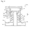
Fig. 3 is a cross-sectional view showing another example of the manhole portion of the transport container for a liquefied gas shown inFig. 1 . - Hereinafter, a transport container for a liquefied gas according to an embodiment is described by reference to drawings. In the respective drawings, identical or similar constitutional parts are given the same symbols. To avoid the following descriptions from being unnecessarily redundant thus allowing those who are skilled in the art to easily understand them, the detailed description with respect to matters which have been already well-known and the repeated description with respect to the substantially same constitutions may be omitted. The following descriptions and attached drawings are not intended to restrict the subject matters described in Claims.
- As the transport container for a liquefied gas of the embodiment described hereinafter, a transport container for a liquefied gas mounted on a liquefied gas carrying vessel for domestic sea routes which carries a liquefied gas carried from a foreign country to ports in Japan is taken as an example. However, it is not intended that the transport container for a liquefied gas is limited to such the container.
- Firstly, the background of development of the transport container for a liquefied gas according to this embodiment is described.
- In the case of transporting the LNG, with respect to a transport container for a liquefied gas mounted on a liquefied gas carrying vessel, heat input to the LNG from the outside is suppressed by wrapping a heat insulation material on an outer surface of a single shell tank in which the LNG is stored. It is mandatory by law to position a discharge port through which a liquefied gas is discharged from the tank at a place higher than a deck and hence, mounting of the discharge port on a bottom portion of the tank is not allowed, for example. Accordingly, it is necessary to mount a pump (submerged pump) on the bottom portion of the tank, which takes out the liquefied gas from the inside of the tank by pushing up the liquefied gas from the tank when unloading of the liquefied gas. On the other hand, it is mandatory by law to perform the maintenance and inspection of the submerged pump for every fixed period. To comply with such regulation, a manhole which allows an operator to go in and out from the tank is mounted on an upper portion of the tank.
- In such tank, when a liquefied gas to be transported by the tank is the LNG (liquefying temperature: -160°C), the heat insulation material which shields heat input to the tank is made of, for example, urethane, phenolic foam or the like which contains air layers. Further, the heat insulation material is cooled by liquid nitrogen.
- On the other hand, in a case where a liquefied gas to be transported is liquefied hydrogen (liquefying temperature: -250°C), a boiling point of liquefied hydrogen is lower than a condensing temperature of air and hence, when the above-mentioned heat insulation material is used, the air contained in the heat insulation material is changed into a liquid form and, then, is changed into a solid form. Accordingly, the heat insulation material which contains air completely loses a heat insulation effect. In view of such circumstances, there arises a necessity of forming a transport container into a double shell container constituted of an inner shell and an outer shell and adopting a vacuum heat insulation structure where a vacuum is created in a gap formed between the inner shell and the outer shell.
- A transport container for a liquefied gas mounted on a liquefied gas carrying vessel, which has the above vacuum heat insulation structure and includes the submerged pump and the manhole for the submerged pump as described above, has not existed conventionally. The transport container for a liquefied gas in this embodiment is the transport container satisfying such specification.
- The transport container for a liquefied gas is configured such that the container includes a cylindrical barrel portion, and both end portions of the barrel portion are closed by lids having an approximately semispherical shape respectively. As one example of outer sizes of the transport container for a liquefied gas, the transport container has a diameter of approximately 10 m and a length of approximately 25 m. Due to the restriction imposed on the manufacture brought about by such sizes, a gap formed between the inner shell and the outer shell is required to have a certain amount of width for providing the vacuum heat insulation structure. As a result, a volume of an inner-and-outer shells inter-space region, that is, a volume of the gap formed between the inner shell and the outer shell, becomes several hundreds cubic meter (m3). Accordingly, approximately one year is necessary to create a vacuum state providing the vacuum heat insulation in the inner-and-outer shells inter-space region with such a large volume.
- In view of the above, if the vacuum state created in the inner-and-outer shells inter-space region is to be opened to outside air each time the previously-mentioned inspection of the submerged pump stipulated by the regulation is performed, the container cannot be practically used as a transport container for a liquefied gas.
- To prevent the vacuum heat insulation region from having a large volume, a technique is considered where a volume to be opened to outside air is decreased by dividing the inner-and-outer shells inter-space region into a plurality of spaces. This technique, however, increases the number of metal contacts which are provided between the inner shell and the outer shell as zoning members, so that an amount of input heat to the tank by heat conduction is increased. There also arises a drawback that it is necessary to take into account for buffering a stress caused by a thermal shrinkage at fixing points of the metal contacts.
- The transport container for a liquefied gas of this embodiment has been developed in view of the above-mentioned background. The transport container for a liquefied gas of this embodiment is a transport container having the manhole structure where while maintaining the vacuum state created in the inner-and-outer shells inter-space region, a volume of a vacuum region which is opened in the work for performing the legal maintenance and inspection of the submerged pump disposed in the inside of the transport container for a liquefied gas is minimized, and heat input to the inner shell can be suppressed as much as possible.
- The transport container for a liquefied gas according to this embodiment having such constitution is described in detail hereinafter.
-
Fig. 1 shows a schematic structure of a transport container for a liquefiedgas 100 of this embodiment. The transport container for a liquefiedgas 100 is a container mounted on a liquefied gas carrying vessel and storing a liquefiedgas 1 having a boiling point lower than a condensing temperature of air therein. In this embodiment, liquefied hydrogen is taken as an example of the liquefiedgas 1. - The transport container for a
liquefied gas 100 includes: aninner shell 101 which stores theliquefied gas 1 therein; and anouter shell 102 which surrounds theinner shell 101. The transport container for a liquefiedgas 100 adopts the vacuum heat insulation structure where an inner-and-outer shells inter-spaceregion 103 sandwiched between theinner shell 101 and theouter shell 102 is formed into a vacuum heat insulation layer. Theinner shell 101 is supported in the inside of theouter shell 102 by way of suspended rods or the like disposed in the inside of theouter shell 102. Air in the inner-and-outer shellsinter-space region 103 is evacuated by avacuum pump 106 disposed outside theouter shell 102. - The
inner shell 101 is configured such that theinner shell 101 includes a cylindrical barrel portion, and both end portions of the barrel portion are closed by lids having an approximately semispherical shape respectively. Theouter shell 102 surrounds theinner shell 101, and has the substantially same configuration as theinner shell 101. With respect to sizes of the transport container for a liquefiedgas 100, as one example of outer sizes of theouter shell 102, theouter shell 102 has a diameter of approximately 10 m and a length of approximately 25 m. - A submerged
pump 104 for handing the liquefiedgas 1 is mounted on abottom portion 101a in the inside of theinner shell 101 in thevertical direction 2. Atank dome 105 which constitutes a connecting portion between a pipe or the like connected to the submergedpump 104 and a machine or the like for handling the liquefiedgas 1, and amanhole 140 described below in detail are mounted on anupper portion 100a of the transport container for a liquefiedgas 100 in thevertical direction 2. - The
manhole 140 constitutes an exit and entrance port through which the outside of theouter shell 102 and the inside of theinner shell 101 are communicated with each other. As described above, themanhole 140 is a portion through which an operator goes in and out from theinner shell 101 in the work for performing the legal maintenance and inspection of the submergedpump 104. As shown inFig. 2 , themanhole 140 includes: aninner shell manhole 110 mounted on theinner shell 101; anouter shell manhole 120 mounted on theouter shell 102 in a state where theouter shell manhole 120 surrounds an outer side of theinner shell manhole 110; and a shieldingmember 130. - The
inner shell manhole 110 is constituted of: a cylindrical inner shellmanhole barrel portion 111 which is mounted on an upper portion of theinner shell 101 in an erected manner and through which the operator can goes in and out from theinner shell 101; aflange 112 which is welded to an upper end of the inner shellmanhole barrel portion 111; and ablind plate 113 which is detachably mounted on theflange 112 by means of bolts. The exit and entrance port of the inner shellmanhole barrel portion 111 is usually closed by theblind plate 113, and theblind plate 113 is removed only when it is necessary to perform the maintenance and inspection of the submergedpump 104. - The
outer shell manhole 120 includes: a cylindrical outer shellmanhole barrel portion 121 which is mounted on an upper portion of theouter shell 102 in an erected manner; aflange 122 which is welded to an upper end portion of the outer shellmanhole barrel portion 121; ablind plate 123 which is detachably mounted on theflange 122 by means of bolts; and avacuum port 124 which constitutes a connecting portion connected with thevacuum pump 106. As described above, theouter shell manhole 120 surrounds an outer side of theinner shell manhole 110 and hence, all members of theinner shell manhole 110 including theblind plate 113 are positioned inside the outer shellmanhole barrel portion 121. The exit and entrance port of the outer shellmanhole barrel portion 121 is also usually closed by theblind plate 123 of theouter shell manhole 120, and theblind plate 123 is removed only when it is necessary to perform the maintenance and inspection of the submergedpump 104. - The shielding
member 130 is a flexible member having the following configuration. That is, the shieldingmember 130 is disposed between an outer surface of the inner shellmanhole barrel portion 111 of theinner shell manhole 110 and an inner surface of the outer shellmanhole barrel portion 121 of theouter shell manhole 120. When theouter shell manhole 120 is opened, the shieldingmember 130 separates the inner-and-outer shellsinter-space region 103 which is set in a vacuum state and outside air from each other, and suppresses heat input to theinner shell manhole 110 from theouter shell manhole 120 by heat conduction. - The shielding
member 130 has: oneend 131 which is fixed to the outer surface of the inner shellmanhole barrel portion 111; theother end 132 which is fixed to the inner surface of the outer shellmanhole barrel portion 121; and a connectingportion 133 which extends between the oneend 131 and theother end 132 and has at least onebent portion 133a. The shieldingmember 130 has a plate thickness t2 smaller than a plate thickness t1 of members for forming the outer shellmanhole barrel portion 121 and the inner shellmanhole barrel portion 111. In this embodiment, the shieldingmember 130 is formed of a bellows. -
Fig. 2 and the like show an example of the shieldingmember 130 where thebent portion 133a has a U-shape, and respective connectingportions 133 which are connected to thebent portion 133a are arranged parallel to each other. However, a shape of thebent portion 133a is not limited to the U-shape. For example, thebent portion 133a may have a V-shape, and the respective connectingportions 133 which are connected to thebent portion 133a may not be arranged parallel to each other. - In this embodiment, as shown in
Fig. 2 , a doublingplate 126 is provided at a joint portion between theouter shell 102 and theouter shell manhole 120. The doublingplate 126 is provided for facilitating the mounting of theouter shell manhole 120 on theouter shell 102 and for shielding radiant heat which intends to directly intrude theinner shell 101 from the shieldingmember 130 along thevertical direction 2. Accordingly, as shown inFig. 2 , an opening is formed in the doublingplate 126 to an extent that a sufficient region of the doublingplate 126 which faces the connectingportion 133 of the shieldingmember 130 in thevertical direction 2 exists. - As described above, by arranging the whole
inner shell manhole 110 in the inside of the outer shellmanhole barrel portion 121 and by disposing the shieldingmember 130 between the inner shellmanhole barrel portion 111 and the outer shellmanhole barrel portion 121, theblind plate 113 of theinner shell manhole 110 and theblind plate 123 of theouter shell manhole 120 are positioned above the shieldingmember 130 in thevertical direction 2. Accordingly, a region where a pressure becomes an atmospheric pressure by removing theblind plate 123 of theouter shell manhole 120 when the maintenance and inspection of the submergedpump 104 is performed becomes only an atmospheric pressureopen region 125 ranging from theblind plate 123 of theouter shell manhole 120 to the shieldingmember 130. Accordingly, the inner-and-outer shellsinter-space region 103 can be maintained in the vacuum state. The atmospheric pressureopen region 125 is brought into a vacuum state by thevacuum pump 106 through thevacuum port 124 formed in theouter shell manhole 120 after mounting theblind plate 113 and theblind plate 123. - As another function of the shielding
member 130, the shieldingmember 130 suppresses heat input to the liquefiedgas 1 stored in theinner shell manhole 110, that is, in theinner shell 101. As described by the followingformula 1, an amount of heat input can be controlled based on a material of the shieldingmember 130, and a length and a plate thickness of the connectingportion 133.
- Here, Q denotes a total heat input amount (W) during a transport period of a liquefied gas, λ denotes a thermal conductivity (W/mK) of the material of the shielding
member 130, L denotes a total length (mm) of the connectingportion 133, A denotes a cross-sectional area (mm2) of the connectingportion 133, and ΔT denotes a temperature gradient (K). - In this manner, the shielding
member 130 used in the transport container for a liquefiedgas 100 can be designed corresponding to a permissible amount of heat input to the liquefiedgas 1 stored in theinner shell manhole 110, that is, in theinner shell 101 from the outside and hence, the degree of freedom in designing the shieldingmember 130 can be increased. On the other hand, it is also possible to control an amount of heat input by designing the shieldingmember 130. - The length of the connecting
portion 133 is used as one of parameters relating to the amount of heat input. AlthoughFig. 2 shows an example where the shieldingmember 130 includes a singlebent portion 133a, the shieldingmember 130 may include a plurality ofbent portions 133a so as to increase the length of the connectingportion 133. Further, thebent portion 133a may be formed of a folded back portion. - That is, by forming the shielding
member 130 using a flexible member, a heat transfer distance between theouter shell manhole 120 and theinner shell manhole 110 can be increased and hence, the amount of heat input to the inside of the transport container for a liquefied gas from the outside can be decreased. - As one example of the shielding
member 130, assuming that the amount of heat input Q is 2W, when the material for forming the shieldingmember 130 is stainless steel, the total length L of the connectingportion 133 is at least approximately 1.6 m when the plate thickness t of the connectingportion 133 is 0.5 mm, and the total length L of the connectingportion 133 is at least approximately 3.3 m when the plate thickness t of the connectingportion 133 is 1 mm. -
Fig. 2 illustrates the example where the connectingportion 133 is arranged with thebent portion 133a oriented downward in thevertical direction 2. However, the manner of arrangement of the connectingportion 133 is not limited to the above, and the connectingportion 133 may be arranged with thebent portion 133a oriented upward. - From a viewpoint of facilitating the manufacture of the
manhole 140, as shown inFig. 2 , it is preferable that oneend 131 and theother end 132 of the shieldingmember 130 are arranged at the same level in thevertical direction 2. However, the manner of arrangement of the shieldingmember 130 is not limited to the above. As shown inFig. 3 , oneend 131 and theother end 132 of the shieldingmember 130 may be arranged at different levels in thevertical direction 2. - In short, it is sufficient that the shielding
member 130 is designed in conformity with the above-mentionedformula 1, and the number ofbent portions 133a, the orientation of thebent portion 133a, a shape of the shieldingmember 130 and the like are not limited. However, as shown in theformula 1, the amount of heat input is proportional to the thermal conductivity of the shieldingmember 130. Accordingly, by using a material with the thermal conductivity as small as possible, the total length of the connectingportion 133 can be decreased, so that it is possible to suppress an unnecessary increase especially in height of themanhole 140. - Further, the shielding
member 130 has at least onebent portion 133a and hence, the shieldingmember 130 has flexibility. Accordingly, the shieldingmember 130 can absorb the displacement caused by the thermal shrinkage of theinner shell 101 and the thermal shrinkage of theouter shell 102 as well as the displacement caused by shaking of theinner shell 101 and theouter shell 102. The displacement of theinner shell 101 and theouter shell 102 can be absorbed by the shieldingmember 130 in this manner and hence, it is possible to enhance the degree of freedom in designing the support structure of theinner shell 101 with respect to theouter shell 102. - Next, the liquefied gas transport operation by the transport container for a liquefied
gas 100 having the above-mentioned constitution will be described. - Before the liquefied
gas 1 to be transported is poured into theinner shell 101, air in the inner-and-outer shellsinter-space region 103 defined between theinner shell 101 and theouter shell 102 is evacuated by thevacuum pump 106 disposed outside theouter shell 102 so that the inner-and-outer shellsinter-space region 103 is brought into a vacuum state. At this stage of operation, in themanhole 140, outside air and the inner-and-outer shellsinter-space region 103 are shielded and separated from each other by the shieldingmember 130. Usually, theblind plate 113 is mounted on theinner shell manhole 110 and theblind plate 123 is mounted on theouter shell manhole 120. Accordingly, air in the atmospheric pressureopen region 125 is also evacuated by thevacuum pump 106 through thevacuum port 124 in theouter shell manhole 120 so that the atmospheric pressureopen region 125 is also brought into a vacuum state. - In a state where at least the inner-and-outer shells
inter-space region 103 is brought into the vacuum state, the liquefiedgas 1 to be transported is poured into the inside of theinner shell 101 from the outside through thetank dome 105. After pouring the liquefiedgas 1 into the inside of theinner shell 101, the liquefiedgas 1 is transported to a destination port by the liquefied gas carrying vessel. - During the transport period, at the place of the
manhole 140, heat is intruded into theinner shell manhole 110, theinner shell 101, and lastly the liquefiedgas 1 from theouter shell manhole 120 through the shieldingmember 130. In this case, however, an amount of heat input is less than or equal to an allowable amount set by designing, so that the amount of heat input is not an amount which affects an evaporation loss of the loaded liquefiedgas 1. Further, the shieldingmember 130 can absorb the relative displacement between theinner shell 101 and theouter shell 102 which may be caused by the thermal shrinkage, the shaking and the like during the transport. - After the liquefied gas carrying vessel arrives at the destination port, the liquefied
gas 1 is unloaded through thetank dome 105 by the submergedpump 104 disposed in the inside of theinner shell 101. - On the other hand, in the maintenance and inspection of the submerged
pump 104, all liquefiedgas 1 in theinner shell 101 is discharged, and the inside of theinner shell 101 is replaced with air through thetank dome 105. As subsequent steps, firstly, the atmospheric pressureopen region 125 is opened to outside air through thevacuum port 124 or by removing theblind plate 123 of theouter shell manhole 120. At this stage of operation, as has been described previously, the inner-and-outer shellsinter-space region 103 is maintained in the vacuum state by the shieldingmember 130. - Next, the
blind plate 113 of theinner shell manhole 110 is removed. Then, the operator can enter into the inside of theinner shell 101 through the opening at theflange 122 of theouter shell manhole 120 and the opening at theflange 112 of theinner shell manhole 110. - After the maintenance and inspection of the submerged
pump 104 is completed, theblind plate 113 of theinner shell manhole 110 and theblind plate 123 of theouter shell manhole 120 are sequentially fastened to theflange 112 and theflange 122 respectively. Then, air in the atmospheric pressureopen region 125 is evacuated by thevacuum pump 106 through thevacuum port 124 so that the atmospheric pressureopen region 125 is brought into the vacuum state. The volume of the atmospheric pressureopen region 125 is extremely small compared with the volume of the inner-and-outer shellsinter-space region 103 and hence, the atmospheric pressureopen region 125 can be returned to the vacuum state within a short time. - As described above, according to the transport container for a liquefied
gas 100 of this embodiment, the transport container for a liquefiedgas 100 can be used again in service after a lapse of the short time from the maintenance and inspection of the submergedpump 104. - In the description made heretofore, a method which uses the submerged
pump 104 is described as the method of unloading the liquefiedgas 1. However, the transport container for a liquefiedgas 100 of this embodiment can unload the liquefied gas by a self-pressurization way without using the submergedpump 104 or by the combination of the self-pressurization way and the submergedpump 104. Here, the self-pressurization way means a method for unloading the liquefiedgas 1 by increasing a pressure of the inside of theinner shell 101 by forcibly heating the liquefiedgas 1 within theinner shell 101 from the outside and then evaporating it. - It is to be noted that, by properly combining the arbitrary modifications in the aforementioned embodiment, the effects possessed by them can be produced.
- Although the present invention has been sufficiently described in conjunction with the preferred embodiment by reference to attached drawings, it is apparent that various modifications and variations are conceivable to those who are skilled in the art. It should be construed that such modifications and variations are included within the scope of the present invention described in attached Claims unless they depart therefrom.
- Further, Japanese Patent Application No.
2012-276563 filed on December 19, 2012 - The present invention is applicable to a transport container for a liquefied gas, specifically to a transport container for a liquefied gas used for marine transport of a liquefied gas.
-
- 1: liquefied gas
- 2: vertical direction
- 100: transport container for a liquefied gas
- 100a: upper portion
- 101: inner shell
- 101a: bottom portion
- 102: outer shell
- 103: inner-and-outer shells inter-space region
- 104: submerged pump
- 110: inner shell manhole
- 111: inner shell manhole barrel portion
- 120: outer shell manhole
- 121: outer shell manhole barrel portion
- 130: shielding member
- 131: one end
- 132: the other end
- 133: connecting portion
- 133a: bent portion
- 140: manhole
Claims (5)
- A transport container for a liquefied gas mounted on a liquefied gas carrying vessel and storing the liquefied gas having a boiling point lower than a condensing temperature of air therein, the transport container for a liquefied gas comprising:an inner shell configured to store the liquefied gas therein;an outer shell configured to surround the inner shell;an inner-and-outer shells inter-space region configured to constitute a vacuum heat insulation layer formed between the inner shell and the outer shell;a submerged pump fixed to a bottom portion within the inner shell in a vertical direction and configured to discharge the liquefied gas to the outside of the outer shell; anda manhole for maintenance and inspection of the submerged pump, the manhole mounted on an upper portion of the transport container for a liquefied gas in the vertical direction, and configured to make the outside of the outer shell and the inside of the inner shell communicate with each other.
- The transport container for a liquefied gas according to claim 1, wherein the manhole includes a shielding member configured to separate the inner-and-outer shells inter-space region and outside air from each other at the time of opening the manhole, and suppress a heat input to the inner shell from the outer shell.
- The transport container for a liquefied gas according to claim 2, wherein
the manhole includes:an inner shell manhole mounted on an upper portion of the inner shell in the vertical direction, andan outer shell manhole surrounding an outer side of the inner shell manhole and mounted on an upper portion of the outer shell in the vertical direction, andthe shielding member is a flexible member and is disposed between an inner shell manhole barrel portion of the inner shell manhole and an outer shell manhole barrel portion of the outer shell manhole. - The transport container for a liquefied gas according to claim 3, wherein
the shielding member has: one end fixed to the inner shell manhole barrel portion; the other end fixed to the outer shell manhole barrel portion; and a connecting portion extending between the one end and the other end and having at least one bent portion, the shielding member having a plate thickness smaller than plate thicknesses of members for forming the outer shell manhole barrel portion and the inner shell manhole barrel portion respectively. - The transport container for a liquefied gas according to any one of claims 2 to 4, wherein
the shielding member is configured to be designed using a following formula,
wherein Q denotes a total heat input amount (W) during a transport period of a liquefied gas, λ denotes a thermal conductivity (W/mK) of a material for forming the shielding member, L denotes a total length (mm) of the connecting portion, A denotes a cross-sectional area (mm2) of the connecting portion, and ΔT denotes a temperature gradient (K).
Applications Claiming Priority (2)
| Application Number | Priority Date | Filing Date | Title |
|---|---|---|---|
| JP2012276563A JP2014118206A (en) | 2012-12-19 | 2012-12-19 | Liquefied gas transport container |
| PCT/JP2013/083418 WO2014097974A1 (en) | 2012-12-19 | 2013-12-13 | Transport container for liquefied gas |
Publications (2)
| Publication Number | Publication Date |
|---|---|
| EP2937297A1 true EP2937297A1 (en) | 2015-10-28 |
| EP2937297A4 EP2937297A4 (en) | 2016-08-31 |
Family
ID=50978308
Family Applications (1)
| Application Number | Title | Priority Date | Filing Date |
|---|---|---|---|
| EP13864923.1A Withdrawn EP2937297A4 (en) | 2012-12-19 | 2013-12-13 | Transport container for liquefied gas |
Country Status (6)
| Country | Link |
|---|---|
| EP (1) | EP2937297A4 (en) |
| JP (1) | JP2014118206A (en) |
| KR (1) | KR20150059783A (en) |
| CN (1) | CN104870338B (en) |
| BR (1) | BR112015014148A2 (en) |
| WO (1) | WO2014097974A1 (en) |
Cited By (6)
| Publication number | Priority date | Publication date | Assignee | Title |
|---|---|---|---|---|
| EP3012508A4 (en) * | 2013-06-19 | 2017-03-29 | Kawasaki Jukogyo Kabushiki Kaisha | Double-shelled tank and liquefied gas transport vessel |
| EP3760910A4 (en) * | 2018-03-02 | 2021-11-24 | Kawasaki Jukogyo Kabushiki Kaisha | DOUBLE ENCLOSURE TANK AND LIQUEFIED GAS CARRIER |
| EP4095429A1 (en) * | 2021-05-27 | 2022-11-30 | Cryolor Société Anonyme | Cryogenic container |
| RU226725U1 (en) * | 2024-03-14 | 2024-06-19 | Денис Александрович Карлов | TANK TRUCK FOR SPECIAL OPERATIONS |
| EP4471322A1 (en) * | 2023-05-31 | 2024-12-04 | Airbus Operations GmbH | Cryogenic tank with access opening, and aircraft equipped therewith |
| EP4517152A1 (en) * | 2023-09-01 | 2025-03-05 | Airbus Operations Limited | Storage tank arrangement |
Families Citing this family (14)
| Publication number | Priority date | Publication date | Assignee | Title |
|---|---|---|---|---|
| JP6134211B2 (en) * | 2013-06-19 | 2017-05-24 | 川崎重工業株式会社 | Double shell tank and liquefied gas carrier |
| KR101865210B1 (en) * | 2013-06-21 | 2018-06-07 | 카와사키 주코교 카부시키 카이샤 | Liquefied gas-storing tank and liquefied gas transport vessel |
| KR101607828B1 (en) | 2014-11-20 | 2016-03-31 | 삼성중공업 주식회사 | Double-Walled Tank |
| WO2016121098A1 (en) * | 2015-01-30 | 2016-08-04 | 入江工研株式会社 | Metal sealing component, metal sealing structure and method for manufacturing metal sealing component |
| WO2017018699A1 (en) * | 2015-07-27 | 2017-02-02 | 강희자 | Cryogenic liquid storage tank |
| WO2017042424A1 (en) | 2015-09-11 | 2017-03-16 | Wärtsilä Finland Oy | A fuel tank arrangement of a marine vessel |
| KR101756833B1 (en) | 2015-12-01 | 2017-07-12 | 에스티엑스조선해양 주식회사 | Strainer for gas dome of lng cargo tank and gas dome with the same |
| WO2017114880A1 (en) * | 2015-12-30 | 2017-07-06 | Arranged Bvba | Duplex constructive pressure vessel element |
| CN106764401A (en) * | 2017-02-24 | 2017-05-31 | 江苏宏博机械制造有限公司 | A kind of lightweight high intensity pressure resistant type pressure pan |
| CN109268674B (en) * | 2017-07-18 | 2024-10-01 | 张家港中集圣达因低温装备有限公司 | Low temperature and normal pressure storage tank and its manhole structure |
| CN110056761B (en) * | 2018-01-19 | 2024-06-04 | 张家港中集圣达因低温装备有限公司 | Manhole device and vacuum insulated cryogenic storage tank having the manhole device |
| JP7071168B2 (en) * | 2018-03-07 | 2022-05-18 | 川崎重工業株式会社 | Liquefied gas tank |
| JP7273508B2 (en) * | 2018-12-28 | 2023-05-15 | 川崎重工業株式会社 | vessel |
| WO2023229008A1 (en) * | 2022-05-27 | 2023-11-30 | 川崎重工業株式会社 | Manhole structure, multiple-wall tank, and marine vessel |
Family Cites Families (14)
| Publication number | Priority date | Publication date | Assignee | Title |
|---|---|---|---|---|
| US1978608A (en) * | 1933-06-21 | 1934-10-30 | Smith Corp A O | Welded nozzle for jacketed vessels |
| JPS4927620B1 (en) * | 1970-09-30 | 1974-07-19 | ||
| JPS5114330Y2 (en) * | 1971-12-01 | 1976-04-16 | ||
| JPS4889411A (en) * | 1972-03-01 | 1973-11-22 | ||
| JPS5649035Y2 (en) * | 1977-11-08 | 1981-11-16 | ||
| JPS60245899A (en) * | 1984-05-21 | 1985-12-05 | Hitachi Ltd | Insulating support device for cryogenic containers |
| JPS6119592U (en) * | 1984-07-09 | 1986-02-04 | 石川島播磨重工業株式会社 | Manhole structure of double shell tank |
| JPS62147800U (en) * | 1986-03-12 | 1987-09-18 | ||
| JPS639600U (en) * | 1986-07-08 | 1988-01-22 | ||
| JPH0717920Y2 (en) * | 1990-03-09 | 1995-04-26 | 株式会社石井鐵工所 | Double-shell tank pump barrel support device |
| JPH08159391A (en) * | 1994-12-06 | 1996-06-21 | Ishikawajima Harima Heavy Ind Co Ltd | Liquid hydrogen storage facility and its insulation method |
| CN1333198C (en) * | 2004-04-15 | 2007-08-22 | 中国国际海运集装箱(集团)股份有限公司 | High vacuum heat insulation low temperature liquefied gas storage tank |
| DE102010018301A1 (en) * | 2010-04-23 | 2011-10-27 | Lurgi Gmbh | Inspection nozzle arrangement for e.g. double shell container, has first connecting piece extending in second connecting piece, and where first connecting piece is not mechanically linked with outer shell or second connecting piece |
| JP5670225B2 (en) | 2011-03-03 | 2015-02-18 | 川崎重工業株式会社 | Tank dome flange structure |
-
2012
- 2012-12-19 JP JP2012276563A patent/JP2014118206A/en active Pending
-
2013
- 2013-12-13 CN CN201380066716.5A patent/CN104870338B/en not_active Expired - Fee Related
- 2013-12-13 WO PCT/JP2013/083418 patent/WO2014097974A1/en not_active Ceased
- 2013-12-13 EP EP13864923.1A patent/EP2937297A4/en not_active Withdrawn
- 2013-12-13 BR BR112015014148A patent/BR112015014148A2/en not_active IP Right Cessation
- 2013-12-13 KR KR1020157010446A patent/KR20150059783A/en not_active Ceased
Cited By (8)
| Publication number | Priority date | Publication date | Assignee | Title |
|---|---|---|---|---|
| EP3012508A4 (en) * | 2013-06-19 | 2017-03-29 | Kawasaki Jukogyo Kabushiki Kaisha | Double-shelled tank and liquefied gas transport vessel |
| EP3760910A4 (en) * | 2018-03-02 | 2021-11-24 | Kawasaki Jukogyo Kabushiki Kaisha | DOUBLE ENCLOSURE TANK AND LIQUEFIED GAS CARRIER |
| EP4095429A1 (en) * | 2021-05-27 | 2022-11-30 | Cryolor Société Anonyme | Cryogenic container |
| FR3123410A1 (en) * | 2021-05-27 | 2022-12-02 | Cryolor | Cryogenic container |
| EP4471322A1 (en) * | 2023-05-31 | 2024-12-04 | Airbus Operations GmbH | Cryogenic tank with access opening, and aircraft equipped therewith |
| EP4517152A1 (en) * | 2023-09-01 | 2025-03-05 | Airbus Operations Limited | Storage tank arrangement |
| RU226725U1 (en) * | 2024-03-14 | 2024-06-19 | Денис Александрович Карлов | TANK TRUCK FOR SPECIAL OPERATIONS |
| RU233066U1 (en) * | 2024-11-08 | 2025-04-02 | Денис Александрович Карлов | FUEL TANKER FOR GROUP REFUELING OF EQUIPMENT |
Also Published As
| Publication number | Publication date |
|---|---|
| BR112015014148A2 (en) | 2017-07-11 |
| CN104870338B (en) | 2017-03-08 |
| CN104870338A (en) | 2015-08-26 |
| EP2937297A4 (en) | 2016-08-31 |
| WO2014097974A1 (en) | 2014-06-26 |
| KR20150059783A (en) | 2015-06-02 |
| JP2014118206A (en) | 2014-06-30 |
Similar Documents
| Publication | Publication Date | Title |
|---|---|---|
| KR20150059783A (en) | Transport container for liquefied gas | |
| CN105264279B (en) | Double-shelled storage tank and liquid gas carry vessel | |
| EP3904196B1 (en) | Ship | |
| CN105308381B (en) | Liquid gas keeps tank and liquid gas carry vessel | |
| CN111771080B (en) | Container for storing and transporting liquefied gases | |
| JP5153416B2 (en) | Ship | |
| US10882680B2 (en) | Container for both cryopreservation and transportation | |
| KR20090132225A (en) | LNG storage tanks and LAN vessels equipped with the same | |
| KR102633981B1 (en) | Tank | |
| US3313116A (en) | Method for cooling and filling liquefied gas transport and storage tanks | |
| KR102782464B1 (en) | shipping | |
| US20170159883A1 (en) | Cryogenic tank and method of storing cryogenic liquids | |
| CN115552166B (en) | Liquid dome comprising a liquefied gas storage tank provided with an opening with an additional cover | |
| KR20160148309A (en) | Collecting apparatus of leakage for liquid gas storage tank and marine structure including the same | |
| KR20140004166U (en) | Collecting Device Of Leak For Independent Type Cargo Tank | |
| KR101625639B1 (en) | Super low temperature liquid storage structure | |
| CN115244329B (en) | Dual access hatch covers for liquefied gas transport tanks | |
| RU2513152C2 (en) | Heat insulation of tank for transportation of liquefied natural gas | |
| KR20140040533A (en) | Structure for collecting liquefied natural gas | |
| US10711945B2 (en) | Transport container | |
| EP3628386B1 (en) | Enclosure for distillation column | |
| CN110745385B (en) | Space material low-temperature transportation device and material loading method | |
| JPH07232695A (en) | Liquid hydrogen tanker | |
| RU2318156C1 (en) | Heat insulated cryogenic tank | |
| KR102779533B1 (en) | Leakage liquid collection apparatus for lng cargo tank and offshore structure including the same |
Legal Events
| Date | Code | Title | Description |
|---|---|---|---|
| PUAI | Public reference made under article 153(3) epc to a published international application that has entered the european phase |
Free format text: ORIGINAL CODE: 0009012 |
|
| 17P | Request for examination filed |
Effective date: 20150617 |
|
| AK | Designated contracting states |
Kind code of ref document: A1 Designated state(s): AL AT BE BG CH CY CZ DE DK EE ES FI FR GB GR HR HU IE IS IT LI LT LU LV MC MK MT NL NO PL PT RO RS SE SI SK SM TR |
|
| AX | Request for extension of the european patent |
Extension state: BA ME |
|
| DAX | Request for extension of the european patent (deleted) | ||
| A4 | Supplementary search report drawn up and despatched |
Effective date: 20160803 |
|
| RIC1 | Information provided on ipc code assigned before grant |
Ipc: F17C 13/06 20060101ALI20160728BHEP Ipc: F17C 13/02 20060101ALI20160728BHEP Ipc: B65D 90/10 20060101AFI20160728BHEP Ipc: B65D 88/06 20060101ALI20160728BHEP |
|
| STAA | Information on the status of an ep patent application or granted ep patent |
Free format text: STATUS: THE APPLICATION HAS BEEN WITHDRAWN |
|
| 18W | Application withdrawn |
Effective date: 20171205 |