EP2937275A1 - System for detecting tensile force of guy rope in pneumatic fender and pneumatic fender - Google Patents
System for detecting tensile force of guy rope in pneumatic fender and pneumatic fender Download PDFInfo
- Publication number
- EP2937275A1 EP2937275A1 EP13865491.8A EP13865491A EP2937275A1 EP 2937275 A1 EP2937275 A1 EP 2937275A1 EP 13865491 A EP13865491 A EP 13865491A EP 2937275 A1 EP2937275 A1 EP 2937275A1
- Authority
- EP
- European Patent Office
- Prior art keywords
- tensile force
- guy rope
- pneumatic fender
- fender
- guy
- Prior art date
- Legal status (The legal status is an assumption and is not a legal conclusion. Google has not performed a legal analysis and makes no representation as to the accuracy of the status listed.)
- Granted
Links
Images
Classifications
-
- G—PHYSICS
- G08—SIGNALLING
- G08B—SIGNALLING SYSTEMS, e.g. PERSONAL CALLING SYSTEMS; ORDER TELEGRAPHS; ALARM SYSTEMS
- G08B21/00—Alarms responsive to a single specified undesired or abnormal condition and not otherwise provided for
- G08B21/18—Status alarms
- G08B21/182—Level alarms, e.g. alarms responsive to variables exceeding a threshold
-
- G—PHYSICS
- G01—MEASURING; TESTING
- G01L—MEASURING FORCE, STRESS, TORQUE, WORK, MECHANICAL POWER, MECHANICAL EFFICIENCY, OR FLUID PRESSURE
- G01L5/00—Apparatus for, or methods of, measuring force, work, mechanical power, or torque, specially adapted for specific purposes
- G01L5/04—Apparatus for, or methods of, measuring force, work, mechanical power, or torque, specially adapted for specific purposes for measuring tension in flexible members, e.g. ropes, cables, wires, threads, belts or bands
- G01L5/10—Apparatus for, or methods of, measuring force, work, mechanical power, or torque, specially adapted for specific purposes for measuring tension in flexible members, e.g. ropes, cables, wires, threads, belts or bands using electrical means
- G01L5/101—Apparatus for, or methods of, measuring force, work, mechanical power, or torque, specially adapted for specific purposes for measuring tension in flexible members, e.g. ropes, cables, wires, threads, belts or bands using electrical means using sensors inserted into the flexible member
-
- B—PERFORMING OPERATIONS; TRANSPORTING
- B63—SHIPS OR OTHER WATERBORNE VESSELS; RELATED EQUIPMENT
- B63B—SHIPS OR OTHER WATERBORNE VESSELS; EQUIPMENT FOR SHIPPING
- B63B59/00—Hull protection specially adapted for vessels; Cleaning devices specially adapted for vessels
- B63B59/02—Fenders integral with waterborne vessels or specially adapted therefor, e.g. fenders forming part of the hull or incorporated in the hull; Rubbing-strakes
-
- B—PERFORMING OPERATIONS; TRANSPORTING
- B63—SHIPS OR OTHER WATERBORNE VESSELS; RELATED EQUIPMENT
- B63B—SHIPS OR OTHER WATERBORNE VESSELS; EQUIPMENT FOR SHIPPING
- B63B59/00—Hull protection specially adapted for vessels; Cleaning devices specially adapted for vessels
- B63B59/02—Fenders integral with waterborne vessels or specially adapted therefor, e.g. fenders forming part of the hull or incorporated in the hull; Rubbing-strakes
- B63B2059/025—Fenders integral with waterborne vessels or specially adapted therefor, e.g. fenders forming part of the hull or incorporated in the hull; Rubbing-strakes pneumatic, e.g. inflatable
-
- E—FIXED CONSTRUCTIONS
- E02—HYDRAULIC ENGINEERING; FOUNDATIONS; SOIL SHIFTING
- E02B—HYDRAULIC ENGINEERING
- E02B3/00—Engineering works in connection with control or use of streams, rivers, coasts, or other marine sites; Sealings or joints for engineering works in general
- E02B3/20—Equipment for shipping on coasts, in harbours or on other fixed marine structures, e.g. bollards
- E02B3/26—Fenders
-
- Y—GENERAL TAGGING OF NEW TECHNOLOGICAL DEVELOPMENTS; GENERAL TAGGING OF CROSS-SECTIONAL TECHNOLOGIES SPANNING OVER SEVERAL SECTIONS OF THE IPC; TECHNICAL SUBJECTS COVERED BY FORMER USPC CROSS-REFERENCE ART COLLECTIONS [XRACs] AND DIGESTS
- Y02—TECHNOLOGIES OR APPLICATIONS FOR MITIGATION OR ADAPTATION AGAINST CLIMATE CHANGE
- Y02A—TECHNOLOGIES FOR ADAPTATION TO CLIMATE CHANGE
- Y02A30/00—Adapting or protecting infrastructure or their operation
- Y02A30/30—Adapting or protecting infrastructure or their operation in transportation, e.g. on roads, waterways or railways
Definitions
- the present invention relates to a system for detecting tensile force of a guy rope in a pneumatic fender and a pneumatic fender; in particular, a system for detecting tensile force of a guy rope in a pneumatic fender capable of preventing the breakage of the guy rope and a pneumatic fender.
- the pneumatic fender is installed in a quay in a port or on the side of a ship by being anchored with a guy rope (for example, refer to Patent Document 1).
- a pneumatic fender is installed between these ships.
- the tensile force generated in the guy rope varies during such an operation or when installing or removing the pneumatic fender.
- a guy rope able to sufficiently withstand the tensile force which it is assumed will be generated is selected as the guy rope to be used; however, breakages may occur due to the generation of excessive tensile forces at least equivalent to the assumed tensile force. When the guy rope breaks, extensive damage is caused, forcing interruptions to the operation or the like.
- Patent Document 1 Japanese Unexamined Patent Application Publication No. 2007-168749A
- An object of the present invention is to provide a system for detecting tensile force of a guy rope in a pneumatic fender capable of preventing breakage of the guy rope and a pneumatic fender.
- a system for detecting tensile force of a guy rope in a pneumatic fender of the present invention for achieving the object described above is provided with a tensile force sensor detecting tensile force of a guy rope anchoring a pneumatic fender, a wireless transmitter transmitting tensile force data detected by the tensile force sensor, a computation device to which tensile force data transmitted by the wireless transmitter is inputted, and an alerting device, in which the alerting device issues an alert when the inputted tensile force data is at least equivalent to reference data previously inputted to the computation device.
- a pneumatic fender of the present invention is provided with a fender main body, a bracket member interposed between the fender main body and a guy rope, a tensile force sensor attached to the bracket member to detect tensile force in the guy rope, and a wireless transmitter attached to the fender main body, in which tensile force data detected by the tensile force sensor is transmitted to a computation device which determines whether or not an excessive tensile force is generated based on the tensile force data.
- an alerting device issues an alert when tensile force data detected by the tensile force sensor is transmitted and inputted to a computation device by a wireless transmitter and is at least equivalent to reference data previously inputted to the computation device, thus it is possible to issue an alert before the guy rope breaks as long as the reference data is appropriately set.
- an alert is issued, it is possible to prevent breakage of the guy rope by carrying out a process which reduces the tensile force generated in the guy rope.
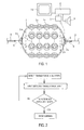
- a pneumatic fender 1 (below, fender 1) of the present invention as illustrated in FIG. 1 is provided with a fender main body 1a, bracket members (towing rings 3a) interposed between the fender main body 1a and guy ropes 2, tensile force sensors 5 detecting tensile force generated in the guy ropes 2, and a wireless transmitter 6.
- the fender main body 1a has rubber as the main material thereof and has bowl shaped mirror sections on both sides of a cylindrical section, and a fitting 1b is provided on at least one mirror section.
- a large number of protective members 4a connected with chains 4 are arranged on an outer peripheral surface of the fender main body 1a.
- the provision of the protective members 4a is optional; however, for example, tires or the like may be used. End sections of these chains 4 are connected with the towing rings 3a arranged on the mirror sections of the fender main body 1a.
- the tensile force sensors 5 are attached to bracket members interposed between the fender main body 1a and the guy ropes 2. In this embodiment, the tensile force sensors 5 are interposed between the guy ropes 2 and the towing rings 3a.
- the installation locations of the tensile force sensors 5 are not limited to these locations and installation is also possible on the towing rings 3a. It is possible to illustrate strain gauges as the tensile force sensors 5. According to the tensile force sensors 5, it is possible to detect tensile forces generated in the guy ropes 2 stably and with high accuracy.
- the wireless transmitter 6 is attached to an inner section of the fender main body 1a, for example, attached to the inner section of the fitting 1b or in the vicinity of the fitting 1b.
- Tensile force data T detected by the tensile force sensor 5 is transmitted and inputted to a computation device 8 by the wireless transmitter 6.
- the computation device 8 determines whether or not an excessive tensile force is generated based on the inputted tensile force data T. For this reason, reference data C which is a reference for determining whether or not an excessive tensile force is generated in the guy rope 2 is previously inputted to the computation device 8.
- the system for detecting tensile force of a guy rope of the present invention is configured of the tensile force sensor 5, the wireless transmitter 6, the computation device 8, and an alerting device 9.
- the alerting device 9 issues an alert when the tensile force data T inputted to the computation device 8 is at least equivalent to the previously inputted reference data C.
- a personal computer is used as the computation device 8.
- An alarm, an alert light, an alert wireless broadcast, or the like, or a combination of these are used as the alerting device 9.
- a monitor 10 connected with the computation device 8 is further provided. It is possible to optionally provide the monitor 10.
- the tensile force sensor 5 sequentially detects the tensile force generated in the guy rope 2.
- the tensile force data T detected by the tensile force sensor 5 is sequentially wirelessly transmitted by the wireless transmitter 6.
- the transmitted tensile force data T is inputted to the computation device 8 through a receiver 7.
- the computation device 8 sequentially determines whether or not an excessive tensile force is generated by comparing the inputted tensile force data T and the reference data C. The procedure for performing this determination is as illustrated in FIG. 2 .
- the value of the tensile force which the guy rope 2 is able to withstand in practice is set as a threshold.
- the detected tensile force data T the value of the tensile force
- the alerting device 9 immediately issues an alert. Since there is a potential for breakage in the guy rope 2 when an alert is issued by the alerting device 9, a process which reduces the tensile force generated in the guy rope 2 is carried out. According to this process, it is possible to prevent breakages in the guy rope 2.
- the reference data C is, for example, set based on the specifications of the guy rope 2. These specifications are the thickness, material, structure, and the like of the guy rope 2, and the reference data C is set based on at least one out of these specifications. For example, the thicker the guy rope 2, the greater the value of the tensile force set as the reference data C. Alternatively, the reference data C is set based on the usage frequency of the guy rope 2. That is, the greater the usage frequency of the guy rope 2, the greater the value of the tensile force set as the reference data C. In such a case, the usage frequency of each of the guy ropes 2 is recorded in the computation device 8. Alternatively, it is also possible to set the reference data C based on the thickness and the usage frequency of the guy rope 2. By setting the reference data C in this manner, it is possible to more reliably prevent breakages in the guy rope 2.
- the monitor 10 may, for example, sequentially display the tensile force data T and the reference data C inputted to the computation device 8. Due to this, it is possible to immediately grasp whether or not an excessive tensile force is generated by looking at the display on the monitor 10.
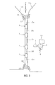
- a plurality of the fenders 1 are connected using guy ropes 2a, 2b, 2c, 2d, and 2e and arranged on the ship's sides.
- the receiver 7, the computation device 8, the alerting device 9, and the monitor 10 are, for example, installed in a control room in the ship 11a (11b).
- the computation device 8 determines that an excessive tensile force is generated in any of the guy ropes 2a to 2e and an alert is issued by the alerting device 9, for example, the interval between the two ships is narrowed by immediately tightening a ship mooring rope 12 which keeps the interval between the ships 11a and 11b. Due to this, the tensile force generated in the guy ropes 2a to 2e is reduced. Alternatively, the operation between the ships 11a and 11b is stopped. Due to this process, breakages are prevented in the guy ropes 2a to 2e.
Landscapes
- Chemical & Material Sciences (AREA)
- Physics & Mathematics (AREA)
- General Physics & Mathematics (AREA)
- Engineering & Computer Science (AREA)
- Ocean & Marine Engineering (AREA)
- Mechanical Engineering (AREA)
- Analytical Chemistry (AREA)
- Combustion & Propulsion (AREA)
- Business, Economics & Management (AREA)
- Emergency Management (AREA)
- General Engineering & Computer Science (AREA)
- Force Measurement Appropriate To Specific Purposes (AREA)
- Emergency Alarm Devices (AREA)
- Environmental & Geological Engineering (AREA)
- Civil Engineering (AREA)
- Structural Engineering (AREA)
- Arrangements For Transmission Of Measured Signals (AREA)
Abstract
Description
- The present invention relates to a system for detecting tensile force of a guy rope in a pneumatic fender and a pneumatic fender; in particular, a system for detecting tensile force of a guy rope in a pneumatic fender capable of preventing the breakage of the guy rope and a pneumatic fender.
- The pneumatic fender is installed in a quay in a port or on the side of a ship by being anchored with a guy rope (for example, refer to Patent Document 1). For example, when performing an operation of passing crude oil or the like between two ships at sea, a pneumatic fender is installed between these ships. The tensile force generated in the guy rope varies during such an operation or when installing or removing the pneumatic fender. A guy rope able to sufficiently withstand the tensile force which it is assumed will be generated is selected as the guy rope to be used; however, breakages may occur due to the generation of excessive tensile forces at least equivalent to the assumed tensile force. When the guy rope breaks, extensive damage is caused, forcing interruptions to the operation or the like.
- However, in the related art, there was no means for determining the tensile force generated in the guy rope with high accuracy. Therefore, it was necessary to take countermeasures to prevent breakage of the guy rope such as using an excessively thick guy rope set to a high safety factor.
- Patent Document 1: Japanese Unexamined Patent Application Publication No.
2007-168749A - An object of the present invention is to provide a system for detecting tensile force of a guy rope in a pneumatic fender capable of preventing breakage of the guy rope and a pneumatic fender.
- A system for detecting tensile force of a guy rope in a pneumatic fender of the present invention for achieving the object described above is provided with a tensile force sensor detecting tensile force of a guy rope anchoring a pneumatic fender, a wireless transmitter transmitting tensile force data detected by the tensile force sensor, a computation device to which tensile force data transmitted by the wireless transmitter is inputted, and an alerting device, in which the alerting device issues an alert when the inputted tensile force data is at least equivalent to reference data previously inputted to the computation device.
- In addition, a pneumatic fender of the present invention is provided with a fender main body, a bracket member interposed between the fender main body and a guy rope, a tensile force sensor attached to the bracket member to detect tensile force in the guy rope, and a wireless transmitter attached to the fender main body, in which tensile force data detected by the tensile force sensor is transmitted to a computation device which determines whether or not an excessive tensile force is generated based on the tensile force data.
- According to the present invention, it is possible to sequentially determine tensile force generated in a guy rope using a tensile force sensor detecting the tensile force in the guy rope. An alerting device issues an alert when tensile force data detected by the tensile force sensor is transmitted and inputted to a computation device by a wireless transmitter and is at least equivalent to reference data previously inputted to the computation device, thus it is possible to issue an alert before the guy rope breaks as long as the reference data is appropriately set. When an alert is issued, it is possible to prevent breakage of the guy rope by carrying out a process which reduces the tensile force generated in the guy rope.
-
- FIG. 1
- is an explanatory diagram illustrating a pneumatic fender and a system for detecting tensile force of a guy rope in a pneumatic fender of the present invention.
- FIG. 2
- is a flow chart illustrating a procedure for determining whether or not an excessive tensile force is generated.
- FIG. 3
- is an explanatory diagram illustrating an arrangement of the pneumatic fender of the present invention.
- Below, description will be given of the system for detecting tensile force of a guy rope in a pneumatic fender and the pneumatic fender of the present invention based on the embodiment illustrated in the diagram.
- A pneumatic fender 1 (below, fender 1) of the present invention as illustrated in
FIG. 1 is provided with a fendermain body 1a, bracket members (towing rings 3a) interposed between the fendermain body 1a andguy ropes 2,tensile force sensors 5 detecting tensile force generated in theguy ropes 2, and a wireless transmitter 6. - The fender
main body 1a has rubber as the main material thereof and has bowl shaped mirror sections on both sides of a cylindrical section, and a fitting 1b is provided on at least one mirror section. A large number ofprotective members 4a connected withchains 4 are arranged on an outer peripheral surface of the fendermain body 1a. The provision of theprotective members 4a is optional; however, for example, tires or the like may be used. End sections of thesechains 4 are connected with thetowing rings 3a arranged on the mirror sections of the fendermain body 1a. - The
tensile force sensors 5 are attached to bracket members interposed between the fendermain body 1a and the guy ropes 2. In this embodiment, thetensile force sensors 5 are interposed between theguy ropes 2 and thetowing rings 3a. The installation locations of thetensile force sensors 5 are not limited to these locations and installation is also possible on thetowing rings 3a. It is possible to illustrate strain gauges as thetensile force sensors 5. According to thetensile force sensors 5, it is possible to detect tensile forces generated in theguy ropes 2 stably and with high accuracy. - The wireless transmitter 6 is attached to an inner section of the fender
main body 1a, for example, attached to the inner section of thefitting 1b or in the vicinity of thefitting 1b. Tensile force data T detected by thetensile force sensor 5 is transmitted and inputted to acomputation device 8 by the wireless transmitter 6. Thecomputation device 8 determines whether or not an excessive tensile force is generated based on the inputted tensile force data T. For this reason, reference data C which is a reference for determining whether or not an excessive tensile force is generated in theguy rope 2 is previously inputted to thecomputation device 8. - The system for detecting tensile force of a guy rope of the present invention is configured of the
tensile force sensor 5, the wireless transmitter 6, thecomputation device 8, and analerting device 9. In the system, thealerting device 9 issues an alert when the tensile force data T inputted to thecomputation device 8 is at least equivalent to the previously inputted reference data C. - For example, a personal computer is used as the
computation device 8. An alarm, an alert light, an alert wireless broadcast, or the like, or a combination of these are used as thealerting device 9. - In this embodiment, a
monitor 10 connected with thecomputation device 8 is further provided. It is possible to optionally provide themonitor 10. - The
tensile force sensor 5 sequentially detects the tensile force generated in theguy rope 2. The tensile force data T detected by thetensile force sensor 5 is sequentially wirelessly transmitted by the wireless transmitter 6. The transmitted tensile force data T is inputted to thecomputation device 8 through areceiver 7. - The
computation device 8 sequentially determines whether or not an excessive tensile force is generated by comparing the inputted tensile force data T and the reference data C. The procedure for performing this determination is as illustrated inFIG. 2 . - As the reference data C, the value of the tensile force which the guy rope 2 is able to withstand in practice is set as a threshold. In a case where the detected tensile force data T (the value of the tensile force) reaches or exceeds the value of the tensile force set as the reference data C, it is determined that an excessive tensile force is generated. When it is determined that an excessive tensile force is generated, the
alerting device 9 immediately issues an alert. Since there is a potential for breakage in theguy rope 2 when an alert is issued by thealerting device 9, a process which reduces the tensile force generated in theguy rope 2 is carried out. According to this process, it is possible to prevent breakages in theguy rope 2. - Since it is possible to issue an alert before the guy rope 2 breaks as long as the reference data C is appropriately set in this manner, it is possible to reliably prevent breakages in the
guy rope 2. In addition, since it is possible to prevent breakages based on the tensile force generated in theguy rope 2, there is no need to use an over-engineered (for example, excessively thick) guy rope set to an excessively high safety factor in order to prevent breakages in theguy rope 2. - The reference data C is, for example, set based on the specifications of the
guy rope 2. These specifications are the thickness, material, structure, and the like of theguy rope 2, and the reference data C is set based on at least one out of these specifications. For example, the thicker the guy rope 2, the greater the value of the tensile force set as the reference data C. Alternatively, the reference data C is set based on the usage frequency of theguy rope 2. That is, the greater the usage frequency of theguy rope 2, the greater the value of the tensile force set as the reference data C. In such a case, the usage frequency of each of theguy ropes 2 is recorded in thecomputation device 8. Alternatively, it is also possible to set the reference data C based on the thickness and the usage frequency of theguy rope 2. By setting the reference data C in this manner, it is possible to more reliably prevent breakages in theguy rope 2. - The
monitor 10 may, for example, sequentially display the tensile force data T and the reference data C inputted to thecomputation device 8. Due to this, it is possible to immediately grasp whether or not an excessive tensile force is generated by looking at the display on themonitor 10. - In a case where an operation of transferring crude oil or the like between
ships FIG. 3 , a plurality of thefenders 1 are connected usingguy ropes receiver 7, thecomputation device 8, the alertingdevice 9, and themonitor 10 are, for example, installed in a control room in theship 11a (11b). - When the
computation device 8 determines that an excessive tensile force is generated in any of theguy ropes 2a to 2e and an alert is issued by the alertingdevice 9, for example, the interval between the two ships is narrowed by immediately tightening aship mooring rope 12 which keeps the interval between theships guy ropes 2a to 2e is reduced. Alternatively, the operation between theships guy ropes 2a to 2e. - In addition, in the case of this operation, an excessive tensile force is easily generated in the
guy rope 2a which is on the side (leading end side of theships guy rope 2a which is closest to the side in the direction F in which the waves are moving, the thickest out of all of theguy ropes -
- 1 Pneumatic fender
- 1a Fender main body
- 1b Fitting
- 2, 2a, 2b, 2c, 2d, 2e Guy rope
- 3a Towing ring
- 4 Chain
- 4a Protective member
- 5 Tensile force sensor
- 6 Wireless transmitter
- 7 Receiver
- 8 Computation device
- 9 Alerting device
- 10 Monitor
- 11a, 11b Ship
- 12 Ship mooring rope
Claims (5)
- A system for detecting tensile force of a guy rope in a pneumatic fender, the system comprising:a tensile force sensor detecting tensile force of a guy rope anchoring a pneumatic fender;a wireless transmitter transmitting tensile force data detected by the tensile force sensor;a computation device to which tensile force data transmitted by the wireless transmitter is inputted; andan alerting device;the alerting device issuing an alert when the inputted tensile force data is at least equivalent to reference data previously inputted to the computation device.
- The system for detecting tensile force of a guy rope in a pneumatic fender according to claim 1, wherein
the tensile force sensor is a strain gauge attached to a bracket member interposed between the guy rope and fender main body. - The system for detecting tensile force of a guy rope in a pneumatic fender according to claim 1 or 2, wherein
the reference data is set based on specifications of the guy rope. - The system for detecting tensile force of a guy rope in a pneumatic fender according to any one of claims 1 to 3, wherein
the reference data is set based on a usage frequency of the guy rope. - A pneumatic fender comprising:a fender main body;a bracket member interposed between the fender main body and a guy rope;a tensile force sensor attached to the bracket member to detect tensile force in the guy rope; anda wireless transmitter attached to the fender main body;tensile force data detected by the tensile force sensor being transmitted to a computation device which determines whether or not an excessive tensile force is generated based on the tensile force data.
Applications Claiming Priority (2)
| Application Number | Priority Date | Filing Date | Title |
|---|---|---|---|
| JP2012277992A JP5884719B2 (en) | 2012-12-20 | 2012-12-20 | Pneumatic fender guy rope tension detection system and pneumatic fender |
| PCT/JP2013/083593 WO2014098021A1 (en) | 2012-12-20 | 2013-12-16 | System for detecting tensile force of guy rope in pneumatic fender and pneumatic fender |
Publications (3)
| Publication Number | Publication Date |
|---|---|
| EP2937275A1 true EP2937275A1 (en) | 2015-10-28 |
| EP2937275A4 EP2937275A4 (en) | 2016-08-03 |
| EP2937275B1 EP2937275B1 (en) | 2018-09-05 |
Family
ID=50978351
Family Applications (1)
| Application Number | Title | Priority Date | Filing Date |
|---|---|---|---|
| EP13865491.8A Not-in-force EP2937275B1 (en) | 2012-12-20 | 2013-12-16 | System for detecting tensile force of guy rope in pneumatic fender and pneumatic fender |
Country Status (6)
| Country | Link |
|---|---|
| US (1) | US9460607B2 (en) |
| EP (1) | EP2937275B1 (en) |
| JP (1) | JP5884719B2 (en) |
| KR (1) | KR101739260B1 (en) |
| CN (1) | CN104822587A (en) |
| WO (1) | WO2014098021A1 (en) |
Families Citing this family (9)
| Publication number | Priority date | Publication date | Assignee | Title |
|---|---|---|---|---|
| JP6255965B2 (en) * | 2013-09-30 | 2018-01-10 | 横浜ゴム株式会社 | Vertical pneumatic fender and monitoring method thereof |
| US20150197408A1 (en) * | 2014-01-15 | 2015-07-16 | Slingmax, Inc. | Rope pre-failure warning indicator system and method |
| US9677238B1 (en) * | 2016-06-22 | 2017-06-13 | William Wei Lee | Pneumatic floating fender with a plastic protection cover |
| CN106800557B (en) * | 2016-12-05 | 2018-12-18 | 中节能万润股份有限公司 | A kind of dioxy phenoxazine thiophene analog derivative and its preparation method and application |
| JP7031122B2 (en) * | 2017-02-07 | 2022-03-08 | 横浜ゴム株式会社 | Pneumatic fender monitoring system |
| CN111566003B (en) * | 2017-11-13 | 2022-04-12 | 三星重工业株式会社 | Guard hanger device |
| CN113653011B (en) * | 2021-09-28 | 2022-11-25 | 江西省交通运输科学研究院有限公司 | Pier buffer stop |
| CN114045792B (en) * | 2021-11-19 | 2023-01-10 | 武汉理工大学 | Emergent protector of large-scale many cabins gasbag |
| KR20250165893A (en) | 2024-05-20 | 2025-11-27 | 탬프주식회사 | Pneumatic Fender Handling Equipment |
Family Cites Families (20)
| Publication number | Priority date | Publication date | Assignee | Title |
|---|---|---|---|---|
| US3871323A (en) * | 1973-08-31 | 1975-03-18 | Hydronautics | Close-coupled towing linkage |
| US5207171A (en) * | 1991-11-14 | 1993-05-04 | Westwood Iii Samuel M | Adjustable rope lock |
| GB9206409D0 (en) * | 1992-03-24 | 1992-05-06 | Knox John H | Alarm system |
| JP2779308B2 (en) * | 1993-07-06 | 1998-07-23 | 横浜ゴム株式会社 | Ship mooring monitoring system |
| JP3450410B2 (en) * | 1994-02-23 | 2003-09-22 | 東京瓦斯株式会社 | Mooring line tension monitoring system |
| JP2004219605A (en) * | 2003-01-14 | 2004-08-05 | Shozo Inoue | Wire rope with history display |
| FR2860632A1 (en) * | 2003-10-02 | 2005-04-08 | Kristell Electronique | Remote monitoring device for detecting e.g. risk of rupture of mooring rope of boat, has main block connected to sensors that measure tension in rope and trigger device to send signal to user when tension approaches threshold value |
| JP4678531B2 (en) * | 2004-10-07 | 2011-04-27 | 三菱電機株式会社 | Elevator rope tension adjustment device |
| JP4807067B2 (en) * | 2005-12-26 | 2011-11-02 | 横浜ゴム株式会社 | Pneumatic fender mooring device |
| CN2926041Y (en) * | 2006-06-27 | 2007-07-25 | 李存扣 | Movable bumping pad |
| EP2078669B1 (en) * | 2006-10-31 | 2015-06-17 | The Yokohama Rubber Co., Ltd. | Method and system for assisting steering/mooring of vessel |
| CN100423033C (en) * | 2006-12-14 | 2008-10-01 | 魏有平 | Electrical pole dragline monitoring and alarming system |
| CN200995770Y (en) * | 2007-02-07 | 2007-12-26 | 山东省科学院海洋仪器仪表研究所 | Sensor-chain distributor based on large buoy |
| US20090107384A1 (en) * | 2007-10-31 | 2009-04-30 | Stephenson Jr Samuel S | Fender System for Vessels Which Allows Fenders to Self Adjust |
| KR100936120B1 (en) * | 2007-12-26 | 2010-01-12 | 김종건 | Safety control system of crane using roller type load detector |
| CN201406013Y (en) * | 2009-03-09 | 2010-02-17 | 中国海洋石油总公司 | An offshore floating body with the function of positioning adjustment and anti-collision |
| US8087371B1 (en) * | 2009-09-25 | 2012-01-03 | The United States Of America As Represented By The Secretary Of The Navy | Deployable and inflatable fendering apparatus and method |
| US8567018B2 (en) * | 2009-12-24 | 2013-10-29 | Jeffery Dahl | Linkable rope assembly |
| CN203102525U (en) * | 2013-01-22 | 2013-07-31 | 长沙商贸旅游职业技术学院 | Bungee jumping rope safety detection alarm system device |
| CN103287553A (en) * | 2013-05-02 | 2013-09-11 | 大连理工大学 | Electromagnetic marine ball and its application method |
-
2012
- 2012-12-20 JP JP2012277992A patent/JP5884719B2/en not_active Expired - Fee Related
-
2013
- 2013-12-16 CN CN201380062782.5A patent/CN104822587A/en active Pending
- 2013-12-16 US US14/653,790 patent/US9460607B2/en not_active Expired - Fee Related
- 2013-12-16 WO PCT/JP2013/083593 patent/WO2014098021A1/en not_active Ceased
- 2013-12-16 EP EP13865491.8A patent/EP2937275B1/en not_active Not-in-force
- 2013-12-16 KR KR1020157015005A patent/KR101739260B1/en not_active Expired - Fee Related
Also Published As
| Publication number | Publication date |
|---|---|
| US20150325099A1 (en) | 2015-11-12 |
| WO2014098021A1 (en) | 2014-06-26 |
| US9460607B2 (en) | 2016-10-04 |
| KR101739260B1 (en) | 2017-05-24 |
| JP5884719B2 (en) | 2016-03-15 |
| KR20150083896A (en) | 2015-07-20 |
| EP2937275B1 (en) | 2018-09-05 |
| CN104822587A (en) | 2015-08-05 |
| JP2014121898A (en) | 2014-07-03 |
| EP2937275A4 (en) | 2016-08-03 |
Similar Documents
| Publication | Publication Date | Title |
|---|---|---|
| US9460607B2 (en) | System for detecting tensile force of guy rope in pneumatic fender and pneumatic fender | |
| AU2015321151B2 (en) | Broken link detection method for drag flight conveyor | |
| EP3889028B1 (en) | Mooring line monitoring system, mooring management system, mooring line monitoring method, and mooring management method | |
| US20150314997A1 (en) | Cable breakage diagnosis in a crane | |
| US11053648B2 (en) | Pneumatic fender monitoring system | |
| US10155569B2 (en) | Swivel for mooring arrangement having an electric power generator which converts relative rotation between two elements into electric power | |
| ES2785380T3 (en) | Drum transport facility with cable monitoring equipment | |
| WO2010118116A3 (en) | High tension cable measurement system and assembly | |
| EP3054054B1 (en) | Vertical pneumatic fender and monitoring method for same | |
| US20130279298A1 (en) | Monitoring of underwater mooring lines | |
| CN102383776A (en) | Drilling rig monitoring method, controller and system, and drilling rig | |
| KR20140067431A (en) | Apparatus for warning of tire defect | |
| JP3439835B2 (en) | Method and apparatus for automatically detecting internal pressure of pneumatic fenders | |
| MX2021009614A (en) | Monitoring and alerting systems for detecting hazardous conditions at loading docks. | |
| KR101735332B1 (en) | Mooring apparatus and system for measuring tension of mooring line | |
| WO2019076522A1 (en) | A smart line sensor | |
| JP2002211478A (en) | Mooring line monitoring device | |
| CN209411636U (en) | A kind of steel wire rope tension and deformation detecting device | |
| JP4798346B2 (en) | Mooring management support system | |
| CN108254117A (en) | A kind of device for detecting SQ-1200 endless rope series tractor steel wire rope initial tension | |
| US11644372B2 (en) | Smart line sensor | |
| GB2501303A (en) | Monitoring of underwater mooring lines | |
| KR101338959B1 (en) | Chain stopper for towing apparatus | |
| CN205332996U (en) | Wheel lining wearing and tearing detection device | |
| KR102708018B1 (en) | Safety System of Steel Wire Tensioner |
Legal Events
| Date | Code | Title | Description |
|---|---|---|---|
| PUAI | Public reference made under article 153(3) epc to a published international application that has entered the european phase |
Free format text: ORIGINAL CODE: 0009012 |
|
| 17P | Request for examination filed |
Effective date: 20150717 |
|
| AK | Designated contracting states |
Kind code of ref document: A1 Designated state(s): AL AT BE BG CH CY CZ DE DK EE ES FI FR GB GR HR HU IE IS IT LI LT LU LV MC MK MT NL NO PL PT RO RS SE SI SK SM TR |
|
| AX | Request for extension of the european patent |
Extension state: BA ME |
|
| DAX | Request for extension of the european patent (deleted) | ||
| A4 | Supplementary search report drawn up and despatched |
Effective date: 20160704 |
|
| RIC1 | Information provided on ipc code assigned before grant |
Ipc: E02B 3/26 20060101ALI20160628BHEP Ipc: B63B 59/02 20060101AFI20160628BHEP |
|
| STAA | Information on the status of an ep patent application or granted ep patent |
Free format text: STATUS: EXAMINATION IS IN PROGRESS |
|
| 17Q | First examination report despatched |
Effective date: 20170824 |
|
| GRAP | Despatch of communication of intention to grant a patent |
Free format text: ORIGINAL CODE: EPIDOSNIGR1 |
|
| STAA | Information on the status of an ep patent application or granted ep patent |
Free format text: STATUS: GRANT OF PATENT IS INTENDED |
|
| INTG | Intention to grant announced |
Effective date: 20180329 |
|
| GRAS | Grant fee paid |
Free format text: ORIGINAL CODE: EPIDOSNIGR3 |
|
| GRAA | (expected) grant |
Free format text: ORIGINAL CODE: 0009210 |
|
| STAA | Information on the status of an ep patent application or granted ep patent |
Free format text: STATUS: THE PATENT HAS BEEN GRANTED |
|
| AK | Designated contracting states |
Kind code of ref document: B1 Designated state(s): AL AT BE BG CH CY CZ DE DK EE ES FI FR GB GR HR HU IE IS IT LI LT LU LV MC MK MT NL NO PL PT RO RS SE SI SK SM TR |
|
| REG | Reference to a national code |
Ref country code: GB Ref legal event code: FG4D |
|
| REG | Reference to a national code |
Ref country code: CH Ref legal event code: EP |
|
| REG | Reference to a national code |
Ref country code: AT Ref legal event code: REF Ref document number: 1037482 Country of ref document: AT Kind code of ref document: T Effective date: 20180915 |
|
| REG | Reference to a national code |
Ref country code: IE Ref legal event code: FG4D |
|
| REG | Reference to a national code |
Ref country code: DE Ref legal event code: R096 Ref document number: 602013043353 Country of ref document: DE |
|
| REG | Reference to a national code |
Ref country code: NL Ref legal event code: FP |
|
| REG | Reference to a national code |
Ref country code: LT Ref legal event code: MG4D |
|
| PG25 | Lapsed in a contracting state [announced via postgrant information from national office to epo] |
Ref country code: FI Free format text: LAPSE BECAUSE OF FAILURE TO SUBMIT A TRANSLATION OF THE DESCRIPTION OR TO PAY THE FEE WITHIN THE PRESCRIBED TIME-LIMIT Effective date: 20180905 Ref country code: RS Free format text: LAPSE BECAUSE OF FAILURE TO SUBMIT A TRANSLATION OF THE DESCRIPTION OR TO PAY THE FEE WITHIN THE PRESCRIBED TIME-LIMIT Effective date: 20180905 Ref country code: LT Free format text: LAPSE BECAUSE OF FAILURE TO SUBMIT A TRANSLATION OF THE DESCRIPTION OR TO PAY THE FEE WITHIN THE PRESCRIBED TIME-LIMIT Effective date: 20180905 Ref country code: GR Free format text: LAPSE BECAUSE OF FAILURE TO SUBMIT A TRANSLATION OF THE DESCRIPTION OR TO PAY THE FEE WITHIN THE PRESCRIBED TIME-LIMIT Effective date: 20181206 Ref country code: BG Free format text: LAPSE BECAUSE OF FAILURE TO SUBMIT A TRANSLATION OF THE DESCRIPTION OR TO PAY THE FEE WITHIN THE PRESCRIBED TIME-LIMIT Effective date: 20181205 Ref country code: SE Free format text: LAPSE BECAUSE OF FAILURE TO SUBMIT A TRANSLATION OF THE DESCRIPTION OR TO PAY THE FEE WITHIN THE PRESCRIBED TIME-LIMIT Effective date: 20180905 |
|
| REG | Reference to a national code |
Ref country code: NO Ref legal event code: T2 Effective date: 20180905 |
|
| REG | Reference to a national code |
Ref country code: AT Ref legal event code: MK05 Ref document number: 1037482 Country of ref document: AT Kind code of ref document: T Effective date: 20180905 |
|
| PG25 | Lapsed in a contracting state [announced via postgrant information from national office to epo] |
Ref country code: LV Free format text: LAPSE BECAUSE OF FAILURE TO SUBMIT A TRANSLATION OF THE DESCRIPTION OR TO PAY THE FEE WITHIN THE PRESCRIBED TIME-LIMIT Effective date: 20180905 Ref country code: HR Free format text: LAPSE BECAUSE OF FAILURE TO SUBMIT A TRANSLATION OF THE DESCRIPTION OR TO PAY THE FEE WITHIN THE PRESCRIBED TIME-LIMIT Effective date: 20180905 Ref country code: AL Free format text: LAPSE BECAUSE OF FAILURE TO SUBMIT A TRANSLATION OF THE DESCRIPTION OR TO PAY THE FEE WITHIN THE PRESCRIBED TIME-LIMIT Effective date: 20180905 |
|
| PG25 | Lapsed in a contracting state [announced via postgrant information from national office to epo] |
Ref country code: CZ Free format text: LAPSE BECAUSE OF FAILURE TO SUBMIT A TRANSLATION OF THE DESCRIPTION OR TO PAY THE FEE WITHIN THE PRESCRIBED TIME-LIMIT Effective date: 20180905 Ref country code: EE Free format text: LAPSE BECAUSE OF FAILURE TO SUBMIT A TRANSLATION OF THE DESCRIPTION OR TO PAY THE FEE WITHIN THE PRESCRIBED TIME-LIMIT Effective date: 20180905 Ref country code: IT Free format text: LAPSE BECAUSE OF FAILURE TO SUBMIT A TRANSLATION OF THE DESCRIPTION OR TO PAY THE FEE WITHIN THE PRESCRIBED TIME-LIMIT Effective date: 20180905 Ref country code: RO Free format text: LAPSE BECAUSE OF FAILURE TO SUBMIT A TRANSLATION OF THE DESCRIPTION OR TO PAY THE FEE WITHIN THE PRESCRIBED TIME-LIMIT Effective date: 20180905 Ref country code: PL Free format text: LAPSE BECAUSE OF FAILURE TO SUBMIT A TRANSLATION OF THE DESCRIPTION OR TO PAY THE FEE WITHIN THE PRESCRIBED TIME-LIMIT Effective date: 20180905 Ref country code: ES Free format text: LAPSE BECAUSE OF FAILURE TO SUBMIT A TRANSLATION OF THE DESCRIPTION OR TO PAY THE FEE WITHIN THE PRESCRIBED TIME-LIMIT Effective date: 20180905 Ref country code: AT Free format text: LAPSE BECAUSE OF FAILURE TO SUBMIT A TRANSLATION OF THE DESCRIPTION OR TO PAY THE FEE WITHIN THE PRESCRIBED TIME-LIMIT Effective date: 20180905 Ref country code: IS Free format text: LAPSE BECAUSE OF FAILURE TO SUBMIT A TRANSLATION OF THE DESCRIPTION OR TO PAY THE FEE WITHIN THE PRESCRIBED TIME-LIMIT Effective date: 20190105 |
|
| PG25 | Lapsed in a contracting state [announced via postgrant information from national office to epo] |
Ref country code: SK Free format text: LAPSE BECAUSE OF FAILURE TO SUBMIT A TRANSLATION OF THE DESCRIPTION OR TO PAY THE FEE WITHIN THE PRESCRIBED TIME-LIMIT Effective date: 20180905 Ref country code: PT Free format text: LAPSE BECAUSE OF FAILURE TO SUBMIT A TRANSLATION OF THE DESCRIPTION OR TO PAY THE FEE WITHIN THE PRESCRIBED TIME-LIMIT Effective date: 20190105 Ref country code: SM Free format text: LAPSE BECAUSE OF FAILURE TO SUBMIT A TRANSLATION OF THE DESCRIPTION OR TO PAY THE FEE WITHIN THE PRESCRIBED TIME-LIMIT Effective date: 20180905 |
|
| REG | Reference to a national code |
Ref country code: DE Ref legal event code: R097 Ref document number: 602013043353 Country of ref document: DE |
|
| PLBE | No opposition filed within time limit |
Free format text: ORIGINAL CODE: 0009261 |
|
| STAA | Information on the status of an ep patent application or granted ep patent |
Free format text: STATUS: NO OPPOSITION FILED WITHIN TIME LIMIT |
|
| PG25 | Lapsed in a contracting state [announced via postgrant information from national office to epo] |
Ref country code: DK Free format text: LAPSE BECAUSE OF FAILURE TO SUBMIT A TRANSLATION OF THE DESCRIPTION OR TO PAY THE FEE WITHIN THE PRESCRIBED TIME-LIMIT Effective date: 20180905 |
|
| REG | Reference to a national code |
Ref country code: CH Ref legal event code: PL |
|
| 26N | No opposition filed |
Effective date: 20190606 |
|
| PG25 | Lapsed in a contracting state [announced via postgrant information from national office to epo] |
Ref country code: LU Free format text: LAPSE BECAUSE OF NON-PAYMENT OF DUE FEES Effective date: 20181216 Ref country code: MC Free format text: LAPSE BECAUSE OF FAILURE TO SUBMIT A TRANSLATION OF THE DESCRIPTION OR TO PAY THE FEE WITHIN THE PRESCRIBED TIME-LIMIT Effective date: 20180905 Ref country code: SI Free format text: LAPSE BECAUSE OF FAILURE TO SUBMIT A TRANSLATION OF THE DESCRIPTION OR TO PAY THE FEE WITHIN THE PRESCRIBED TIME-LIMIT Effective date: 20180905 |
|
| REG | Reference to a national code |
Ref country code: IE Ref legal event code: MM4A |
|
| REG | Reference to a national code |
Ref country code: BE Ref legal event code: MM Effective date: 20181231 |
|
| PG25 | Lapsed in a contracting state [announced via postgrant information from national office to epo] |
Ref country code: IE Free format text: LAPSE BECAUSE OF NON-PAYMENT OF DUE FEES Effective date: 20181216 Ref country code: FR Free format text: LAPSE BECAUSE OF NON-PAYMENT OF DUE FEES Effective date: 20181231 |
|
| PG25 | Lapsed in a contracting state [announced via postgrant information from national office to epo] |
Ref country code: BE Free format text: LAPSE BECAUSE OF NON-PAYMENT OF DUE FEES Effective date: 20181231 |
|
| PG25 | Lapsed in a contracting state [announced via postgrant information from national office to epo] |
Ref country code: LI Free format text: LAPSE BECAUSE OF NON-PAYMENT OF DUE FEES Effective date: 20181231 Ref country code: CH Free format text: LAPSE BECAUSE OF NON-PAYMENT OF DUE FEES Effective date: 20181231 |
|
| PG25 | Lapsed in a contracting state [announced via postgrant information from national office to epo] |
Ref country code: MT Free format text: LAPSE BECAUSE OF NON-PAYMENT OF DUE FEES Effective date: 20181216 |
|
| PGFP | Annual fee paid to national office [announced via postgrant information from national office to epo] |
Ref country code: DE Payment date: 20191203 Year of fee payment: 7 Ref country code: NL Payment date: 20191114 Year of fee payment: 7 Ref country code: NO Payment date: 20191210 Year of fee payment: 7 |
|
| PG25 | Lapsed in a contracting state [announced via postgrant information from national office to epo] |
Ref country code: TR Free format text: LAPSE BECAUSE OF FAILURE TO SUBMIT A TRANSLATION OF THE DESCRIPTION OR TO PAY THE FEE WITHIN THE PRESCRIBED TIME-LIMIT Effective date: 20180905 |
|
| PGFP | Annual fee paid to national office [announced via postgrant information from national office to epo] |
Ref country code: GB Payment date: 20191213 Year of fee payment: 7 |
|
| PG25 | Lapsed in a contracting state [announced via postgrant information from national office to epo] |
Ref country code: HU Free format text: LAPSE BECAUSE OF FAILURE TO SUBMIT A TRANSLATION OF THE DESCRIPTION OR TO PAY THE FEE WITHIN THE PRESCRIBED TIME-LIMIT; INVALID AB INITIO Effective date: 20131216 Ref country code: CY Free format text: LAPSE BECAUSE OF FAILURE TO SUBMIT A TRANSLATION OF THE DESCRIPTION OR TO PAY THE FEE WITHIN THE PRESCRIBED TIME-LIMIT Effective date: 20180905 Ref country code: MK Free format text: LAPSE BECAUSE OF NON-PAYMENT OF DUE FEES Effective date: 20180905 |
|
| REG | Reference to a national code |
Ref country code: DE Ref legal event code: R119 Ref document number: 602013043353 Country of ref document: DE |
|
| REG | Reference to a national code |
Ref country code: NO Ref legal event code: MMEP |
|
| REG | Reference to a national code |
Ref country code: NL Ref legal event code: MM Effective date: 20210101 |
|
| GBPC | Gb: european patent ceased through non-payment of renewal fee |
Effective date: 20201216 |
|
| PG25 | Lapsed in a contracting state [announced via postgrant information from national office to epo] |
Ref country code: NL Free format text: LAPSE BECAUSE OF NON-PAYMENT OF DUE FEES Effective date: 20210101 |
|
| PG25 | Lapsed in a contracting state [announced via postgrant information from national office to epo] |
Ref country code: GB Free format text: LAPSE BECAUSE OF NON-PAYMENT OF DUE FEES Effective date: 20201216 Ref country code: NO Free format text: LAPSE BECAUSE OF NON-PAYMENT OF DUE FEES Effective date: 20201231 Ref country code: DE Free format text: LAPSE BECAUSE OF NON-PAYMENT OF DUE FEES Effective date: 20210701 |