EP2937062A1 - Verstärkungsstruktur für den zahnaufbau mit wurzelstift und stiftaufbau, verfahren zur umsetzung eines solchen zahnaufbaus mit wurzelstift und stiftaufbau, und zahnaufbau mit wurzelstift und stiftaufbau - Google Patents
Verstärkungsstruktur für den zahnaufbau mit wurzelstift und stiftaufbau, verfahren zur umsetzung eines solchen zahnaufbaus mit wurzelstift und stiftaufbau, und zahnaufbau mit wurzelstift und stiftaufbau Download PDFInfo
- Publication number
- EP2937062A1 EP2937062A1 EP15164727.8A EP15164727A EP2937062A1 EP 2937062 A1 EP2937062 A1 EP 2937062A1 EP 15164727 A EP15164727 A EP 15164727A EP 2937062 A1 EP2937062 A1 EP 2937062A1
- Authority
- EP
- European Patent Office
- Prior art keywords
- rods
- reinforcing structure
- composite resin
- dental
- corono
- Prior art date
- Legal status (The legal status is an assumption and is not a legal conclusion. Google has not performed a legal analysis and makes no representation as to the accuracy of the status listed.)
- Granted
Links
Images


Classifications
-
- A—HUMAN NECESSITIES
- A61—MEDICAL OR VETERINARY SCIENCE; HYGIENE
- A61C—DENTISTRY; APPARATUS OR METHODS FOR ORAL OR DENTAL HYGIENE
- A61C5/00—Filling or capping teeth
- A61C5/30—Securing inlays, onlays or crowns
- A61C5/35—Pins; Mounting tools or dispensers therefor
-
- A—HUMAN NECESSITIES
- A61—MEDICAL OR VETERINARY SCIENCE; HYGIENE
- A61C—DENTISTRY; APPARATUS OR METHODS FOR ORAL OR DENTAL HYGIENE
- A61C13/00—Dental prostheses; Making same
- A61C13/225—Fastening prostheses in the mouth
- A61C13/30—Fastening of peg-teeth in the mouth
Definitions
- the invention relates to a reinforcement structure for corono-radicular dental reconstitution, to a corono-radicular reconstitution process and corono-radicular reconstitution.
- the root portion of the tooth is first shaped by boring.
- the bore is made by rotary or ultrasonic cylindro-conical tools.
- a post After shaping, a post is usually inserted and sealed into the root canal to anchor coronal reconstitution. To ensure good mechanical strength, the post must penetrate up to the apical third of the root.
- the root canals are hermetically closed with specific materials, such as gutta-percha cylindro-conical cones, zinc oxide / eugenol pastes, or resins in the form of bicomponent preparations.
- coronal part of the corono-radicular dental reconstruction is then arranged around the root post.
- the coronal portion of the reconstitution is composed of composite resin.
- the tenons may be of metal material, and are each provided with a thread for screwing the base of the tenon into the root canal. These tenons are manufactured by turning and their section is always circular with a cone-shaped or cylindro-conical profile, with re-entrant or outgoing angles.
- the tenons have a cylindrical or cylindrical conical straight shape and a rigid structure.
- the channel is often irregular in shape, for example of flattened section, oval or eight-shaped. It can be very flared in its coronal part and of oval section.
- the channel may be curved and poorly centered and the roots may be flat or concave.
- the practitioner To set up the tenon in the root canal, the practitioner must expand the canal and rectify the path. Posting can be dangerous. Indeed, the preparation of the housing of the post, by mechanical boring, requires circular preparations with a displacement of the channel on the side of the curve, a weakening of the canal wall and a high risk of embrittlement and perforation.
- the document FR-A-2753365 describes an endo-canalar tenon.
- the tenon is formed of a soul coated with sleeves.
- the composite material core is semi-rigid and elastic: it is composed of a fiber-reinforced organic matrix.
- the sleeves are made of composite material pre-impregnated with resin, and are in a pasty state before polymerization.
- the insert Before and during its introduction into the root canal, the insert, of cylindrical section, is flexible and malleable.
- the material is then polymerized on demand by crosslinking means to pass into a second polymerized state.
- This type of reinforcement allows a smaller bore of the channel, reducing the risk of embrittlement or perforation of the canal walls.
- the pulp chamber of a lower molar has in some cases a rectangular parallelepiped shape.
- the totality of the mesial roots are curved and have concavity of the distal wall, and 99% have a concavity of the mesial wall.
- Upper premolars have a mesial concavity and frail roots.
- the canal is oval or even "8" -shaped in its first third coronary. The only straight part of the canal is usually located at the coronal third of the root, and the canal is flared with a flattened section.
- the document GB 1255875 describes a pivot adaptable, case by case, to the morphology of the root of the tooth.
- the anatomical dental canal anchor has a non-circular section, in particular in the form of an ellipse or bean. This shape makes it possible to increase the areas of contact between the dental tenon and the root canal and a better distribution of the mechanical forces.
- coronal portion of a corono-radicular dental reconstruction can also be strengthened by inserting auxiliary mini-tenons (Fibercone® product from RTD) laterally to the main post. These tenons correspond to the traditional pattern of the central tenon of the pivot tooth.
- the accessory posts do not strengthen the entire coronal portion of a corono-radicular reconstruction.
- the aim of the invention is to overcome the drawbacks of the prior art and, in particular, to propose a structural reinforcement for corono-radicular dental reconstitution reinforcing in continuity both the coronal part and the root part while avoiding the risks of weakening or perforation of the canal walls.
- the reinforcement structure 1 for dental corono-radicular reconstruction comprises a bundle of rods 2.
- bundle of rods is meant a set of elongate elements connected together in the length direction.
- the bundle comprises at least two rods 2.
- the bundle comprises from 2 to 10 rods, and even more preferably from 3 to 10 rods and even more preferably from 3 to 5 rods.
- the number of rods is, advantageously, inversely proportional to the diameter of the rods.
- the rods 2 are advantageously of identical length. They thus form a beam of homogeneous shape.
- the rods 2 may be of different lengths, their ends being offset.
- the rods 2 are advantageously flexible so as to be easily inserted into the dental canal and to adapt to the complex morphology of the dental canals.
- flexible means a flexible element, which can bend easily.
- the rods 2 are straight: they are represented schematically. In reality, because they are flexible, they can have a curved shape.
- the rods 2 have a very small diameter.
- small diameter means a diameter less than or equal to 1 mm, and preferably less than or equal to 0.8 mm, more preferably it is less than or equal to 0.5 mm.
- the diameter of the rods 2 is between 0.1 mm and 0.8 mm, and more preferably, it is between 0.1 mm and 0.5 mm.
- the rods 2 can thus be adapted to numerous canal structures, even to very small structures.
- the rods 2 have an identical diameter, that is to say that all the rods have approximately the same diameter to 0.05 mm.
- the rods 2 have a section increasing from the center of the beam to the periphery of the beam.
- the rod, in the central position of the beam may have a diameter of 0.8 mm and the rods in the peripheral position may have a diameter of 0.3 mm.
- the beam may be formed of two rods of 0.5 mm in diameter, two rods of 0.3 mm in diameter and two rods of 0.15 mm in diameter.
- the entire coronal portion is advantageously enhanced.
- the diameter of the rod may also vary along its length and the rod may have a cylindrical-conical geometry, cylindrical stage, double conicity or with a variable conicity over its entire length.
- the rods 2 may have a decreasing section from the center of the beam to the periphery of the beam.
- the rods 2 are of composite material: the rods 2 are formed of at least one fiber 3 coated with a polymer matrix 4.
- the polymer matrix will be chosen by those skilled in the art. It must allow the fibers to be firmly associated with each other to form a resistant fiber-reinforced composite rod.
- each rod 2 comprises a plurality of fibers 3 which are independent of one another or in the form of a fiber assembly, the fibers being able to be, for example, twisted and possibly flocked, covered with a coating.
- the fibers are preferably unidirectional long fibers.
- the fibers 3 of the same rod 2 are embedded in a polymer matrix 4.
- Each rod 2 is formed of fibers 3 embedded in a polymer matrix 4.
- the rods 2 are preferably individually individually completely polymerized so as to form flexible rods 2 independent of each other.
- the fibers 3 play the role of reinforcement within the rods 2, in their major axis (axis AA 'of the figure 1 ).
- the fibers 3 of the rods 2 may be identical or different in nature, within the same rod 2.
- the fibers 3 may be identical in nature or different from one rod 2 to the other.
- any kind of fiber may be used provided it has a surface coating (or "coating” in English) compatible with the assembly resin used. It may be man-made manufactured fibers, such as siliceous fibers, carbon fibers, or organic fibers (poly (p-phenyleneterephthalamide) type (PPD-T), aramid, nylon, etc.) or even natural fibers.
- man-made manufactured fibers such as siliceous fibers, carbon fibers, or organic fibers (poly (p-phenyleneterephthalamide) type (PPD-T), aramid, nylon, etc.) or even natural fibers.
- the rods 2 are assembled, mechanically connected by an assembly element 5. All the rods 2 are held together by the assembly element 5.
- the assembly element 5 is configured to group the plurality of rods 2.
- the connecting element 5 partially overlaps the length of the rods 2 and is configured to mechanically hold the rods together and to free a portion of the length of the rods 2.
- Each rod has a flexible free end flexed relative to the other rods of the bundle of rods.
- each rod has a free end which is movable in flexion and in translation relative to the other rods of the bundle of rods.
- the rods can also slide freely relative to each other along their major axis, while being restrained by their mutual friction.
- Each rod has, advantageously, mobility in the three dimensions of space.
- the assembly means 5 is arranged so that at least half of the length of the rods 2 is not secured by the assembly means 5.
- the assembly element 5 is, for example, positioned in the first third of the length of the bundle of rods 2, so as to allow, allow bending and axial sliding of one rod relative to the other.
- the assembly element 5 is disposed at one end of the bundle of rods 2, to hinder, as a minimum, the freedom of flexion of the rods 2 relative to each other.
- connecting element 5 is positioned on the first quarter of the length of the rod.
- Flared beam means a bundle of rods in the form of a bundle, that is to say that the section of the bundle of rods 2 at the level of the assembly element is strictly smaller than the bundle section rods at the free end, ie the end opposite to the connecting element 5.
- rods can be assembled in a circular, oval or flat section, depending on the shape that the assembly element 5 will give it.
- the rods may be secured at their end but the ends may not coincide, for example, in the case of rods 2 of different lengths.
- the connecting element 5 is positioned on the end of the rods, the end edge of the rods, that is to say that the rods protrude only on one side of the assembly element 5.
- the assembly element 5 is made of composite resin.
- the resin is chosen from methacrylate, polyetheretherketone and epoxide resins.
- the resin may contain additives, in the form of inorganic or organic dyes, as well as micron or nanometric particles intended to modify the consistency or the mechanical performances.
- the rods 2 are held by a polymerized composite resin sleeve.
- Sleeve means a cylindrical piece open at least one of these two ends.
- the joining element 5 can be simply made by gluing the ends of the rods with a composite glue. This technique is preferably chosen when the ends of the rods are offset.
- the ends of the rods are shifted in the connecting element 5, when a fine, pointed apex is sought for the bundle of rods.
- the connecting member 5 is configured to hold the rods 2 together as they are being handled. It is also configured in such a way that rods 2 can be removed one by one or in small amounts in the case where the host structure of the rod bundle is smaller than the bundle of rods.
- the assembly member When one or more rods are removed, the assembly member continues to hold the remaining fibers.
- the energy for pulling a rod from the bundle is less than the energy required to open or break the fastener 5.
- the size of the bundle of rods 2 is adaptable as needed.
- the assembly means 5 do not prevent the rods 2 from sliding relative to each other for at least one tenth of their length and it blocks or holds them beyond this point. distance.
- the rods can slide relative to each other along their major axis (axis AA 'of the figure 1 ).
- the rods 2 can cross within the structure.
- the connecting element 5 does not prevent the rods 2, also called micro-tenons, from moving between them in three dimensions.
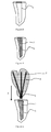
- the figure 3 represents a root canal 6. It is a cavity.
- the process can be performed on any laboratory model having a cavity.
- step 1) the root canal 6, or the cavity, is filled with a first composite resin 7 ( figure 4 ). Preferably, it is completely filled with resin.
- the reinforcing structure 1 is impregnated with a second composite resin 8 (step 2).
- the reinforcing structure 1 is impregnated to saturation, that is to say that at least the rods 2 of the reinforcing structure 1 are completely covered by the first composite resin 8 ( figure 5 ).
- the first composite resin 7 and the second composite resin 8 are identical, that is to say that they are of the same nature, it is the same resin. Even more preferentially, the first composite resin 7 and the second composite resin 8 are one and the same bonding resin. This allows a better mechanical support.
- the resins are polymerizable.
- the same composite glue is used for the preparation of the coronal portion, the corono-radicular portion and the apical portion of the corono-radicular dental reconstruction.
- the second composite resin 8 independently including each rod 2 may be different from the first composite resin 7.
- step 3 the reinforcing structure 1, impregnated with the second composite resin 8, is inserted into the dental canal 6 (arrow F of the figure 5 ).
- all the rods 2 of the reinforcing structure 1 are held by the connecting element 5.
- the connecting element 5 is positioned in the apical part of the structure, so as to be in contact with the bore operated with the preparation drill ( figure 6 ).
- the assembly element 5 advantageously has the same geometry as the apex of the reaming drill used during the preparation of the dental canal 6.
- the assembly element 5 thus fits perfectly in the dental canal 6
- a precise adaptation of the tenon makes it possible to improve both the retention and the bonding but also the flow of the functional constraints.
- the rods 2 of the reinforcing structure 1 are continuously dispersed in the entirety of the first composite resin 7 for reconstitution.
- the reinforcement structure 1 adapts to the geometry of the cavity by sliding the rods 2 relative to each other.
- step 4 the first composite resin 7 and the second composite resin 8 are polymerized. After polymerization, the stems 2 are fixed in the corono-radicular reconstitution 9.
- the polymerization makes it possible to constitute a corono-radicular dental reconstruction 9 ensuring its rigidity by its own shape and the architecture of its reinforcements.
- the coronal portion is advantageously formed of the same rods 2 as the root portion.
- the corono-radicular dental reconstruction 9, obtained according to the method, is carried out without proceeding to rectify the dental canal 6 in its corono-radicular part, up to 2/3 of the coronal portion.
- the canal can be instrumented with variable taper reamers to perform endodontic treatment.
- the conicity is defined by this instrumentalization.
- a second structure 10 may be deposited on the first reinforcing structure 1, the rods 11 of the second reinforcing structure 10 entangled in the rods 2 of the first reinforcing structure 1 by sliding.
- the second reinforcing structure 10 is inserted into the first structure 1 (arrow F 'of the figure 7 ).
- the second reinforcing structure 10 adapts to the first structure 1 by sliding against the root rods 2 to form a multidimensional fiber network.
- the second reinforcing structure 10 is also formed of a bundle of rods 11 of composite material: long fibers elongated in the major axis of each rod are covered with a fully polymerized polymer.
- the rods 11 are independent of each other.
- the rods 11 of the second reinforcing structure 10 are held by an assembly element 12.
- the rods 11 of the second reinforcing structure 10 may also be covered with a polymerizable composite resin before being capped into the first reinforcing structure 1.
- the resin composite is the same as that covering the rods 2 of the first structure 1.
- the rods 2 of the first reinforcing structure 1 have a sufficient amount of composite resin and there is no need to add resin on the rods 11 of the second reinforcing structure 10 (case of the schematic representation of the figure 7 ).
- a network of entangled rods 2, 11 is obtained ( figure 8 ).
- the mechanical stresses are better distributed and the structure is stronger.
- the corono-radicular dental reconstruction 9 obtained by the method comprises at least one reinforcing structure 1, the reinforcing structure 1 being embedded in at least one polymerized composite resin.
- the fiber-reinforced composite material structure for corono-radicular dental reconstruction comprises a bundle of rods that are independent of each other. A portion of the rods is secured by an assembly element.
- the reinforcing structure and the resin form a self-supporting structure ensuring the rigidity of the reconstitution.
- the dental reconstitution comprises two reinforcing structures 1, 10, arranged one above the other, the rods 2, 11 of the two structures being entangled.
- the additional reinforcing structure, the coronal reinforcement structure is complementary to the first root reinforcement structure 1.
- the dental reconstitution may also comprise reinforcement structures 1, 10 inserted side by side in the same dental canal 6 ( figure 9 ).
- the two reinforcing structures 1, 10 are inserted in the same dental canal to form the same reconstitution corono-radicular dental.
- the connecting elements 5, 12 of each reinforcing structure 1, 10 are arranged side by side in the channel and the rods 2, 11 of the two reinforcing structures intermingle.
- the number of rods and / or the diameter of the rods is adapted according to the shape and the size of the cavity intended to receive the reinforcement structure.
- the rods 2, 11 of each structure are independent of each other and flexibly adapt to the natural morphology of a dental canal without bore to a defined shape.
- the connecting element 5 is a heat-shrinkable sheath.
- heat-shrinkable is meant an element having the property of retracting under the action of heat.
- Sheath means a holster, a sleeve that can adapt to the shape, size of the bundle of rods.
- the reinforcement structures 1, 10, provided with heat-shrinkable sheath are inserted into the channel: the rods 2, 11 are located at the root portion of the channel and the connecting member 5, 12 is positioned above the coronal portion.
- the connecting element is distal to the apical portion of the dental canal.
- the assembly element 5 advantageously plays the role of a gripper.
- a second reinforcing structure 10 can be deposited next to the first reinforcing structure 1, in the dental canal 6 ( figure 11 ).
- the assembly element 5, 12 is eliminated at the end of the corono-root dental reconstruction process.
- this positioning of the reinforcement structures can also be achieved with a bundle of rods provided with an assembly element of another nature. It can be a simple sheath, a sleeve, or any element to hold the rods together, in the form of a beam.
- the assembly element can initiate any shape to the bundle of rods, flattened in the same plane, ovoid, circular, triangular. There is no limit to the possible forms.
- the number of reinforcement structures 1, 10 inserted in the dental canal depends on the size of said channel.
- the figure 10 represents, for example, a channel in which is inserted a single reinforcing structure.
- the figure 11 represents a channel in which two reinforcing structures are inserted side by side.
- the corono-radicular reconstitution can be performed, for example, on dental laboratory models.
- the reinforcement structure or structures extend throughout the volume of the root portion and the supra-gingival coronal portion of the corono-radicular dental reconstruction. They make it possible to reinforce in continuity the totality of the material of the reconstitution constituting the coronal part but also the root part.
Applications Claiming Priority (1)
| Application Number | Priority Date | Filing Date | Title |
|---|---|---|---|
| FR1400956A FR3020264B1 (fr) | 2014-04-23 | 2014-04-23 | Structure de renfort pour reconstitution dentaire corono-radiculaire, procede de realisation d'une reconstitution dentaire corono-radiculaire, reconstitution dentaire corono-radiculaire |
Publications (2)
| Publication Number | Publication Date |
|---|---|
| EP2937062A1 true EP2937062A1 (de) | 2015-10-28 |
| EP2937062B1 EP2937062B1 (de) | 2017-11-01 |
Family
ID=51014358
Family Applications (1)
| Application Number | Title | Priority Date | Filing Date |
|---|---|---|---|
| EP15164727.8A Active EP2937062B1 (de) | 2014-04-23 | 2015-04-22 | Verstärkungsstruktur für den zahnaufbau mit wurzelstift und stiftaufbau, verfahren zur umsetzung eines solchen zahnaufbaus mit wurzelstift und stiftaufbau, und zahnaufbau mit wurzelstift und stiftaufbau |
Country Status (4)
| Country | Link |
|---|---|
| US (1) | US9839493B2 (de) |
| EP (1) | EP2937062B1 (de) |
| CA (1) | CA2888842C (de) |
| FR (1) | FR3020264B1 (de) |
Cited By (1)
| Publication number | Priority date | Publication date | Assignee | Title |
|---|---|---|---|---|
| EP3470014A1 (de) * | 2017-10-12 | 2019-04-17 | Bruno Clunet-Coste | Zahntechnischer stumpfaufbau, herstellungsverfahren eines solchen stumpfaufbaus und ätzungsverfahren eines solchen zahntechnischen stumpfaufbaus |
Families Citing this family (1)
| Publication number | Priority date | Publication date | Assignee | Title |
|---|---|---|---|---|
| FR3058886B1 (fr) | 2016-11-22 | 2022-02-11 | Bernard Maneuf | Structure de renfort pour reconstitution dentaire corono-radiculaire, procede de realisation d’une reconstitution dentaire corono-radiculaire, reconstitution dentaire corono-radiculaire. |
Citations (12)
| Publication number | Priority date | Publication date | Assignee | Title |
|---|---|---|---|---|
| GB1255875A (en) | 1968-11-21 | 1971-12-01 | Louyot Comptoir Lyon Alemand | Improvements in and relating to dental pivots |
| CH562605A5 (en) | 1974-03-21 | 1975-06-13 | Spang Herbert | Steel anchor for artificial tooth crown - lower threaded spindle carries segmented flanges |
| FR2588181A1 (fr) | 1985-10-07 | 1987-04-10 | Jean Barbe | Nouvelles protheses endobuccales en matieres composites |
| DE3825601A1 (de) | 1988-07-28 | 1989-03-09 | Strobl Walter | Intrakanalaer zu verankernder zahnhartsubstanzaufbau |
| US4936776A (en) | 1988-07-05 | 1990-06-26 | Kwiatkowski Stephen J | Dental product and method utilizing translucent material |
| EP0432001A1 (de) | 1989-11-20 | 1991-06-12 | Marc Reynaud | Anker für die Dental-Prothetik aus vielfältigem Material und sein Herstellungsverfahren |
| FR2669211A2 (fr) * | 1989-03-02 | 1992-05-22 | Bernadat Georges | Prothese de reconstitution d'une dent devitalisee et appareil pour son implantation. |
| FR2730627A1 (fr) * | 1995-02-17 | 1996-08-23 | Marc Reynaud | Renfort dentaire autobloquant |
| FR2753365A1 (fr) | 1996-09-17 | 1998-03-20 | Billet Gilles | Insert endodontique d'obturation canalaire dentaire preimpregne a renforts de fibres |
| US5915970A (en) * | 1993-09-27 | 1999-06-29 | Tru-Flex Post Systems, Inc. | Flexible post in a dental post and core system |
| WO1999045859A1 (fr) * | 1998-03-10 | 1999-09-16 | Sun Medical Co., Ltd. | Pivot dentaire, renforcement de materiau de noyau pour la fabrication d'un pivot dentaire et kit permettant la fabrication d'un pivot dentaire |
| US20110294095A1 (en) * | 2009-02-18 | 2011-12-01 | Adm A.S. | Tooth stump structure, production method and design thereof |
Family Cites Families (2)
| Publication number | Priority date | Publication date | Assignee | Title |
|---|---|---|---|---|
| US6371763B1 (en) * | 1997-11-28 | 2002-04-16 | Robert J. Sicurelli, Jr. | Flexible post in a dental post and core system |
| FI980528A (fi) * | 1998-03-09 | 1999-09-10 | Bioxid Oy | Uusi prepreg |
-
2014
- 2014-04-23 FR FR1400956A patent/FR3020264B1/fr active Active
-
2015
- 2015-04-22 EP EP15164727.8A patent/EP2937062B1/de active Active
- 2015-04-22 CA CA2888842A patent/CA2888842C/en active Active
- 2015-04-23 US US14/694,117 patent/US9839493B2/en active Active
Patent Citations (12)
| Publication number | Priority date | Publication date | Assignee | Title |
|---|---|---|---|---|
| GB1255875A (en) | 1968-11-21 | 1971-12-01 | Louyot Comptoir Lyon Alemand | Improvements in and relating to dental pivots |
| CH562605A5 (en) | 1974-03-21 | 1975-06-13 | Spang Herbert | Steel anchor for artificial tooth crown - lower threaded spindle carries segmented flanges |
| FR2588181A1 (fr) | 1985-10-07 | 1987-04-10 | Jean Barbe | Nouvelles protheses endobuccales en matieres composites |
| US4936776A (en) | 1988-07-05 | 1990-06-26 | Kwiatkowski Stephen J | Dental product and method utilizing translucent material |
| DE3825601A1 (de) | 1988-07-28 | 1989-03-09 | Strobl Walter | Intrakanalaer zu verankernder zahnhartsubstanzaufbau |
| FR2669211A2 (fr) * | 1989-03-02 | 1992-05-22 | Bernadat Georges | Prothese de reconstitution d'une dent devitalisee et appareil pour son implantation. |
| EP0432001A1 (de) | 1989-11-20 | 1991-06-12 | Marc Reynaud | Anker für die Dental-Prothetik aus vielfältigem Material und sein Herstellungsverfahren |
| US5915970A (en) * | 1993-09-27 | 1999-06-29 | Tru-Flex Post Systems, Inc. | Flexible post in a dental post and core system |
| FR2730627A1 (fr) * | 1995-02-17 | 1996-08-23 | Marc Reynaud | Renfort dentaire autobloquant |
| FR2753365A1 (fr) | 1996-09-17 | 1998-03-20 | Billet Gilles | Insert endodontique d'obturation canalaire dentaire preimpregne a renforts de fibres |
| WO1999045859A1 (fr) * | 1998-03-10 | 1999-09-16 | Sun Medical Co., Ltd. | Pivot dentaire, renforcement de materiau de noyau pour la fabrication d'un pivot dentaire et kit permettant la fabrication d'un pivot dentaire |
| US20110294095A1 (en) * | 2009-02-18 | 2011-12-01 | Adm A.S. | Tooth stump structure, production method and design thereof |
Cited By (3)
| Publication number | Priority date | Publication date | Assignee | Title |
|---|---|---|---|---|
| EP3470014A1 (de) * | 2017-10-12 | 2019-04-17 | Bruno Clunet-Coste | Zahntechnischer stumpfaufbau, herstellungsverfahren eines solchen stumpfaufbaus und ätzungsverfahren eines solchen zahntechnischen stumpfaufbaus |
| FR3072274A1 (fr) * | 2017-10-12 | 2019-04-19 | Bruno Clunet Coste | Reconstitution dentaire corono-radiculaire, procede de realisation d’une telle reconstitution et procede de gravure d’une telle reconstitution dentaire |
| US11364096B2 (en) | 2017-10-12 | 2022-06-21 | Bruno Clunet-Coste | Crown and root dental restoration, method for performing one such restoration and method for etching one such dental restoration |
Also Published As
| Publication number | Publication date |
|---|---|
| FR3020264A1 (fr) | 2015-10-30 |
| CA2888842C (en) | 2022-08-30 |
| EP2937062B1 (de) | 2017-11-01 |
| US20150305829A1 (en) | 2015-10-29 |
| US9839493B2 (en) | 2017-12-12 |
| CA2888842A1 (en) | 2015-10-23 |
| FR3020264B1 (fr) | 2022-12-30 |
Similar Documents
| Publication | Publication Date | Title |
|---|---|---|
| EP2843193B1 (de) | Verbundstoff-laufradschaufel, die durch additive fertigung erzeugt wird und entsprechendes herstellungsverfahren | |
| FR3072274B1 (fr) | Reconstitution dentaire corono-radiculaire, procede de realisation d’une telle reconstitution et procede de gravure d’une telle reconstitution dentaire | |
| EP2843192B1 (de) | Verbundstoff-Laufradschaufel, die durch additives Fertigungsverfahren herstellt wird und entsprechendes Herstellungsverfahren | |
| EP2618772B1 (de) | Endodontisches instrument, dessen arbeitsabschnitt einen spalt aufweist, der einen durchgang für eine flüssigkeit bildet | |
| EP1511372B1 (de) | Mähfaden für vegetation-mähapparat | |
| WO1998011842A1 (fr) | Insert endodontique d'obturation canalaire dentaire preimpregne a renfort de fibres | |
| EP2315553A1 (de) | Vorrichtung zur injektion eines füllstoffes in der fluidphase in einen kanalraum | |
| WO2010149768A2 (fr) | Procede de fabrication de bielles composites et bielles obtenues selon le procede | |
| EP2937062B1 (de) | Verstärkungsstruktur für den zahnaufbau mit wurzelstift und stiftaufbau, verfahren zur umsetzung eines solchen zahnaufbaus mit wurzelstift und stiftaufbau, und zahnaufbau mit wurzelstift und stiftaufbau | |
| FR2643812A1 (fr) | Procede de renforcement d'une dent devitalisee et moyen pour sa mise en oeuvre | |
| FR2935162A1 (fr) | Element de fixation male composite-metal | |
| EP3544543B1 (de) | Verstärkungsstruktur für koronal-radikuläre zahnrestauration und anwendungsverfahren auf einem labormodell. | |
| CA2080532C (fr) | Rotor multipale, notamment pour helice arriere anticouple d'helicoptere et procede pour sa realisation | |
| WO1996015731A9 (fr) | Ensemble de reconstitution corono-radiculaire en materiau composite a gradient de module d'elasticite, et son procede de fabrication | |
| FR3044890A1 (fr) | Disque usinable par cfao pour la fabrication d'inlay core fibres | |
| EP1440668B1 (de) | Dentales Werkzeug zum entfernen eines Gegenstands aus einem Zahnwurzelkanal | |
| EP2083652B1 (de) | Applikator für ein kosmetisches produkt | |
| WO2010031957A1 (fr) | Brosse pour un applicateur de mascara comprenant des dents formant des rangs transversaux | |
| BE1005120A3 (fr) | Canne a peche armee de fibres de carbone. | |
| EP1121492A1 (de) | Ablenkvorrichtung für schrägseile | |
| FR3089450A1 (fr) | Procédé de fabrication d’un caisson central de voilure d’aéronef comportant au moins un raidisseur présentant au moins un trou traversant et caisson central de voilure d’aéronef obtenu à partir dudit procédé | |
| FR2861287A1 (fr) | Ancrage canalaire dentaire anatomique profile prefabrique | |
| EP0901550A1 (de) | Tragbahre nadelvibrator | |
| WO2022162095A1 (fr) | Préforme usinable pour reconstruction corono-radiculaire, élément usinable comportant une telle préforme, procédé de réalisation d'une reconstitution corono-radiculaire et procédé de fabrication d'une préforme | |
| FR3110946A1 (fr) | Dispositif de jonction de bande transporteuse à câbles muni d'éléments de blocage de câble. |
Legal Events
| Date | Code | Title | Description |
|---|---|---|---|
| PUAI | Public reference made under article 153(3) epc to a published international application that has entered the european phase |
Free format text: ORIGINAL CODE: 0009012 |
|
| AK | Designated contracting states |
Kind code of ref document: A1 Designated state(s): AL AT BE BG CH CY CZ DE DK EE ES FI FR GB GR HR HU IE IS IT LI LT LU LV MC MK MT NL NO PL PT RO RS SE SI SK SM TR |
|
| AX | Request for extension of the european patent |
Extension state: BA ME |
|
| 17P | Request for examination filed |
Effective date: 20160428 |
|
| RBV | Designated contracting states (corrected) |
Designated state(s): AL AT BE BG CH CY CZ DE DK EE ES FI FR GB GR HR HU IE IS IT LI LT LU LV MC MK MT NL NO PL PT RO RS SE SI SK SM TR |
|
| GRAP | Despatch of communication of intention to grant a patent |
Free format text: ORIGINAL CODE: EPIDOSNIGR1 |
|
| INTG | Intention to grant announced |
Effective date: 20170522 |
|
| RAP1 | Party data changed (applicant data changed or rights of an application transferred) |
Owner name: CLUNET-COSTE, BRUNO Owner name: COLLOMBIN, ANDRE Owner name: MANEUF, BERNARD |
|
| RIN1 | Information on inventor provided before grant (corrected) |
Inventor name: CLUNET-COSTE, BRUNO Inventor name: MANEUF, BERNARD Inventor name: COLLOMBIN, ANDRE |
|
| GRAS | Grant fee paid |
Free format text: ORIGINAL CODE: EPIDOSNIGR3 |
|
| GRAA | (expected) grant |
Free format text: ORIGINAL CODE: 0009210 |
|
| AK | Designated contracting states |
Kind code of ref document: B1 Designated state(s): AL AT BE BG CH CY CZ DE DK EE ES FI FR GB GR HR HU IE IS IT LI LT LU LV MC MK MT NL NO PL PT RO RS SE SI SK SM TR |
|
| REG | Reference to a national code |
Ref country code: GB Ref legal event code: FG4D Free format text: NOT ENGLISH |
|
| REG | Reference to a national code |
Ref country code: CH Ref legal event code: EP Ref country code: AT Ref legal event code: REF Ref document number: 941231 Country of ref document: AT Kind code of ref document: T Effective date: 20171115 |
|
| REG | Reference to a national code |
Ref country code: IE Ref legal event code: FG4D Free format text: LANGUAGE OF EP DOCUMENT: FRENCH |
|
| REG | Reference to a national code |
Ref country code: DE Ref legal event code: R096 Ref document number: 602015005664 Country of ref document: DE |
|
| REG | Reference to a national code |
Ref country code: NL Ref legal event code: MP Effective date: 20171101 |
|
| REG | Reference to a national code |
Ref country code: LT Ref legal event code: MG4D |
|
| REG | Reference to a national code |
Ref country code: AT Ref legal event code: MK05 Ref document number: 941231 Country of ref document: AT Kind code of ref document: T Effective date: 20171101 |
|
| REG | Reference to a national code |
Ref country code: FR Ref legal event code: PLFP Year of fee payment: 4 |
|
| PG25 | Lapsed in a contracting state [announced via postgrant information from national office to epo] |
Ref country code: NL Free format text: LAPSE BECAUSE OF FAILURE TO SUBMIT A TRANSLATION OF THE DESCRIPTION OR TO PAY THE FEE WITHIN THE PRESCRIBED TIME-LIMIT Effective date: 20171101 Ref country code: SE Free format text: LAPSE BECAUSE OF FAILURE TO SUBMIT A TRANSLATION OF THE DESCRIPTION OR TO PAY THE FEE WITHIN THE PRESCRIBED TIME-LIMIT Effective date: 20171101 Ref country code: LT Free format text: LAPSE BECAUSE OF FAILURE TO SUBMIT A TRANSLATION OF THE DESCRIPTION OR TO PAY THE FEE WITHIN THE PRESCRIBED TIME-LIMIT Effective date: 20171101 Ref country code: FI Free format text: LAPSE BECAUSE OF FAILURE TO SUBMIT A TRANSLATION OF THE DESCRIPTION OR TO PAY THE FEE WITHIN THE PRESCRIBED TIME-LIMIT Effective date: 20171101 Ref country code: ES Free format text: LAPSE BECAUSE OF FAILURE TO SUBMIT A TRANSLATION OF THE DESCRIPTION OR TO PAY THE FEE WITHIN THE PRESCRIBED TIME-LIMIT Effective date: 20171101 Ref country code: NO Free format text: LAPSE BECAUSE OF FAILURE TO SUBMIT A TRANSLATION OF THE DESCRIPTION OR TO PAY THE FEE WITHIN THE PRESCRIBED TIME-LIMIT Effective date: 20180201 |
|
| PG25 | Lapsed in a contracting state [announced via postgrant information from national office to epo] |
Ref country code: HR Free format text: LAPSE BECAUSE OF FAILURE TO SUBMIT A TRANSLATION OF THE DESCRIPTION OR TO PAY THE FEE WITHIN THE PRESCRIBED TIME-LIMIT Effective date: 20171101 Ref country code: RS Free format text: LAPSE BECAUSE OF FAILURE TO SUBMIT A TRANSLATION OF THE DESCRIPTION OR TO PAY THE FEE WITHIN THE PRESCRIBED TIME-LIMIT Effective date: 20171101 Ref country code: GR Free format text: LAPSE BECAUSE OF FAILURE TO SUBMIT A TRANSLATION OF THE DESCRIPTION OR TO PAY THE FEE WITHIN THE PRESCRIBED TIME-LIMIT Effective date: 20180202 Ref country code: BG Free format text: LAPSE BECAUSE OF FAILURE TO SUBMIT A TRANSLATION OF THE DESCRIPTION OR TO PAY THE FEE WITHIN THE PRESCRIBED TIME-LIMIT Effective date: 20180201 Ref country code: LV Free format text: LAPSE BECAUSE OF FAILURE TO SUBMIT A TRANSLATION OF THE DESCRIPTION OR TO PAY THE FEE WITHIN THE PRESCRIBED TIME-LIMIT Effective date: 20171101 Ref country code: AT Free format text: LAPSE BECAUSE OF FAILURE TO SUBMIT A TRANSLATION OF THE DESCRIPTION OR TO PAY THE FEE WITHIN THE PRESCRIBED TIME-LIMIT Effective date: 20171101 Ref country code: IS Free format text: LAPSE BECAUSE OF FAILURE TO SUBMIT A TRANSLATION OF THE DESCRIPTION OR TO PAY THE FEE WITHIN THE PRESCRIBED TIME-LIMIT Effective date: 20180301 |
|
| PG25 | Lapsed in a contracting state [announced via postgrant information from national office to epo] |
Ref country code: DK Free format text: LAPSE BECAUSE OF FAILURE TO SUBMIT A TRANSLATION OF THE DESCRIPTION OR TO PAY THE FEE WITHIN THE PRESCRIBED TIME-LIMIT Effective date: 20171101 Ref country code: CY Free format text: LAPSE BECAUSE OF FAILURE TO SUBMIT A TRANSLATION OF THE DESCRIPTION OR TO PAY THE FEE WITHIN THE PRESCRIBED TIME-LIMIT Effective date: 20171101 Ref country code: EE Free format text: LAPSE BECAUSE OF FAILURE TO SUBMIT A TRANSLATION OF THE DESCRIPTION OR TO PAY THE FEE WITHIN THE PRESCRIBED TIME-LIMIT Effective date: 20171101 Ref country code: SK Free format text: LAPSE BECAUSE OF FAILURE TO SUBMIT A TRANSLATION OF THE DESCRIPTION OR TO PAY THE FEE WITHIN THE PRESCRIBED TIME-LIMIT Effective date: 20171101 Ref country code: CZ Free format text: LAPSE BECAUSE OF FAILURE TO SUBMIT A TRANSLATION OF THE DESCRIPTION OR TO PAY THE FEE WITHIN THE PRESCRIBED TIME-LIMIT Effective date: 20171101 |
|
| REG | Reference to a national code |
Ref country code: DE Ref legal event code: R097 Ref document number: 602015005664 Country of ref document: DE |
|
| PG25 | Lapsed in a contracting state [announced via postgrant information from national office to epo] |
Ref country code: SM Free format text: LAPSE BECAUSE OF FAILURE TO SUBMIT A TRANSLATION OF THE DESCRIPTION OR TO PAY THE FEE WITHIN THE PRESCRIBED TIME-LIMIT Effective date: 20171101 Ref country code: IT Free format text: LAPSE BECAUSE OF FAILURE TO SUBMIT A TRANSLATION OF THE DESCRIPTION OR TO PAY THE FEE WITHIN THE PRESCRIBED TIME-LIMIT Effective date: 20171101 Ref country code: RO Free format text: LAPSE BECAUSE OF FAILURE TO SUBMIT A TRANSLATION OF THE DESCRIPTION OR TO PAY THE FEE WITHIN THE PRESCRIBED TIME-LIMIT Effective date: 20171101 Ref country code: PL Free format text: LAPSE BECAUSE OF FAILURE TO SUBMIT A TRANSLATION OF THE DESCRIPTION OR TO PAY THE FEE WITHIN THE PRESCRIBED TIME-LIMIT Effective date: 20171101 |
|
| PLBE | No opposition filed within time limit |
Free format text: ORIGINAL CODE: 0009261 |
|
| STAA | Information on the status of an ep patent application or granted ep patent |
Free format text: STATUS: NO OPPOSITION FILED WITHIN TIME LIMIT |
|
| PG25 | Lapsed in a contracting state [announced via postgrant information from national office to epo] |
Ref country code: MT Free format text: LAPSE BECAUSE OF FAILURE TO SUBMIT A TRANSLATION OF THE DESCRIPTION OR TO PAY THE FEE WITHIN THE PRESCRIBED TIME-LIMIT Effective date: 20171101 |
|
| 26N | No opposition filed |
Effective date: 20180802 |
|
| PG25 | Lapsed in a contracting state [announced via postgrant information from national office to epo] |
Ref country code: MC Free format text: LAPSE BECAUSE OF FAILURE TO SUBMIT A TRANSLATION OF THE DESCRIPTION OR TO PAY THE FEE WITHIN THE PRESCRIBED TIME-LIMIT Effective date: 20171101 Ref country code: SI Free format text: LAPSE BECAUSE OF FAILURE TO SUBMIT A TRANSLATION OF THE DESCRIPTION OR TO PAY THE FEE WITHIN THE PRESCRIBED TIME-LIMIT Effective date: 20171101 |
|
| REG | Reference to a national code |
Ref country code: IE Ref legal event code: MM4A |
|
| PG25 | Lapsed in a contracting state [announced via postgrant information from national office to epo] |
Ref country code: LU Free format text: LAPSE BECAUSE OF NON-PAYMENT OF DUE FEES Effective date: 20180422 |
|
| PG25 | Lapsed in a contracting state [announced via postgrant information from national office to epo] |
Ref country code: IE Free format text: LAPSE BECAUSE OF NON-PAYMENT OF DUE FEES Effective date: 20180422 |
|
| PG25 | Lapsed in a contracting state [announced via postgrant information from national office to epo] |
Ref country code: TR Free format text: LAPSE BECAUSE OF FAILURE TO SUBMIT A TRANSLATION OF THE DESCRIPTION OR TO PAY THE FEE WITHIN THE PRESCRIBED TIME-LIMIT Effective date: 20171101 |
|
| PG25 | Lapsed in a contracting state [announced via postgrant information from national office to epo] |
Ref country code: PT Free format text: LAPSE BECAUSE OF FAILURE TO SUBMIT A TRANSLATION OF THE DESCRIPTION OR TO PAY THE FEE WITHIN THE PRESCRIBED TIME-LIMIT Effective date: 20171101 |
|
| PG25 | Lapsed in a contracting state [announced via postgrant information from national office to epo] |
Ref country code: MK Free format text: LAPSE BECAUSE OF NON-PAYMENT OF DUE FEES Effective date: 20171101 Ref country code: HU Free format text: LAPSE BECAUSE OF FAILURE TO SUBMIT A TRANSLATION OF THE DESCRIPTION OR TO PAY THE FEE WITHIN THE PRESCRIBED TIME-LIMIT; INVALID AB INITIO Effective date: 20150422 |
|
| PG25 | Lapsed in a contracting state [announced via postgrant information from national office to epo] |
Ref country code: AL Free format text: LAPSE BECAUSE OF FAILURE TO SUBMIT A TRANSLATION OF THE DESCRIPTION OR TO PAY THE FEE WITHIN THE PRESCRIBED TIME-LIMIT Effective date: 20171101 |
|
| PGFP | Annual fee paid to national office [announced via postgrant information from national office to epo] |
Ref country code: FR Payment date: 20230426 Year of fee payment: 9 Ref country code: DE Payment date: 20230427 Year of fee payment: 9 Ref country code: CH Payment date: 20230502 Year of fee payment: 9 |
|
| PGFP | Annual fee paid to national office [announced via postgrant information from national office to epo] |
Ref country code: BE Payment date: 20230427 Year of fee payment: 9 |
|
| PGFP | Annual fee paid to national office [announced via postgrant information from national office to epo] |
Ref country code: GB Payment date: 20230426 Year of fee payment: 9 |