EP2936964A1 - Abscheideeinrichtung für einen Mähdrescher - Google Patents
Abscheideeinrichtung für einen Mähdrescher Download PDFInfo
- Publication number
- EP2936964A1 EP2936964A1 EP15153950.9A EP15153950A EP2936964A1 EP 2936964 A1 EP2936964 A1 EP 2936964A1 EP 15153950 A EP15153950 A EP 15153950A EP 2936964 A1 EP2936964 A1 EP 2936964A1
- Authority
- EP
- European Patent Office
- Prior art keywords
- separator
- housing
- gutstromeingriffselement
- gutstromeingriffselements
- gutstromeingriffsmittel
- Prior art date
- Legal status (The legal status is an assumption and is not a legal conclusion. Google has not performed a legal analysis and makes no representation as to the accuracy of the status listed.)
- Granted
Links
Images

Classifications
-
- A—HUMAN NECESSITIES
- A01—AGRICULTURE; FORESTRY; ANIMAL HUSBANDRY; HUNTING; TRAPPING; FISHING
- A01F—PROCESSING OF HARVESTED PRODUCE; HAY OR STRAW PRESSES; DEVICES FOR STORING AGRICULTURAL OR HORTICULTURAL PRODUCE
- A01F12/00—Parts or details of threshing apparatus
- A01F12/44—Grain cleaners; Grain separators
- A01F12/442—Rotary cleaners
-
- A—HUMAN NECESSITIES
- A01—AGRICULTURE; FORESTRY; ANIMAL HUSBANDRY; HUNTING; TRAPPING; FISHING
- A01D—HARVESTING; MOWING
- A01D41/00—Combines, i.e. harvesters or mowers combined with threshing devices
- A01D41/12—Details of combines
-
- A—HUMAN NECESSITIES
- A01—AGRICULTURE; FORESTRY; ANIMAL HUSBANDRY; HUNTING; TRAPPING; FISHING
- A01F—PROCESSING OF HARVESTED PRODUCE; HAY OR STRAW PRESSES; DEVICES FOR STORING AGRICULTURAL OR HORTICULTURAL PRODUCE
- A01F7/00—Threshing apparatus
- A01F7/02—Threshing apparatus with rotating tools
- A01F7/06—Threshing apparatus with rotating tools with axles in line with the feeding direction ; Axial threshing machines
- A01F7/067—Threshing apparatus with rotating tools with axles in line with the feeding direction ; Axial threshing machines with material-flow influencing means
Definitions
- the invention relates to a trained according to the preamble of claim 1 separating device for a combine harvester.
- This working according to the Axialpound tac deposition device has a housing with a Abscheidekorban ever and a lid assembly, which together form a hollow cylinder, and a Abscheiderotor, which is rotatably mounted in the hollow cylinder of the housing, so that between housing and Abscheiderotor a gap for conveying crop is defined circumferentially and along a longitudinal axis of the separator rotor.
- Gutstromeingriffsmittel are provided on a the separator motor facing the inner surface of the cover assembly, which are arranged circumferentially of the separator rotor ramp-like radially engage in a circumferential in the promotion of the crop in the intermediate crop flow to loosen this to hear the separation efficiency.
- the Gutstromeingriffsmittel have at least one ramped Gutstromeingriffselement, wherein a ramp height and thus an intensity of the engagement of the Gutstromeingriffselements is fixed in the circulating crop by a defined between the inner surface of the lid assembly and the Gutstromeingriffselement pitch angle or angle of attack.
- the Gutstromeingriffselement is releasably attached to the inner surface of the lid assembly.
- a good-current engagement element predetermining a fixed ramp height can be exchanged for a good-current engagement element predetermining another fixed ramp height.
- such an exchange requires a standstill of the separator, whereby the operating variability of the separator are limited.
- the invention has for its object to provide a trained according to the preamble of claim 1 separating device for a combine harvester, which has an increased operating variability.
- a separating device for a combine harvester operating according to the axial flow principle comprises a housing with a separating basket arrangement and a lid arrangement, which together form a hollow cylinder, and a separator rotor, which is received rotatably mounted in the hollow cylinder of the housing, so that between housing and separator rotor an intermediate space for conveying crop material is defined circumferentially and along a longitudinal axis of the separator rotor.
- Gutstromeingriffsmittel provided, which are arranged circumferentially of the separator rotor ramp-like radially engage in a circumferential in the circumferential promotion of the crop in the space Erntegutstrom.
- the separating device according to the invention is characterized in that the Gutstromeingriffssch are adjustable, so that a radial depth of engagement of the Gutstromeingriffssch is variable in the space defined between housing and Abscheiderotor gap, and that drive means are provided, which are connected to the Gutstromeingriffsschn for driving an adjustment of these and which can be controlled from outside the housing to the adjustment of the Gutstromeingriffsstoff.
- the Gutstromeingriffsmittel are adjustable so that their radial depth of engagement is variable in the space defined between the housing and Abscheiderotor, an intensity of engagement of the Gutstromeingriffselements can be changed in the rotating Erntegutstrom and thus to different operating conditions such as different crop to optimize the separation efficiency be adjusted.
- the Gutstromeingriffsmitteln for driving an adjustment of these connected drive means are controlled from outside the housing for adjusting the Gutstromeingriffsstoff, the adjustment of the radial depth of engagement can be carried out comfortably during operation of the separator, whereby the operating variability of the separator is increased.
- the Abscheidekorban ever one or more juxtaposed along the longitudinal axis of the Abscheiderotors sieve-like Abscheidekörbe comprise, wherein in each Abscheidekorb a plurality of passage openings are provided through which a to be separated Erntegutanteil such as grain from a Erntegutstrom in the between Housing and separator rotor defined gap circulates, can be deposited.
- the lid assembly may comprise one or more lid members longitudinally aligned along the longitudinal axis of the separator motor.
- the Gutstromeingriffsmittel at least one Gutstromeingriffselement with a width which is bounded by two along the longitudinal axis of the Abscheiderotors longitudinal edges of the Gutstromeingriffselements, wherein the at least one Gutstromeingriffselement along the longitudinal axis of the Abscheiderotors has a length which is at least a part of a axial extent of the inner surface of the lid assembly corresponds.
- the at least one Gutstromeingriffselement depending on the desired configuration along the longitudinal axis of the Abscheiderotors over the entire axial extent of the inner surface of the lid assembly or even extend over only a portion of the axial extent of the inner surface of the lid assembly.
- a plurality of Gutstromeingriffs may as the at least one Gutstromeingriffselement formed along the longitudinal axis of the Abscheiderotors their respective length without or with space in succession and each extending over a portion of the axial extent of the inner surface of the lid assembly.
- the Gutstromeingriffssch extend in their length over the entire length of the Abscheidekorban eleven.
- the at least one Gutstromeingriffselement the Gutstromeingriffssch may extend in its length over the entire length of the at least one separation basket of Abscheidekorbanix ever or more juxtaposed Gutstromeingriffsetti be provided that extend with their total length over the entire length of the at least one separation basket of Abscheidekorban eleven. It is also possible to provide a plurality of collection baskets arranged one next to the other, each Gutstromeingriffselement a plurality of juxtaposed Gutstromeingriffs instituten over the entire length of a positionally corresponding thereto each separating basket extends. Other configurations are of course also conceivable within the scope of the invention.
- one of the two longitudinal edges of the at least one Gutstromeingriffselements is pivotally mounted on a along the longitudinal axis of the Abscheiderotors pivot axis, so that for adjusting the Gutstromeingriffsmittel a between the inner surface of the lid assembly and the at least one Gutstromeingriffselement defined angle of attack by Swivel axis pivoting of the Gutstromeingriffselements is changeable.
- the adjustability of the at least one Gutstromeingriffselements could also be e.g. be realized by Linearverfahr Anlagen the at least one Gutstromeingriffselements.
- a passage slot extending longitudinally along the longitudinal axis of the separator rotor is formed in the lid assembly and the at least one crop flow engaging element is inserted longitudinally into the passage slot so that the one longitudinal edge of the crop flow engaging element is supported outwardly of the housing and the other longitudinal edge of the Gutstromeingriffselements is disposed within the housing, wherein the pivot axis is arranged outside of the housing.
- the pivot axis or axis of rotation of the at least one Gutstromeingriffselements is disposed outside of the housing, the pivot axis is not in operation of the separator in the circulating Erntegutstrom and therefore does not affect this.
- the passage slot circumferentially of the separator rotor has a width such that the at least one Gutstromeingriffselement can lean against the inner surface of the lid assembly with minimal incidence.
- the at least one Gutstromeingriffselement is formed so that it closes the passage slot in the region of the length of the at least one Gutstromeingriffselements at a minimum angle of incidence.
- the at least one crop stream engaging element may for this purpose be e.g. be formed closed in area cooperating with the passage slot and abut with minimal incidence similar to a valve flap along the passage slot on an outer surface of the lid assembly and on the inner surface of the lid assembly and thus close the passage slot.
- the deposition device further comprises a cover assembly having along the longitudinal axis of the separator rotor a length at least equal to the length of the passageway slot and circumferentially of the separator rotor having a width greater than the width of the passageway slot Cover assembly is disposed radially outwardly of the pivot axis along the length of the passage slot so that it covers the passage slot over its width spans.
- the cover assembly can also be counteracted in the deviating from the minimum engagement position positions of at least one Gutstromeingriffselements, such as in a maximum angle of attack having maximum engagement position, the fact that by the Through slit through crop emerges from the hollow cylindrical housing of the separator.
- the cover arrangement may comprise a single cover element which has at least the length of the passage slot, or also a plurality of cover elements arranged alongside one another along the longitudinal axis of the separator motor or the length of the passage slot, which together have at least the length of the passage slot.
- the cover assembly has at least one passage opening in the region of the pivot axis, wherein the drive means are arranged outside the housing and the at least one Gutstromeingriffselement is drivingly connected through the at least one through hole with the drive means.
- the at least one passage opening is provided in the region of the pivot between the cover assembly and cover pivot axis, the passage opening is concealed by the side of the passage slot forth from the pivot axis, so that counteracted the fact that emerges through the through-hole crop.
- the drive means are arranged outside of the housing, the drive means are not exposed to contamination by the Erntegutstrom and also favors their housing external drivability.
- the at least one Gutstromeingriffselement starting from its mounted on the pivot axis has a longitudinal edge over a predetermined width portion of its surface closed and close to the areal closed width section a plurality of comb-like juxtaposed engagement fingers whose free ends together define the other longitudinal edge of the Gutstromeingriffselements.
- this comb-like or rake-like configuration of the at least one Gutstromeingriffselements can in operation of the deposition device, for example. Straw of a circulating in the space Erntegutstroms be deflected and loosened from the inner surface of the lid assembly and can simultaneously grain contained in Erntegutstrom pass between the engagement fingers and along the inner surface of the lid assembly are transported to the Abscheidekorban ever and there for deposition exit from the housing.
- the engaging fingers may extend without inclination in the direction of the longitudinal axis of the separating rotor so that they do not affect the crop flow with respect to its transport in the axial direction, or the engaging fingers may extend with a predetermined inclination in the direction of the longitudinal axis of the separating rotor, so that they specifically influence the crop flow with respect to its transport in the axial direction.
- a plurality of coaxially to the longitudinal axis of the separator rotor spirally arranged side by side guide elements or guide rails may be provided which extend circumferentially sections in the radial direction of the cover assembly.
- the guide elements have by the helical extent a directional component in the axial direction of the separator rotor and thus support an axial promotion of Erntegutstroms of an input of the separator along the longitudinal axis of the separator to an output of the separator.
- the engagement fingers of the Gutstromeingriffselements can thereby extend with such an inclination in the direction of the longitudinal axis of the Abscheiderotors that their extension direction corresponds to that of the guide elements.
- the Gutstromeingriffsmittel more than the at least one Gutstromeingriffselement formed Gutstromeingriffs comprise along along the longitudinal axis of the separator rotor of their respective length are arranged without or with longitudinal spacing from each other in succession and which are independently adjustable so that their respective radial depth of engagement in the intermediate space is variable.
- the drive means for each of the Gutstromeingriffs comprise on its own drive unit, which is connected to the respective Gutstromeingriffselement for driving an adjustment and which can be controlled from outside the housing to the adjustment of the respective Gutstromeingriffselements.
- the separation device according to the invention can be even better adapted to the particular operating conditions for optimizing the separation efficiency.
- the drive means for adjusting the at least one Gutstromeingriffselements on a pneumatic cylinder.
- each drive unit of the drive means has a pneumatic cylinder for adjusting the respective connected Gutstromeingriffselements on.
- the pneumatic cylinder can also provide an overload protection function for the respective Gutstromeingriffselement simultaneously with its Verstellantriebsfunktion.
- the drive means for adjusting the at least one Gutstromeingriffselements on a hydraulic cylinder Preferably, each has Drive unit of the drive means on a hydraulic cylinder for adjusting the respective connected Gutstromeingriffselements on.
- a pressure limiting valve assigned to the hydraulic circuit of the at least one hydraulic cylinder can be used so that, starting from a specific force action, a deflection of the respectively displaced good-current engaging element, which is preferably in the direction of the minimum engagement position, is permitted in order to provide an overload protection function.
- FIGS. 1 to 4 a formed according to an embodiment of the invention according to the Axialpound tac working separator 10 of a combine harvester (not fully shown and not separately designated).
- Fig.1 shows a partial perspective view of the separator 10
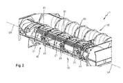
- Fig. 2 shows a partial perspective view of a separating unit 1 of the combine harvester provided with two such separating devices 10, 10 '.
- Fig. 1 how out Fig. 1 can be seen, the separator 10, a housing 11 with a Abscheidekorban let 13 and a cover assembly 15, which together form a hollow cylinder, and a Abscheiderotor 17 which is rotatably mounted in the hollow cylinder of the housing 11 is received, so that between the housing 11 and the separator 17th a gap Z1 to the circumference and along a longitudinal axis LA of the separator motor 17 conveying crop (not shown) is defined as cereals.
- the longitudinal axis LA forms at the same time as a central longitudinal axis an axis of rotation of the separator 17.
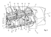
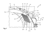
- FIGS. 2 to 4 It should be noted here that in these figures, the separator basket assembly 13 and the separator motor 17 are omitted. Moreover, in Fig. 2 and Fig. 3 a wall of the lid assembly 15 each shown transparent.
- the separating rotor 17 For conveying the crop, the separating rotor 17 has on its peripheral surface these spirally spanning carrier elements 18 which convey the crop in an axial conveying direction F1 and in a circumferential conveying direction F2 of the separating device 10.
- the separating basket arrangement 13 comprises at least one sieve-like separating basket 14, which forms a separating region of the separating device 10.
- a plurality of separation baskets 14 are arranged parallel to the longitudinal axis LA of the separation motor 17 in the axial direction one behind the other.
- the separator basket assembly 13 has a plurality of through holes (not separately indicated) through which ingredients (such as grains) may be separated from a crop stream fed to the separator 10.
- the lid assembly 15 comprises at least one lid member 16, wherein the lid assembly 15 and the Abscheidekorban ever 13 connected to each other the Abscheiderotor 17 seen in the circumferential direction approximately half surrounded and thus define the hollow cylinder of the housing 11.
- a plurality of cover elements 16 are arranged parallel to the longitudinal axis LA of the separator 17 in the axial direction one behind the other.
- the cover assembly 15 has on a the separator motor 17 facing inner surface 15.1 of these a plurality of coaxially to the longitudinal axis LA of the separator motor 17 side by side arranged vanes 15.2, the spirally arranged side by side circumferentially sections extend in the radial direction of the lid assembly 15.
- the guide elements 15.2 have by the helical extent a directional component in the axial conveying direction F1 of the separator 17 and thus support an axial promotion of crop flow of a Entrance of the separator 10 along the longitudinal axis LA of the separator 17 to an output of the separator 10th
- Gutstromeingriffsmittel 20 are also provided on the inner surface 15.1 of the lid assembly 15 facing the separator motor 17, which are arranged circumferentially of the separator motor 17, i. in the circumferential conveying direction F2, to intervene in a ramp-like manner radially into a crop stream circulating in the circumferential conveying direction F2 in the circumferential conveying of the crop in the intermediate space Z1.
- the Gutstromeingriffsmittel 20 have a plurality of comb-like Gutstromeingriffs instituten 21 (see Fig. 2 ) which are arranged one behind the other along the longitudinal axis LA of the separating motor 17 in their respective length and which are adjustable independently of one another so that their respective radial depth of engagement in the intermediate space Z1 is variable,
- Drive means 40 which are connected to the Gutstromeingriffsschn 20 for driving an adjustment of these and which can be controlled from outside the housing 11 for adjusting the Gutstromeingriffsstoff 20 are also provided on the separation device 10. More specifically, the drive means 40 for each of the Gutstromeingriffsimplantation 21 has its own drive unit 41 which is connected to the respective Gutstromeingriffselement 21 for driving an adjustment thereof and which can be controlled from outside the housing 11 for adjusting the respective Gutstromeingriffselements 21.
- each of the Gutstromeingriffs comprise 21 has a width which is bounded by two along the longitudinal axis LA of the Abscheiderotors 17 extending longitudinal edges 22, 23 of the Gutstromeingriffselements 21.
- each of the Gutstromeingriffs comprise 21 along the longitudinal axis LA of the separator motor 17 has a length which corresponds at least to a part of an axial extent of the inner surface 15.1 of the lid assembly 15.
- each Gutstromeingriffselement 21 extends over the entire length of a positionally corresponding thereto each separating basket 14 of the separating basket assembly 13th
- the lid assembly 15 is formed a longitudinally along the longitudinal axis LA of the separator motor 17 extending through slot 15.3.
- Each of the Gutstromeingriffsetti 21 is inserted alongside in the passage slot 15.3, so that the mounted on the pivot axis S1 one longitudinal edge 22 of the Gutstromeingriffselements 21 protrudes outwardly from the housing 11 and the other longitudinal edge 23 of the Gutstromeingriffselements 21 is disposed within the housing 11 in the intermediate space Z1 ,
- the pivot axis S1 is located outside the housing 11.
- Each Gutstromeingriffselement 21 is connected at its one longitudinal edge 22 with a longitudinally along the longitudinal axis LA of the Abscheiderotors 17 extending sleeve 24 which rotatably on a longitudinally along the longitudinal axis LA of the Abscheiderotors 17 extending, mounted on the housing 11 and all Gutstromeingriffs instituten 21 common axle 25 is pushed, so that the pivotability of the Gutstromeingriffselements 21 is ensured about the pivot axis S1.
- the separation device 10 also has a cover assembly 60 (only in FIG Fig. 2 and Fig. 3 shown), which along the longitudinal axis LA of the separator 17 has a length which corresponds at least to the length of the passage slot 15.3.
- the cover assembly 60 has circumferentially of the separator motor 17 has a width which is greater than the width of the passage slot 15.3.
- the cover assembly 60 is disposed radially outward of the pivot axis S1 along the length of the passageway slot 15.3 so as to cover the passageway slot 15.3 across its width.
- the cover arrangement 60 preferably comprises a plurality of cover elements 61 which are lined up along the longitudinal axis LA of the separator motor 17 or the length of the passage slot 15.3 and together have at least the length of the passage slot 15.3.
- a slot-shaped passage opening 62 is provided in the region of the pivot axis S1 for each Gutstromeingriffselement 21 through which an adjusting lever 51 of a connecting linkage 50 of the respective Gutstromeingriffselement 21 associated with the adjustment drive unit 41 with the one longitudinal edge 22 provided Sleeve 24 of the respective Gutstromeingriffselements 21 is connected.
- Each of the drive units 41 of the drive means 40 is arranged outside the housing 11 and has a pneumatic cylinder 42, the piston rod 43 via a pivotable about a pivot axis S2 rocker arm 52 and a ball head rod 53 of the connecting rod 50 with one of the sleeve 24th remote longitudinal end of the adjusting lever 51 of the connecting rod 50 is connected.
- each ball heads (not separately designated) of the ball head rod 53 of the connecting rod 50 adjustable by thread adjustment, so that a length of the ball head rod 53 is adjustable ,
- each Gutstromeingriffselement 21 is formed starting from its mounted on the pivot axis S1 a longitudinal edge 22 over a predetermined width section 21.1 whose area closed and close to the areal closed width section 21.1 a plurality of comb-like juxtaposed engagement fingers 21.2 whose free ends together the define another longitudinal edge 23 of the Gutstromeingriffselements 21.
- the engaging fingers 21.2 may extend without inclination in the direction of the longitudinal axis LA of the separator motor 17 so that they do not affect the Erntegutstrom with respect to its transport in the axial direction, or the engagement fingers 21.2 with a predetermined inclination in the direction of the longitudinal axis LA Separating rotor 17 extend so that they specifically affect the Erntegutstrom with respect to its transport in the axial direction.
- the engagement fingers 21.2 of the Gutstromeingriffsetti 21 may extend with such an inclination in the direction of the longitudinal axis LA of the Abscheiderotors 17 that their extension direction corresponds to that of the guide elements 15.2, which have a directional component in the axial direction of the Abscheiderotors 17 by their spiral extension.
- the passage slot 15.3 of the lid assembly 15 circumferentially of the separator motor 17 has such a width and the Gutstromeingriffs institute 21 are shaped so that the Gutstromeingriffs institute 21 can lean against the inner surface 15.1 of the lid assembly 15 at a minimum angle of attack W1.
- the good-current engaging elements 21, which may also be an inoperative position, a stable and defined end position for each Gutstromeingriffselement 21 are provided.
- each Gutstromeingriffselements 21 is formed wider than the passage slot 15.3, the Gutstromeingriffs institute 21 can close the passage slot 15.3 in the region of their respective longitudinal extent at a minimum angle of attack W1, as in Fig. 4 indicated.
- each pneumatic cylinder 42 via housing external extending compressed air lines 44, 45 fluidly connected to a control valve assembly (not shown), which in turn with a Compressed air source (not shown) of the combine is fluidly connected.
- the control valve arrangement is also signal-connected to a control device (not shown) of the combine for controlling it.
- the drive units 41 may include hydraulic cylinders instead of pneumatic cylinders that are fluidly connected by respective hydraulic lines to corresponding ones of a control valve assembly.
- electric drives such as linear motors can be used as drive units 41.
Landscapes
- Life Sciences & Earth Sciences (AREA)
- Environmental Sciences (AREA)
- Centrifugal Separators (AREA)
- Apparatuses For Bulk Treatment Of Fruits And Vegetables And Apparatuses For Preparing Feeds (AREA)
Abstract
Description
- Die Erfindung betrifft eine gemäß dem Oberbegriff des Anspruchs 1 ausgebildete Abscheideeinrichtung für einen Mähdrescher.
- Eine Abscheideeinrichtung der eingangsgenannten Art ist beispielsweise aus
EP 2 428 109 B1 bekannt. Diese nach dem Axialflussprinzip arbeitende Abscheideeinrichtung weist ein Gehäuse mit einer Abscheidekorbanordnung und einer Deckelanordnung, die gemeinsam einen Hohlzylinder bilden, sowie einen Abscheiderotor auf, der drehbar gelagert in dem Hohlzylinder des Gehäuses aufgenommen ist, so dass zwischen Gehäuse und Abscheiderotor ein Zwischenraum zum Fördern von Erntegut umfänglich und entlang einer Längsachse des Abscheiderotors definiert ist. An einer dem Abscheiderotor zugewandten Innenfläche der Deckelanordnung sind Gutstromeingriffsmittel vorgesehen, die eingerichtet sind, umfänglich des Abscheiderotors rampenartig radial in einen bei der umfänglichen Förderung des Ernteguts im Zwischenraum umlaufenden Erntegutstrom einzugreifen, um diesen zur Erhörung der Abscheideleistung aufzulockern. - Die Gutstromeingriffsmittel weisen mindestens ein rampenförmiges Gutstromeingriffselement auf, wobei eine Rampenhöhe und damit eine Intensität des Eingriffs des Gutstromeingriffselements in den umlaufenden Erntegutstrom durch einen zwischen der Innenfläche der Deckelanordnung und dem Gutstromeingriffselement definierten Steigungswinkel beziehungsweise Anstellwinkel fest vorgegeben ist.
- Durch das rampenförmige Gutstromeingriffselement an der Innenfläche der Deckelanordnung wird der an der Innenfläche der Deckelanordnung umlaufende und sich dabei zu einer Erntegutmatte verdichtende Erntegutstrom wieder aufgelockert, indem dieser durch das Gutstromeingriffselement von der Innenfläche der Deckelanordnung abgehoben wird und anschließend auf diese zurückfällt.
- Um die Eingriffsstärke des Gutstromeingriffselements in den umlaufenden Erntegutstrom an unterschiedliche Betriebsbedingungen wie zum Beispiel unterschiedliches Erntegut anpassen zu können, ist das Gutstromeingriffselement lösbar an der Innenfläche der Deckelanordnung befestigt. Somit kann bei Bedarf ein eine feste Rampenhöhe vorgebendes Gutstromeingriffselement gegen ein eine andere feste Rampenhöhe vorgebendes Gutstromeingriffselement ausgetauscht werden. Ein solcher Austausch bedarf allerdings eines Stillstands der Abscheideeinrichtung, wodurch der Betriebsvariabilität der Abscheideeinrichtung Grenzen gesetzt sind.
- Der Erfindung liegt die Aufgabe zugrunde, eine gemäß dem Oberbegriff des Anspruchs 1 ausgebildete Abscheideeinrichtung für einen Mähdrescher bereitzustellen, welche eine erhöhte Betriebsvariabilität hat.
- Dies wird mit einer Abscheideeinrichtung gemäß Anspruch 1 erreicht. Weiterbildungen der Erfindung sind in den abhängigen Ansprüchen definiert.
- Gemäß der Erfindung weist eine nach dem Axialflussprinzip arbeitende Abscheideeinrichtung für einen Mähdrescher ein Gehäuse mit einer Abscheidekorbanordnung und einer Deckelanordnung, die gemeinsam einen Hohlzylinder bilden, und einen Abscheiderotor auf, der drehbar gelagert in dem Hohlzylinder des Gehäuses aufgenommen ist, so dass zwischen Gehäuse und Abscheiderotor ein Zwischenraum zum Fördern von Erntegut umfänglich und entlang einer Längsachse des Abscheiderotors definiert ist. An einer dem Abscheiderotor zugewandten Innenfläche der Deckelanordnung sind Gutstromeingriffsmittel vorgesehen, die eingerichtet sind, umfänglich des Abscheiderotors rampenartig radial in einen bei der umfänglichen Förderung des Ernteguts im Zwischenraum umlaufenden Erntegutstrom einzugreifen.
- Die erfindungsgemäße Abscheideeinrichtung zeichnet sich dadurch aus, dass die Gutstromeingriffsmittel verstellbar sind, so dass eine radiale Eingriffstiefe der Gutstromeingriffsmittel in den zwischen Gehäuse und Abscheiderotor definierten Zwischenraum veränderbar ist, und dass Antriebsmittel vorgesehen sind, die mit den Gutstromeingriffsmitteln zum Antreiben einer Verstellung dieser verbunden sind und die von außerhalb des Gehäuses aus zum Verstellantrieb der Gutstromeingriffsmittel ansteuerbar sind.
- Dadurch, dass die Gutstromeingriffsmittel verstellbar sind, so dass deren radiale Eingriffstiefe in den zwischen Gehäuse und Abscheiderotor definierten Zwischenraum veränderbar ist, kann eine Intensität des Eingriffs des Gutstromeingriffselements in den umlaufenden Erntegutstrom verändert und damit an unterschiedliche Betriebsbedingungen wie zum Beispiel unterschiedliches Erntegut zur Optimierung der Abscheideleistung angepasst werden. Dadurch, dass die mit den Gutstromeingriffsmitteln zum Antreiben einer Verstellung dieser verbundenen Antriebsmittel von außerhalb des Gehäuses aus zum Verstellantrieb der Gutstromeingriffsmittel ansteuerbar sind, kann die Verstellung von deren radialer Eingriffstiefe komfortabel während des Betriebs der Abscheideeinrichtung durchgeführt werden, wodurch die Betriebsvariabilität der Abscheideeinrichtung erhöht ist.
- Gemäß der Erfindung kann die Abscheidekorbanordnung einen oder mehrere längs entlang der Längsachse des Abscheiderotors aneinandergereihte siebartige Abscheidekörbe umfassen, wobei in jedem Abscheidekorb eine Vielzahl von Durchtrittsöffnungen vorgesehen sind, durch die hindurch ein abzuscheidender Erntegutanteil wie z.B. Korn aus einem Erntegutstrom, der in dem zwischen Gehäuse und Abscheiderotor definierten Zwischenraum umläuft, abgeschieden werden kann.
- Gemäß der Erfindung kann die Deckelanordnung ein oder mehrere längs entlang der Längsachse des Abscheiderotors aneinandergereihte Deckelelemente umfassen.
- Gemäß einer Ausführungsform der Erfindung weisen die Gutstromeingriffsmittel mindestens ein Gutstromeingriffselement mit einer Breite auf, welche von zwei entlang der Längsachse des Abscheiderotors verlaufenden Längsrändern des Gutstromeingriffselements begrenzt ist, wobei das mindestens eine Gutstromeingriffselement entlang der Längsachse des Abscheiderotors eine Länge aufweist, die zumindest einem Teil einer axialen Erstreckung der Innenfläche der Deckelanordnung entspricht.
- Mit anderen Worten kann sich das mindestens eine Gutstromeingriffselement je nach gewünschter Konfiguration entlang der Längsachse des Abscheiderotors über die gesamte axiale Erstreckung der Innenfläche der Deckelanordnung oder auch nur über einen Teil der axialen Erstreckung der Innenfläche der Deckelanordnung erstrecken. Gemäß der Erfindung ist es auch möglich, dass mehrere so wie das mindestens eine Gutstromeingriffselement ausgebildete Gutstromeingriffselemente entlang der Längsachse des Abscheiderotors ihrer jeweiligen Länge nach ohne oder mit Zwischenraum hintereinander angeordnet sind und sich dabei jeweils über einen Teil der axialen Erstreckung der Innenfläche der Deckelanordnung erstrecken.
- Auf diese Weise lässt sich die Intensität des radialen Eingriffs der Gutstromeingriffsmittel in den zwischen Gehäuse und Abscheiderotor definierten Zwischenraum zusätzlich über die axiale Erstreckung der Innenfläche der Deckelanordnung hinweg konfigurieren und damit an angenommene Betriebsbedingungen zur Optimierung der Abscheideleistung anpassen.
- Bevorzugt erstrecken sich die Gutstromeingriffsmittel in ihrer Länge über die gesamte Länge der Abscheidekorbanordnung. Gemäß der Erfindung kann sich das mindestens eine Gutstromeingriffselement der Gutstromeingriffsmittel in seiner Länge über die gesamte Länge des mindestens einen Abscheidekorbes der Abscheidekorbanordnung erstrecken oder können mehrere aneinandergereihte Gutstromeingriffselemente vorgesehen sein, die sich mit ihrer Gesamtlänge über die gesamte Länge des mindestens einen Abscheidekorbes der Abscheidekorbanordnung erstrecken. Auch können mehrere aneinandergereihte Abscheidekörbe vorgesehen sein, wobei sich jedes Gutstromeingriffselement einer Mehrzahl von aneinandergereihten Gutstromeingriffselementen über die gesamte Länge eines positionsmäßig jeweils dazu korrespondierenden Abscheidekorbes erstreckt. Andere Konfigurationen sind im Rahmen der Erfindung natürlich auch denkbar.
- Gemäß einer weiteren Ausführungsform der Erfindung ist einer der beiden Längsränder des mindestens einen Gutstromeingriffselements an einer sich entlang der Längsachse des Abscheiderotors erstreckenden Schwenkachse schwenkbar gelagert, so dass zum Verstellen der Gutstromeingriffsmittel ein zwischen der Innenfläche der Deckelanordnung und dem mindestens einen Gutstromeingriffselement definierter Anstellwinkel durch um die Schwenkachse Verschwenken des Gutstromeingriffselements veränderbar ist.
- Die Realisierung der Verstellbarkeit des mindestens einen Gutstromeingriffselements mittels schwenkbeweglicher Ausgestaltung dessen stellt eine einfache und damit kostengünstige Lösung bereit. Zudem kann eine schwenkbewegliche Ausführung des Gutstromeingriffselements die für den Feldeinsatz erforderliche Robustheit gewährleisten.
- Alternativ zur schwenkbeweglichen Ausgestaltung könnte die Verstellbarkeit des mindestens einen Gutstromeingriffselements auch z.B. mittels Linearverfahrbarkeit des mindestens einen Gutstromeingriffselements realisiert sein.
- Gemäß noch einer Ausführungsform der Erfindung ist in der Deckelanordnung ein sich längs entlang der Längsachse des Abscheiderotors erstreckender Durchgangsschlitz ausgebildet und ist das mindestens eine Gutstromeingriffselement längsseits in den Durchgangsschlitz eingesetzt, so dass der an der Schwenkachse gelagerte eine Längsrand des Gutstromeingriffselements aus dem Gehäuse nach außen vorsteht und der andere Längsrand des Gutstromeingriffselements innerhalb des Gehäuses angeordnet ist, wobei die Schwenkachse außerhalb des Gehäuses angeordnet ist.
- Dadurch, dass gemäß dieser Ausgestaltung der Erfindung die Schwenkachse bzw. Drehachse des mindestens einen Gutstromeingriffselements außerhalb des Gehäuses angeordnet ist, liegt die Schwenkachse im Betrieb der Abscheideeinrichtung nicht im umlaufenden Erntegutstrom und beeinträchtigt diesen daher nicht.
- Gemäß noch einer weiteren Ausführungsform der Erfindung weist der Durchgangsschlitz umfänglich des Abscheiderotors eine solche Breite auf, dass sich das mindestens eine Gutstromeingriffselement bei minimalem Anstellwinkel an die Innenfläche der Deckelanordnung anlehnen kann.
- Auf diese Weise kann in einer Minimaleingriffstellung des mindestens einen Gutstromeingriffselements, welche auch eine Außerbetriebsstellung sein kann, eine stabile und definierte Endlage für das mindestens eine Gutstromeingriffselement bereitgestellt werden.
- Gemäß einer Ausführungsform der Erfindung ist das mindestens eine Gutstromeingriffselement so ausgebildet, dass es bei minimalem Anstellwinkel dessen den Durchgangsschlitz im Bereich der Länge des mindestens einen Gutstromeingriffselements verschließt.
- Das mindestens eine Gutstromeingriffselement kann zu diesem Zweck z.B. im mit dem Durchgangsschlitz zusammenwirkenden Bereich flächenmäßig geschlossen ausgebildet sein und bei minimalem Anstellwinkel ähnlich einer Ventilklappe längs des Durchgangsschlitzes an einer Außenfläche der Deckelanordnung und an der Innenfläche der Deckelanordnung anliegen und so den Durchgangsschlitz verschließen.
- Damit kann in der Minimaleingriffstellung bzw. Außerbetriebsstellung des mindestens einen Gutstromeingriffselements sicher verhindert werden, dass Erntegut durch den Durchgangsschlitz hindurch aus dem hohlzylindrischen Gehäuse der Abscheideeinrichtung austreten kann.
- Gemäß noch einer Ausführungsform der Erfindung weist die Abscheideeinrichtung ferner eine Abdeckungsanordnung auf, die entlang der Längsachse des Abscheiderotors eine Länge, die mindestens der Länge des Durchgangsschlitzes entspricht, und umfänglich des Abscheiderotors eine Breite aufweist, die größer als die Breite des Durchgangsschlitzes ist, wobei die Abdeckungsanordnung radial auswärts der Schwenkachse längs entlang der Länge des Durchgangsschlitzes angeordnet ist, so dass sie den Durchgangsschlitz seiner Breite nach überspannend abdeckt.
- Durch die Abdeckungsanordnung kann auch in den von der Minimaleingriffstellung abweichenden Stellungen des mindestens einen Gutstromeingriffselements, wie z.B. in einer einen maximalen Anstellwinkel aufweisenden Maximaleingriffsstellung dessen, dem Umstand entgegengewirkt werden, dass durch den Durchgangsschlitz hindurch Erntegut aus dem hohlzylindrischen Gehäuse der Abscheideeinrichtung austritt. Gemäß der Erfindung kann die Abdeckungsanordnung ein einziges Abdeckungselement, welches mindestens die Länge des Durchgangsschlitzes hat, oder auch mehrere entlang der Längsachse des Abscheiderotors bzw. der Länge des Durchgangsschlitzes aneinandergereihte Abdeckungselemente aufweisen, welche gemeinsam mindestens die Länge des Durchgangsschlitzes haben.
- Gemäß einer weiteren Ausführungsform der Erfindung weist die Abdeckungsanordnung mindestens eine Durchgangsöffnung im Bereich der Schwenkachse auf, wobei die Antriebsmittel außerhalb des Gehäuses angeordnet sind und das mindestens eine Gutstromeingriffselement durch die mindestens eine Durchgangsöffnung hindurch mit den Antriebsmitteln antriebsverbunden ist.
- Dadurch, dass die mindestens eine Durchgangsöffnung im Bereich der sich zwischen Deckelanordnung und Abdeckungsanordnung befindenden Schwenkachse vorgesehen ist, wird die Durchgangsöffnung vonseiten des Durchgangsschlitzes her von der Schwenkachse verdeckt, so dass dem Umstand entgegengewirkt werden, dass durch die Durchgangsöffnung hindurch Erntegut austritt. Dadurch, dass die Antriebsmittel außerhalb des Gehäuses angeordnet sind, sind die Antriebsmittel keiner Verschmutzung durch den Erntegutstrom ausgesetzt und wird außerdem deren gehäuseexterne Ansteuerbarkeit begünstigt.
- Gemäß noch einer weiteren Ausführungsform der Erfindung ist das mindestens eine Gutstromeingriffselement ausgehend von seinem an der Schwenkachse gelagerten einen Längsrand über einen vorbestimmten Breitenabschnitt dessen flächenmäßig geschlossen ausgebildet und schließen sich an den flächenmäßig geschlossenen Breitenabschnitt eine Mehrzahl von kammartig nebeneinander verlaufenden Eingriffsfingern an, deren freie Enden zusammen den anderen Längsrand des Gutstromeingriffselements definieren.
- Durch diese kammartige bzw. rechenartige Ausgestaltung des mindestens einen Gutstromeingriffselements kann im Betrieb der Abscheideeinrichtung z.B. Stroh eines im Zwischenraum umlaufenden Erntegutstroms von der Innenfläche der Deckelanordnung abgelenkt und aufgelockert werden und kann gleichzeitig im Erntegutstrom enthaltenes Korn zwischen den Eingriffsfingern hindurchtreten und entlang der Innenfläche der Deckelanordnung bis zu der Abscheidekorbanordnung transportiert werden und dort zur Abscheidung aus dem Gehäuse austreten.
- Gemäß der Erfindung können sich die Eingriffsfinger ohne Neigung in Richtung der Längsachse des Abscheiderotors erstrecken, so dass sie den Erntegutstrom bezüglich seines Transports in der Axialrichtung nicht beeinflussen, oder können sich die Eingriffsfinger mit einer vorbestimmten Neigung in Richtung der Längsachse des Abscheiderotors erstrecken, so dass sie den Erntegutstrom bezüglich seines Transports in der Axialrichtung gezielt beeinflussen.
- Beispielsweise können an der Innenfläche der Deckelanordnung eine Mehrzahl von koaxial zur Längsachse des Abscheiderotors spiralförmig nebeneinander angeordneten Leitelementen bzw. Leitschienen vorgesehen sein, die sich umfänglich abschnittsweise in radialer Richtung der Deckelanordnung erstrecken. Die Leitelemente weisen durch die spiralförmige Erstreckung eine Richtungskomponente in Axialrichtung des Abscheiderotors auf und unterstützen somit eine axiale Förderung des Erntegutstroms von einem Eingang der Abscheideeinrichtung entlang der Längsachse des Abscheiderotors zu einem Ausgang der Abscheideeinrichtung. Die Eingriffsfinger des Gutstromeingriffselements können sich dabei mit einer solchen Neigung in Richtung der Längsachse des Abscheiderotors erstrecken, dass ihre Erstreckungsrichtung jener der Leitelemente entspricht.
- Gemäß noch einer Ausführungsform der Erfindung weisen die Gutstromeingriffsmittel mehrere so wie das mindestens eine Gutstromeingriffselement ausgebildete Gutstromeingriffselemente auf, die entlang der Längsachse des Abscheiderotors ihrer jeweiligen Länge nach ohne oder mit Längsabstand voneinander hintereinander angeordnet sind und die unabhängig voneinander verstellbar sind, so dass ihre jeweilige radiale Eingriffstiefe in den Zwischenraum veränderbar ist. Außerdem weisen die Antriebsmittel für jedes der Gutstromeingriffselemente eine eigene Antriebseinheit auf, die mit dem jeweiligen Gutstromeingriffselement zum Antreiben einer Verstellung dessen verbunden ist und die von außerhalb des Gehäuses aus zum Verstellantrieb des jeweiligen Gutstromeingriffselements ansteuerbar ist.
- Dadurch, dass mehrere unabhängig voneinander verstellbare Gutstromeingriffselemente vorgesehen sind, kann die erfindungsgemäße Abscheideeinrichtung noch besser an die jeweils vorliegenden Betriebsbedingungen zur Optimierung der Abscheideleistung angepasst werden.
- Gemäß einer Ausführungsform der Erfindung weisen die Antriebsmittel zum Verstellantrieb des mindestens einen Gutstromeingriffselements einen Pneumatikzylinder auf. Bevorzugt weist jede Antriebseinheit der Antriebsmittel einen Pneumatikzylinder zum Verstellantrieb des jeweils angebundenen Gutstromeingriffselements auf.
- Da die in einem Pneumatikzylinder zum Stellen verwendete Druckluft eine gewisse Kompressibilität aufweist und damit ab einer bestimmten Krafteinwirkung ein bevorzugt in Richtung der Minimaleingriffsstellung Ausweichen des jeweils verstellangetriebenen Gutstromeingriffselements zugelassen wird, kann der Pneumatikzylinder gleichzeitig mit seiner Verstellantriebsfunktion auch eine Überlastschutzfunktion für das betreffende Gutstromeingriffselement bereitstellen.
- Gemäß einer alternativen Ausführungsform der Erfindung weisen die Antriebsmittel zum Verstellantrieb des mindestens einen Gutstromeingriffselements einen Hydraulikzylinder auf. Bevorzugt weist jede Antriebseinheit der Antriebsmittel einen Hydraulikzylinder zum Verstellantrieb des jeweils angebundenen Gutstromeingriffselements auf.
- Ein dem Hydraulikkreislauf des mindestens einen Hydraulikzylinders zugeordnetes Druckbegrenzungsventil kann dazu verwendet werden, dass ab einer bestimmten Krafteinwirkung ein bevorzugt in Richtung der Minimaleingriffsstellung Ausweichen des jeweils verstellangetriebenen Gutstromeingriffselements zugelassen wird, um so eine Überlastschutzfunktion bereitzustellen.
- Die Erfindung erstreckt sich ausdrücklich auch auf solche Ausführungsformen, welche nicht durch Merkmalskombinationen aus expliziten Rückbezügen der Ansprüche gegeben sind, womit die offenbarten Merkmale der Erfindung - soweit dies technisch sinnvoll ist - beliebig miteinander kombiniert sein können.
- Im Folgenden wird die Erfindung anhand einer bevorzugten Ausführungsform und unter Bezugnahme auf die beigefügten Figuren beschrieben.
- Fig.1
- zeigt eine perspektivische Teilansicht einer nach dem Axialflussprinzip arbeitenden Abscheideeinrichtung eines Abscheideaggregats eines Mähdreschers gemäß einer Ausführungsform der Erfindung.
- Fig.2
- zeigt eine perspektivische Teilansicht des mit zwei Abscheideeinrichtungen versehenen Abscheideaggregats von
Fig. 1 . - Fig.3
- zeigt eine vergrößerte perspektivische Teilansicht der Abscheideeinrichtung von
Fig. 1 . - Fig.4
- zeigt in veränderter Perspektive eine noch weiter vergrößerte Ansicht eines Bereichs der Abscheideeinrichtung von
Fig. 3 . - Im Folgenden wird unter Bezugnahme auf die
Figuren 1 bis 4 eine gemäß einer Ausführungsform der Erfindung ausgebildete nach dem Axialflussprinzip arbeitende Abscheideeinrichtung 10 eines Mähdreschers (nicht vollständig gezeigt und nicht separat bezeichnet) beschrieben werden. -
Fig.1 zeigt dabei eine perspektivische Teilansicht der Abscheideeinrichtung 10, undFig. 2 zeigt eine perspektivische Teilansicht eines mit zwei solchen Abscheideeinrichtungen 10, 10' versehenen Abscheideaggregats 1 des Mähdreschers. - Da die beiden Abscheideeinrichtungen 10, 10' bis auf ihre spiegelbildliche Konfiguration und damit entgegengesetzten Rotationsrichtungen RR (siehe
Fig. 1 ) zueinander identisch ausgebildet sind, wird im Folgenden nur die inFig. 2 linke bzw. vordere Abscheideeinrichtung 10 detailliert beschrieben werden und sind deren Details unter Anwendung gleicher Bezugszeichen auf gleiche oder ähnliche Komponenten entsprechend auf die inFig. 2 rechte bzw. hintere Abscheideeinrichtung 10' zu übertragen. - Wie aus
Fig. 1 ersichtlich, weist die Abscheideeinrichtung 10 ein Gehäuse 11 mit einer Abscheidekorbanordnung 13 und einer Deckelanordnung 15, die gemeinsam einen Hohlzylinder bilden, und einen Abscheiderotor 17 auf, der drehbar gelagert in dem Hohlzylinder des Gehäuses 11 aufgenommen ist, so dass zwischen Gehäuse 11 und Abscheiderotor 17 ein Zwischenraum Z1 zum umfänglich und entlang einer Längsachse LA des Abscheiderotors 17 Fördern von Erntegut (nicht dargestellt) wie Getreide definiert ist. Die Längsachse LA bildet dabei als Mittellängsachse gleichzeitig eine Rotationsachse des Abscheiderotors 17. - In Bezug auf die
Figuren 2 bis 4 ist hier zu erwähnen, dass in diesen Figuren die Abscheidekorbanordnung 13 und der Abscheiderotor 17 weggelassen sind. Zudem ist inFig. 2 undFig. 3 eine Wandung der Deckelanordnung 15 jeweils transparent dargestellt. - Zum Fördern des Ernteguts weist der Abscheiderotor 17 auf seiner Umfangsfläche diese spiralförmig umspannende Mitnahmeelemente 18 auf, die das Erntegut in einer axialen Förderrichtung F1 und in einer umfänglichen Förderrichtung F2 der Abscheideeinrichtung 10 fördern.
- Die Abscheidekorbanordnung 13 umfasst mindestens einen siebartigen Abscheidekorb 14, der einen Abscheidebereich der Abscheideeinrichtung 10 bildet. Vorzugsweise sind jedoch mehrere Abscheidekörbe 14 parallel zur Längsachse LA des Abscheiderotors 17 in axialer Richtung hintereinander liegend angeordnet. Die Abscheidekorbanordnung 13 weist eine Vielzahl von Durchtrittsöffnungen (nicht separat bezeichnet) auf, durch die hindurch Bestandteile (wie z.B. Körner) aus einem der Abscheideeinrichtung 10 zugeführten Erntegutstrom abgeschieden werden können.
- Die Deckelanordnung 15 umfasst mindestens ein Deckelelement 16, wobei die Deckelanordnung 15 und die Abscheidekorbanordnung 13 miteinander verbunden den Abscheiderotor 17 in Umfangsrichtung gesehen jeweils etwa hälftig umgeben und somit den Hohlzylinder des Gehäuses 11 definieren. Vorzugsweise sind mehrere Deckelelemente 16 parallel zur Längsachse LA des Abscheiderotors 17 in axialer Richtung hintereinander liegend angeordnet.
- Die Deckelanordnung 15 weist an einer dem Abscheiderotor 17 zugewandten Innenfläche 15.1 dieser eine Vielzahl von koaxial zur Längsachse LA des Abscheiderotors 17 nebeneinander angeordneten Leitelementen 15.2 auf, die sich spiralförmig nebeneinander angeordnet umfänglich abschnittsweise in radialer Richtung der Deckelanordnung 15 erstrecken.
- Die Leitelemente 15.2 weisen durch die spiralförmige Erstreckung eine Richtungskomponente in der axialen Förderrichtung F1 des Abscheiderotors 17 auf und unterstützen somit eine axiale Förderung des Erntegutstroms von einem Eingang der Abscheideeinrichtung 10 entlang der Längsachse LA des Abscheiderotors 17 zu einem Ausgang der Abscheideeinrichtung 10.
- An der dem Abscheiderotor 17 zugewandten Innenfläche 15.1 der Deckelanordnung 15 sind außerdem Gutstromeingriffsmittel 20 vorgesehen, die eingerichtet sind, umfänglich des Abscheiderotors 17, d.h. in der umfänglichen Förderrichtung F2, rampenartig radial in einen bei der umfänglichen Förderung des Ernteguts im Zwischenraum Z1 in der umfänglichen Förderrichtung F2 umlaufenden Erntegutstrom einzugreifen.
- Die Gutstromeingriffsmittel 20 weisen eine Mehrzahl von kammartigen Gutstromeingriffselementen 21 (siehe
Fig. 2 ) auf, die entlang der Längsachse LA des Abscheiderotors 17 ihrer jeweiligen Länge nach hintereinander angeordnet sind und die unabhängig voneinander verstellbar sind, so dass ihre jeweilige radiale Eingriffstiefe in den Zwischenraum Z1 veränderbar ist, - An der Abscheideeinrichtung 10 sind außerdem Antriebsmittel 40 vorgesehen, die mit den Gutstromeingriffsmitteln 20 zum Antreiben einer Verstellung dieser verbunden sind und die von außerhalb des Gehäuses 11 aus zum Verstellantrieb der Gutstromeingriffsmittel 20 ansteuerbar sind. Genauer weisen die Antriebsmittel 40 für jedes der Gutstromeingriffselemente 21 eine eigene Antriebseinheit 41 auf, die mit dem jeweiligen Gutstromeingriffselement 21 zum Antreiben einer Verstellung dessen verbunden ist und die von außerhalb des Gehäuses 11 aus zum Verstellantrieb des jeweiligen Gutstromeingriffselements 21 ansteuerbar ist.
- Wie in
Fig. 3 undFig. 4 gezeigt, hat jedes der Gutstromeingriffselemente 21 eine Breite, welche von zwei entlang der Längsachse LA des Abscheiderotors 17 verlaufenden Längsrändern 22, 23 des Gutstromeingriffselements 21 begrenzt ist. Zudem hat jedes der Gutstromeingriffselemente 21 entlang der Längsachse LA des Abscheiderotors 17 eine Länge, die zumindest einem Teil einer axialen Erstreckung der Innenfläche 15.1 der Deckelanordnung 15 entspricht. Bevorzugt erstreckt sich jedes Gutstromeingriffselement 21 über die gesamte Länge eines positionsmäßig jeweils dazu korrespondierenden Abscheidekorbes 14 der Abscheidekorbanordnung 13. - Ein in
Fig. 4 oberer Längsrand 22 der beiden Längsränder 22, 23 jedes Gutstromeingriffselements 21 ist über eine sich entlang der Längsachse LA des Abscheiderotors 17 erstreckende allen Gutstromeingriffselementen 21 gemeinsame Schwenkachse S1 schwenkbar gelagert mit dem Gehäuse 11 verbunden, so dass zum Verstellen der Gutstromeingriffsmittel 20 bzw. zum separaten Verstellen jedes der Gutstromeingriffselemente 21 ein zwischen der Innenfläche 15.1 der Deckelanordnung 15 und dem jeweiligen Gutstromeingriffselement 21 definierter Anstellwinkel W1 (sieheFig. 1 undFig. 4 ) durch um die Schwenkachse S1 Verschwenken des Gutstromeingriffselements 21 veränderbar ist. - Genauer ist in der Deckelanordnung 15 ein sich längs entlang der Längsachse LA des Abscheiderotors 17 erstreckender Durchgangsschlitz 15.3 ausgebildet. Jedes der Gutstromeingriffselemente 21 ist längsseits in den Durchgangsschlitz 15.3 eingesetzt, so dass der an der Schwenkachse S1 gelagerte eine Längsrand 22 des Gutstromeingriffselements 21 aus dem Gehäuse 11 nach außen vorsteht und der andere Längsrand 23 des Gutstromeingriffselements 21 innerhalb des Gehäuses 11 im Zwischenraum Z1 angeordnet ist.
- Die Schwenkachse S1 befindet sich außerhalb des Gehäuses 11. Jedes Gutstromeingriffselement 21 ist an seinem einen Längsrand 22 mit einer sich längs entlang der Längsachse LA des Abscheiderotors 17 erstreckenden Hülse 24 verbunden, welche drehbar auf ein sich längs entlang der Längsachse LA des Abscheiderotors 17 erstreckendes, am Gehäuse 11 gelagertes und allen Gutstromeingriffselementen 21 gemeinsames Achsteil 25 aufgeschoben ist, so dass die Verschwenkbarkeit des Gutstromeingriffselements 21 um die Schwenkachse S1 gewährleistet ist.
- Die Abscheideeinrichtung 10 weist außerdem eine Abdeckungsanordnung 60 (nur in
Fig. 2 undFig. 3 gezeigt) auf, die entlang der Längsachse LA des Abscheiderotors 17 eine Länge hat, die mindestens der Länge des Durchgangsschlitzes 15.3 entspricht. Zudem hat die Abdeckungsanordnung 60 umfänglich des Abscheiderotors 17 eine Breite, die größer als die Breite des Durchgangsschlitzes 15.3 ist. Die Abdeckungsanordnung 60 ist radial auswärts der Schwenkachse S1 längs entlang der Länge des Durchgangsschlitzes 15.3 angeordnet, so dass sie den Durchgangsschlitz 15.3 seiner Breite nach überspannend abdeckt. - Bevorzugt umfasst die Abdeckungsanordnung 60 mehrere entlang der Längsachse LA des Abscheiderotors 17 bzw. der Länge des Durchgangsschlitzes 15.3 aneinandergereihte Abdeckungselemente 61, welche gemeinsam mindestens die Länge des Durchgangsschlitzes 15.3 haben.
- In den Abdeckungselementen 61 der Abdeckungsanordnung 60 ist im Bereich der Schwenkachse S1 für jedes Gutstromeingriffselement 21 eine schlitzförmige Durchgangsöffnung 62 vorgesehen, durch die hindurchgreifend ein Verstellhebel 51 eines Verbindungsgestänges 50 der dem jeweiligen Gutstromeingriffselement 21 zum Verstellantrieb zugeordneten Antriebseinheit 41 mit der an dem einen Längsrand 22 vorgesehenen Hülse 24 des betreffenden Gutstromeingriffselements 21 verbunden ist.
- Jede der Antriebseinheiten 41 der Antriebsmittel 40 ist außerhalb des Gehäuses 11 angeordnet und weist einen Pneumatikzylinder 42 auf, dessen Kolbenstange 43 über einen um eine Schwenkachse S2 verschwenkbaren Kipphebel 52 und eine Kugelkopfstange 53 des Verbindungsgestänges 50 mit einem der Hülse 24 abgewandten Längsende des Verstellhebels 51 des Verbindungsgestänges 50 verbunden ist.
- Somit bewirkt ein Einfahren der Kolbenstange 43 des Pneumatikzylinders 42 ein entgegen dem Uhrzeigersinn Verschwenken des Kipphebels 52 und eine Aufwärtsbewegung der Kugelkopfstange 53 des Verbindungsgestänges 50. Die Aufwärtsbewegung der Kugelkopfstange 53 bewirkt ihrerseits ein Aufwärtsschwenken des Verstellhebels 51 des Verbindungsgestänges 50, wodurch das damit antriebsverbundene Gutstromeingriffselement 21 in Richtung zur Innenfläche 15.1 der Deckelanordnung 15 verschwenkt wird, so dass sich der Anstellwinkel W1 vermindert. Damit wird die radiale Eingriffstiefe des Gutstromeingriffselements 21 in den Zwischenraum Z1 vermindert.
- Umgekehrt bewirkt ein Ausfahren der Kolbenstange 43 des Pneumatikzylinders 42 ein im Uhrzeigersinn Verschwenken des Kipphebels 52 und eine Abwärtsbewegung der Kugelkopfstange 53 des Verbindungsgestänges 50. Die Abwärtsbewegung der Kugelkopfstange 53 bewirkt ihrerseits ein Abwärtsschwenken des Verstellhebels 51 des Verbindungsgestänges 50, wodurch das damit antriebsverbundene Gutstromeingriffselement 21 in Richtung weg von der Innenfläche 15.1 der Deckelanordnung 15 verschwenkt wird, so dass sich der Anstellwinkel W1 vergrößert. Damit wird die radiale Eingriffstiefe des Gutstromeingriffselements 21 in den Zwischenraum Z1 vergrößert.
- Um einen Verfahrweg des Gutstromeingriffselements 21 bzw. einen Stellbereich für den Anstellwinkel W1 stufenlos verändern bzw. einstellen zu können, sind z.B. jeweilige Kugelköpfe (nicht separat bezeichnet) der Kugelkopfstange 53 des Verbindungsgestänges 50 über Gewindeverstellung verstellbar, so dass eine Länge der Kugelkopfstange 53 verstellbar ist.
- Wie am besten aus den
Figuren 3 und4 ersichtlich, ist jedes Gutstromeingriffselement 21 ausgehend von seinem an der Schwenkachse S1 gelagerten einen Längsrand 22 über einen vorbestimmten Breitenabschnitt 21.1 dessen flächenmäßig geschlossen ausgebildet und schließen sich an den flächenmäßig geschlossenen Breitenabschnitt 21.1 eine Mehrzahl von kammartig nebeneinander verlaufenden Eingriffsfingern 21.2 an, deren freie Enden zusammen den anderen Längsrand 23 des Gutstromeingriffselements 21 definieren. - Gemäß der Erfindung können sich die Eingriffsfinger 21.2 ohne Neigung in Richtung der Längsachse LA des Abscheiderotors 17 erstrecken, so dass sie den Erntegutstrom bezüglich seines Transports in der Axialrichtung nicht beeinflussen, oder können sich die Eingriffsfinger 21.2 mit einer vorbestimmten Neigung in Richtung der Längsachse LA des Abscheiderotors 17 erstrecken, so dass sie den Erntegutstrom bezüglich seines Transports in der Axialrichtung gezielt beeinflussen.
- Beispielsweise können sich die Eingriffsfinger 21.2 der Gutstromeingriffselemente 21 mit einer solchen Neigung in Richtung der Längsachse LA des Abscheiderotors 17 erstrecken, dass ihre Erstreckungsrichtung jener der Leitelemente 15.2 entspricht, welche durch ihre spiralförmige Erstreckung eine Richtungskomponente in Axialrichtung des Abscheiderotors 17 aufweisen.
- Wie insbesondere aus
Fig. 4 ersichtlich, weist der Durchgangsschlitz 15.3 der Deckelanordnung 15 umfänglich des Abscheiderotors 17 eine solche Breite auf und sind die Gutstromeingriffselemente 21 so geformt, dass sich die Gutstromeingriffselemente 21 bei minimalem Anstellwinkel W1 jeweils an die Innenfläche 15.1 der Deckelanordnung 15 anlehnen können. Auf diese Weise kann in einer Minimaleingriffstellung (d.h. bei minimalem Anstellwinkel W1) der Gutstromeingriffselemente 21, welche auch eine Außerbetriebsstellung sein kann, eine stabile und definierte Endlage für jedes Gutstromeingriffselement 21 bereitgestellt werden. - Dadurch, dass der flächenmäßig geschlossene Breitenabschnitt 21.1 jedes Gutstromeingriffselements 21 breiter als der Durchgangsschlitz 15.3 ausgebildet ist, können die Gutstromeingriffselemente 21 bei minimalem Anstellwinkel W1 dieser den Durchgangsschlitz 15.3 im Bereich ihrer jeweiligen Längenausdehnung verschließen, wie in
Fig. 4 angedeutet. - Um die Pneumatikzylinder 42 der Antriebseinheiten 41 der Antriebsmittel 40 von außerhalb des Gehäuses 11 zum Verstellantrieb der jeweiligen Gutstromeingriffselemente 21 separat ansteuern zu können, ist jeder Pneumatikzylinder 42 über gehäuseextern verlaufende Druckluftleitungen 44, 45 mit einer Steuerventilanordnung (nicht gezeigt) fluidverbunden, welche ihrerseits mit einer Druckluftquelle (nicht gezeigt) des Mähdreschers fluidverbunden ist. Die Steuerventilanordnung ist außerdem zur Ansteuerung dieser mit einer Steuervorrichtung (nicht gezeigt) des Mähdreschers signalverbunden.
- Alternativ können die Antriebseinheiten 41 Hydraulikzylinder anstelle von Pneumatikzylindern aufweisen, die durch entsprechende Hydraulikleitungen mit entsprechenden einer Steuerventilanordnung fluidverbunden sind. Gemäß einer weiteren Ausgestaltung können als Antriebseinheiten 41 auch elektrische Antriebe wie beispielsweise Linearmotoren zum Einsatz kommen.
-
- 1
- Abscheideaggregat
- 10, 10'
- Abscheideeinrichtung
- 11
- Gehäuse
- 13
- Abscheidekorbanordnung
- 14
- Abscheidekorb
- 15
- Deckelanordnung
- 15.1
- Innenfläche
- 15.2
- Leitelement
- 15.3
- Durchgangsschlitz
- 16
- Deckelelement
- 17
- Abscheiderotor
- 18
- Mitnahmeelement
- 20
- Gutstromeingriffsmittel
- 21
- Gutstromeingriffselement
- 21.1
- Breitenabschnitt
- 21.2
- Eingriffsfinger
- 22
- Längsrand
- 23
- Längsrand
- 24
- Hülse
- 25
- Achsteil
- 40
- Antriebsmittel
- 41
- Antriebseinheit
- 42
- Pneumatikzylinder
- 43
- Kolbenstange
- 44
- Druckluftleitung
- 45
- Druckluftleitung
- 50
- Verbindungsgestänge
- 51
- Verstellhebel
- 52
- Kipphebel
- 53
- Kugelkopfstange
- 60
- Abdeckungsanordnung
- 61
- Abdeckungselement
- 62
- Durchgangsöffnung
- F1
- axiale Förderrichtung
- F2
- umfängliche Förderrichtung
- LA
- Längsachse
- RR
- Rotationsrichtung
- S1
- Schwenkachse
- S2
- Schwenkachse
- W1
- Anstellwinkel
- Z1
- Zwischenraum
Claims (10)
- Abscheideeinrichtung (10, 10') für einen Mähdrescher, welche nach dem Axialflussprinzip arbeitet, aufweisend:ein Gehäuse (11) mit einer Abscheidekorbanordnung (13) und einer Deckelanordnung (15), die gemeinsam einen Hohlzylinder bilden,einen Abscheiderotor (17), der drehbar gelagert in dem Hohlzylinder des Gehäuses (11) aufgenommen ist, so dass zwischen Gehäuse (11) und Abscheiderotor (17) ein Zwischenraum (Z1) zum Fördern von Erntegut umfänglich und entlang einer Längsachse (LA) des Abscheiderotors (17) definiert ist,wobei an einer dem Abscheiderotor (17) zugewandten Innenfläche (15.1) der Deckelanordnung (15) Gutstromeingriffsmittel (20) vorgesehen sind, die eingerichtet sind, umfänglich des Abscheiderotors (17) rampenartig radial in einen bei der umfänglichen Förderung des Ernteguts im Zwischenraum (Z1) umlaufenden Erntegutstrom einzugreifen,dadurch gekennzeichnet, dass die Gutstromeingriffsmittel (20) verstellbar sind, so dass eine radiale Eingriffstiefe der Gutstromeingriffsmittel (20) in den Zwischenraum (Z1) veränderbar ist, und Antriebsmittel (40) vorgesehen sind, die mit den Gutstromeingriffsmitteln (20) zum Antreiben einer Verstellung dieser verbunden sind und die von außerhalb des Gehäuses (11) aus zum Verstellantrieb der Gutstromeingriffsmittel (20) ansteuerbar sind.
- Abscheideeinrichtung (10, 10') gemäß Anspruch 1, wobei die Gutstromeingriffsmittel (20) mindestens ein Gutstromeingriffselement (21) mit einer Breite aufweisen, welche von zwei entlang der Längsachse (LA) des Abscheiderotors (17) verlaufenden Längsrändern (22, 23) des Gutstromeingriffselements (21) begrenzt ist, und wobei das mindestens eine Gutstromeingriffselement (21) entlang der Längsachse (LA) des Abscheiderotors (17) eine Länge aufweist, die zumindest einem Teil einer axialen Erstreckung der Innenfläche (15.1) der Deckelanordnung (15) entspricht.
- Abscheideeinrichtung (10, 10') gemäß Anspruch 2, wobei einer der beiden Längsränder (22) des mindestens einen Gutstromeingriffselements (21) an einer sich entlang der Längsachse (LA) des Abscheiderotors (17) erstreckenden Schwenkachse (S1) schwenkbar gelagert ist, so dass zum Verstellen der Gutstromeingriffsmittel (20) ein zwischen der Innenfläche (15.1) der Deckelanordnung (15) und dem mindestens einen Gutstromeingriffselement (21) definierter Anstellwinkel (W1) durch um die Schwenkachse (S1) Verschwenken des Gutstromeingriffselements (21) veränderbar ist.
- Abscheideeinrichtung (10, 10') gemäß Anspruch 3, wobei in der Deckelanordnung (15) ein sich längs entlang der Längsachse (LA) des Abscheiderotors (17) erstreckender Durchgangsschlitz (15.3) ausgebildet ist und das mindestens eine Gutstromeingriffselement (21) längsseits in den Durchgangsschlitz (15.3) eingesetzt ist, so dass der an der Schwenkachse (S1) gelagerte eine Längsrand (22) des Gutstromeingriffselements (21) aus dem Gehäuse (11) nach außen vorsteht und der andere Längsrand (23) des Gutstromeingriffselements (21) innerhalb des Gehäuses (11) angeordnet ist, und wobei die Schwenkachse (S2) außerhalb des Gehäuses (11) angeordnet ist.
- Abscheideeinrichtung (10, 10') gemäß Anspruch 4, wobei der Durchgangsschlitz (15.3) umfänglich des Abscheiderotors (17) eine solche Breite aufweist, dass sich das mindestens eine Gutstromeingriffselement (21) bei minimalem Anstellwinkel (W1) an die Innenfläche (15.1) der Deckelanordnung (15) anlehnen kann.
- Abscheideeinrichtung (10, 10') gemäß Anspruch 4 oder 5, wobei das mindestens eine Gutstromeingriffselement (21) so ausgebildet ist, dass es bei minimalem Anstellwinkel (W1) dessen den Durchgangsschlitz (15.3) im Bereich der Länge des mindestens einen Gutstromeingriffselements (21) verschließt.
- Abscheideeinrichtung (10, 10') gemäß einem der Ansprüche 4 bis 6, ferner mit einer Abdeckungsanordnung (60), die entlang der Längsachse (LA) des Abscheiderotors (17) eine Länge, die mindestens der Länge des Durchgangsschlitzes (15.3) entspricht, und umfänglich des Abscheiderotors (17) eine Breite aufweist, die größer als die Breite des Durchgangsschlitzes (15.3) ist, und wobei die Abdeckungsanordnung (60) radial auswärts der Schwenkachse (S1) längs entlang der Länge des Durchgangsschlitzes (15.3) angeordnet ist, so dass sie den Durchgangsschlitz (15.3) seiner Breite nach überspannend abdeckt.
- Abscheideeinrichtung (10, 10') gemäß Anspruch 7, wobei die Abdeckungsanordnung (60) mindestens eine Durchgangsöffnung (62) im Bereich der Schwenkachse (S2) aufweist, und wobei die Antriebsmittel (40) außerhalb des Gehäuses (11) angeordnet sind und das mindestens eine Gutstromeingriffselement (21) durch die mindestens eine Durchgangsöffnung (62) hindurch mit den Antriebsmitteln (40) antriebsverbunden ist.
- Abscheideeinrichtung (10, 10') gemäß einem der Ansprüche 3 bis 8, wobei das mindestens eine Gutstromeingriffselement (21) ausgehend von seinem an der Schwenkachse (S1) gelagerten einen Längsrand (22) über einen vorbestimmten Breitenabschnitt (21.1) dessen flächenmäßig geschlossen ausgebildet ist und sich an den flächenmäßig geschlossenen Breitenabschnitt (21.1) eine Mehrzahl von kammartig nebeneinander verlaufenden Eingriffsfingern (21.2) anschließen, deren freie Enden zusammen den anderen Längsrand (23) des Gutstromeingriffselements (21) definieren.
- Abscheideeinrichtung (10, 10') gemäß einem der Ansprüche 2 bis 9, wobei die Gutstromeingriffsmittel (20) mehrere so wie das mindestens eine Gutstromeingriffselement (21) ausgebildete Gutstromeingriffselemente (21) aufweisen, die entlang der Längsachse (LA) des Abscheiderotors (17) ihrer jeweiligen Länge nach hintereinander angeordnet sind und die unabhängig voneinander verstellbar sind, so dass ihre jeweilige radiale Eingriffstiefe in den Zwischenraum (Z1) veränderbar ist, und wobei die Antriebsmittel (40) für jedes der Gutstromeingriffselemente (21) eine eigene Antriebseinheit (41) aufweisen, die mit dem jeweiligen Gutstromeingriffselement (21) zum Antreiben einer Verstellung dessen verbunden ist und die von außerhalb des Gehäuses (11) aus zum Verstellantrieb des jeweiligen Gutstromeingriffselements (21) ansteuerbar ist.
Applications Claiming Priority (1)
| Application Number | Priority Date | Filing Date | Title |
|---|---|---|---|
| DE102014105777.5A DE102014105777A1 (de) | 2014-04-24 | 2014-04-24 | Abscheideeinrichtung für einen Mähdrescher |
Publications (2)
| Publication Number | Publication Date |
|---|---|
| EP2936964A1 true EP2936964A1 (de) | 2015-10-28 |
| EP2936964B1 EP2936964B1 (de) | 2017-07-12 |
Family
ID=52450005
Family Applications (1)
| Application Number | Title | Priority Date | Filing Date |
|---|---|---|---|
| EP15153950.9A Active EP2936964B1 (de) | 2014-04-24 | 2015-02-05 | Abscheideeinrichtung für einen Mähdrescher |
Country Status (3)
| Country | Link |
|---|---|
| US (1) | US9414545B2 (de) |
| EP (1) | EP2936964B1 (de) |
| DE (1) | DE102014105777A1 (de) |
Families Citing this family (3)
| Publication number | Priority date | Publication date | Assignee | Title |
|---|---|---|---|---|
| CN106342491B (zh) * | 2016-11-08 | 2018-12-18 | 河南科技大学 | 一种联合收割机及其复合清选系统 |
| US10172291B2 (en) * | 2017-01-16 | 2019-01-08 | Cnh Industrial America Llc | Combine threshing system with crop flow control |
| WO2019242291A1 (zh) * | 2018-06-22 | 2019-12-26 | 李仕清 | 一种免喂入式收割机 |
Citations (2)
| Publication number | Priority date | Publication date | Assignee | Title |
|---|---|---|---|---|
| EP1894465A1 (de) * | 2006-08-31 | 2008-03-05 | Deere & Company | Erntegutbearbeitungseinheit mit wählbaren Leitschienen unterschiedlicher Steigung |
| EP2428109B1 (de) | 2010-09-09 | 2013-06-12 | CLAAS Selbstfahrende Erntemaschinen GmbH | Abscheideaggregat für einen Mähdrescher |
Family Cites Families (4)
| Publication number | Priority date | Publication date | Assignee | Title |
|---|---|---|---|---|
| DE2830104C2 (de) * | 1978-07-08 | 1980-04-03 | Deere & Co., Moline, Ill. (V.St.A.), Niederlassung Deere & Co. European Office, 6800 Mannheim | Dresch- und Trennvorrichtung fur Mähdrescher |
| DE2950722C2 (de) * | 1979-12-17 | 1982-07-08 | Deere & Co., Moline, Ill., US, Niederlassung Deere & Co. European Office, 6800 Mannheim | Stellvorrichtung für den Dreschkorb eines Axialflußmähdreschers |
| DE19640047A1 (de) * | 1996-09-30 | 1998-04-02 | Claas Ohg | Mähdrescher |
| DE19722793A1 (de) * | 1997-05-30 | 1998-12-03 | Claas Selbstfahr Erntemasch | Mähdrescher |
-
2014
- 2014-04-24 DE DE102014105777.5A patent/DE102014105777A1/de not_active Withdrawn
-
2015
- 2015-02-05 EP EP15153950.9A patent/EP2936964B1/de active Active
- 2015-04-15 US US14/687,054 patent/US9414545B2/en not_active Expired - Fee Related
Patent Citations (2)
| Publication number | Priority date | Publication date | Assignee | Title |
|---|---|---|---|---|
| EP1894465A1 (de) * | 2006-08-31 | 2008-03-05 | Deere & Company | Erntegutbearbeitungseinheit mit wählbaren Leitschienen unterschiedlicher Steigung |
| EP2428109B1 (de) | 2010-09-09 | 2013-06-12 | CLAAS Selbstfahrende Erntemaschinen GmbH | Abscheideaggregat für einen Mähdrescher |
Also Published As
| Publication number | Publication date |
|---|---|
| US9414545B2 (en) | 2016-08-16 |
| US20150305242A1 (en) | 2015-10-29 |
| DE102014105777A1 (de) | 2015-10-29 |
| EP2936964B1 (de) | 2017-07-12 |
Similar Documents
| Publication | Publication Date | Title |
|---|---|---|
| EP2752108B1 (de) | Dreschvorrichtung | |
| EP2591664B1 (de) | Sieb für eine Reinigungseinrichtung eines Mähdreschers | |
| EP1219164B1 (de) | Vorrichtung und Verfahren zur Erntegutförderung in landwirtschaftlichen Arbeitsmaschinen | |
| DE102012210649B4 (de) | Tangentialdreschwerk mit einer Fördertrommel und einer Dresch- oder Abscheidetrommel | |
| EP2225929B1 (de) | Gutverteileinrichtung für Mähdrescher | |
| EP3782454B1 (de) | Mähdrescher mit zuführtrommel und einlaufsegment zur verbesserten gutstromaufteilung in zwei axiale ströme | |
| EP2594126B1 (de) | Abscheidekorb | |
| DE19722793A1 (de) | Mähdrescher | |
| DE2000605A1 (de) | Zufuehrungsvorrichtung fuer Erntegut bei einem Maehdrescher mit axialem Arbeitsfluss | |
| EP1031273A1 (de) | Mähdrescher mit Breitverteileraustrag für gehäckseltes Stroh-Spreu-Gemisch | |
| DE2462568A1 (de) | Dreschmaschine, insbesondere maehdrescher | |
| EP1894465A1 (de) | Erntegutbearbeitungseinheit mit wählbaren Leitschienen unterschiedlicher Steigung | |
| EP2910105B1 (de) | Schneidmesser-Überlastsicherung | |
| EP3289854B1 (de) | Antriebsrad für einen schrägförderer, schrägförderer und anordnung aus einer selbstfahrenden erntemaschine und dem schrägförderer | |
| DE102013103102A1 (de) | Mähdrescher mit einer Reinigungseinrichtung | |
| EP3203829B1 (de) | Vorrichtung zum bearbeiten von erntegut und verfahren zum steuern eines erntegutflusses in der vorrichtung | |
| EP2965614A1 (de) | Einlaufkopfgehäuse | |
| EP2936964B1 (de) | Abscheideeinrichtung für einen Mähdrescher | |
| DE2609641C2 (de) | Rotor für Mähdrescher der Axialflußbauart | |
| DE10151572A1 (de) | Ballenpresse für landwirtschaftliches Erntegut | |
| DE102013019680A1 (de) | Abscheidevorrichtung eines Rotor-Mähdreschers | |
| EP1050206A1 (de) | Erntemaschine | |
| AT407327B (de) | Strohhäcksler für einen mähdrescher | |
| EP1961289B1 (de) | Landwirtschaftliche Arbeitsmaschine | |
| DE3826321A1 (de) | Verteilvorrichtung fuer streugut |
Legal Events
| Date | Code | Title | Description |
|---|---|---|---|
| PUAI | Public reference made under article 153(3) epc to a published international application that has entered the european phase |
Free format text: ORIGINAL CODE: 0009012 |
|
| AK | Designated contracting states |
Kind code of ref document: A1 Designated state(s): AL AT BE BG CH CY CZ DE DK EE ES FI FR GB GR HR HU IE IS IT LI LT LU LV MC MK MT NL NO PL PT RO RS SE SI SK SM TR |
|
| AX | Request for extension of the european patent |
Extension state: BA ME |
|
| 17P | Request for examination filed |
Effective date: 20160428 |
|
| RBV | Designated contracting states (corrected) |
Designated state(s): AL AT BE BG CH CY CZ DE DK EE ES FI FR GB GR HR HU IE IS IT LI LT LU LV MC MK MT NL NO PL PT RO RS SE SI SK SM TR |
|
| RAP1 | Party data changed (applicant data changed or rights of an application transferred) |
Owner name: CLAAS SELBSTFAHRENDE ERNTEMASCHINEN GMBH |
|
| GRAP | Despatch of communication of intention to grant a patent |
Free format text: ORIGINAL CODE: EPIDOSNIGR1 |
|
| INTG | Intention to grant announced |
Effective date: 20170405 |
|
| GRAS | Grant fee paid |
Free format text: ORIGINAL CODE: EPIDOSNIGR3 |
|
| GRAA | (expected) grant |
Free format text: ORIGINAL CODE: 0009210 |
|
| AK | Designated contracting states |
Kind code of ref document: B1 Designated state(s): AL AT BE BG CH CY CZ DE DK EE ES FI FR GB GR HR HU IE IS IT LI LT LU LV MC MK MT NL NO PL PT RO RS SE SI SK SM TR |
|
| REG | Reference to a national code |
Ref country code: GB Ref legal event code: FG4D Free format text: NOT ENGLISH |
|
| REG | Reference to a national code |
Ref country code: CH Ref legal event code: EP |
|
| REG | Reference to a national code |
Ref country code: AT Ref legal event code: REF Ref document number: 907460 Country of ref document: AT Kind code of ref document: T Effective date: 20170715 |
|
| REG | Reference to a national code |
Ref country code: IE Ref legal event code: FG4D Free format text: LANGUAGE OF EP DOCUMENT: GERMAN |
|
| REG | Reference to a national code |
Ref country code: DE Ref legal event code: R096 Ref document number: 502015001400 Country of ref document: DE |
|
| REG | Reference to a national code |
Ref country code: NL Ref legal event code: MP Effective date: 20170712 |
|
| REG | Reference to a national code |
Ref country code: LT Ref legal event code: MG4D |
|
| PG25 | Lapsed in a contracting state [announced via postgrant information from national office to epo] |
Ref country code: NO Free format text: LAPSE BECAUSE OF FAILURE TO SUBMIT A TRANSLATION OF THE DESCRIPTION OR TO PAY THE FEE WITHIN THE PRESCRIBED TIME-LIMIT Effective date: 20171012 Ref country code: FI Free format text: LAPSE BECAUSE OF FAILURE TO SUBMIT A TRANSLATION OF THE DESCRIPTION OR TO PAY THE FEE WITHIN THE PRESCRIBED TIME-LIMIT Effective date: 20170712 Ref country code: LT Free format text: LAPSE BECAUSE OF FAILURE TO SUBMIT A TRANSLATION OF THE DESCRIPTION OR TO PAY THE FEE WITHIN THE PRESCRIBED TIME-LIMIT Effective date: 20170712 Ref country code: NL Free format text: LAPSE BECAUSE OF FAILURE TO SUBMIT A TRANSLATION OF THE DESCRIPTION OR TO PAY THE FEE WITHIN THE PRESCRIBED TIME-LIMIT Effective date: 20170712 Ref country code: HR Free format text: LAPSE BECAUSE OF FAILURE TO SUBMIT A TRANSLATION OF THE DESCRIPTION OR TO PAY THE FEE WITHIN THE PRESCRIBED TIME-LIMIT Effective date: 20170712 Ref country code: SE Free format text: LAPSE BECAUSE OF FAILURE TO SUBMIT A TRANSLATION OF THE DESCRIPTION OR TO PAY THE FEE WITHIN THE PRESCRIBED TIME-LIMIT Effective date: 20170712 |
|
| PG25 | Lapsed in a contracting state [announced via postgrant information from national office to epo] |
Ref country code: BG Free format text: LAPSE BECAUSE OF FAILURE TO SUBMIT A TRANSLATION OF THE DESCRIPTION OR TO PAY THE FEE WITHIN THE PRESCRIBED TIME-LIMIT Effective date: 20171012 Ref country code: PL Free format text: LAPSE BECAUSE OF FAILURE TO SUBMIT A TRANSLATION OF THE DESCRIPTION OR TO PAY THE FEE WITHIN THE PRESCRIBED TIME-LIMIT Effective date: 20170712 Ref country code: IS Free format text: LAPSE BECAUSE OF FAILURE TO SUBMIT A TRANSLATION OF THE DESCRIPTION OR TO PAY THE FEE WITHIN THE PRESCRIBED TIME-LIMIT Effective date: 20171112 Ref country code: LV Free format text: LAPSE BECAUSE OF FAILURE TO SUBMIT A TRANSLATION OF THE DESCRIPTION OR TO PAY THE FEE WITHIN THE PRESCRIBED TIME-LIMIT Effective date: 20170712 Ref country code: ES Free format text: LAPSE BECAUSE OF FAILURE TO SUBMIT A TRANSLATION OF THE DESCRIPTION OR TO PAY THE FEE WITHIN THE PRESCRIBED TIME-LIMIT Effective date: 20170712 Ref country code: GR Free format text: LAPSE BECAUSE OF FAILURE TO SUBMIT A TRANSLATION OF THE DESCRIPTION OR TO PAY THE FEE WITHIN THE PRESCRIBED TIME-LIMIT Effective date: 20171013 Ref country code: RS Free format text: LAPSE BECAUSE OF FAILURE TO SUBMIT A TRANSLATION OF THE DESCRIPTION OR TO PAY THE FEE WITHIN THE PRESCRIBED TIME-LIMIT Effective date: 20170712 |
|
| REG | Reference to a national code |
Ref country code: DE Ref legal event code: R097 Ref document number: 502015001400 Country of ref document: DE |
|
| PG25 | Lapsed in a contracting state [announced via postgrant information from national office to epo] |
Ref country code: CZ Free format text: LAPSE BECAUSE OF FAILURE TO SUBMIT A TRANSLATION OF THE DESCRIPTION OR TO PAY THE FEE WITHIN THE PRESCRIBED TIME-LIMIT Effective date: 20170712 Ref country code: DK Free format text: LAPSE BECAUSE OF FAILURE TO SUBMIT A TRANSLATION OF THE DESCRIPTION OR TO PAY THE FEE WITHIN THE PRESCRIBED TIME-LIMIT Effective date: 20170712 Ref country code: RO Free format text: LAPSE BECAUSE OF FAILURE TO SUBMIT A TRANSLATION OF THE DESCRIPTION OR TO PAY THE FEE WITHIN THE PRESCRIBED TIME-LIMIT Effective date: 20170712 |
|
| PLBE | No opposition filed within time limit |
Free format text: ORIGINAL CODE: 0009261 |
|
| STAA | Information on the status of an ep patent application or granted ep patent |
Free format text: STATUS: NO OPPOSITION FILED WITHIN TIME LIMIT |
|
| PG25 | Lapsed in a contracting state [announced via postgrant information from national office to epo] |
Ref country code: IT Free format text: LAPSE BECAUSE OF FAILURE TO SUBMIT A TRANSLATION OF THE DESCRIPTION OR TO PAY THE FEE WITHIN THE PRESCRIBED TIME-LIMIT Effective date: 20170712 Ref country code: SM Free format text: LAPSE BECAUSE OF FAILURE TO SUBMIT A TRANSLATION OF THE DESCRIPTION OR TO PAY THE FEE WITHIN THE PRESCRIBED TIME-LIMIT Effective date: 20170712 Ref country code: SK Free format text: LAPSE BECAUSE OF FAILURE TO SUBMIT A TRANSLATION OF THE DESCRIPTION OR TO PAY THE FEE WITHIN THE PRESCRIBED TIME-LIMIT Effective date: 20170712 Ref country code: EE Free format text: LAPSE BECAUSE OF FAILURE TO SUBMIT A TRANSLATION OF THE DESCRIPTION OR TO PAY THE FEE WITHIN THE PRESCRIBED TIME-LIMIT Effective date: 20170712 |
|
| 26N | No opposition filed |
Effective date: 20180413 |
|
| PG25 | Lapsed in a contracting state [announced via postgrant information from national office to epo] |
Ref country code: SI Free format text: LAPSE BECAUSE OF FAILURE TO SUBMIT A TRANSLATION OF THE DESCRIPTION OR TO PAY THE FEE WITHIN THE PRESCRIBED TIME-LIMIT Effective date: 20170712 |
|
| REG | Reference to a national code |
Ref country code: CH Ref legal event code: PL |
|
| PG25 | Lapsed in a contracting state [announced via postgrant information from national office to epo] |
Ref country code: MC Free format text: LAPSE BECAUSE OF FAILURE TO SUBMIT A TRANSLATION OF THE DESCRIPTION OR TO PAY THE FEE WITHIN THE PRESCRIBED TIME-LIMIT Effective date: 20170712 Ref country code: MT Free format text: LAPSE BECAUSE OF FAILURE TO SUBMIT A TRANSLATION OF THE DESCRIPTION OR TO PAY THE FEE WITHIN THE PRESCRIBED TIME-LIMIT Effective date: 20170712 |
|
| REG | Reference to a national code |
Ref country code: IE Ref legal event code: MM4A |
|
| PG25 | Lapsed in a contracting state [announced via postgrant information from national office to epo] |
Ref country code: LU Free format text: LAPSE BECAUSE OF NON-PAYMENT OF DUE FEES Effective date: 20180205 Ref country code: CH Free format text: LAPSE BECAUSE OF NON-PAYMENT OF DUE FEES Effective date: 20180228 Ref country code: LI Free format text: LAPSE BECAUSE OF NON-PAYMENT OF DUE FEES Effective date: 20180228 |
|
| REG | Reference to a national code |
Ref country code: FR Ref legal event code: ST Effective date: 20181031 |
|
| PG25 | Lapsed in a contracting state [announced via postgrant information from national office to epo] |
Ref country code: IE Free format text: LAPSE BECAUSE OF NON-PAYMENT OF DUE FEES Effective date: 20180205 |
|
| PG25 | Lapsed in a contracting state [announced via postgrant information from national office to epo] |
Ref country code: FR Free format text: LAPSE BECAUSE OF NON-PAYMENT OF DUE FEES Effective date: 20180228 |
|
| GBPC | Gb: european patent ceased through non-payment of renewal fee |
Effective date: 20190205 |
|
| PG25 | Lapsed in a contracting state [announced via postgrant information from national office to epo] |
Ref country code: GB Free format text: LAPSE BECAUSE OF NON-PAYMENT OF DUE FEES Effective date: 20190205 |
|
| PG25 | Lapsed in a contracting state [announced via postgrant information from national office to epo] |
Ref country code: TR Free format text: LAPSE BECAUSE OF FAILURE TO SUBMIT A TRANSLATION OF THE DESCRIPTION OR TO PAY THE FEE WITHIN THE PRESCRIBED TIME-LIMIT Effective date: 20170712 |
|
| PG25 | Lapsed in a contracting state [announced via postgrant information from national office to epo] |
Ref country code: PT Free format text: LAPSE BECAUSE OF FAILURE TO SUBMIT A TRANSLATION OF THE DESCRIPTION OR TO PAY THE FEE WITHIN THE PRESCRIBED TIME-LIMIT Effective date: 20170712 |
|
| PG25 | Lapsed in a contracting state [announced via postgrant information from national office to epo] |
Ref country code: HU Free format text: LAPSE BECAUSE OF FAILURE TO SUBMIT A TRANSLATION OF THE DESCRIPTION OR TO PAY THE FEE WITHIN THE PRESCRIBED TIME-LIMIT; INVALID AB INITIO Effective date: 20150205 Ref country code: CY Free format text: LAPSE BECAUSE OF FAILURE TO SUBMIT A TRANSLATION OF THE DESCRIPTION OR TO PAY THE FEE WITHIN THE PRESCRIBED TIME-LIMIT Effective date: 20170712 Ref country code: MK Free format text: LAPSE BECAUSE OF NON-PAYMENT OF DUE FEES Effective date: 20170712 |
|
| PG25 | Lapsed in a contracting state [announced via postgrant information from national office to epo] |
Ref country code: AL Free format text: LAPSE BECAUSE OF FAILURE TO SUBMIT A TRANSLATION OF THE DESCRIPTION OR TO PAY THE FEE WITHIN THE PRESCRIBED TIME-LIMIT Effective date: 20170712 |
|
| REG | Reference to a national code |
Ref country code: AT Ref legal event code: MM01 Ref document number: 907460 Country of ref document: AT Kind code of ref document: T Effective date: 20200205 |
|
| PG25 | Lapsed in a contracting state [announced via postgrant information from national office to epo] |
Ref country code: AT Free format text: LAPSE BECAUSE OF NON-PAYMENT OF DUE FEES Effective date: 20200205 |
|
| P01 | Opt-out of the competence of the unified patent court (upc) registered |
Effective date: 20230515 |
|
| PGFP | Annual fee paid to national office [announced via postgrant information from national office to epo] |
Ref country code: DE Payment date: 20260218 Year of fee payment: 12 |
|
| PGFP | Annual fee paid to national office [announced via postgrant information from national office to epo] |
Ref country code: BE Payment date: 20260218 Year of fee payment: 12 |