EP2936760B1 - Vorrichtungen und verfahren zur übertragung von usb-abschlusssignalen über verlängerungsmedien - Google Patents
Vorrichtungen und verfahren zur übertragung von usb-abschlusssignalen über verlängerungsmedien Download PDFInfo
- Publication number
- EP2936760B1 EP2936760B1 EP13863974.5A EP13863974A EP2936760B1 EP 2936760 B1 EP2936760 B1 EP 2936760B1 EP 13863974 A EP13863974 A EP 13863974A EP 2936760 B1 EP2936760 B1 EP 2936760B1
- Authority
- EP
- European Patent Office
- Prior art keywords
- usb
- dfp
- ufp
- host
- host device
- Prior art date
- Legal status (The legal status is an assumption and is not a legal conclusion. Google has not performed a legal analysis and makes no representation as to the accuracy of the status listed.)
- Active
Links
- 238000000034 method Methods 0.000 title claims description 37
- 238000004891 communication Methods 0.000 claims description 55
- 238000001514 detection method Methods 0.000 claims description 41
- 238000011144 upstream manufacturing Methods 0.000 claims description 37
- 230000005540 biological transmission Effects 0.000 claims description 11
- 239000004020 conductor Substances 0.000 claims description 10
- 238000010586 diagram Methods 0.000 description 10
- 230000002093 peripheral effect Effects 0.000 description 4
- 239000000835 fiber Substances 0.000 description 2
- 230000003287 optical effect Effects 0.000 description 2
- 238000004549 pulsed laser deposition Methods 0.000 description 2
- 230000007704 transition Effects 0.000 description 2
- RYGMFSIKBFXOCR-UHFFFAOYSA-N Copper Chemical compound [Cu] RYGMFSIKBFXOCR-UHFFFAOYSA-N 0.000 description 1
- 241000699666 Mus <mouse, genus> Species 0.000 description 1
- 241000699670 Mus sp. Species 0.000 description 1
- 229910052802 copper Inorganic materials 0.000 description 1
- 239000010949 copper Substances 0.000 description 1
- 230000001351 cycling effect Effects 0.000 description 1
- 230000001934 delay Effects 0.000 description 1
- 238000005516 engineering process Methods 0.000 description 1
- 230000006870 function Effects 0.000 description 1
- 230000007246 mechanism Effects 0.000 description 1
- 230000004048 modification Effects 0.000 description 1
- 238000012986 modification Methods 0.000 description 1
- 230000006855 networking Effects 0.000 description 1
- 230000008520 organization Effects 0.000 description 1
- 230000008569 process Effects 0.000 description 1
- 230000000644 propagated effect Effects 0.000 description 1
- 230000004043 responsiveness Effects 0.000 description 1
- 230000008054 signal transmission Effects 0.000 description 1
- 230000011664 signaling Effects 0.000 description 1
- 238000001228 spectrum Methods 0.000 description 1
Images


Classifications
-
- G—PHYSICS
- G06—COMPUTING; CALCULATING OR COUNTING
- G06F—ELECTRIC DIGITAL DATA PROCESSING
- G06F13/00—Interconnection of, or transfer of information or other signals between, memories, input/output devices or central processing units
- G06F13/38—Information transfer, e.g. on bus
- G06F13/40—Bus structure
- G06F13/4004—Coupling between buses
- G06F13/4027—Coupling between buses using bus bridges
- G06F13/4045—Coupling between buses using bus bridges where the bus bridge performs an extender function
Definitions
- USB is a peripheral interface for attaching a wide variety of computing devices, such as personal computers, digital telephone lines, monitors, modems, mice, printers, scanners, game controllers, keyboards, storage devices, and/or the like.
- the specifications defining USB e.g., Intel et al., Universal Serial Bus Specification, Revision 1.0, January 1996; updated as Revision 1.1 in September 1998; further updated as Revision 2.0 in April 2000; further updated as Revision 3.0 in November 2008, and subsequent updates and modifications--hereinafter collectively referred to as the "USB Specifications", which term can include future modifications and revisions
- USB Forum The USB Specifications establish basic criteria that must be met in order to comply with USB standards.
- One of ordinary skill in the art will recognize many terms herein from the USB Specifications. Those terms are used herein in a similar manner to their use in the USB Specifications, unless otherwise stated.
- a receiver detection circuit is implemented as part of the transmitter on each side, and is configured to detect whether a load impedance equivalent to a DC impedance of the receiver termination is present or not. This detection occurs before the start of polling and before the system (host/device) transitions into state U0.
- SuperSpeed signals may be transmitted from a Tx (transmitter) side to a Rx (receiver side) via an additional transmission medium other than the USB cable used in direct link, such as, but not limited to, Ethernet and fiber optic cable.
- the receiver detection circuit may be present between the host device and an upstream facing port device, and between the USB device and a downstream facing port device, at either end of the additional transmission medium. In such an environment, timing or other issues arise with regard to properly presenting the receiver termination to the transmitter side.
- an upstream facing port device (UFP device) is provided.
- the UFP device comprises at least one upstream facing port and a detection proxy engine.
- the at least one upstream facing port is coupleable to a host device or a hub device via a USB protocol.
- the detection proxy engine is configured to determine whether a host device or hub device coupled to the at least one upstream facing port supports SuperSpeed communication, and to selectively cause receiver termination to be presented by a downstream facing port device based on the determination of whether the host device or hub device supports SuperSpeed communication.
- a downstream facing port device (DFP device) is provided.
- the DFP device comprises at least one downstream facing port and a detection proxy engine.
- the downstream facing port is coupleable to a USB device via a USB protocol.
- the detection proxy engine is configured to determine whether a USB device coupled to the at least one downstream facing port supports SuperSpeed communication, and selectively cause receiver termination to be presented by an upstream facing port device based on the determination of whether the USB device supports SuperSpeed communication.
- UFP device another upstream facing port device
- the UFP device comprises at least one upstream facing port and a detection proxy engine.
- the at least one upstream facing port is coupleable to a host device or a hub device via a USB protocol.
- the detection proxy engine is configured to establish a USB communication channel with a host device or a hub device coupled to the at least one upstream facing port, and to hold the USB communication channel with the host device or hub device in a logically disconnected state until a signal is received indicating whether a USB device connected to a downstream facing port device supports SuperSpeed communication.
- DFP device another downstream facing port device
- the DFP device comprises at least one downstream facing port and a detection proxy engine.
- the downstream facing port is coupleable to a USB device via a USB protocol.
- the detection proxy engine is configured to establish a USB communication channel with a USB device coupled to the at least one downstream facing port, and to hold the USB communication channel with the USB device in a logically disconnected state until a signal is received indicating whether a host device or a hub device connected to an upstream facing port device supports SuperSpeed communication.
- a method of establishing USB communication between a host device and a USB device connected via an upstream facing port device (UFP device) coupled to the host device and a downstream facing port device (DFP device) coupled to the USB device is provided.
- UFP device upstream facing port device
- DFP device downstream facing port device
- a USB connection between the USB device and the DFP device is established.
- the USB connection is held in a logically disconnected state.
- a communication channel between the UFP device and the DFP device is established.
- Switching circuitry of the DFP device is selectively enabled based on a determination of whether the host device supports SuperSpeed communication. Enabling the switching circuitry of the DFP device causes receiver termination circuitry of the DFP device to be coupled to a conductor configured for transmission of data from the USB device to the DFP device.
- another method of establishing USB communication between a host device and a USB device connected via an upstream facing port device (UFP device) coupled to the host device and a downstream facing port device (DFP device) coupled to the USB device is provided.
- UFP device upstream facing port device
- DFP device downstream facing port device
- a determination is made as to whether the host device supports SuperSpeed communication.
- a communication channel is established between the UFP device and the DFP device.
- a signal is transmitted by the UFP device to the DFP device indicating whether the host device supports SuperSpeed communication.
- Receiver termination on the DFP device is selectively enabled based on content of the signal, and receiver termination on the UFP device is selectively enabled based on whether the host device supports SuperSpeed communication at a time based on a time of the transmitting of the message to the DFP device.
- a detection proxy engine may be present on one or both ends of the extension medium.
- the detection proxy engine selectively holds a local USB connection until a capability of the remote device or host is determined, at which point the detection proxy engine may selectively enable local receiver detection based on the capabilities of the remote host or device.
- Such a receiver detection proxy may enable communication between the host device and peripheral USB device to work under all conditions, including but not limited to link/cable cycling, a USB 3.0 only host, a USB 2.0 only host or device, and/or the like.
- FIGURE 1 is a block diagram that illustrates one embodiment of a system 100 for extending USB communication according to various aspects of the present disclosure.
- the system 100 includes a host device 102 and a USB device 108.
- the host device 102 and the USB device 108 would be directly connected via a USB cable, and would communicate directly with one another via a protocol that conforms to a USB specification, such as USB 1.0, USB 1.1, USB 2.0, or USB 3.0.
- a protocol that conforms to a USB specification such as USB 1.0, USB 1.1, USB 2.0, or USB 3.0.
- timing issues may arise with regard to presenting receiver termination to the host device 102 and/or the USB device 108.
- the host device 102 may be any type of computing device containing a USB host controller. Some examples of suitable host devices 102 may include, but are not limited to, a desktop computer, a laptop computer, a tablet computing device, a server computer, a set-top box, an audio head unit for an automobile, an embedded host, and/or the like. Likewise, the USB device 108 may be any type of device capable of communicating via a USB protocol with a USB host controller.
- USB devices 108 may include, but are not limited to, a human interface device such as a keyboard or mouse, a mass storage device such as a flash drive or external hard drive, a USB-capable medical device, a printer, a USB hub, a wireless controller, and/or the like.
- the host device 102 is connected via a USB protocol to an upstream USB extension device 104, and the USB device 108 is connected via a USB protocol to a downstream USB extension device 106.
- the upstream USB extension device 104 and the downstream USB extension device 106 are communicatively coupled via a network 90 that may increase the distance between the host 102 and the USB device 108 beyond that supported by the USB specification.
- the network 90 and communication thereon may include any suitable networking technology, such as Ethernet, Bluetooth, WiFi, WiMax, the Internet, serial communication, and/or the like, and any suitable communication medium, such as via physical cables, via wireless spectrum, via fiber-optic cable, and/or the like.
- the upstream USB extension device 104 and the downstream USB extension device 106 may happen to be closer to each other than the short USB requirement distance, and/or may be directly connected by a cable instead of via a network 90.
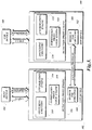
- FIGURE 2 is a block diagram that illustrates further details of the upstream USB extension device 104 and downstream USB extension device 106 illustrated in FIGURE 1 .
- the upstream USB extension device 104 includes an upstream facing port 202
- the downstream USB extension device 106 includes a downstream facing port 204.
- the terms "upstream facing port” and the corresponding acronym “UFP” may be used interchangeably, as may the terms “downstream facing port” and the corresponding acronym “DFP.”
- the upstream USB extension device 104 is interchangeably described as an upstream facing port device or UFP device
- the downstream USB extension device 106 is interchangeably described as a downstream facing port device or DFP device.
- the UFP 202 is configured at least to communicate with the host device 102 via a USB-standard-compliant protocol, and to exchange USB bus traffic and other signals with the DFP 204.
- the DFP 204 is configured at least to communicate with the device 108 via a USB-standard-compliant protocol, and to exchange messages and USB bus traffic with the UFP 202.
- the upstream USB extension device 104 and the downstream USB extension device 106 may contain further components such as a power supply, a status LED, a loudspeaker, an input device for switching between UFP functionality and DFP functionality, and/or the like. Since such components and their functions are familiar to those of ordinary skill in the art, they have not been discussed further herein.
- the upstream facing port 202 of the upstream USB extension device 104 is connected to a downstream facing port of a host device 102, and the downstream facing port 204 of the downstream USB extension device 106 is connected to an upstream facing port of a USB device 108.
- the upstream facing port 202 of the upstream USB extension device 104 may be connected to a downstream facing port other than one provided by a host device 102, such as a downstream facing port of a hub and/or the like.
- the downstream facing port 204 of the downstream USB extension device 106 may be connected to an upstream facing port other than one provided by a USB device 108, such as an upstream facing port of a hub and/or the like.
- the discussion below is primarily in terms of the simple topology illustrated in FIGURE 2 , but one of ordinary skill in the art will recognize that in some embodiments similar techniques may be used in other topologies without departing from the scope of the present disclosure.
- FIGURE 3 is a block diagram that illustrates an exemplary embodiment of a UFP device and a DFP device configured to communicate via an extension medium according to various aspects of the present disclosure.
- a host device 102 is coupled to the UFP device 302 via a USB 3.0 connection.
- the USB 3.0 connection includes a USB 2.0 bus and a SuperSpeed bus.
- the host device 102 may communicate with the UFP device 302 via low speed, full speed, or high speed via the USB 2.0 bus, and may communicate at higher speeds via the SuperSpeed bus (as described in the USB Specifications).
- An illustrated USB device 108 is coupled to the DFP device 304 via a similar USB 3.0 connection.
- USB 3.0 connections are illustrated in FIGURE 3 , in an actual embodiment, one or both of the host device 102 and the USB device 108 may be coupled to the UFP device 302 or the DFP device 304 via only a USB 1.0, 1.1, or 2.0 connection.
- the UFP device 302 and the DFP device 304 each include extension medium transceiver circuitry 310, 312.
- the extension medium transceiver circuitry 310, 312 is configured to establish a connection between the UFP device 302 and the DFP device 304 via an extension medium such as Ethernet, fiber optic cable, and/or any other suitable medium, as described above.
- the extension medium transceiver circuitry 310 of the UFP device 302 receives information transmitted by the host device 102 in a USB format, converts the information to a format and protocol suitable for transmission over the extension medium, and transmits the information to the DFP device 304.
- the extension medium transceiver circuitry 312 of the DFP device 304 receives the information from the UFP device 302, converts the information to a USB format, and transmits the USB-formatted information to the USB device 108.
- a similar process happens in reverse for USB-formatted information transmitted by the USB device 108 to the host device 102 via the DFP device 304 and the UFP device 302.
- Any suitable technique may be used by the extension medium transceiver circuitry 310, 312 to translate and exchange the USB-formatted information, including but not limited to the techniques disclosed in commonly owned U.S. Patent No. 6,381, 666 .
- the UFP device 302 and the DFP device 304 include circuitry for establishing an electrical connection to the host device 102 and USB device 108, respectively.
- This circuitry is configured to establish an electrical connection substantially in accordance with the USB Specifications, such that the host device 102 and the USB device 108 behave as if they are connected directly to a USB-compliant device.
- the circuitry includes receiver termination circuitry, as described in Section 6.8.3, "Receiver Electrical Parameters," of the USB 3.0 Specification.
- the receiver termination circuitry on the UFP device 302 allows receiver detection circuitry at the host device 102 (as described in Section 6.11, "Receiver Detection," of the USB 3.0 Specification) to detect that a SuperSpeed electrical connection has been made to the UFP device 302, and the receiver termination circuitry on the DFP device 304 allows receiver detection circuitry at the USB device 108 to detect that a SuperSpeed electrical connection has been made to the DFP device 304.
- the receiver termination circuitry on the UFP device 302 should reflect the termination state of the USB device 108
- the receiver termination circuitry on the DFP device 304 should reflect the termination state of the host device 102. If one of the host device 102 or the USB device 108 does not support SuperSpeed connections, the receiver termination circuitry on the other side of the extension medium should indicate that this is the case.
- the host device 102 and USB device 108 both support SuperSpeed connections
- the host device 102 and USB device 108 could detect the presence of the SuperSpeed connection to the UFP device 302 and DFP device 304, respectively, as soon as the electrical connection was established by plugging in an associated connector. In many circumstances, this would be problematic, as a connection may not yet be established between the UFP device 302 and the DFP device 304. In such a case, the USB device 108 may expect input via the SuperSpeed connection which the DFP device 304 is not yet ready to provide, and may become stuck in an undesired state.
- the host device 102 may not support SuperSpeed communication, in which case presenting receiver termination by the DFP device 304 would cause the USB device 108 to be incorrectly configured, and vice versa. If a SuperSpeed connection is not available, the host device 102 and the USB device 108 may still communicate via a low speed, full speed, or high speed protocol over the USB 2.0 data connections, but might not do so if receiver termination is inappropriately presented by the UFP device 302 or the DFP device 304.
- the UFP device 302 and DFP device 304 each include a detection proxy engine 306, 308.
- the detection proxy engines 306, 308 include switching circuitry 314, 320, an enumeration engine 316, 322, and a termination proxy logic engine 318.
- the switching circuitry 314 and switching circuitry 320 are configurable to selectively connect or disconnect the receiver termination circuitry from the SuperSpeed conductors provided to the host device 102 and the USB device 108. In an enabled state, the switching circuitry 314, 320 connects the receiver termination circuitry to the respective SuperSpeed conductor, while in a disabled state, the switching circuitry 314, 320 disconnects the receiver termination circuitry from the respective SuperSpeed conductor.
- the enumeration engines 316, 322 are configured to determine whether the host device 102 and USB device 108, respectively, support SuperSpeed communication.
- the termination proxy logic engines 318, 324 are configured to control the switching circuitry 314, 320 and the enumeration engines 316, 322, in order to present receiver termination to the host device 102 and USB device 108 at appropriate times, as described further below.
- engine refers to logic embodied in hardware or software instructions, which can be written in a programming language, such as C, C++, COBOL, JAVATM, PHP, Perl, HTML, CSS, JavaScript, VBScript, ASPX, Microsoft .NETTM languages such as C#, and/or the like.
- An engine may be compiled into executable programs, written in interpreted programming languages, or embodied directly in electronic logic. Engines may be callable from other engines or from themselves.
- the engines described herein refer to logical modules that can be merged with other engines, or can be divided into sub-engines.
- the engines can be stored in any type of computer-readable medium or computer storage device and be stored on and executed by one or more general purpose computers, thus creating a special purpose computer configured to provide the engine.
- the detection proxy engines 306, 308 and/or the extension medium transceiver circuitry 310, 312 may be implemented within one or more logic devices such as PLDs, ASICs, FPGAs, and/or the like.
- the detection proxy engines 306, 308 may be implemented within a computing device having at least one processor and a memory containing computer executable instructions that, if executed by the at least one processor, cause the detection proxy engine 306, 308 to perform the actions discussed below; a dedicated digital hardware device implemented, for example, as a state machine configured to perform the actions described; within an application specific processor; and/or within any other suitable computing device.
- the detection proxy engines 306, 308 may be built into USB-compatible hub circuitry included within the UFP device 302 and/or the DFP device 304. In some embodiments, USB-compatible hub circuitry may be built into the detection proxy engines 306, 308.
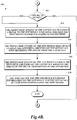
- FIGURES 4A-4D include a flowchart that illustrates an exemplary embodiment of a method of establishing a USB connection between a host device 102 and a USB device 108, according to various aspects of the present disclosure.
- the method 400 relates to establishing a USB connection between a host device 102 coupled to a UFP device 302, and a USB device 108 connected to a DFP device 304.
- a similar method may be used to establish a USB connection between a host device 102 and a hub, between a hub and a USB device 108, between two hubs, or within any other USB topology.
- the method 400 proceeds to block 402, where a termination proxy logic engine 318 of a UFP device 302 disables switching circuitry 314 of the UFP device 302, and a termination proxy logic engine 324 of a DFP device 304 disables switching circuitry 320 of the DFP device 304. Disabling of the switching circuitry 314, 320 will cause the host device 102 to not detect the UFP device 302 as a receiver, and will cause the USB device 108 to not detect the DFP device 304 as a receiver, even if the appropriate electrical connections between the host device 102 and the UFP device 302 or between the USB device 108 and the DFP device 304 are made.
- the host device 102 and the USB device 108 are either not yet electrically coupled to the UFP device 302 and the DFP device 304, are not powered on, or are otherwise not communicatively active.
- one or both of the host device 102 and the USB device 108 may be previously communicatively active and/or communicatively coupled to the UFP device 302 and/or the DFP device 304, and the actions described in block 402 may cause the host device 102 and USB device 108 to behave as if they have been disconnected from the SuperSpeed connection.
- the actions described in block 402 may be performed after detecting a warm reset, a hot reset, or some other disconnection or reconnection of one or both of the SuperSpeed connections.
- the UFP device 302 detects that a connection has been made to a host device 102.
- the UFP device 302 may detect the connection to the host device 102 upon receiving a V BUS signal from the host device 102, as defined in the USB Specifications.
- the method 400 proceeds to block 406, where an enumeration engine 316 of the UFP device 302 determines whether the host device 102 supports SuperSpeed connections.
- the UFP device 302 may utilize receiver detection on a differential pair conductor of the SuperSpeed connection, wherein the differential pair conductor is intended for the transmission of data from the UFP device 302 to the host device 102. This is similar to the receiver detection discussed above for the host device 102 to detect the UFP device 302, but the termination circuitry is present on the host device 102 and the receiver detection circuitry is present on the UFP device 302.
- the UFP device 302 establishes a connection with the DFP device 304 via an extension medium.
- establishing a connection between the UFP device 302 and the DFP device 304 may include performing a suitable extension protocol handshake between the UFP device 302 and the DFP device 304.
- establishing a connection between the UFP device 302 and the DFP device 304 may simply involve detection of a signal transmitted between the UFP device 302 and the DFP device 304.
- the DFP device 304 detects that a connection has been made to a USB device 108.
- the DFP device 302 may detect the connection to the USB device 108 upon receiving a V BUS signal from the USB device 108.
- the UFP device 302 and/or the DFP device 304 may establish a connection to the host device 102 or the USB device 108 and may place that connection in a hold state until the connection between the UFP device 302 and the DFP device 304 is established.
- the UFP device 302 may establish an electrical connection to the host device 102, but may place the connection in a hold state by continuing to leave the switching circuitry 314 disabled.
- the UFP device 302 and the DFP device 304 may establish a mutual connection before detecting a connection from one or both of the host device 102 and the USB device 108.
- the UFP device 302 and the DFP device 304 may detect connections to the host device 102 and USB device 108 at the same time, or in the opposite order as illustrated in FIGURE 4A , without departing from the scope of the present disclosure.
- the method 400 then proceeds to a continuation terminal ("terminal A").
- the method 400 proceeds to block 412, where a determination is made as to whether the UFP device 302 is to assume that the USB device 108 supports SuperSpeed connections.
- the UFP device 302 may be configurable to either assume that the USB device 108 supports SuperSpeed connections, or to not make such an assumption and instead to perform actions to determine whether the USB device 108 supports such connections. In some embodiments, the UFP device 302 may support one path or the other, but not both. If the UFP device 302 is configured to assume that the USB device 108 supports SuperSpeed connections, the result of the determination in block 412 is YES, and the method 400 proceeds to block 414. Otherwise, the result of the determination in block 412 is NO, and the method 400 proceeds to another continuation terminal ("terminal B").
- the termination proxy logic engine 318 of the UFP device 302 transmits a signal to the DFP device 304 indicating whether the host device 102 supports SuperSpeed connections.
- the signal may include a packet or command of an extension protocol used by the UFP device 302 and the DFP device 304 for exchanging data and commands.
- the signal may be a simple electrical or optical signal transmitted over the extension medium, or any other suitable signal for indicating whether the host device 102 supports SuperSpeed connections.
- the termination proxy logic engine 324 of the DFP device 304 selectively enables the switching circuitry 320 of the DFP device 304 upon receiving the signal from the UFP device 302, thereby indicating to the USB device 108 whether it is connected to a host device 102 that supports SuperSpeed communication. If the signal received from the UFP device 302 indicated that the host device 102 does not support SuperSpeed communication, the switching circuitry 320 is not enabled.
- the termination proxy logic engine 318 of the UFP device 302 does not wait for an indication from the DFP device 304 that the USB device 108 supports SuperSpeed connections. Instead, at block 418, the termination proxy logic engine 318 of the UFP device 302 enables the switching circuitry 314 of the UFP device 302 based on the timing of the signal transmitted to the DFP device 304. If the host device 102 does not support SuperSpeed connections, this value may be ignored by the host device 102.
- the enabling of the switching circuitry 314 may be based on an expected time at which the DFP device 304 will enable its switching circuitry 320.
- the termination proxy logic engine 318 may base the expected time on an expected a signal transmission latency, a predetermined delay, and/or any other suitable information, such that the switching circuitry 314 of the UFP device 302 and the switching circuitry 320 of the DFP device 304 are enabled at substantially the same time.
- the termination proxy logic engine 318 of the UFP device 302 may not enable the switching circuitry 314 unless it receives an indication that the USB device 108 is connected to the DFP device 304. In some embodiments, the termination proxy logic engine 318 may enable the switching circuitry 314 whether or not the USB device 108 is connected to the DFP device 304, and will allow the host device 102 to handle any errors that occur due to a lack of responsiveness as it normally would.
- the switching circuitry 320 may be activated by the termination proxy logic engine 324 of the DFP device 304 before the USB device 108 is connected to the DFP device 304, if the DFP device 304 is coupled to a UFP device 302 and host device 102 that supports SuperSpeed connections. In such a case, the USB device 108 would correctly detect the receiver termination at the DFP device 304 upon being connected to the DFP device 304.
- the host device 102 and the USB device 108 exchange information via the UFP device 302 and the DFP device 304 at a USB speed supported by the host device 102. Assuming the host device 102 supports SuperSpeed connections, SuperSpeed information is exchanged between the host device 102 and the USB device 108. If the host device 102 does not support SuperSpeed connections, the host device 102 and the USB device 108 may still exchange information via a low speed, a full speed, or a high speed USB protocol. In some embodiments, the host device 102 and the USB device 108 may exchange information via a low speed, a full speed, or a high speed USB protocol whether or not a SuperSpeed connection is established. The method 400 then proceeds to an end block and terminates.
- the method 400 proceeds to terminal B. From terminal B ( FIGURE 4C ), the method 400 proceeds to another continuation terminal ("terminal C"), and then to block 422, where an enumeration engine 322 of the DFP device 304 determines whether the USB device 108 supports SuperSpeed connections. As discussed above with respect to the UFP device 302 determining whether the host device 102 supports SuperSpeed connections, the enumeration engine 322 may determine whether the USB device 108 supports SuperSpeed connections by checking for a termination circuit at the USB device 108 on a conductive pair configured to transmit SuperSpeed data from the DFP device 304 to the USB device 108.
- the method 400 proceeds to block 426, where the termination proxy logic engine 324 of the DFP device 304 places the SuperSpeed connection to the USB device 108 in a logically disconnected state.
- placing the SuperSpeed connection in the logically disconnected state may include leaving the switching circuitry 320 disabled such that receiver termination is not presented to the USB device 108.
- a "logically disconnected state" may be the Rx.Detect state illustrated in Figure 7-13 of the USB 3.0 Specification.
- the Rx.Detect state is one example of a logically disconnected state, but in other embodiments, other logically disconnected states may be used instead, such as the SS.Inactive state, the SS.Disabled state, or any other suitable state.
- terminal D a continuation terminal
- the method 400 proceeds to block 428, where the termination proxy logic engine 324 of the DFP device 304 transmits a signal to the UFP device 302 indicating whether the USB device 108 supports SuperSpeed connections.
- this signal may include a packet, may be a simple electrical or optical signal, or may be any other suitable signal.
- the termination proxy logic engine 324 of the DFP device 304 receives a signal from the UFP device 302 that may be similar to those discussed above that indicates whether the host device 102 supports SuperSpeed connections, and at block 432, the termination proxy logic engine 324 of the DFP device 304 selectively enables the switching circuitry 320 of the DFP device 304 based on the signal indicating whether the host device 102 supports SuperSpeed connections. Accordingly, the state of the receiver termination circuitry of the DFP device 304 reflects the receiver termination circuitry provided (or not provided) by the host device 102.
- the termination proxy logic engine 318 of the UFP device 302 receives the signal from the DFP device 304 indicating whether the USB device 108 supports SuperSpeed connections.
- the termination proxy logic engine 318 of the UFP device 302 selectively enables the switching circuitry 314 of the UFP device 302 based on the signal indicating whether the USB device 108 supports SuperSpeed connections, such that the state of the receiver termination circuitry of the UFP device 302 reflects the receiver termination circuitry provided (or not provided) by the USB device 108.
- the termination proxy logic engine 324 of the DFP device 304 changes a state of the SuperSpeed connection to the USB device 108, if available, from a logically disconnected state to a logically connected state.
- the termination proxy logic engine 324 may do so by enabling the switching circuitry 320, such that receiver termination is presented to the USB device 108. This may cause the connection to transition from the Rx.Detect state to the Polling state, as illustrated in Figure 7-13 of the USB 3.0 Specification. These states are exemplary only, and in other embodiments, logically disconnected states other than Rx.Detect and/or logically connected states other than Polling may be used. In some embodiments wherein the logically disconnected state is established by disabling the switching circuitry 320, the actions described in block 438 may be omitted if they were performed instead in block 432.
- the host device 102 and the USB device 108 exchange USB information via the UFP device 302 and the DFP device 304. The method 400 then proceeds to an end block and terminates.
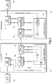
- FIGURE 5 is a block diagram that illustrates another exemplary embodiment of a UFP device and a DFP device according to various aspects of the present disclosure.
- the UFP device 502 and the DFP device 504 each include USB hub circuitry 506, 514, USB redriver circuitry 508, 518, and medium transceiver circuitry 510, 516, respectively.
- the USB hub circuitry 506, 514 may include commercially available USB hubs.
- the USB redriver circuitry 508, 518 may include commercially available USB redrivers that can be enabled and disabled upon receipt of an electrical signal.
- the medium transceiver circuitry 510, 516. may be any suitable transceiver circuitry for accepting a signal from the USB redriver circuitry 508, 518, converting it to a format suitable for transmission, and transmitting it over the extension medium, and vice versa.
- the USB hub circuitry 506 outputs a USB 3.0 termination signal and a USB 3.0 data signal. These signals are provided both to the USB redriver circuitry 508 and the logic circuitry 512.
- the USB redriver circuitry 508 When the USB redriver circuitry 508 is enabled, it provides the termination signal and data signal to the medium transceiver circuitry 510 for transmission to the DFP device 504.
- the medium transceiver circuitry 510 outputs a receive detect (RX Detect) signal and a receive power (RX Power) signal to the logic circuitry 512 based on whether such signals are detected over the extension medium from the DFP device 504.
- the logic circuitry 512 provides enable signals to the USB redriver circuitry 508 and the medium transceiver circuitry 510.
- the medium transceiver circuitry 516 also outputs an RX Detect signal and an RX Power signal to logic circuitry 520 based on whether such signals are detected over the extension medium from the UFP device 502.
- the USB hub circuitry 514 outputs a USB 3.0 termination signal and a USB 3.0 data signal to the USB redriver circuitry 518.
- the USB redriver circuitry 518 when enabled, provides the data signal to the medium transceiver circuitry 516.
- the medium transceiver circuitry 516 when enabled, converts and transmits the signal from the USB redriver circuitry 518 over the extension medium.
- the USB redriver circuitry 508, 518 and the medium transceiver circuitry 510, 516 are not enabled.
- the USB hub circuitry 506 establishes a USB connection to the host device 102.
- the USB hub circuitry 506 begins transmitting the termination signal and the data signal.
- the USB redriver circuitry 508 receives these signals, but does not retransmit them due to the fact that it is not yet enabled.
- the logic circuitry 512 also receives these signals at an AND gate, and once both signals are detected, the logic circuitry 512 provides an enable signal to the medium transceiver circuitry 510.
- the medium transceiver circuitry 510 Upon receiving the enable signal, the medium transceiver circuitry 510 begins transmitting a signal over the extension medium to the medium transceiver circuitry 516 of the DFP device 504.
- the medium transceiver circuitry 516 detects the signal, and begins generating the RX Detect signal. Once the signal has been detected as being of a predetermined power for a predetermined amount of time to indicate a reliable communication connection, the medium transceiver circuitry 516 begins generating the RX Power signal.
- the RX Detect and RX Power signals are provided to the logic circuitry 520 at an AND gate. Once both signals are detected, an enable signal is provided to the medium transceiver circuitry 516 and to a timer of the logic circuitry 520.
- the timer delays for an amount of time intended to compensate for a delay in subsequent steps to be performed at the UFP device 502, and then transmits the termination enable signal to the USB hub circuitry 514 and the enable signal to the USB redriver circuitry 518.
- the termination enable signal causes the USB hub circuitry 514 to present USB 3.0 termination to the USB device 108.
- the medium transceiver circuitry 516 begins transmitting a signal to the medium transceiver circuitry 510 of the UFP device 502. Once the medium transceiver circuitry 510 detects the signal and determines that the power meets one or more thresholds that indicate a stable communication link, the medium transceiver circuitry 510 provides the RX Detect and RX Power signals to the logic circuitry 512 at an AND gate. Once the logic circuitry 512 receives both signals, the logic circuitry 512 provides an enable signal to the USB redriver circuitry 508. The timing compensation at the DFP device 504 is calculated to cause termination to be presented to the USB device 108 at substantially the same time that the USB redriver circuitry 508 is enabled, and the connection between the UFP device 502 and the DFP device 504 is complete.
Landscapes
- Engineering & Computer Science (AREA)
- General Engineering & Computer Science (AREA)
- Theoretical Computer Science (AREA)
- Computer Hardware Design (AREA)
- Physics & Mathematics (AREA)
- General Physics & Mathematics (AREA)
- Information Transfer Systems (AREA)
Claims (13)
- Stromaufwärts gewandte Anschluss-, UFP-Vorrichtung, umfassend:zumindest einen stromaufwärts gewandten Anschluss, der über ein USB-Protokoll mit einer Host-Vorrichtung oder einer Hub-Vorrichtung koppelbar ist; undeine Proxy-Erkennungs-Engine, konfiguriert, um:einen USB-Kommunikationskanal mit einer Host-Vorrichtung oder einer Hub-Vorrichtung einzurichten, die mit dem zumindest einen stromaufwärts gewandten Anschluss gekoppelt ist; undden USB-Kommunikationskanal mit der Host-Vorrichtung oder der Hub-Vorrichtung in einem logisch getrennten Zustand zu halten, bis ein Signal empfangen wird, das darauf hinweist, ob eine USB-Vorrichtung, die mit einer stromabwärts gewandten Anschluss-, DFP-Vorrichtung, verbunden ist, SuperSpeed-Kommunikation unterstützt.
- UFP-Vorrichtung nach Anspruch 1, darüber hinaus einen Erweiterungsmedien-Sendeempfänger umfassend, der konfiguriert ist, um:einen Kommunikationskanal zwischen der UFP-Vorrichtung und der DFP-Vorrichtung einzurichten; unddas Signal von der DFP-Vorrichtung zu empfangen, das darauf hinweist, ob die USB-Vorrichtung SuperSpeed-Kommunikation unterstützt.
- UFP-Vorrichtung nach Anspruch 1 oder 2, wobei die Proxy-Erkennungs-Engine darüber hinaus konfiguriert ist, um:als Reaktion auf den Empfang des Signals, das darauf hinweist, ob die USB-Vorrichtung SuperSpeed-Kommunikation unterstützt, der Host-Vorrichtung oder der Hub-Vorrichtung basierend auf dem Signal selektiv einen Empfänger-Abschluss zu präsentieren.
- UFP-Vorrichtung nach einem der Ansprüche 1 bis 3, wobei die Proxy-Erkennungs-Engine einen USB-Hub-Schaltkreis enthält.
- Stromabwärts gewandte Anschluss-, DFP-Vorrichtung, umfassend:zumindest einen stromabwärts gewandten Anschluss, der über ein USB-Protokoll mit einer USB-Vorrichtung koppelbar ist; undeine Proxy-Erkennungs-Engine, konfiguriert, um:einen USB-Kommunikationskanal mit einer USB-Vorrichtung einzurichten, die mit dem zumindest einen stromabwärts gewandten Anschluss gekoppelt ist; undden USB-Kommunikationskanal mit der USB-Vorrichtung in einem logisch getrennten Zustand zu halten, bis ein Signal empfangen wird, das darauf hinweist, ob eine Host-Vorrichtung oder eine Hub-Vorrichtung, die mit einer stromaufwärts gewandten Anschluss-, UFP-Vorrichtung verbunden ist, SuperSpeed-Kommunikation unterstützt.
- DFP-Vorrichtung nach Anspruch 5, darüber hinaus einen Erweiterungsmedien-Sendeempfänger umfassend, der konfiguriert ist, um:einen Kommunikationskanal zwischen der DFP-Vorrichtung und der UFP-Vorrichtung einzurichten; unddas Signal von der UFP-Vorrichtung zu empfangen, das darauf hinweist, ob die Host-Vorrichtung oder die Hub-Vorrichtung SuperSpeed-Kommunikation unterstützt.
- DFP-Vorrichtung nach Anspruch 5 oder 6, wobei die Proxy-Erkennungs-Engine darüber hinaus konfiguriert ist, um:als Reaktion auf den Empfang des Signals, das darauf hinweist, ob die Host-Vorrichtung oder die Hub-Vorrichtung SuperSpeed-Kommunikation unterstützt, der USB-Vorrichtung basierend auf dem Signal selektiv einen Empfänger-Abschluss zu präsentieren.
- DFP-Vorrichtung nach einem der Ansprüche 5 bis 7, wobei die Proxy-Erkennungs-Engine einen USB-Hub enthält.
- Verfahren zur Einrichtung einer USB-Kommunikation zwischen einer Host-Vorrichtung und einer USB-Vorrichtung, die über eine stromaufwärts gewandte Anschluss-, UFP-Vorrichtung, mit der Host-Vorrichtung gekoppelt ist, und einer stromabwärts gewandten Anschluss-, DFP-Vorrichtung, die mit der USB-Vorrichtung gekoppelt ist, wobei das Verfahren umfasst:Einrichtung einer Verbindung zwischen der USB-Vorrichtung und der DFP-Vorrichtung;Halten der Verbindung in einem logisch getrennten Zustand;Einrichtung eines Kommunikationskanals zwischen der UFP-Vorrichtung und der DFP-Vorrichtung;undSelektive Aktivierung eines Umschaltkreises der DFP-Vorrichtung basierend auf einer Bestimmung, ob die Host-Vorrichtung SuperSpeed-Kommunikation unterstützt wobei die Aktivierung eines Umschaltkreises der DFP-Vorrichtung den Empfänger-Abschlussschaltungskomplex der DFP-Vorrichtung dazu veranlasst mit einem Leiter gekoppelt zu werden, der zur Übertragung von Daten von der USB-Vorrichtung zur DFP-Vorrichtung konfiguriert ist.
- Verfahren nach Anspruch 9, wobei die Bestimmung, ob die Host-Vorrichtung SuperSpeed-Kommunikation unterstützt enthält:Durchführen einer Empfängererfassung auf einem Leiter, der zur Übertragung von Daten von der UFP-Vorrichtung zur Host-Vorrichtung konfiguriert ist.
- Verfahren nach Anspruch 9 oder 10, darüber hinaus umfassend:Übertragen, durch die UFP-Vorrichtung zur DFP-Vorrichtung, eines Signals, das darauf hinweist, ob die Host-Vorrichtung SuperSpeed-Kommunikation unterstützt.
- Verfahren zur Einrichtung einer USB-Kommunikation zwischen einer Host-Vorrichtung und einer USB-Vorrichtung, die über eine stromaufwärts gewandte Anschluss-, UFP-Vorrichtung mit der Host-Vorrichtung verbunden ist, und einer stromabwärts gewandten Anschluss-, DFP-Vorrichtung, die mit der USB-Vorrichtung verbunden ist, wobei das Verfahren umfasst:Bestimmung, ob die Host-Vorrichtung SuperSpeed-Kommunikation unterstützt;Einrichtung eines Kommunikationskanals zwischen der UFP-Vorrichtung und der DFP-Vorrichtung;Übertragung, durch die UFP-Vorrichtung zur DFP-Vorrichtung, eines Signals, das darauf hinweist, ob die Host-Vorrichtung SuperSpeed-Kommunikation unterstützt;Selektive Aktivierung eines Empfänger-Abschlusses an der DFP-Vorrichtung basierend auf dem Inhalt des Signals; undSelektive Aktivierung eines Empfänger-Abschlusses an der UFP-Vorrichtung, darauf basierend, ob die Host-Vorrichtung SuperSpeed-Kommunikation zu einer Zeit basierend auf einer Zeit der Übertragung des Signals zur DFP-Vorrichtung unterstützt.
- Verfahren nach Anspruch 12, wobei die Bestimmung, ob die Host-Vorrichtung SuperSpeed-Kommunikation unterstützt enthält:Durchführen einer Empfängererfassung auf einem Leiter, der zur Übertragung von Daten von der UFP-Vorrichtung zur Host-Vorrichtung konfiguriert ist.
Applications Claiming Priority (3)
| Application Number | Priority Date | Filing Date | Title |
|---|---|---|---|
| US201261740133P | 2012-12-20 | 2012-12-20 | |
| US13/791,619 US20130254440A1 (en) | 2012-03-20 | 2013-03-08 | Devices and methods for transmitting usb termination signals over extension media |
| PCT/CA2013/001059 WO2014094128A1 (en) | 2012-12-20 | 2013-12-19 | Devices and methods for transmitting usb termination signals over extension media |
Publications (3)
| Publication Number | Publication Date |
|---|---|
| EP2936760A1 EP2936760A1 (de) | 2015-10-28 |
| EP2936760A4 EP2936760A4 (de) | 2016-07-27 |
| EP2936760B1 true EP2936760B1 (de) | 2017-08-02 |
Family
ID=50977461
Family Applications (1)
| Application Number | Title | Priority Date | Filing Date |
|---|---|---|---|
| EP13863974.5A Active EP2936760B1 (de) | 2012-12-20 | 2013-12-19 | Vorrichtungen und verfahren zur übertragung von usb-abschlusssignalen über verlängerungsmedien |
Country Status (3)
| Country | Link |
|---|---|
| EP (1) | EP2936760B1 (de) |
| CA (1) | CA2894619A1 (de) |
| WO (1) | WO2014094128A1 (de) |
Families Citing this family (1)
| Publication number | Priority date | Publication date | Assignee | Title |
|---|---|---|---|---|
| US10051205B1 (en) * | 2017-08-31 | 2018-08-14 | Icron Technologies Corporation | Devices, systems, and methods for instant video switching in an extension environment |
Family Cites Families (7)
| Publication number | Priority date | Publication date | Assignee | Title |
|---|---|---|---|---|
| CN100397372C (zh) * | 1998-01-22 | 2008-06-25 | 英纳瑞公司 | 用于通用数据交换网关的方法和装置 |
| EP1155370B1 (de) * | 1999-02-19 | 2003-05-02 | Icron Systems Inc. | Verfahren und vorrichtung zur erweiterung des usb-protokollbereichs |
| US7933295B2 (en) * | 1999-04-13 | 2011-04-26 | Broadcom Corporation | Cable modem with voice processing capability |
| US7028133B1 (en) * | 1999-04-30 | 2006-04-11 | Daniel Kelvin Jackson | Method and apparatus for extending communications over USB |
| US8347341B2 (en) * | 2006-03-16 | 2013-01-01 | Time Warner Cable Inc. | Methods and apparatus for centralized content and data delivery |
| TWI321731B (en) * | 2006-09-18 | 2010-03-11 | Quanta Comp Inc | Device connection system and device connection method |
| TWI465784B (zh) * | 2011-11-23 | 2014-12-21 | Via Tech Inc | 主動型光纖纜線與電子裝置 |
-
2013
- 2013-12-19 CA CA2894619A patent/CA2894619A1/en not_active Abandoned
- 2013-12-19 EP EP13863974.5A patent/EP2936760B1/de active Active
- 2013-12-19 WO PCT/CA2013/001059 patent/WO2014094128A1/en active Application Filing
Non-Patent Citations (1)
| Title |
|---|
| None * |
Also Published As
| Publication number | Publication date |
|---|---|
| CA2894619A1 (en) | 2014-06-26 |
| EP2936760A1 (de) | 2015-10-28 |
| WO2014094128A1 (en) | 2014-06-26 |
| EP2936760A4 (de) | 2016-07-27 |
Similar Documents
| Publication | Publication Date | Title |
|---|---|---|
| US20130254440A1 (en) | Devices and methods for transmitting usb termination signals over extension media | |
| US9355057B2 (en) | Universal serial bus repeater | |
| EP2867780B1 (de) | Vorrichtungstrennungserkennung | |
| US9239810B2 (en) | Low power universal serial bus | |
| US8977789B2 (en) | Device connect detection | |
| EP2842293B1 (de) | Timer-einstellung der usb-3.0-verbindungssicherungsschicht zur vergrösserung des abstands | |
| US9864607B2 (en) | Methods and physical computer-readable storage media for initiating re-enumeration of USB 3.0 compatible devices | |
| US9940277B2 (en) | Multi-channel peripheral interconnect supporting simultaneous video and bus protocols | |
| JP2013192223A (ja) | アクティブ光ケーブルコネクタプラグ及びこれを用いたアクティブ光ケーブル | |
| US8788734B2 (en) | Methods and devices for universal serial bus port event extension | |
| EP2972919B1 (de) | Vorrichtungen und verfahren zur aktivierung einer usb-kommunikation über erweiterungsmedien | |
| EP2936760B1 (de) | Vorrichtungen und verfahren zur übertragung von usb-abschlusssignalen über verlängerungsmedien | |
| US20140258584A1 (en) | Bus relay apparatus, integrated circuit apparatus, cable, connector, electronic appliance, and bus relay method |
Legal Events
| Date | Code | Title | Description |
|---|---|---|---|
| PUAI | Public reference made under article 153(3) epc to a published international application that has entered the european phase |
Free format text: ORIGINAL CODE: 0009012 |
|
| 17P | Request for examination filed |
Effective date: 20150714 |
|
| AK | Designated contracting states |
Kind code of ref document: A1 Designated state(s): AL AT BE BG CH CY CZ DE DK EE ES FI FR GB GR HR HU IE IS IT LI LT LU LV MC MK MT NL NO PL PT RO RS SE SI SK SM TR |
|
| AX | Request for extension of the european patent |
Extension state: BA ME |
|
| DAX | Request for extension of the european patent (deleted) | ||
| A4 | Supplementary search report drawn up and despatched |
Effective date: 20160628 |
|
| RIC1 | Information provided on ipc code assigned before grant |
Ipc: G06F 13/40 20060101AFI20160622BHEP |
|
| REG | Reference to a national code |
Ref country code: DE Ref legal event code: R079 Ref document number: 602013024594 Country of ref document: DE Free format text: PREVIOUS MAIN CLASS: H04L0029020000 Ipc: G06F0013400000 |
|
| GRAP | Despatch of communication of intention to grant a patent |
Free format text: ORIGINAL CODE: EPIDOSNIGR1 |
|
| STAA | Information on the status of an ep patent application or granted ep patent |
Free format text: STATUS: GRANT OF PATENT IS INTENDED |
|
| RIC1 | Information provided on ipc code assigned before grant |
Ipc: G06F 13/40 20060101AFI20170209BHEP |
|
| INTG | Intention to grant announced |
Effective date: 20170227 |
|
| GRAS | Grant fee paid |
Free format text: ORIGINAL CODE: EPIDOSNIGR3 |
|
| GRAA | (expected) grant |
Free format text: ORIGINAL CODE: 0009210 |
|
| STAA | Information on the status of an ep patent application or granted ep patent |
Free format text: STATUS: THE PATENT HAS BEEN GRANTED |
|
| AK | Designated contracting states |
Kind code of ref document: B1 Designated state(s): AL AT BE BG CH CY CZ DE DK EE ES FI FR GB GR HR HU IE IS IT LI LT LU LV MC MK MT NL NO PL PT RO RS SE SI SK SM TR |
|
| REG | Reference to a national code |
Ref country code: CH Ref legal event code: EP Ref country code: AT Ref legal event code: REF Ref document number: 915199 Country of ref document: AT Kind code of ref document: T Effective date: 20170815 |
|
| REG | Reference to a national code |
Ref country code: IE Ref legal event code: FG4D |
|
| REG | Reference to a national code |
Ref country code: DE Ref legal event code: R096 Ref document number: 602013024594 Country of ref document: DE |
|
| REG | Reference to a national code |
Ref country code: FR Ref legal event code: PLFP Year of fee payment: 5 |
|
| REG | Reference to a national code |
Ref country code: NL Ref legal event code: MP Effective date: 20170802 |
|
| REG | Reference to a national code |
Ref country code: AT Ref legal event code: MK05 Ref document number: 915199 Country of ref document: AT Kind code of ref document: T Effective date: 20170802 |
|
| REG | Reference to a national code |
Ref country code: LT Ref legal event code: MG4D |
|
| PG25 | Lapsed in a contracting state [announced via postgrant information from national office to epo] |
Ref country code: HR Free format text: LAPSE BECAUSE OF FAILURE TO SUBMIT A TRANSLATION OF THE DESCRIPTION OR TO PAY THE FEE WITHIN THE PRESCRIBED TIME-LIMIT Effective date: 20170802 Ref country code: SE Free format text: LAPSE BECAUSE OF FAILURE TO SUBMIT A TRANSLATION OF THE DESCRIPTION OR TO PAY THE FEE WITHIN THE PRESCRIBED TIME-LIMIT Effective date: 20170802 Ref country code: FI Free format text: LAPSE BECAUSE OF FAILURE TO SUBMIT A TRANSLATION OF THE DESCRIPTION OR TO PAY THE FEE WITHIN THE PRESCRIBED TIME-LIMIT Effective date: 20170802 Ref country code: LT Free format text: LAPSE BECAUSE OF FAILURE TO SUBMIT A TRANSLATION OF THE DESCRIPTION OR TO PAY THE FEE WITHIN THE PRESCRIBED TIME-LIMIT Effective date: 20170802 Ref country code: NO Free format text: LAPSE BECAUSE OF FAILURE TO SUBMIT A TRANSLATION OF THE DESCRIPTION OR TO PAY THE FEE WITHIN THE PRESCRIBED TIME-LIMIT Effective date: 20171102 Ref country code: AT Free format text: LAPSE BECAUSE OF FAILURE TO SUBMIT A TRANSLATION OF THE DESCRIPTION OR TO PAY THE FEE WITHIN THE PRESCRIBED TIME-LIMIT Effective date: 20170802 Ref country code: NL Free format text: LAPSE BECAUSE OF FAILURE TO SUBMIT A TRANSLATION OF THE DESCRIPTION OR TO PAY THE FEE WITHIN THE PRESCRIBED TIME-LIMIT Effective date: 20170802 |
|
| PG25 | Lapsed in a contracting state [announced via postgrant information from national office to epo] |
Ref country code: ES Free format text: LAPSE BECAUSE OF FAILURE TO SUBMIT A TRANSLATION OF THE DESCRIPTION OR TO PAY THE FEE WITHIN THE PRESCRIBED TIME-LIMIT Effective date: 20170802 Ref country code: LV Free format text: LAPSE BECAUSE OF FAILURE TO SUBMIT A TRANSLATION OF THE DESCRIPTION OR TO PAY THE FEE WITHIN THE PRESCRIBED TIME-LIMIT Effective date: 20170802 Ref country code: IS Free format text: LAPSE BECAUSE OF FAILURE TO SUBMIT A TRANSLATION OF THE DESCRIPTION OR TO PAY THE FEE WITHIN THE PRESCRIBED TIME-LIMIT Effective date: 20171202 Ref country code: PL Free format text: LAPSE BECAUSE OF FAILURE TO SUBMIT A TRANSLATION OF THE DESCRIPTION OR TO PAY THE FEE WITHIN THE PRESCRIBED TIME-LIMIT Effective date: 20170802 Ref country code: BG Free format text: LAPSE BECAUSE OF FAILURE TO SUBMIT A TRANSLATION OF THE DESCRIPTION OR TO PAY THE FEE WITHIN THE PRESCRIBED TIME-LIMIT Effective date: 20171102 Ref country code: RS Free format text: LAPSE BECAUSE OF FAILURE TO SUBMIT A TRANSLATION OF THE DESCRIPTION OR TO PAY THE FEE WITHIN THE PRESCRIBED TIME-LIMIT Effective date: 20170802 Ref country code: GR Free format text: LAPSE BECAUSE OF FAILURE TO SUBMIT A TRANSLATION OF THE DESCRIPTION OR TO PAY THE FEE WITHIN THE PRESCRIBED TIME-LIMIT Effective date: 20171103 |
|
| PG25 | Lapsed in a contracting state [announced via postgrant information from national office to epo] |
Ref country code: DK Free format text: LAPSE BECAUSE OF FAILURE TO SUBMIT A TRANSLATION OF THE DESCRIPTION OR TO PAY THE FEE WITHIN THE PRESCRIBED TIME-LIMIT Effective date: 20170802 Ref country code: CZ Free format text: LAPSE BECAUSE OF FAILURE TO SUBMIT A TRANSLATION OF THE DESCRIPTION OR TO PAY THE FEE WITHIN THE PRESCRIBED TIME-LIMIT Effective date: 20170802 Ref country code: RO Free format text: LAPSE BECAUSE OF FAILURE TO SUBMIT A TRANSLATION OF THE DESCRIPTION OR TO PAY THE FEE WITHIN THE PRESCRIBED TIME-LIMIT Effective date: 20170802 |
|
| REG | Reference to a national code |
Ref country code: DE Ref legal event code: R097 Ref document number: 602013024594 Country of ref document: DE |
|
| PG25 | Lapsed in a contracting state [announced via postgrant information from national office to epo] |
Ref country code: SM Free format text: LAPSE BECAUSE OF FAILURE TO SUBMIT A TRANSLATION OF THE DESCRIPTION OR TO PAY THE FEE WITHIN THE PRESCRIBED TIME-LIMIT Effective date: 20170802 Ref country code: IT Free format text: LAPSE BECAUSE OF FAILURE TO SUBMIT A TRANSLATION OF THE DESCRIPTION OR TO PAY THE FEE WITHIN THE PRESCRIBED TIME-LIMIT Effective date: 20170802 Ref country code: SK Free format text: LAPSE BECAUSE OF FAILURE TO SUBMIT A TRANSLATION OF THE DESCRIPTION OR TO PAY THE FEE WITHIN THE PRESCRIBED TIME-LIMIT Effective date: 20170802 Ref country code: EE Free format text: LAPSE BECAUSE OF FAILURE TO SUBMIT A TRANSLATION OF THE DESCRIPTION OR TO PAY THE FEE WITHIN THE PRESCRIBED TIME-LIMIT Effective date: 20170802 |
|
| PLBE | No opposition filed within time limit |
Free format text: ORIGINAL CODE: 0009261 |
|
| STAA | Information on the status of an ep patent application or granted ep patent |
Free format text: STATUS: NO OPPOSITION FILED WITHIN TIME LIMIT |
|
| 26N | No opposition filed |
Effective date: 20180503 |
|
| REG | Reference to a national code |
Ref country code: CH Ref legal event code: PL |
|
| PG25 | Lapsed in a contracting state [announced via postgrant information from national office to epo] |
Ref country code: SI Free format text: LAPSE BECAUSE OF FAILURE TO SUBMIT A TRANSLATION OF THE DESCRIPTION OR TO PAY THE FEE WITHIN THE PRESCRIBED TIME-LIMIT Effective date: 20170802 |
|
| REG | Reference to a national code |
Ref country code: IE Ref legal event code: MM4A |
|
| PG25 | Lapsed in a contracting state [announced via postgrant information from national office to epo] |
Ref country code: MT Free format text: LAPSE BECAUSE OF NON-PAYMENT OF DUE FEES Effective date: 20171219 Ref country code: LU Free format text: LAPSE BECAUSE OF NON-PAYMENT OF DUE FEES Effective date: 20171219 |
|
| REG | Reference to a national code |
Ref country code: BE Ref legal event code: MM Effective date: 20171231 |
|
| PG25 | Lapsed in a contracting state [announced via postgrant information from national office to epo] |
Ref country code: IE Free format text: LAPSE BECAUSE OF NON-PAYMENT OF DUE FEES Effective date: 20171219 |
|
| PG25 | Lapsed in a contracting state [announced via postgrant information from national office to epo] |
Ref country code: CH Free format text: LAPSE BECAUSE OF NON-PAYMENT OF DUE FEES Effective date: 20171231 Ref country code: LI Free format text: LAPSE BECAUSE OF NON-PAYMENT OF DUE FEES Effective date: 20171231 Ref country code: BE Free format text: LAPSE BECAUSE OF NON-PAYMENT OF DUE FEES Effective date: 20171231 |
|
| PG25 | Lapsed in a contracting state [announced via postgrant information from national office to epo] |
Ref country code: HU Free format text: LAPSE BECAUSE OF FAILURE TO SUBMIT A TRANSLATION OF THE DESCRIPTION OR TO PAY THE FEE WITHIN THE PRESCRIBED TIME-LIMIT; INVALID AB INITIO Effective date: 20131219 Ref country code: MC Free format text: LAPSE BECAUSE OF FAILURE TO SUBMIT A TRANSLATION OF THE DESCRIPTION OR TO PAY THE FEE WITHIN THE PRESCRIBED TIME-LIMIT Effective date: 20170802 |
|
| PG25 | Lapsed in a contracting state [announced via postgrant information from national office to epo] |
Ref country code: CY Free format text: LAPSE BECAUSE OF FAILURE TO SUBMIT A TRANSLATION OF THE DESCRIPTION OR TO PAY THE FEE WITHIN THE PRESCRIBED TIME-LIMIT Effective date: 20170802 |
|
| PG25 | Lapsed in a contracting state [announced via postgrant information from national office to epo] |
Ref country code: MK Free format text: LAPSE BECAUSE OF FAILURE TO SUBMIT A TRANSLATION OF THE DESCRIPTION OR TO PAY THE FEE WITHIN THE PRESCRIBED TIME-LIMIT Effective date: 20170802 |
|
| PG25 | Lapsed in a contracting state [announced via postgrant information from national office to epo] |
Ref country code: TR Free format text: LAPSE BECAUSE OF FAILURE TO SUBMIT A TRANSLATION OF THE DESCRIPTION OR TO PAY THE FEE WITHIN THE PRESCRIBED TIME-LIMIT Effective date: 20170802 |
|
| PG25 | Lapsed in a contracting state [announced via postgrant information from national office to epo] |
Ref country code: PT Free format text: LAPSE BECAUSE OF FAILURE TO SUBMIT A TRANSLATION OF THE DESCRIPTION OR TO PAY THE FEE WITHIN THE PRESCRIBED TIME-LIMIT Effective date: 20170802 |
|
| PG25 | Lapsed in a contracting state [announced via postgrant information from national office to epo] |
Ref country code: AL Free format text: LAPSE BECAUSE OF FAILURE TO SUBMIT A TRANSLATION OF THE DESCRIPTION OR TO PAY THE FEE WITHIN THE PRESCRIBED TIME-LIMIT Effective date: 20170802 |
|
| PGFP | Annual fee paid to national office [announced via postgrant information from national office to epo] |
Ref country code: GB Payment date: 20231121 Year of fee payment: 11 |
|
| PGFP | Annual fee paid to national office [announced via postgrant information from national office to epo] |
Ref country code: FR Payment date: 20231122 Year of fee payment: 11 Ref country code: DE Payment date: 20231121 Year of fee payment: 11 |