EP2936498B1 - Entrainment-reducing assembly, system including the assembly, and method of reducing entrainment of gases with the assembly - Google Patents
Entrainment-reducing assembly, system including the assembly, and method of reducing entrainment of gases with the assembly Download PDFInfo
- Publication number
- EP2936498B1 EP2936498B1 EP13815335.8A EP13815335A EP2936498B1 EP 2936498 B1 EP2936498 B1 EP 2936498B1 EP 13815335 A EP13815335 A EP 13815335A EP 2936498 B1 EP2936498 B1 EP 2936498B1
- Authority
- EP
- European Patent Office
- Prior art keywords
- deflector
- entrainment
- liquid
- suction structure
- container
- Prior art date
- Legal status (The legal status is an assumption and is not a legal conclusion. Google has not performed a legal analysis and makes no representation as to the accuracy of the status listed.)
- Active
Links
Images


Classifications
-
- B—PERFORMING OPERATIONS; TRANSPORTING
- B65—CONVEYING; PACKING; STORING; HANDLING THIN OR FILAMENTARY MATERIAL
- B65D—CONTAINERS FOR STORAGE OR TRANSPORT OF ARTICLES OR MATERIALS, e.g. BAGS, BARRELS, BOTTLES, BOXES, CANS, CARTONS, CRATES, DRUMS, JARS, TANKS, HOPPERS, FORWARDING CONTAINERS; ACCESSORIES, CLOSURES, OR FITTINGS THEREFOR; PACKAGING ELEMENTS; PACKAGES
- B65D90/00—Component parts, details or accessories for large containers
- B65D90/22—Safety features
-
- G—PHYSICS
- G21—NUCLEAR PHYSICS; NUCLEAR ENGINEERING
- G21C—NUCLEAR REACTORS
- G21C9/00—Emergency protection arrangements structurally associated with the reactor, e.g. safety valves provided with pressure equalisation devices
- G21C9/004—Pressure suppression
- G21C9/012—Pressure suppression by thermal accumulation or by steam condensation, e.g. ice condensers
-
- B—PERFORMING OPERATIONS; TRANSPORTING
- B01—PHYSICAL OR CHEMICAL PROCESSES OR APPARATUS IN GENERAL
- B01D—SEPARATION
- B01D29/00—Filters with filtering elements stationary during filtration, e.g. pressure or suction filters, not covered by groups B01D24/00 - B01D27/00; Filtering elements therefor
- B01D29/01—Filters with filtering elements stationary during filtration, e.g. pressure or suction filters, not covered by groups B01D24/00 - B01D27/00; Filtering elements therefor with flat filtering elements
-
- G—PHYSICS
- G21—NUCLEAR PHYSICS; NUCLEAR ENGINEERING
- G21C—NUCLEAR REACTORS
- G21C15/00—Cooling arrangements within the pressure vessel containing the core; Selection of specific coolants
- G21C15/18—Emergency cooling arrangements; Removing shut-down heat
-
- Y—GENERAL TAGGING OF NEW TECHNOLOGICAL DEVELOPMENTS; GENERAL TAGGING OF CROSS-SECTIONAL TECHNOLOGIES SPANNING OVER SEVERAL SECTIONS OF THE IPC; TECHNICAL SUBJECTS COVERED BY FORMER USPC CROSS-REFERENCE ART COLLECTIONS [XRACs] AND DIGESTS
- Y02—TECHNOLOGIES OR APPLICATIONS FOR MITIGATION OR ADAPTATION AGAINST CLIMATE CHANGE
- Y02E—REDUCTION OF GREENHOUSE GAS [GHG] EMISSIONS, RELATED TO ENERGY GENERATION, TRANSMISSION OR DISTRIBUTION
- Y02E30/00—Energy generation of nuclear origin
- Y02E30/30—Nuclear fission reactors
Definitions
- the present disclosure relates to the reduction or prevention of the entrainment of gases into the suction of a pump during a loss of coolant accident (LOCA).
- LOCA loss of coolant accident
- LOCA Loss of Coolant Accident
- ECCS Emergency Core Cooling System
- condensable gases e.g., steam
- non-condensable gases e.g., nitrogen (N 2 )
- An Emergency Core Cooling System (ECCS) pump may be used to maintain the suppression pool at an acceptable level by suctioning excess liquid from the suppression pool and supplying the excess liquid to the reactor core.
- the non-condensable gases may become entrained along with the liquid into the suction of the Emergency Core Cooling System (ECCS) pump, thereby causing loss of suction and decreased flow to the reactor core.
- the presence of non-condensable gases within the Emergency Core Cooling System (ECCS) pump causes cavitation and pump damage, which poses additional safety hazards.
- JP2002 168985 discloses a nuclear reactor with a venting arrangement connecting the reactor's drywell to its wetwell.
- a suction structure extends into the lower portion of the wetwell.
- tubular structures are arranged that shield the suction structure from bubbles of uncondensed gases.
- the present disclosure describes various devices, assemblies, systems, and methods for preventing pumps (e.g., Emergency Core Cooling System (ECCS) pumps) from receiving relatively large quantities of entrained gas in the suction piping, which would cause cavitation and ultimately result in the failure of the pump.
- pumps e.g., Emergency Core Cooling System (ECCS) pumps
- the teachings herein also promote the mitigation or prevention of non-condensable gases from reaching the suction strainers within the wetwell.
- Specially-designed deflector shields or baffles may be arranged between the drywell-to-wetwell vent downcomer and the Emergency Core Cooling System (ECCS) pump suction strainer.
- An entrainment-reducing assembly may include a container configured to hold a liquid.
- the container may include an upper portion and a lower portion.
- a venting arrangement may extend into the container.
- the venting arrangement may be configured to direct gases into the container.
- a suction structure may extend into the lower portion of the container.
- the suction structure may be configured to carry out an extraction of the liquid from the container.
- a deflector may be disposed between the suction structure and the venting arrangement within the container. The deflector may be configured to reduce the entrainment of uncondensed gases during the extraction of the liquid.
- a reactor system may include a first container and a second container.
- the first container may define a drywell therein.
- the second container may define a wetwell therein.
- the second container may include an upper portion and a lower portion.
- a venting arrangement may connect the drywell to the wetwell.
- the venting arrangement may include a proximal end extending into the drywell and a distal end extending into the upper portion of the wetwell.
- a suction structure may extend into the lower portion of the wetwell.
- a deflector may be disposed between the suction structure and the distal end of the venting arrangement within the second container.
- a method of reducing entrainment may include discharging gases from a venting arrangement into a liquid.
- the method may additionally include alleviating an elevated level of the liquid resulting from condensing gases by performing an extraction of the liquid with a suction structure.
- the method may further include shielding the suction structure from the entrainment of uncondensed gases in the liquid with a deflector during the extraction of the liquid.
- FIG. 1 is a simplified, cross-sectional view of a reactor system.
- FIG. 2 is cross-sectional view of an entrainment-reducing assembly that may be used in the reactor system of FIG. 1 .
- FIG. 3 is a cross-sectional view of a deflector according to a non-limiting embodiment that may be used in the entrainment-reducing assembly of FIG. 2 .
- FIG. 4A is a perspective view of another deflector that may be used in the entrainment-reducing assembly of FIG. 2 .
- FIG. 4B is a plan view of the deflector of FIG. 4A .
- FIG. 5A is a perspective view of another deflector that may be used in the entrainment-reducing assembly of FIG. 2 .
- FIG. 5B is a plan view of the deflector of FIG. 5A .
- FIG. 6A is a perspective view of another deflector that may be used in the entrainment-reducing assembly of FIG. 2 .
- FIG. 6B is a plan view of the deflector of FIG. 6A .
- FIG. 7A is a perspective view of another deflector that may be used in the entrainment-reducing assembly of FIG. 2 .
- FIG. 7B is a plan view of the deflector of FIG. 7A .
- FIG. 8A is a perspective view of another deflector that may be used in the entramment-reducing assembly of FIG. 2 .
- FIG. 8B is a plan view of the deflector of FIG. 8A .
- first, second, third, etc. may be used herein to describe various elements, components, regions, layers and/or sections, these elements, components, regions, layers, and/or sections should not be limited by these terms. These terms are only used to distinguish one element, component, region, layer, or section from another region, layer, or section. Thus, a first element, component, region, layer, or section discussed below could be termed a second element, component, region, layer, or section without departing from the teachings of example embodiments.
- spatially relative terms e.g., "beneath,” “below,” “lower,” “above,” “upper,” and the like
- the spatially relative terms are intended to encompass different orientations of the device in use or operation in addition to the orientation depicted in the figures. For example, if the device in the figures is turned over, elements described as “below” or “beneath” other elements or features would then be oriented “above” the other elements or features. Thus, the term “below” may encompass both an orientation of above and below.
- the device may be otherwise oriented (rotated 90 degrees or at other orientations) and the spatially relative descriptors used herein interpreted accordingly.
- Example embodiments are described herein with reference to cross-sectional illustrations that are schematic illustrations of idealized embodiments (and intermediate structures) of example embodiments. As such, variations from the shapes of the illustrations as a result, for example, of manufacturing techniques and/or tolerances, are to be expected. Thus, example embodiments should not be construed as limited to the shapes of regions illustrated herein but are to include deviations in shapes that result, for example, from manufacturing. For example, an implanted region illustrated as a rectangle will, typically, have rounded or curved features and/or a gradient of implant concentration at its edges rather than a binary change from implanted to non-implanted region.
- a buried region formed by implantation may result in some implantation in the region between the buried region and the surface through which the implantation takes place.
- the regions illustrated in the figures are schematic in nature and their shapes are not intended to illustrate the actual shape of a region of a device and are not intended to limit the scope of example embodiments.
- Various embodiments of the present disclosure relate to devices and assemblies, which when used inside a nuclear reactor (e.g., Boiling Water Reactor (BWR) Mark I or Mark II wetwells (torus)), will mitigate or solve the issue of "loss of suction" to Emergency Core Cooling System (ECCS) pumps due to the entrainment of steam and/or non-condensable gases during a Loss of Coolant Accident (LOCA) in the drywell.
- Various embodiments of the present disclosure also relate to systems and methods for reducing the entrainment of gases.
- Boiling Water Reactor BWR
- PWR Pressurized Water Reactor
- teachings herein may be applied to non-reactor settings.
- the devices, assemblies, systems, and methods may be used in other situations in which a suction is taken from a large reservoir of liquid (e.g., water), whereupon a large injection of non-condensable gases could result in these gases being entrained or swept into the suction pipe, thereby causing the downstream pump to fail.
- FIG. 1 is a simplified, cross-sectional view of a reactor system.
- a reactor system 100 includes a first container 102 defining a drywell 104 and a second container 108 defining a wetwell 110.
- a reactor pressure vessel 106 is situated within the drywell 104.
- a body of liquid 112 e.g., suppression pool
- the drywell 104 is connected to the wetwell 110 via a venting arrangement 114.
- the present disclosure details the mitigation or prevention of gases from being entrained in the suction of Emergency Core Cooling System (ECCS) pumps. Such mitigation or prevention may improve the safety operation and availability of the Emergency Core Cooling System (ECCS) pumps during a Loss of Coolant Accident (LOCA).
- LOCA Loss of Coolant Accident
- a relatively large Loss of Coolant Accident (LOCA) may force gas into the Emergency Core Cooling System (ECCS) piping.
- LOCA Loss of Coolant Accident
- a relatively large gas entrainment may lead to gas entering an Emergency Core Cooling System (ECCS) pump, resulting in pump damage from cavitation and reduced flow (if any flow at all) to the reactor core. Consequently, the ability of the Emergency Core Cooling System (ECCS) pumps to maintain the proper water level in the reactor core may be affected. That being said, the present disclosure is directed to mitigating or preventing the possibility of gas reaching the suction of the Emergency Core Cooling System (ECCS) piping.
- a centrifugal pump is used in the Emergency Core Cooling Systems (ECCS) of Boiling Water Reactors (BWR) and Pressurized Water Reactors (PWR).
- ECCS Emergency Core Cooling Systems
- PWR Boiling Water Reactors
- PWR Pressurized Water Reactors
- NPSH net positive suction head
- a centrifugal pump does not have a sufficient net positive suction head (NPSH), then low or no flow, pump wear, and in the worst case, seizing of the pump will result.
- gases e.g., non-condensable nitrogen, which was previously used to inert the drywell, and steam, resulting from the flashing flow from a design basis line break
- ECCS Emergency Core Cooling System
- an Emergency Core Cooling System ECCS
- FIG. 2 is cross-sectional view of an entrainment-reducing assembly that may be used in the reactor system of FIG. 1 .
- the entrainment-reducing assembly of FIG. 2 is shown in connection with a Boiling Water Reactor (BWR) Mark I suppression pool, it should be understood that example set-ups are not limited thereto.
- BWR Boiling Water Reactor
- the entrainment-reducing assembly 200 includes the second container 108, which defines the wetwell 110 and holds the body of liquid 112 (e.g., suppression pool of water) therein.
- the venting arrangement 114 connects the drywell 104 ( FIG. 1 ) to the wetwell 110.
- the venting arrangement 114 includes a vent pipe 202, a header 204, and a plurality of downcomers 206.
- a suction structure 212 protrudes into the second container 108 at a position below the surface of the liquid 112.
- the suction structure 212 includes a suction pipe 214 and a strainer 216 secured to the suction pipe 214.
- the strainer 216 may have a variety of configurations and shapes and is designed to allow the liquid 112 to enter with relative ease while filtering out relatively large-sized debris.
- a deflector 210 is arranged between the suction structure 212 and the venting arrangement 114 to deflect uncondensed gas 208 away from the suction structure 212 so as to reduce or prevent the entrainment of the uncondensed gas 208 with the liquid 112.
- a spacing distance between the deflector 210 and the suction structure 212 may be equal to or less than half of a total distance between the venting arrangement 114 and the suction structure 212.
- the deflector 210 may be secured to the second container 108 such that the deflector 210 does not directly contact the suction structure 212. After passing through the strainer 216 and entering the suction pipe 214, the liquid 112 is directed through the suction line to a pump.
- a gas/liquid separator may be additionally connected to the suction line to separate out any uncondensed gases that may have been entrained with the liquid 112.
- the gases may be separated based on density, and the separated gases may be redirected back into the wetwell 110.
- the common term for a Mark I wetwell is a torus, since the second container 108 defining the wetwell 110 may be in the form of a torus.
- eight vent pipes 202 may connect the drywell 104 to the wetwell 110.
- the header 204 may be in form of a ring within the torus that connects the vent pipes 202.
- the gas flow from the drywell 104 is further divided by a plurality of downcomers 206 which discharge the gas below the surface of the liquid 112 (e.g., subcooled water). Steam quenchers may be optionally attached to the downcomers 206.
- the strainer 216 is positioned so as to remain submerged near the bottom of the second container 108.
- the liquid 112 is removed from the wetwell 110 via the suction structure 212 and is conveyed through the suction pipe 214 to the Emergency Core Cooling System (ECCS) pumps.
- the deflector 210 is positioned between the strainer 216 and the downcomer 206 to reduce or prevent the entrainment of an uncondensed gas 208 into the suction line.
- a suction structure 212 and/or a deflector 210 may be provided for each downcomer 206.
- the entrainment-reducing assembly 200 will be described in additional detail with regard the following three states: normal operations "Steady State,” a state after a “Large LOCA” in the drywell, and the resulting system transient “Gas to ECCS Pumps” state.
- a “Steady State” assumes that the reactor is at normal operating temperature and pressure and assumed at 100% power. In such a state, the liquid 112 in the wetwell 110 is at a normal level.
- the gas jet can be forced into the suction strainer, thereby introducing a slug of gas into the Emergency Core Cooling System (ECCS) header. If the Emergency Core Cooling System (ECCS) pumps have already been activated, with water flow from the wetwell established, this slug of gas can move into the Emergency Core Cooling System (ECCS) pump, resulting in reduced pump flow, cavitation, and/or pump damage.
- ECCS Emergency Core Cooling System
- a deflector 210 is in place as the gas jet is forced towards the strainer 216.
- the deflector 210 deflects the gas flow, thereby allowing for buoyancy effects to permit the gas to separate and rise to the headspace of the wetwell 110.
- the strainer 216 under the deflector 210 still maintains suction of the liquid 112 from the wetwell 110.
- gas/liquid separator may be used to remove gas that may have become entrained with the liquid 112 into the Emergency Core Cooling System (ECCS) suction line. The gas that is removed from the suction line may be put back into the headspace of the wetwell 110.
- ECCS Emergency Core Cooling System
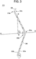
- FIG. 3 is a cross-sectional view of a deflector according to a non-limiting embodiment that may be used in the entrainment-reducing assembly of FIG. 2 .
- the deflector 210 may include a first surface 302a with a first ridge 304a and a second surface 302b with a first furrow 304b.
- the first furrow 304b When installed in the entrainment-reducing assembly 200, the first furrow 304b will face the strainer 216, while the first ridge 304a will face the downcomer 206.
- a first angle ⁇ 1 of the first furrow 304b, as defined by the second surface 302b, should be of a magnitude that is sufficient to cause the uncondensed gas 208 of the impinged two phase jet hitting the deflector 210 to be deflected upward towards the surface of the wetwell liquid 112 to inhibit or prevent the uncondensed gas 208 from entering the strainer 216 and to allow for a separation when the uncondensed gas 208 reaches the headspace of the wetwell 110.
- the first angle ⁇ 1 may range from about 155° to 170°.
- the deflector 210 may optionally have a periphery 308 that slopes away from the suction structure 212 so as to form a second ridge 310a and a second furrow 310b, wherein the periphery 308 enhances the deflection of the uncondensed gas 208 away from the suction structure 212.
- a second angle ⁇ 2 of the second furrow 310b may range from 155° to 180°.
- the second ridge 310a and/or the second furrow 310b may be curved instead of being angular.
- the deflector 210 may also include a plurality of perforations 306 extending from the first surface 302a to the second surface 302b.
- the plurality of perforations 306 allow the liquid 112 to flow through the deflector 210, thereby reducing the differential force across the deflector 210 and allowing the liquid 112 to enter the strainer 216.
- the plurality of perforations 306 may be angled inward toward the suction structure 212 and/or the first furrow 304b so as to allow entry of the liquid 112 while deflecting the uncondensed gas 208 away from the suction structure 212. In FIG.
- the third angle ⁇ 3 may range from about 45° to 135° (e.g., 60° to 90°).
- the diameter of each of the plurality of perforations 306 may be sized to be about two times the average expected bubble size of the uncondensed gas 208 impinging on the deflector 210. As noted above, the plurality of perforations 306 are at a third angle ⁇ 3 that reduces or prevents bubble entrainment as the two phase jet impinges on the first surface 302a.
- the amount of uncondensed gas 208 entrained through the plurality of perforations 306 is a function of perforation diameter, perforation length, and the water flow rate.
- the Froude number (Fr) should be a value that gives the uncondensed gas 208 an adequate opportunity to be deflected and rise toward the headspace of the wetwell 110.
- Fr ⁇ 0.31
- the perforations 306 have been discussed in the context of a circular hole, it should be understood that example embodiments are not limited thereto.
- the perforations 306 may be in the form of other curved shapes or polygonal shapes (e.g., slits)
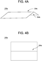
- FIG. 4A is a perspective view of another deflector that may be used in the entrainment-reducing assembly of FIG. 2 .
- FIG. 4B is a plan view of the deflector of FIG. 4A .
- the deflector 210 is in the form of a bent sheet 210a including a first ridge 304a and a first furrow 304b.
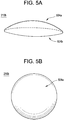
- FIG. 5A is a perspective view of another deflector that may be used in the entrainment-reducing assembly of FIG. 2 .
- FIG. 5B is a plan view of the deflector of FIG. 5A .
- the deflector 210 is in the form of a curved shield 210b including a convex side 504a and a concave side 504b.
- FIG. 6A is a perspective view of another deflector that may be used in the entrainment-reducing assembly of FIG. 2 .
- FIG. 6B is a plan view of the deflector of FIG. 6A .
- the deflector 210 is in the form of a curved-type louvered arrangement 210c including a first curved portion 600a, a second curved portion 600b, and a third curved portion 600c.
- the second curved portion 600b and a third curved portion 600c are provided with an opening in the center thereof such that when arranged with the first curved portion 600a into an overlapping louvered arrangement, the first curved portion 600a and the second curved portion 600b define a first passage 606a therebetween, while the second curved portion 600b and the third curved portion 600c define a second passage 606b therebetween.
- first curved portion 600a and the second curved portion 600b define a first passage 606a therebetween
- the second curved portion 600b and the third curved portion 600c define a second passage 606b therebetween.
- FIG. 7A is a perspective view of another deflector that may be used in the entrainment-reducing assembly of FIG. 2 .
- FIG. 7B is a plan view of the deflector of FIG. 7A .
- the deflector 210 is in the form of a linear-type louvered arrangement 210d including a first slat 700a, a second slat 700b, and a third slat 700c.
- the first slat 700a and the second slat 700b define a first slit 706a therebetween, while the second slat 700b and the third slat 700c define a second slit 706b therebetween.
- first slat 700a and the second slat 700b define a first slit 706a therebetween
- the second slat 700b and the third slat 700c define a second slit 706b therebetween.
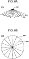
- FIG. 8A is a perspective view of another deflector that may be used in the entrainment-reducing assembly of FIG. 2 .
- FIG. 8B is a plan view of the deflector of FIG. 8A .
- the deflector 210 is in the form of a radially-configured corrugated sheet 210e including a plurality of alternating radially-oriented ridges 804a and radially-oriented furrows 804b that expand outward radially from a point of common convergence 802.
- FIG. 3 it should be understood that one or more of the features discussed in connection with FIG. 3 may be applied to this example.
Landscapes
- Engineering & Computer Science (AREA)
- Physics & Mathematics (AREA)
- Plasma & Fusion (AREA)
- General Engineering & Computer Science (AREA)
- High Energy & Nuclear Physics (AREA)
- Mechanical Engineering (AREA)
- Structure Of Emergency Protection For Nuclear Reactors (AREA)
- Structures Of Non-Positive Displacement Pumps (AREA)
Description
- The present disclosure relates to the reduction or prevention of the entrainment of gases into the suction of a pump during a loss of coolant accident (LOCA).
- During a Loss of Coolant Accident (LOCA), the Emergency Core Cooling System (ECCS) must pump water to maintain the reactor core water level and to provide a cooling function to the reactor core. However, this same transient may cause gases to be forced downward into an operating Emergency Core Cooling System (ECCS) suction strainer, resulting in gas entrainment. In particular, during a Loss of Coolant Accident (LOCA), both condensable gases (e.g., steam) and non-condensable gases (e.g., nitrogen (N2)) may be directed into a suppression pool, thereby elevating the level of the suppression pool. An Emergency Core Cooling System (ECCS) pump may be used to maintain the suppression pool at an acceptable level by suctioning excess liquid from the suppression pool and supplying the excess liquid to the reactor core. However, the non-condensable gases may become entrained along with the liquid into the suction of the Emergency Core Cooling System (ECCS) pump, thereby causing loss of suction and decreased flow to the reactor core. Furthermore, the presence of non-condensable gases within the Emergency Core Cooling System (ECCS) pump causes cavitation and pump damage, which poses additional safety hazards.
-
JP2002 168985 - The present disclosure describes various devices, assemblies, systems, and methods for preventing pumps (e.g., Emergency Core Cooling System (ECCS) pumps) from receiving relatively large quantities of entrained gas in the suction piping, which would cause cavitation and ultimately result in the failure of the pump. The teachings herein also promote the mitigation or prevention of non-condensable gases from reaching the suction strainers within the wetwell. Specially-designed deflector shields or baffles may be arranged between the drywell-to-wetwell vent downcomer and the Emergency Core Cooling System (ECCS) pump suction strainer. By preventing gases from the reaching the Emergency Core Cooling System (ECCS) suction water, the availability of pump operation for the duration of a postulated accident may be increased.
- An entrainment-reducing assembly may include a container configured to hold a liquid. The container may include an upper portion and a lower portion. A venting arrangement may extend into the container. The venting arrangement may be configured to direct gases into the container. A suction structure may extend into the lower portion of the container. The suction structure may be configured to carry out an extraction of the liquid from the container. A deflector may be disposed between the suction structure and the venting arrangement within the container. The deflector may be configured to reduce the entrainment of uncondensed gases during the extraction of the liquid.
- A reactor system may include a first container and a second container. The first container may define a drywell therein. The second container may define a wetwell therein. The second container may include an upper portion and a lower portion. A venting arrangement may connect the drywell to the wetwell. The venting arrangement may include a proximal end extending into the drywell and a distal end extending into the upper portion of the wetwell. A suction structure may extend into the lower portion of the wetwell. A deflector may be disposed between the suction structure and the distal end of the venting arrangement within the second container.
- A method of reducing entrainment may include discharging gases from a venting arrangement into a liquid. The method may additionally include alleviating an elevated level of the liquid resulting from condensing gases by performing an extraction of the liquid with a suction structure. The method may further include shielding the suction structure from the entrainment of uncondensed gases in the liquid with a deflector during the extraction of the liquid.
- The various features and advantages of the non-limiting embodiments herein may become more apparent upon review of the detailed description in conjunction with the accompanying drawings. The accompanying drawings are merely provided for illustrative purposes and should not be interpreted to limit the scope of the claims. The accompanying drawings are not to be considered as drawn to scale unless explicitly noted. For purposes of clarity, various dimensions of the drawings may have been exaggerated.
-
FIG. 1 is a simplified, cross-sectional view of a reactor system. -
FIG. 2 is cross-sectional view of an entrainment-reducing assembly that may be used in the reactor system ofFIG. 1 . -
FIG. 3 is a cross-sectional view of a deflector according to a non-limiting embodiment that may be used in the entrainment-reducing assembly ofFIG. 2 . -
FIG. 4A is a perspective view of another deflector that may be used in the entrainment-reducing assembly ofFIG. 2 . -
FIG. 4B is a plan view of the deflector ofFIG. 4A . -
FIG. 5A is a perspective view of another deflector that may be used in the entrainment-reducing assembly ofFIG. 2 . -
FIG. 5B is a plan view of the deflector ofFIG. 5A . -
FIG. 6A is a perspective view of another deflector that may be used in the entrainment-reducing assembly ofFIG. 2 . -
FIG. 6B is a plan view of the deflector ofFIG. 6A . -
FIG. 7A is a perspective view of another deflector that may be used in the entrainment-reducing assembly ofFIG. 2 . -
FIG. 7B is a plan view of the deflector ofFIG. 7A . -
FIG. 8A is a perspective view of another deflector that may be used in the entramment-reducing assembly ofFIG. 2 . -
FIG. 8B is a plan view of the deflector ofFIG. 8A . - It should be understood that when an element or layer is referred to as being "on," "connected to," "coupled to," or "covering" another element or layer, it may be directly on, connected to, coupled to, or covering the other element or layer or intervening elements or layers may be present. In contrast, when an element is referred to as being "directly on," "directly connected to," or "directly coupled to" another element or layer, there are no intervening elements or layers present. Like numbers refer to like elements throughout the specification. As used herein, the term "and/or" includes any and all combinations of one or more of the associated listed items.
- It should be understood that, although the terms first, second, third, etc. may be used herein to describe various elements, components, regions, layers and/or sections, these elements, components, regions, layers, and/or sections should not be limited by these terms. These terms are only used to distinguish one element, component, region, layer, or section from another region, layer, or section. Thus, a first element, component, region, layer, or section discussed below could be termed a second element, component, region, layer, or section without departing from the teachings of example embodiments.
- Spatially relative terms (e.g., "beneath," "below," "lower," "above," "upper," and the like) may be used herein for ease of description to describe one element or feature's relationship to another element(s) or feature(s) as illustrated in the figures. It should be understood that the spatially relative terms are intended to encompass different orientations of the device in use or operation in addition to the orientation depicted in the figures. For example, if the device in the figures is turned over, elements described as "below" or "beneath" other elements or features would then be oriented "above" the other elements or features. Thus, the term "below" may encompass both an orientation of above and below. The device may be otherwise oriented (rotated 90 degrees or at other orientations) and the spatially relative descriptors used herein interpreted accordingly.
- The terminology used herein is for the purpose of describing various embodiments only and is not intended to be limiting of example embodiments. As used herein, the singular forms "a," "an," and "the" are intended to include the plural forms as well, unless the context clearly indicates otherwise. It will be further understood that the terms "includes," "including," "comprises," and/or "comprising," when used in this specification, specify the presence of stated features, integers, steps, operations, elements, and/or components, but do not preclude the presence or addition of one or more other features, integers, steps, operations, elements, components, and/or groups thereof.
- Example embodiments are described herein with reference to cross-sectional illustrations that are schematic illustrations of idealized embodiments (and intermediate structures) of example embodiments. As such, variations from the shapes of the illustrations as a result, for example, of manufacturing techniques and/or tolerances, are to be expected. Thus, example embodiments should not be construed as limited to the shapes of regions illustrated herein but are to include deviations in shapes that result, for example, from manufacturing. For example, an implanted region illustrated as a rectangle will, typically, have rounded or curved features and/or a gradient of implant concentration at its edges rather than a binary change from implanted to non-implanted region. Likewise, a buried region formed by implantation may result in some implantation in the region between the buried region and the surface through which the implantation takes place. Thus, the regions illustrated in the figures are schematic in nature and their shapes are not intended to illustrate the actual shape of a region of a device and are not intended to limit the scope of example embodiments.
- Unless otherwise defined, all terms (including technical and scientific terms) used herein have the same meaning as commonly understood by one of ordinary skill in the art to which example embodiments belong. It will be further understood that terms, including those defined in commonly used dictionaries, should be interpreted as having a meaning that is consistent with their meaning in the context of the relevant art and will not be interpreted in an idealized or overly formal sense unless expressly so defined herein.
- Various embodiments of the present disclosure relate to devices and assemblies, which when used inside a nuclear reactor (e.g., Boiling Water Reactor (BWR) Mark I or Mark II wetwells (torus)), will mitigate or solve the issue of "loss of suction" to Emergency Core Cooling System (ECCS) pumps due to the entrainment of steam and/or non-condensable gases during a Loss of Coolant Accident (LOCA) in the drywell. Various embodiments of the present disclosure also relate to systems and methods for reducing the entrainment of gases.
- Although the description herein is in the context of a Boiling Water Reactor (BWR), it should be understood that example embodiments are not limited thereto. In addition to the various types of Boiling Water Reactors (BWR), the present disclosure may also be applied to Pressurized Water Reactor (PWR) emergency water sumps with suction strainers. Furthermore, the teachings herein may be applied to non-reactor settings. For instance, the devices, assemblies, systems, and methods may be used in other situations in which a suction is taken from a large reservoir of liquid (e.g., water), whereupon a large injection of non-condensable gases could result in these gases being entrained or swept into the suction pipe, thereby causing the downstream pump to fail.
-
FIG. 1 is a simplified, cross-sectional view of a reactor system. Referring toFIG. 1 , areactor system 100 includes afirst container 102 defining a drywell 104 and asecond container 108 defining awetwell 110. Areactor pressure vessel 106 is situated within the drywell 104. A body of liquid 112 (e.g., suppression pool) is disposed within thewetwell 110. The drywell 104 is connected to thewetwell 110 via aventing arrangement 114. The details ofFIG. 1 are discussed in connection with the subsequent drawings. - The present disclosure details the mitigation or prevention of gases from being entrained in the suction of Emergency Core Cooling System (ECCS) pumps. Such mitigation or prevention may improve the safety operation and availability of the Emergency Core Cooling System (ECCS) pumps during a Loss of Coolant Accident (LOCA). In particular, a relatively large Loss of Coolant Accident (LOCA) may force gas into the Emergency Core Cooling System (ECCS) piping. A relatively large gas entrainment may lead to gas entering an Emergency Core Cooling System (ECCS) pump, resulting in pump damage from cavitation and reduced flow (if any flow at all) to the reactor core. Consequently, the ability of the Emergency Core Cooling System (ECCS) pumps to maintain the proper water level in the reactor core may be affected. That being said, the present disclosure is directed to mitigating or preventing the possibility of gas reaching the suction of the Emergency Core Cooling System (ECCS) piping.
- A centrifugal pump is used in the Emergency Core Cooling Systems (ECCS) of Boiling Water Reactors (BWR) and Pressurized Water Reactors (PWR). A centrifugal pump requires a net positive suction head (NPSH) at a given location relative to a reference point as defined by the following equation:

- If a centrifugal pump does not have a sufficient net positive suction head (NPSH), then low or no flow, pump wear, and in the worst case, seizing of the pump will result. During a Loss of Coolant Accident (LOCA), as will be explained, gases (e.g., non-condensable nitrogen, which was previously used to inert the drywell, and steam, resulting from the flashing flow from a design basis line break) can be forced through the suction strainer in the wetwell (e.g., torus-shaped wetwell) and then into the Emergency Core Cooling System (ECCS) suction header and finally into the pump.
- Depending on the anticipated Emergency Core Cooling System (ECCS) configuration and potential active failures, the ranges of flow1 in an Emergency Core Cooling System (ECCS) header range from 600 to 30,000 gal/min (5,010 to 417,000 lbs/min; 1 gal=3.79 litres, 1 lb = 454 grams). With a ring header diameter of 2 feet (1 foot = 30.5 cms), this results in a Reynolds number ranging from 105 to 107. Reynolds
1 Assuming RCIC ∼600 gpm, HPCS (BWR/5s and 6s) ∼ 7,175 gpm, Low pressure systems that take SP suction: LPCI -4 pumps * 8400 gpm/pump = 33,600 gpm, LPCS ∼ 2 pumps * 8400 gpm/pump = 16,800 gpm. number2* is the ratio of inertial forces within a fluid to its vicious forces and is defined by the following equation:
2 Assuming Viscosity at 100°F (100°F = 37.8°C)
Kinematic viscosity = 4.579E = 4.579E-4 lbm/ft/s; Density at 100°F = 8.34 lbm/gallon;
-4 / 8.34 * 60 = 0.003294 gal/ft/min; D = 2 ft; D/A = D/(1/4 pi D2) = 4/ (pi D) = 0.6366 1/ft; Re = Q [gal/min] * 193.2 min/gal. - Due to the relatively high Reynolds number, the flow regime is highly turbulent and the inertial force dominates over buoyant forces of gas entrained in the water. Therefore, to remove entrained gases from the water the Reynolds number needs to reach a value below 1000, so that buoyancy of the entrained gas can allow phase separation. Even at a Reynolds number of about 100, a wobble occurs that causes bubbles to rise in a spiral or helical path. This velocity of the fluid can occur with expansion of the flow area and is enhanced with flow direction changes. These entrained air bubbles in the pool will take much longer to rise to the surface because of the viscosity of the water. Air bubbles will rise and achieve a terminal velocity governed by Stoke's law.
-
FIG. 2 is cross-sectional view of an entrainment-reducing assembly that may be used in the reactor system ofFIG. 1 . Although the entrainment-reducing assembly ofFIG. 2 is shown in connection with a Boiling Water Reactor (BWR) Mark I suppression pool, it should be understood that example set-ups are not limited thereto. Referring toFIG. 2 , the entrainment-reducingassembly 200 includes thesecond container 108, which defines thewetwell 110 and holds the body of liquid 112 (e.g., suppression pool of water) therein. The ventingarrangement 114 connects the drywell 104 (FIG. 1 ) to thewetwell 110. The ventingarrangement 114 includes avent pipe 202, aheader 204, and a plurality ofdowncomers 206. Asuction structure 212 protrudes into thesecond container 108 at a position below the surface of the liquid 112. Thesuction structure 212 includes asuction pipe 214 and astrainer 216 secured to thesuction pipe 214. Thestrainer 216 may have a variety of configurations and shapes and is designed to allow the liquid 112 to enter with relative ease while filtering out relatively large-sized debris. - A
deflector 210 is arranged between thesuction structure 212 and theventing arrangement 114 to deflectuncondensed gas 208 away from thesuction structure 212 so as to reduce or prevent the entrainment of theuncondensed gas 208 with the liquid 112. A spacing distance between thedeflector 210 and thesuction structure 212 may be equal to or less than half of a total distance between the ventingarrangement 114 and thesuction structure 212. Thedeflector 210 may be secured to thesecond container 108 such that thedeflector 210 does not directly contact thesuction structure 212. After passing through thestrainer 216 and entering thesuction pipe 214, the liquid 112 is directed through the suction line to a pump. Optionally, a gas/liquid separator may be additionally connected to the suction line to separate out any uncondensed gases that may have been entrained with the liquid 112. The gases may be separated based on density, and the separated gases may be redirected back into thewetwell 110. - The common term for a Mark I wetwell is a torus, since the
second container 108 defining thewetwell 110 may be in the form of a torus. When thesecond container 108 is in a form of a torus, eightvent pipes 202 may connect the drywell 104 to thewetwell 110. In such an example, theheader 204 may be in form of a ring within the torus that connects thevent pipes 202. In addition to thevent pipes 202, the gas flow from the drywell 104 is further divided by a plurality ofdowncomers 206 which discharge the gas below the surface of the liquid 112 (e.g., subcooled water). Steam quenchers may be optionally attached to thedowncomers 206. Thestrainer 216 is positioned so as to remain submerged near the bottom of thesecond container 108. The liquid 112 is removed from thewetwell 110 via thesuction structure 212 and is conveyed through thesuction pipe 214 to the Emergency Core Cooling System (ECCS) pumps. Thedeflector 210 is positioned between thestrainer 216 and thedowncomer 206 to reduce or prevent the entrainment of anuncondensed gas 208 into the suction line. Although not shown in the drawings, it should be understood that asuction structure 212 and/or adeflector 210 may be provided for eachdowncomer 206. - The entrainment-reducing
assembly 200 will be described in additional detail with regard the following three states: normal operations "Steady State," a state after a "Large LOCA" in the drywell, and the resulting system transient "Gas to ECCS Pumps" state. - A "Steady State" assumes that the reactor is at normal operating temperature and pressure and assumed at 100% power. In such a state, the liquid 112 in the
wetwell 110 is at a normal level. - During a "Large LOCA" state, there is a break at rated power, which involves an instantaneous rupture of a steam or recirculation line in the
dry well 104. As a result of the rupture, a shock wave exits with a wave amplitude approaching the reactor operating pressure (e.g., 1000 psig). The attenuated wave enters the ventingarrangement 114 and progresses into thewetwell 110. The high pressure gases (e.g., N2 and steam) from the drywell 104 are forced downward through the ventingarrangement 114. The high pressure gases exit thedowncomer 206 and set off several phenomena, such as pool swell in the torus increasing from the steady state (normal) level to an elevated level, condensation oscillation as the steam chaotically condenses and pool water voids, and forcible downward direction of the gas mixture. - In a conventional system, if the Emergency Core Cooling System (ECCS) suction strainer is located in the vicinity of the downcomer nozzle, the gas jet can be forced into the suction strainer, thereby introducing a slug of gas into the Emergency Core Cooling System (ECCS) header. If the Emergency Core Cooling System (ECCS) pumps have already been activated, with water flow from the wetwell established, this slug of gas can move into the Emergency Core Cooling System (ECCS) pump, resulting in reduced pump flow, cavitation, and/or pump damage.
- In contrast, in the present disclosure, a
deflector 210 is in place as the gas jet is forced towards thestrainer 216. As a result, thedeflector 210 deflects the gas flow, thereby allowing for buoyancy effects to permit the gas to separate and rise to the headspace of thewetwell 110. Thestrainer 216 under thedeflector 210 still maintains suction of the liquid 112 from thewetwell 110. Additionally, as schematically shown inFIG. 2 , gas/liquid separator may be used to remove gas that may have become entrained with the liquid 112 into the Emergency Core Cooling System (ECCS) suction line. The gas that is removed from the suction line may be put back into the headspace of thewetwell 110. -
FIG. 3 is a cross-sectional view of a deflector according to a non-limiting embodiment that may be used in the entrainment-reducing assembly ofFIG. 2 . Referring toFIG. 3 , thedeflector 210 may include afirst surface 302a with afirst ridge 304a and asecond surface 302b with afirst furrow 304b. When installed in the entrainment-reducingassembly 200, thefirst furrow 304b will face thestrainer 216, while thefirst ridge 304a will face thedowncomer 206. A first angle α1 of thefirst furrow 304b, as defined by thesecond surface 302b, should be of a magnitude that is sufficient to cause theuncondensed gas 208 of the impinged two phase jet hitting thedeflector 210 to be deflected upward towards the surface of the wetwell liquid 112 to inhibit or prevent theuncondensed gas 208 from entering thestrainer 216 and to allow for a separation when theuncondensed gas 208 reaches the headspace of thewetwell 110. In a non-limiting embodiment, the first angle α1 may range from about 155° to 170°. - The
deflector 210 may optionally have aperiphery 308 that slopes away from thesuction structure 212 so as to form asecond ridge 310a and asecond furrow 310b, wherein theperiphery 308 enhances the deflection of theuncondensed gas 208 away from thesuction structure 212. A second angle α2 of thesecond furrow 310b may range from 155° to 180°. Although not shown, it should be understood that thesecond ridge 310a and/or thesecond furrow 310b may be curved instead of being angular. - The
deflector 210 may also include a plurality ofperforations 306 extending from thefirst surface 302a to thesecond surface 302b. The plurality ofperforations 306 allow the liquid 112 to flow through thedeflector 210, thereby reducing the differential force across thedeflector 210 and allowing the liquid 112 to enter thestrainer 216. The plurality ofperforations 306 may be angled inward toward thesuction structure 212 and/or thefirst furrow 304b so as to allow entry of the liquid 112 while deflecting theuncondensed gas 208 away from thesuction structure 212. InFIG. 3 , assuming that A-A is a center line that bisects thedeflector 210 and B-B is a line that corresponds to a longitudinal axis of theperforation 306 and intersects A-A to form a third angle α3, the third angle α3 may range from about 45° to 135° (e.g., 60° to 90°). - The diameter of each of the plurality of
perforations 306 may be sized to be about two times the average expected bubble size of theuncondensed gas 208 impinging on thedeflector 210. As noted above, the plurality ofperforations 306 are at a third angle α3 that reduces or prevents bubble entrainment as the two phase jet impinges on thefirst surface 302a. The amount ofuncondensed gas 208 entrained through the plurality ofperforations 306 is a function of perforation diameter, perforation length, and the water flow rate. A method to optimize the diameter of theperforations 306 use the Froude number (Fr):
- The Froude number (Fr) should be a value that gives the
uncondensed gas 208 an adequate opportunity to be deflected and rise toward the headspace of thewetwell 110. In a non-limiting embodiment, Fr < 0.31 Although theperforations 306 have been discussed in the context of a circular hole, it should be understood that example embodiments are not limited thereto. For instance, theperforations 306 may be in the form of other curved shapes or polygonal shapes (e.g., slits) -
FIG. 4A is a perspective view of another deflector that may be used in the entrainment-reducing assembly ofFIG. 2 .FIG. 4B is a plan view of the deflector ofFIG. 4A . Referring toFIGS. 4A-4B , thedeflector 210 is in the form of abent sheet 210a including afirst ridge 304a and afirst furrow 304b. Although not shown, it should be understood that one or more of the features discussed in connection withFIG. 3 may be applied to this example. -
FIG. 5A is a perspective view of another deflector that may be used in the entrainment-reducing assembly ofFIG. 2 .FIG. 5B is a plan view of the deflector ofFIG. 5A . Referring toFIGS. 5A-5B , thedeflector 210 is in the form of acurved shield 210b including aconvex side 504a and aconcave side 504b. Although not shown, it should be understood that one or more of the features discussed in connection withFIG. 3 may be applied to this example. -
FIG. 6A is a perspective view of another deflector that may be used in the entrainment-reducing assembly ofFIG. 2 .FIG. 6B is a plan view of the deflector ofFIG. 6A . Referring toFIGS. 6A-6B , thedeflector 210 is in the form of a curved-typelouvered arrangement 210c including a firstcurved portion 600a, a secondcurved portion 600b, and a thirdcurved portion 600c. The secondcurved portion 600b and a thirdcurved portion 600c are provided with an opening in the center thereof such that when arranged with the firstcurved portion 600a into an overlapping louvered arrangement, the firstcurved portion 600a and the secondcurved portion 600b define afirst passage 606a therebetween, while the secondcurved portion 600b and the thirdcurved portion 600c define asecond passage 606b therebetween. Although not shown, it should be understood that one or more of the features discussed in connection withFIG. 3 may be applied to this example. -
FIG. 7A is a perspective view of another deflector that may be used in the entrainment-reducing assembly ofFIG. 2 .FIG. 7B is a plan view of the deflector ofFIG. 7A . Referring toFIGS. 7A-7B , thedeflector 210 is in the form of a linear-type louvered arrangement 210d including afirst slat 700a, asecond slat 700b, and athird slat 700c. When arranged in an overlapping louvered arrangement, thefirst slat 700a and thesecond slat 700b define afirst slit 706a therebetween, while thesecond slat 700b and thethird slat 700c define asecond slit 706b therebetween. Although not shown, it should be understood that one or more of the features discussed in connection withFIG. 3 may be applied to this example. -
FIG. 8A is a perspective view of another deflector that may be used in the entrainment-reducing assembly ofFIG. 2 .FIG. 8B is a plan view of the deflector ofFIG. 8A . Referring toFIGS. 8A-8B , thedeflector 210 is in the form of a radially-configuredcorrugated sheet 210e including a plurality of alternating radially-orientedridges 804a and radially-orientedfurrows 804b that expand outward radially from a point ofcommon convergence 802. Although not shown, it should be understood that one or more of the features discussed in connection withFIG. 3 may be applied to this example. - While a number of example embodiments have been disclosed herein, it should be understood that other variations may be possible. Such variations are not to be regarded as a departure from the scope of the present disclosure, and all such modifications as would be obvious to one skilled in the art are intended to be included within the scope of the following claims.
Claims (13)
- An entrainment-reducing assembly (200), comprising:a container (108) configured to hold a liquid (112), the container including an upper portion and a lower portion;a venting arrangement (114) extending into the container (108), the venting arrangement configured to direct gases into the container;a suction structure (212) extending into the lower portion of the container, the suction structure configured to carry out an extraction of the liquid from the container; anda deflector (210) disposed between the suction structure (212) and the venting arrangement (114) within the container, characterized in that the deflector has perforations extending therethrough and configured to allow entry of the liquid while deflecting uncondensed gases (208) away from the suction structure to reduce the entrainment of uncondensed gases (208) during the extraction of the liquid, the deflector having a center line and a through-hole line, the center line bisecting the deflector, the through-hole line corresponding to a longitudinal axis of at least one of the perforations, the center line and the through-hole line intersecting to define an angle therebetween, the angle ranging from 45° to 135°.
- The entrainment-reducing assembly (200) of claim 1, wherein the venting arrangement (114) extends into the upper portion of the container (108).
- The entrainment-reducing assembly (200) of claim 1, wherein the suction structure (212) includes a suction pipe (214) and a strainer (216) secured to the suction pipe within the container, the deflector (210) disposed between the strainer and the venting arrangement (114).
- The entrainment-reducing assembly (200) of claim 1, wherein a spacing distance between the deflector (210) and the suction structure (212) is equal to or less than half of a total distance between the venting arrangement (114) and the suction structure (212).
- The entrainment-reducing (200) assembly of claim 3, wherein the deflector (210) is secured to the container (108) such that the deflector does not directly contact the strainer (216).
- The entrainment-reducing assembly (200) of claim 1, wherein the deflector (210) flares away from the venting arrangement (114) and toward the suction structure (212) with increasing distance from the venting arrangement.
- The entrainment-reducing assembly (200) of claim 1, wherein the deflector (210) is in a form of a bent sheet, the bent sheet including a furrow that faces the suction structure (212).
- The entrainment-reducing assembly (200) of claim 7, wherein the furrow is defined by two opposing sloping surfaces, an angle between the two opposing sloping surfaces being between about 155° to 170°.
- The entrainment-reducing assembly (200) of claim 1, wherein the deflector (210) is in a form of a corrugated sheet, the corrugated sheet including a plurality of alternating ridges and furrows that expand outward radially from a point of common convergence toward the suction structure.
- The entrainment-reducing assembly (200) of claim 1, wherein the deflector (210) is in a form of a curved shield, the curved shield including a concave side that faces the suction structure.
- The entrainment-reducing assembly (200) of claim 1, wherein the deflector (210) has a louvered arrangement, the louvered arrangement including a plurality of overlapping slats defining a plurality of slits therebetween.
- A method of reducing entrainment, comprising:discharging gases from a venting arrangement (114) into a liquid;alleviating an elevated level of the liquid resulting from condensing gases by performing an extraction of the liquid with a suction structure (212); andshielding the suction structure from the entrainment of uncondensed gases in the liquid with a deflector (210) during the extraction of the liquid; whereinthe deflector (210) is disposed between the suction structure (212) and the venting arrangement (114) within the container, and characterized in that the deflector has perforations extending therethrough and configured to allow entry of the liquid while deflecting uncondensed gases (208) away from the suction structure to reduce the entrainment of uncondensed gases (208) during the extraction of the liquid, the deflector having a center line and a through-hole line, the center line bisecting the deflector, the through-hole line corresponding to a longitudinal axis of at least one of the perforations, the center line and the through-hole line intersecting to define an angle therebetween, the angle ranging from 45° to 135°.
- The method of claim 12, wherein the shielding includes providing a plurality of perforations that extend through the deflector (210) at an angle toward the suction structure (212) such that a Froude number (Fr) is less than 0.31 to allow a flow of the liquid through the plurality of perforations while hindering a passage of the uncondensed gases through the plurality of perforations,

Applications Claiming Priority (2)
| Application Number | Priority Date | Filing Date | Title |
|---|---|---|---|
| US13/721,346 US9738440B2 (en) | 2012-12-20 | 2012-12-20 | Entrainment-reducing assembly, system including the assembly, and method of reducing entrainment of gases with the assembly |
| PCT/US2013/075051 WO2014099668A1 (en) | 2012-12-20 | 2013-12-13 | Entrainment-reducing assembly, system including the assembly, and method of reducing entrainment of gases with the assembly |
Publications (2)
| Publication Number | Publication Date |
|---|---|
| EP2936498A1 EP2936498A1 (en) | 2015-10-28 |
| EP2936498B1 true EP2936498B1 (en) | 2017-10-11 |
Family
ID=49887337
Family Applications (1)
| Application Number | Title | Priority Date | Filing Date |
|---|---|---|---|
| EP13815335.8A Active EP2936498B1 (en) | 2012-12-20 | 2013-12-13 | Entrainment-reducing assembly, system including the assembly, and method of reducing entrainment of gases with the assembly |
Country Status (5)
| Country | Link |
|---|---|
| US (2) | US9738440B2 (en) |
| EP (1) | EP2936498B1 (en) |
| JP (1) | JP6514643B2 (en) |
| ES (1) | ES2646225T3 (en) |
| WO (1) | WO2014099668A1 (en) |
Families Citing this family (3)
| Publication number | Priority date | Publication date | Assignee | Title |
|---|---|---|---|---|
| CN103687656B (en) * | 2011-06-01 | 2016-03-02 | 特兰斯科产品股份有限公司 | Large-capacity suction filters for emergency core cooling systems in nuclear power plants |
| US10755824B2 (en) | 2016-09-20 | 2020-08-25 | Continuum Dynamics, Inc. | Nuclear reactor using controlled debris to mitigate ECCS strainer pressure head loss |
| CN114171217B (en) * | 2021-10-29 | 2024-12-17 | 中广核研究院有限公司 | Pressure-suppressing pool device and nuclear reactor |
Family Cites Families (44)
| Publication number | Priority date | Publication date | Assignee | Title |
|---|---|---|---|---|
| GB705548A (en) | 1951-07-19 | 1954-03-17 | Celanese Corp | An apparatus for carrying out reactions between liquids and gases |
| US2917926A (en) * | 1957-10-28 | 1959-12-22 | Burton K Jaquith | Means for extracting true proportionate samples of fluid material |
| FR1207124A (en) * | 1958-08-14 | 1960-02-15 | Commissariat Energie Atomique | Barrage cylinder for controlling the evacuation of water and the suppression of the driving height of natural circulation in a boiling water atomic reactor |
| FR1364645A (en) * | 1963-04-05 | 1964-06-26 | Grenobloise Etude Appl | Improvements to nuclear reactors of the swimming pool type |
| US4050983A (en) * | 1970-08-05 | 1977-09-27 | Nucledyne Engineering Corporation | Passive containment system |
| US4210614A (en) * | 1970-08-05 | 1980-07-01 | Nucledyne Engineering Corp. | Passive containment system |
| DE2346726C3 (en) * | 1973-09-17 | 1979-03-01 | Siemens Ag, 1000 Berlin Und 8000 Muenchen | Nuclear reactor installation and method for its ventilation |
| JPS52108573A (en) * | 1976-03-09 | 1977-09-12 | Toyobo Co Ltd | Consecutive bubble removing device |
| JPS5445895U (en) * | 1977-09-07 | 1979-03-29 | ||
| JPH0810264B2 (en) * | 1986-03-19 | 1996-01-31 | 株式会社日立製作所 | Emergency core cooling system |
| US5011652A (en) * | 1986-09-19 | 1991-04-30 | Hitachi, Ltd. | Nuclear power facilities |
| JPS63229390A (en) * | 1987-03-18 | 1988-09-26 | 株式会社日立製作所 | Reactor |
| JPH0762717B2 (en) * | 1988-09-21 | 1995-07-05 | 株式会社日立製作所 | Liquid injection device for high temperature and high pressure vessels |
| US5217680A (en) * | 1988-09-21 | 1993-06-08 | Hitachi, Ltd. | Liquid filling method for a high-temperature and high-pressure vessel and apparatus therefor |
| JPH0792515B2 (en) * | 1988-11-16 | 1995-10-09 | 株式会社日立製作所 | Containment vessel |
| US5106571A (en) * | 1989-03-20 | 1992-04-21 | Wade Gentry E | Containment heat removal system |
| JP2528977B2 (en) * | 1989-11-22 | 1996-08-28 | 株式会社日立製作所 | Containment vessel |
| JP2971614B2 (en) * | 1991-05-22 | 1999-11-08 | 株式会社日立製作所 | Reactor containment vessel decompression device |
| US5282230A (en) * | 1992-11-25 | 1994-01-25 | General Electric Company | Passive containment cooling system |
| US5301215A (en) * | 1992-11-25 | 1994-04-05 | General Electric Company | Nuclear reactor building |
| JP3149606B2 (en) * | 1993-03-11 | 2001-03-26 | 株式会社日立製作所 | Reactor containment cooling system |
| US5345482A (en) * | 1993-05-06 | 1994-09-06 | Westinghouse Electric Corporation | Passive containment cooling water distribution device |
| US5479461A (en) * | 1994-06-30 | 1995-12-26 | Siemens Power Corporation | Attachable debris filter for BWR nuclear fuel assemblies |
| AUPM714794A0 (en) * | 1994-07-29 | 1994-08-18 | International Fluid Separation Pty Limited | Separation apparatus and method |
| CA2136374C (en) * | 1994-11-22 | 2000-05-30 | Ronald Riopel | Method of securing corrugated baffles to an interior of a tank |
| KR100204188B1 (en) * | 1995-08-08 | 1999-06-15 | 김세종 | Method and device for cooling the outer wall of nuclear reactor power plant under heavy accident |
| JP2937986B1 (en) * | 1998-02-09 | 1999-08-23 | 株式会社東芝 | Maintenance method at nuclear power plant |
| JP2002156485A (en) * | 2000-11-15 | 2002-05-31 | Hitachi Ltd | Reactor |
| JP2002168985A (en) | 2000-12-05 | 2002-06-14 | Toshiba Corp | Reactor containment vessel |
| WO2004105047A2 (en) * | 2003-05-15 | 2004-12-02 | Continuum Dynamics, Inc. | Improved self-cleaning strainer |
| US7788867B2 (en) * | 2004-10-13 | 2010-09-07 | General Electric Company | Floor tile debris interceptor and transition plenum in a nuclear power plant |
| JP4987681B2 (en) * | 2007-12-12 | 2012-07-25 | 株式会社東芝 | Primary containment vessel and leak detection floor |
| US8437446B2 (en) * | 2008-11-17 | 2013-05-07 | Nuscale Power, Llc | Steam generator flow by-pass system |
| JP2010203858A (en) * | 2009-03-02 | 2010-09-16 | Toshiba Corp | Reactor container cooling equipment, reactor container, and reactor container cooling method |
| JP2010271147A (en) * | 2009-05-20 | 2010-12-02 | Mitsubishi Heavy Ind Ltd | Nuclear reactor containment structure |
| US20110174159A1 (en) * | 2010-01-15 | 2011-07-21 | Westinghouse Electric Company Llc | Pump suction gas separator |
| JP5787573B2 (en) * | 2011-03-30 | 2015-09-30 | 三菱重工業株式会社 | Gas-liquid separator |
| JP2012230079A (en) * | 2011-04-27 | 2012-11-22 | Hitachi-Ge Nuclear Energy Ltd | Nuclear power plant, fuel pool water cooling apparatus, and fuel pool water cooling method |
| JP2013007574A (en) * | 2011-06-22 | 2013-01-10 | Toshiba Corp | Nuclear power plant |
| US20130287161A1 (en) * | 2012-04-26 | 2013-10-31 | Ge-Hitachi Nuclear Energy Americas Llc | Heat removal system and method for a nuclear reactor |
| JP5911762B2 (en) * | 2012-06-29 | 2016-04-27 | 株式会社東芝 | Nuclear plant and static containment cooling system |
| US20140072090A1 (en) * | 2012-09-13 | 2014-03-13 | Ge-Hitachi Nuclear Energy Americas Llc | Method and system for an alternate rpv energy removal path |
| JP5916584B2 (en) * | 2012-10-24 | 2016-05-11 | 日立Geニュークリア・エナジー株式会社 | Static decay heat removal system and nuclear power plant equipment |
| US10062462B2 (en) * | 2013-08-28 | 2018-08-28 | Korea Atomic Energy Research Institute | Facility for reducing radioactive material and nuclear power plant having the same |
-
2012
- 2012-12-20 US US13/721,346 patent/US9738440B2/en active Active
-
2013
- 2013-12-13 JP JP2015549515A patent/JP6514643B2/en active Active
- 2013-12-13 WO PCT/US2013/075051 patent/WO2014099668A1/en not_active Ceased
- 2013-12-13 ES ES13815335.8T patent/ES2646225T3/en active Active
- 2013-12-13 EP EP13815335.8A patent/EP2936498B1/en active Active
-
2017
- 2017-08-21 US US15/681,856 patent/US10464744B2/en active Active
Non-Patent Citations (1)
| Title |
|---|
| None * |
Also Published As
| Publication number | Publication date |
|---|---|
| WO2014099668A1 (en) | 2014-06-26 |
| US20170369239A1 (en) | 2017-12-28 |
| JP2016507690A (en) | 2016-03-10 |
| US20140175106A1 (en) | 2014-06-26 |
| EP2936498A1 (en) | 2015-10-28 |
| JP6514643B2 (en) | 2019-05-15 |
| US9738440B2 (en) | 2017-08-22 |
| ES2646225T3 (en) | 2017-12-12 |
| US10464744B2 (en) | 2019-11-05 |
Similar Documents
| Publication | Publication Date | Title |
|---|---|---|
| US10464744B2 (en) | Entrainment-reducing assembly, system including the assembly, and method of reducing entrainment of gases with the assembly | |
| US8741014B2 (en) | Multi-stage steam-water separation device and steam-water separator | |
| CN103566683B (en) | Split self-suction type Venturi tube washer | |
| CN101779254B (en) | atomic reactor | |
| EP0018840B1 (en) | Separator for removing entrained moisture from saturated steam in a nuclear steam generator | |
| EP2133884A1 (en) | Emergency core cooling system having core barrel injection extension ducts | |
| EP0495304A1 (en) | Low pressure drop gas-liquid separator | |
| DE3525986C2 (en) | ||
| CN208271566U (en) | Steam pressurizer | |
| JP2915682B2 (en) | Accumulation water injection tank for reactor emergency water injection device | |
| IE46666B1 (en) | A recirculating drainage channel for collecting fluid for recirculation | |
| CN110544543A (en) | safety water protection device and reactor with same | |
| EP2937867B1 (en) | Containment filtered venting system used for nuclear power plant | |
| EP3853473B1 (en) | Wind turbine having a circular and a conical tower structure with passive flow control means and use of such a wind turbine | |
| JP5911126B2 (en) | Quench tank and liquid metal loop | |
| JP5663324B2 (en) | Steam separator and boiling water reactor using the same | |
| JP2001183489A (en) | Steam separator and boiling water reactor | |
| CN116981882A (en) | Water and steam separator for boiler drum | |
| DE29907940U1 (en) | Wind turbine with vertical rotor | |
| WO2012076018A1 (en) | Run-up deflector for an off-shore wind turbine | |
| RU2737657C1 (en) | Separation element | |
| CN116538370B (en) | overflow pipe | |
| CN220176173U (en) | High water level water discharge protection device for deaerator | |
| DE102023101749B4 (en) | Mobile fuel cell system | |
| EP2369171B1 (en) | Hydraulic power station |
Legal Events
| Date | Code | Title | Description |
|---|---|---|---|
| PUAI | Public reference made under article 153(3) epc to a published international application that has entered the european phase |
Free format text: ORIGINAL CODE: 0009012 |
|
| 17P | Request for examination filed |
Effective date: 20150720 |
|
| AK | Designated contracting states |
Kind code of ref document: A1 Designated state(s): AL AT BE BG CH CY CZ DE DK EE ES FI FR GB GR HR HU IE IS IT LI LT LU LV MC MK MT NL NO PL PT RO RS SE SI SK SM TR |
|
| AX | Request for extension of the european patent |
Extension state: BA ME |
|
| DAX | Request for extension of the european patent (deleted) | ||
| 17Q | First examination report despatched |
Effective date: 20160728 |
|
| REG | Reference to a national code |
Ref country code: DE Ref legal event code: R079 Ref document number: 602013027896 Country of ref document: DE Free format text: PREVIOUS MAIN CLASS: G21C0009012000 Ipc: B01D0029010000 |
|
| GRAP | Despatch of communication of intention to grant a patent |
Free format text: ORIGINAL CODE: EPIDOSNIGR1 |
|
| RIC1 | Information provided on ipc code assigned before grant |
Ipc: G21C 9/012 20060101ALI20170601BHEP Ipc: G21C 15/18 20060101ALI20170601BHEP Ipc: B65D 90/22 20060101ALI20170601BHEP Ipc: B01D 29/01 20060101AFI20170601BHEP |
|
| INTG | Intention to grant announced |
Effective date: 20170616 |
|
| GRAS | Grant fee paid |
Free format text: ORIGINAL CODE: EPIDOSNIGR3 |
|
| GRAA | (expected) grant |
Free format text: ORIGINAL CODE: 0009210 |
|
| AK | Designated contracting states |
Kind code of ref document: B1 Designated state(s): AL AT BE BG CH CY CZ DE DK EE ES FI FR GB GR HR HU IE IS IT LI LT LU LV MC MK MT NL NO PL PT RO RS SE SI SK SM TR |
|
| REG | Reference to a national code |
Ref country code: GB Ref legal event code: FG4D |
|
| REG | Reference to a national code |
Ref country code: CH Ref legal event code: EP |
|
| REG | Reference to a national code |
Ref country code: IE Ref legal event code: FG4D |
|
| REG | Reference to a national code |
Ref country code: AT Ref legal event code: REF Ref document number: 935533 Country of ref document: AT Kind code of ref document: T Effective date: 20171115 |
|
| REG | Reference to a national code |
Ref country code: DE Ref legal event code: R096 Ref document number: 602013027896 Country of ref document: DE |
|
| REG | Reference to a national code |
Ref country code: SE Ref legal event code: TRGR |
|
| REG | Reference to a national code |
Ref country code: ES Ref legal event code: FG2A Ref document number: 2646225 Country of ref document: ES Kind code of ref document: T3 Effective date: 20171212 |
|
| REG | Reference to a national code |
Ref country code: NL Ref legal event code: MP Effective date: 20171011 |
|
| REG | Reference to a national code |
Ref country code: LT Ref legal event code: MG4D |
|
| REG | Reference to a national code |
Ref country code: AT Ref legal event code: MK05 Ref document number: 935533 Country of ref document: AT Kind code of ref document: T Effective date: 20171011 |
|
| PG25 | Lapsed in a contracting state [announced via postgrant information from national office to epo] |
Ref country code: NL Free format text: LAPSE BECAUSE OF FAILURE TO SUBMIT A TRANSLATION OF THE DESCRIPTION OR TO PAY THE FEE WITHIN THE PRESCRIBED TIME-LIMIT Effective date: 20171011 |
|
| PG25 | Lapsed in a contracting state [announced via postgrant information from national office to epo] |
Ref country code: NO Free format text: LAPSE BECAUSE OF FAILURE TO SUBMIT A TRANSLATION OF THE DESCRIPTION OR TO PAY THE FEE WITHIN THE PRESCRIBED TIME-LIMIT Effective date: 20180111 Ref country code: LT Free format text: LAPSE BECAUSE OF FAILURE TO SUBMIT A TRANSLATION OF THE DESCRIPTION OR TO PAY THE FEE WITHIN THE PRESCRIBED TIME-LIMIT Effective date: 20171011 |
|
| PG25 | Lapsed in a contracting state [announced via postgrant information from national office to epo] |
Ref country code: BG Free format text: LAPSE BECAUSE OF FAILURE TO SUBMIT A TRANSLATION OF THE DESCRIPTION OR TO PAY THE FEE WITHIN THE PRESCRIBED TIME-LIMIT Effective date: 20180111 Ref country code: RS Free format text: LAPSE BECAUSE OF FAILURE TO SUBMIT A TRANSLATION OF THE DESCRIPTION OR TO PAY THE FEE WITHIN THE PRESCRIBED TIME-LIMIT Effective date: 20171011 Ref country code: GR Free format text: LAPSE BECAUSE OF FAILURE TO SUBMIT A TRANSLATION OF THE DESCRIPTION OR TO PAY THE FEE WITHIN THE PRESCRIBED TIME-LIMIT Effective date: 20180112 Ref country code: AT Free format text: LAPSE BECAUSE OF FAILURE TO SUBMIT A TRANSLATION OF THE DESCRIPTION OR TO PAY THE FEE WITHIN THE PRESCRIBED TIME-LIMIT Effective date: 20171011 Ref country code: HR Free format text: LAPSE BECAUSE OF FAILURE TO SUBMIT A TRANSLATION OF THE DESCRIPTION OR TO PAY THE FEE WITHIN THE PRESCRIBED TIME-LIMIT Effective date: 20171011 Ref country code: IS Free format text: LAPSE BECAUSE OF FAILURE TO SUBMIT A TRANSLATION OF THE DESCRIPTION OR TO PAY THE FEE WITHIN THE PRESCRIBED TIME-LIMIT Effective date: 20180211 Ref country code: LV Free format text: LAPSE BECAUSE OF FAILURE TO SUBMIT A TRANSLATION OF THE DESCRIPTION OR TO PAY THE FEE WITHIN THE PRESCRIBED TIME-LIMIT Effective date: 20171011 |
|
| REG | Reference to a national code |
Ref country code: DE Ref legal event code: R119 Ref document number: 602013027896 Country of ref document: DE |
|
| PG25 | Lapsed in a contracting state [announced via postgrant information from national office to epo] |
Ref country code: CZ Free format text: LAPSE BECAUSE OF FAILURE TO SUBMIT A TRANSLATION OF THE DESCRIPTION OR TO PAY THE FEE WITHIN THE PRESCRIBED TIME-LIMIT Effective date: 20171011 Ref country code: EE Free format text: LAPSE BECAUSE OF FAILURE TO SUBMIT A TRANSLATION OF THE DESCRIPTION OR TO PAY THE FEE WITHIN THE PRESCRIBED TIME-LIMIT Effective date: 20171011 Ref country code: DK Free format text: LAPSE BECAUSE OF FAILURE TO SUBMIT A TRANSLATION OF THE DESCRIPTION OR TO PAY THE FEE WITHIN THE PRESCRIBED TIME-LIMIT Effective date: 20171011 Ref country code: SK Free format text: LAPSE BECAUSE OF FAILURE TO SUBMIT A TRANSLATION OF THE DESCRIPTION OR TO PAY THE FEE WITHIN THE PRESCRIBED TIME-LIMIT Effective date: 20171011 |
|
| PLBE | No opposition filed within time limit |
Free format text: ORIGINAL CODE: 0009261 |
|
| STAA | Information on the status of an ep patent application or granted ep patent |
Free format text: STATUS: NO OPPOSITION FILED WITHIN TIME LIMIT |
|
| PG25 | Lapsed in a contracting state [announced via postgrant information from national office to epo] |
Ref country code: IT Free format text: LAPSE BECAUSE OF FAILURE TO SUBMIT A TRANSLATION OF THE DESCRIPTION OR TO PAY THE FEE WITHIN THE PRESCRIBED TIME-LIMIT Effective date: 20171011 Ref country code: SM Free format text: LAPSE BECAUSE OF FAILURE TO SUBMIT A TRANSLATION OF THE DESCRIPTION OR TO PAY THE FEE WITHIN THE PRESCRIBED TIME-LIMIT Effective date: 20171011 Ref country code: RO Free format text: LAPSE BECAUSE OF FAILURE TO SUBMIT A TRANSLATION OF THE DESCRIPTION OR TO PAY THE FEE WITHIN THE PRESCRIBED TIME-LIMIT Effective date: 20171011 Ref country code: PL Free format text: LAPSE BECAUSE OF FAILURE TO SUBMIT A TRANSLATION OF THE DESCRIPTION OR TO PAY THE FEE WITHIN THE PRESCRIBED TIME-LIMIT Effective date: 20171011 |
|
| 26N | No opposition filed |
Effective date: 20180712 |
|
| REG | Reference to a national code |
Ref country code: IE Ref legal event code: MM4A |
|
| GBPC | Gb: european patent ceased through non-payment of renewal fee |
Effective date: 20180111 |
|
| PG25 | Lapsed in a contracting state [announced via postgrant information from national office to epo] |
Ref country code: MT Free format text: LAPSE BECAUSE OF NON-PAYMENT OF DUE FEES Effective date: 20171213 Ref country code: LU Free format text: LAPSE BECAUSE OF NON-PAYMENT OF DUE FEES Effective date: 20171213 |
|
| REG | Reference to a national code |
Ref country code: FR Ref legal event code: ST Effective date: 20180831 |
|
| REG | Reference to a national code |
Ref country code: BE Ref legal event code: MM Effective date: 20171231 |
|
| PG25 | Lapsed in a contracting state [announced via postgrant information from national office to epo] |
Ref country code: IE Free format text: LAPSE BECAUSE OF NON-PAYMENT OF DUE FEES Effective date: 20171213 Ref country code: DE Free format text: LAPSE BECAUSE OF NON-PAYMENT OF DUE FEES Effective date: 20180703 Ref country code: FR Free format text: LAPSE BECAUSE OF NON-PAYMENT OF DUE FEES Effective date: 20180102 |
|
| PG25 | Lapsed in a contracting state [announced via postgrant information from national office to epo] |
Ref country code: BE Free format text: LAPSE BECAUSE OF NON-PAYMENT OF DUE FEES Effective date: 20171231 Ref country code: GB Free format text: LAPSE BECAUSE OF NON-PAYMENT OF DUE FEES Effective date: 20180111 Ref country code: SI Free format text: LAPSE BECAUSE OF FAILURE TO SUBMIT A TRANSLATION OF THE DESCRIPTION OR TO PAY THE FEE WITHIN THE PRESCRIBED TIME-LIMIT Effective date: 20171011 |
|
| PG25 | Lapsed in a contracting state [announced via postgrant information from national office to epo] |
Ref country code: HU Free format text: LAPSE BECAUSE OF FAILURE TO SUBMIT A TRANSLATION OF THE DESCRIPTION OR TO PAY THE FEE WITHIN THE PRESCRIBED TIME-LIMIT; INVALID AB INITIO Effective date: 20131213 Ref country code: MC Free format text: LAPSE BECAUSE OF FAILURE TO SUBMIT A TRANSLATION OF THE DESCRIPTION OR TO PAY THE FEE WITHIN THE PRESCRIBED TIME-LIMIT Effective date: 20171011 |
|
| PG25 | Lapsed in a contracting state [announced via postgrant information from national office to epo] |
Ref country code: CY Free format text: LAPSE BECAUSE OF FAILURE TO SUBMIT A TRANSLATION OF THE DESCRIPTION OR TO PAY THE FEE WITHIN THE PRESCRIBED TIME-LIMIT Effective date: 20171011 |
|
| PG25 | Lapsed in a contracting state [announced via postgrant information from national office to epo] |
Ref country code: MK Free format text: LAPSE BECAUSE OF FAILURE TO SUBMIT A TRANSLATION OF THE DESCRIPTION OR TO PAY THE FEE WITHIN THE PRESCRIBED TIME-LIMIT Effective date: 20171011 |
|
| PG25 | Lapsed in a contracting state [announced via postgrant information from national office to epo] |
Ref country code: TR Free format text: LAPSE BECAUSE OF FAILURE TO SUBMIT A TRANSLATION OF THE DESCRIPTION OR TO PAY THE FEE WITHIN THE PRESCRIBED TIME-LIMIT Effective date: 20171011 |
|
| PG25 | Lapsed in a contracting state [announced via postgrant information from national office to epo] |
Ref country code: PT Free format text: LAPSE BECAUSE OF FAILURE TO SUBMIT A TRANSLATION OF THE DESCRIPTION OR TO PAY THE FEE WITHIN THE PRESCRIBED TIME-LIMIT Effective date: 20171011 |
|
| PG25 | Lapsed in a contracting state [announced via postgrant information from national office to epo] |
Ref country code: AL Free format text: LAPSE BECAUSE OF FAILURE TO SUBMIT A TRANSLATION OF THE DESCRIPTION OR TO PAY THE FEE WITHIN THE PRESCRIBED TIME-LIMIT Effective date: 20171011 |
|
| REG | Reference to a national code |
Ref country code: CH Ref legal event code: U11 Free format text: ST27 STATUS EVENT CODE: U-0-0-U10-U11 (AS PROVIDED BY THE NATIONAL OFFICE) Effective date: 20260101 |
|
| PGFP | Annual fee paid to national office [announced via postgrant information from national office to epo] |
Ref country code: FI Payment date: 20251119 Year of fee payment: 13 |
|
| PGFP | Annual fee paid to national office [announced via postgrant information from national office to epo] |
Ref country code: SE Payment date: 20251119 Year of fee payment: 13 |
|
| PGFP | Annual fee paid to national office [announced via postgrant information from national office to epo] |
Ref country code: ES Payment date: 20260102 Year of fee payment: 13 |
|
| PGFP | Annual fee paid to national office [announced via postgrant information from national office to epo] |
Ref country code: CH Payment date: 20260101 Year of fee payment: 13 |