EP2936481B1 - Expandable damping element, use thereof and method for damping or strengthening - Google Patents
Expandable damping element, use thereof and method for damping or strengthening Download PDFInfo
- Publication number
- EP2936481B1 EP2936481B1 EP13803057.2A EP13803057A EP2936481B1 EP 2936481 B1 EP2936481 B1 EP 2936481B1 EP 13803057 A EP13803057 A EP 13803057A EP 2936481 B1 EP2936481 B1 EP 2936481B1
- Authority
- EP
- European Patent Office
- Prior art keywords
- expandable
- carrier element
- insulating
- expandable material
- cavity
- Prior art date
- Legal status (The legal status is an assumption and is not a legal conclusion. Google has not performed a legal analysis and makes no representation as to the accuracy of the status listed.)
- Active
Links
- 238000000034 method Methods 0.000 title claims description 10
- 238000013016 damping Methods 0.000 title 2
- 238000005728 strengthening Methods 0.000 title 1
- 239000000463 material Substances 0.000 claims description 85
- 230000003014 reinforcing effect Effects 0.000 claims description 9
- 230000002093 peripheral effect Effects 0.000 claims description 5
- XLYOFNOQVPJJNP-UHFFFAOYSA-N water Substances O XLYOFNOQVPJJNP-UHFFFAOYSA-N 0.000 claims description 3
- 230000035515 penetration Effects 0.000 description 21
- 238000009413 insulation Methods 0.000 description 9
- 239000004604 Blowing Agent Substances 0.000 description 8
- 239000004814 polyurethane Substances 0.000 description 7
- 229920002635 polyurethane Polymers 0.000 description 7
- 239000000203 mixture Substances 0.000 description 6
- 238000007789 sealing Methods 0.000 description 6
- 239000004952 Polyamide Substances 0.000 description 5
- 239000002666 chemical blowing agent Substances 0.000 description 5
- 239000011248 coating agent Substances 0.000 description 5
- 238000000576 coating method Methods 0.000 description 5
- 239000006260 foam Substances 0.000 description 5
- 238000005187 foaming Methods 0.000 description 5
- 229910052751 metal Inorganic materials 0.000 description 5
- 239000002184 metal Substances 0.000 description 5
- 229920002647 polyamide Polymers 0.000 description 5
- 238000010276 construction Methods 0.000 description 4
- 239000003822 epoxy resin Substances 0.000 description 4
- 229920000647 polyepoxide Polymers 0.000 description 4
- 229920001228 polyisocyanate Polymers 0.000 description 4
- 239000005056 polyisocyanate Substances 0.000 description 4
- 230000000694 effects Effects 0.000 description 3
- 238000001746 injection moulding Methods 0.000 description 3
- 229920003023 plastic Polymers 0.000 description 3
- 239000004033 plastic Substances 0.000 description 3
- -1 poly(phenylene ether) Polymers 0.000 description 3
- 229920000728 polyester Polymers 0.000 description 3
- 229920000642 polymer Polymers 0.000 description 3
- BVKZGUZCCUSVTD-UHFFFAOYSA-M Bicarbonate Chemical compound OC([O-])=O BVKZGUZCCUSVTD-UHFFFAOYSA-M 0.000 description 2
- 230000004913 activation Effects 0.000 description 2
- 235000019399 azodicarbonamide Nutrition 0.000 description 2
- 230000005540 biological transmission Effects 0.000 description 2
- 239000012876 carrier material Substances 0.000 description 2
- 238000011161 development Methods 0.000 description 2
- 230000018109 developmental process Effects 0.000 description 2
- 230000005670 electromagnetic radiation Effects 0.000 description 2
- JBKVHLHDHHXQEQ-UHFFFAOYSA-N epsilon-caprolactam Chemical compound O=C1CCCCCN1 JBKVHLHDHHXQEQ-UHFFFAOYSA-N 0.000 description 2
- 239000005038 ethylene vinyl acetate Substances 0.000 description 2
- 239000002657 fibrous material Substances 0.000 description 2
- 238000007373 indentation Methods 0.000 description 2
- 238000009434 installation Methods 0.000 description 2
- IQPQWNKOIGAROB-UHFFFAOYSA-N isocyanate group Chemical group [N-]=C=O IQPQWNKOIGAROB-UHFFFAOYSA-N 0.000 description 2
- 238000004519 manufacturing process Methods 0.000 description 2
- 239000003607 modifier Substances 0.000 description 2
- 239000011368 organic material Substances 0.000 description 2
- 229920001200 poly(ethylene-vinyl acetate) Polymers 0.000 description 2
- 229920002492 poly(sulfone) Polymers 0.000 description 2
- 229920006393 polyether sulfone Polymers 0.000 description 2
- 229920005862 polyol Polymers 0.000 description 2
- 150000003077 polyols Chemical class 0.000 description 2
- 239000000047 product Substances 0.000 description 2
- 239000007787 solid Substances 0.000 description 2
- 239000000126 substance Substances 0.000 description 2
- 239000013008 thixotropic agent Substances 0.000 description 2
- 239000002023 wood Substances 0.000 description 2
- NBOCQTNZUPTTEI-UHFFFAOYSA-N 4-[4-(hydrazinesulfonyl)phenoxy]benzenesulfonohydrazide Chemical compound C1=CC(S(=O)(=O)NN)=CC=C1OC1=CC=C(S(=O)(=O)NN)C=C1 NBOCQTNZUPTTEI-UHFFFAOYSA-N 0.000 description 1
- 239000004156 Azodicarbonamide Substances 0.000 description 1
- OKTJSMMVPCPJKN-UHFFFAOYSA-N Carbon Chemical compound [C] OKTJSMMVPCPJKN-UHFFFAOYSA-N 0.000 description 1
- 239000004593 Epoxy Substances 0.000 description 1
- 229920000459 Nitrile rubber Polymers 0.000 description 1
- 229920000571 Nylon 11 Polymers 0.000 description 1
- 229920000299 Nylon 12 Polymers 0.000 description 1
- 229920002292 Nylon 6 Polymers 0.000 description 1
- 239000004695 Polyether sulfone Substances 0.000 description 1
- 239000004721 Polyphenylene oxide Substances 0.000 description 1
- 229910000831 Steel Inorganic materials 0.000 description 1
- 238000010521 absorption reaction Methods 0.000 description 1
- 230000002776 aggregation Effects 0.000 description 1
- 238000004220 aggregation Methods 0.000 description 1
- 229910052782 aluminium Inorganic materials 0.000 description 1
- XAGFODPZIPBFFR-UHFFFAOYSA-N aluminium Chemical compound [Al] XAGFODPZIPBFFR-UHFFFAOYSA-N 0.000 description 1
- XOZUGNYVDXMRKW-AATRIKPKSA-N azodicarbonamide Chemical compound NC(=O)\N=N\C(N)=O XOZUGNYVDXMRKW-AATRIKPKSA-N 0.000 description 1
- 230000015572 biosynthetic process Effects 0.000 description 1
- DQXBYHZEEUGOBF-UHFFFAOYSA-N but-3-enoic acid;ethene Chemical compound C=C.OC(=O)CC=C DQXBYHZEEUGOBF-UHFFFAOYSA-N 0.000 description 1
- 150000004649 carbonic acid derivatives Chemical class 0.000 description 1
- 210000004027 cell Anatomy 0.000 description 1
- 210000003850 cellular structure Anatomy 0.000 description 1
- 229910010293 ceramic material Inorganic materials 0.000 description 1
- 230000008859 change Effects 0.000 description 1
- 238000006243 chemical reaction Methods 0.000 description 1
- 239000007795 chemical reaction product Substances 0.000 description 1
- 150000001875 compounds Chemical class 0.000 description 1
- 239000011258 core-shell material Substances 0.000 description 1
- 238000005260 corrosion Methods 0.000 description 1
- 230000007797 corrosion Effects 0.000 description 1
- 238000000354 decomposition reaction Methods 0.000 description 1
- 229920001971 elastomer Polymers 0.000 description 1
- 238000005516 engineering process Methods 0.000 description 1
- 239000000945 filler Substances 0.000 description 1
- 239000007789 gas Substances 0.000 description 1
- 125000002887 hydroxy group Chemical group [H]O* 0.000 description 1
- 238000002347 injection Methods 0.000 description 1
- 239000007924 injection Substances 0.000 description 1
- 150000002484 inorganic compounds Chemical class 0.000 description 1
- 229910010272 inorganic material Inorganic materials 0.000 description 1
- 239000011810 insulating material Substances 0.000 description 1
- 230000001788 irregular Effects 0.000 description 1
- 239000012948 isocyanate Substances 0.000 description 1
- 150000002513 isocyanates Chemical class 0.000 description 1
- 239000007788 liquid Substances 0.000 description 1
- 239000004850 liquid epoxy resins (LERs) Substances 0.000 description 1
- 230000033001 locomotion Effects 0.000 description 1
- 238000002844 melting Methods 0.000 description 1
- 230000008018 melting Effects 0.000 description 1
- 150000002739 metals Chemical class 0.000 description 1
- 239000012038 nucleophile Substances 0.000 description 1
- 150000002894 organic compounds Chemical class 0.000 description 1
- 150000002989 phenols Chemical class 0.000 description 1
- 229920000570 polyether Polymers 0.000 description 1
- 239000004848 polyfunctional curative Substances 0.000 description 1
- 229920000098 polyolefin Polymers 0.000 description 1
- 239000000843 powder Substances 0.000 description 1
- 230000008569 process Effects 0.000 description 1
- 238000002310 reflectometry Methods 0.000 description 1
- 230000002787 reinforcement Effects 0.000 description 1
- 239000005060 rubber Substances 0.000 description 1
- 239000007858 starting material Substances 0.000 description 1
- 239000010959 steel Substances 0.000 description 1
- 230000002195 synergetic effect Effects 0.000 description 1
- 238000002834 transmittance Methods 0.000 description 1
- 238000003466 welding Methods 0.000 description 1
Images

Classifications
-
- B—PERFORMING OPERATIONS; TRANSPORTING
- B60—VEHICLES IN GENERAL
- B60R—VEHICLES, VEHICLE FITTINGS, OR VEHICLE PARTS, NOT OTHERWISE PROVIDED FOR
- B60R13/00—Elements for body-finishing, identifying, or decorating; Arrangements or adaptations for advertising purposes
- B60R13/08—Insulating elements, e.g. for sound insulation
-
- E—FIXED CONSTRUCTIONS
- E04—BUILDING
- E04B—GENERAL BUILDING CONSTRUCTIONS; WALLS, e.g. PARTITIONS; ROOFS; FLOORS; CEILINGS; INSULATION OR OTHER PROTECTION OF BUILDINGS
- E04B1/00—Constructions in general; Structures which are not restricted either to walls, e.g. partitions, or floors or ceilings or roofs
- E04B1/62—Insulation or other protection; Elements or use of specified material therefor
- E04B1/74—Heat, sound or noise insulation, absorption, or reflection; Other building methods affording favourable thermal or acoustical conditions, e.g. accumulating of heat within walls
- E04B1/82—Heat, sound or noise insulation, absorption, or reflection; Other building methods affording favourable thermal or acoustical conditions, e.g. accumulating of heat within walls specifically with respect to sound only
- E04B1/84—Sound-absorbing elements
-
- B—PERFORMING OPERATIONS; TRANSPORTING
- B29—WORKING OF PLASTICS; WORKING OF SUBSTANCES IN A PLASTIC STATE IN GENERAL
- B29C—SHAPING OR JOINING OF PLASTICS; SHAPING OF MATERIAL IN A PLASTIC STATE, NOT OTHERWISE PROVIDED FOR; AFTER-TREATMENT OF THE SHAPED PRODUCTS, e.g. REPAIRING
- B29C44/00—Shaping by internal pressure generated in the material, e.g. swelling or foaming ; Producing porous or cellular expanded plastics articles
- B29C44/02—Shaping by internal pressure generated in the material, e.g. swelling or foaming ; Producing porous or cellular expanded plastics articles for articles of definite length, i.e. discrete articles
- B29C44/12—Incorporating or moulding on preformed parts, e.g. inserts or reinforcements
- B29C44/1214—Anchoring by foaming into a preformed part, e.g. by penetrating through holes
-
- B—PERFORMING OPERATIONS; TRANSPORTING
- B29—WORKING OF PLASTICS; WORKING OF SUBSTANCES IN A PLASTIC STATE IN GENERAL
- B29C—SHAPING OR JOINING OF PLASTICS; SHAPING OF MATERIAL IN A PLASTIC STATE, NOT OTHERWISE PROVIDED FOR; AFTER-TREATMENT OF THE SHAPED PRODUCTS, e.g. REPAIRING
- B29C44/00—Shaping by internal pressure generated in the material, e.g. swelling or foaming ; Producing porous or cellular expanded plastics articles
- B29C44/02—Shaping by internal pressure generated in the material, e.g. swelling or foaming ; Producing porous or cellular expanded plastics articles for articles of definite length, i.e. discrete articles
- B29C44/12—Incorporating or moulding on preformed parts, e.g. inserts or reinforcements
- B29C44/1271—Incorporating or moulding on preformed parts, e.g. inserts or reinforcements the preformed parts being partially covered
-
- B—PERFORMING OPERATIONS; TRANSPORTING
- B29—WORKING OF PLASTICS; WORKING OF SUBSTANCES IN A PLASTIC STATE IN GENERAL
- B29C—SHAPING OR JOINING OF PLASTICS; SHAPING OF MATERIAL IN A PLASTIC STATE, NOT OTHERWISE PROVIDED FOR; AFTER-TREATMENT OF THE SHAPED PRODUCTS, e.g. REPAIRING
- B29C44/00—Shaping by internal pressure generated in the material, e.g. swelling or foaming ; Producing porous or cellular expanded plastics articles
- B29C44/02—Shaping by internal pressure generated in the material, e.g. swelling or foaming ; Producing porous or cellular expanded plastics articles for articles of definite length, i.e. discrete articles
- B29C44/12—Incorporating or moulding on preformed parts, e.g. inserts or reinforcements
- B29C44/18—Filling preformed cavities
- B29C44/188—Sealing off parts of the cavities
-
- B—PERFORMING OPERATIONS; TRANSPORTING
- B32—LAYERED PRODUCTS
- B32B—LAYERED PRODUCTS, i.e. PRODUCTS BUILT-UP OF STRATA OF FLAT OR NON-FLAT, e.g. CELLULAR OR HONEYCOMB, FORM
- B32B37/00—Methods or apparatus for laminating, e.g. by curing or by ultrasonic bonding
- B32B37/14—Methods or apparatus for laminating, e.g. by curing or by ultrasonic bonding characterised by the properties of the layers
- B32B37/142—Laminating of sheets, panels or inserts, e.g. stiffeners, by wrapping in at least one outer layer, or inserting into a preformed pocket
-
- B—PERFORMING OPERATIONS; TRANSPORTING
- B32—LAYERED PRODUCTS
- B32B—LAYERED PRODUCTS, i.e. PRODUCTS BUILT-UP OF STRATA OF FLAT OR NON-FLAT, e.g. CELLULAR OR HONEYCOMB, FORM
- B32B37/00—Methods or apparatus for laminating, e.g. by curing or by ultrasonic bonding
- B32B37/14—Methods or apparatus for laminating, e.g. by curing or by ultrasonic bonding characterised by the properties of the layers
- B32B37/16—Methods or apparatus for laminating, e.g. by curing or by ultrasonic bonding characterised by the properties of the layers with all layers existing as coherent layers before laminating
- B32B37/18—Methods or apparatus for laminating, e.g. by curing or by ultrasonic bonding characterised by the properties of the layers with all layers existing as coherent layers before laminating involving the assembly of discrete sheets or panels only
-
- B—PERFORMING OPERATIONS; TRANSPORTING
- B32—LAYERED PRODUCTS
- B32B—LAYERED PRODUCTS, i.e. PRODUCTS BUILT-UP OF STRATA OF FLAT OR NON-FLAT, e.g. CELLULAR OR HONEYCOMB, FORM
- B32B38/00—Ancillary operations in connection with laminating processes
- B32B38/0036—Heat treatment
-
- G—PHYSICS
- G10—MUSICAL INSTRUMENTS; ACOUSTICS
- G10K—SOUND-PRODUCING DEVICES; METHODS OR DEVICES FOR PROTECTING AGAINST, OR FOR DAMPING, NOISE OR OTHER ACOUSTIC WAVES IN GENERAL; ACOUSTICS NOT OTHERWISE PROVIDED FOR
- G10K11/00—Methods or devices for transmitting, conducting or directing sound in general; Methods or devices for protecting against, or for damping, noise or other acoustic waves in general
- G10K11/16—Methods or devices for protecting against, or for damping, noise or other acoustic waves in general
-
- B—PERFORMING OPERATIONS; TRANSPORTING
- B29—WORKING OF PLASTICS; WORKING OF SUBSTANCES IN A PLASTIC STATE IN GENERAL
- B29K—INDEXING SCHEME ASSOCIATED WITH SUBCLASSES B29B, B29C OR B29D, RELATING TO MOULDING MATERIALS OR TO MATERIALS FOR MOULDS, REINFORCEMENTS, FILLERS OR PREFORMED PARTS, e.g. INSERTS
- B29K2023/00—Use of polyalkenes or derivatives thereof as moulding material
- B29K2023/04—Polymers of ethylene
- B29K2023/08—Copolymers of ethylene
- B29K2023/083—EVA, i.e. ethylene vinyl acetate copolymer
-
- B—PERFORMING OPERATIONS; TRANSPORTING
- B29—WORKING OF PLASTICS; WORKING OF SUBSTANCES IN A PLASTIC STATE IN GENERAL
- B29K—INDEXING SCHEME ASSOCIATED WITH SUBCLASSES B29B, B29C OR B29D, RELATING TO MOULDING MATERIALS OR TO MATERIALS FOR MOULDS, REINFORCEMENTS, FILLERS OR PREFORMED PARTS, e.g. INSERTS
- B29K2063/00—Use of EP, i.e. epoxy resins or derivatives thereof, as moulding material
-
- B—PERFORMING OPERATIONS; TRANSPORTING
- B29—WORKING OF PLASTICS; WORKING OF SUBSTANCES IN A PLASTIC STATE IN GENERAL
- B29K—INDEXING SCHEME ASSOCIATED WITH SUBCLASSES B29B, B29C OR B29D, RELATING TO MOULDING MATERIALS OR TO MATERIALS FOR MOULDS, REINFORCEMENTS, FILLERS OR PREFORMED PARTS, e.g. INSERTS
- B29K2675/00—Use of PU, i.e. polyureas or polyurethanes or derivatives thereof, for preformed parts, e.g. for inserts
-
- B—PERFORMING OPERATIONS; TRANSPORTING
- B29—WORKING OF PLASTICS; WORKING OF SUBSTANCES IN A PLASTIC STATE IN GENERAL
- B29K—INDEXING SCHEME ASSOCIATED WITH SUBCLASSES B29B, B29C OR B29D, RELATING TO MOULDING MATERIALS OR TO MATERIALS FOR MOULDS, REINFORCEMENTS, FILLERS OR PREFORMED PARTS, e.g. INSERTS
- B29K2677/00—Use of PA, i.e. polyamides, e.g. polyesteramides or derivatives thereof, for preformed parts, e.g. for inserts
-
- B—PERFORMING OPERATIONS; TRANSPORTING
- B29—WORKING OF PLASTICS; WORKING OF SUBSTANCES IN A PLASTIC STATE IN GENERAL
- B29K—INDEXING SCHEME ASSOCIATED WITH SUBCLASSES B29B, B29C OR B29D, RELATING TO MOULDING MATERIALS OR TO MATERIALS FOR MOULDS, REINFORCEMENTS, FILLERS OR PREFORMED PARTS, e.g. INSERTS
- B29K2681/00—Use of polymers having sulfur, with or without nitrogen, oxygen or carbon only, in the main chain, for preformed parts, e.g. for inserts
- B29K2681/06—PSU, i.e. polysulfones; PES, i.e. polyethersulfones or derivatives thereof
-
- B—PERFORMING OPERATIONS; TRANSPORTING
- B29—WORKING OF PLASTICS; WORKING OF SUBSTANCES IN A PLASTIC STATE IN GENERAL
- B29K—INDEXING SCHEME ASSOCIATED WITH SUBCLASSES B29B, B29C OR B29D, RELATING TO MOULDING MATERIALS OR TO MATERIALS FOR MOULDS, REINFORCEMENTS, FILLERS OR PREFORMED PARTS, e.g. INSERTS
- B29K2711/00—Use of natural products or their composites, not provided for in groups B29K2601/00 - B29K2709/00, for preformed parts, e.g. for inserts
- B29K2711/14—Wood, e.g. woodboard or fibreboard
-
- B—PERFORMING OPERATIONS; TRANSPORTING
- B29—WORKING OF PLASTICS; WORKING OF SUBSTANCES IN A PLASTIC STATE IN GENERAL
- B29K—INDEXING SCHEME ASSOCIATED WITH SUBCLASSES B29B, B29C OR B29D, RELATING TO MOULDING MATERIALS OR TO MATERIALS FOR MOULDS, REINFORCEMENTS, FILLERS OR PREFORMED PARTS, e.g. INSERTS
- B29K2995/00—Properties of moulding materials, reinforcements, fillers, preformed parts or moulds
- B29K2995/0001—Properties of moulding materials, reinforcements, fillers, preformed parts or moulds having particular acoustical properties
- B29K2995/0002—Properties of moulding materials, reinforcements, fillers, preformed parts or moulds having particular acoustical properties insulating
-
- B—PERFORMING OPERATIONS; TRANSPORTING
- B29—WORKING OF PLASTICS; WORKING OF SUBSTANCES IN A PLASTIC STATE IN GENERAL
- B29L—INDEXING SCHEME ASSOCIATED WITH SUBCLASS B29C, RELATING TO PARTICULAR ARTICLES
- B29L2031/00—Other particular articles
- B29L2031/001—Profiled members, e.g. beams, sections
-
- B—PERFORMING OPERATIONS; TRANSPORTING
- B29—WORKING OF PLASTICS; WORKING OF SUBSTANCES IN A PLASTIC STATE IN GENERAL
- B29L—INDEXING SCHEME ASSOCIATED WITH SUBCLASS B29C, RELATING TO PARTICULAR ARTICLES
- B29L2031/00—Other particular articles
- B29L2031/10—Building elements, e.g. bricks, blocks, tiles, panels, posts, beams
-
- B—PERFORMING OPERATIONS; TRANSPORTING
- B29—WORKING OF PLASTICS; WORKING OF SUBSTANCES IN A PLASTIC STATE IN GENERAL
- B29L—INDEXING SCHEME ASSOCIATED WITH SUBCLASS B29C, RELATING TO PARTICULAR ARTICLES
- B29L2031/00—Other particular articles
- B29L2031/30—Vehicles, e.g. ships or aircraft, or body parts thereof
- B29L2031/3002—Superstructures characterized by combining metal and plastics, i.e. hybrid parts
-
- B—PERFORMING OPERATIONS; TRANSPORTING
- B32—LAYERED PRODUCTS
- B32B—LAYERED PRODUCTS, i.e. PRODUCTS BUILT-UP OF STRATA OF FLAT OR NON-FLAT, e.g. CELLULAR OR HONEYCOMB, FORM
- B32B2307/00—Properties of the layers or laminate
- B32B2307/10—Properties of the layers or laminate having particular acoustical properties
- B32B2307/102—Insulating
-
- B—PERFORMING OPERATIONS; TRANSPORTING
- B32—LAYERED PRODUCTS
- B32B—LAYERED PRODUCTS, i.e. PRODUCTS BUILT-UP OF STRATA OF FLAT OR NON-FLAT, e.g. CELLULAR OR HONEYCOMB, FORM
- B32B2605/00—Vehicles
Definitions
- the pamphlet EP 2 147 848 A1 describes a reinforcement element that is intended to serve, among other things, for soundproofing.
- the reinforcing element of EP 2 147 848 A1 comprise a carrier with an aperture.
- an "acoustic foam” is proposed. In this embodiment (in the "baked state") one surface of a carrier is covered with the foam, leaving an opposite surface exposed.
- the coating of the carrier element with the expandable material in the preliminary product stage (in the non-expanded state) is designed in such a way that in the end product (in the expanded state) the free surface of the planar section of the carrier element opposite the closed coating is more than 50% , in particular up to 75%, is covered with the expanded material.
- the free surface is closed 50% to 95% covered, preferably 50% to 90% and more preferably 60 to 75% covered.
- depressions are formed on the completely covered surface of the carrier element above the penetrations.
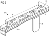
- figure 5 shows as a further exemplary embodiment an insulating element 30 with a carrier element 31, for example made of polyamide, which has a large number of circular penetrations 36, and one applied thereto expandable material 33.
- the thickness of the carrier material can be about 4 mm, as can that of the applied expandable material.
- the insulating element 30 is provided here with a fastening element 35, which is shaped here as a metal element, for example made of sheet metal, and can be connected to the cavity structure, for example by welding.
- any material that can be foamed in a controlled manner can be used as the foamable material.
- This material may or may not have reinforcing properties.
- the foamable material is foamed thermally, by moisture, or by electromagnetic radiation.
- foamable materials are one-component polyurethane compositions containing blowing agents, built up from crystalline polyesters containing OH groups in a mixture with others Polyols, preferably polyether polyols, and polyisocyanates with blocked isocyanate groups.
- the melting point of the crystalline polyester should be ⁇ 50 °C.
- the isocyanate groups of the polyisocyanate can be blocked, for example, with nucleophiles such as caprolactam, phenols or benzoxalones.
- blocked polyisocyanates such as are used, for example, in powder coating technology and are commercially available, for example, under the trade names Vestagon® BF 1350 and Vestagon® BF 1540 from Degussa GmbH, Germany.
- Isocyanates are also so-called encapsulated or surface-deactivated polyisocyanates, which are known to those skilled in the art and are described, for example, in EP 0 204 970 .
- Ethylene-vinyl acetate compositions containing blowing agents are also suitable as foamable materials.
Description
Die Erfindung betrifft ein Dämmelement zur akustischen Dämmung einer Durchdringung und/oder eines Hohlraums in einem Fahrzeug oder Gebäude, mit einem Trägerelement und einem expandierbaren Material. Sie betrifft des Weiteren die Verwendung eines solchen sowie Verfahren zur Dämmung.The invention relates to an insulating element for acoustically insulating a penetration and/or a cavity in a vehicle or building, with a carrier element and an expandable material. It also relates to the use of such and insulation methods.
Vielfach weisen Bauelemente, wie Karosserien und/oder Rahmen von Transport- und Fortbewegungsmitteln, insbesondere von Fahrzeugen zu Wasser oder zu Land oder von Luftfahrzeugen, Hohlräume auf, insbesondere um leichtgewichtige Konstruktionen zu ermöglichen. Diese Hohlräume verursachen jedoch verschiedenste Probleme. Je nach Art des Hohlraumes muss dieser zum Verhindern des Eindringens von Feuchtigkeit und Verschmutzungen, die zur Korrosion der Bauelemente führen können, abgedichtet werden. Oft ist es auch wünschenswert, die Hohlräume und somit das Bauelement wesentlich zu verstärken, jedoch das geringe Gewicht beizubehalten. Oft ist es auch notwendig, die Hohlräume und somit die Bauelemente zu stabilisieren, um Geräusche, die sonst den Hohlraum entlang oder durch diesen hindurch übertragen werden würden, zu reduzieren. Viele dieser Hohlräume weisen eine unregelmässige Form oder ein enges Ausmass auf, wodurch es erschwert wird, sie richtig abzudichten, zu verstärken und zu dämpfen.Components such as bodies and/or frames of means of transport and locomotion, in particular of vehicles on water or on land or of aircraft, often have cavities, in particular in order to enable lightweight constructions. However, these voids cause various problems. Depending on the type of cavity, it must be sealed to prevent the ingress of moisture and dirt, which can lead to corrosion of the components. It is often also desirable to significantly strengthen the cavities and thus the structural element, while maintaining the low weight. It is also often necessary to stabilize the cavities, and hence the components, to reduce noise that would otherwise be transmitted along or through the cavity. Many of these cavities are irregular in shape or narrow in size, making them difficult to properly seal, reinforce and cushion.
Insbesondere im Automobilbau, aber auch im Flugzeug- und Bootsbau, werden deshalb Abdichtungselemente (Englisch: baffle) verwendet, um Hohlräume abzudichten und/ oder akustisch abzuschotten, oder Verstärkungselemente (Englisch: reinforcer) verwendet, um Hohlräume zu verstärken. Auch für Dämmzwecke im Bauwesen werden expandierbare oder im Prozess des Einbringens bzw. Auftragens expandierende Materialien zu mannigfachen Zwecken eingesetzt, speziell zum Abdichten und zur akustischen Dämmung von Öffnungen oder Hohlräumen im Bereich der Hausinstallation oder der Gebäudehaut.In particular in automobile construction, but also in aircraft and boat construction, sealing elements (baffle) are therefore used to seal cavities and/or acoustically seal them off, or reinforcing elements (English: reinforcer) are used to reinforce cavities. Expandable materials or materials that expand in the process of being introduced or applied are also used for a variety of purposes for insulation purposes in construction, especially for sealing and for acoustic insulation of openings or cavities in the area of house installations or the building skin.
Aus der
Aus der
Die Druckschrift
Die
Der Erfindung liegt die Aufgabe zugrunde, ein verbessertes Dämmelement der oben erläuterten Art bereit zu stellen. Des Weiteren soll ein verbessertes Verfahren zur akustischen Dämmung einer Durchdringung und/oder eines Hohlraums bereitgestellt werden.The object of the invention is to provide an improved insulating element of the type explained above. Furthermore, an improved method for acoustically insulating a penetration and/or a cavity is to be provided.
Diese Aufgabe wird in ihrem Vorrichtungsaspekt durch ein expandierbares Dämmelement mit den Merkmalen des Anspruchs 1, in ihrem Verwendungsaspekt durch eine Verwendung mit den Merkmalen des Anspruchs 8 und in ihrem Verfahrensaspekt durch ein Verfahren mit den Merkmalen des Verfahrens-Anspruchs gelöst. Zweckmässige Fortbildungen des Erfindungsgedankens sind Gegenstand der anhängigen Ansprüche.This object is achieved in its device aspect by an expandable insulating element with the features of claim 1, in its use aspect by use with the features of claim 8 and in its method aspect by a method with the features of method claim. Appropriate developments of the inventive idea are the subject matter of the appended claims.
Ein Kerngedanke der vorliegenden Erfindung liegt darin, dass das expandierbare Material vor der Expansion nur eine (bzw. genau eine; Englisch: one) Oberfläche des Trägerelementes bedeckt, jedoch (zumindest teilweise) in die Durchdringungen eingebracht ist. Nach der Expansion bedeckt das expandierbare Material auch Abschnitte der anderen Oberfläche, auf der das expandierbare Material vor der Expansion nicht angeordnet war. Insbesondere die ursprüngliche Anordnung des expandierbaren Materials ist dadurch vergleichsweise einfach. Eine zuverlässige Fixierung des expandierbaren Materials wird auf synergistische Weise dadurch erreicht, dass dieses expandiert wird. Gleichzeitig wird ein Dämmelement mit einem hohen Schallabsorptionsgrad realisiert. Unter der "Oberfläche" des Trägerelements, die (im nicht-expandierten Zustand) bereits mit expandierbarem Material bedeckt ist, ist eine Oberfläche des Trägerelements zu verstehen, die sich bis zu einem Kantenbereich des Trägerelements erstreckt. Die Oberfläche des Trägerelements, die (nur im expandierten Zustand) mit expandierbarem Material bedeckt ist, liegt der Oberfläche des Trägerelements, die im nicht-expandierten Zustand mit expandierbarem Material bedeckt ist, gegenüber (und erstreckt sich ebenfalls bis zu einem Kantenbereich).A core idea of the present invention is that the expandable material before the expansion covers only one (or exactly one; English: one) surface of the carrier element, but (at least partially) into the Penetrations is introduced. After expansion, the expandable material also covers portions of the other surface where the expandable material was not located prior to expansion. In particular, the original arrangement of the expandable material is comparatively simple as a result. Reliable fixation of the expandable material is achieved in a synergistic manner by expanding it. At the same time, an insulating element with a high degree of sound absorption is realized. The "surface" of the carrier element which (in the non-expanded state) is already covered with expandable material means a surface of the carrier element which extends to an edge region of the carrier element. The surface of the support member that is covered with expandable material (only in the expanded state) faces the surface of the support member that is covered with expandable material in the unexpanded state (and also extends to an edge region).
In einer vorteilhaften Ausgestaltung des vorgeschlagenen (expandierbaren) Dämmelements erstreckt sich das expandierbare Material (im nicht-expandierten Zustand) in die Durchdringungen, insbesondere (im Wesentlichen) bis zur freien Oberfläche des flächigen Abschnitts (und nicht darüber hinaus). Dies ermöglicht die Bildung eines Dämmelementes, bei der das expandierbare Material zu einer geschlossenen Beschichtung genau einer Oberfläche des flächigen Abschnitts des Trägerelementes sowie auf Umfangsbereiche der der geschlossenen Beschichtung gegenüberliegenden Oberfläche expandiert ist.In an advantageous embodiment of the proposed (expandable) insulating element, the expandable material (in the non-expanded state) extends into the penetrations, in particular (essentially) up to the free surface of the flat section (and not beyond). This enables the formation of an insulating element in which the expandable material is expanded to form a closed coating on precisely one surface of the flat section of the carrier element and on peripheral areas of the surface opposite the closed coating.
Speziell ist die Beschichtung des Trägerelementes mit dem expandierbaren Material in der Vorprodukt-Stufe (im nicht-expandierten Zutsand) so ausgestaltet, dass beim Endprodukt (im expandierten Zustand) die der geschlossenen Beschichtung gegenüberliegende freie Oberfläche des flächigen Abschnitts des Trägerelementes zu mehr als 50%, insbesondere bis zu 75%, mit dem expandierten Material bedeckt ist. Die freie Oberfläche ist zu 50% bis 95% bedeckt, bevorzugt zu 50% bis 90% und besonders bevorzugt zu 60 bis 75% bedeckt.Specifically, the coating of the carrier element with the expandable material in the preliminary product stage (in the non-expanded state) is designed in such a way that in the end product (in the expanded state) the free surface of the planar section of the carrier element opposite the closed coating is more than 50% , in particular up to 75%, is covered with the expanded material. The free surface is closed 50% to 95% covered, preferably 50% to 90% and more preferably 60 to 75% covered.
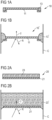
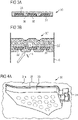
Grundsätzlich können die mit expandiertem Material bedeckten Umfangsbereiche der nicht ursprünglich mit expandierbarem Material bedeckten Oberfläche miteinander durch Materialbrücken verbunden sein bzw. teilweise ineinander übergehen. Wesentlich ist, dass auf dieser Oberfläche eine ausgeprägte Vertiefungs-Struktur vorliegt, die mehrere Wölbungen aufweist, die die Reflexion von dort auftreffenden Schallwellen infolge von Auslöschungseffekten wesentlich herabsetzt.In principle, the peripheral areas covered with expanded material of the surface not originally covered with expandable material can be connected to one another by material bridges or partially merge into one another. It is essential that there is a pronounced indentation structure on this surface, which has a number of bulges, which significantly reduces the reflection of sound waves impinging there as a result of cancellation effects.
Das Dämmelement weist ein ausgezeichnetes Leistungs-/Gewichts- und Leistungs-/Kosten-Verhältnis in Bezug auf seine akustischen Dämmeigenschaften auf.The insulation element has an excellent performance/weight and performance/cost ratio in relation to its acoustic insulation properties.
In einer weiteren Ausgestaltung der Erfindung besteht das Trägerelement aus einem Kunststoff, insbesondere aus einem Polyurethan, Polyamid, Poly(phenylenether), Polysulfon oder Polyethersulfon. Alternativ kann das Trägerelement aus einem gewachsenen organischen Material bestehen, insbesondere aus einem Holz- oder anderen Faserwerkstoff.In a further embodiment of the invention, the carrier element consists of a plastic, in particular of a polyurethane, polyamide, poly(phenylene ether), polysulfone or polyethersulfone. Alternatively, the carrier element can consist of a grown organic material, in particular of a wood or other fiber material.
Vorzugsweise ist das Trägerelement plattenförmig (also als Trägerplatte ausgebildet). In dieser Ausführungsform bildet eine erste Seite der Platte diejenige Oberfläche, die bereits im nicht-expandierten Zustand des Materials bedeckt ist und eine weitere (gegenüberliegende, in die entgegengesetzte Richtung weisende) Seite diejenige Oberfläche, die (nur) im expandierten Zustand des expandierbaren Materials mit diesem bedeckt ist. Zwischen den beiden Seiten befindet sich ein Plattenrand bzw. eine Plattenkante.The carrier element is preferably plate-shaped (ie designed as a carrier plate). In this embodiment, a first side of the panel forms that surface which is already covered in the non-expanded state of the material and a further (opposite, pointing in the opposite direction) side forms that surface which (only) is covered in the expanded state of the expandable material this is covered. There is a plate margin or a plate edge between the two sides.
Gemäß einer Weiterbildung wird ein expandierbares Dämmelement vorgeschlagen, wobei (im expandierten Zustand) eine Oberfläche des Trägerelementes mit einer geschlossenen Schicht und dessen andere, gegenüberliegende Oberfläche zumindest teilweise in umfangsnahen Bereichen der Durchdringungen mit expandiertem Material bedeckt ist.According to a development, an expandable insulating element is proposed, wherein (in the expanded state) one surface of the carrier element is covered with a closed layer and the other, opposite surface is at least partially covered with expanded material in the peripheral areas of the penetrations.
Vorzugsweise sind (im expandierten Zustand) auf der vollständig bedeckten Oberfläche des Trägerelements oberhalb der Durchdringungen Vertiefungen ausgebildet.Preferably (in the expanded state) depressions are formed on the completely covered surface of the carrier element above the penetrations.
In weiteren Ausgestaltungen der Erfindung ist vorgesehen, dass das expandierbare Material ein chemisches Treibmittel, beispielsweise Azodicarbonamid, Sulfohydrazid, Hydrogencarbonat oder dergleichen, oder ein physikalisches Treibmittel aufweist. In leicht mit kommerziell verfügbaren Ausgangsstoffen realisierbaren Ausführungen ist vorgesehen, dass das expandierbare Material eine einkomponentige Epoxidharz- oder Polyurethan- oder EVA- Zusammensetzung aufweist.In further configurations of the invention it is provided that the expandable material has a chemical blowing agent, for example azodicarbonamide, sulphohydrazide, hydrogen carbonate or the like, or a physical blowing agent. In versions that can easily be realized with commercially available starting materials, it is provided that the expandable material has a one-component epoxy resin or polyurethane or EVA composition.
Vorgeschlagen wird des Weiteren die Verwendung des oben spezifizierten erfindungsgemässen Dämmelementes zur akustischen Dämmung und/oder Verstärkung einer Öffnung und/oder eines Hohlraums eines Land-, Luft- oder Wasserfahrzeuges, insbesondere einer Aussenhülle desselben oder zur akustischen und/oder thermischen Dämmung von Bereichen, insbesondere einer Öffnung und/oder eines Hohlraumes, eines Gebäudes.It is also proposed to use the above-specified insulating element according to the invention for acoustically insulating and/or reinforcing an opening and/or a cavity in a land, air or water vehicle, in particular an outer shell of the same, or for acoustically and/or thermally insulating areas, in particular an opening and/or cavity, of a building.
Gemäß einem weiteren Aspekt der vorliegenden Erfindung wird ein Verfahren zur akustischen Dämmung und/oder Verstärkung einer Öffnung oder eines Hohlraums vorgeschlagen, wobei ein Dämmelement der oben beschriebenen Art in die Öffnung oder den Hohlraum eingebracht und anschließend das expandierbare Material expandiert wird.According to a further aspect of the present invention, a method for acoustically insulating and/or reinforcing an opening or a cavity is proposed, with an insulating element of the type described above being introduced into the opening or the cavity and the expandable material then being expanded.
Vorteile und Zweckmässigkeiten der Erfindung ergeben sich im Übrigen aus der nachfolgenden Beschreibung von Ausführungsbeispielen und -aspekten, teilweise anhand der Figuren. Von diesen zeigen:
- Fig. 1A und 1B
- schematische Darstellungen zur Erläuterung eines ersten akustischen Dämmungskonzeptes,
- Fig. 2A und 2B
- schematische Darstellungen zur Erläuterung eines zweiten akustischen Dämmungskonzeptes,
- Fig. 3A und 3B
- schematische Darstellung einer Ausführungsform des erfindungsgemässen Dämmelementes bzw. expandierten Dämmelementes (3B),
- Fig. 4A, 4B
- eine perspektivische Darstellung einer weiteren Ausführung des erfindungsgemässen Dämmelementes,
- Fig. 4C
- eine perspektivische Darstellung des Dämmelementes nach 4A und 4B in einer Einbausituation,
- Fig. 5
- perspektivische Darstellungen zur Erläuterung eines weiteren Ausführungsbeispiels der Erfindung.
- Figures 1A and 1B
- schematic representations to explain a first acoustic insulation concept,
- Figures 2A and 2B
- schematic representations to explain a second acoustic insulation concept,
- Figures 3A and 3B
- schematic representation of an embodiment of the inventive insulating element or expanded insulating element (3B),
- Figures 4A, 4B
- a perspective view of a further embodiment of the insulating element according to the invention,
- Figure 4C
- a perspective view of the insulating element according to 4A and 4B in an installation situation,
- figure 5
- perspective views to explain a further embodiment of the invention.
Es sind nur die für das unmittelbare Verständnis der Erfindung wesentlichen Elemente gezeigt. Gleichartige oder gleichwirkende Elemente sind mit dem gleichen Bezugszeichen versehen.Only the elements essential for a direct understanding of the invention are shown. Elements that are similar or have the same effect are provided with the same reference symbols.
Infolge dieser Vertiefungs-Struktur und des Fehlens ebener Oberflächen ergibt sich sowohl ein verringertes Reflexions- als auch Transmissionsvermögen für Schallwellen, was durch die in
Die Vielzahl von kreisförmigen Durchdringungen, Löchern 36 im Trägerelement, welches in diesem Beispiel aus 4,5 mm dickem PA 6.6, besteht und der Anteil der Durchdringungen beträgt ca. 30 bis 40% der Gesamtfläche des Trägerelementes. Als aufschäumbares Material wird beispielsweise ein elastisch aufschäumendes Polyurethan mit einer Schichtdicke von 4 mm aufgebracht, welches nach dem Aufschäumen des expandierbaren Materials vorzugsweise eine Dicke zwischen 30 und 40 mm annehmen kann.The multiplicity of circular penetrations, holes 36 in the carrier element, which in this example consists of 4.5 mm thick PA 6.6, and the proportion of penetrations is approximately 30 to 40% of the total area of the carrier element. For example, an elastically foaming polyurethane with a layer thickness of 4 mm is applied as the foamable material, which can preferably assume a thickness of between 30 and 40 mm after the foaming of the expandable material.
Es versteht sich, dass sich das erfindungsgemässe Konzept in vielgestaltigen anderen Konfiguration, und u. a. mit mehrteiligen und räumlich komplex geformten Trägerelementen, realisieren lässt.It goes without saying that the concept according to the invention can be used in a variety of other configurations, and e.g. with multi-part and spatially complex shaped carrier elements.
Als schäumbares Material kann grundsätzlich jedes beliebige Material eingesetzt werden, das kontrolliert zur Schäumung gebracht werden kann. Dieses Material kann dabei Verstärkungseigenschaften aufweisen oder auch nicht. Typischerweise wird das schäumbare Material thermisch, durch Feuchtigkeit oder durch elektromagnetische Strahlung geschäumt.In principle, any material that can be foamed in a controlled manner can be used as the foamable material. This material may or may not have reinforcing properties. Typically, the foamable material is foamed thermally, by moisture, or by electromagnetic radiation.
Ein solches schäumbares Material weist typischerweise ein chemisches oder ein physikalisches Treibmittel auf. Chemische Treibmittel sind organische oder anorganische Verbindungen, welche sich unter Einfluss von Temperatur, Feuchtigkeit, oder elektromagnetischer Strahlung zersetzen, wobei mindestens eines der Zersetzungsprodukte ein Gas ist. Als physikalische Treibmittel können beispielsweise Verbindungen eingesetzt werden, welche bei Erhöhung der Temperatur in den gasförmigen Aggregatszustand übergehen. Dadurch sind sowohl chemische als auch physikalische Treibmittel in der Lage Schaumstrukturen in Polymeren zu erzeugen.Such a foamable material typically has a chemical or a physical blowing agent. Chemical blowing agents are organic or inorganic compounds which decompose under the influence of temperature, humidity or electromagnetic radiation, with at least one of the decomposition products being a gas. As a physical blowing agent For example, compounds can be used which change to the gaseous state of aggregation when the temperature is increased. As a result, both chemical and physical blowing agents are able to create foam structures in polymers.
Bevorzugt wird das schäumbare Material thermisch geschäumt wobei chemische Treibmittel eingesetzt werden. Als chemische Treibmittel eignen sich beispielsweise Azodicarbonamide, Sulfohydrazide, Hydrogencarbonate oder Carbonate. Geeignete Treibmittel sind beispielsweise auch kommerziell erhältlich unter dem Handelsnamen Expancel® von der Firma Akzo Nobel, Niederlande, oder unter dem Handelsnamen Celogen® von der Firma Chemtura Corp., USA. Die für die Schäumung erforderliche Wärme kann durch externe oder durch interne Wärmequellen, wie einer exothermen chemischen Reaktion, eingebracht werden. Das schäumbare Material ist vorzugsweise bei einer Temperatur von ≤ 160 °C, insbesondere von 80 °C bis 150 °C, bevorzugt von 90 °C bis 140 °C, schäumbar.The foamable material is preferably thermally foamed using chemical blowing agents. Examples of suitable chemical blowing agents are azodicarbonamides, sulfohydrazides, bicarbonates or carbonates. Suitable blowing agents are also commercially available, for example, under the trade name Expancel® from Akzo Nobel, Netherlands, or under the trade name Celogen® from Chemtura Corp., USA. The heat required for foaming can be introduced by external or by internal heat sources, such as an exothermic chemical reaction. The foamable material is preferably foamable at a temperature of ≦160° C., in particular from 80° C. to 150° C., preferably from 90° C. to 140° C.
Als schäumbare Materialien geeignet sind beispielsweise einkomponentige bei Raumtemperatur nicht fliessende Epoxidharzsysteme, welche insbesondere eine erhöhte Schlagzähigkeit aufweisen und Thixotropiermittel wie Aerosile oder Nanoclays enthalten. Beispielsweise weisen derartige Epoxidharzsysteme 20 bis 50 Gew.-% eines Epoxid-Füssigharzes, 0 bis 30 Gew.-% eines Epoxid-Festharzes, 5 bis 30 Gew.-% Zähigkeitsmodifikatoren, 1 bis 5 Gew.-% physikalische oder chemische Triebmittel, 10 bis 40 Gew.-% Füllstoffe, 1 bis 10 Gew.-% Thixotropiermittel und 2 bis 10 Gew.-% hitzeaktivierbare Härter auf. Als Zähigkeitsmodifikatoren eignen sich reaktive Flüssigkautschuke auf Basis von Nitrilkautschuk oder Derivate von Polyetherpolyol-Polyurethanen, Core-Shell Polymere und ähnliche dem Fachmann bekannte Systeme.Suitable foamable materials are, for example, one-component epoxy resin systems which do not flow at room temperature, which in particular have increased impact strength and contain thixotropic agents such as aerosils or nanoclays. For example, such epoxy resin systems have 20 to 50% by weight of a liquid epoxy resin, 0 to 30% by weight of a solid epoxy resin, 5 to 30% by weight of toughness modifiers, 1 to 5% by weight of physical or chemical blowing agents, 10 up to 40% by weight of fillers, 1 to 10% by weight of thixotropic agents and 2 to 10% by weight of heat-activatable hardeners. Reactive liquid rubbers based on nitrile rubber or derivatives of polyetherpolyol-polyurethanes, core-shell polymers and similar systems known to the person skilled in the art are suitable as toughness modifiers.
Ebenfalls geeignete schäumbare Materialien sind Treibmittel enthaltende einkomponentige Poly¬urethan¬zusammensetzungen, aufgebaut aus kristallinen, OH-Gruppen aufweisenden Polyestern im Gemisch mit weiteren Polyolen, vorzugsweise Polyetherpolyolen, und Polyisocyanaten mit blockierten Isocyanatgruppen. Der Schmelzpunkt des kristallinen Polyesters sollte ≥ 50 °C sein. Die Isocyanatgruppen des Polyisocyanats können beispielsweise mit Nucleophilen wie Caprolactam, Phenolen oder Benzoxalonen blockiert sein. Weiterhin eignen sich blockierte Polysocyanate wie sie beispielsweise in der Pulverlacktechnologie zum Einsatz kommen und beispielsweise unter den Handelsnamen Vestagon® BF 1350 und Vestagon® BF 1540 kommerziell erhältlich sind von Degussa GmbH, Deutschland. Als Isocyanate sind ebenfalls so genannte verkapselte oder oberflächendeaktivierte Polyisocyanate, welche dem Fachmann bekannt und beispielsweise beschreiben sind in
Weiterhin eignen sich als schäumbare Materialien Treibmittel enthaltende zweikomponentige Epoxid/Polyurethan-Zusammensetzungen wie sie beispielsweise beschrieben sind in
Weiterhin eignen sich als schäumbare Materialien Treibmittel enthaltende Ethylen-Vinyl-Acetat-Zusammensetzungen.Ethylene-vinyl acetate compositions containing blowing agents are also suitable as foamable materials.
Ebenfalls geeignete schäumbare Materialien werden beispielsweise unter dem Handelsnamen SikaBaffle® 240, SikaBaffle® 250 oder SikaBaffle® 255 von der Sika Corp., USA, vertrieben und sind in den Patenten
Solche schäumbaren Materialien sind für die vorliegende Erfindung besonders bevorzugt.Such foamable materials are particularly preferred for the present invention.
Als schäumbare Materialien mit Verstärkungseigenschaften sind beispielsweise diejenigen bevorzugt, welche unter dem Handelsnamen SikaReinforcer® 941 von der Sika Corp., USA, vertrieben werden. Diese sind beschrieben in
Das Trägerelement kann aus beliebigen Materialien bestehen. Bevorzugte Materialien sind Kunststoffe, insbesondere Polyurethane, Polyamide, Polyester und Polyolefine, bevorzugt hochtemperaturbeständige Polymere wie Poly(phenylenether), Polysulfone oder Polyethersulfone, welche insbesondere auch geschäumt sind; Metalle, insbesondere Aluminium und Stahl; oder gewachsene organische Materialien, insbesondere Holz- oder andere (gepresste) Faserwerkstoffe oder glasartige oder keramische Materialien; speziell auch geschäumte Materialien dieser Art; oder beliebige Kombinationen dieser Materialien. Besonders bevorzugt wird Polyamid, insbesondere Polyamid 6, Polyamid 6,6, Polyamid 11, Polyamid 12 oder ein Gemisch davon verwendet.The carrier element can consist of any materials. Preferred materials are plastics, in particular polyurethanes, polyamides, polyesters and polyolefins, preferably high-temperature-resistant polymers such as poly(phenylene ether), polysulfones or polyether sulfones, which in particular are also foamed; metals, in particular aluminum and steel; or grown organic materials, in particular wood or other (pressed) fiber materials or vitreous or ceramic materials; specifically also foamed materials of this type; or any combination of these materials. Polyamide, in particular polyamide 6, polyamide 6.6, polyamide 11, polyamide 12 or a mixture thereof is particularly preferably used.
Weiterhin kann das Trägerelement einen beliebigen Aufbau und eine beliebige Struktur aufweisen. Es kann beispielsweise massiv, hohl, oder geschäumt sein oder eine gitterartige Struktur aufweisen. Die Oberfläche des Trägerelements kann typischerweise glatt, rau oder strukturiert sein.Furthermore, the carrier element can have any desired design and any desired structure. For example, it can be solid, hollow, or foamed, or have a lattice-like structure. The surface of the carrier element can typically be smooth, rough or structured.
Bei erfindungsgemässen Abdichtungs- und Verstärkungselementen, bei welchen sich das schäumbare Material auf einem Trägerelement befindet, unterscheidet sich das Herstellungsverfahren dementsprechend, ob das Trägerelement aus einem durch Spritzguss verarbeitbaren Material besteht oder nicht. Ist dies der Fall, wird üblicherweise ein Zweikomponenten-Spritzgussverfahren eingesetzt. Dabei wird zuerst eine erste Komponente, in diesem Fall das Trägerelement, gespritzt. Nach Erstarren dieser ersten Komponente wird die Kavität im Werkzeug vergrössert, bzw. angepasst, oder der hergestellte Spritzling wird in ein neues Werkzeug gelegt, und eine zweite Komponente, in diesem Fall das schäumbare Material, wird mit einem zweiten Spritzaggregat an die erste Komponente angespritzt.In the case of sealing and reinforcing elements according to the invention, in which the foamable material is located on a carrier element, the manufacturing process differs according to whether the carrier element consists of a material that can be processed by injection molding or not. If this is the case, a two-component injection molding process is usually used. In this case, a first component, in this case the carrier element, is injected first. After this first component has solidified, the cavity in the mold is enlarged or adjusted, or the molded part produced is placed in a new mold and a second component, in this case the foamable material, is injected onto the first component with a second injection unit.
Besteht das Trägerelement aus einem Material, welches sich nicht durch das Spritzgussverfahren herstellen lässt, also beispielsweise aus einem Metall, wird das Trägerelement in ein entsprechendes Werkzeug gelegt und das schäumbare Material wird an das Trägerelement angespritzt. Selbstverständlich besteht auch die Möglichkeit das schäumbare Material durch spezielle Befestigungsmittel oder -verfahren an dem Trägerelement zu befestigen.If the carrier element consists of a material that cannot be produced by injection molding, for example a metal, the carrier element is placed in a corresponding tool and the foamable material is injected onto the carrier element. Of course, there is also the possibility of attaching the foamable material to the carrier element using special attachment means or methods.
Selbstverständlich ist die Erfindung nicht auf das gezeigte und beschriebene Ausführungsbeispiel beschränkt. Die Befestigungslemente können beliebig ausgestaltete werden und es können diese auch in den Figuren ausgetauscht werden.Of course, the invention is not limited to the embodiment shown and described. The fastening elements can be configured as desired and they can also be exchanged in the figures.
- 10; 20; 3010; 20; 30
- Dämmelementinsulating element
- 10';20';30'10';20';30'
- Expandiertes DämmelementExpanded insulating element
- 11; 21; 3111; 21; 31
- Trägerelementcarrier element
- 31a31a
- Trägerelement RandbereichSupport element edge area
- 3232
- Freie Oberfläche von 31Free surface of 31
- 13;23;3313;23;33
- Expandierbares MaterialExpandable material
- 13';23';33'13';23';33'
- Expandiertes Materialexpanded material
- 34, 3534, 35
- Befestigungselementfastener
- 3636
- Durchdringungpenetration
- 37a, 37b37a, 37b
- Begrenzung Hohlraumboundary cavity
- CC
- Hohlraumcavity
- RR
- Reflektierte SchallwellenReflected sound waves
- TT
- Transmittierte SchallwellenTransmitted sound waves
Claims (9)
- Expandable insulating element (30) for acoustically insulating an opening and/or a cavity in a vehicle or building, having a carrier element (31) and an expandable material (33), wherein the carrier element (31) has multiple apertures (36), wherein, in the non-expanded state, only one surface of the carrier element (31) is at least partially covered with expandable material (33), wherein the expandable material (33), in the expanded state, is expanded over peripheral regions of that surface (32) of the carrier element (31) that is opposite the surface of the carrier element (31) at least partially covered with expandable material (33), characterized in that, in the non-expanded state, the expandable material (33) at least partially fills the apertures (36), wherein the surface-area proportion of the apertures (36) amounts to 20% to 70% of the overall surface of the carrier element, and wherein the opposite surface (32) is 50% to 95% covered with expandable material (33').
- Expandable insulating element according to Claim 1, characterized in that the expandable material (33) extends into the apertures (36) substantially as far as the free surface of the carrier element (31) in the non-expanded state.
- Expandable insulating element according to one of the preceding claims, characterized in that the apertures (36) have a spherical or elliptical shape, in particular a round shape.
- Expandable insulating element according to one of the preceding claims, characterized in that the carrier element (31) has an edge region (31a) with a tapered cross section.
- Expandable insulating element according to one of the preceding claims, characterized in that the carrier element is plate shaped.
- Expandable insulating element according to one of the preceding claims, characterized in that, in the expanded state, one surface of the carrier element (31) is covered with a closed layer and its other, opposite surface (32) is covered with expanded material (33') at least partially in regions of the apertures (36) that are close to the periphery.
- Expandable insulating element according to one of the preceding claims, characterized in that, in the expanded state, recesses are formed on the completely covered surface of the carrier element (31) above the apertures (36).
- Use of an insulating element (30) according to one of the preceding claims for acoustically insulating and/or reinforcing an opening and/or a cavity in a land, air or water vehicle, and/or a cavity in a building.
- Method for acoustically insulating and/or reinforcing an opening or a cavity, characterized in that an insulating element (30) according to one of Claims 1 to 7 is introduced into the opening or the cavity and then the expandable material (33) is expanded.
Priority Applications (2)
| Application Number | Priority Date | Filing Date | Title |
|---|---|---|---|
| EP13803057.2A EP2936481B1 (en) | 2012-12-21 | 2013-12-13 | Expandable damping element, use thereof and method for damping or strengthening |
| EP22196501.5A EP4145441A1 (en) | 2012-12-21 | 2013-12-13 | Insulating element, expanded insulating element, use of such an element and method for insulating |
Applications Claiming Priority (3)
| Application Number | Priority Date | Filing Date | Title |
|---|---|---|---|
| EP12198960 | 2012-12-21 | ||
| PCT/EP2013/076522 WO2014095620A1 (en) | 2012-12-21 | 2013-12-13 | Insulation element, expanded insulation element, use of same and method for insulation |
| EP13803057.2A EP2936481B1 (en) | 2012-12-21 | 2013-12-13 | Expandable damping element, use thereof and method for damping or strengthening |
Related Child Applications (2)
| Application Number | Title | Priority Date | Filing Date |
|---|---|---|---|
| EP22196501.5A Division EP4145441A1 (en) | 2012-12-21 | 2013-12-13 | Insulating element, expanded insulating element, use of such an element and method for insulating |
| EP22196501.5A Division-Into EP4145441A1 (en) | 2012-12-21 | 2013-12-13 | Insulating element, expanded insulating element, use of such an element and method for insulating |
Publications (2)
| Publication Number | Publication Date |
|---|---|
| EP2936481A1 EP2936481A1 (en) | 2015-10-28 |
| EP2936481B1 true EP2936481B1 (en) | 2023-02-08 |
Family
ID=47603096
Family Applications (2)
| Application Number | Title | Priority Date | Filing Date |
|---|---|---|---|
| EP22196501.5A Pending EP4145441A1 (en) | 2012-12-21 | 2013-12-13 | Insulating element, expanded insulating element, use of such an element and method for insulating |
| EP13803057.2A Active EP2936481B1 (en) | 2012-12-21 | 2013-12-13 | Expandable damping element, use thereof and method for damping or strengthening |
Family Applications Before (1)
| Application Number | Title | Priority Date | Filing Date |
|---|---|---|---|
| EP22196501.5A Pending EP4145441A1 (en) | 2012-12-21 | 2013-12-13 | Insulating element, expanded insulating element, use of such an element and method for insulating |
Country Status (7)
| Country | Link |
|---|---|
| US (1) | US9611638B2 (en) |
| EP (2) | EP4145441A1 (en) |
| JP (1) | JP6320412B2 (en) |
| KR (1) | KR102275223B1 (en) |
| CN (1) | CN104885148A (en) |
| ES (1) | ES2938872T3 (en) |
| WO (1) | WO2014095620A1 (en) |
Families Citing this family (15)
| Publication number | Priority date | Publication date | Assignee | Title |
|---|---|---|---|---|
| US7913467B2 (en) * | 2006-07-25 | 2011-03-29 | Zephyros, Inc. | Structural reinforcements |
| BR112015027052B1 (en) * | 2013-04-26 | 2021-08-10 | Zephyros, Inc | ACTIVE INSERT FOR INSERTION IN A CAVITY OF AN AUTOMOTIVE VEHICLE AND METHOD OF MANUFACTURING THE ACTIVE INSERT |
| WO2016077820A1 (en) * | 2014-11-14 | 2016-05-19 | Zephyros, Inc. | Multi-shot injection molded method and product |
| DE102015219453A1 (en) * | 2015-10-08 | 2017-04-13 | Bayerische Motoren Werke Aktiengesellschaft | Method for producing a foam-filled hollow profile |
| CN108883795B (en) | 2016-03-18 | 2021-07-27 | Sika技术股份公司 | Isolation element |
| US10843641B2 (en) | 2016-04-22 | 2020-11-24 | Sika Technology Ag | Insulating element |
| EP3254939B1 (en) | 2016-06-10 | 2021-09-01 | Sika Technology AG | Baffle |
| EP3263425B1 (en) * | 2016-06-27 | 2020-08-12 | Sika Technology AG | Insulation element |
| EP3611081B1 (en) * | 2018-08-13 | 2023-05-03 | Sika Technology Ag | Device for reinforcing, sealing or damping of a structural element |
| EP3844052B1 (en) * | 2018-08-31 | 2022-08-03 | Sika Technology AG | System for insulation of a structural element |
| EP4223618A3 (en) * | 2018-08-31 | 2023-08-23 | Sika Technology AG | System for insulation of a structural element |
| CN112638753B (en) * | 2018-08-31 | 2024-02-13 | Sika技术股份公司 | Device for reinforcing, sealing or damping a structural element |
| EP4041618A1 (en) * | 2019-10-08 | 2022-08-17 | Sika Technology AG | Insulating element |
| FR3122098B1 (en) * | 2021-04-26 | 2023-06-16 | Speedinnov | Vehicle interior fire barrier |
| EP4140687A1 (en) * | 2021-08-23 | 2023-03-01 | Otrajet Inc. | Article and method of manufacturing the same |
Citations (21)
| Publication number | Priority date | Publication date | Assignee | Title |
|---|---|---|---|---|
| US5196253A (en) | 1990-01-22 | 1993-03-23 | Matec Holdikng Ag | Sound absorbing heat shield with perforate support layer |
| JP2000052445A (en) * | 1998-08-06 | 2000-02-22 | Neoex Lab Inc | Hollow chamber shut-off tool in hollow structure |
| WO2000027920A1 (en) | 1998-11-05 | 2000-05-18 | Sika Corporation | Sound deadening and structural reinforcement compositions and methods of using the same |
| US6093358A (en) | 1998-01-27 | 2000-07-25 | Lear Corporation | Method of making an expandable gap filling product |
| EP1149679A2 (en) | 2000-04-26 | 2001-10-31 | Neo-Ex Lab. Inc. | Devices and structures for reinforcing hollow structural members |
| WO2001083206A1 (en) | 2000-05-01 | 2001-11-08 | Sika Corporation | Baffle and reinforcement assembly |
| US6382635B1 (en) | 2000-03-17 | 2002-05-07 | Sika Corporation | Double walled baffle |
| EP1362683A2 (en) | 2002-05-17 | 2003-11-19 | L & L Products Inc. | Improved baffle precursors |
| US20050285292A1 (en) | 2004-06-15 | 2005-12-29 | L&L Products, Inc. | Laminar mouldings |
| US20060008615A1 (en) | 2004-06-21 | 2006-01-12 | L&L Products, Inc. | Overmoulding |
| WO2008043385A1 (en) | 2006-10-13 | 2008-04-17 | Henkel Ag & Co. Kgaa | Acoustic absorbing member with different types of pores |
| US7469459B2 (en) | 2003-09-18 | 2008-12-30 | Zephyros, Inc. | System and method employing a porous container for sealing, baffling or reinforcing |
| WO2009049886A1 (en) | 2007-10-17 | 2009-04-23 | Zephyros Inc | Multifunctional vehicle components |
| US20090111371A1 (en) | 2007-10-24 | 2009-04-30 | Niezur Michael C | Exhauster baffle |
| WO2009114417A2 (en) | 2008-03-07 | 2009-09-17 | Henkel Ag & Co. Kgaa. | Acoustic baffle assembly |
| EP2147848A1 (en) | 2008-07-25 | 2010-01-27 | Sika Technology AG | Interconnected foam or adhesive layers |
| EP2154051A1 (en) | 2008-08-05 | 2010-02-17 | Sika Technology AG | Baffle |
| WO2010060241A1 (en) | 2008-11-26 | 2010-06-03 | Dow Global Technologies Inc. | Acoustic baffle members and methods for applying acoustic baffles in cavities |
| WO2011146793A1 (en) | 2010-05-21 | 2011-11-24 | Zephyros,Inc. | Method for application of structural materials |
| US8087916B2 (en) | 2005-12-15 | 2012-01-03 | Cemedine Henkel Co., Ltd. | Holding jig for a foamable material |
| US20120146296A1 (en) | 2010-12-08 | 2012-06-14 | Zephyros, Inc. | Sealing assembly |
Family Cites Families (21)
| Publication number | Priority date | Publication date | Assignee | Title |
|---|---|---|---|---|
| GB1372186A (en) | 1970-09-25 | 1974-10-30 | Ici Ltd | Fluid jet apparatus for treating and transporting yarns |
| JPS57151347A (en) * | 1981-03-16 | 1982-09-18 | Nissan Motor | Reinforcing material for reinforcing board material |
| DE3517333A1 (en) | 1985-05-14 | 1986-11-20 | Basf Ag, 6700 Ludwigshafen | METHOD FOR PRODUCING STABLE DISPERSIONS OF FINE PARTICULATE POLYISOCYANATES AND THE USE THEREOF |
| US5266133A (en) | 1993-02-17 | 1993-11-30 | Sika Corporation | Dry expansible sealant and baffle composition and product |
| US5506025A (en) * | 1995-01-09 | 1996-04-09 | Sika Corporation | Expandable baffle apparatus |
| JP2721327B2 (en) * | 1995-02-09 | 1998-03-04 | 株式会社ネオックスラボ | Support structure of foamable material in hollow structure |
| US5755486A (en) * | 1995-05-23 | 1998-05-26 | Novamax Technologies Holdings, Inc. | Composite structural reinforcement member |
| US5904024A (en) * | 1997-02-26 | 1999-05-18 | Axxis Corp. | Mount construction of foam substrate in hollow structures |
| US6103341A (en) * | 1997-12-08 | 2000-08-15 | L&L Products | Self-sealing partition |
| US6347799B1 (en) * | 1999-04-01 | 2002-02-19 | Tyco Electronics Corporation | Cavity sealing article having improved sag resistance |
| FR2841848B1 (en) * | 2002-07-03 | 2005-02-11 | Joint Francais | ASSEMBLY OF ACOUSTIC INSULATION FOR MOUNTING INTO A TUBULAR PIECE AND TUBULAR PIECE EQUIPPED WITH SUCH ASSEMBLIES, IN PARTICULAR A MOTOR PIECE |
| US7045090B2 (en) * | 2003-06-06 | 2006-05-16 | Bayer Materialscience Llc | Method of preparing an article |
| CN1863656A (en) * | 2003-09-18 | 2006-11-15 | L&L产品公司 | System and method of employing a porous container for sealing, baffling or reinforcing |
| EP1568749A1 (en) | 2004-02-25 | 2005-08-31 | Sika Technology AG | Two-component adhesive for producing semi-finished products and sandwich composites |
| JP2006007941A (en) * | 2004-06-24 | 2006-01-12 | Cemedine Henkel Co Ltd | Holding fixture for foamed material, void filling tool for hollow structure and auxiliary void filling tool |
| US7597382B2 (en) * | 2005-06-07 | 2009-10-06 | Zephyros, Inc. | Noise reduction member and system |
| US7926179B2 (en) * | 2005-08-04 | 2011-04-19 | Zephyros, Inc. | Reinforcements, baffles and seals with malleable carriers |
| US7823693B2 (en) * | 2008-06-28 | 2010-11-02 | Deere & Company | Vehicle interior panel assembly |
| EP2360002A1 (en) * | 2010-02-11 | 2011-08-24 | Sika Technology AG | Baffle or reinforcer with fixation mechanism |
| US8967327B2 (en) * | 2012-03-20 | 2015-03-03 | Zephyros, Inc. | Baffle assembly |
| EP2883781A1 (en) * | 2013-12-13 | 2015-06-17 | Sika Technology AG | Lightweight baffle or reinforcement element and method for producing such a lightweight baffle or reinforcement element |
-
2013
- 2013-12-13 WO PCT/EP2013/076522 patent/WO2014095620A1/en active Application Filing
- 2013-12-13 JP JP2015548385A patent/JP6320412B2/en active Active
- 2013-12-13 EP EP22196501.5A patent/EP4145441A1/en active Pending
- 2013-12-13 KR KR1020157015786A patent/KR102275223B1/en active IP Right Grant
- 2013-12-13 EP EP13803057.2A patent/EP2936481B1/en active Active
- 2013-12-13 ES ES13803057T patent/ES2938872T3/en active Active
- 2013-12-13 US US14/654,150 patent/US9611638B2/en active Active
- 2013-12-13 CN CN201380066324.9A patent/CN104885148A/en active Pending
Patent Citations (21)
| Publication number | Priority date | Publication date | Assignee | Title |
|---|---|---|---|---|
| US5196253A (en) | 1990-01-22 | 1993-03-23 | Matec Holdikng Ag | Sound absorbing heat shield with perforate support layer |
| US6093358A (en) | 1998-01-27 | 2000-07-25 | Lear Corporation | Method of making an expandable gap filling product |
| JP2000052445A (en) * | 1998-08-06 | 2000-02-22 | Neoex Lab Inc | Hollow chamber shut-off tool in hollow structure |
| WO2000027920A1 (en) | 1998-11-05 | 2000-05-18 | Sika Corporation | Sound deadening and structural reinforcement compositions and methods of using the same |
| US6382635B1 (en) | 2000-03-17 | 2002-05-07 | Sika Corporation | Double walled baffle |
| EP1149679A2 (en) | 2000-04-26 | 2001-10-31 | Neo-Ex Lab. Inc. | Devices and structures for reinforcing hollow structural members |
| WO2001083206A1 (en) | 2000-05-01 | 2001-11-08 | Sika Corporation | Baffle and reinforcement assembly |
| EP1362683A2 (en) | 2002-05-17 | 2003-11-19 | L & L Products Inc. | Improved baffle precursors |
| US7469459B2 (en) | 2003-09-18 | 2008-12-30 | Zephyros, Inc. | System and method employing a porous container for sealing, baffling or reinforcing |
| US20050285292A1 (en) | 2004-06-15 | 2005-12-29 | L&L Products, Inc. | Laminar mouldings |
| US20060008615A1 (en) | 2004-06-21 | 2006-01-12 | L&L Products, Inc. | Overmoulding |
| US8087916B2 (en) | 2005-12-15 | 2012-01-03 | Cemedine Henkel Co., Ltd. | Holding jig for a foamable material |
| WO2008043385A1 (en) | 2006-10-13 | 2008-04-17 | Henkel Ag & Co. Kgaa | Acoustic absorbing member with different types of pores |
| WO2009049886A1 (en) | 2007-10-17 | 2009-04-23 | Zephyros Inc | Multifunctional vehicle components |
| US20090111371A1 (en) | 2007-10-24 | 2009-04-30 | Niezur Michael C | Exhauster baffle |
| WO2009114417A2 (en) | 2008-03-07 | 2009-09-17 | Henkel Ag & Co. Kgaa. | Acoustic baffle assembly |
| EP2147848A1 (en) | 2008-07-25 | 2010-01-27 | Sika Technology AG | Interconnected foam or adhesive layers |
| EP2154051A1 (en) | 2008-08-05 | 2010-02-17 | Sika Technology AG | Baffle |
| WO2010060241A1 (en) | 2008-11-26 | 2010-06-03 | Dow Global Technologies Inc. | Acoustic baffle members and methods for applying acoustic baffles in cavities |
| WO2011146793A1 (en) | 2010-05-21 | 2011-11-24 | Zephyros,Inc. | Method for application of structural materials |
| US20120146296A1 (en) | 2010-12-08 | 2012-06-14 | Zephyros, Inc. | Sealing assembly |
Non-Patent Citations (1)
| Title |
|---|
| BUTLER MARK, ET AL: "Using Terocore® Brand Structural Foam to Improve Bumper Beam Design", SAE TECHNICAL PAPER SERIES, vol. 2002-01-2018, 1 January 2002 (2002-01-01), pages 1 - 11, XP093104436 |
Also Published As
| Publication number | Publication date |
|---|---|
| EP4145441A1 (en) | 2023-03-08 |
| JP2016502149A (en) | 2016-01-21 |
| KR102275223B1 (en) | 2021-07-09 |
| ES2938872T3 (en) | 2023-04-17 |
| KR20150096405A (en) | 2015-08-24 |
| JP6320412B2 (en) | 2018-05-09 |
| CN104885148A (en) | 2015-09-02 |
| US20150315782A1 (en) | 2015-11-05 |
| EP2936481A1 (en) | 2015-10-28 |
| US9611638B2 (en) | 2017-04-04 |
| WO2014095620A1 (en) | 2014-06-26 |
Similar Documents
| Publication | Publication Date | Title |
|---|---|---|
| EP2936481B1 (en) | Expandable damping element, use thereof and method for damping or strengthening | |
| EP3797060B1 (en) | Insulation element | |
| DE60201491T2 (en) | MASS DEVICE TOLERANT STRUCTURAL EQUIPMENT AND ITS APPLICATION | |
| DE60131874T2 (en) | SIDE IMPACT GAIN | |
| EP2236358A1 (en) | Element for sealing or strengthening of a cavity and method for introducing a penetration element in such an element | |
| EP3445642B1 (en) | Insulation element | |
| EP3429909B1 (en) | Baffle | |
| EP3263425B1 (en) | Insulation element | |
| EP3551503B1 (en) | Printed insulating element | |
| WO2020193381A1 (en) | Insulating element | |
| EP3659900B1 (en) | Insulating element for a structural element of a motor vehicle | |
| EP4186677A1 (en) | Method for the preparation of insulating elements | |
| EP2261104A1 (en) | Element for sealing or reinforcing a cavity and method for inserting such an element into the cavity of a structural element | |
| EP2151369A1 (en) | Seal section made from foamable material | |
| EP3230036B1 (en) | Component for separating and/or delimiting a cavity | |
| EP4155173A1 (en) | Reinforcement element for reinforcing a structural element | |
| WO2022258786A1 (en) | Insulating element | |
| WO2024012969A1 (en) | Insulating element | |
| EP4155172A1 (en) | Reinforcement element for reinforcing a structural element | |
| EP4227195A1 (en) | System of a structural element with an insulating element arranged therein | |
| EP4273028A1 (en) | Insulating element | |
| EP4163190A1 (en) | System of an insulated structural element | |
| EP3560798A1 (en) | Insulation element | |
| WO2022053463A1 (en) | Insulating element | |
| EP2423050A1 (en) | Fastening element and process to fasten an element to or in a part with a fastening element |
Legal Events
| Date | Code | Title | Description |
|---|---|---|---|
| PUAI | Public reference made under article 153(3) epc to a published international application that has entered the european phase |
Free format text: ORIGINAL CODE: 0009012 |
|
| 17P | Request for examination filed |
Effective date: 20150721 |
|
| AK | Designated contracting states |
Kind code of ref document: A1 Designated state(s): AL AT BE BG CH CY CZ DE DK EE ES FI FR GB GR HR HU IE IS IT LI LT LU LV MC MK MT NL NO PL PT RO RS SE SI SK SM TR |
|
| AX | Request for extension of the european patent |
Extension state: BA ME |
|
| DAX | Request for extension of the european patent (deleted) | ||
| STAA | Information on the status of an ep patent application or granted ep patent |
Free format text: STATUS: EXAMINATION IS IN PROGRESS |
|
| 17Q | First examination report despatched |
Effective date: 20181031 |
|
| GRAP | Despatch of communication of intention to grant a patent |
Free format text: ORIGINAL CODE: EPIDOSNIGR1 |
|
| STAA | Information on the status of an ep patent application or granted ep patent |
Free format text: STATUS: GRANT OF PATENT IS INTENDED |
|
| RIC1 | Information provided on ipc code assigned before grant |
Ipc: B60R 13/08 20060101ALI20201124BHEP Ipc: G10K 11/16 20060101AFI20201124BHEP Ipc: B29C 44/12 20060101ALI20201124BHEP Ipc: B29C 44/18 20060101ALI20201124BHEP |
|
| INTG | Intention to grant announced |
Effective date: 20201210 |
|
| GRAJ | Information related to disapproval of communication of intention to grant by the applicant or resumption of examination proceedings by the epo deleted |
Free format text: ORIGINAL CODE: EPIDOSDIGR1 |
|
| STAA | Information on the status of an ep patent application or granted ep patent |
Free format text: STATUS: EXAMINATION IS IN PROGRESS |
|
| INTC | Intention to grant announced (deleted) | ||
| STAA | Information on the status of an ep patent application or granted ep patent |
Free format text: STATUS: EXAMINATION IS IN PROGRESS |
|
| GRAP | Despatch of communication of intention to grant a patent |
Free format text: ORIGINAL CODE: EPIDOSNIGR1 |
|
| STAA | Information on the status of an ep patent application or granted ep patent |
Free format text: STATUS: GRANT OF PATENT IS INTENDED |
|
| INTG | Intention to grant announced |
Effective date: 20220711 |
|
| GRAS | Grant fee paid |
Free format text: ORIGINAL CODE: EPIDOSNIGR3 |
|
| GRAA | (expected) grant |
Free format text: ORIGINAL CODE: 0009210 |
|
| STAA | Information on the status of an ep patent application or granted ep patent |
Free format text: STATUS: THE PATENT HAS BEEN GRANTED |
|
| AK | Designated contracting states |
Kind code of ref document: B1 Designated state(s): AL AT BE BG CH CY CZ DE DK EE ES FI FR GB GR HR HU IE IS IT LI LT LU LV MC MK MT NL NO PL PT RO RS SE SI SK SM TR |
|
| REG | Reference to a national code |
Ref country code: GB Ref legal event code: FG4D Free format text: NOT ENGLISH |
|
| REG | Reference to a national code |
Ref country code: CH Ref legal event code: EP Ref country code: AT Ref legal event code: REF Ref document number: 1547645 Country of ref document: AT Kind code of ref document: T Effective date: 20230215 |
|
| REG | Reference to a national code |
Ref country code: DE Ref legal event code: R096 Ref document number: 502013016339 Country of ref document: DE |
|
| REG | Reference to a national code |
Ref country code: IE Ref legal event code: FG4D Free format text: LANGUAGE OF EP DOCUMENT: GERMAN |
|
| REG | Reference to a national code |
Ref country code: ES Ref legal event code: FG2A Ref document number: 2938872 Country of ref document: ES Kind code of ref document: T3 Effective date: 20230417 |
|
| REG | Reference to a national code |
Ref country code: LT Ref legal event code: MG9D |
|
| REG | Reference to a national code |
Ref country code: NL Ref legal event code: MP Effective date: 20230208 |
|
| PG25 | Lapsed in a contracting state [announced via postgrant information from national office to epo] |
Ref country code: RS Free format text: LAPSE BECAUSE OF FAILURE TO SUBMIT A TRANSLATION OF THE DESCRIPTION OR TO PAY THE FEE WITHIN THE PRESCRIBED TIME-LIMIT Effective date: 20230208 Ref country code: PT Free format text: LAPSE BECAUSE OF FAILURE TO SUBMIT A TRANSLATION OF THE DESCRIPTION OR TO PAY THE FEE WITHIN THE PRESCRIBED TIME-LIMIT Effective date: 20230609 Ref country code: NO Free format text: LAPSE BECAUSE OF FAILURE TO SUBMIT A TRANSLATION OF THE DESCRIPTION OR TO PAY THE FEE WITHIN THE PRESCRIBED TIME-LIMIT Effective date: 20230508 Ref country code: NL Free format text: LAPSE BECAUSE OF FAILURE TO SUBMIT A TRANSLATION OF THE DESCRIPTION OR TO PAY THE FEE WITHIN THE PRESCRIBED TIME-LIMIT Effective date: 20230208 Ref country code: LV Free format text: LAPSE BECAUSE OF FAILURE TO SUBMIT A TRANSLATION OF THE DESCRIPTION OR TO PAY THE FEE WITHIN THE PRESCRIBED TIME-LIMIT Effective date: 20230208 Ref country code: LT Free format text: LAPSE BECAUSE OF FAILURE TO SUBMIT A TRANSLATION OF THE DESCRIPTION OR TO PAY THE FEE WITHIN THE PRESCRIBED TIME-LIMIT Effective date: 20230208 Ref country code: HR Free format text: LAPSE BECAUSE OF FAILURE TO SUBMIT A TRANSLATION OF THE DESCRIPTION OR TO PAY THE FEE WITHIN THE PRESCRIBED TIME-LIMIT Effective date: 20230208 |
|
| PG25 | Lapsed in a contracting state [announced via postgrant information from national office to epo] |
Ref country code: SE Free format text: LAPSE BECAUSE OF FAILURE TO SUBMIT A TRANSLATION OF THE DESCRIPTION OR TO PAY THE FEE WITHIN THE PRESCRIBED TIME-LIMIT Effective date: 20230208 Ref country code: PL Free format text: LAPSE BECAUSE OF FAILURE TO SUBMIT A TRANSLATION OF THE DESCRIPTION OR TO PAY THE FEE WITHIN THE PRESCRIBED TIME-LIMIT Effective date: 20230208 Ref country code: IS Free format text: LAPSE BECAUSE OF FAILURE TO SUBMIT A TRANSLATION OF THE DESCRIPTION OR TO PAY THE FEE WITHIN THE PRESCRIBED TIME-LIMIT Effective date: 20230608 Ref country code: GR Free format text: LAPSE BECAUSE OF FAILURE TO SUBMIT A TRANSLATION OF THE DESCRIPTION OR TO PAY THE FEE WITHIN THE PRESCRIBED TIME-LIMIT Effective date: 20230509 Ref country code: FI Free format text: LAPSE BECAUSE OF FAILURE TO SUBMIT A TRANSLATION OF THE DESCRIPTION OR TO PAY THE FEE WITHIN THE PRESCRIBED TIME-LIMIT Effective date: 20230208 |
|
| REG | Reference to a national code |
Ref country code: DE Ref legal event code: R026 Ref document number: 502013016339 Country of ref document: DE |
|
| PG25 | Lapsed in a contracting state [announced via postgrant information from national office to epo] |
Ref country code: SM Free format text: LAPSE BECAUSE OF FAILURE TO SUBMIT A TRANSLATION OF THE DESCRIPTION OR TO PAY THE FEE WITHIN THE PRESCRIBED TIME-LIMIT Effective date: 20230208 Ref country code: RO Free format text: LAPSE BECAUSE OF FAILURE TO SUBMIT A TRANSLATION OF THE DESCRIPTION OR TO PAY THE FEE WITHIN THE PRESCRIBED TIME-LIMIT Effective date: 20230208 Ref country code: EE Free format text: LAPSE BECAUSE OF FAILURE TO SUBMIT A TRANSLATION OF THE DESCRIPTION OR TO PAY THE FEE WITHIN THE PRESCRIBED TIME-LIMIT Effective date: 20230208 Ref country code: DK Free format text: LAPSE BECAUSE OF FAILURE TO SUBMIT A TRANSLATION OF THE DESCRIPTION OR TO PAY THE FEE WITHIN THE PRESCRIBED TIME-LIMIT Effective date: 20230208 Ref country code: CZ Free format text: LAPSE BECAUSE OF FAILURE TO SUBMIT A TRANSLATION OF THE DESCRIPTION OR TO PAY THE FEE WITHIN THE PRESCRIBED TIME-LIMIT Effective date: 20230208 |
|
| PLBI | Opposition filed |
Free format text: ORIGINAL CODE: 0009260 |
|
| PLBI | Opposition filed |
Free format text: ORIGINAL CODE: 0009260 |
|
| PG25 | Lapsed in a contracting state [announced via postgrant information from national office to epo] |
Ref country code: SK Free format text: LAPSE BECAUSE OF FAILURE TO SUBMIT A TRANSLATION OF THE DESCRIPTION OR TO PAY THE FEE WITHIN THE PRESCRIBED TIME-LIMIT Effective date: 20230208 |
|
| 26 | Opposition filed |
Opponent name: HENKEL AG & CO. KGAA Effective date: 20231030 |
|
| 26 | Opposition filed |
Opponent name: L & L PRODUCTS EUROPE S.A.S. Effective date: 20231108 |
|
| PLAX | Notice of opposition and request to file observation + time limit sent |
Free format text: ORIGINAL CODE: EPIDOSNOBS2 |
|
| PGFP | Annual fee paid to national office [announced via postgrant information from national office to epo] |
Ref country code: GB Payment date: 20231124 Year of fee payment: 11 |
|
| PG25 | Lapsed in a contracting state [announced via postgrant information from national office to epo] |
Ref country code: SI Free format text: LAPSE BECAUSE OF FAILURE TO SUBMIT A TRANSLATION OF THE DESCRIPTION OR TO PAY THE FEE WITHIN THE PRESCRIBED TIME-LIMIT Effective date: 20230208 |
|
| PGFP | Annual fee paid to national office [announced via postgrant information from national office to epo] |
Ref country code: FR Payment date: 20231122 Year of fee payment: 11 Ref country code: DE Payment date: 20231121 Year of fee payment: 11 |