EP2936399B1 - Counter - Google Patents
Counter Download PDFInfo
- Publication number
- EP2936399B1 EP2936399B1 EP13821502.5A EP13821502A EP2936399B1 EP 2936399 B1 EP2936399 B1 EP 2936399B1 EP 13821502 A EP13821502 A EP 13821502A EP 2936399 B1 EP2936399 B1 EP 2936399B1
- Authority
- EP
- European Patent Office
- Prior art keywords
- ring member
- limiting
- teeth
- engaging portion
- ring
- Prior art date
- Legal status (The legal status is an assumption and is not a legal conclusion. Google has not performed a legal analysis and makes no representation as to the accuracy of the status listed.)
- Active
Links
- 230000007246 mechanism Effects 0.000 claims description 113
- 230000000670 limiting effect Effects 0.000 claims description 101
- 230000008878 coupling Effects 0.000 claims description 19
- 238000010168 coupling process Methods 0.000 claims description 19
- 238000005859 coupling reaction Methods 0.000 claims description 19
- 239000003814 drug Substances 0.000 description 36
- 230000033001 locomotion Effects 0.000 description 36
- 230000002441 reversible effect Effects 0.000 description 10
- 238000004519 manufacturing process Methods 0.000 description 8
- 230000009471 action Effects 0.000 description 5
- 238000010586 diagram Methods 0.000 description 5
- 229940079593 drug Drugs 0.000 description 5
- 239000003086 colorant Substances 0.000 description 4
- 230000000694 effects Effects 0.000 description 4
- 229940071648 metered dose inhaler Drugs 0.000 description 4
- 238000006073 displacement reaction Methods 0.000 description 3
- 230000006870 function Effects 0.000 description 3
- 239000003380 propellant Substances 0.000 description 3
- 230000001105 regulatory effect Effects 0.000 description 2
- 230000000717 retained effect Effects 0.000 description 2
- 239000000443 aerosol Substances 0.000 description 1
- XAGFODPZIPBFFR-UHFFFAOYSA-N aluminium Chemical compound [Al] XAGFODPZIPBFFR-UHFFFAOYSA-N 0.000 description 1
- 229910052782 aluminium Inorganic materials 0.000 description 1
- 239000004411 aluminium Substances 0.000 description 1
- 238000013459 approach Methods 0.000 description 1
- 230000009286 beneficial effect Effects 0.000 description 1
- 230000008901 benefit Effects 0.000 description 1
- 230000015572 biosynthetic process Effects 0.000 description 1
- 230000000903 blocking effect Effects 0.000 description 1
- 230000008859 change Effects 0.000 description 1
- 230000006835 compression Effects 0.000 description 1
- 238000007906 compression Methods 0.000 description 1
- 238000011161 development Methods 0.000 description 1
- 230000018109 developmental process Effects 0.000 description 1
- 229940126534 drug product Drugs 0.000 description 1
- 238000011156 evaluation Methods 0.000 description 1
- 239000012530 fluid Substances 0.000 description 1
- 230000006872 improvement Effects 0.000 description 1
- 230000010354 integration Effects 0.000 description 1
- 239000007791 liquid phase Substances 0.000 description 1
- 210000004072 lung Anatomy 0.000 description 1
- 239000000463 material Substances 0.000 description 1
- 229940126601 medicinal product Drugs 0.000 description 1
- 230000036961 partial effect Effects 0.000 description 1
- 239000000825 pharmaceutical preparation Substances 0.000 description 1
- 230000029058 respiratory gaseous exchange Effects 0.000 description 1
- 230000004044 response Effects 0.000 description 1
- 230000000284 resting effect Effects 0.000 description 1
- 230000001960 triggered effect Effects 0.000 description 1
Images


Classifications
-
- G—PHYSICS
- G06—COMPUTING; CALCULATING OR COUNTING
- G06M—COUNTING MECHANISMS; COUNTING OF OBJECTS NOT OTHERWISE PROVIDED FOR
- G06M3/00—Counters with additional facilities
- G06M3/12—Counters with additional facilities for preventing incorrect actuation, e.g. for preventing falsification
-
- G—PHYSICS
- G06—COMPUTING; CALCULATING OR COUNTING
- G06M—COUNTING MECHANISMS; COUNTING OF OBJECTS NOT OTHERWISE PROVIDED FOR
- G06M1/00—Design features of general application
- G06M1/14—Design features of general application for transferring a condition from one stage to a higher stage
- G06M1/16—Design features of general application for transferring a condition from one stage to a higher stage self-operating, e.g. by Geneva mechanism
- G06M1/163—Design features of general application for transferring a condition from one stage to a higher stage self-operating, e.g. by Geneva mechanism with drums
-
- A—HUMAN NECESSITIES
- A61—MEDICAL OR VETERINARY SCIENCE; HYGIENE
- A61M—DEVICES FOR INTRODUCING MEDIA INTO, OR ONTO, THE BODY; DEVICES FOR TRANSDUCING BODY MEDIA OR FOR TAKING MEDIA FROM THE BODY; DEVICES FOR PRODUCING OR ENDING SLEEP OR STUPOR
- A61M15/00—Inhalators
- A61M15/0065—Inhalators with dosage or measuring devices
- A61M15/0068—Indicating or counting the number of dispensed doses or of remaining doses
- A61M15/007—Mechanical counters
- A61M15/0071—Mechanical counters having a display or indicator
-
- G—PHYSICS
- G05—CONTROLLING; REGULATING
- G05G—CONTROL DEVICES OR SYSTEMS INSOFAR AS CHARACTERISED BY MECHANICAL FEATURES ONLY
- G05G5/00—Means for preventing, limiting or returning the movements of parts of a control mechanism, e.g. locking controlling member
- G05G5/12—Means for preventing, limiting or returning the movements of parts of a control mechanism, e.g. locking controlling member for holding members in an indefinite number of positions, e.g. by a toothed quadrant
- G05G5/20—Means for preventing, limiting or returning the movements of parts of a control mechanism, e.g. locking controlling member for holding members in an indefinite number of positions, e.g. by a toothed quadrant by locking a quadrant, rod, or the like carried by the member
- G05G5/24—Means for preventing, limiting or returning the movements of parts of a control mechanism, e.g. locking controlling member for holding members in an indefinite number of positions, e.g. by a toothed quadrant by locking a quadrant, rod, or the like carried by the member by positive interengagement, e.g. by a pawl
-
- G—PHYSICS
- G06—COMPUTING; CALCULATING OR COUNTING
- G06M—COUNTING MECHANISMS; COUNTING OF OBJECTS NOT OTHERWISE PROVIDED FOR
- G06M1/00—Design features of general application
- G06M1/22—Design features of general application for visual indication of the result of count on counting mechanisms, e.g. by window with magnifying lens
- G06M1/26—Aligning means
-
- Y—GENERAL TAGGING OF NEW TECHNOLOGICAL DEVELOPMENTS; GENERAL TAGGING OF CROSS-SECTIONAL TECHNOLOGIES SPANNING OVER SEVERAL SECTIONS OF THE IPC; TECHNICAL SUBJECTS COVERED BY FORMER USPC CROSS-REFERENCE ART COLLECTIONS [XRACs] AND DIGESTS
- Y10—TECHNICAL SUBJECTS COVERED BY FORMER USPC
- Y10T—TECHNICAL SUBJECTS COVERED BY FORMER US CLASSIFICATION
- Y10T74/00—Machine element or mechanism
- Y10T74/20—Control lever and linkage systems
- Y10T74/20576—Elements
- Y10T74/20636—Detents
Definitions
- This invention generally relates to counters and in particular to counters for use with dispensers and to dispensers comprising said counters. More particularly the present invention relates to counters for use with metered-dose dispensers, such as metered-dose inhalers (MDls).
- MDls metered-dose inhalers
- Counters are useful in a wide variety of applications, and are especially important in the field of medical dispensers where an accurate determination of the number of doses of medicament remaining in a medicament container might otherwise be difficult to obtain.
- An example of such a medical dispenser is a metered-dose inhaler.
- MDIs Metered-dose inhalers
- dispensers such as MDIs are comprised of two components: a container and a delivery device.
- the container holds the medication, e.g. dissolved or suspended in a propellant under high pressure to maintain a liquid phase. Additionally the container often comprises an internal metering valve, which is designed to release a precisely measured, reproducible dose of medicament when the valve is actuated.
- the delivery device typically includes an actuator and a mouthpiece.
- the actuator which can be triggered by the user, for example by inhalation or manual operation, typically interacts with the metering valve of the container to induce release of a dose.
- the mouthpiece serves to direct the medication towards the user.
- Figure 1 provides a view of a breath actuated dispenser and will be discussed in more detail below.
- medicament containers are typically made of an opaque material such as aluminium, and may be housed entirely within a delivery device, it is generally not possible for a user to gauge effectively how many doses of medicament remain therein. This may result in a user prematurely discarding a MDI still containing doses of medicament or worse using the MDI beyond its recommended lifetime. Neither situation is desirable - the former is wasteful while the latter is potentially dangerous. Users sometimes shake MDIs to try to obtain a measure of whether any medicament is present therein, but this only provides a very crude qualitative measure of the container contents.
- dispensers e.g. inhalers
- a counter mechanism that enables a user to track how many doses have been dispensed therefrom and, complementarily, how many doses remain.
- regulatory bodies such as the Food and Drug Administration (FDA) of the United States and the European Medicines Agency (EMEA) have issued guidelines encouraging the implementation of dose-counters ( Food and Drug Administration, "Guidance for industry: integration of dose counting mechanisms into MDI drug products", 2003 ; European Agency for Evaluation of Medicinal Products, "Final guideline on the quality of inhalation and nasal products", 2005 ).
- Dose counters can generally be classified according to the manner by which a 'count' is registered, these being mechanical counters comprised of a series of moving parts that respond to a movement or mechanical force resulting, for example, in a displacement of the container/housing; electronic counters having electrical circuitry to sense an event associated with an actuation such as sound, temperature or pressure change; and electro-mechanical counters which combine electrical and mechanical parts.
- Some background prior art relating to dose counters includes: EP1169245 Dispensing Apparatus Comprising a Dosage Counting Device; PCT/GB97/03480 Inhaler Dose Counter; PCT/US1996/008418 Indicator Device Responsive to Axial Force; PCT/FR2004/001844 Improved Dose Indicator for Fluid Product Dispensing Device; GB2372542 Dosage Counting Device; PCT/CA04/001884 Indicating Device with Warning Dosage Indicator; PCT/US04/039926 Dose Counter for Dispensers; and US7047964 Dispenser for Medicament.
- EP-A-2196234 discloses a metered dose inhaler including a dose counter. We have also previously described a dispenser and counter in WO2010/103315 .
- a counter comprising: a first ring member having a first indicia and being rotatable in increments about an axis, the first indicia indicating a count; a limiting member comprising a limiting mechanism, wherein the limiting mechanism comprises an engaging portion arranged to act radially with respect to the first ring member to contact the first ring member to limit free rotation of the first ring member relative to the limiting member about the axis; and
- the guide comprising an arm spaced apart from the limiting member engaging portion in a fixed relation, the guide being configured to contact the first ring member such that the limiting member engaging portion maintains contact with the first ring member.
- the engaging portion may comprise one or more teeth arranged to contact an inner circumferential surface of the first ring member. Alternatively, the engaging portion may be arranged to contact an outer circumferential surface of the first ring member.
- the first ring member may comprise an engaging portion arranged to co-operate with the engaging portion of the limiting member to limit free rotation of the first ring member relative to the limiting member about the axis.
- the engaging portion on the first ring member preferably comprises a plurality of teeth on an inner circumferential surface of the first ring member.
- the plurality of teeth may be located on an outer circumferential surface of the first ring member.
- the plurality of teeth on the inner or outer circumferential surface of the first ring may comprise ratchet teeth.
- the one or more teeth of the limiting member engaging portion may comprise one or more triangular or ratchet-shaped teeth. This enables the engaging portion to interact with the engaging portion on the first ring member to limit its free rotation.
- the limiting mechanism comprises a guide comprising an arm.
- movement of the first ring member in the radial direction should not cause the engaging portion to disengage with the engaging portion on the first ring member, since the arm will follow the movement of the first ring member or any contours that the first ring member may have (since it is in contact with the first ring member) when the first ring member moves radially outwards, and the engaging portion will follow movement of the first ring member when the first ring member moves radially inwardly.
- the guide contacts the first ring member on an outer circumferential surface.
- the engaging portion on the first ring member is on the outer circumferential surface of the first ring member, the guide acts on the inner circumferential surface.
- the limiting mechanism may also be supported on a base having a fixed end and a floating end, the fixed end being coupled to the limiting member and the floating end being free of the limiting member, and wherein the base being flexible at the fixed end such that the floating end is moveable radially with respect to the first ring member.
- the limiting member engaging portion is located at the floating end of the base. The engaging portion may therefore move radially inwardly and outwardly with respect to the first ring member.
- the limiting member may also comprise a limiting ring member coaxially arranged about the same axis as the first ring member.
- the limiting mechanism comprises a limiting ring member
- the limiting ring member may comprise one or more locating recesses disposed in an upper circumferential surface for engaging with correspondingly-shaped protrusions in a housing for preventing rotation of the limiting ring member about the axis.
- the limiting mechanism may be configured to provide a frictional resistance to the first ring member in a forward count direction of the first ring member, and to prevent movement of the first ring member in a reverse count direction.
- this arrangement provides protection against over-counting in a forward count direction, and prevents rotation of the counter in a reverse count direction.
- the counter may also comprise: a second ring member having second indicia, the second ring member being rotatable in increments about the same axis as the first ring member, the second indicia indicating a count; a coupling mechanism for releasably coupling the second ring member to the first ring member, to allow the second and first ring members to rotate cooperatively when coupled and to allow independent rotating of the second ring member when not coupled; wherein the coupling mechanism comprises first and second engagement means, the first engagement means being movable radially outwardly and radially inwardly relative to the axis.
- a second ring member arranged co-axially with the first ring member provides a counter having a number of indicia marked thereon to enable a greater number of counts to be registered.
- the first indicia may display tens and hundred units
- the second indicia may display units.
- the coupling mechanism comprises a deflector to deflect the first engagement means radially outwardly.
- the first engagement means is deflected radially outwardly after a predetermined degree of rotation of the second ring member, the predetermined amount of rotation of the second ring member being less than a full rotation of the second ring member about the axis.
- the deflector may be connected to, or integral with the limiting member.
- the first engagement means may be connected to, or integral with, the second ring member.
- the first engagement means may also comprise an arm having a slot and a contact end, preferably the first engagement means comprises four arms each having a slot and a contact end.
- the contact end may comprise an upwardly extending component that contacts the deflector.
- the second engagement means may be connected to, or integral with, the first ring member. Furthermore, the second engagement means may comprise a plurality of protrusions, which may be equally spaced apart from one another.
- the first engagement means may be moved radially outwardly. When moved radially outwardly, the first engagement means engages with one of the protrusions. When engaged, the first ring member overcomes frictional resistance of the limiting mechanism in a forward count direction and the first ring member rotates in the forward count direction.
- the first ring member comprises a display cover element for obscuring a view of the second indicia on the second ring member. The enables the user to be informed that the doses left in a medicament container have expired.
- the counter may also comprise a drive mechanism for rotating the second ring member, and wherein at least part of the drive mechanism is integral with the second ring member.
- the drive mechanism comprises a pawl-and-teeth mechanism.
- the pawl-and-teeth mechanism may comprise: a first and second pawl engageable with a plurality of teeth, and wherein each of the first and second pawls comprise a driving engagement face for engaging in a driving engagement with one of the plurality of teeth, and a sliding engagement face for sliding over one of the plurality of teeth.
- Each of the first and second pawls may be arranged such that: the first pawl engages in a driving engagement with one of the plurality of teeth during a count stroke of the drive mechanism, and the second pawl engages in a driving engagement with one of the plurality of teeth during a return stroke of the drive mechanism.
- each of the first and second pawls may be arranged such that: the second pawl rides over one of the plurality of teeth during a count stroke of the drive mechanism, and the first pawl rides over one of the plurality of teeth during the return stroke of the drive mechanism.
- the first and second pawls are integral with the second ring member, and the plurality of teeth are disposed on a teeth-bearing member arranged to be reciprocally moveable within a bore of the second ring member, and wherein the pawl-and-teeth mechanism is configured such that reciprocal movement of the teeth-bearing member within the bore of the second ring member causes rotational movement of the second ring member.
- the rotating of the second ring member of the counter occurs in response to the dispenser being actuated.
- the count may be indicative of doses of medicament dispensed from, or remaining in, the container.
- the first indicia may comprise one or more of: numbers, colours, letters and symbols.
- the second indicia may also comprise one or more of: numbers, colours, letters and symbols.
- the second indicia may also comprise a first row of numbers, and said first indicia comprise a second and a third row of numbers.
- the first row of numbers represents units digits
- said second row represents tens digits
- said third row represents hundreds digits.
- the first row of numbers may comprise repeated sets of integers.
- the second row of numbers may comprise repeated sets of integers and the third row of numbers may comprise a set of integers.
- the first and second indicia may be printed, cut out from, embossed, moulded, adhered, incorporated, and/or painted on said first and second ring members.
- the present invention also provides a dispenser comprising the counter as described a above.
- a dispenser may comprise: a body for receiving a medicament container; a medicament container; a dispensing mechanism for dispensing a dose of medicament from the container; and the counter as described above.
- the dispenser may be a pressurised metered-dose inhaler (pMDI).
- the dispensing mechanism for dispensing a dose of medicament from the container may be breath-actuated.
- dispenser is intended to mean any device having a body suitable to receive a container holding a product and which has a mechanism to dispense the product from the container upon actuation.
- FIG. 1 shows in partial cross section an example of a breath-actuated, kink valve dispenser.
- the dispenser 100 comprises a body 102 with a mouthpiece 104 and a pivotable mouthpiece cover 106.
- the mouthpiece cover is pivotable about an axis, A, low in the body and carried on a cam arrangement comprising two cam lobes (only one cam lobe 108 is shown), together with a central finger 110.
- the body has an opening 112 for receiving a medicament container 114.
- the container may be held fixedly in place at the upper end of the body, at a location where the body extends completely around a metering valve assembly of the container (not shown).
- the metering valve assembly comprises a metering chamber 116 and an outlet stem 118.
- the container may be held at an end distal of its metering valve assembly, for example by a cap portion of an outer housing.
- junction member 120 Moulded inside the body, inwards of the opening 112 are internal grooves (not shown).
- a junction member 120 is slidably accommodated in the body with the grooves engaged by ribs in its periphery.
- the junction member has a pair of pivot clips (not shown) for pivotally locating the flap 122 in the junction member 120.
- the junction member has a socket 124 for the outlet stem 118 of the metering valve assembly.
- the socket is continued by a passage 126, which has a thin wall, kinkable portion and a nozzle end.
- the nozzle end is in a movable part of the junction member.
- the main part and the movable part of the junction member are connected by a living hinge.
- the moving part of the junction member 120 also carries a pair of sears (not shown) that are arranged to engage with latches on the underside of flap 122 as described below.
- the movable part of the junction member also carries a finger for engagement with the cam arrangement.
- the flap is unlatched and the movable part of the junction member is in its lower position.
- the kinkable portion sometimes called a kinkable valve, is open.
- the central finger of the cam arrangement acts on the movable part of the junction member to close the kink valve.
- the movement of the movable part of the junction member also serves to engage the sears of the movable member with the latches of the flap, thereby fixing the flap in an upper position.
- the junction member 120 is also lifted by the main cam lobes 108 against an internal spring (not shown) of the metering valve assembly, with displacement of the stem 118 inwards of the container. Further lifting of the mouthpiece cover 106 opens the container valve and a metered dose is released into the upper part of the tube, the dose being retained by the closed kink valve acting as a closed valve.
- the flap may also carry a finger (not shown) that can act on the moveable part of the junction member to ensure that the kink valve is opened when the flap is breath actuated.
- drive mechanism is to be interpreted broadly as any means by which the dispensing of a dose from the medicament container is linked to a count being made by the counter.
- the dispensing of a dose will involve a vertical movement, e.g. of junction member 120, as described earlier with reference to Figure 1 .
- this vertical movement is translated into an incremental rotation that is counted.
- the vertical movement that is translated into an incremental rotation may be the movement of a medicament container.
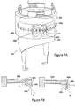
- FIGs 2 and 3 schematically show a dispenser 200 having a counter 203 and a drive mechanism 205.
- the counter comprises a second ring member 201 and a first ring member 202.
- the drive mechanism 205 is a pawl-and-teeth mechanism having a pawl-bearing member 204 (not shown in Figure 3 ) and a teeth-bearing member 206 (partially hidden from view in Figure 2 ).
- the teeth-bearing member 206 is a hollow cylinder integral with the second ring member 201.
- the pawl-bearing member extends fully around the teeth-bearing member 206.
- the reverse configuration may also be used, i.e. the pawl bearing member 206 may be integral with the second ring member 201. This arrangement is shown in Figure 7 .
- Two pawls 208 are defined by a cutaway portion of pawl-bearing member 204.
- the pawls operatively engage with a ring of teeth 210 moulded on an outwardly facing surface of the teeth-bearing member 206 by means of inwardly extending protrusions on the tips of the pawls, as will be described in more detail later.
- a pair of arms 212a, 212b extend downwardly from the pawl-bearing member on either side of the metering valve assembly.
- the arms can be spring-loaded against, or affixed to, an upper portion of a junction member (hidden from view). The junction member moves vertically when a dose is dispensed.
- the arms can be spring-loaded against, or affixed to, a moving container, e.g. a moving medicament container.
- the action of lifting the junction member 120 imparts an upward force on the pawl-bearing member 204 in a direction parallel to the vertical axis 214 of the dispenser 200. This results in frictional engagement between the pawl(s) and the teeth.
- the teeth-bearing member 206 and second ring member 201 are rotated (clockwise in this particular case) about the vertical axis 214 by an increment.
- the junction and pawl-bearing members are able to move downwards to their original positions by, for example, an internal spring (not shown) of the medicament container 114.
- This downward movement also results in frictional engagement between the pawl-bearing and teeth-bearing members, resulting in a further clockwise rotation of members 206, 201 about the vertical axis 214 by an increment.
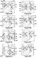
- Figure 4a illustrates a drive mechanism 205 in which the ring of teeth 210 is disposed on an inwardly facing surface of the teeth-bearing member 206, with the pawl-bearing member 204 being disposed within its bore. It will be recognised that the pawl- and teeth-bearing members are in a reverse configuration compared to the configuration shown in Figures 2 and 3 , though the operating principle of the drive mechanism remains substantially the same.
- Two pawls 402a, 402b are integrally defined in the pawl-bearing member 204, by a cutaway portion of its body. Viewed from this perspective, each pawl extends toward the ring of teeth 210 in an annular plane of the pawl-bearing member 204, at about the same (but opposite) angle ⁇ , ⁇ .
- the second (lower) pawl 402b is offset in a circumferential direction relative to the first (upper) pawl 402a.
- the pawls each have a root end and a free end. A lip 408a, 408b, protrudes radially outwardly from each of the free ends, to operatively engage with the teeth.
- valve stem 118 of the metering valve assembly inserts down through the clearance hole in the base of the pawl-bearing member 204 to rest on a shelf 410 in a stem block 412. This differs from the preferred configuration shown in Figure 1 . It will be appreciated that this difference, in itself, is not of particular significance in the context of the drive mechanism.
- the pawl-bearing member 204 moves up and down, and rotates, relative to the teeth-bearing member 206.
- the upward and downward movements of the pawl-bearing member 204 will be referred to as the 'count stroke' and 'return stroke', respectively. These terms are only used for convenience and are not to be construed as meaning that a count only occurs during the count stroke. It will be apparent to those skilled in the art (and from the following description) that a count may occur during the count stroke, return stroke or a combination of both strokes.
- Figures 5a to 5d show a sequence of cross-sectional views of the drive mechanism during the count stroke.
- the pawl-bearing member is at rest on the teeth by means of a protruding block 510.
- An upwardly directed force on the pawl-bearing member initially results in frictional engagement between the lip 408a of the first (upper) pawl 402a and a vertical face 512 of tooth 502.
- This action guides the pawl-bearing member substantially vertically upwards, until such a time as the lip 408b of the second (lower) pawl 402b engages with a lower, sloped face 514 of tooth 506 ( Figure 5b ).
- Figures 6a to 6d show a sequence of cross-sectional views of the drive mechanism during the return stroke. Like elements to those of Figure 5 are indicated by like reference numerals.
- Figure 6d corresponds substantially to Figure 5a , but rotated by one tooth, i.e. from tooth 506 to tooth 504.
- each lip comprises a driving engagement face 440, which contacts a tooth during a driving engagement of that lip 408.
- Each lip also comprises a sliding engagement face 430, which enables a lip 408 to contact and lift over a tooth without engaging the tooth.
- the large arrows denote the faces of the pawl lips that contact teeth during one of the strokes. The opposite faces (shown without arrows) contact teeth during the other stroke.
- the angle ⁇ (that is the angle of the slope of the sliding engagement face 430 of the lip with respect to a vertical axis in the figure) must be sufficiently large enough to enable the lip 408b lift away and ride over the teeth when lip 408a is engaged with a tooth (i.e. driving engagement face 440a is in contact with, and drivingly engaged with a tooth).
- An angle greater than 15° is preferred. If the angle is less than 15°, the pawl may not lift above the tooth.
- Figure 7a illustrates a preferred embodiment of the drive mechanism 205 in which the ring of teeth 210 is disposed on an outwardly facing surface of a teeth-bearing member 206, which is placed within the bore of the pawl-bearing member 204.
- each pawl comprises two arms extending toward the ring of teeth 210 in an annular plane of the pawl-bearing member 204.
- the second pawl 402b is offset in a circumferential direction relative to the first pawl 402a.
- a lip 408a, 408b protrudes radially outwardly from the point at which the two arms meet, to operatively engage with the teeth.
- Figure 7b shows a side profile of the pawls 402a, 402b.
- the numerals of figure 4b refer to like features of figure 7b .
- the angle ⁇ i.e. the angle of the sliding engagement face 430 from the vertical of the drawing
- the angle is preferably larger than 15°. More preferably, the angle is approximately 45°.
- the orientation of the first pawl 402a is reversed to that shown in figure 4b .
- the engaged pawl i.e. the pawl in driving engagement with the tooth
- the teeth-bearing member 206 moves up and down (driven by the actuation of the junction member as described above), causing the pawl-bearing member 204 to rotate relative to the teeth-bearing member 206.
- the upward and downward movements of the teeth-bearing member 206 will be referred to as the 'count stroke' and 'return stroke', respectively.
- Figures 8a to 8d show a sequence of cross-sectional views of the preferred drive mechanism during the count stroke.
- the teeth- and pawl-bearing members are at rest.
- An anti-slip bar 450 comprising a protrusion extending from the inner surface of the pawl-bearing member, is in an engaged position that is in line with the teeth to prevent non-count rotation of the pawl-bearing member (i.e. rotation of the pawl-bearing member in an opposite direction to that of the pawl-bearing member during a count).
- the ant-slip bar 450 is configured to prevent relative rotation between the teeth-bearing member and pawl-bearing member in a non-count direction by blocking motion of the pawl-bearing member.
- the bar extends sufficiently from the inner surface of the pawl-bearing to hit one of the teeth, but not the outer surface of the teeth-bearing member.
- Figures 9a to 9d show a sequence of cross-sectional views of the drive mechanism during the return stroke. Like elements to those of Figure 8 are indicated by like reference numerals.
- Face 518 proceeds further down lip 408b.
- the inner non-vertical surface of lip 408a contacts a vertical non-leading edge of a tooth, which causes the pawl 402a to lift away from the plane of the teeth, and permits the pawl 402a to ride over the tooth without engagement.
- a rotational displacement need not be performed by way of two engagements (though this may be beneficial), nor need it comprise vertical and rotational movement.
- a drive mechanism providing purely rotational motion, in other words without vertical movement, could also be used.
- FIGS 10 to 19 provide various depictions of the counter in more detail.
- the counter 203 is comprised of second ring member 201 and first ring member 202.
- the ring members are rotatably and coaxially arranged about the central axis 214, encircling the container of the dispenser.
- the first ring member is arranged substantially flush on top of the second ring member, with their outer circumferential surfaces being aligned so as to form a substantially continuous surface interrupted only by a hairline 720 where the two ring members meet.
- a pawl-bearing member 205 of a drive mechanism is integral with the second ring member 201.
- a first row of numbers 701 ('8', '9', '0', '1') is displayed on the second ring member 201, with a second row of numbers 702 ('0', '1', '2', '3', '4',) and a third row of numbers 703 ('1', '1', '1') displayed on the first ring member 202.
- a coupling mechanism 700 comprising an arm 704, a series of equally spaced protrusions 705, and a deflector 1002 can also be seen.
- the coupling mechanism allows the second ring member 201 to be coupled to the first ring member 202, so that they can be rotated in tandem by the drive mechanism when coupled, as detailed below.
- the spaced apart protrusions 705 are formed on an inner surface of the first ring member 202, and in this particular case extend only half way around the axis.
- the coupling mechanism 700 comprises four arms 704 equally spaced around the upper radial surface of the second ring member.
- the arm 704 is integrally formed with an annular band 802 that fixedly sits in a recess of an upper radial surface 804 of the second ring member 201.
- the arm 704 can be directly mounted on, or integral with, upper radial surface 804.
- the arm 704 has a slotted body 712 which extends arcuately with approximately the same curvature of second ring member 201, and an upwardly extending contact end 710.
- the first ring member 202 (shown as a shaded ring) is slidably mounted on an outer portion of the upper radial surface 804 of the second ring member (shown as a blank ring, part of which is hidden from view underneath the shaded ring). From this perspective, it is apparent that the thickness of the first ring member 202, designated 't2', is about a third of the thickness of the second ring member 201, designated 't1'.
- the thickness of the second ring member 201 may be consistent along its height or it may be tapered, it being thickest at its upper radial surface 804.
- the dashed line represents an imaginary boundary line between the arm 704 and the spaced apart protrusions 705 formed on the inner surface 902 of the first ring member 202.
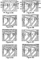
- Figures 13 and 14 show, in a series of corresponding perspective and downward views respectively, the operation of the coupling mechanism.
- Figures 13a and 14a show the arm 704 at a distance from the deflector 1002.
- the second ring member 201 and arm 704 are rotated in an anticlockwise direction, so that the upwardly extending contact end 710 of the arm 704 approaches the deflector 1002.
- the deflector 1002 is fixed to the container, or alternatively to an upper portion of a housing of the dispenser and/or to a sleeve surrounding the container. The deflector extends downwardly only to such an extent that the body 712 of the arm is allowed to pass underneath unimpeded.
- the arm 704 is deflected outwards ( Figures 13c and 14c ). At this point a trailing end 718 of the slot 714 catches one of the teeth 1102, thereby causing the first ring member 202 to be pulled along.
- the tooth 1102 is released by the trailing end of the slot and the arm returns to its non-flexed position ( Figures 13d and 14d ).
- the upwardly extending contact end 710 of the arm 704 may have a face 720 complementing the inclined face 1004 of the deflector 1002, to allow for a smooth deflection.
- the contact end 710 is pointed so that when it reaches the apex of deflector 1002, the arm can immediately begin to return to its non-flexed position.
- the slot 714 forms an engaging portion of the arm 704, but it is recognized that any suitable engaging means could be used such as a hook. Accordingly, recesses could be formed in the first ring member instead of protrusions.
- the arm 704 is sufficiently flexible to permit a radially outward deflection (that is, towards the protrusions) when encouraged to do so, but also resilient enough to return to its original position.
- the counter may additionally comprise a second deflector that functions to move or deflect the engagement means (e.g. arm 704) back to its non-flexed position.
- This second deflector may, for example, be fixed to, or integral with, an inner surface of the first ring member 202.
- the first ring member is preferably slidably mounted on the second ring member so as to resist rotation when there is no engagement between the arm and the teeth.
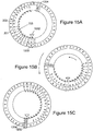
- FIG. 15a to 15c show the second and first ring members in three different display positions.
- the ring members 201, 202 are shown as flat rings.
- the second ring member 201 has a first row of numbers comprising four repeated sets of consecutive integers '0' to '9', i.e.: 01234567890123456789012345678901234567890123456789.
- Each set of integers covers a quarter turn of the second ring member 201, and here represents the 'units' digits of a count.
- the first ring member 202 has second and a third rows of numbers.
- the second row comprises two repeated sets of consecutive integers '1' to '9' separated by a '0', while the third row comprises ten '1's optionally followed by a '2', e.g..:
- each set of integers of the second and third rows covers a quarter turn of the first ring member 202.
- the second row represents 'tens' digits
- the third row represent 'hundreds' digits of a count.
- Also shown on the first ring is a warning symbol in the form of an exclamation mark '!'.
- the second ring member For each of the first nine dispensed doses, the second ring member is rotated anticlockwise by an increment, i.e. counting down from '9' to '0', until the number '190' is displayed. Then for the tenth dispensed dose, the second and first ring members are coupled by means of the coupling mechanism so that the ring members are rotated in tandem by an increment. This results in the number '189' being displayed through window 1202. For the subsequent nine dispensed doses, the second ring member is again rotated anticlockwise by increments until the number '180' is displayed. For the twentieth dispensed dose, the coupling mechanism is again engaged, so that the second and first ring members are rotated in tandem by an increment and the number '179' is displayed through the window 1202.
- Figure 15b shows an intermediate count position, in which the number '72' is displayed. In this position, the third row has run out and a blank space appears instead.
- the blank space may be filled with indicia other than numbers, such as colours.
- the second row of numbers can be replaced by an exclamation marks '!' or other warning indicators.
- Preferred warning indicators for this purpose are colours (e.g. red).
- the protrusions are equally spaced apart. Particularly preferably the protrusions only extend three quarters of the way (e.g. about 270°) around the ring member, still more preferably the protrusions only extend between a quarter and half way (e.g. about 90°, 108° or 180°, or any angle therebetween) around the ring member.
- the counter will have two arms spaced at 180 degree intervals.
- Figures 16 and 17 are perspective views of a dispenser including the counter. In contrast to Figures 2 and 3 , the pawl-bearing member rather than the teeth-bearing member is integral with the second ring member 201. Also visible in Figure 16 is a strip of colour following the third row of numbers 703. Figure 17 shows how a count ('119') can be viewed through a window 1202 of a housing 1402 of the dispenser.
- Figures 18a to 18c show part of the counter described in WO2010/103315 .
- the first ring member 1510 is rotatably and coaxially arranged with a second ring member 201 about a central axis 214 as described above (and as shown in figures 10 and 11 ).
- WO2010/103315 describes ring member 1510 as its second ring member but we have amended the terminology to be consistent with the language used herein. For clarity, the second ring member 201 is not shown in these drawings.
- the first ring member is arranged substantially flush on top of the second ring member, with their outer circumferential surfaces being aligned so as to form a substantially continuous surface interrupted only by a hairline where the two ring members meet.
- a pawl-bearing member 205 of a drive mechanism is integral with the second ring member 201.
- the counter further comprises a third ring member 1502 that is coaxially arranged with the first ring member 1510.
- the third ring member comprises a deflector 1504 to deflect arm 704 on the second ring member 201 to engage with protrusions 1516 on the inside surface of the first ring member 1510 in the manner as described above with reference to figures 13 and 14 .
- the third ring member has a gap 1518 in its outer wall to enable the arm 704 to deflect outwards.
- a sloped edge on the trailing boundary of the window 1518 engages with an edge of the arm 704 to push the arm 704 away from the teeth 1516 after the arm has engaged with the teeth 1516. This ensures that unwanted further engagement of the tens (second) ring (which would lead to an incorrect dosage value being displayed) does not happen.
- the third ring member 1502 further comprises a limiting mechanism 1506 which comprises a flexible and resiliently deformable portion that applies pressure to an upper circumferential surface of the first ring member 1510.
- the limiting mechanism limits the amount of rotation of the first ring member relative to the third ring member. More specifically, the limiting mechanism prevents the first ring member incorrectly rotating by two protrusions (or counts) in the event that the arm fails to decouple properly.
- the first ring member 1510 also comprises a plurality of protrusions 1512 on an upper circumferential surface to engage with the limiting mechanism 1506 of the third ring member 1502.
- protrusions 1512 are substantially equally-spaced. More preferably, the protrusions 1512 have substantially the same spacing as protrusions 1516 on the inside surface of the first ring member.
- the first ring member rotates at the same rate as the second ring member (until the second and first ring members become uncoupled).
- the protrusions 1512 are spaced at substantially the same distance as protrusions 1516 (which form part of the coupling mechanism between the second and first ring members), this prevents the first ring member rotating further than is desired even if the arm does not properly decouple, which would indicate an incorrect count.
- the third ring member also comprises a plurality of locating recesses 1508a, 1508b and 1508c in the upper circumferential surface.
- correspondingly-shaped protrusions locate within these recesses to hold the third ring member in place and therefore to prevent rotation of the third ring member.
- the protrusions may be located in a container or a dispenser (e.g. in a dispenser cap). By preventing the third ring member from rotation, this ensures that the deflector 1504 remains in a consistent position relative to the second and first ring members.
- a plurality of corresponding-shaped protrusions located in a container or dispenser may be designed with an asymmetrical pattern to provide a keying function. That is, the third ring member will only locate in one rotational position relative to the container and dispenser, and therefore also the second and first ring members. This ensures that the third ring member is always located correctly with respect to the second and first ring members to allow the count to correctly register.
- the first ring member 1510 further comprises a display cover element 1514 for obscuring a view of the first indicia (as described above with reference to figure 15 ) to indicate that the counter has reached zero, indicating an empty dispenser.
- Figures 19a and 19b show the third ring member without the first ring member.
- the reference numerals correspond with those in figure 18 .
- the limiting mechanism 1506 described above with reference to the third ring member 1502 does not always reliably prevent over- or back-rotation of the first ring member. It is noted that the limiting mechanism 1506 acts in the vertical direction (i.e. a direction parallel to the longitudinal axis of the dispenser and counter rings), that is the flexible and resilient portion of the limiting mechanism 1506 applies pressure in the vertical direction and is deformed in the vertical direction to act as a limiting mechanism.
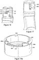
- figures 20a to 20d are perspective views of a limiting ring member according to the present invention
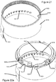
- figure 21 is a perspective view of a counter ring member (for example a first ring member) adapted to work with the limiting ring member of figures 20a to 20d
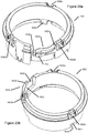
- figures 22a to 22c are perspective views of the limiting ring member of figures 20a to 20d coupled with the counter ring member of figure 21 .
- the first ring member 1610 is rotatably and coaxially arranged with a second ring member 201 about a central axis 214 as described above (and as shown in figures 10 and 11 ).
- the second ring member 201 is not shown in these drawings.
- the first ring member is arranged substantially flush on top of the second ring member, with their outer circumferential surfaces being aligned so as to form a substantially continuous surface interrupted only by a hairline where the two ring members meet.
- a pawl-bearing member 205 of a drive mechanism is integral with the second ring member 201.
- the counter further comprises a limiting ring member 1602 that is coaxially arranged with the first ring member 1610.
- the limiting ring member 1602 sits atop the first ring member 1610, with edge 1650 on the limiting ring member 1602 contacting and resting on the edge 1652 of the first ring member 1610.
- the limiting ring member 1602 does not rotate.
- the limiting ring member comprises a deflector 1604 to deflect arm 704 on the second ring member 201 to engage with protrusions 1616 on the inside surface of the first ring member 1610 in the manner as described above with reference to figures 13 and 14 .
- the limiting ring member has a gap 1618 in its outer wall to enable the arm 704 to deflect outwards.
- a sloped edge on the trailing boundary of the window 1618 engages with an edge of the arm 704 to push the arm 704 away from the teeth 1616 after the arm has engaged with the teeth 1616. This ensures that unwanted further engagement of the tens (first) ring member (which would lead to an incorrect dosage value being displayed) does not happen.
- the limiting ring member 1602 further comprises a limiting mechanism 1606 which comprises an engaging portion 1620 arranged to act radially (inwardly and/or outwardly) with respect to the first ring member 1610 to contact the first ring member to limit free rotation of the first ring member relative to the limiting member about the coaxial axis.
- the engaging portion 1620 is preferably a tooth.
- the purpose of the limiting mechanism is to prevent free rotation of the first ring member. That is, to prevent over-rotation of the first ring member when the first ring member is driven to register a count. Over-rotation of the first ring member during a count leads to an incorrect dosage value being displayed.
- the limiting mechanism may also be configured to limit free rotation in a reverse count direction, again to prevent an incorrect dosage value being displayed. Preferably the limiting mechanism not only limits free rotation in the reverse count direction, but also prevents any rotation in the reverse count direction.
- the engaging portion 1620 is preferably located on a base or panel 1622.
- One end of the panel 1622 is fixed to the limiting ring member 1602 at location 1626.
- the other end of the panel 1622 comprises a floating end.
- the panel is flexibly fixed at location 1626 to the limiting ring member 1602 such that the floating end of the panel may swing radially with respect to the first ring member.
- the floating end is moveable radially inwardly and outwardly with respect to the first ring member.
- the engaging portion 1620 is located at the floating end of the panel.
- radial movement of the floating end enables the engaging portion to come into contact with a surface of the first ring member.
- the engaging portion 1620 may be configured to contact an inner or outer surface of the first ring member 1610.
- the engaging portion 1620 contacts an inner surface of the first ring member 1610.
- the inner surface of the first ring member 1610 is preferably also provided with an engaging portion 1630, which preferably comprises a plurality of teeth that are shaped to co-operate with the engaging portion 1620 of the limiting mechanism.
- the engaging portion teeth 1630 are preferably ratchet teeth or teeth in the shape of a saw-tooth formation.
- engaging portion 1620 rests between neighbouring teeth 1630 of the first ring member 1610.
- engaging portion 1620 rides up the surface of a tooth 1630. As it does so, the base 1622 flexes at point 1626 to accommodate the height of the tooth until engaging portion 1620 falls between the next pair of neighbouring teeth 1630 on the first ring member.
- a rotation of the second ring member 201 driven by the drive mechanism, can only cause the first ring member 1610 to rotate by one increment.
- the teeth 1630 are ratchet teeth or saw-tooth shaped-teeth, the angle of the slope on surface of the tooth 1630 in the reverse count direction is greater than the angle of the surface of the tooth 1630 in the forward count direction. As such, the steeper slope of the tooth 1630 abuts the engaging portion 1620 to prevent rotation of the first ring member in the reverse count direction.
- the pitch between teeth 1630 is half of the pitch between protrusions 1616 in the coupling mechanism between the second and first ring members. As such, for every protrusion 1616, the engaging portion 1620 moves two teeth 1630 forward.
- the pitch between teeth 1630 could be more or less than half of the pitch between protrusions 1616.
- the pitch between teeth 1630 could be 1:1, or it could be even smaller, such as 1/3, 1/4, 1/5.
- the limiting mechanism 1606 also comprises a guide in the form of an arm 1624, which projects from the base or panel 1622.
- the purpose of the arm 1624 is to keep the engaging portion 1620 in contact with the engaging portion teeth 1630 on the first ring member 1610.
- the arm 1624 is arranged in a fixed relation to the engaging portion 1620 (i.e. it remains a fixed distance apart), and the arm contacts on the opposite surface of the first ring member 1610 to the engaging portion teeth 1630.
- the arm 1624 therefore contacts the outer surface of the first ring member 1610. When in position, the first ring member therefore sits between the arm 1624 and the engaging portion 1620, as shown in figures 22a to 22c .
- a limiting mechanism 1606 that acts radially with respect to the first ring member, this alleviates the problems with manufacturing tolerances in the vertical direction that were associated with the prior version of the limiting mechanism 1506. Instead of all of the manufacturing tolerances stacking up in the vertical direction, the only manufacturing tolerances that influence the operation of the improved limiting mechanism 1606 are those associated with the manufacturing of the limiting mechanism 1606 itself, and the radial dimensions of the first ring member 1610. As such, more reliable operation of the limiting mechanism is experienced.
- the engaging portion 1620 may more reliably track the first ring member, to ensure that the engaging portion 1620 remains in contact with the engaging portion teeth 1630 on the first ring member 1610.
- movement of the first ring member 1610 in the radial direction should not cause the engaging portion 1620 to disengage with the teeth 1630, since the arm 1624 will follow the movement of the first ring member or any contours that the first ring member may have (since it is in contact with the first ring member) when the first ring member moves radially outwards, and the engaging portion 1620 will follow movement of the first ring member when the first ring member moves radially inwardly.
- the limiting ring member also comprises a plurality of locating recesses 1608a, 1608b and 1608c in the upper circumferential surface. Correspondingly-shaped protrusions locate within these recesses to hold the limiting ring member in place and therefore to prevent rotation of the limiting ring member.
- the protrusions may be located in a container or a dispenser (e.g. in a dispenser cap). By preventing the limiting ring member from rotation, this ensures that the deflector 1604 remains in a consistent position relative to the second and first ring members.
- a plurality of corresponding-shaped protrusions located in a container or dispenser may be designed with an asymmetrical pattern to provide a keying function. That is, the limiting ring member will only locate in one rotational position relative to the container and dispenser, and therefore also the second and first ring members. This ensures that the limiting ring member is always located correctly with respect to the second and first ring members to allow the count to correctly register.
- the first ring member 1610 may also comprises a display cover element 1614 for obscuring a view of the first indicia (as described above with reference to figure 15 ) to indicate that the counter has reached zero, indicating an empty dispenser.
- the limiting mechanism 1606 has been described with reference to a two-ring counter mechanism (i.e. second, unit, ring member and first, tens, unit ring member), the limiting mechanism may instead be used with a single ring member counter mechanism (i.e. using only the second, units, ring).
- the second ring member would comprise the pawl mechanism as described above, but would not comprise the coupling arms 704.
- the limiting mechanism may also be used in a counter mechanism having more than two ring members, for example a three or four-ring counter mechanism.
- a limiting mechanism may be provided that protrudes from a dispenser cap or canister within the dispenser i.e. that does not comprise a limiting ring member arranged co-axially with the first ring member.
- the limiting mechanism 1606 must remain in fixed relation to the first ring member.
- the alternative limiting mechanism also acts radially, and would comprise the engaging portion 1620 disposed on a base with a floating and fixed end, and having a guide arm as arranged above.
- the deflector 1604 also would need to be arranged to protrude from the canister or dispense or dispenser cap and remain in a fixed position relative to the first ring member.
Description
- This invention generally relates to counters and in particular to counters for use with dispensers and to dispensers comprising said counters. More particularly the present invention relates to counters for use with metered-dose dispensers, such as metered-dose inhalers (MDls).
- Counters are useful in a wide variety of applications, and are especially important in the field of medical dispensers where an accurate determination of the number of doses of medicament remaining in a medicament container might otherwise be difficult to obtain. An example of such a medical dispenser is a metered-dose inhaler.
- Metered-dose inhalers (MDIs) are devices for dispensing medicaments, e.g. in aerosol form, to the lungs. Broadly speaking dispensers such as MDIs are comprised of two components: a container and a delivery device. The container holds the medication, e.g. dissolved or suspended in a propellant under high pressure to maintain a liquid phase. Additionally the container often comprises an internal metering valve, which is designed to release a precisely measured, reproducible dose of medicament when the valve is actuated. The delivery device typically includes an actuator and a mouthpiece. The actuator, which can be triggered by the user, for example by inhalation or manual operation, typically interacts with the metering valve of the container to induce release of a dose. The mouthpiece serves to direct the medication towards the user.
Figure 1 provides a view of a breath actuated dispenser and will be discussed in more detail below. - As medicament containers are typically made of an opaque material such as aluminium, and may be housed entirely within a delivery device, it is generally not possible for a user to gauge effectively how many doses of medicament remain therein. This may result in a user prematurely discarding a MDI still containing doses of medicament or worse using the MDI beyond its recommended lifetime. Neither situation is desirable - the former is wasteful while the latter is potentially dangerous. Users sometimes shake MDIs to try to obtain a measure of whether any medicament is present therein, but this only provides a very crude qualitative measure of the container contents. It would not, for example, enable a user to distinguish between a container comprising enough medicament and propellant to form a dose and one comprising a quantity of medicament and propellant that is less than that needed to fill the metering valve. In other words, there is a risk that users overestimate the amount of medicament present in a container and mistakenly conclude that there is sufficient medicament remaining for another dose when in fact there is not. Additionally a user may not be provided with sufficient warning to obtain a replacement medicament container prior to the one in use running out.
- It is therefore desirable to provide dispensers, e.g. inhalers, with a counter mechanism that enables a user to track how many doses have been dispensed therefrom and, complementarily, how many doses remain. Indeed, regulatory bodies such as the Food and Drug Administration (FDA) of the United States and the European Medicines Agency (EMEA) have issued guidelines encouraging the implementation of dose-counters (Food and Drug Administration, "Guidance for industry: integration of dose counting mechanisms into MDI drug products", 2003; European Agency for Evaluation of Medicinal Products, "Final guideline on the quality of inhalation and nasal products", 2005).
- Dose counters can generally be classified according to the manner by which a 'count' is registered, these being mechanical counters comprised of a series of moving parts that respond to a movement or mechanical force resulting, for example, in a displacement of the container/housing; electronic counters having electrical circuitry to sense an event associated with an actuation such as sound, temperature or pressure change; and electro-mechanical counters which combine electrical and mechanical parts.
- Some background prior art relating to dose counters includes:
EP1169245 Dispensing Apparatus Comprising a Dosage Counting Device;PCT/GB97/03480 PCT/US1996/008418 Indicator Device Responsive to Axial Force;PCT/FR2004/001844 GB2372542 PCT/CA04/001884 PCT/US04/039926 Dose Counter for Dispensers; andUS7047964 Dispenser for Medicament. - Other developments in the field of dose counters include Bang & Olufsen Medicom's 'Insulair' (Trade Mark) device, and the disclosures of:
WO 98/056444 WO 04/001664 WO 07/012854 DE 10061723 Zählwerk zum Zahlen dosierter Abgaben flussiger oder fester Produkte sowie Einrichtung zum dosierten Abgeben solcher Produkte. -
EP-A-2196234 discloses a metered dose inhaler including a dose counter. We have also previously described a dispenser and counter inWO2010/103315 . - Although such devices have provided the advantage of being able to provide some measure of the number of doses of medicament dispensed from a container and/or the number of doses remaining therein, there remains room for improvement. In particular it has proven difficult to provide dose counters that reliably "count" the release of medicament doses from containers. The difficulty encountered is that a relatively small movement, typically of the metering valve stem, needs to be detected and translated into a count. This difficulty is exacerbated by manufacturing tolerances in the length of medicament containers which means they do not have a consistent length, and also manufacturing tolerances in the dimensions of the components comprising the counter mechanism and its coupling to the dispenser mechanism. At the same time, it is highly undesirable for any movements to not be counted since this will lead to the counter indicating a higher number of doses remaining than is actually the case. Moreover there is also regulatory pressure to minimise the number of false counts.
- According to the present invention, there is provided a counter comprising: a first ring member having a first indicia and being rotatable in increments about an axis, the first indicia indicating a count; a limiting member comprising a limiting mechanism, wherein the limiting mechanism comprises an engaging portion arranged to act radially with respect to the first ring member to contact the first ring member to limit free rotation of the first ring member relative to the limiting member about the axis; and
- a guide, the guide comprising an arm spaced apart from the limiting member engaging portion in a fixed relation, the guide being configured to contact the first ring member such that the limiting member engaging portion maintains contact with the first ring member.
- By providing a limiting mechanism that acts radially on the first ring member, this alleviates the problems associated with manufacturing tolerances in the vertical direction (which is perpendicular to the radial direction acting on the first ring member). Tolerances in the vertical dimension have little effect on the action of the limiting mechanism acting radially with respect to the first ring member. As such, more reliable operation of the limiting mechanism is enabled.
- The engaging portion may comprise one or more teeth arranged to contact an inner circumferential surface of the first ring member. Alternatively, the engaging portion may be arranged to contact an outer circumferential surface of the first ring member.
- The first ring member may comprise an engaging portion arranged to co-operate with the engaging portion of the limiting member to limit free rotation of the first ring member relative to the limiting member about the axis. The engaging portion on the first ring member preferably comprises a plurality of teeth on an inner circumferential surface of the first ring member. Alternatively, the plurality of teeth may be located on an outer circumferential surface of the first ring member. The plurality of teeth on the inner or outer circumferential surface of the first ring may comprise ratchet teeth. By providing ratchet teeth, this enables limited rotation in one direction (preferably the count direction) and enables rotation in a reverse count direction to be prevented.
- The one or more teeth of the limiting member engaging portion may comprise one or more triangular or ratchet-shaped teeth. This enables the engaging portion to interact with the engaging portion on the first ring member to limit its free rotation.
- The limiting mechanism comprises a guide comprising an arm. By providing the guide arm at a fixed distance from the engaging portion that may move radially, the engaging portion may more reliably track the first ring member, to ensure that the engaging portion remains in contact with the engaging portion on the first ring member. That is, movement of the first ring member in the radial direction (for example if there is some radial play between the first ring member and the limiting ring
member) should not cause the engaging portion to disengage with the engaging portion on the first ring member, since the arm will follow the movement of the first ring member or any contours that the first ring member may have (since it is in contact with the first ring member) when the first ring member moves radially outwards, and the engaging portion will follow movement of the first ring member when the first ring member moves radially inwardly. - Preferably, the guide contacts the first ring member on an outer circumferential surface. In embodiments where the engaging portion on the first ring member is on the outer circumferential surface of the first ring member, the guide acts on the inner circumferential surface.
- The limiting mechanism may also be supported on a base having a fixed end and a floating end, the fixed end being coupled to the limiting member and the floating end being free of the limiting member, and wherein the base being flexible at the fixed end such that the floating end is moveable radially with respect to the first ring member. Preferably, the limiting member engaging portion is located at the floating end of the base. The engaging portion may therefore move radially inwardly and outwardly with respect to the first ring member.
- The limiting member may also comprise a limiting ring member coaxially arranged about the same axis as the first ring member.
- When the limiting mechanism comprises a limiting ring member, the limiting ring member may comprise one or more locating recesses disposed in an upper circumferential surface for engaging with correspondingly-shaped protrusions in a housing for preventing rotation of the limiting ring member about the axis. Such an arrangement enables to the limiting mechanism to remain in a fixed relation to the first ring member.
- In any of the above described limiting mechanisms, the limiting mechanism may be configured to provide a frictional resistance to the first ring member in a forward count direction of the first ring member, and to prevent movement of the first ring member in a reverse count direction. As such, this arrangement provides protection against over-counting in a forward count direction, and prevents rotation of the counter in a reverse count direction.
- The counter may also comprise: a second ring member having second indicia, the second ring member being rotatable in increments about the same axis as the first ring member, the second indicia indicating a count; a coupling mechanism for releasably coupling the second ring member to the first ring member, to allow the second and first ring members to rotate cooperatively when coupled and to allow independent rotating of the second ring member when not coupled; wherein the coupling mechanism comprises first and second engagement means, the first engagement means being movable radially outwardly and radially inwardly relative to the axis.
- A second ring member arranged co-axially with the first ring member provides a counter having a number of indicia marked thereon to enable a greater number of counts to be registered. For example, the first indicia may display tens and hundred units, and the second indicia may display units.
- In embodiments having a second ring member, the coupling mechanism comprises a deflector to deflect the first engagement means radially outwardly. Preferably, the first engagement means is deflected radially outwardly after a predetermined degree of rotation of the second ring member, the predetermined amount of rotation of the second ring member being less than a full rotation of the second ring member about the axis. The deflector may be connected to, or integral with the limiting member.
- The first engagement means may be connected to, or integral with, the second ring member. The first engagement means may also comprise an arm having a slot and a contact end, preferably the first engagement means comprises four arms each having a slot and a contact end. The contact end may comprise an upwardly extending component that contacts the deflector.
- In embodiments having a second ring member, the second engagement means may be connected to, or integral with, the first ring member. Furthermore, the second engagement means may comprise a plurality of protrusions, which may be equally spaced apart from one another.
- The first engagement means may be moved radially outwardly. When moved radially outwardly, the first engagement means engages with one of the protrusions. When engaged, the first ring member overcomes frictional resistance of the limiting mechanism in a forward count direction and the first ring member rotates in the forward count direction.
- The first ring member comprises a display cover element for obscuring a view of the second indicia on the second ring member. The enables the user to be informed that the doses left in a medicament container have expired.
- The counter may also comprise a drive mechanism for rotating the second ring member, and wherein at least part of the drive mechanism is integral with the second ring member. Preferably, the drive mechanism comprises a pawl-and-teeth mechanism.
- In such embodiments with a pawl-and-teeth mechanism, the pawl-and-teeth mechanism may comprise: a first and second pawl engageable with a plurality of teeth, and wherein each of the first and second pawls comprise a driving engagement face for engaging in a driving engagement with one of the plurality of teeth, and a sliding engagement face for sliding over one of the plurality of teeth.
- Each of the first and second pawls may be arranged such that: the first pawl engages in a driving engagement with one of the plurality of teeth during a count stroke of the drive mechanism, and the second pawl engages in a driving engagement with one of the plurality of teeth during a return stroke of the drive mechanism.
- Furthermore, each of the first and second pawls may be arranged such that: the second pawl rides over one of the plurality of teeth during a count stroke of the drive mechanism, and the first pawl rides over one of the plurality of teeth during the return stroke of the drive mechanism.
- In some embodiments, the first and second pawls are integral with the second ring member, and the plurality of teeth are disposed on a teeth-bearing member arranged to be reciprocally moveable within a bore of the second ring member, and wherein the pawl-and-teeth mechanism is configured such that reciprocal movement of the teeth-bearing member within the bore of the second ring member causes rotational movement of the second ring member.
- When coupled to a dispenser having a body for receiving a medicament container and a dispensing mechanism for dispensing a dose of medicament from the container, the rotating of the second ring member of the counter occurs in response to the dispenser being actuated. The count may be indicative of doses of medicament dispensed from, or remaining in, the container.
- The first indicia may comprise one or more of: numbers, colours, letters and symbols. Furthermore, the second indicia may also comprise one or more of: numbers, colours, letters and symbols.
- The second indicia may also comprise a first row of numbers, and said first indicia comprise a second and a third row of numbers. In such embodiments, the first row of numbers represents units digits, said second row represents tens digits, and said third row represents hundreds digits. The first row of numbers may comprise repeated sets of integers.
- Furthermore, the second row of numbers may comprise repeated sets of integers and the third row of numbers may comprise a set of integers.
- The first and second indicia may be printed, cut out from, embossed, moulded, adhered, incorporated, and/or painted on said first and second ring members.
- The present invention also provides a dispenser comprising the counter as described a above.
- A dispenser may comprise: a body for receiving a medicament container; a medicament container; a dispensing mechanism for dispensing a dose of medicament from the container; and the counter as described above.
- In such dispensers, the dispenser may be a pressurised metered-dose inhaler (pMDI). Furthermore, the dispensing mechanism for dispensing a dose of medicament from the container may be breath-actuated.
- These and other aspects of the invention will now be further described, by way of example only, with reference to the accompanying figures in which:
-
Figure 1 is a cross-sectional view of a dispenser to which a counter according to the present invention may be attached; -
Figure 2 is a perspective view of a dispenser (with parts removed for illustration purposes) including a counter according to the present invention; -
Figure 3 is a perspective view of a dispenser (with parts removed for illustration purposes) including a counter according to the present invention; -
Figures 4a and 4b show a drive mechanism for a counter according to the present invention; -
Figures 5a to 5d are schematic diagrams showing a part of the principle of operation of the drive mechanism of a counter according to the present invention; -
Figures 6a to 6d are schematic diagrams showing another part of the principle of operation of the drive mechanism of a counter according to the present invention; -
Figures 7a and 7b show a preferred drive mechanism for a counter according to the present invention; -
Figures 8a to 8d are schematic diagrams showing a part of the principle of operation of the preferred drive mechanism of a counter according to the present invention; -
Figures 9a to 9d are schematic diagrams showing a part of the principle of operation of the preferred drive mechanism of a counter according to the present invention; -
Figure 10 is a perspective view of a counter according to the present invention; -
Figure 11 is a perspective view of a second ring member of the counter ofFigure 10 ; -
Figure 12 is a top view of the counter ofFigure 10 ; -
Figures 13a to 13d schematically show in perspective view the operating principle of a counter according to the present invention; -
Figures 14a to 14d schematically show from a top view the operating principle of a counter according to the present invention; -
Figures 15a to 15c are schematic diagrams showing the principle of operation of a counter according to the present; -
Figure 16 is a perspective view of a dispenser including a counter according to the present invention; -
Figure 17 is a perspective view of a dispenser including a counter according to the present invention; -
Figures 18a to 18c are perspective views of portions of a counter; -
Figures 19a to 19b are perspective views of a third ring member offigure 18 ; -
Figures 20a to 20d are perspective views of a limiting ring member according to the present invention; -
Figure 21 is a perspective view of a counter ring member adapted to work with the limiting ring member offigures 20a to 20d ; and -
Figures 22a to 22c are perspective views of the limiting ring member offigures 20a to 20d coupled with the counter ring member offigure 21 . - To explain the invention, a brief overview of some features and operating principles of exemplary dispensers is initially provided. As used herein the term "dispenser" is intended to mean any device having a body suitable to receive a container holding a product and which has a mechanism to dispense the product from the container upon actuation.
-
Figure 1 shows in partial cross section an example of a breath-actuated, kink valve dispenser. Thedispenser 100 comprises abody 102 with amouthpiece 104 and apivotable mouthpiece cover 106. The mouthpiece cover is pivotable about an axis, A, low in the body and carried on a cam arrangement comprising two cam lobes (only onecam lobe 108 is shown), together with acentral finger 110. The body has anopening 112 for receiving amedicament container 114. The container may be held fixedly in place at the upper end of the body, at a location where the body extends completely around a metering valve assembly of the container (not shown). The metering valve assembly comprises ametering chamber 116 and anoutlet stem 118. Alternatively, or additionally, if the container is housed entirely within the dispenser, the container may be held at an end distal of its metering valve assembly, for example by a cap portion of an outer housing. - Moulded inside the body, inwards of the
opening 112 are internal grooves (not shown). Ajunction member 120 is slidably accommodated in the body with the grooves engaged by ribs in its periphery. The junction member has a pair of pivot clips (not shown) for pivotally locating theflap 122 in thejunction member 120. Centrally, the junction member has asocket 124 for theoutlet stem 118 of the metering valve assembly. The socket is continued by apassage 126, which has a thin wall, kinkable portion and a nozzle end. The nozzle end is in a movable part of the junction member. The main part and the movable part of the junction member are connected by a living hinge. - The moving part of the
junction member 120 also carries a pair of sears (not shown) that are arranged to engage with latches on the underside offlap 122 as described below. The movable part of the junction member also carries a finger for engagement with the cam arrangement. - Initially when the dispenser is closed the flap is unlatched and the movable part of the junction member is in its lower position. The kinkable portion, sometimes called a kinkable valve, is open. On opening of the
mouthpiece cover 106, the central finger of the cam arrangement acts on the movable part of the junction member to close the kink valve. The movement of the movable part of the junction member also serves to engage the sears of the movable member with the latches of the flap, thereby fixing the flap in an upper position. Thejunction member 120 is also lifted by themain cam lobes 108 against an internal spring (not shown) of the metering valve assembly, with displacement of thestem 118 inwards of the container. Further lifting of themouthpiece cover 106 opens the container valve and a metered dose is released into the upper part of the tube, the dose being retained by the closed kink valve acting as a closed valve. - Breathing in through the mouthpiece causes an air flow through the dispenser and impinges on
flap 122. This causes release of the sears and the kink tube tends to straighten under the action of its own resilience and the pressure of the retained dose. The dose is thus released through the nozzle into the mouthpiece for inhalation. The flap may also carry a finger (not shown) that can act on the moveable part of the junction member to ensure that the kink valve is opened when the flap is breath actuated. - These and other features of exemplary dispensers are described in more detail in Clinical Designs Limited's prior
PCT applications WO 1998/41254 US 6422234 );WO 2002/11802 US 7036505 );WO 2002/058772 US 6866038 ) and especiallyWO 2004/073776 US 2007 062522 ). - The term "drive mechanism" is to be interpreted broadly as any means by which the dispensing of a dose from the medicament container is linked to a count being made by the counter. In described embodiments the dispensing of a dose will involve a vertical movement, e.g. of
junction member 120, as described earlier with reference toFigure 1 . In the described preferred embodiment, this vertical movement is translated into an incremental rotation that is counted. In other embodiments the vertical movement that is translated into an incremental rotation may be the movement of a medicament container. -
Figures 2 and 3 schematically show adispenser 200 having acounter 203 and adrive mechanism 205. The counter comprises asecond ring member 201 and afirst ring member 202. Thedrive mechanism 205 is a pawl-and-teeth mechanism having a pawl-bearing member 204 (not shown inFigure 3 ) and a teeth-bearing member 206 (partially hidden from view inFigure 2 ). In this particular embodiment, the teeth-bearingmember 206 is a hollow cylinder integral with thesecond ring member 201. The pawl-bearing member extends fully around the teeth-bearingmember 206. The reverse configuration may also be used, i.e. thepawl bearing member 206 may be integral with thesecond ring member 201. This arrangement is shown inFigure 7 . - Two
pawls 208 are defined by a cutaway portion of pawl-bearingmember 204. The pawls operatively engage with a ring ofteeth 210 moulded on an outwardly facing surface of the teeth-bearingmember 206 by means of inwardly extending protrusions on the tips of the pawls, as will be described in more detail later. A pair ofarms - The action of lifting the junction member 120 (which causes the release of a dose from a pressurised medicament container 114) imparts an upward force on the pawl-bearing
member 204 in a direction parallel to thevertical axis 214 of thedispenser 200. This results in frictional engagement between the pawl(s) and the teeth. In turn, the teeth-bearingmember 206 andsecond ring member 201 are rotated (clockwise in this particular case) about thevertical axis 214 by an increment. - Once a dose is released and the mouthpiece cover is being closed or is closed, the junction and pawl-bearing members are able to move downwards to their original positions by, for example, an internal spring (not shown) of the
medicament container 114. This downward movement also results in frictional engagement between the pawl-bearing and teeth-bearing members, resulting in a further clockwise rotation ofmembers vertical axis 214 by an increment. - Taken together, these two increments of rotation define a "complete" incremental rotation of the second ring-
like member 201 from a first to a second position. -
Figure 4a illustrates adrive mechanism 205 in which the ring ofteeth 210 is disposed on an inwardly facing surface of the teeth-bearingmember 206, with the pawl-bearingmember 204 being disposed within its bore. It will be recognised that the pawl- and teeth-bearing members are in a reverse configuration compared to the configuration shown inFigures 2 and 3 , though the operating principle of the drive mechanism remains substantially the same. - Two
pawls member 204, by a cutaway portion of its body. Viewed from this perspective, each pawl extends toward the ring ofteeth 210 in an annular plane of the pawl-bearingmember 204, at about the same (but opposite) angle α, β. The second (lower)pawl 402b is offset in a circumferential direction relative to the first (upper)pawl 402a. The pawls each have a root end and a free end. Alip - The valve stem 118 of the metering valve assembly inserts down through the clearance hole in the base of the pawl-bearing
member 204 to rest on ashelf 410 in astem block 412. This differs from the preferred configuration shown inFigure 1 . It will be appreciated that this difference, in itself, is not of particular significance in the context of the drive mechanism. - In operation, and viewed from this perspective, the pawl-bearing
member 204 moves up and down, and rotates, relative to the teeth-bearingmember 206. For convenience, the upward and downward movements of the pawl-bearingmember 204 will be referred to as the 'count stroke' and 'return stroke', respectively. These terms are only used for convenience and are not to be construed as meaning that a count only occurs during the count stroke. It will be apparent to those skilled in the art (and from the following description) that a count may occur during the count stroke, return stroke or a combination of both strokes. -
Figures 5a to 5d show a sequence of cross-sectional views of the drive mechanism during the count stroke. InFigure 5a , the pawl-bearing member is at rest on the teeth by means of aprotruding block 510. An upwardly directed force on the pawl-bearing member initially results in frictional engagement between thelip 408a of the first (upper)pawl 402a and avertical face 512 oftooth 502. This action guides the pawl-bearing member substantially vertically upwards, until such a time as thelip 408b of the second (lower)pawl 402b engages with a lower, slopedface 514 of tooth 506 (Figure 5b ). This effects an upward diagonal movement, which proceeds untillip 408b reaches, and then surpasses, theapex 514 of tooth 506 (Figures 5c and 5d , respectively). At the same time, the first (upper)pawl 402a flexes slightly inwardly to allowlip 408a to pass over tooth 502 (Figure 5c ). Dashed arrows indicate the direction of movement. -
Figures 6a to 6d show a sequence of cross-sectional views of the drive mechanism during the return stroke. Like elements to those ofFigure 5 are indicated by like reference numerals. - In
Figure 6a , which corresponds substantially toFigure 5d , thelip 408a of the first (upper)pawl 402a moves vertically downwards until it frictionally engages with an upper, slopedface 518 oftooth 502, resulting in a downward diagonal movement. InFigure 6b , thelip 408a has proceeded further downface 518, and block 510 now engages an upper, slopedface 520 oftooth 504. This time the second (lower)pawl 402b flexes slightly inwardly to allowlip 408b to pass overtooth 504. This proceeds until the pawl-bearing member again comes to rest on the teeth (Figures 6c and 6d ). -
Figure 6d corresponds substantially toFigure 5a , but rotated by one tooth, i.e. fromtooth 506 totooth 504. - Referring to
Figure 4b , this shows a side profile of the pawls 402a and 402b and thelips lip 408b lift away and ride over the teeth whenlip 408a is engaged with a tooth (i.e. drivingengagement face 440a is in contact with, and drivingly engaged with a tooth). An angle greater than 15° is preferred. If the angle is less than 15°, the pawl may not lift above the tooth. -
Figure 7a illustrates a preferred embodiment of thedrive mechanism 205 in which the ring ofteeth 210 is disposed on an outwardly facing surface of a teeth-bearingmember 206, which is placed within the bore of the pawl-bearingmember 204. - Two
pawls member 204, by a cutaway portion of its body. Viewed from this perspective, each pawl comprises two arms extending toward the ring ofteeth 210 in an annular plane of the pawl-bearingmember 204. Thesecond pawl 402b is offset in a circumferential direction relative to thefirst pawl 402a. Alip -
Figure 7b shows a side profile of the pawls 402a, 402b. The numerals offigure 4b refer to like features offigure 7b . As withFigure 4b , the angle γ (i.e. the angle of the sliding engagement face 430 from the vertical of the drawing) must be sufficiently large enough to enable the sliding engaging face 430 to lift up and ride over the tooth (not shown). For example, the angle is preferably larger than 15°. More preferably, the angle is approximately 45°. It will also be noted that the orientation of thefirst pawl 402a is reversed to that shown infigure 4b . It will be appreciated that the engaged pawl (i.e. the pawl in driving engagement with the tooth) experiences a compression force that forces the pawl towards the toothed surface during engagement. - In operation, and viewed from this perspective, the teeth-bearing
member 206 moves up and down (driven by the actuation of the junction member as described above), causing the pawl-bearingmember 204 to rotate relative to the teeth-bearingmember 206. For convenience, the upward and downward movements of the teeth-bearingmember 206 will be referred to as the 'count stroke' and 'return stroke', respectively. -
Figures 8a to 8d show a sequence of cross-sectional views of the preferred drive mechanism during the count stroke. Infigure 8a , the teeth- and pawl-bearing members are at rest. Ananti-slip bar 450, comprising a protrusion extending from the inner surface of the pawl-bearing member, is in an engaged position that is in line with the teeth to prevent non-count rotation of the pawl-bearing member (i.e. rotation of the pawl-bearing member in an opposite direction to that of the pawl-bearing member during a count). The ant-slip bar 450 is configured to prevent relative rotation between the teeth-bearing member and pawl-bearing member in a non-count direction by blocking motion of the pawl-bearing member. The bar extends sufficiently from the inner surface of the pawl-bearing to hit one of the teeth, but not the outer surface of the teeth-bearing member. - An upwardly directed force on the teeth-bearing member initially results in an edge of the
lip 408a coming into frictional engagement with asloped face 512 oftooth 502 and moves theanti-slip bar 450 out of the path of the teeth to permit rotation. Further upward movement of the teeth-bearing member causes rotational movement of the pawl-bearing member (towards the left of the figure). At the same time, the inner non-vertical surface oflip 408b (shown as the arrowed surface infigure 7b ) contacts a verticalnon-leading edge 522 oftooth 520, which causes thepawl 402b to lift away from the plane of the teeth, and permits thepawl 402b to ride over the tooth without engagement. - Rotational movement of the pawl-bearing member continues until
lip 408a andsurface 512 no longer contact. At this point,lip 408b has clearedtooth 520, and falls back to the plane of the teeth by virtue of the pawl arms being resiliently deformable. Further upward motion of the teeth-bearing member has no further effect on rotation of the pawl-bearing member. However, a second anti-slip bar 452 (configured similarly to anti-slip bar 450) is brought into the path of the teeth to prevent backward (i.e. non-count) rotation of the pawl-bearing member. -
Figures 9a to 9d show a sequence of cross-sectional views of the drive mechanism during the return stroke. Like elements to those ofFigure 8 are indicated by like reference numerals. - In
Figure 9a , which substantially followsFigure 8d , the teeth-bearing member is lowered untillip 408b of thefirst pawl 402b frictionally engages with a lower, slopedface 518 of tooth 502 (simultaneously, the secondanti-slip bar 452 is moved from the path of the teeth). Further downward movement of the teeth-bearing member causes rotational movement of the pawl-bearing member by virtue of theface 518 andlip 408a being frictionally engaged. - Face 518 proceeds further down
lip 408b. At the same time, the inner non-vertical surface oflip 408a contacts a vertical non-leading edge of a tooth, which causes thepawl 402a to lift away from the plane of the teeth, and permits thepawl 402a to ride over the tooth without engagement. - Rotational movement of the pawl-bearing member continues until
lip 408b andsurface 518 no longer contact. At this point,lip 408a has cleared the tooth over which it was riding, and falls back to the plane of the teeth by virtue of the pawl arms being resiliently deformable. Further downward motion of the teeth-bearing member has no further effect on rotation of the pawl-bearing member. However, the firstanti-slip bar 450 is brought back into the path of the teeth to prevent backward rotation of the pawl-bearing member. - Although the foregoing discussion describes the case where the pawl-bearing member rotates about an axis (i.e. rotates relative to the dispenser as a whole), it is equally possible that the teeth-bearing member rotates. Naturally it is also possible that the teeth could point in either direction around the circumference of the teeth bearing member.
- It will be appreciated that a rotational displacement need not be performed by way of two engagements (though this may be beneficial), nor need it comprise vertical and rotational movement. For example, a drive mechanism providing purely rotational motion, in other words without vertical movement, could also be used.
-
Figures 10 to 19 provide various depictions of the counter in more detail. - Turning first to
Figure 10 , thecounter 203 is comprised ofsecond ring member 201 andfirst ring member 202. The ring members are rotatably and coaxially arranged about thecentral axis 214, encircling the container of the dispenser. The first ring member is arranged substantially flush on top of the second ring member, with their outer circumferential surfaces being aligned so as to form a substantially continuous surface interrupted only by ahairline 720 where the two ring members meet. A pawl-bearingmember 205 of a drive mechanism is integral with thesecond ring member 201. - A first row of numbers 701 ('8', '9', '0', '1') is displayed on the
second ring member 201, with a second row of numbers 702 ('0', '1', '2', '3', '4',) and a third row of numbers 703 ('1', '1', '1') displayed on thefirst ring member 202. For clarity, only some of the numbers are depicted. Acoupling mechanism 700 comprising anarm 704, a series of equally spacedprotrusions 705, and adeflector 1002 can also be seen. The coupling mechanism allows thesecond ring member 201 to be coupled to thefirst ring member 202, so that they can be rotated in tandem by the drive mechanism when coupled, as detailed below. The spaced apartprotrusions 705 are formed on an inner surface of thefirst ring member 202, and in this particular case extend only half way around the axis. - It will become clear in due course that, depending on the counting scheme used, multiple arms and/or deflectors may be provided. However, for purposes of clarity only, only one arm and/or deflector is depicted in these figures. In preferred embodiments of the counter, the
coupling mechanism 700 comprises fourarms 704 equally spaced around the upper radial surface of the second ring member. - Referring now to
Figure 11 , thearm 704 is integrally formed with anannular band 802 that fixedly sits in a recess of an upperradial surface 804 of thesecond ring member 201. Alternatively, thearm 704 can be directly mounted on, or integral with, upperradial surface 804. Thearm 704 has a slottedbody 712 which extends arcuately with approximately the same curvature ofsecond ring member 201, and an upwardly extendingcontact end 710. - With reference to
Figure 12 , being a view ofFigure 10 from above, the first ring member 202 (shown as a shaded ring) is slidably mounted on an outer portion of the upperradial surface 804 of the second ring member (shown as a blank ring, part of which is hidden from view underneath the shaded ring). From this perspective, it is apparent that the thickness of thefirst ring member 202, designated 't2', is about a third of the thickness of thesecond ring member 201, designated 't1'. The thickness of thesecond ring member 201 may be consistent along its height or it may be tapered, it being thickest at its upperradial surface 804. The dashed line represents an imaginary boundary line between thearm 704 and the spaced apartprotrusions 705 formed on theinner surface 902 of thefirst ring member 202. -
Figures 13 and14 show, in a series of corresponding perspective and downward views respectively, the operation of the coupling mechanism. -
Figures 13a and14a show thearm 704 at a distance from thedeflector 1002. InFigures 13b and14b , thesecond ring member 201 andarm 704 are rotated in an anticlockwise direction, so that the upwardly extendingcontact end 710 of thearm 704 approaches thedeflector 1002. Thedeflector 1002 is fixed to the container, or alternatively to an upper portion of a housing of the dispenser and/or to a sleeve surrounding the container. The deflector extends downwardly only to such an extent that thebody 712 of the arm is allowed to pass underneath unimpeded. - As the
contact end 710 reaches aninclined face 1004 of thedeflector 1002, thearm 704 is deflected outwards (Figures 13c and14c ). At this point a trailingend 718 of theslot 714 catches one of theteeth 1102, thereby causing thefirst ring member 202 to be pulled along. When the contact end descends downface 1006 of the deflector, thetooth 1102 is released by the trailing end of the slot and the arm returns to its non-flexed position (Figures 13d and14d ). As seen inFigure 14b , the upwardly extendingcontact end 710 of thearm 704 may have aface 720 complementing theinclined face 1004 of thedeflector 1002, to allow for a smooth deflection. Preferably thecontact end 710 is pointed so that when it reaches the apex ofdeflector 1002, the arm can immediately begin to return to its non-flexed position. - As shown herein, the
slot 714 forms an engaging portion of thearm 704, but it is recognized that any suitable engaging means could be used such as a hook. Accordingly, recesses could be formed in the first ring member instead of protrusions. - The
arm 704 is sufficiently flexible to permit a radially outward deflection (that is, towards the protrusions) when encouraged to do so, but also resilient enough to return to its original position. The counter may additionally comprise a second deflector that functions to move or deflect the engagement means (e.g. arm 704) back to its non-flexed position. This second deflector may, for example, be fixed to, or integral with, an inner surface of thefirst ring member 202. Additionally the first ring member is preferably slidably mounted on the second ring member so as to resist rotation when there is no engagement between the arm and the teeth. - An exemplary counting scheme for a counter configured for 200 doses is now described with reference to
Figures 15a to 15c , which show the second and first ring members in three different display positions. For convenience, thering members protrusions 705, thedeflector 1002, awindow 1202 through which the counter can viewed, and adisplay cover element 1204. - In this particular scheme, the
second ring member 201 has a first row of numbers comprising four repeated sets of consecutive integers '0' to '9', i.e.:
0123456789012345678901234567890123456789. - Each set of integers covers a quarter turn of the
second ring member 201, and here represents the 'units' digits of a count. - The
first ring member 202 has second and a third rows of numbers. The second row comprises two repeated sets of consecutive integers '1' to '9' separated by a '0', while the third row comprises ten '1's optionally followed by a '2', e.g..:
            11111111112
 12345678901234567890
 ------------------------------1111111111
 --------------------01234567890123456789
 0123456789012345678901234567890123456789
where '-' indicates a blank space.
Claims (14)
- A counter comprising:a first ring member (1610) having a first indicia and being rotatable in increments about an axis, the first indicia indicating a count; anda limiting member (1602) comprising a limiting mechanism (1606),wherein the limiting mechanism comprises:
an engaging portion (1620) arranged to act radially with respect to the first ring member to contact the first ring member to limit free rotation of the first ring member relative to the limiting member about the axis;
characterized in that it further comprises:
a guide, the guide comprising an arm (1624) spaced apart from the limiting member engaging portion (1620) in a fixed relation, the guide being configured to contact the first ring member such that the limiting member engaging portion maintains contact with the first ring member. - A counter according to claim 1, wherein the engaging portion (1620) comprises one or more teeth arranged to contact an inner circumferential surface of the first ring member (1610).
- A counter according to claim 1 or 2, wherein the first ring member (1610) comprises an engaging portion (1630) arranged to co-operate with the engaging portion (1620) of the limiting member (1602) to limit free rotation of the first ring member relative to the limiting member about the axis.
- A counter according to claim 3, wherein the engaging portion (1630) on the first ring member (1610) comprises a plurality of teeth (1630) on an inner circumferential surface of the first ring member.
- A counter according to any preceding claim, wherein the guide contacts the first ring member (1610) on an outer circumferential surface.
- A counter according to any preceding claim, wherein the limiting mechanism (1606) is supported on a base (1622) having a fixed end and a floating end, the fixed end being coupled to the limiting member (1602) and the floating end being free of the limiting member, and wherein the base is flexible at the fixed end such that the floating end is moveable radially with respect to the first ring member (1610).
- A counter according to claim 6, wherein the limiting member engaging portion (1620) is located at the floating end of the base (1622).
- A counter according to any preceding claim, wherein the limiting member (1602) comprises a limiting ring member coaxially arranged about the same axis as the first ring member (1610).
- A counter according to claim 8, wherein the limiting ring member comprises one or more locating recesses (1608a, 1608b, 1608c) disposed in an upper circumferential surface for engaging with correspondingly-shaped protrusions in a housing for preventing rotation of the limiting ring member about the axis.
- A counter according to any preceding claim, comprising:a second ring member (201) having second indicia, the second ring member being rotatable in increments about the same axis as the first ring member (1610), the second indicia indicating a count;a coupling mechanism for releasably coupling the second ring member to the first ring member, to allow the second and first ring members to rotate cooperatively when coupled and to allow independent rotating of the second ring member when not coupled;wherein the coupling mechanism comprises first and second engagement means, the first engagement means being movable radially outwardly and radially inwardly relative to the axis.
- A counter according to claim 10 wherein the coupling mechanism comprises a deflector (1604) to deflect the first engagement means radially outwardly.
- A counter according to claim 11, wherein the deflector (1604) is connected to, or integral with the limiting member (1602).
- A counter according to any one of claims 10 to 12, comprising a drive mechanism for rotating the second ring member, and wherein at least part of the drive mechanism is integral with the second ring member.
- A dispenser comprising the counter as claimed in any one of claims 1 to 13.
Priority Applications (1)
| Application Number | Priority Date | Filing Date | Title |
|---|---|---|---|
| PL13821502T PL2936399T3 (en) | 2012-12-20 | 2013-12-18 | Counter |
Applications Claiming Priority (2)
| Application Number | Priority Date | Filing Date | Title |
|---|---|---|---|
| GBGB1223008.2A GB201223008D0 (en) | 2012-12-20 | 2012-12-20 | Counter |
| PCT/GB2013/053334 WO2014096814A1 (en) | 2012-12-20 | 2013-12-18 | Counter |
Publications (2)
| Publication Number | Publication Date |
|---|---|
| EP2936399A1 EP2936399A1 (en) | 2015-10-28 |
| EP2936399B1 true EP2936399B1 (en) | 2019-09-18 |
Family
ID=47631083
Family Applications (1)
| Application Number | Title | Priority Date | Filing Date |
|---|---|---|---|
| EP13821502.5A Active EP2936399B1 (en) | 2012-12-20 | 2013-12-18 | Counter |
Country Status (25)
| Country | Link |
|---|---|
| US (1) | US9805300B2 (en) |
| EP (1) | EP2936399B1 (en) |
| JP (1) | JP6266014B2 (en) |
| KR (1) | KR102111137B1 (en) |
| CN (2) | CN108671340B (en) |
| AR (3) | AR094164A1 (en) |
| AU (2) | AU2013366105B2 (en) |
| BR (1) | BR112015014416A8 (en) |
| CA (1) | CA2895294A1 (en) |
| DK (1) | DK2936399T3 (en) |
| EA (1) | EA034045B1 (en) |
| ES (1) | ES2763999T3 (en) |
| GB (1) | GB201223008D0 (en) |
| HK (1) | HK1213070A1 (en) |
| IL (1) | IL239443B (en) |
| MX (1) | MX364342B (en) |
| MY (1) | MY168042A (en) |
| NZ (1) | NZ709552A (en) |
| PH (1) | PH12015501395A1 (en) |
| PL (1) | PL2936399T3 (en) |
| PT (1) | PT2936399T (en) |
| SG (2) | SG11201504745RA (en) |
| TW (1) | TWI630562B (en) |
| UY (1) | UY35207A (en) |
| WO (1) | WO2014096814A1 (en) |
Families Citing this family (6)
| Publication number | Priority date | Publication date | Assignee | Title |
|---|---|---|---|---|
| GB0904040D0 (en) * | 2009-03-10 | 2009-04-22 | Euro Celtique Sa | Counter |
| GB201304784D0 (en) * | 2013-03-15 | 2013-05-01 | Euro Celtique Sa | Dispenser |
| EP3655076B1 (en) | 2017-07-21 | 2023-09-27 | Boehringer Ingelheim International GmbH | Nebulizer and reservoir |
| CN109594852B (en) * | 2017-09-30 | 2020-11-06 | 古哲明 | Transmission mechanism and door lock control device with same |
| KR102156632B1 (en) * | 2018-12-05 | 2020-09-16 | 이우석 | Medical fluid injector having bolus counter |
| GB2585205B (en) * | 2019-07-01 | 2021-08-11 | Merxin Ltd | Ratchet mechanism |
Family Cites Families (31)
| Publication number | Priority date | Publication date | Assignee | Title |
|---|---|---|---|---|
| US5544647A (en) * | 1994-11-29 | 1996-08-13 | Iep Group, Inc. | Metered dose inhalator |
| FR2750780B1 (en) * | 1996-07-05 | 1998-10-30 | Valois | DOSER COUNTER |
| AU753568B2 (en) * | 1998-01-16 | 2002-10-24 | Trudell Medical International | Indicating device for use with a dispensing device |
| US6082358A (en) * | 1998-05-05 | 2000-07-04 | 1263152 Ontario Inc. | Indicating device for aerosol container |
| US6729330B2 (en) * | 1998-05-05 | 2004-05-04 | Trudell Medical International | Indicating device for aerosol container |
| DE19846382C1 (en) * | 1998-10-08 | 2000-07-06 | Pari Gmbh | Counter and its use in inhalers, nebulizers or similar metered dose inhalers |
| US7156258B2 (en) * | 2002-06-12 | 2007-01-02 | Boehringer Ingelheim Microparts Gmbh | Counter for counting metered doses of liquid, pastry or solid products and device for the metered dispensing of such products |
| WO2004001664A1 (en) * | 2002-06-21 | 2003-12-31 | Glaxo Group Limited | Actuation indicator for a dispensing device |
| GB0222023D0 (en) * | 2002-09-21 | 2002-10-30 | Aventis Pharma Ltd | Inhaler |
| JP4262581B2 (en) * | 2003-11-25 | 2009-05-13 | 大正製薬株式会社 | Sub-quantitative dispensing device for aerosol containers |
| MXPA06009133A (en) | 2004-02-16 | 2007-01-26 | Glaxo Group Ltd | Counter for use with a medicament dispenser. |
| GB0405397D0 (en) * | 2004-03-10 | 2004-04-21 | Glaxo Group Ltd | An inhaler |
| SE0401787D0 (en) * | 2004-07-05 | 2004-07-05 | Astrazeneca Ab | Inhaler device counter |
| US7543582B2 (en) * | 2004-09-20 | 2009-06-09 | Trudell Medical International | Dose indicating device with display elements attached to container |
| GB2429166A (en) | 2005-07-27 | 2007-02-21 | Cambridge Consultants | Inhaler counter |
| GB0519151D0 (en) * | 2005-09-20 | 2005-10-26 | Aventis Pharma Ltd | Inhaler |
| US20070181119A1 (en) * | 2006-02-08 | 2007-08-09 | Weinstein Robert E | Inhaler Device |
| WO2007103712A2 (en) | 2006-03-03 | 2007-09-13 | 3M Innovative Properties Company | Method and apparatus for metered dosed dispensing |
| GB0605150D0 (en) * | 2006-03-14 | 2006-04-26 | Glaxo Group Ltd | Counter For Use With A Medicament Dispenser |
| DE102006043637A1 (en) * | 2006-05-18 | 2007-11-22 | Boehringer Ingelheim Pharma Gmbh & Co. Kg | atomizer |
| US20100263665A1 (en) * | 2006-12-22 | 2010-10-21 | Scott Brown | Dose counter mechanism |
| TWI434710B (en) * | 2007-09-26 | 2014-04-21 | Otsuka Pharma Co Ltd | Metered dose inhaler |
| US8082873B2 (en) * | 2008-05-05 | 2011-12-27 | Trudell Medical International | Drive mechanism for an indicating device |
| DK2288401T3 (en) * | 2008-05-07 | 2018-10-29 | Map Pharmaceuticals Inc | DOSAGE STANDS AND LOCKING MECHANISM |
| US8181591B1 (en) * | 2008-05-23 | 2012-05-22 | Trudell Medical International | Domed actuator for indicating device |
| GB0904040D0 (en) * | 2009-03-10 | 2009-04-22 | Euro Celtique Sa | Counter |
| FR2944902B1 (en) * | 2009-04-28 | 2011-12-30 | Valois Sas | METER FOR DEVICE FOR DISPENSING FLUID OR PULVERULENT PRODUCT. |
| FR2944707B1 (en) * | 2009-04-28 | 2013-08-09 | Valois Sas | METER FOR DEVICE FOR DISPENSING FLUID OR PULVERULENT PRODUCT. |
| PT2432530E (en) * | 2009-05-18 | 2014-09-05 | Norton Healthcare Ltd | Dry-powder inhaler |
| GB0921555D0 (en) * | 2009-12-09 | 2010-01-27 | 3M Innovative Properties Co | Dose indicator |
| GB2502791B (en) * | 2012-06-06 | 2014-08-20 | Consort Medical Plc | Dose indicator device |
-
2012
- 2012-12-20 GB GBGB1223008.2A patent/GB201223008D0/en not_active Ceased
-
2013
- 2013-12-18 CA CA2895294A patent/CA2895294A1/en not_active Abandoned
- 2013-12-18 EP EP13821502.5A patent/EP2936399B1/en active Active
- 2013-12-18 JP JP2015548755A patent/JP6266014B2/en not_active Expired - Fee Related
- 2013-12-18 PL PL13821502T patent/PL2936399T3/en unknown
- 2013-12-18 EA EA201591179A patent/EA034045B1/en not_active IP Right Cessation
- 2013-12-18 BR BR112015014416A patent/BR112015014416A8/en active Search and Examination
- 2013-12-18 AU AU2013366105A patent/AU2013366105B2/en not_active Ceased
- 2013-12-18 KR KR1020157017646A patent/KR102111137B1/en active IP Right Grant
- 2013-12-18 MX MX2015008080A patent/MX364342B/en active IP Right Grant
- 2013-12-18 PT PT138215025T patent/PT2936399T/en unknown
- 2013-12-18 CN CN201810543912.1A patent/CN108671340B/en not_active Expired - Fee Related
- 2013-12-18 SG SG11201504745RA patent/SG11201504745RA/en unknown
- 2013-12-18 US US14/654,188 patent/US9805300B2/en active Active
- 2013-12-18 NZ NZ709552A patent/NZ709552A/en not_active IP Right Cessation
- 2013-12-18 MY MYPI2015001563A patent/MY168042A/en unknown
- 2013-12-18 ES ES13821502T patent/ES2763999T3/en active Active
- 2013-12-18 WO PCT/GB2013/053334 patent/WO2014096814A1/en active Application Filing
- 2013-12-18 DK DK13821502.5T patent/DK2936399T3/en active
- 2013-12-18 CN CN201380073504.XA patent/CN105122276B/en not_active Expired - Fee Related
- 2013-12-18 TW TW102146872A patent/TWI630562B/en not_active IP Right Cessation
- 2013-12-18 SG SG10201700440PA patent/SG10201700440PA/en unknown
- 2013-12-19 UY UY0001035207A patent/UY35207A/en not_active Application Discontinuation
- 2013-12-19 AR ARP130104890A patent/AR094164A1/en not_active Application Discontinuation
-
2015
- 2015-06-16 IL IL239443A patent/IL239443B/en active IP Right Grant
- 2015-06-18 PH PH12015501395A patent/PH12015501395A1/en unknown
-
2016
- 2016-01-29 HK HK16101020.4A patent/HK1213070A1/en unknown
-
2019
- 2019-03-11 AR ARP190100602A patent/AR114689A2/en unknown
- 2019-03-11 AR ARP190100603A patent/AR114690A2/en unknown
- 2019-10-30 AU AU2019257451A patent/AU2019257451A1/en not_active Abandoned
Non-Patent Citations (1)
| Title |
|---|
| None * |
Also Published As
Similar Documents
| Publication | Publication Date | Title |
|---|---|---|
| AU2019201739B2 (en) | Dispenser | |
| AU2017232159B2 (en) | Dispenser | |
| AU2019257451A1 (en) | Counter | |
| US9987441B2 (en) | Counter | |
| AU2015258185B2 (en) | Counter |
Legal Events
| Date | Code | Title | Description |
|---|---|---|---|
| PUAI | Public reference made under article 153(3) epc to a published international application that has entered the european phase |
Free format text: ORIGINAL CODE: 0009012 |
|
| 17P | Request for examination filed |
Effective date: 20150623 |
|
| AK | Designated contracting states |
Kind code of ref document: A1 Designated state(s): AL AT BE BG CH CY CZ DE DK EE ES FI FR GB GR HR HU IE IS IT LI LT LU LV MC MK MT NL NO PL PT RO RS SE SI SK SM TR |
|
| AX | Request for extension of the european patent |
Extension state: BA ME |
|
| REG | Reference to a national code |
Ref country code: HK Ref legal event code: DE Ref document number: 1213070 Country of ref document: HK |
|
| RAP1 | Party data changed (applicant data changed or rights of an application transferred) |
Owner name: EURO-CELTIQUE S.A. |
|
| STAA | Information on the status of an ep patent application or granted ep patent |
Free format text: STATUS: EXAMINATION IS IN PROGRESS |
|
| 17Q | First examination report despatched |
Effective date: 20180312 |
|
| GRAP | Despatch of communication of intention to grant a patent |
Free format text: ORIGINAL CODE: EPIDOSNIGR1 |
|
| STAA | Information on the status of an ep patent application or granted ep patent |
Free format text: STATUS: GRANT OF PATENT IS INTENDED |
|
| INTG | Intention to grant announced |
Effective date: 20190311 |
|
| GRAS | Grant fee paid |
Free format text: ORIGINAL CODE: EPIDOSNIGR3 |
|
| GRAJ | Information related to disapproval of communication of intention to grant by the applicant or resumption of examination proceedings by the epo deleted |
Free format text: ORIGINAL CODE: EPIDOSDIGR1 |
|
| GRAL | Information related to payment of fee for publishing/printing deleted |
Free format text: ORIGINAL CODE: EPIDOSDIGR3 |
|
| STAA | Information on the status of an ep patent application or granted ep patent |
Free format text: STATUS: EXAMINATION IS IN PROGRESS |
|
| GRAR | Information related to intention to grant a patent recorded |
Free format text: ORIGINAL CODE: EPIDOSNIGR71 |
|
| STAA | Information on the status of an ep patent application or granted ep patent |
Free format text: STATUS: GRANT OF PATENT IS INTENDED |
|
| GRAA | (expected) grant |
Free format text: ORIGINAL CODE: 0009210 |
|
| STAA | Information on the status of an ep patent application or granted ep patent |
Free format text: STATUS: THE PATENT HAS BEEN GRANTED |
|
| INTC | Intention to grant announced (deleted) | ||
| AK | Designated contracting states |
Kind code of ref document: B1 Designated state(s): AL AT BE BG CH CY CZ DE DK EE ES FI FR GB GR HR HU IE IS IT LI LT LU LV MC MK MT NL NO PL PT RO RS SE SI SK SM TR |
|
| AX | Request for extension of the european patent |
Extension state: BA ME |
|
| INTG | Intention to grant announced |
Effective date: 20190813 |
|
| REG | Reference to a national code |
Ref country code: GB Ref legal event code: FG4D |
|
| REG | Reference to a national code |
Ref country code: CH Ref legal event code: EP |
|
| REG | Reference to a national code |
Ref country code: DE Ref legal event code: R096 Ref document number: 602013060751 Country of ref document: DE |
|
| REG | Reference to a national code |
Ref country code: AT Ref legal event code: REF Ref document number: 1182189 Country of ref document: AT Kind code of ref document: T Effective date: 20191015 |
|
| REG | Reference to a national code |
Ref country code: IE Ref legal event code: FG4D |
|
| REG | Reference to a national code |
Ref country code: CH Ref legal event code: NV Representative=s name: SERVOPATENT GMBH, CH |
|
| REG | Reference to a national code |
Ref country code: DK Ref legal event code: T3 Effective date: 20191218 |
|
| REG | Reference to a national code |
Ref country code: PT Ref legal event code: SC4A Ref document number: 2936399 Country of ref document: PT Date of ref document: 20200115 Kind code of ref document: T Free format text: AVAILABILITY OF NATIONAL TRANSLATION Effective date: 20191230 |
|
| REG | Reference to a national code |
Ref country code: NL Ref legal event code: FP |
|
| PG25 | Lapsed in a contracting state [announced via postgrant information from national office to epo] |
Ref country code: SE Free format text: LAPSE BECAUSE OF FAILURE TO SUBMIT A TRANSLATION OF THE DESCRIPTION OR TO PAY THE FEE WITHIN THE PRESCRIBED TIME-LIMIT Effective date: 20190918 Ref country code: BG Free format text: LAPSE BECAUSE OF FAILURE TO SUBMIT A TRANSLATION OF THE DESCRIPTION OR TO PAY THE FEE WITHIN THE PRESCRIBED TIME-LIMIT Effective date: 20191218 Ref country code: HR Free format text: LAPSE BECAUSE OF FAILURE TO SUBMIT A TRANSLATION OF THE DESCRIPTION OR TO PAY THE FEE WITHIN THE PRESCRIBED TIME-LIMIT Effective date: 20190918 |
|
| REG | Reference to a national code |
Ref country code: NO Ref legal event code: T2 Effective date: 20190918 |
|
| REG | Reference to a national code |
Ref country code: SE Ref legal event code: TRGR |
|
| REG | Reference to a national code |
Ref country code: LT Ref legal event code: MG4D |
|
| PG25 | Lapsed in a contracting state [announced via postgrant information from national office to epo] |
Ref country code: AL Free format text: LAPSE BECAUSE OF FAILURE TO SUBMIT A TRANSLATION OF THE DESCRIPTION OR TO PAY THE FEE WITHIN THE PRESCRIBED TIME-LIMIT Effective date: 20190918 Ref country code: LV Free format text: LAPSE BECAUSE OF FAILURE TO SUBMIT A TRANSLATION OF THE DESCRIPTION OR TO PAY THE FEE WITHIN THE PRESCRIBED TIME-LIMIT Effective date: 20190918 Ref country code: GR Free format text: LAPSE BECAUSE OF FAILURE TO SUBMIT A TRANSLATION OF THE DESCRIPTION OR TO PAY THE FEE WITHIN THE PRESCRIBED TIME-LIMIT Effective date: 20191219 Ref country code: RS Free format text: LAPSE BECAUSE OF FAILURE TO SUBMIT A TRANSLATION OF THE DESCRIPTION OR TO PAY THE FEE WITHIN THE PRESCRIBED TIME-LIMIT Effective date: 20190918 |
|
| PG25 | Lapsed in a contracting state [announced via postgrant information from national office to epo] |
Ref country code: RO Free format text: LAPSE BECAUSE OF FAILURE TO SUBMIT A TRANSLATION OF THE DESCRIPTION OR TO PAY THE FEE WITHIN THE PRESCRIBED TIME-LIMIT Effective date: 20190918 Ref country code: EE Free format text: LAPSE BECAUSE OF FAILURE TO SUBMIT A TRANSLATION OF THE DESCRIPTION OR TO PAY THE FEE WITHIN THE PRESCRIBED TIME-LIMIT Effective date: 20190918 |
|
| PG25 | Lapsed in a contracting state [announced via postgrant information from national office to epo] |
Ref country code: SK Free format text: LAPSE BECAUSE OF FAILURE TO SUBMIT A TRANSLATION OF THE DESCRIPTION OR TO PAY THE FEE WITHIN THE PRESCRIBED TIME-LIMIT Effective date: 20190918 Ref country code: CZ Free format text: LAPSE BECAUSE OF FAILURE TO SUBMIT A TRANSLATION OF THE DESCRIPTION OR TO PAY THE FEE WITHIN THE PRESCRIBED TIME-LIMIT Effective date: 20190918 Ref country code: SM Free format text: LAPSE BECAUSE OF FAILURE TO SUBMIT A TRANSLATION OF THE DESCRIPTION OR TO PAY THE FEE WITHIN THE PRESCRIBED TIME-LIMIT Effective date: 20190918 Ref country code: IS Free format text: LAPSE BECAUSE OF FAILURE TO SUBMIT A TRANSLATION OF THE DESCRIPTION OR TO PAY THE FEE WITHIN THE PRESCRIBED TIME-LIMIT Effective date: 20200224 |
|
| REG | Reference to a national code |
Ref country code: ES Ref legal event code: FG2A Ref document number: 2763999 Country of ref document: ES Kind code of ref document: T3 Effective date: 20200601 |
|
| REG | Reference to a national code |
Ref country code: CH Ref legal event code: PCAR Free format text: NEW ADDRESS: WANNERSTRASSE 9/1, 8045 ZUERICH (CH) |
|
| REG | Reference to a national code |
Ref country code: DE Ref legal event code: R097 Ref document number: 602013060751 Country of ref document: DE |
|
| PLBE | No opposition filed within time limit |
Free format text: ORIGINAL CODE: 0009261 |
|
| STAA | Information on the status of an ep patent application or granted ep patent |
Free format text: STATUS: NO OPPOSITION FILED WITHIN TIME LIMIT |
|
| PG2D | Information on lapse in contracting state deleted |
Ref country code: IS |
|
| PG25 | Lapsed in a contracting state [announced via postgrant information from national office to epo] |
Ref country code: IS Free format text: LAPSE BECAUSE OF FAILURE TO SUBMIT A TRANSLATION OF THE DESCRIPTION OR TO PAY THE FEE WITHIN THE PRESCRIBED TIME-LIMIT Effective date: 20200119 |
|
| 26N | No opposition filed |
Effective date: 20200619 |
|
| PG25 | Lapsed in a contracting state [announced via postgrant information from national office to epo] |
Ref country code: MC Free format text: LAPSE BECAUSE OF FAILURE TO SUBMIT A TRANSLATION OF THE DESCRIPTION OR TO PAY THE FEE WITHIN THE PRESCRIBED TIME-LIMIT Effective date: 20190918 Ref country code: SI Free format text: LAPSE BECAUSE OF FAILURE TO SUBMIT A TRANSLATION OF THE DESCRIPTION OR TO PAY THE FEE WITHIN THE PRESCRIBED TIME-LIMIT Effective date: 20190918 |
|
| PG25 | Lapsed in a contracting state [announced via postgrant information from national office to epo] |
Ref country code: LU Free format text: LAPSE BECAUSE OF NON-PAYMENT OF DUE FEES Effective date: 20191218 |
|
| PG25 | Lapsed in a contracting state [announced via postgrant information from national office to epo] |
Ref country code: CY Free format text: LAPSE BECAUSE OF FAILURE TO SUBMIT A TRANSLATION OF THE DESCRIPTION OR TO PAY THE FEE WITHIN THE PRESCRIBED TIME-LIMIT Effective date: 20190918 |
|
| PGFP | Annual fee paid to national office [announced via postgrant information from national office to epo] |
Ref country code: ES Payment date: 20210223 Year of fee payment: 8 |
|
| PG25 | Lapsed in a contracting state [announced via postgrant information from national office to epo] |
Ref country code: MT Free format text: LAPSE BECAUSE OF FAILURE TO SUBMIT A TRANSLATION OF THE DESCRIPTION OR TO PAY THE FEE WITHIN THE PRESCRIBED TIME-LIMIT Effective date: 20190918 Ref country code: HU Free format text: LAPSE BECAUSE OF FAILURE TO SUBMIT A TRANSLATION OF THE DESCRIPTION OR TO PAY THE FEE WITHIN THE PRESCRIBED TIME-LIMIT; INVALID AB INITIO Effective date: 20131218 |
|
| PGFP | Annual fee paid to national office [announced via postgrant information from national office to epo] |
Ref country code: FI Payment date: 20211222 Year of fee payment: 9 Ref country code: FR Payment date: 20211224 Year of fee payment: 9 Ref country code: DK Payment date: 20211223 Year of fee payment: 9 Ref country code: DE Payment date: 20211210 Year of fee payment: 9 Ref country code: IE Payment date: 20211222 Year of fee payment: 9 Ref country code: NO Payment date: 20211223 Year of fee payment: 9 Ref country code: GB Payment date: 20211222 Year of fee payment: 9 Ref country code: AT Payment date: 20211222 Year of fee payment: 9 Ref country code: SE Payment date: 20211221 Year of fee payment: 9 Ref country code: PT Payment date: 20211209 Year of fee payment: 9 |
|
| PGFP | Annual fee paid to national office [announced via postgrant information from national office to epo] |
Ref country code: IT Payment date: 20211222 Year of fee payment: 9 Ref country code: CH Payment date: 20211221 Year of fee payment: 9 Ref country code: BE Payment date: 20211221 Year of fee payment: 9 |
|
| PGFP | Annual fee paid to national office [announced via postgrant information from national office to epo] |
Ref country code: PL Payment date: 20211119 Year of fee payment: 9 Ref country code: NL Payment date: 20211221 Year of fee payment: 9 |
|
| PG25 | Lapsed in a contracting state [announced via postgrant information from national office to epo] |
Ref country code: TR Free format text: LAPSE BECAUSE OF FAILURE TO SUBMIT A TRANSLATION OF THE DESCRIPTION OR TO PAY THE FEE WITHIN THE PRESCRIBED TIME-LIMIT Effective date: 20190918 |
|
| PG25 | Lapsed in a contracting state [announced via postgrant information from national office to epo] |
Ref country code: MK Free format text: LAPSE BECAUSE OF FAILURE TO SUBMIT A TRANSLATION OF THE DESCRIPTION OR TO PAY THE FEE WITHIN THE PRESCRIBED TIME-LIMIT Effective date: 20190918 |
|
| REG | Reference to a national code |
Ref country code: HK Ref legal event code: WD Ref document number: 1213070 Country of ref document: HK |
|
| REG | Reference to a national code |
Ref country code: AT Ref legal event code: UEP Ref document number: 1182189 Country of ref document: AT Kind code of ref document: T Effective date: 20190918 |
|
| REG | Reference to a national code |
Ref country code: ES Ref legal event code: FD2A Effective date: 20230307 |
|
| PG25 | Lapsed in a contracting state [announced via postgrant information from national office to epo] |
Ref country code: ES Free format text: LAPSE BECAUSE OF NON-PAYMENT OF DUE FEES Effective date: 20211219 |
|
| REG | Reference to a national code |
Ref country code: DE Ref legal event code: R119 Ref document number: 602013060751 Country of ref document: DE |
|
| REG | Reference to a national code |
Ref country code: NO Ref legal event code: MMEP Ref country code: DK Ref legal event code: EBP Effective date: 20221231 |
|
| PG25 | Lapsed in a contracting state [announced via postgrant information from national office to epo] |
Ref country code: PT Free format text: LAPSE BECAUSE OF NON-PAYMENT OF DUE FEES Effective date: 20230619 |
|
| REG | Reference to a national code |
Ref country code: CH Ref legal event code: PL |
|
| REG | Reference to a national code |
Ref country code: SE Ref legal event code: EUG |
|
| REG | Reference to a national code |
Ref country code: NL Ref legal event code: MM Effective date: 20230101 |
|
| REG | Reference to a national code |
Ref country code: AT Ref legal event code: MM01 Ref document number: 1182189 Country of ref document: AT Kind code of ref document: T Effective date: 20221218 |
|
| GBPC | Gb: european patent ceased through non-payment of renewal fee |
Effective date: 20221218 |
|
| REG | Reference to a national code |
Ref country code: BE Ref legal event code: MM Effective date: 20221231 |
|
| PG25 | Lapsed in a contracting state [announced via postgrant information from national office to epo] |
Ref country code: NL Free format text: LAPSE BECAUSE OF NON-PAYMENT OF DUE FEES Effective date: 20230101 |
|
| PG25 | Lapsed in a contracting state [announced via postgrant information from national office to epo] |
Ref country code: SE Free format text: LAPSE BECAUSE OF NON-PAYMENT OF DUE FEES Effective date: 20221219 Ref country code: NO Free format text: LAPSE BECAUSE OF NON-PAYMENT OF DUE FEES Effective date: 20221231 Ref country code: LI Free format text: LAPSE BECAUSE OF NON-PAYMENT OF DUE FEES Effective date: 20221231 Ref country code: IE Free format text: LAPSE BECAUSE OF NON-PAYMENT OF DUE FEES Effective date: 20221218 Ref country code: GB Free format text: LAPSE BECAUSE OF NON-PAYMENT OF DUE FEES Effective date: 20221218 Ref country code: DE Free format text: LAPSE BECAUSE OF NON-PAYMENT OF DUE FEES Effective date: 20230701 Ref country code: CH Free format text: LAPSE BECAUSE OF NON-PAYMENT OF DUE FEES Effective date: 20221231 Ref country code: AT Free format text: LAPSE BECAUSE OF NON-PAYMENT OF DUE FEES Effective date: 20221218 |
|
| PG25 | Lapsed in a contracting state [announced via postgrant information from national office to epo] |
Ref country code: FR Free format text: LAPSE BECAUSE OF NON-PAYMENT OF DUE FEES Effective date: 20221231 Ref country code: BE Free format text: LAPSE BECAUSE OF NON-PAYMENT OF DUE FEES Effective date: 20221231 |
|
| PG25 | Lapsed in a contracting state [announced via postgrant information from national office to epo] |
Ref country code: IT Free format text: LAPSE BECAUSE OF NON-PAYMENT OF DUE FEES Effective date: 20221218 Ref country code: DK Free format text: LAPSE BECAUSE OF NON-PAYMENT OF DUE FEES Effective date: 20221231 |