EP2936136B1 - Detecting failures in flexible multistrand steel structures - Google Patents
Detecting failures in flexible multistrand steel structures Download PDFInfo
- Publication number
- EP2936136B1 EP2936136B1 EP13821504.1A EP13821504A EP2936136B1 EP 2936136 B1 EP2936136 B1 EP 2936136B1 EP 13821504 A EP13821504 A EP 13821504A EP 2936136 B1 EP2936136 B1 EP 2936136B1
- Authority
- EP
- European Patent Office
- Prior art keywords
- ligaments
- probe
- steel
- adjacent
- different
- Prior art date
- Legal status (The legal status is an assumption and is not a legal conclusion. Google has not performed a legal analysis and makes no representation as to the accuracy of the status listed.)
- Active
Links
Images


Classifications
-
- G—PHYSICS
- G01—MEASURING; TESTING
- G01N—INVESTIGATING OR ANALYSING MATERIALS BY DETERMINING THEIR CHEMICAL OR PHYSICAL PROPERTIES
- G01N27/00—Investigating or analysing materials by the use of electric, electrochemical, or magnetic means
- G01N27/72—Investigating or analysing materials by the use of electric, electrochemical, or magnetic means by investigating magnetic variables
-
- G—PHYSICS
- G01—MEASURING; TESTING
- G01L—MEASURING FORCE, STRESS, TORQUE, WORK, MECHANICAL POWER, MECHANICAL EFFICIENCY, OR FLUID PRESSURE
- G01L1/00—Measuring force or stress, in general
- G01L1/12—Measuring force or stress, in general by measuring variations in the magnetic properties of materials resulting from the application of stress
- G01L1/127—Measuring force or stress, in general by measuring variations in the magnetic properties of materials resulting from the application of stress by using inductive means
-
- G—PHYSICS
- G01—MEASURING; TESTING
- G01N—INVESTIGATING OR ANALYSING MATERIALS BY DETERMINING THEIR CHEMICAL OR PHYSICAL PROPERTIES
- G01N27/00—Investigating or analysing materials by the use of electric, electrochemical, or magnetic means
- G01N27/72—Investigating or analysing materials by the use of electric, electrochemical, or magnetic means by investigating magnetic variables
- G01N27/82—Investigating or analysing materials by the use of electric, electrochemical, or magnetic means by investigating magnetic variables for investigating the presence of flaws
- G01N27/90—Investigating or analysing materials by the use of electric, electrochemical, or magnetic means by investigating magnetic variables for investigating the presence of flaws using eddy currents
- G01N27/9046—Investigating or analysing materials by the use of electric, electrochemical, or magnetic means by investigating magnetic variables for investigating the presence of flaws using eddy currents by analysing electrical signals
Definitions
- This invention relates to a method and apparatus for inspecting flexible multistrand steel structures such as cables, hoses, or risers, for detecting failures.
- Flexible risers are used to connect oil and gas wells to floating production platforms, the flexible riser being a steel-wire-reinforced flexible hose.
- a riser is connected to a turret on the floating platform, the turret providing some degree of rotation, and the flexible riser is typically hundreds or thousands of metres long. Failure in such a flexible riser can lead to significant quantities of oil leaking into the environment. It has been found that such risers typically fail close to the point at which the riser is connected to the turret, or to a support point along its length, this failure being due to the fatigue loading endured by the riser at the point where the forces are greatest due to wave motion and rotation of the floating platform.
- US 7 876 096 (MAPS Technology Ltd) describes a way to inspect such risers to warn of catastrophic failure, applicable with the flexible riser in situ connected to the turret and carrying a product.
- a further patent document US 2002/0186023 (General Electric Company) describes a method and a device for detecting core faults (short circuits) in a laminated core by positioning a magnetic yoke near the core tooth under test with three magnetic flux sensors situated on each of the two core facing surfaces of the yoke. The magnetic flux sensors are used to measure a signal resulting from an injected magnetic flux via the magnetic yoke.
- An electromagnetic probe may be used to detect stress in the reinforcing wires or ligaments, but the measurements are complicated by the gaps between adjacent ligaments, which are typically not uniform and may vary during use.
- a riser there are a plurality of layers of wires or ligaments forming a cylindrical structure, and it would be desirable to be able to distinguish between effects that occur in different layers of ligaments.
- a method for inspecting a flexible elongate generally cylindrical structure comprising at least one layer of steel ligaments near the outer longitudinally-extending surface, the steel ligaments extending at least partly along the length of the structure, the method utilising an electromagnetic probe incorporating an electromagnetic coil to induce an alternating magnetic field and sensors for sensing an alternating magnetic flux density, the method comprising arranging the probe adjacent to the outer longitudinally-extending surface of the structure, and inducing an alternating magnetic field less than saturation in the steel ligaments using the electromagnetic probe, and sensing with the sensors the alternating magnetic flux density near the outer longitudinally extending surface of the structure, and scanning the probe over the surface, repeating the measurements at locations adjacent to different ligaments; from the flux density sensed by the sensors determining a parameter sensitive to stress in the ligaments, and from any variation of the said parameter between different ligaments detecting if any ligaments have broken or are over-stressed.
- the current source may be arranged to supply a plurality of different frequencies in succession. For example measurements may be made at at least five different frequencies, and optionally eight or ten different frequencies or more.
- the present invention also provides an apparatus for performing such an inspection.
- the present invention provides an apparatus for inspecting a flexible elongate generally cylindrical structure comprising at least one layer of steel ligaments near the outer longitudinally-extending surface, the steel ligaments extending at least partly along the length of the structure, the apparatus comprising an electromagnetic probe incorporating an electromagnetic coil to induce an alternating magnetic field and sensors for sensing an alternating magnetic flux density, means to support the probe adjacent to the outer longitudinally-extending surface of the structure, and means to scan the probe over the surface of the structure; and a current source to supply an alternating current to the electromagnetic coil to induce an alternating magnetic field less than saturation in the steel ligaments, wherein the current source is arranged to supply a plurality of different frequencies in succession.
- the probe may include an electromagnet core with two spaced apart poles, arranged to create the alternating magnetic field by means of a driving coil, wherein the probe is provided with separate sensors adjacent to the faces of the poles, with at least two sensors adjacent to each pole.
- the sensors may be sensing coils, or may be Hall effect sensors, or another electronic sensor of magnetic flux density.
- each pole has a width (measured in the direction parallel to a line joining the centres of the poles) between 75% and 125% of the stand-off, and each sensor is of width between 75% and 100% of the width of the pole.
- measurements may be made at a plurality of different frequencies of the alternating magnetic field.
- a lower frequency may be selected so as to provide a skin depth in the steel that is between an eighth of and twice the thickness of a wire or ligament.
- a lower frequency may provide a skin depth substantially equal to a half or a quarter of the thickness of a wire or ligament.
- a higher frequency may be between 2 and 8 times greater than the lower frequency; if a higher frequency is 4 times greater than a lower frequency, the skin depth would be about half the previous value.
- a varying magnetic field will induce eddy currents within the wires of a layer, and those eddy currents will induce a magnetic field in an adjacent layer, so the depth to which the signals penetrate the riser is not simply determined by the skin depth.
- the range of frequency may therefore be significantly greater than this, and the ratio between the lowest frequency and the highest frequency may be more than 10, for example 20, 30, 50, 80, 100, 150 or even 200.
- measurements are made at several different frequencies, for example at least five different frequencies, and optionally eight or ten different frequencies or more; such frequencies may for example be selected between 20 Hz and 4000 Hz, although frequencies between 20 Hz and 1000 Hz are sometimes satisfactory.
- Measurements taken at different frequencies enable variations in the number of wires or ligaments in the vicinity of a probe to be distinguished from variations in the stress in the wires or ligaments.
- Measurements taken with different orientations of the magnetic field to the longitudinal axis of the ligaments may enable the effect of the different layers of ligaments to be distinguished.
- the stresses of ligaments in different layers may be monitored.
- Measurements are preferably also made with different stresses in the riser, for example by changing the longitudinal tension in the riser or changing the pressure of the fluids within the riser, as this should change the stresses in all the wires or ligaments in the riser, and so may assist in distinguishing between residual stresses and applied stresses.
- Flexible risers include a helically-wound steel wire layer to provide tensile strength near the outer surface of the riser, and usually include at least two such steel wire layers.
- the probe may be arranged such that the magnetic field is in a direction that is not parallel to the longitudinal axes of the ligaments. However, the ligaments in an outer layer will be in a different orientation to the ligaments in an adjacent layer further below the surface.
- the probe is of finite width, so there is a range of orientations of the probe at which at least one ligament in the outer layer would link the poles of the probe, i.e. pass directly under both the poles, and there is a range of orientations at which at least one ligament in the adjacent layer would link the poles.
- Flexible risers usually include at least two helically-wound steel wire layers, and sometimes more layers, and the failure mode typically involves fatigue fracture of one of the outer steel reinforcing wires or ligaments.
- the failure mode typically involves fatigue fracture of one of the outer steel reinforcing wires or ligaments.
- the remaining intact wires must take the extra load, and therefore their total stress increases.
- scanning such a probe along a scanning path which covers all the ligaments the failure of one or more wires or ligaments will result in a variation of the measured stress along the scanning path. Where a ligament has broken, its stress will be significantly reduced, and this may be detected.
- An increase in stress in one region may indicate the failure of a ligament in a nearby region.
- An increase in stress might also indicate a failure in one of the reinforcing elements further below the surface.
- the method enables failure or over-stressing of a ligament or wire to be detected, and also provides some spatial resolution as to the location of the failure. Greater resolution can be obtained by using smaller probes, but smaller probes are more affected by lift-off from the surface.
- the electromagnetic probe includes an electromagnet core with two spaced apart poles, arranged to create the alternating magnetic field by means of a driving coil.
- the magnetic sensor may be arranged to sense the reluctance (or flux-linkage) of that part of the magnetic circuit between the poles of the electromagnet means.
- One arrangement uses probes that are of diameter between 30 mm and 100 mm, for example about 60 mm, as such probes are not excessively affected by lift-off and nevertheless provide adequate spatial resolution.
- Another arrangement uses probes that are somewhat larger, for example between 75 mm and 150 mm, with separate small sensing coils adjacent to the faces of poles of a magnetic-field generating electromagnet. This can provide both insensitivity to lift-off and also good spatial resolution.
- the stress-measurement method may involve resolving signals from the sensors into a component of the magnetic flux density in phase with the alternating magnetic field, and a component of the magnetic flux density which is in quadrature with the alternating magnetic field; and hence deducing a stress-dependent parameter which is substantially unaffected by lift-off.
- the signals from the sensors of the probe may be initially digitised, and then analysed.
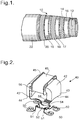
- a flexible riser 10 which acts as a hose to carry a pressurised fluid, has several concentric layers.
- An innermost layer 12 of helically wound bent steel strip provides resistance against external pressures, and a similar helically wound steel strip layer 14 provides hoop strength, and between these layers is a fluid barrier layer 16 of polymeric material.
- These are surrounded by two layers 18 and 20 of helically-wound steel ligaments or wires to provide tensile strength, the steel ligaments or wires within each layer 18 and 20 being wound side-by-side.
- adjacent ligaments or wires within a layer 18 or 20 are shown as being in contact, in practice there are narrow gaps between adjacent wires within the layer 18 or 20; such gaps ensure the flexibility of the riser 10. For example there may be 5 mm wide gaps between adjacent ligaments or wires in each layer 18 and 20, although in practice the gaps will not be of constant or consistent width as the riser 10 flexes.
- a polymeric layer 22 provides an external sleeve and fluid barrier; this layer 22 may be of thickness up to 30 mm, for example 20 mm or 12 mm.
- the failure mode with such a riser 10 is typically the failure of one or more ligaments in the outermost layer 20. But it will be appreciated that these ligaments cannot be observed directly, because they are enclosed within the polymeric layer 22.
- the stresses in the outer layers 18 and 20 of steel ligaments of a riser 10 as shown in figure 1 may be monitored using an electromagnetic stress-measuring probe 40.
- each wire is of width 12 mm and thickness 5 mm, and the wires are covered by a layer 22 of polymer that may be 12 mm or 20 mm thick.
- each layer 18 and 20 consists of a single layer of side-by-side wires.
- the probe 40 comprises a U-core 42 of laminated high-permeability silicon/iron alloy defining two poles 43 whose pole faces 44 are separated by a gap about 60 mm wide, and are each of width 60 mm, and of thickness 18 mm.
- the pole faces 44 are slightly curved to conform to the outer surface of the riser 10.
- a former 45 Around the upper end of the U-core 42 is a former 45 on which is wound a drive coil 46.
- This coil 46 in operation of the probe 10, is supplied with an alternating sinusoidal drive current such that the alternating magnetic field induced in the steel wires below the surface of the riser 10 is considerably less than saturation.
- the drive current is supplied by a control unit 60 (shown in figure 4 ).
- the probe 40 also comprises four flat sensor coils 50 each wound around a square former of side 17 mm, each coil being connected by a pair of wires 51 to a printed circuit board 52 that includes a head amplifier 54.
- the probe 40 also includes a temperature sensor 56 that is also connected to the printed circuit board 52.
- a flexible multi-wire strip 58 carries output signals from the head amplifier 54 to a signal analysis unit in the control unit 60.
- the sensor coils 50 are shown separated from the U-core 42, but in reality in the assembled probe 40 the sensor coils 50 are secured to the pole faces 44 near the corners of the probe 40, two sensor coils 50 being attached on each pole face 44. They may be fixed by adhesive, or they may be secured within a frame that is fixed to the U-core 42.
- the sensor coils 50 are sufficiently small that if the probe 40 is suitably oriented each one is sensitive to a different steel wire within the riser, so that the properties of the separate wires can be distinguished, and can be measured simultaneously.
- this arrangement provides greater resolution than would be possible using a sensor coil wound onto the core 42 or overwound onto the drive coil 46.
- greater resolution could be obtained using even smaller sensors, for example of width less than the width of a steel wire, there would be significantly greater fluctuation from position to position, because of gaps between adjacent wires. It will be appreciated that the wires cannot be seen, because of the polymeric layer 22, so the sensors cannot be visually aligned with the wires.
- the probe 40 may be used to measure stress in a ferromagnetic object (such as the wires in the layers 18 or 20) by a method such as that described in EP 1 436 604 .
- a ferromagnetic object such as the wires in the layers 18 or 20
- an alternating current of a desired frequency and amplitude is supplied to the drive coil 46, so the magnetic field in the object oscillates with an amplitude much less than saturation.
- the magnetic field may oscillate about zero, or alternatively there may be a steady magnetic field in addition to the alternating magnetic field.
- the sensor coils 50 provide signals, and the signals are analysed into components in phase and in quadrature with the alternating current supplied to the drive coil 46. Before the signals are processed they may be amplified and digitised.
- FIG 3 shows a diagrammatic plan view of the probe 40 in use adjacent to the outer surface of the riser 10.
- the figure is diagrammatic, and is intended to indicate the relative orientations, and therefore shows simultaneously features which are in different planes and are in reality not visible.
- the line A represents a line along the surface of the riser 10 parallel to its longitudinal axis; some of the wires of the outer layer 20 are shown in solid lines (only five are shown), and some of the wires of the intermediate layer 18 are shown in broken lines (only three are shown).
- the wires in the outer layer 20 are in directions at an angle between 25° and 42° to the direction of the line A, while the wires in the intermediate layer 18 are at an angle that may be the same, or may be up to 4° different, but inclined in the opposite direction.
- the wires in the outer layer 20 may be at an orientation of +33°, and the wires in the intermediate layer 18 at an orientation of -34°, relative to the line A.
- the probe 40 is shown as being arranged such that a straight line between the centres of the pole faces 44 (corresponding to the free space direction of the magnetic field) is at an angle ⁇ to the orientation of the wires in the outer layer 20.
- This angle ⁇ is shown as about 47° by way of example, but it will be appreciated that somewhat different results will be obtained if the probe 40 is at different angles ⁇ .
- each sensor coil 50 locates above a different wire in the outer layer 20; each sensor coil 50 locates above a different wire in the intermediate layer 18; none of the wires in the outer layer 20 links the opposed pole faces 44; and none of the wires in the intermediate layer 18 links the opposed pole faces 44.
- the probe 40 is arranged so that the angle ⁇ is 90°, then it would no longer be the case that each sensor coil 50 would locate above a different wire in the outer layer 20; and at least some of the wires in the intermediate layer 18 would link the opposed pole faces 44, and so link the poles 43.
- the probe 40 is arranged so that the angle ⁇ is 30°, then at least some of the wires in the outer layer 20 would link the opposed pole faces 44, and so the poles 43.
- measurements are made with probes 40 that are set at angles ⁇ equal to -30°, +30°, +60°, and +90°.
- the orientation of the probe 40 is desirably selected to take into account the orientations of the wires in the layers 18 and 20.
- the orientations of the probe 40 may be selected to achieve the following four situations: the poles 43 are linked by wires in the outer layer 20 but not linked by those in the adjacent layer 18; the poles 43 are not linked by wires in either the outer layer 20 or the adjacent layer 18; the poles 43 are not linked by wires in the outer layer 20 but are linked by those in the adjacent layer 18; and the poles 43 are linked by ligaments in both the layers 18 and 20.
- the poles 43 are linked by wires in the outer layer 20 but not linked by those in the adjacent layer 18; the poles 43 are linked by ligaments in both the layers 18 and 20.
- the phrase "the poles 43 are linked" by specific wires means that those specific wires pass directly under both the poles 43 of the probe 40; consequently magnetic field lines between the poles 43 will tend to follow paths that extend longitudinally along such specific wires. Those specific wires hence form part of a magnetic circuit that links the poles 43. In a plan view corresponding to figure 3 , i.e. looking in a radial direction towards the longitudinal axis of the riser 10, the lines that represent the specific wires will therefore intersect both the rectangles that represent the pole faces 44.
- the orientations of the wires in the layers 18 and 20 are usually known, and the scanning direction is known.
- the sensor coils 50 are sufficiently small that each sensor coil 50 lies above a different wire in both the layers 18 and 20, then if the probe 40 is scanned in a given direction (for example the upwards direction parallel to the line A), and there is one broken wire, then the sequence in which the separate sensor coils 50 pass over the broken wire will depend upon whether the broken wire is in the outer layer 20 or the inner layer 18. This helps distinguish between broken wires in different layers 18 and 20.
- measurements may also be taken with different stresses in the riser 10, for example by changing the pressure of the fluids within the riser 10.
- This should change the stresses in all the wires or ligaments in both layers 18 and 20, and can assist in distinguishing between residual stresses and applied stresses. In some cases the residual stresses vary significantly between the different wires or ligaments in each layer 18 and 20.
- the externally-applied stress in the riser 10 should change the stresses in all the wires or ligaments, but if a wire or ligament is broken then its stress will not be significantly altered by changes in the externally-applied stress. Hence the presence of a broken wire or ligament may be detected from the observation that the measured stress in that broken wire or ligament is not altered by a change in the externally-applied stress.
- the measurements at different frequencies and at different orientations will be sensitive to different extents on the stresses in the wires or ligaments in the different layers 18 and 20, and may also be sensitive to stresses in the steel strip layer 14.
- the measurements can therefore be combined algebraically to provide stress-sensitive parameters that are predominantly sensitive to stresses in a single one of the layers 14, 18 or 20.
- the presence of a broken wire or ligament in the layer 18 can for example be distinguished from the presence of a broken wire or ligament in the layer 20.
- FIG 4 shows a side view of the probe 40 during inspection of the riser 10.
- a scanning mechanism 62 includes two collars 63 and 64 which are clamped onto the riser 10.
- a threaded drive shaft 65 extends between a bearing 66 held by the collar 63, and an electric motor 67 held by the collar 64.
- the probe 40 is attached to a support bar 68 which engages with the threaded drive shaft 65.
- the probe 40 is set up at an appropriate angle ⁇ , such as 60°; and the electric motor 67 is repeatedly and briefly activated to rotate the drive shaft 65 and consequently move the probe 40 along the riser 10.
- the probe 40 is scanned along a line parallel to the line A shown in figure 3 , being moved in steps, and at each successive position measurements are made.
- the probe 40 is moved along a distance no more than 15 mm, for example no more than 10 mm.
- the probe 40 is moved along by 4 mm at each step, this distance being less than the separation between adjacent wires in the layer 18 and in the layer 20.
- measurements are made at a range of different frequencies.
- measurements may be made at at least six different frequencies between 20 Hz and 3000 Hz, e.g. at 35 Hz, 70 Hz, 140 Hz, 280 Hz, 560 Hz, 1200 Hz, 1600 Hz, 2400 Hz and 2900 Hz.
- the frequencies may be selected between 20 Hz and 1000 Hz.
- the probe 40 will eventually pass over every wire in each layer 18 and 20; the length of the drive shaft 65 is at least as long as the helical pitch of the wires in the layers 18 and 20, to ensure that every wire in each layer 18 and 20 is scanned.
- Additional measurements may be obtained by setting up a probe 40 at a different angle ⁇ , and repeating the procedure described above. If the probe 40 has a face that is shaped to fit the outer surface of the riser 10, this would normally require a different probe 40.
- the first stage of the signal analysis involves digitisation, and resolving the signals into in-phase and quadrature components. Backing off (removal of a constant value) may optionally also be applied to the signals. The resulting signals may be used to obtain a stress-dependent measurement that is unaffected by lift-off, and so to deduce values of stress in the wires.
- the radial distance between the wire and the probe by variation in the spacing of the wires, and by the presence of any current loops.
- the measurements at multiple different frequencies enable them to be distinguished from each other.
- measurements may be made at different stresses, for example by altering the fluid pressure within the riser 10.
- the signals can be analysed to provide information on stress in the wires of the intermediate layer 18, or stress in the wires of the outer layer 20, or the separation of the wires in the intermediate layer 18, or the separation of the wires in the outer layer 20.
- the scanning mechanism 62 is shown by way of example.
- the scanning mechanism 62 may be modified in various ways, for example by providing a motor attached to the probe 40, and having a stationary threaded shaft 65.
- the probe 40 might be guided and supported by a guide rod (equivalent to the drive shaft 65), the probe 40 also carrying a motor driving a wheel that engages the outer surface of the riser 10, so the probe 40 moves itself along the riser 10.
- the mechanism may be arranged to scan a probe 40 along a different path.
- an alternative scanning mechanism is arranged to scan the probe 40 along a circular path around the circumference of the riser 10.
- this shows a scanner 70 arranged to scan three probes 40 circumferentially around a riser 10 (the internal structure of the riser 10 not being shown).
- a ring 72 is clamped around the riser 10, and the scanner 70 has a frame 71 linked to this ring 72 so it can move circumferentially but not axially.
- the scanner 70 includes three probes 40, each probe 40 being enclosed within a plastic casing 73, and being connected to a respective control unit 60; power and data cables 74 are connected to each control unit 60.
- the frame 71 is in three parts, one part arranged to carry each plastic casing 73, and the parts are linked together: two of the links are provided by pivoted linking bars 75, while the third link comprises adjustable tie rods 76.
- Each plastic casing 73 is held into the frame 71 by spring-loaded bolts 77, which urge the poles 43 of the probes 40 towards the riser 10, and the frame 71 includes wheels 79 on either side of each probe 40, the wheels 79 resting on the surface of the riser 10.
- the provision of the tie rods 76 and the spring loaded bolts 77 ensures that risers 10 of different diameters can be accommodated.
- Almost all the components of the scanner 70 are of hard engineering plastic, to minimise their magnetic effect; and the springs are of stainless steel.
- a motor and drive wheel module 80 At the end of the frame 71 furthest from the ring 72 is a motor and drive wheel module 80, to which drive cables 82 are connected.
- the motor and drive wheel module 80 includes an electric motor which drives a drive wheel pressed against the outer surface of the riser, the rotation axis of the drive wheel being parallel to the longitudinal axis of the riser 10. Actuation of the module 80 therefore moves the frame 71 and the three probes 40 circumferentially around the riser 10, guided by the ring 72.
- the scanner 70 is repeatedly moved a short distance, preferably no more than 15 mm, for example 4 or 5 mm, and at each new position of each probe 40 measurements are taken at a range of different frequencies with each probe 40.
- the signal analysis is substantially equivalent to that described above.
Landscapes
- Physics & Mathematics (AREA)
- General Physics & Mathematics (AREA)
- Chemical & Material Sciences (AREA)
- Chemical Kinetics & Catalysis (AREA)
- Electrochemistry (AREA)
- Health & Medical Sciences (AREA)
- Life Sciences & Earth Sciences (AREA)
- Analytical Chemistry (AREA)
- Biochemistry (AREA)
- General Health & Medical Sciences (AREA)
- Immunology (AREA)
- Pathology (AREA)
- Investigating Or Analyzing Materials By The Use Of Magnetic Means (AREA)
Applications Claiming Priority (2)
| Application Number | Priority Date | Filing Date | Title |
|---|---|---|---|
| GBGB1222927.4A GB201222927D0 (en) | 2012-12-19 | 2012-12-19 | Detecting failures in flexible multistrand steel structures |
| PCT/GB2013/053338 WO2014096817A1 (en) | 2012-12-19 | 2013-12-18 | Detecting failures in flexible multistrand steel structures |
Publications (2)
| Publication Number | Publication Date |
|---|---|
| EP2936136A1 EP2936136A1 (en) | 2015-10-28 |
| EP2936136B1 true EP2936136B1 (en) | 2018-03-21 |
Family
ID=47631017
Family Applications (1)
| Application Number | Title | Priority Date | Filing Date |
|---|---|---|---|
| EP13821504.1A Active EP2936136B1 (en) | 2012-12-19 | 2013-12-18 | Detecting failures in flexible multistrand steel structures |
Country Status (7)
| Country | Link |
|---|---|
| EP (1) | EP2936136B1 (da) |
| AU (1) | AU2013366108B2 (da) |
| BR (1) | BR112015014552B1 (da) |
| CA (1) | CA2895447C (da) |
| DK (1) | DK2936136T3 (da) |
| GB (1) | GB201222927D0 (da) |
| WO (1) | WO2014096817A1 (da) |
Cited By (1)
| Publication number | Priority date | Publication date | Assignee | Title |
|---|---|---|---|---|
| WO2025011776A1 (en) * | 2023-07-07 | 2025-01-16 | Baker Hughes Energy Technology UK Limited | A method and apparatus for monitoring stress in steel ligaments within a flexible pipe |
Families Citing this family (3)
| Publication number | Priority date | Publication date | Assignee | Title |
|---|---|---|---|---|
| GB2549611B (en) * | 2016-04-22 | 2020-12-23 | Ge Oil & Gas Uk Ltd | Hoses, and detecting failures in reinforced hoses |
| FR3062481A1 (fr) * | 2017-02-02 | 2018-08-03 | Commissariat A L'energie Atomique Et Aux Energies Alternatives | Dispositif et procede electromagnetique de detection de defauts |
| CN119733584B (zh) * | 2024-12-26 | 2025-06-27 | 文天精策仪器科技(苏州)有限公司 | 一种探针冷热台及其探针调节方法 |
Citations (1)
| Publication number | Priority date | Publication date | Assignee | Title |
|---|---|---|---|---|
| US20020186023A1 (en) * | 2001-06-07 | 2002-12-12 | Kliman Gerald Burt | Method and system for detecting core faults |
Family Cites Families (3)
| Publication number | Priority date | Publication date | Assignee | Title |
|---|---|---|---|---|
| GB0314747D0 (en) * | 2003-06-25 | 2003-07-30 | Aea Technology Plc | Detecting failures in flexible multristrand steel structures |
| GB0428138D0 (en) * | 2004-12-23 | 2005-01-26 | Aea Technology Plc | Detecting failures in flexible multistrand steel structures |
| GB2475314B8 (en) * | 2009-11-16 | 2013-09-25 | Innospection Group Ltd | Remote environment inspection apparatus and method |
-
2012
- 2012-12-19 GB GBGB1222927.4A patent/GB201222927D0/en not_active Ceased
-
2013
- 2013-12-18 EP EP13821504.1A patent/EP2936136B1/en active Active
- 2013-12-18 AU AU2013366108A patent/AU2013366108B2/en active Active
- 2013-12-18 DK DK13821504.1T patent/DK2936136T3/da active
- 2013-12-18 BR BR112015014552-3A patent/BR112015014552B1/pt active IP Right Grant
- 2013-12-18 CA CA2895447A patent/CA2895447C/en active Active
- 2013-12-18 WO PCT/GB2013/053338 patent/WO2014096817A1/en not_active Ceased
Patent Citations (1)
| Publication number | Priority date | Publication date | Assignee | Title |
|---|---|---|---|---|
| US20020186023A1 (en) * | 2001-06-07 | 2002-12-12 | Kliman Gerald Burt | Method and system for detecting core faults |
Cited By (1)
| Publication number | Priority date | Publication date | Assignee | Title |
|---|---|---|---|---|
| WO2025011776A1 (en) * | 2023-07-07 | 2025-01-16 | Baker Hughes Energy Technology UK Limited | A method and apparatus for monitoring stress in steel ligaments within a flexible pipe |
Also Published As
| Publication number | Publication date |
|---|---|
| AU2013366108B2 (en) | 2017-05-18 |
| CA2895447C (en) | 2021-05-25 |
| BR112015014552A2 (pt) | 2017-09-26 |
| GB201222927D0 (en) | 2013-01-30 |
| WO2014096817A1 (en) | 2014-06-26 |
| DK2936136T3 (da) | 2018-05-07 |
| BR112015014552B1 (pt) | 2020-09-29 |
| CA2895447A1 (en) | 2014-06-26 |
| EP2936136A1 (en) | 2015-10-28 |
| AU2013366108A1 (en) | 2015-07-09 |
Similar Documents
| Publication | Publication Date | Title |
|---|---|---|
| US4492115A (en) | Method and apparatus for measuring defects in ferromagnetic tubing | |
| CA2815623C (en) | Remote environment inspection apparatus and method | |
| CN109073599B (zh) | 软管以及加强软管中的失效检测 | |
| US8468898B2 (en) | Method and apparatus for continuous sectional magnetic encoding to measure torque on large shafts | |
| CA2895447C (en) | Detecting failures in flexible multistrand steel structures | |
| US10634645B2 (en) | Eddy current probe with 3-D excitation coils | |
| NO339066B1 (no) | Påvisning av defekter i fleksible flertråds stålstrukturer | |
| WO1994028407A1 (en) | Stress measurement | |
| EP1636578B1 (en) | Detecting failures of flexible multistrand steel structures | |
| EP4739986A1 (en) | A method and apparatus for monitoring stress in steel ligaments within a flexible pipe |
Legal Events
| Date | Code | Title | Description |
|---|---|---|---|
| PUAI | Public reference made under article 153(3) epc to a published international application that has entered the european phase |
Free format text: ORIGINAL CODE: 0009012 |
|
| 17P | Request for examination filed |
Effective date: 20150701 |
|
| AK | Designated contracting states |
Kind code of ref document: A1 Designated state(s): AL AT BE BG CH CY CZ DE DK EE ES FI FR GB GR HR HU IE IS IT LI LT LU LV MC MK MT NL NO PL PT RO RS SE SI SK SM TR |
|
| AX | Request for extension of the european patent |
Extension state: BA ME |
|
| DAX | Request for extension of the european patent (deleted) | ||
| REG | Reference to a national code |
Ref country code: DE Ref legal event code: R079 Ref document number: 602013034818 Country of ref document: DE Free format text: PREVIOUS MAIN CLASS: G01N0027900000 Ipc: G01N0027720000 |
|
| GRAP | Despatch of communication of intention to grant a patent |
Free format text: ORIGINAL CODE: EPIDOSNIGR1 |
|
| RIC1 | Information provided on ipc code assigned before grant |
Ipc: G01L 1/12 20060101ALN20171017BHEP Ipc: G01N 27/90 20060101ALN20171017BHEP Ipc: G01N 27/72 20060101AFI20171017BHEP |
|
| RIC1 | Information provided on ipc code assigned before grant |
Ipc: G01N 27/90 20060101ALN20171023BHEP Ipc: G01N 27/72 20060101AFI20171023BHEP Ipc: G01L 1/12 20060101ALN20171023BHEP |
|
| INTG | Intention to grant announced |
Effective date: 20171114 |
|
| GRAS | Grant fee paid |
Free format text: ORIGINAL CODE: EPIDOSNIGR3 |
|
| GRAA | (expected) grant |
Free format text: ORIGINAL CODE: 0009210 |
|
| AK | Designated contracting states |
Kind code of ref document: B1 Designated state(s): AL AT BE BG CH CY CZ DE DK EE ES FI FR GB GR HR HU IE IS IT LI LT LU LV MC MK MT NL NO PL PT RO RS SE SI SK SM TR |
|
| REG | Reference to a national code |
Ref country code: GB Ref legal event code: FG4D |
|
| REG | Reference to a national code |
Ref country code: CH Ref legal event code: EP |
|
| REG | Reference to a national code |
Ref country code: AT Ref legal event code: REF Ref document number: 981660 Country of ref document: AT Kind code of ref document: T Effective date: 20180415 |
|
| REG | Reference to a national code |
Ref country code: IE Ref legal event code: FG4D |
|
| REG | Reference to a national code |
Ref country code: DE Ref legal event code: R096 Ref document number: 602013034818 Country of ref document: DE |
|
| REG | Reference to a national code |
Ref country code: NL Ref legal event code: FP |
|
| REG | Reference to a national code |
Ref country code: DK Ref legal event code: T3 Effective date: 20180502 |
|
| REG | Reference to a national code |
Ref country code: NO Ref legal event code: T2 Effective date: 20180321 |
|
| PG25 | Lapsed in a contracting state [announced via postgrant information from national office to epo] |
Ref country code: CY Free format text: LAPSE BECAUSE OF FAILURE TO SUBMIT A TRANSLATION OF THE DESCRIPTION OR TO PAY THE FEE WITHIN THE PRESCRIBED TIME-LIMIT Effective date: 20180321 Ref country code: LT Free format text: LAPSE BECAUSE OF FAILURE TO SUBMIT A TRANSLATION OF THE DESCRIPTION OR TO PAY THE FEE WITHIN THE PRESCRIBED TIME-LIMIT Effective date: 20180321 Ref country code: HR Free format text: LAPSE BECAUSE OF FAILURE TO SUBMIT A TRANSLATION OF THE DESCRIPTION OR TO PAY THE FEE WITHIN THE PRESCRIBED TIME-LIMIT Effective date: 20180321 Ref country code: FI Free format text: LAPSE BECAUSE OF FAILURE TO SUBMIT A TRANSLATION OF THE DESCRIPTION OR TO PAY THE FEE WITHIN THE PRESCRIBED TIME-LIMIT Effective date: 20180321 |
|
| REG | Reference to a national code |
Ref country code: LT Ref legal event code: MG4D |
|
| REG | Reference to a national code |
Ref country code: AT Ref legal event code: MK05 Ref document number: 981660 Country of ref document: AT Kind code of ref document: T Effective date: 20180321 |
|
| PG25 | Lapsed in a contracting state [announced via postgrant information from national office to epo] |
Ref country code: BG Free format text: LAPSE BECAUSE OF FAILURE TO SUBMIT A TRANSLATION OF THE DESCRIPTION OR TO PAY THE FEE WITHIN THE PRESCRIBED TIME-LIMIT Effective date: 20180621 Ref country code: GR Free format text: LAPSE BECAUSE OF FAILURE TO SUBMIT A TRANSLATION OF THE DESCRIPTION OR TO PAY THE FEE WITHIN THE PRESCRIBED TIME-LIMIT Effective date: 20180622 Ref country code: LV Free format text: LAPSE BECAUSE OF FAILURE TO SUBMIT A TRANSLATION OF THE DESCRIPTION OR TO PAY THE FEE WITHIN THE PRESCRIBED TIME-LIMIT Effective date: 20180321 Ref country code: RS Free format text: LAPSE BECAUSE OF FAILURE TO SUBMIT A TRANSLATION OF THE DESCRIPTION OR TO PAY THE FEE WITHIN THE PRESCRIBED TIME-LIMIT Effective date: 20180321 Ref country code: SE Free format text: LAPSE BECAUSE OF FAILURE TO SUBMIT A TRANSLATION OF THE DESCRIPTION OR TO PAY THE FEE WITHIN THE PRESCRIBED TIME-LIMIT Effective date: 20180321 |
|
| PG25 | Lapsed in a contracting state [announced via postgrant information from national office to epo] |
Ref country code: PL Free format text: LAPSE BECAUSE OF FAILURE TO SUBMIT A TRANSLATION OF THE DESCRIPTION OR TO PAY THE FEE WITHIN THE PRESCRIBED TIME-LIMIT Effective date: 20180321 Ref country code: ES Free format text: LAPSE BECAUSE OF FAILURE TO SUBMIT A TRANSLATION OF THE DESCRIPTION OR TO PAY THE FEE WITHIN THE PRESCRIBED TIME-LIMIT Effective date: 20180321 Ref country code: AL Free format text: LAPSE BECAUSE OF FAILURE TO SUBMIT A TRANSLATION OF THE DESCRIPTION OR TO PAY THE FEE WITHIN THE PRESCRIBED TIME-LIMIT Effective date: 20180321 Ref country code: RO Free format text: LAPSE BECAUSE OF FAILURE TO SUBMIT A TRANSLATION OF THE DESCRIPTION OR TO PAY THE FEE WITHIN THE PRESCRIBED TIME-LIMIT Effective date: 20180321 Ref country code: IT Free format text: LAPSE BECAUSE OF FAILURE TO SUBMIT A TRANSLATION OF THE DESCRIPTION OR TO PAY THE FEE WITHIN THE PRESCRIBED TIME-LIMIT Effective date: 20180321 Ref country code: EE Free format text: LAPSE BECAUSE OF FAILURE TO SUBMIT A TRANSLATION OF THE DESCRIPTION OR TO PAY THE FEE WITHIN THE PRESCRIBED TIME-LIMIT Effective date: 20180321 |
|
| PG25 | Lapsed in a contracting state [announced via postgrant information from national office to epo] |
Ref country code: CZ Free format text: LAPSE BECAUSE OF FAILURE TO SUBMIT A TRANSLATION OF THE DESCRIPTION OR TO PAY THE FEE WITHIN THE PRESCRIBED TIME-LIMIT Effective date: 20180321 Ref country code: AT Free format text: LAPSE BECAUSE OF FAILURE TO SUBMIT A TRANSLATION OF THE DESCRIPTION OR TO PAY THE FEE WITHIN THE PRESCRIBED TIME-LIMIT Effective date: 20180321 Ref country code: SM Free format text: LAPSE BECAUSE OF FAILURE TO SUBMIT A TRANSLATION OF THE DESCRIPTION OR TO PAY THE FEE WITHIN THE PRESCRIBED TIME-LIMIT Effective date: 20180321 Ref country code: SK Free format text: LAPSE BECAUSE OF FAILURE TO SUBMIT A TRANSLATION OF THE DESCRIPTION OR TO PAY THE FEE WITHIN THE PRESCRIBED TIME-LIMIT Effective date: 20180321 |
|
| PG25 | Lapsed in a contracting state [announced via postgrant information from national office to epo] |
Ref country code: PT Free format text: LAPSE BECAUSE OF FAILURE TO SUBMIT A TRANSLATION OF THE DESCRIPTION OR TO PAY THE FEE WITHIN THE PRESCRIBED TIME-LIMIT Effective date: 20180723 |
|
| REG | Reference to a national code |
Ref country code: DE Ref legal event code: R097 Ref document number: 602013034818 Country of ref document: DE |
|
| PLBE | No opposition filed within time limit |
Free format text: ORIGINAL CODE: 0009261 |
|
| STAA | Information on the status of an ep patent application or granted ep patent |
Free format text: STATUS: NO OPPOSITION FILED WITHIN TIME LIMIT |
|
| 26N | No opposition filed |
Effective date: 20190102 |
|
| PG25 | Lapsed in a contracting state [announced via postgrant information from national office to epo] |
Ref country code: SI Free format text: LAPSE BECAUSE OF FAILURE TO SUBMIT A TRANSLATION OF THE DESCRIPTION OR TO PAY THE FEE WITHIN THE PRESCRIBED TIME-LIMIT Effective date: 20180321 |
|
| REG | Reference to a national code |
Ref country code: DE Ref legal event code: R119 Ref document number: 602013034818 Country of ref document: DE |
|
| REG | Reference to a national code |
Ref country code: CH Ref legal event code: PL |
|
| PG25 | Lapsed in a contracting state [announced via postgrant information from national office to epo] |
Ref country code: MC Free format text: LAPSE BECAUSE OF FAILURE TO SUBMIT A TRANSLATION OF THE DESCRIPTION OR TO PAY THE FEE WITHIN THE PRESCRIBED TIME-LIMIT Effective date: 20180321 Ref country code: LU Free format text: LAPSE BECAUSE OF NON-PAYMENT OF DUE FEES Effective date: 20181218 |
|
| REG | Reference to a national code |
Ref country code: IE Ref legal event code: MM4A |
|
| REG | Reference to a national code |
Ref country code: BE Ref legal event code: MM Effective date: 20181231 |
|
| PG25 | Lapsed in a contracting state [announced via postgrant information from national office to epo] |
Ref country code: DE Free format text: LAPSE BECAUSE OF NON-PAYMENT OF DUE FEES Effective date: 20190702 Ref country code: IE Free format text: LAPSE BECAUSE OF NON-PAYMENT OF DUE FEES Effective date: 20181218 |
|
| PG25 | Lapsed in a contracting state [announced via postgrant information from national office to epo] |
Ref country code: BE Free format text: LAPSE BECAUSE OF NON-PAYMENT OF DUE FEES Effective date: 20181231 |
|
| PG25 | Lapsed in a contracting state [announced via postgrant information from national office to epo] |
Ref country code: CH Free format text: LAPSE BECAUSE OF NON-PAYMENT OF DUE FEES Effective date: 20181231 Ref country code: LI Free format text: LAPSE BECAUSE OF NON-PAYMENT OF DUE FEES Effective date: 20181231 |
|
| PG25 | Lapsed in a contracting state [announced via postgrant information from national office to epo] |
Ref country code: MT Free format text: LAPSE BECAUSE OF NON-PAYMENT OF DUE FEES Effective date: 20181218 |
|
| PG25 | Lapsed in a contracting state [announced via postgrant information from national office to epo] |
Ref country code: TR Free format text: LAPSE BECAUSE OF FAILURE TO SUBMIT A TRANSLATION OF THE DESCRIPTION OR TO PAY THE FEE WITHIN THE PRESCRIBED TIME-LIMIT Effective date: 20180321 |
|
| PG25 | Lapsed in a contracting state [announced via postgrant information from national office to epo] |
Ref country code: HU Free format text: LAPSE BECAUSE OF FAILURE TO SUBMIT A TRANSLATION OF THE DESCRIPTION OR TO PAY THE FEE WITHIN THE PRESCRIBED TIME-LIMIT; INVALID AB INITIO Effective date: 20131218 Ref country code: MK Free format text: LAPSE BECAUSE OF NON-PAYMENT OF DUE FEES Effective date: 20180321 |
|
| PG25 | Lapsed in a contracting state [announced via postgrant information from national office to epo] |
Ref country code: IS Free format text: LAPSE BECAUSE OF FAILURE TO SUBMIT A TRANSLATION OF THE DESCRIPTION OR TO PAY THE FEE WITHIN THE PRESCRIBED TIME-LIMIT Effective date: 20180721 |
|
| PGFP | Annual fee paid to national office [announced via postgrant information from national office to epo] |
Ref country code: NL Payment date: 20251119 Year of fee payment: 13 |
|
| PGFP | Annual fee paid to national office [announced via postgrant information from national office to epo] |
Ref country code: GB Payment date: 20251119 Year of fee payment: 13 |
|
| PGFP | Annual fee paid to national office [announced via postgrant information from national office to epo] |
Ref country code: NO Payment date: 20251121 Year of fee payment: 13 |
|
| PGFP | Annual fee paid to national office [announced via postgrant information from national office to epo] |
Ref country code: DK Payment date: 20251119 Year of fee payment: 13 |
|
| PGFP | Annual fee paid to national office [announced via postgrant information from national office to epo] |
Ref country code: FR Payment date: 20251120 Year of fee payment: 13 |