EP2935955B1 - Valve wedge for a slide valve - Google Patents
Valve wedge for a slide valve Download PDFInfo
- Publication number
- EP2935955B1 EP2935955B1 EP13811237.0A EP13811237A EP2935955B1 EP 2935955 B1 EP2935955 B1 EP 2935955B1 EP 13811237 A EP13811237 A EP 13811237A EP 2935955 B1 EP2935955 B1 EP 2935955B1
- Authority
- EP
- European Patent Office
- Prior art keywords
- ribs
- core
- valve
- shoes
- slide
- Prior art date
- Legal status (The legal status is an assumption and is not a legal conclusion. Google has not performed a legal analysis and makes no representation as to the accuracy of the status listed.)
- Active
Links
Images


Classifications
-
- F—MECHANICAL ENGINEERING; LIGHTING; HEATING; WEAPONS; BLASTING
- F16—ENGINEERING ELEMENTS AND UNITS; GENERAL MEASURES FOR PRODUCING AND MAINTAINING EFFECTIVE FUNCTIONING OF MACHINES OR INSTALLATIONS; THERMAL INSULATION IN GENERAL
- F16K—VALVES; TAPS; COCKS; ACTUATING-FLOATS; DEVICES FOR VENTING OR AERATING
- F16K3/00—Gate valves or sliding valves, i.e. cut-off apparatus with closing members having a sliding movement along the seat for opening and closing
- F16K3/02—Gate valves or sliding valves, i.e. cut-off apparatus with closing members having a sliding movement along the seat for opening and closing with flat sealing faces; Packings therefor
- F16K3/12—Gate valves or sliding valves, i.e. cut-off apparatus with closing members having a sliding movement along the seat for opening and closing with flat sealing faces; Packings therefor with wedge-shaped arrangements of sealing faces
-
- B—PERFORMING OPERATIONS; TRANSPORTING
- B29—WORKING OF PLASTICS; WORKING OF SUBSTANCES IN A PLASTIC STATE IN GENERAL
- B29C—SHAPING OR JOINING OF PLASTICS; SHAPING OF MATERIAL IN A PLASTIC STATE, NOT OTHERWISE PROVIDED FOR; AFTER-TREATMENT OF THE SHAPED PRODUCTS, e.g. REPAIRING
- B29C45/00—Injection moulding, i.e. forcing the required volume of moulding material through a nozzle into a closed mould; Apparatus therefor
- B29C45/14—Injection moulding, i.e. forcing the required volume of moulding material through a nozzle into a closed mould; Apparatus therefor incorporating preformed parts or layers, e.g. injection moulding around inserts or for coating articles
- B29C45/14819—Injection moulding, i.e. forcing the required volume of moulding material through a nozzle into a closed mould; Apparatus therefor incorporating preformed parts or layers, e.g. injection moulding around inserts or for coating articles the inserts being completely encapsulated
-
- B—PERFORMING OPERATIONS; TRANSPORTING
- B29—WORKING OF PLASTICS; WORKING OF SUBSTANCES IN A PLASTIC STATE IN GENERAL
- B29C—SHAPING OR JOINING OF PLASTICS; SHAPING OF MATERIAL IN A PLASTIC STATE, NOT OTHERWISE PROVIDED FOR; AFTER-TREATMENT OF THE SHAPED PRODUCTS, e.g. REPAIRING
- B29C45/00—Injection moulding, i.e. forcing the required volume of moulding material through a nozzle into a closed mould; Apparatus therefor
- B29C45/14—Injection moulding, i.e. forcing the required volume of moulding material through a nozzle into a closed mould; Apparatus therefor incorporating preformed parts or layers, e.g. injection moulding around inserts or for coating articles
- B29C2045/1486—Details, accessories and auxiliary operations
- B29C2045/14868—Pretreatment of the insert, e.g. etching, cleaning
-
- B—PERFORMING OPERATIONS; TRANSPORTING
- B29—WORKING OF PLASTICS; WORKING OF SUBSTANCES IN A PLASTIC STATE IN GENERAL
- B29K—INDEXING SCHEME ASSOCIATED WITH SUBCLASSES B29B, B29C OR B29D, RELATING TO MOULDING MATERIALS OR TO MATERIALS FOR MOULDS, REINFORCEMENTS, FILLERS OR PREFORMED PARTS, e.g. INSERTS
- B29K2021/00—Use of unspecified rubbers as moulding material
-
- B—PERFORMING OPERATIONS; TRANSPORTING
- B29—WORKING OF PLASTICS; WORKING OF SUBSTANCES IN A PLASTIC STATE IN GENERAL
- B29K—INDEXING SCHEME ASSOCIATED WITH SUBCLASSES B29B, B29C OR B29D, RELATING TO MOULDING MATERIALS OR TO MATERIALS FOR MOULDS, REINFORCEMENTS, FILLERS OR PREFORMED PARTS, e.g. INSERTS
- B29K2705/00—Use of metals, their alloys or their compounds, for preformed parts, e.g. for inserts
-
- B—PERFORMING OPERATIONS; TRANSPORTING
- B29—WORKING OF PLASTICS; WORKING OF SUBSTANCES IN A PLASTIC STATE IN GENERAL
- B29L—INDEXING SCHEME ASSOCIATED WITH SUBCLASS B29C, RELATING TO PARTICULAR ARTICLES
- B29L2031/00—Other particular articles
- B29L2031/748—Machines or parts thereof not otherwise provided for
- B29L2031/7506—Valves
Definitions
- the present invention relates to the technical field of slide valves and in particular to a valve wedge for a slide valve comprising a rough cast metal wedge for a slide valve comprising a rough cast metal wedge core encapsulated in, i.e. coated with, a soft seal encapsulation, i.e.
- each of said guide members comprising a sideways projecting rib of said rough cast wedge core and a prefabricated wear and corrosion-resistant slide shoe arranged thereon, each rib comprising laterally opposite lateral surfaces and an end-face and each shoe comprising two opposite lateral walls with inner surfaces and outer surfaces adapted for interacting with corresponding slide surfaces of the guide grooves and each shoe being fixedly connected with or vulcanized to the respective one of the ribs by means of soft seal encapsulation present between the rough cast wedge core and the shoe.
- the present invention relates to a slide valve comprising a valve wedge according to the invention and to a method for manufacturing a valve wedge according to the invention.
- Slide valves may be used in pipeline systems for distributing and/or handling fluid such as water, sewages, natural gas or similar liquid or gaseous media.
- a slide valve comprises a housing defining a passage way for the fluid to flow in an axial direction to the housing.
- the passage may be closed and open by sliding the valve wedge in a direction transverse to the axial direction.
- the plane of the sliding movement of the valve wedge is essentially perpendicular to the axial direction.
- the motion of the valve wedge is actuated by actuation means.
- the actuation means may comprise a threaded valve stem configured to act upon a valve nut to produce a linear translational movement of the sliding of the slide wedge into or out of the passage way of the housing.
- valve wedge Under operation, the valve wedge is subjected to considerable pressure in the axial direction.
- sliding bearings comprising the guide members projecting into the corresponding guide grooves in the valve housing are provided.
- the guide grooves are shaped complimentary to the shape of the guide members so as to provide guidance at least in axial direction.
- a sealing is provided by the soft sealing material, typically a rubber material, engaging a valve seat, which may be a dedicated valve seal element or simply a wall of the valve housing.
- the material of the core of the valve wedge is typically cast iron, which is prone to degradation/corrosion when exposed to a fluid passing through the valve. Therefore, the soft sealing encapsulation is provided for purposes of improving corrosion protection of the core.
- the ribs of the core may also be covered with the soft sealing material.
- the problem of such a solution is that the soft sealing material is typically not wear-resistant with respect to a sliding motion. Further, typical soft sealing material has a high friction coefficient with respect to most surfaces. This problem may be solved by using slide shoes arranged on the guide ribs, wherein the slide shoes are preferably made of a wear-resistant and corrosion-resistant material providing a low friction sliding interface with a sliding surface of a cooperating guide groove.
- EP0171693 discloses a slide valve with a valve wedge comprising guide shoes that are attached to the valve wedge core and moulded together with a rubber encapsulation of the valve wedge.
- the problem with this solution is that the slide shoes, which are supported by a relatively thick, soft layer of soft seal material, prevent a precise control over the valve member movement as the slide shoes may flex laterally relative to the core, whereby the life of the valve wedge may be decreased.
- EP0926410 discloses a slide valve wedge, wherein a slide shoe is attached to the ribs of the core after the soft sealing encapsulation has been moulded onto the core.
- the problem with this solution is that the slide shoes supported by the soft layer prevent a precise control over the valve wedge movement as the guide shoes may flex laterally. In particular under large axial pressure on the valve wedge such flexing on the shoes may result in an excessive wear of the valve actuation mechanism as well as the sealing surfaces.
- the valve wedge core is typically supported by centering pins during moulding in order to centre the core in the mould. These centering pins leave openings in the soft seal encapsulation, thus requiring a subsequent sealing step for these openings.
- DE3345133 discloses a valve wedge for a slide valve comprising a metal core encapsulated in a rubber elastic material.
- the metal core is provided with lateral guiding grooves in each of which a U-shaped sliding shoe of plastic material is arranged so that hollow space is formed between the sliding shoes and the guiding grooves.
- the gap or hollow space is filled with moulding mass of rubber elastic material during moulding of the encapsulation onto the metal core.
- the sliding shoes are supported by the soft rubber elastic material preventing a precise control over the valve wedge movement, especially at the large axial pressures on the valve wedge.
- the object of the present invention is to overcome at least some of the above-mentioned drawbacks and especially to provide a valve wedge that may be precisely guided relative to the housing of the slide valve and where the coating or encapsulation of the valve core may be controlled without using centering pins that decreases the corrosion resistance of the valve wedge.
- the valve wedge according to the invention is characterised in that the opposite outer lateral surfaces of the ribs are finished surfaces and that the opposite inner surfaces of each of the slide shoes is laterally rigidly supported by the corresponding outer lateral surfaces of the respective one of said ribs so that each rib laterally rigidly supports the respective one of the slide shoes.
- each opposite lateral face of each rib is rigidly connected with and thereby rigidly supports the corresponding inner surfaces of the lateral walls of the respective one of the slide shoes, whereby the slide shoes are laterally rigidly supported by the ribs so that the shoes are not laterally moveable or may flex laterally relative to the core.
- the prefabricated slide shoes provided on the ribs facilitates manufacturing of the valve wedge by positioning and centering the valve core in the mould during moulding of the soft seal encapsulation onto the core.
- the lateral outer surfaces of the ribs are subjected to additional processing after the core has been formed by casting.
- the finishing can be carried out by a mass-reducing process, i.e. where material is removed by machining.
- Another possibility is to carry out the finishing by means of a mass-conserving process such as stamping, where material is subjected to deformation. Finishing of the lateral surfaces improves the tolerance of the dimension between the opposite lateral surfaces of the ribs of the core so as to improve the tolerance of the moulding of the encapsulation and thereby improve the tolerance of the valve wedge.
- the rigid support of the slide shoes directly on the respective ribs prevents any lateral movement of the core relative to the shoes and thereby provides an exact guidance of the slide surfaces of the shoe in the corresponding grooves in the housing. Due to the above rigid connection, encapsulation material present between the shoes and the core are not subjected to fatigue, whereby the life of the wedge is improved.
- the slide shoes are made of a material with a relatively larger elastic modulus compared to that of the material of the soft seal encapsulation.
- the slide shoes are essentially U-shaped in a cross-sectional view and provided with a bottom face on a bottom wall extending between the lateral walls.
- the material of the slide shoes can be PA6.6 or POM. However, other plastic materials may be used having good sliding properties, high wear resistance and heat resistance.
- the slide shoes are formed by injecting moulding.
- the material of the encapsulation can be EPDM for fluid and NBR for gases. However, other properties may also be used.
- the slide shoes may be trough-shaped and provided with opposite end walls with inner surfaces extending between the lateral walls. Thereby, the slide shoes circumferentially surround the respective ribs.
- the opposite inner surfaces of the shoes abut the corresponding lateral outer surfaces of the respective one of the ribs.
- a very thin layer of rubber i.e. rubber film
- a very thin film may be present between the outer lateral surfaces of the ribs of the core and the corresponding inner surfaces of the respective slide shoes.
- a thin film is to be considered equivalent with a direct contact between the surfaces in question and thereby provide the desired rigid connection between the lateral surfaces of the ribs and the corresponding inner surfaces of the shoes.
- the shoe can be provided with a limited weakened area, especially a small round area in the bottom wall of the shoe, the weakening being such that during moulding of the encapsulation by injection of encapsulation material in the mould, the weakened area is broken due to the high injection pressure, whereby a vent opening is formed.
- vent opening allows air trapped between the rib of the core and the shoe to be vented through the formed opening during moulding so as to obtain complete encapsulation behind the shoe. Further, the weakened area allows for complete priming of the inner surface of the shoe before moulding and prevents that primer is applied to the outer surface of the shoe.
- the tolerance of the dimension or distances between the opposite lateral faces of the ribs of the core is less than +/- 0.4 mm, preferably less than +/- 0.3 mm, especially less than +/- 0.2 mm.
- the slide shoes may be attached to the respective one of the ribs by snap fit-engagement.
- the lateral surfaces of the ribs are laterally protruding surfaces, protruding relatively to the adjacent lateral portions of the rib, an edge being formed between the protruding surface and adjacent portion.
- each of the opposite lateral walls of the slide shoes may be provided with a ledge at the rim of the slide shoe opposite the bottom wall, said ledge being in engagement behind the above-mentioned edge.
- the outer surfaces of the slide shoes may be chamfered or rounded between the lateral walls and the bottom wall.
- the outer surface of the slide shoes may be chamfered or rounded between the end walls and the bottom wall.
- the ribs core is preferably made of cast iron, especially SG-iron.
- the present invention further relates to slide valve comprising a valve wedge according to the invention.
- the present invention relates to a method for manufacturing of a valve wedge according to the invention comprising the following steps:
- the outer lateral surfaces of the ribs are finished by stamping.
- the stamping may be provided so that the tolerance of the distance between the lateral surfaces of the ribs is less than +/- 0.4 mm, preferably less than +/- 0.3 mm, and especially less than +/- 0.2 mm.
- finishing of the outer lateral surfaces may, as mentioned previously, also be carried out by machining, i.e. by removing material.
- the inner surfaces of the shoes are primed with an adhesive primer.
- the outer surface of the core may be primed with an adhesive primer.
- the end faces of the ribs are finished so as to provide a predetermined dimension between the finished end faces.
- the tolerance between the predetermined dimension between the finished end surfaces of the core is preferably a narrow tolerance within fractional millimetres depending on the dimension such as less than +/- 0.4 mm, less than +/- 0.3 mm or less than +/-0.2 mm.
- the finished end surfaces may be provided by punching, whereby the punching advantageously is carried out at the same time as the lateral faces of the ribs are finished by stamping.
- both the finishing of the lateral faces and the end faces of the ribs may be carried out by other processes than the mentioned processes such as by machining removing material.
- the core is provided with a through-going axial bore extending from an upper to a lower end of the core.
- a brass or bronze bushing having an upper and a lower surface is fixedly connected in the bore at an upper end thereof.
- the bushing may be fixed to the upper end of the bore by a press fit provided by expanding the bushing by means of a drift so that outer surface portions of the bushing are pressed into recesses between protruding portions of the inner surfaces of the bore.
- a predetermined longitudinal spacing between the lower surface and the bushing and the lower surface of the core may advantageously be provided.
- a press-tool comprising a lower support for supporting the lower end of the core and a tubular support extending upwardly from the lower support and ending in an upper support face for supporting the lower surface of the bushing during the expansion thereof.
- the spacing between the lower support of the tool and the upper support face of the tubular support defines the predetermined spacing between the lower surface of the bushing and the lower surface of the core.
- Tolerance of the above predetermined spacing may be a narrow tolerance within fractional millimetres depending on the spacing such as less than +/- 0.4 mm, less than +/-0.3 mm, preferably less than +/- 0.2 mm.
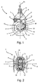
- Fig. 1 and 2 discloses a slide valve 1 comprising a housing 2 defining a passage way 3 for a fluid to flow through the housing 2 in an axial direction A thereof.
- the housing 2 has flanges 4, 5 for installing the valve in a pipeline system (not shown) for liquid or gaseous media.
- the housing 2 further comprises a top flange 6 for attaching a valve bonnet 7 with a valve box 8 through which a stem 9 passes from the outside of the valve 1 to the inside thereof.
- Rotating the stem around its longitudinal axis actuates a valve wedge 10 by engaging a valve wedge nut 11 of the valve wedge 10 so that the valve wedge 10 is moved up and down relative to the passage way.
- the movement of the valve wedge 10 is guided by guiding means comprising guide grooves 12 in the housing interacting with guide members 20 of the wedge to form a sliding bearing for a linear translational movement of the valve wedge 10 in a first direction T1 being the axial direction of the wedge and the stem.
- the guide grooves are essential parallel to the first direction T1 and are arranged on the inside of the housing 2 and lateral of the passage way 3.
- Two guide members 20 are provided on the periphery of the valve wedge 10 projecting in an outward direction from opposite sides thereof.
- the valve wedge 10 comprises a valve wedge core 13 made of cast iron encapsulated by a soft sealing material 50 such as rubber.
- the core 13 comprises sideways projecting ribs 17.
- a trough-shaped slide shoe 23 is arranged on each of the ribs 17 as will be described in more detail below.
- the projecting ribs with the slide shoes 23 arranged thereon comprise together with adjacent encapsulation the guide members 20.
- each projecting rib 17 is on each lateral side thereof provided with two mutually spaced projections 16 projecting from adjacent areas of the respective rib.
- An edge 18 being formed between each projection 16 and the adjacent lateral portions of the ribs.
- the lateral outer surfaces of each projection 16 are finished lateral surfaces 19.
- Opposite finished surfaces being finished so as to improve the tolerance of the spacing S between the opposite lateral finished surfaces. Further, it should be mentioned that the finished surfaces on the same side of the rib are lying in a common plane.
- each of the opposite ends of the ribs is provided with two end projections 24 with finished end faces 21.
- the end faces 21 of each rib being arranged in a common plane.
- the finished lateral faces 19 and finished end faces 21 of the ribs 17 are intended to cooperate with corresponding faces of the respective trough-shaped slide shoes 23.
- the slide shoes are prefabricated shoes and preferably injection moulded of a plastic material having high wear-resistance.
- An embodiment of a trough-shaped slide shoe 23 is shown in Fig. 4 .
- Each shoe 23 comprises opposite lateral side walls 22 and opposite end walls 25 and a bottom wall 26. Opposite inner surfaces 27 of the side walls 22 is spaced L corresponding to the spacing S between lateral finished surfaces of the ribs.
- a ledge 29 is provided at the upper rim 28 of the shoe.
- the shoes are arranged on the ribs by means of a friction snap fit engagement, whereby the ledges 29 are engaged behind the edges 18 of the projections 16 of the ribs and the opposite inner surfaces 27 of the shoe 23 engages the respective lateral finished surfaces 19 of the ribs as it more clearly appears from Figs. 6 and 7 .
- Each shoe 23 is provided with a limited weakened area 14, especially a small round area in the bottom wall 26.
- the weakened area 14 is broken due to the high injection pressure, whereby a vent opening is formed allowing air trapped between the rib 17 of the core and the shoe 23 to be vented through the formed vent opening.
- the weakened area 14 allows for a complete priming of the inner surface of the shoe 23 before moulding and venting of entrapped air during moulding so as to obtain complete encapsulation behind the shoe 23.
- the encapsulating rubber material 50 covers the outer surface of the core 13. Additionally, encapsulating material 50 is present between the inner surface of the shoes 23 and the outer surface of the ribs 17. The encapsulating material extends onto the rim of the shoes so that the core is completely enclosed by the encapsulation 50 and the shoes 23. The engagement between the inner surfaces of the shoes and the finished lateral surfaces 19 of the ribs 17 provide for a rigid support of the slide shoes so that the slide shoes are not moveable or able to flex laterally relative to the core of the wedge. Thereby, an excellent and precise guidance of the wedge is provided.
- the end projections 24 of the ribs have finished end surfaces 21.
- the end surfaces 21 of the ribs are mutually spaced at distance X.
- the tolerance of the distance between the opposite lateral faces of the ribs of the core and the mutual spacing between the opposite end faces 30 is preferably less than +/- 0.3 mm, especially less than +/- 0.2 mm in order to obtain the desired precision of the encapsulation 50 of the wedge and the wedge in general.
- the wedge is provided with a through-going axial bore 15 extending from an upper to a lower end of the wedge.
- a bushing 31 of brass or bronze is fixed to an upper end of the bore.
- the bushing is provided with an inner thread adapted to cooperate with an outer thread of the stem 9. Further, as seen in Fig. 4 , 6 and 7 the outer surfaces of the shoes are chambered between the lateral side walls 22 and the bottom wall 26 and rounded between the bottom wall 26 and the end walls 25.
- valve wedge can be manufactured by a method comprising the following steps:
- the lower surface 36 of the bushing is arranged on the upper support face 35, whereby the spacing Y between the upper support face 35 and the lower support face of the press-tool corresponds to the desired predetermined spacing between the lower surface of the bushing and the lower surface of the core.
- a conical mantel 38 is moved into the bore 39 of the bushing, whereby the bushing is expanded and the outer surface thereof pressed into recesses between protruding portions of the inner surface of the bore is of the core 13 so as to fixedly attach the bushing to the core.
- Each slide shoe 23 has two opposite lateral side walls 22 with the respective inner surfaces 27, a bottom wall 26 and two opposite end walls 25.
- the inner surfaces 27 of the lateral side walls are spaced so as to tightly engage the finished surfaces of the ribs 19 when the shoes 23 are arranged on the ribs.
- the inner surfaces of the shoes 23 are provided with an adhesive primer up to and including the rim 28 of the shoes 23 in order to thereby improve the connection between the shoes and the coating, which is to be injected in a tool at a later stage.
- the outer surface of the core 13 is primed with an adhesive primer in order to improve the adhesive between the core 13 and the injected rubber material.
- a slide shoe 23 is arranged on each rib 14 by a snap action and thereby laterally rigidly connected to the respective rib.
- a mould for moulding the rubber coating onto the core is provided, the mould having an inner surface area adapted to tightly abut the lateral outer surfaces of the shoes and thereby exactly position the shoes and therefore the core laterally.
- a mould 49 for moulding the coating onto the core is shown in Figs. 10-12 .
- the mould comprises an upper mould part 43, a lower mould part 44 and a middle mould part 45.
- the middle mould part comprises a mantel 46 adapted to be received in the bore of the bushing and thereby assist in positioning the core in the mould cavity.
- the mantel 46 is provided with a shoulder 47 adapted to engage the lower surface of the bushing, which is forced against said shoulder, whereby a precise longitudinal position of the core is provided.
- the lower mould part is as seen in Fig. 11 provided with inner surface areas 48 forming portion of the cavity and being adapted to tightly abut the corresponding outer surface of the lateral side wall of the respective shoe.
- the upper mould part is provided with inner surface areas (not shown) forming a portion of the mould cavity and being adapted to tightly abut the other lateral surface of the shoe in question, whereby the said inner surface areas 48 exactly position the shoe and thereby the core laterally.
- inner surface areas 48 exactly position the shoe and thereby the core laterally.
- rubber is injected into the mould in order to provide the coating thereof, whereby rubber is also provided in areas between the inner surface of the shoes 23 and the outer surface of the ribs, whereby the slide shoes 23 are firmly and rigidly connected to the core by vulcanization of the rubber.
- the coated wedge is removed from the mould and placed in a valve housing, an inner thread being provided in the bushing prior to moulding of the coating onto the core.
Landscapes
- Engineering & Computer Science (AREA)
- General Engineering & Computer Science (AREA)
- Mechanical Engineering (AREA)
- Manufacturing & Machinery (AREA)
- Moulds For Moulding Plastics Or The Like (AREA)
- Valve Housings (AREA)
- Sliding Valves (AREA)
- Casting Or Compression Moulding Of Plastics Or The Like (AREA)
- Devices For Conveying Motion By Means Of Endless Flexible Members (AREA)
- Clamps And Clips (AREA)
Description
- The present invention relates to the technical field of slide valves and in particular to a valve wedge for a slide valve comprising a rough cast metal wedge for a slide valve comprising a rough cast metal wedge core encapsulated in, i.e. coated with, a soft seal encapsulation, i.e. a soft coating, and having two guide members projecting transversely in opposite directions and being adapted to engage respective one of guide grooves provided inside a housing of the slide valve so as to take up an axial pressure exerted on the valve wedge during operation, each of said guide members comprising a sideways projecting rib of said rough cast wedge core and a prefabricated wear and corrosion-resistant slide shoe arranged thereon, each rib comprising laterally opposite lateral surfaces and an end-face and each shoe comprising two opposite lateral walls with inner surfaces and outer surfaces adapted for interacting with corresponding slide surfaces of the guide grooves and each shoe being fixedly connected with or vulcanized to the respective one of the ribs by means of soft seal encapsulation present between the rough cast wedge core and the shoe.
- Additionally, the present invention relates to a slide valve comprising a valve wedge according to the invention and to a method for manufacturing a valve wedge according to the invention.
- Slide valves may be used in pipeline systems for distributing and/or handling fluid such as water, sewages, natural gas or similar liquid or gaseous media. A slide valve comprises a housing defining a passage way for the fluid to flow in an axial direction to the housing. The passage may be closed and open by sliding the valve wedge in a direction transverse to the axial direction. Typically, the plane of the sliding movement of the valve wedge is essentially perpendicular to the axial direction. The motion of the valve wedge is actuated by actuation means. The actuation means may comprise a threaded valve stem configured to act upon a valve nut to produce a linear translational movement of the sliding of the slide wedge into or out of the passage way of the housing.
- Under operation, the valve wedge is subjected to considerable pressure in the axial direction. In order to take up these axial pressures sliding bearings comprising the guide members projecting into the corresponding guide grooves in the valve housing are provided. The guide grooves are shaped complimentary to the shape of the guide members so as to provide guidance at least in axial direction.
- In a slide valve in a soft sealing type, a sealing is provided by the soft sealing material, typically a rubber material, engaging a valve seat, which may be a dedicated valve seal element or simply a wall of the valve housing. The material of the core of the valve wedge is typically cast iron, which is prone to degradation/corrosion when exposed to a fluid passing through the valve. Therefore, the soft sealing encapsulation is provided for purposes of improving corrosion protection of the core. The ribs of the core may also be covered with the soft sealing material. However, the problem of such a solution is that the soft sealing material is typically not wear-resistant with respect to a sliding motion. Further, typical soft sealing material has a high friction coefficient with respect to most surfaces. This problem may be solved by using slide shoes arranged on the guide ribs, wherein the slide shoes are preferably made of a wear-resistant and corrosion-resistant material providing a low friction sliding interface with a sliding surface of a cooperating guide groove.
-
EP0171693 discloses a slide valve with a valve wedge comprising guide shoes that are attached to the valve wedge core and moulded together with a rubber encapsulation of the valve wedge. The problem with this solution is that the slide shoes, which are supported by a relatively thick, soft layer of soft seal material, prevent a precise control over the valve member movement as the slide shoes may flex laterally relative to the core, whereby the life of the valve wedge may be decreased. -
EP0926410 discloses a slide valve wedge, wherein a slide shoe is attached to the ribs of the core after the soft sealing encapsulation has been moulded onto the core. The problem with this solution is that the slide shoes supported by the soft layer prevent a precise control over the valve wedge movement as the guide shoes may flex laterally. In particular under large axial pressure on the valve wedge such flexing on the shoes may result in an excessive wear of the valve actuation mechanism as well as the sealing surfaces. Furthermore, when applying a soft seal encapsulation to a valve wedge, the valve wedge core is typically supported by centering pins during moulding in order to centre the core in the mould. These centering pins leave openings in the soft seal encapsulation, thus requiring a subsequent sealing step for these openings. -
DE3345133 discloses a valve wedge for a slide valve comprising a metal core encapsulated in a rubber elastic material. The metal core is provided with lateral guiding grooves in each of which a U-shaped sliding shoe of plastic material is arranged so that hollow space is formed between the sliding shoes and the guiding grooves. The gap or hollow space is filled with moulding mass of rubber elastic material during moulding of the encapsulation onto the metal core. The sliding shoes are supported by the soft rubber elastic material preventing a precise control over the valve wedge movement, especially at the large axial pressures on the valve wedge. - From
WO 2004/038266 A1 it is known to encapsulate a cast metal core of a valve wedge in a soft seal. However, it is difficult to ensure sufficient lateral rigidity when used in a slide valve. - The object of the present invention is to overcome at least some of the above-mentioned drawbacks and especially to provide a valve wedge that may be precisely guided relative to the housing of the slide valve and where the coating or encapsulation of the valve core may be controlled without using centering pins that decreases the corrosion resistance of the valve wedge.
- The valve wedge according to the invention is characterised in that the opposite outer lateral surfaces of the ribs are finished surfaces and that the opposite inner surfaces of each of the slide shoes is laterally rigidly supported by the corresponding outer lateral surfaces of the respective one of said ribs so that each rib laterally rigidly supports the respective one of the slide shoes. In other words, each opposite lateral face of each rib is rigidly connected with and thereby rigidly supports the corresponding inner surfaces of the lateral walls of the respective one of the slide shoes, whereby the slide shoes are laterally rigidly supported by the ribs so that the shoes are not laterally moveable or may flex laterally relative to the core. The prefabricated slide shoes provided on the ribs facilitates manufacturing of the valve wedge by positioning and centering the valve core in the mould during moulding of the soft seal encapsulation onto the core.
- By the finishing, the lateral outer surfaces of the ribs are subjected to additional processing after the core has been formed by casting. The finishing can be carried out by a mass-reducing process, i.e. where material is removed by machining. Another possibility is to carry out the finishing by means of a mass-conserving process such as stamping, where material is subjected to deformation. Finishing of the lateral surfaces improves the tolerance of the dimension between the opposite lateral surfaces of the ribs of the core so as to improve the tolerance of the moulding of the encapsulation and thereby improve the tolerance of the valve wedge.
- Further, the rigid support of the slide shoes directly on the respective ribs prevents any lateral movement of the core relative to the shoes and thereby provides an exact guidance of the slide surfaces of the shoe in the corresponding grooves in the housing. Due to the above rigid connection, encapsulation material present between the shoes and the core are not subjected to fatigue, whereby the life of the wedge is improved.
- According to an embodiment of the valve wedge, the slide shoes are made of a material with a relatively larger elastic modulus compared to that of the material of the soft seal encapsulation.
- By selection a slide shoe material that is relatively stiff, as compared to the soft seal encapsulation material, the stability of the slide shoe is improved and precision of the slide shoe operation increased. This is particularly advantageous when moving the valve wedge under a significant one-sided pressure load due to the pressure drop across the valve. Thereby, an enhanced durability and reliability of the valve wedge and the slide valve comprising such a valve wedge is achieved.
- According to an embodiment, the slide shoes are essentially U-shaped in a cross-sectional view and provided with a bottom face on a bottom wall extending between the lateral walls.
- The material of the slide shoes can be PA6.6 or POM. However, other plastic materials may be used having good sliding properties, high wear resistance and heat resistance. Preferably, the slide shoes are formed by injecting moulding.
- The material of the encapsulation can be EPDM for fluid and NBR for gases. However, other properties may also be used.
- The slide shoes may be trough-shaped and provided with opposite end walls with inner surfaces extending between the lateral walls. Thereby, the slide shoes circumferentially surround the respective ribs.
- According to an embodiment, the opposite inner surfaces of the shoes abut the corresponding lateral outer surfaces of the respective one of the ribs.
- Due to the very high injection pressure during injection moulding of the rubber coating onto the core, a very thin layer of rubber, i.e. rubber film, may be present between the outer lateral surfaces of the ribs of the core and the corresponding inner surfaces of the respective slide shoes. However, such a thin film is to be considered equivalent with a direct contact between the surfaces in question and thereby provide the desired rigid connection between the lateral surfaces of the ribs and the corresponding inner surfaces of the shoes.
- The shoe can be provided with a limited weakened area, especially a small round area in the bottom wall of the shoe, the weakening being such that during moulding of the encapsulation by injection of encapsulation material in the mould, the weakened area is broken due to the high injection pressure, whereby a vent opening is formed.
- The vent opening allows air trapped between the rib of the core and the shoe to be vented through the formed opening during moulding so as to obtain complete encapsulation behind the shoe. Further, the weakened area allows for complete priming of the inner surface of the shoe before moulding and prevents that primer is applied to the outer surface of the shoe.
- The tolerance of the dimension or distances between the opposite lateral faces of the ribs of the core is less than +/- 0.4 mm, preferably less than +/- 0.3 mm, especially less than +/- 0.2 mm.
- The slide shoes may be attached to the respective one of the ribs by snap fit-engagement.
- According to a further embodiment, the lateral surfaces of the ribs are laterally protruding surfaces, protruding relatively to the adjacent lateral portions of the rib, an edge being formed between the protruding surface and adjacent portion.
- The inner surface of each of the opposite lateral walls of the slide shoes may be provided with a ledge at the rim of the slide shoe opposite the bottom wall, said ledge being in engagement behind the above-mentioned edge.
- The outer surfaces of the slide shoes may be chamfered or rounded between the lateral walls and the bottom wall.
- Thereby, the positioning of the core in the mould is facilitated.
- Additionally, the outer surface of the slide shoes may be chamfered or rounded between the end walls and the bottom wall.
- Thereby, the arrangement of the core in the mould is further facilitated.
- The ribs core is preferably made of cast iron, especially SG-iron.
- The present invention further relates to slide valve comprising a valve wedge according to the invention.
- Additionally, the present invention relates to a method for manufacturing of a valve wedge according to the invention comprising the following steps:
- A: providing a rough cast core with sideways projecting ribs at opposite sides thereof, each rib having opposite lateral faces and an end face,
- B: subjecting each of the opposite surfaces of each rib for a finishing process so as to improve the tolerance of the spacing (S) between the lateral surfaces of the ribs,
- C: providing two slide shoes being essentially U-shaped as seen in a cross-sectional view and having two opposite lateral walls with respective inner surfaces and a bottom wall with an inner surface, the inner surfaces of the lateral walls of the slide shoes being spaced (L) so as to tightly engage the finished surfaces of the ribs,
- D: arrange a shoe on each rib so that it is laterally rigidly connected to the respective rib,
- E: providing a mould for moulding the rubber coating onto the core, the mould having inner surface areas adapted to tightly abut the lateral outer surfaces of the lateral side walls of the shoes and thereby exactly position the shoes and thereby the core laterally,
- F: injecting rubber into the mould in order to provide the coating thereof, whereby rubber is also provided in areas between the inner surface of the shoes and outer surfaces of the ribs, whereby the slide shoes are firmly and rigidly connected to the core by vulcanisation of the rubber, and
- G: remove the coated wedge from the mould.
- According to an embodiment of the method according to the invention, the outer lateral surfaces of the ribs are finished by stamping.
- The stamping may be provided so that the tolerance of the distance between the lateral surfaces of the ribs is less than +/- 0.4 mm, preferably less than +/- 0.3 mm, and especially less than +/- 0.2 mm.
- The finishing of the outer lateral surfaces may, as mentioned previously, also be carried out by machining, i.e. by removing material.
- According to a further embodiment prior to step D, the inner surfaces of the shoes are primed with an adhesive primer.
- Thereby, an improved connection between the shoes and the coating is provided.
- Further, prior to step D, the outer surface of the core may be primed with an adhesive primer.
- Thereby, an improved connection between the core and the rubber coating is provided.
- According to a further embodiment, prior to step D, the end faces of the ribs are finished so as to provide a predetermined dimension between the finished end faces.
- The tolerance between the predetermined dimension between the finished end surfaces of the core is preferably a narrow tolerance within fractional millimetres depending on the dimension such as less than +/- 0.4 mm, less than +/- 0.3 mm or less than +/-0.2 mm.
- The finished end surfaces may be provided by punching, whereby the punching advantageously is carried out at the same time as the lateral faces of the ribs are finished by stamping. However, it should be mentioned that both the finishing of the lateral faces and the end faces of the ribs may be carried out by other processes than the mentioned processes such as by machining removing material.
- Advantageously, the core is provided with a through-going axial bore extending from an upper to a lower end of the core. A brass or bronze bushing having an upper and a lower surface is fixedly connected in the bore at an upper end thereof. The bushing may be fixed to the upper end of the bore by a press fit provided by expanding the bushing by means of a drift so that outer surface portions of the bushing are pressed into recesses between protruding portions of the inner surfaces of the bore.
- Further, a predetermined longitudinal spacing between the lower surface and the bushing and the lower surface of the core may advantageously be provided.
- This can be done by machining the lower surface of the bushing to the desired tolerance on the predetermined spacing between the lower surface of the bushing and the lower surface of the core.
- Alternatively, a press-tool may be used comprising a lower support for supporting the lower end of the core and a tubular support extending upwardly from the lower support and ending in an upper support face for supporting the lower surface of the bushing during the expansion thereof. Thereby, the spacing between the lower support of the tool and the upper support face of the tubular support defines the predetermined spacing between the lower surface of the bushing and the lower surface of the core.
- Tolerance of the above predetermined spacing may be a narrow tolerance within fractional millimetres depending on the spacing such as less than +/- 0.4 mm, less than +/-0.3 mm, preferably less than +/- 0.2 mm.
- By means of the above predetermined longitudinal spacing, it is possible to obtain a precise longitudinal position of the core in the mould. Together with the mentioned precise and rigid support of the core in the mould by means of the shoes, it is possible to obtain a very precise position of the core in the mould and thereby obtain the desired thickness of the coating on the core over the entire extend thereof.
- In the following, the invention is further explained by reference to the drawings, in which:
-
Fig. 1 discloses a front elevational view of a slide valve partially cut away, -
Fig. 2 discloses a top elevational view of the slide valve ofFig. 1 with a valve bonnet removed, -
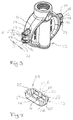
Fig. 3 discloses a perspective view of a valve core of a valve wedge according to the invention, -
Fig. 4 discloses a perspective view of a slide shoe for a valve wedge according to the invention, -
Fig.5 discloses a perspective view of a soft seal encapsulated valve wedge according to the invention, -
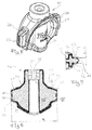
Fig. 6 discloses a longitudinal cross-sectional view of a valve wedge according to the invention, -
Fig. 7 discloses a sectional view along the line VII-VII inFig. 6 , -
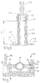
Fig. 8 discloses a sectional view of a press-tool for mounting a wedge nut in a wedge core, -
Fig. 9 discloses a cross-sectional view through a press- and punch-tool for finishing latter surfaces and end faces of the wedge core, -
Fig. 10 discloses diagrammatically a longitudinal sectional view through a mould for moulding a rubber elastic encapsulation onto the core, -
Fig. 11 discloses a lower mould part of the mould shown inFig. 10 as seen from above, -
Fig. 12 discloses the lower mould part seen in a sectional view with a wedge core arranged on a mantel of the middle part of the mould. -
Fig. 1 and 2 discloses aslide valve 1 comprising ahousing 2 defining apassage way 3 for a fluid to flow through thehousing 2 in an axial direction A thereof. Thehousing 2 hasflanges 4, 5 for installing the valve in a pipeline system (not shown) for liquid or gaseous media. Thehousing 2 further comprises atop flange 6 for attaching avalve bonnet 7 with avalve box 8 through which astem 9 passes from the outside of thevalve 1 to the inside thereof. Rotating the stem around its longitudinal axis actuates avalve wedge 10 by engaging avalve wedge nut 11 of thevalve wedge 10 so that thevalve wedge 10 is moved up and down relative to the passage way. The movement of thevalve wedge 10 is guided by guiding means comprisingguide grooves 12 in the housing interacting withguide members 20 of the wedge to form a sliding bearing for a linear translational movement of thevalve wedge 10 in a first direction T1 being the axial direction of the wedge and the stem. The guide grooves are essential parallel to the first direction T1 and are arranged on the inside of thehousing 2 and lateral of thepassage way 3. Twoguide members 20 are provided on the periphery of thevalve wedge 10 projecting in an outward direction from opposite sides thereof. - The
valve wedge 10 comprises avalve wedge core 13 made of cast iron encapsulated by asoft sealing material 50 such as rubber. Thecore 13 comprises sideways projectingribs 17. A trough-shapedslide shoe 23 is arranged on each of theribs 17 as will be described in more detail below. The projecting ribs with the slide shoes 23 arranged thereon comprise together with adjacent encapsulation theguide members 20. - As it more clearly appear from
Fig. 3 , each projectingrib 17 is on each lateral side thereof provided with two mutually spacedprojections 16 projecting from adjacent areas of the respective rib. Anedge 18 being formed between eachprojection 16 and the adjacent lateral portions of the ribs. The lateral outer surfaces of eachprojection 16 are finishedlateral surfaces 19. Opposite finished surfaces being finished so as to improve the tolerance of the spacing S between the opposite lateral finished surfaces. Further, it should be mentioned that the finished surfaces on the same side of the rib are lying in a common plane. - Additionally, each of the opposite ends of the ribs is provided with two
end projections 24 with finished end faces 21. The end faces 21 of each rib being arranged in a common plane. The finished lateral faces 19 and finished end faces 21 of theribs 17 are intended to cooperate with corresponding faces of the respective trough-shaped slide shoes 23. The slide shoes are prefabricated shoes and preferably injection moulded of a plastic material having high wear-resistance. An embodiment of a trough-shapedslide shoe 23 is shown inFig. 4 . Eachshoe 23 comprises oppositelateral side walls 22 andopposite end walls 25 and abottom wall 26. Oppositeinner surfaces 27 of theside walls 22 is spaced L corresponding to the spacing S between lateral finished surfaces of the ribs. At theupper rim 28 of the shoe aledge 29 is provided. The shoes are arranged on the ribs by means of a friction snap fit engagement, whereby theledges 29 are engaged behind theedges 18 of theprojections 16 of the ribs and the oppositeinner surfaces 27 of theshoe 23 engages the respective lateral finishedsurfaces 19 of the ribs as it more clearly appears fromFigs. 6 and 7 . - Each
shoe 23 is provided with a limited weakenedarea 14, especially a small round area in thebottom wall 26. During injection of the rubber into the mould, the weakenedarea 14 is broken due to the high injection pressure, whereby a vent opening is formed allowing air trapped between therib 17 of the core and theshoe 23 to be vented through the formed vent opening. The weakenedarea 14 allows for a complete priming of the inner surface of theshoe 23 before moulding and venting of entrapped air during moulding so as to obtain complete encapsulation behind theshoe 23. - As it can be seen from
Fig. 5, Fig. 6 and Fig. 7 , the encapsulatingrubber material 50 covers the outer surface of thecore 13. Additionally, encapsulatingmaterial 50 is present between the inner surface of theshoes 23 and the outer surface of theribs 17. The encapsulating material extends onto the rim of the shoes so that the core is completely enclosed by theencapsulation 50 and theshoes 23. The engagement between the inner surfaces of the shoes and the finishedlateral surfaces 19 of theribs 17 provide for a rigid support of the slide shoes so that the slide shoes are not moveable or able to flex laterally relative to the core of the wedge. Thereby, an excellent and precise guidance of the wedge is provided. - The
end projections 24 of the ribs have finished end surfaces 21. The end surfaces 21 of the ribs are mutually spaced at distance X. The tolerance of the distance between the opposite lateral faces of the ribs of the core and the mutual spacing between the opposite end faces 30 is preferably less than +/- 0.3 mm, especially less than +/- 0.2 mm in order to obtain the desired precision of theencapsulation 50 of the wedge and the wedge in general. Further, and as it appears fromFig. 6 , the wedge is provided with a through-goingaxial bore 15 extending from an upper to a lower end of the wedge. Abushing 31 of brass or bronze is fixed to an upper end of the bore. In the finished wedge the bushing is provided with an inner thread adapted to cooperate with an outer thread of thestem 9. Further, as seen inFig. 4 ,6 and 7 the outer surfaces of the shoes are chambered between thelateral side walls 22 and thebottom wall 26 and rounded between thebottom wall 26 and theend walls 25. - The valve wedge can be manufactured by a method comprising the following steps:
- providing a rough cast core, especially a core made of cast iron, especially cast SG iron with sideways projecting
ribs 17 at opposite sides thereof, each rib having opposite lateral faces and an end face, - subjecting the opposite surfaces of each
rib 17 to a finishing process so as to improve the tolerance of the spacing between thelateral surfaces 19 of the ribs. Further, the end surfaces of the opposite ribs may be finished so as to provide improved tolerance of the spacing between thefinished end surfaces 21 of theribs 17. The finishing of the lateral faces of the ribs and the end faces of the ribs may be carried out by means of combined punching and stampingtool 30 as shown inFig. 9 . The tool comprises opposite stampingparts 40, 41 stamping the opposite projection means 16 of theribs 14 of the core 13 so as to provide the desired tolerance of the spacing between the finishedlateral surfaces 19 of the projections of the ribs. Additionally, the tool comprises a punchingpart 42 punching, i.e. cutting, the end faces of the ribs so as to providefinished end surfaces 21 and thereby the desired spacing X between the said finished end surface of theribs 14. - providing a
bushing 31 of bronze having abore 39 and expanding thebushing 31 radially at the upper end of the through-going axial bore using a press-tool 32 as shown inFig. 8 . The shown press-tool comprises alower support 33 for supporting a lower end of the core and atubular support 34 extending upwardly from thelower support 33 and ending in anupper support face 35. - The
lower surface 36 of the bushing is arranged on theupper support face 35, whereby the spacing Y between theupper support face 35 and the lower support face of the press-tool corresponds to the desired predetermined spacing between the lower surface of the bushing and the lower surface of the core. - Thereafter, a
conical mantel 38 is moved into thebore 39 of the bushing, whereby the bushing is expanded and the outer surface thereof pressed into recesses between protruding portions of the inner surface of the bore is of the core 13 so as to fixedly attach the bushing to the core. - By means of the above predetermined longitudinal spacing Y between the lower surface of the bushing and the lower surface of the core, it is possible to obtain a precise longitudinal position of the core in the mould.
- Then two prefabricated injection moulded
slide shoes 23 being essentially trough-shaped are provided. Eachslide shoe 23 has two oppositelateral side walls 22 with the respectiveinner surfaces 27, abottom wall 26 and twoopposite end walls 25. Theinner surfaces 27 of the lateral side walls are spaced so as to tightly engage the finished surfaces of theribs 19 when theshoes 23 are arranged on the ribs. The inner surfaces of theshoes 23 are provided with an adhesive primer up to and including therim 28 of theshoes 23 in order to thereby improve the connection between the shoes and the coating, which is to be injected in a tool at a later stage. - Correspondingly, the outer surface of the
core 13 is primed with an adhesive primer in order to improve the adhesive between the core 13 and the injected rubber material. - Thereafter, a
slide shoe 23 is arranged on eachrib 14 by a snap action and thereby laterally rigidly connected to the respective rib. - A mould for moulding the rubber coating onto the core is provided, the mould having an inner surface area adapted to tightly abut the lateral outer surfaces of the shoes and thereby exactly position the shoes and therefore the core laterally.
- A
mould 49 for moulding the coating onto the core is shown inFigs. 10-12 . The mould comprises anupper mould part 43, a lower mould part 44 and amiddle mould part 45. As seen inFig. 10 , the middle mould part comprises amantel 46 adapted to be received in the bore of the bushing and thereby assist in positioning the core in the mould cavity. Themantel 46 is provided with ashoulder 47 adapted to engage the lower surface of the bushing, which is forced against said shoulder, whereby a precise longitudinal position of the core is provided. The lower mould part is as seen inFig. 11 provided withinner surface areas 48 forming portion of the cavity and being adapted to tightly abut the corresponding outer surface of the lateral side wall of the respective shoe. Correspondingly, the upper mould part is provided with inner surface areas (not shown) forming a portion of the mould cavity and being adapted to tightly abut the other lateral surface of the shoe in question, whereby the saidinner surface areas 48 exactly position the shoe and thereby the core laterally. Together with the above-mentioned precise longitudinal position of the core provided by means of themantel 46, a very precise positioning of the core in the mould is obtained, whereby the desired thickness of the coating on the core is obtained over the entire extend thereof when coating material is injected into the cavity of the mould in the next step. In this next step, rubber is injected into the mould in order to provide the coating thereof, whereby rubber is also provided in areas between the inner surface of theshoes 23 and the outer surface of the ribs, whereby the slide shoes 23 are firmly and rigidly connected to the core by vulcanization of the rubber. - After the vulcanization of the rubber has taken place, the coated wedge is removed from the mould and placed in a valve housing, an inner thread being provided in the bushing prior to moulding of the coating onto the core.
-
- 1.
- Slide valve
- 2.
- Housing
- 3.
- Passage way
- 4,5.
- Flange
- 6.
- Top flange
- 7.
- Valve bonnet
- 8.
- Valve box
- 9.
- Stem
- 10.
- Valve wedge
- 11.
- Valve wedge nut
- 12.
- Guide grooves
- 13.
- Core
- 14.
- Weakened area
- 15.
- Bore
- 16.
- Projection
- 17.
- Projecting ribs
- 18.
- Edge
- 19.
- Finished lateral surfaces
- 20.
- Guide member
- 21.
- Finished end faces
- 22.
- Lateral side walls
- 23.
- Prefabricated slide shoes
- 24.
- End projections
- 25.
- Opposite end walls
- 26.
- Bottom wall
- 27.
- Opposite inner surfaces
- 28.
- Upper rim
- 29.
- Ledge
- 30.
- Stamping and punching tool
- 31.
- Bushing
- 32.
- press-tool
- 33.
- Lower support
- 34.
- Tubular support
- 35.
- Upper support face
- 36.
- Lower surface
- 37.
- Lower support face
- 38.
- Conical mantle
- 39.
- Bore of bushing
- 40.
- Stamping part
- 41.
- Stamping part
- 42.
- Punch part
- 43.
- Upper mould part
- 44.
- Lower mould part
- 45.
- Middle mould part
- 46.
- Mantel
- 47.
- Shoulder
- 48.
- Inner surface area of lower mould part
- 49.
- Mould
- 50.
- Soft coating (encapsulation)
- A
- Axial direction
- T1, T2
- Transverse directions
- S
- Spacing between lateral finished surfaces
- L
- Spacing between opposite inner side walls
- X
- Spacing between opposite end surfaces
- Y
- Spacing between lower surface of bushing and lower end of core
Claims (15)
- Valve wedge (11) for a slide valve (1) comprising a rough cast metal wedge core (13) encapsulated in, i.e. coated with, a soft seal encapsulation (50), i.e. a soft coating, and having two guide members (20) projecting transversely in opposite directions and being adapted to engage respective one of guide grooves (12) provided inside a housing of the slide valve so as to take up an axial pressure exerted on the valve wedge (11) during operation, each of said guide members (20) comprising a sideways projecting rib (17) of said rough cast wedge core and a prefabricated wear and corrosion-resistant slide shoe arranged thereon, each rib (17) comprising laterally opposite lateral surfaces (19) and an end-face (21) and each shoe comprising two opposite lateral walls (22) with inner surfaces (27) and outer surfaces adapted for interacting with corresponding slide surfaces of the guide grooves and each shoe (23) being fixedly connected with or vulcanized to the respective one of the ribs (17) by means of soft seal encapsulation (50) present between the rough cast wedge core (13) and the shoe (23), characterised in that outer lateral surfaces of the ribs are finished surfaces (19) and that the opposite inner surfaces (27) of each of the slide shoes (23) is laterally rigidly supported by the corresponding outer lateral surfaces (19) of the respective one of said ribs (17) so that each rib laterally rigidly supports the respective one of said slide shoes (23).
- Valve wedge according to claim 1, wherein the slide shoes (23) are made of a material with a relatively larger elastic modulus compared to that of the material of the soft seal encapsulation (50).
- Valve wedge according to claim 1 and/or claim 2, wherein the slide shoes (23) are essentially U-shaped in a cross-sectional view and provided with a bottom face on a bottom wall (26) extending between the lateral walls (22).
- Valve wedge according to any of the preceding claims, wherein the slide shoes (23) are trough-shaped and provided with opposite end walls (25) with inner surfaces extending between the lateral walls (22).
- Valve wedge according to any of the preceding claims, wherein the opposite inner surfaces (27) of the shoes (23) abut the corresponding lateral outer surfaces of the respective one of the ribs (17).
- Valve wedge according to any of the preceding claims, wherein the shoe is provided with a limited weakened area (14), especially a small round area in the bottom wall (26) of the shoe, the weakening being such that during moulding of the encapsulation by injection of encapsulation the weakened area is broken due to the injection pressure, whereby a vent opening is formed.
- Valve wedge according to any of the preceding claims, wherein tolerance of dimension S between the opposite lateral surfaces (19) of the ribs (17) of the core (13) is less than +/- 0.4 mm, preferably less than +/- 0.3mm, especially less than +/- 0.2mm.
- Valve wedge according to any of the preceding claims, wherein the slide shoes (23) are attached to the respective one of the ribs (17) by snap-fit engagement.
- Valve wedge according to any of the preceding claims, wherein the lateral surfaces (19) of the ribs (17) are laterally protruding surfaces, protruding relatively to the adjacent lateral portions of the rib (17), an edge (18) being formed between the protruding surface and adjacent portion.
- Valve wedge according to any of the preceding claims, wherein the outer surfaces of the slide shoes (23) are chamfered or rounded between the lateral walls (22) and the bottom wall (26).
- Method for manufacturing of a valve wedge (10) as stated in claim 1, comprising the following steps:A: providing a rough cast core (13) with sideways projecting ribs (17) at opposite sides thereof, each rib having opposite lateral faces and an end face,B: subjecting each of the opposite surfaces of each rib for a finishing process so as to improve the tolerance of the spacing (S) between the lateral surfaces (19) of the ribs (17),C: providing two slide shoes (23) being essentially U-shaped as seen in a cross-sectional view and having two opposite lateral walls (22) with respective inner surfaces (27) and a bottom wall (26) with an inner surface, the inner surfaces (27) of the lateral walls (22) of the slide shoes (23) being spaced (L) so as to tightly engage the finished surfaces (19) of the ribs (17),D: arrange a shoe (23) on each rib (23) so that it is laterally rigidly connected to the respective rib,E: providing a mould (49) for moulding the rubber coating (50) onto the core (13), the mould having inner surface areas adapted to tightly abut the lateral outer surfaces of the side wall (22) of the shoes (23) and thereby exactly position the shoes (23) and thereby the core (13) laterally,F: injecting rubber into the mould in order to provide the coating thereof, whereby rubber is also provided in areas between the inner surface of the shoes (23) and outer surfaces of the ribs (17), whereby the slide shoes (23) are firmly and rigidly connected to the core by vulcanisation of the rubber, andG: remove the coated wedge from the mould.
- Method according to claim 11, wherein the outer lateral faces (19) of the ribs (17) are finished by stamping.
- Method according to claim 11 and/or claim 12, wherein prior to step D, the inner surfaces of the shoes (23) are primed with an adhesive primer.
- Method according to any of the preceding claims 11-13, wherein prior to step D, the outer surface of the core (13) is primed with an adhesive primer.
- Method according to any of the preceding claims 11-14, wherein prior to step D, the end faces (21) of the ribs (17) are finished so as to provide a predetermined dimension X between the finished end faces.
Priority Applications (2)
| Application Number | Priority Date | Filing Date | Title |
|---|---|---|---|
| HRP20161518TT HRP20161518T1 (en) | 2012-12-21 | 2013-12-20 | VALVE VALVE CLUTCH |
| EP13811237.0A EP2935955B1 (en) | 2012-12-21 | 2013-12-20 | Valve wedge for a slide valve |
Applications Claiming Priority (3)
| Application Number | Priority Date | Filing Date | Title |
|---|---|---|---|
| EP12198999.0A EP2746629A1 (en) | 2012-12-21 | 2012-12-21 | Valve wedge for a slide valve |
| EP13811237.0A EP2935955B1 (en) | 2012-12-21 | 2013-12-20 | Valve wedge for a slide valve |
| PCT/EP2013/077609 WO2014096322A1 (en) | 2012-12-21 | 2013-12-20 | Valve wedge for a slide valve |
Publications (2)
| Publication Number | Publication Date |
|---|---|
| EP2935955A1 EP2935955A1 (en) | 2015-10-28 |
| EP2935955B1 true EP2935955B1 (en) | 2016-10-19 |
Family
ID=47520791
Family Applications (2)
| Application Number | Title | Priority Date | Filing Date |
|---|---|---|---|
| EP12198999.0A Withdrawn EP2746629A1 (en) | 2012-12-21 | 2012-12-21 | Valve wedge for a slide valve |
| EP13811237.0A Active EP2935955B1 (en) | 2012-12-21 | 2013-12-20 | Valve wedge for a slide valve |
Family Applications Before (1)
| Application Number | Title | Priority Date | Filing Date |
|---|---|---|---|
| EP12198999.0A Withdrawn EP2746629A1 (en) | 2012-12-21 | 2012-12-21 | Valve wedge for a slide valve |
Country Status (14)
| Country | Link |
|---|---|
| US (1) | US9995401B2 (en) |
| EP (2) | EP2746629A1 (en) |
| JP (1) | JP6423359B2 (en) |
| KR (1) | KR20150097593A (en) |
| CN (1) | CN104854385B (en) |
| AU (1) | AU2013366594B2 (en) |
| BR (1) | BR112015014576A2 (en) |
| DK (1) | DK2935955T3 (en) |
| ES (1) | ES2604655T3 (en) |
| HR (1) | HRP20161518T1 (en) |
| PL (1) | PL2935955T3 (en) |
| PT (1) | PT2935955T (en) |
| WO (1) | WO2014096322A1 (en) |
| ZA (1) | ZA201503739B (en) |
Cited By (1)
| Publication number | Priority date | Publication date | Assignee | Title |
|---|---|---|---|---|
| WO2023031812A1 (en) * | 2021-08-31 | 2023-03-09 | Fucoli Somepal - Fundição De Ferro S.A. | Valve gate for a slide valve |
Families Citing this family (3)
| Publication number | Priority date | Publication date | Assignee | Title |
|---|---|---|---|---|
| US9845890B2 (en) * | 2016-01-11 | 2017-12-19 | Valterra Products, Llc | Gate valve for controlling the passage of liquid |
| US11226042B1 (en) * | 2020-09-30 | 2022-01-18 | Kennedy Valve Company | Gate valve |
| EP4656912A3 (en) * | 2022-05-18 | 2026-05-20 | Pittway Sarl | GAS FLOW ADJUSTING DEVICE FOR A GAS BURNER APPLIANCE AND GAS BURNER APPLIANCE |
Family Cites Families (10)
| Publication number | Priority date | Publication date | Assignee | Title |
|---|---|---|---|---|
| DE3345133A1 (en) | 1983-12-14 | 1985-09-26 | Bopp & Reuther Gmbh, 6800 Mannheim | LOCKING WEDGE FOR LOCKING VALVES |
| DE3428485A1 (en) | 1984-08-02 | 1986-02-20 | Bopp & Reuther Gmbh, 6800 Mannheim | LOCKING WEDGE FOR LOCKING VALVES |
| CN85101818A (en) | 1985-04-01 | 1987-01-10 | 姆登扬科雄 | Wedge slide valve |
| US5052427A (en) * | 1990-06-14 | 1991-10-01 | Spinsafe, Inc. | Method and apparatus to facilitate the injection of sealant into a pressurized fluid member |
| AT405758B (en) | 1997-12-15 | 1999-11-25 | Hawle & Co E | SLIDING VALVE |
| FR2846392B1 (en) * | 2002-10-23 | 2005-09-02 | Saint Gobain Pont A Mousson | STOP CORNER, AND CORRESPONDING STOP VALVE |
| DE102008038971A1 (en) | 2008-08-13 | 2010-02-18 | Robert Bosch Gmbh | Valve spool valves and method of manufacture |
| MY154106A (en) | 2009-02-10 | 2015-04-30 | Tyco Valves & Controls Lp | Gate valve with integrated support members |
| JP5253269B2 (en) | 2009-03-31 | 2013-07-31 | 株式会社クボタ | Gate valve |
| CN201687971U (en) | 2009-11-30 | 2010-12-29 | 南通龙源电站阀门有限公司 | Wedge-type gate valve |
-
2012
- 2012-12-21 EP EP12198999.0A patent/EP2746629A1/en not_active Withdrawn
-
2013
- 2013-12-20 PL PL13811237T patent/PL2935955T3/en unknown
- 2013-12-20 CN CN201380065099.7A patent/CN104854385B/en not_active Expired - Fee Related
- 2013-12-20 PT PT138112370T patent/PT2935955T/en unknown
- 2013-12-20 AU AU2013366594A patent/AU2013366594B2/en not_active Ceased
- 2013-12-20 DK DK13811237.0T patent/DK2935955T3/en active
- 2013-12-20 US US14/651,511 patent/US9995401B2/en not_active Expired - Fee Related
- 2013-12-20 ES ES13811237.0T patent/ES2604655T3/en active Active
- 2013-12-20 HR HRP20161518TT patent/HRP20161518T1/en unknown
- 2013-12-20 EP EP13811237.0A patent/EP2935955B1/en active Active
- 2013-12-20 JP JP2015548624A patent/JP6423359B2/en not_active Expired - Fee Related
- 2013-12-20 KR KR1020157018396A patent/KR20150097593A/en not_active Withdrawn
- 2013-12-20 WO PCT/EP2013/077609 patent/WO2014096322A1/en not_active Ceased
- 2013-12-20 BR BR112015014576A patent/BR112015014576A2/en not_active Application Discontinuation
-
2015
- 2015-05-26 ZA ZA2015/03739A patent/ZA201503739B/en unknown
Cited By (1)
| Publication number | Priority date | Publication date | Assignee | Title |
|---|---|---|---|---|
| WO2023031812A1 (en) * | 2021-08-31 | 2023-03-09 | Fucoli Somepal - Fundição De Ferro S.A. | Valve gate for a slide valve |
Also Published As
| Publication number | Publication date |
|---|---|
| AU2013366594B2 (en) | 2018-03-15 |
| HRP20161518T1 (en) | 2017-01-13 |
| US20150323084A1 (en) | 2015-11-12 |
| WO2014096322A1 (en) | 2014-06-26 |
| EP2935955A1 (en) | 2015-10-28 |
| PT2935955T (en) | 2016-11-30 |
| PL2935955T3 (en) | 2017-02-28 |
| ZA201503739B (en) | 2016-07-27 |
| US9995401B2 (en) | 2018-06-12 |
| EP2746629A1 (en) | 2014-06-25 |
| CN104854385A (en) | 2015-08-19 |
| HK1211335A1 (en) | 2016-05-20 |
| DK2935955T3 (en) | 2017-01-09 |
| AU2013366594A1 (en) | 2015-07-09 |
| JP2016502052A (en) | 2016-01-21 |
| KR20150097593A (en) | 2015-08-26 |
| JP6423359B2 (en) | 2018-11-14 |
| CN104854385B (en) | 2017-07-18 |
| BR112015014576A2 (en) | 2018-04-24 |
| ES2604655T3 (en) | 2017-03-08 |
Similar Documents
| Publication | Publication Date | Title |
|---|---|---|
| US5743169A (en) | Diaphragm assembly and method of manufacturing same | |
| US9995401B2 (en) | Valve wedge for a slide valve | |
| KR101833509B1 (en) | Gasket assembly with improved locating and retention pin and method of construction thereof | |
| US10989310B2 (en) | Insertion of butterfly valve without disrupting flow | |
| US9067346B2 (en) | Seal and procedure for its production | |
| CN108386554B (en) | Control Valves with Integral Trim | |
| JPS60179576A (en) | Wedge shaped valve body for slide type partition valve, its production and injection mold for producing said wedge shaped valve body | |
| TWI638107B (en) | Valve heart | |
| WO2018189424A1 (en) | Valve insert and air venting valve | |
| US10883608B2 (en) | Disc brake and piston boot | |
| RU2304246C2 (en) | Valve | |
| KR20160003625A (en) | Wax actuator with high cycle life | |
| RU2657399C2 (en) | Spring gasket for valve housing | |
| KR20210058710A (en) | Fluid pump | |
| KR20190012223A (en) | Method for manufacturing grooved and grooved ring seals | |
| JP7223687B2 (en) | Solenoid valve for controlling the brake pressure of the wheel brake | |
| HK1211335B (en) | Valve wedge for a slide valve | |
| JP2009264415A (en) | Valve stem seal mounting structure | |
| KR20210045480A (en) | valve | |
| KR20240010017A (en) | Cocks for valves and valves containing such cocks | |
| US20080098886A1 (en) | Piston assembly and method of manufacturing piston assembly | |
| JP2009068672A (en) | Sealing device, and its manufacturing method | |
| JP6463890B2 (en) | Ring mold type boot and manufacturing method thereof | |
| EP4396478A1 (en) | Valve gate for a slide valve |
Legal Events
| Date | Code | Title | Description |
|---|---|---|---|
| PUAI | Public reference made under article 153(3) epc to a published international application that has entered the european phase |
Free format text: ORIGINAL CODE: 0009012 |
|
| 17P | Request for examination filed |
Effective date: 20150608 |
|
| AK | Designated contracting states |
Kind code of ref document: A1 Designated state(s): AL AT BE BG CH CY CZ DE DK EE ES FI FR GB GR HR HU IE IS IT LI LT LU LV MC MK MT NL NO PL PT RO RS SE SI SK SM TR |
|
| AX | Request for extension of the european patent |
Extension state: BA ME |
|
| GRAP | Despatch of communication of intention to grant a patent |
Free format text: ORIGINAL CODE: EPIDOSNIGR1 |
|
| RIN1 | Information on inventor provided before grant (corrected) |
Inventor name: WINTHER, THOMAS |
|
| INTG | Intention to grant announced |
Effective date: 20160609 |
|
| GRAS | Grant fee paid |
Free format text: ORIGINAL CODE: EPIDOSNIGR3 |
|
| GRAA | (expected) grant |
Free format text: ORIGINAL CODE: 0009210 |
|
| AK | Designated contracting states |
Kind code of ref document: B1 Designated state(s): AL AT BE BG CH CY CZ DE DK EE ES FI FR GB GR HR HU IE IS IT LI LT LU LV MC MK MT NL NO PL PT RO RS SE SI SK SM TR |
|
| AX | Request for extension of the european patent |
Extension state: BA ME |
|
| REG | Reference to a national code |
Ref country code: GB Ref legal event code: FG4D |
|
| REG | Reference to a national code |
Ref country code: CH Ref legal event code: EP |
|
| REG | Reference to a national code |
Ref country code: AT Ref legal event code: REF Ref document number: 838643 Country of ref document: AT Kind code of ref document: T Effective date: 20161115 |
|
| REG | Reference to a national code |
Ref country code: IE Ref legal event code: FG4D |
|
| REG | Reference to a national code |
Ref country code: HR Ref legal event code: TUEP Ref document number: P20161518 Country of ref document: HR |
|
| REG | Reference to a national code |
Ref country code: NL Ref legal event code: FP Ref country code: PT Ref legal event code: SC4A Ref document number: 2935955 Country of ref document: PT Date of ref document: 20161130 Kind code of ref document: T Free format text: AVAILABILITY OF NATIONAL TRANSLATION Effective date: 20161118 |
|
| REG | Reference to a national code |
Ref country code: DE Ref legal event code: R096 Ref document number: 602013013080 Country of ref document: DE |
|
| REG | Reference to a national code |
Ref country code: SE Ref legal event code: TRGR |
|
| REG | Reference to a national code |
Ref country code: FR Ref legal event code: PLFP Year of fee payment: 4 |
|
| REG | Reference to a national code |
Ref country code: DK Ref legal event code: T3 Effective date: 20170103 |
|
| REG | Reference to a national code |
Ref country code: HR Ref legal event code: T1PR Ref document number: P20161518 Country of ref document: HR |
|
| REG | Reference to a national code |
Ref country code: NO Ref legal event code: T2 Effective date: 20161019 |
|
| REG | Reference to a national code |
Ref country code: LT Ref legal event code: MG4D |
|
| PG25 | Lapsed in a contracting state [announced via postgrant information from national office to epo] |
Ref country code: LV Free format text: LAPSE BECAUSE OF FAILURE TO SUBMIT A TRANSLATION OF THE DESCRIPTION OR TO PAY THE FEE WITHIN THE PRESCRIBED TIME-LIMIT Effective date: 20161019 |
|
| REG | Reference to a national code |
Ref country code: ES Ref legal event code: FG2A Ref document number: 2604655 Country of ref document: ES Kind code of ref document: T3 Effective date: 20170308 |
|
| PG25 | Lapsed in a contracting state [announced via postgrant information from national office to epo] |
Ref country code: LT Free format text: LAPSE BECAUSE OF FAILURE TO SUBMIT A TRANSLATION OF THE DESCRIPTION OR TO PAY THE FEE WITHIN THE PRESCRIBED TIME-LIMIT Effective date: 20161019 Ref country code: GR Free format text: LAPSE BECAUSE OF FAILURE TO SUBMIT A TRANSLATION OF THE DESCRIPTION OR TO PAY THE FEE WITHIN THE PRESCRIBED TIME-LIMIT Effective date: 20170120 |
|
| PG25 | Lapsed in a contracting state [announced via postgrant information from national office to epo] |
Ref country code: IS Free format text: LAPSE BECAUSE OF FAILURE TO SUBMIT A TRANSLATION OF THE DESCRIPTION OR TO PAY THE FEE WITHIN THE PRESCRIBED TIME-LIMIT Effective date: 20170219 Ref country code: RS Free format text: LAPSE BECAUSE OF FAILURE TO SUBMIT A TRANSLATION OF THE DESCRIPTION OR TO PAY THE FEE WITHIN THE PRESCRIBED TIME-LIMIT Effective date: 20161019 Ref country code: FI Free format text: LAPSE BECAUSE OF FAILURE TO SUBMIT A TRANSLATION OF THE DESCRIPTION OR TO PAY THE FEE WITHIN THE PRESCRIBED TIME-LIMIT Effective date: 20161019 |
|
| REG | Reference to a national code |
Ref country code: DE Ref legal event code: R097 Ref document number: 602013013080 Country of ref document: DE |
|
| PG25 | Lapsed in a contracting state [announced via postgrant information from national office to epo] |
Ref country code: RO Free format text: LAPSE BECAUSE OF FAILURE TO SUBMIT A TRANSLATION OF THE DESCRIPTION OR TO PAY THE FEE WITHIN THE PRESCRIBED TIME-LIMIT Effective date: 20161019 Ref country code: EE Free format text: LAPSE BECAUSE OF FAILURE TO SUBMIT A TRANSLATION OF THE DESCRIPTION OR TO PAY THE FEE WITHIN THE PRESCRIBED TIME-LIMIT Effective date: 20161019 Ref country code: SK Free format text: LAPSE BECAUSE OF FAILURE TO SUBMIT A TRANSLATION OF THE DESCRIPTION OR TO PAY THE FEE WITHIN THE PRESCRIBED TIME-LIMIT Effective date: 20161019 |
|
| REG | Reference to a national code |
Ref country code: CH Ref legal event code: PL |
|
| PLBE | No opposition filed within time limit |
Free format text: ORIGINAL CODE: 0009261 |
|
| STAA | Information on the status of an ep patent application or granted ep patent |
Free format text: STATUS: NO OPPOSITION FILED WITHIN TIME LIMIT |
|
| PG25 | Lapsed in a contracting state [announced via postgrant information from national office to epo] |
Ref country code: SM Free format text: LAPSE BECAUSE OF FAILURE TO SUBMIT A TRANSLATION OF THE DESCRIPTION OR TO PAY THE FEE WITHIN THE PRESCRIBED TIME-LIMIT Effective date: 20161019 Ref country code: BG Free format text: LAPSE BECAUSE OF FAILURE TO SUBMIT A TRANSLATION OF THE DESCRIPTION OR TO PAY THE FEE WITHIN THE PRESCRIBED TIME-LIMIT Effective date: 20170119 |
|
| 26N | No opposition filed |
Effective date: 20170720 |
|
| PG25 | Lapsed in a contracting state [announced via postgrant information from national office to epo] |
Ref country code: MC Free format text: LAPSE BECAUSE OF FAILURE TO SUBMIT A TRANSLATION OF THE DESCRIPTION OR TO PAY THE FEE WITHIN THE PRESCRIBED TIME-LIMIT Effective date: 20161019 |
|
| REG | Reference to a national code |
Ref country code: IE Ref legal event code: MM4A |
|
| PG25 | Lapsed in a contracting state [announced via postgrant information from national office to epo] |
Ref country code: LU Free format text: LAPSE BECAUSE OF NON-PAYMENT OF DUE FEES Effective date: 20161220 Ref country code: LI Free format text: LAPSE BECAUSE OF NON-PAYMENT OF DUE FEES Effective date: 20161231 Ref country code: CH Free format text: LAPSE BECAUSE OF NON-PAYMENT OF DUE FEES Effective date: 20161231 |
|
| PG25 | Lapsed in a contracting state [announced via postgrant information from national office to epo] |
Ref country code: SI Free format text: LAPSE BECAUSE OF FAILURE TO SUBMIT A TRANSLATION OF THE DESCRIPTION OR TO PAY THE FEE WITHIN THE PRESCRIBED TIME-LIMIT Effective date: 20161019 Ref country code: IE Free format text: LAPSE BECAUSE OF NON-PAYMENT OF DUE FEES Effective date: 20161220 |
|
| REG | Reference to a national code |
Ref country code: FR Ref legal event code: PLFP Year of fee payment: 5 |
|
| PGFP | Annual fee paid to national office [announced via postgrant information from national office to epo] |
Ref country code: PT Payment date: 20171220 Year of fee payment: 5 |
|
| PG25 | Lapsed in a contracting state [announced via postgrant information from national office to epo] |
Ref country code: HU Free format text: LAPSE BECAUSE OF FAILURE TO SUBMIT A TRANSLATION OF THE DESCRIPTION OR TO PAY THE FEE WITHIN THE PRESCRIBED TIME-LIMIT; INVALID AB INITIO Effective date: 20131220 |
|
| PG25 | Lapsed in a contracting state [announced via postgrant information from national office to epo] |
Ref country code: CY Free format text: LAPSE BECAUSE OF FAILURE TO SUBMIT A TRANSLATION OF THE DESCRIPTION OR TO PAY THE FEE WITHIN THE PRESCRIBED TIME-LIMIT Effective date: 20161019 Ref country code: MK Free format text: LAPSE BECAUSE OF FAILURE TO SUBMIT A TRANSLATION OF THE DESCRIPTION OR TO PAY THE FEE WITHIN THE PRESCRIBED TIME-LIMIT Effective date: 20161019 |
|
| PG25 | Lapsed in a contracting state [announced via postgrant information from national office to epo] |
Ref country code: MT Free format text: LAPSE BECAUSE OF NON-PAYMENT OF DUE FEES Effective date: 20161220 |
|
| REG | Reference to a national code |
Ref country code: HR Ref legal event code: ODRP Ref document number: P20161518 Country of ref document: HR Payment date: 20181214 Year of fee payment: 6 |
|
| PGFP | Annual fee paid to national office [announced via postgrant information from national office to epo] |
Ref country code: CZ Payment date: 20181214 Year of fee payment: 6 Ref country code: AT Payment date: 20181221 Year of fee payment: 6 Ref country code: DE Payment date: 20181218 Year of fee payment: 6 Ref country code: DK Payment date: 20181213 Year of fee payment: 6 Ref country code: NL Payment date: 20181231 Year of fee payment: 6 Ref country code: PL Payment date: 20181214 Year of fee payment: 6 |
|
| PGFP | Annual fee paid to national office [announced via postgrant information from national office to epo] |
Ref country code: HR Payment date: 20181214 Year of fee payment: 6 Ref country code: FR Payment date: 20181227 Year of fee payment: 6 Ref country code: GB Payment date: 20181219 Year of fee payment: 6 |
|
| REG | Reference to a national code |
Ref country code: AT Ref legal event code: UEP Ref document number: 838643 Country of ref document: AT Kind code of ref document: T Effective date: 20161019 |
|
| PGFP | Annual fee paid to national office [announced via postgrant information from national office to epo] |
Ref country code: IT Payment date: 20181220 Year of fee payment: 6 Ref country code: NO Payment date: 20181227 Year of fee payment: 6 Ref country code: ES Payment date: 20190102 Year of fee payment: 6 |
|
| PGFP | Annual fee paid to national office [announced via postgrant information from national office to epo] |
Ref country code: BE Payment date: 20181231 Year of fee payment: 6 Ref country code: SE Payment date: 20181228 Year of fee payment: 6 |
|
| REG | Reference to a national code |
Ref country code: HR Ref legal event code: PBON Ref document number: P20161518 Country of ref document: HR Effective date: 20191220 |
|
| REG | Reference to a national code |
Ref country code: DE Ref legal event code: R119 Ref document number: 602013013080 Country of ref document: DE |
|
| REG | Reference to a national code |
Ref country code: DK Ref legal event code: EBP Effective date: 20191231 Ref country code: NO Ref legal event code: MMEP |
|
| REG | Reference to a national code |
Ref country code: SE Ref legal event code: EUG |
|
| PG25 | Lapsed in a contracting state [announced via postgrant information from national office to epo] |
Ref country code: AL Free format text: LAPSE BECAUSE OF FAILURE TO SUBMIT A TRANSLATION OF THE DESCRIPTION OR TO PAY THE FEE WITHIN THE PRESCRIBED TIME-LIMIT Effective date: 20161019 Ref country code: CZ Free format text: LAPSE BECAUSE OF NON-PAYMENT OF DUE FEES Effective date: 20191220 |
|
| REG | Reference to a national code |
Ref country code: NL Ref legal event code: MM Effective date: 20200101 |
|
| REG | Reference to a national code |
Ref country code: AT Ref legal event code: MM01 Ref document number: 838643 Country of ref document: AT Kind code of ref document: T Effective date: 20191220 |
|
| REG | Reference to a national code |
Ref country code: BE Ref legal event code: MM Effective date: 20191231 |
|
| GBPC | Gb: european patent ceased through non-payment of renewal fee |
Effective date: 20191220 |
|
| PG25 | Lapsed in a contracting state [announced via postgrant information from national office to epo] |
Ref country code: NL Free format text: LAPSE BECAUSE OF NON-PAYMENT OF DUE FEES Effective date: 20200101 |
|
| PG25 | Lapsed in a contracting state [announced via postgrant information from national office to epo] |
Ref country code: IT Free format text: LAPSE BECAUSE OF NON-PAYMENT OF DUE FEES Effective date: 20191220 Ref country code: FR Free format text: LAPSE BECAUSE OF NON-PAYMENT OF DUE FEES Effective date: 20191231 Ref country code: GB Free format text: LAPSE BECAUSE OF NON-PAYMENT OF DUE FEES Effective date: 20191220 Ref country code: PT Free format text: LAPSE BECAUSE OF NON-PAYMENT OF DUE FEES Effective date: 20200723 Ref country code: NO Free format text: LAPSE BECAUSE OF NON-PAYMENT OF DUE FEES Effective date: 20191231 Ref country code: DE Free format text: LAPSE BECAUSE OF NON-PAYMENT OF DUE FEES Effective date: 20200701 Ref country code: SE Free format text: LAPSE BECAUSE OF NON-PAYMENT OF DUE FEES Effective date: 20191221 |
|
| PG25 | Lapsed in a contracting state [announced via postgrant information from national office to epo] |
Ref country code: AT Free format text: LAPSE BECAUSE OF NON-PAYMENT OF DUE FEES Effective date: 20191220 Ref country code: HR Free format text: LAPSE BECAUSE OF NON-PAYMENT OF DUE FEES Effective date: 20191220 Ref country code: BE Free format text: LAPSE BECAUSE OF NON-PAYMENT OF DUE FEES Effective date: 20191231 |
|
| PG25 | Lapsed in a contracting state [announced via postgrant information from national office to epo] |
Ref country code: DK Free format text: LAPSE BECAUSE OF NON-PAYMENT OF DUE FEES Effective date: 20191231 |
|
| REG | Reference to a national code |
Ref country code: ES Ref legal event code: FD2A Effective date: 20210525 |
|
| PG25 | Lapsed in a contracting state [announced via postgrant information from national office to epo] |
Ref country code: ES Free format text: LAPSE BECAUSE OF NON-PAYMENT OF DUE FEES Effective date: 20191221 |
|
| PG25 | Lapsed in a contracting state [announced via postgrant information from national office to epo] |
Ref country code: PL Free format text: LAPSE BECAUSE OF NON-PAYMENT OF DUE FEES Effective date: 20191220 |
|
| PG25 | Lapsed in a contracting state [announced via postgrant information from national office to epo] |
Ref country code: TR Free format text: LAPSE BECAUSE OF NON-PAYMENT OF DUE FEES Effective date: 20191220 |