EP2935837B1 - Joint d'étanchéité segmenté de turbine à gaz - Google Patents
Joint d'étanchéité segmenté de turbine à gaz Download PDFInfo
- Publication number
- EP2935837B1 EP2935837B1 EP13865215.1A EP13865215A EP2935837B1 EP 2935837 B1 EP2935837 B1 EP 2935837B1 EP 13865215 A EP13865215 A EP 13865215A EP 2935837 B1 EP2935837 B1 EP 2935837B1
- Authority
- EP
- European Patent Office
- Prior art keywords
- wall
- seal
- seal segment
- axial
- axial wall
- Prior art date
- Legal status (The legal status is an assumption and is not a legal conclusion. Google has not performed a legal analysis and makes no representation as to the accuracy of the status listed.)
- Active
Links
- 239000007789 gas Substances 0.000 description 39
- 230000000712 assembly Effects 0.000 description 19
- 238000000429 assembly Methods 0.000 description 19
- 238000001816 cooling Methods 0.000 description 6
- 239000000567 combustion gas Substances 0.000 description 5
- 239000000284 extract Substances 0.000 description 5
- 239000000446 fuel Substances 0.000 description 5
- 239000000956 alloy Substances 0.000 description 2
- 229910045601 alloy Inorganic materials 0.000 description 2
- 230000008901 benefit Effects 0.000 description 2
- 230000006835 compression Effects 0.000 description 2
- 238000007906 compression Methods 0.000 description 2
- 230000037406 food intake Effects 0.000 description 2
- 230000003068 static effect Effects 0.000 description 2
- OQPDWFJSZHWILH-UHFFFAOYSA-N [Al].[Al].[Al].[Ti] Chemical compound [Al].[Al].[Al].[Ti] OQPDWFJSZHWILH-UHFFFAOYSA-N 0.000 description 1
- 239000012809 cooling fluid Substances 0.000 description 1
- 210000003746 feather Anatomy 0.000 description 1
- 238000004519 manufacturing process Methods 0.000 description 1
- 239000000463 material Substances 0.000 description 1
- 238000012986 modification Methods 0.000 description 1
- 230000004048 modification Effects 0.000 description 1
- 238000007789 sealing Methods 0.000 description 1
- 229910021324 titanium aluminide Inorganic materials 0.000 description 1
Images


Classifications
-
- F—MECHANICAL ENGINEERING; LIGHTING; HEATING; WEAPONS; BLASTING
- F01—MACHINES OR ENGINES IN GENERAL; ENGINE PLANTS IN GENERAL; STEAM ENGINES
- F01D—NON-POSITIVE DISPLACEMENT MACHINES OR ENGINES, e.g. STEAM TURBINES
- F01D11/00—Preventing or minimising internal leakage of working-fluid, e.g. between stages
- F01D11/08—Preventing or minimising internal leakage of working-fluid, e.g. between stages for sealing space between rotor blade tips and stator
- F01D11/12—Preventing or minimising internal leakage of working-fluid, e.g. between stages for sealing space between rotor blade tips and stator using a rubstrip, e.g. erodible. deformable or resiliently-biased part
- F01D11/122—Preventing or minimising internal leakage of working-fluid, e.g. between stages for sealing space between rotor blade tips and stator using a rubstrip, e.g. erodible. deformable or resiliently-biased part with erodable or abradable material
-
- F—MECHANICAL ENGINEERING; LIGHTING; HEATING; WEAPONS; BLASTING
- F01—MACHINES OR ENGINES IN GENERAL; ENGINE PLANTS IN GENERAL; STEAM ENGINES
- F01D—NON-POSITIVE DISPLACEMENT MACHINES OR ENGINES, e.g. STEAM TURBINES
- F01D11/00—Preventing or minimising internal leakage of working-fluid, e.g. between stages
- F01D11/001—Preventing or minimising internal leakage of working-fluid, e.g. between stages for sealing space between stator blade and rotor
-
- F—MECHANICAL ENGINEERING; LIGHTING; HEATING; WEAPONS; BLASTING
- F01—MACHINES OR ENGINES IN GENERAL; ENGINE PLANTS IN GENERAL; STEAM ENGINES
- F01D—NON-POSITIVE DISPLACEMENT MACHINES OR ENGINES, e.g. STEAM TURBINES
- F01D11/00—Preventing or minimising internal leakage of working-fluid, e.g. between stages
- F01D11/005—Sealing means between non relatively rotating elements
- F01D11/006—Sealing the gap between rotor blades or blades and rotor
- F01D11/008—Sealing the gap between rotor blades or blades and rotor by spacer elements between the blades, e.g. independent interblade platforms
-
- F—MECHANICAL ENGINEERING; LIGHTING; HEATING; WEAPONS; BLASTING
- F01—MACHINES OR ENGINES IN GENERAL; ENGINE PLANTS IN GENERAL; STEAM ENGINES
- F01D—NON-POSITIVE DISPLACEMENT MACHINES OR ENGINES, e.g. STEAM TURBINES
- F01D5/00—Blades; Blade-carrying members; Heating, heat-insulating, cooling or antivibration means on the blades or the members
- F01D5/02—Blade-carrying members, e.g. rotors
- F01D5/06—Rotors for more than one axial stage, e.g. of drum or multiple disc type; Details thereof, e.g. shafts, shaft connections
-
- F—MECHANICAL ENGINEERING; LIGHTING; HEATING; WEAPONS; BLASTING
- F05—INDEXING SCHEMES RELATING TO ENGINES OR PUMPS IN VARIOUS SUBCLASSES OF CLASSES F01-F04
- F05D—INDEXING SCHEME FOR ASPECTS RELATING TO NON-POSITIVE-DISPLACEMENT MACHINES OR ENGINES, GAS-TURBINES OR JET-PROPULSION PLANTS
- F05D2220/00—Application
- F05D2220/30—Application in turbines
- F05D2220/32—Application in turbines in gas turbines
-
- F—MECHANICAL ENGINEERING; LIGHTING; HEATING; WEAPONS; BLASTING
- F05—INDEXING SCHEMES RELATING TO ENGINES OR PUMPS IN VARIOUS SUBCLASSES OF CLASSES F01-F04
- F05D—INDEXING SCHEME FOR ASPECTS RELATING TO NON-POSITIVE-DISPLACEMENT MACHINES OR ENGINES, GAS-TURBINES OR JET-PROPULSION PLANTS
- F05D2240/00—Components
- F05D2240/20—Rotors
- F05D2240/24—Rotors for turbines
-
- F—MECHANICAL ENGINEERING; LIGHTING; HEATING; WEAPONS; BLASTING
- F05—INDEXING SCHEMES RELATING TO ENGINES OR PUMPS IN VARIOUS SUBCLASSES OF CLASSES F01-F04
- F05D—INDEXING SCHEME FOR ASPECTS RELATING TO NON-POSITIVE-DISPLACEMENT MACHINES OR ENGINES, GAS-TURBINES OR JET-PROPULSION PLANTS
- F05D2240/00—Components
- F05D2240/55—Seals
-
- F—MECHANICAL ENGINEERING; LIGHTING; HEATING; WEAPONS; BLASTING
- F05—INDEXING SCHEMES RELATING TO ENGINES OR PUMPS IN VARIOUS SUBCLASSES OF CLASSES F01-F04
- F05D—INDEXING SCHEME FOR ASPECTS RELATING TO NON-POSITIVE-DISPLACEMENT MACHINES OR ENGINES, GAS-TURBINES OR JET-PROPULSION PLANTS
- F05D2250/00—Geometry
- F05D2250/70—Shape
- F05D2250/71—Shape curved
Definitions
- This disclosure relates to a gas turbine engine, and more particularly to a segmented seal that can be incorporated into a gas turbine engine.
- Gas turbine engines typically include at least a compressor section, a combustor section, and a turbine section.
- air is pressurized in the compressor section and is mixed with fuel and burned in the combustor section to generate hot combustion gases.
- the hot combustion gases flow through the turbine section, which extracts energy from the hot combustion gases to power the compressor section and other gas turbine engine loads.
- the compressor section and the turbine section may each include alternating rows of rotor and stator assemblies.
- the rotor assemblies carry rotating blades that create or extract energy (in the form of pressure) from the core airflow that is communicated through the gas turbine engine.
- the stator assemblies include stationary structures called stators that direct the core airflow to the blades to either add or extract energy.
- US 3,733,146 discloses a seal segment for a gas turbine engine, comprising:a first axial wall;a second axial wall radially spaced from said first axial wall;a radially outer wall that interconnects said first axial wall and said second axial wall; and at least one curved member radially inwardly offset from said radially outer wall and extending between said first and second axial walls;wherein said at least one curved member conveys an axial force against an adjacent structure of said seal segment.
- EP2535523 discloses a seal segment for a gas turbine engine, comprising:a first axial wall;a second axial wall radially spaced from said first axial wall;a radially outer wall that interconnects said first axial wall and said second axial wall; and at least one curved member radially inwardly offset from said radially outer wall and extending between said first and second axial walls and at least one truss member that extends between said radially outer wall and said at least one curved member.
- a seal segment according to the invention is disclosed in claim 1.
- the seal segment is part of a gas turbine engine.
- the seal segment is part of a low pressure turbine of a turbine section.
- the at least one curved member is curved in a direction toward the radially outer wall.
- the at least one curved member is curved in a direction away from the radially outer wall.
- the radially outer wall includes a groove that extends between the first axial wall and the second axial wall.
- the groove is configured to receive a seal.
- the at least one curved member extends between flanges that protrude from the first axial wall and the second axial wall.
- the at least one curved member is non-perpendicular relative to the first axial wall and the second axial wall.
- At least one seal extends from the radially outer wall.
- a turbine section according to an exemplary aspect of the present is disclosed in claim 8.
- a stator assembly is radially outward of the seal segment.
- the stator assembly includes an abradable seal that interfaces with a seal of the seal segment.
- a gas turbine engine according to an exemplary aspect of the present is disclosed in claim 9.
- each of the first axial wall and the second axial wall include a flange that abuts a ledge of a rotor disk of the first rotor assembly and the second rotor assembly.
- the at least one curved member is under an axial compressive force between the flanges.
- each of the plurality of seal segments include at least one truss member that extends between the radially outer wall and the at least one curved member.
- This disclosure relates to seal segments for annularly sealing between rotating and stationary structures of a gas turbine engine.
- the seal segments of this disclosure reduce stresses and loading and shield surrounding hardware from heat by reducing gas ingestion between a core flow path and a secondary cooling flow path of the gas turbine engine.
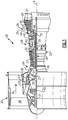
- FIG. 1 schematically illustrates a gas turbine engine 20.
- the exemplary gas turbine engine 20 is a two-spool turbofan engine that generally incorporates a fan section 22, a compressor section 24, a combustor section 26 and a turbine section 28.
- Alternative engines might include an augmenter section (not shown) among other systems for features.
- the fan section 22 drives air along a bypass flow path B, while the compressor section 24 drives air along a core flow path C for compression and communication into the combustor section 26.
- the hot combustion gases generated in the combustor section 26 are expanded through the turbine section 28.
- FIG. 1 schematically illustrates a gas turbine engine 20.
- the exemplary gas turbine engine 20 is a two-spool turbofan engine that generally incorporates a fan section 22, a compressor section 24, a combustor section 26 and a turbine section 28.
- Alternative engines might include an augmenter section (not shown) among other systems for features.
- the fan section 22 drives air along a bypass flow path B, while the compressor section 24 drives
- the gas turbine engine 20 generally includes a low speed spool 30 and a high speed spool 32 mounted for rotation about an engine centerline longitudinal axis A.
- the low speed spool 30 and the high speed spool 32 may be mounted relative to an engine static structure 33 via several bearing systems 31. It should be understood that other bearing systems 31 may alternatively or additionally be provided.
- the low speed spool 30 generally includes an inner shaft 34 that interconnects a fan 36, a low pressure compressor 38 and a low pressure turbine 39.
- the inner shaft 34 can be connected to the fan 36 through a geared architecture 45 to drive the fan 36 at a lower speed than the low speed spool 30.
- the high speed spool 32 includes an outer shaft 35 that interconnects a high pressure compressor 37 and a high pressure turbine 40.
- the inner shaft 34 and the outer shaft 35 are supported at various axial locations by bearing systems 31 positioned within the engine static structure 33.
- a combustor 42 is arranged between the high pressure compressor 37 and the high pressure turbine 40.
- a mid-turbine frame 44 may be arranged generally between the high pressure turbine 40 and the low pressure turbine 39.
- the mid-turbine frame 44 can support one or more bearing systems 31 of the turbine section 28.
- the mid-turbine frame 44 may include one or more airfoils 46 that extend within the core flow path C.
- the inner shaft 34 and the outer shaft 35 are concentric and rotate via the bearing systems 31 about the engine centerline longitudinal axis A, which is colinear with their longitudinal axes.
- the core airflow is compressed by the low pressure compressor 38 and the high pressure compressor 37, is mixed with fuel and burned in the combustor 42, and is then expanded over the high pressure turbine 40 and the low pressure turbine 39.
- the high pressure turbine 40 and the low pressure turbine 39 rotationally drive the respective high speed spool 32 and the low speed spool 30 in response to the expansion.
- the pressure ratio of the low pressure turbine 39 can be pressure measured prior to the inlet of the low pressure turbine 39 as related to the pressure at the outlet of the low pressure turbine 39 and prior to an exhaust nozzle of the gas turbine engine 20.
- the bypass ratio of the gas turbine engine 20 is greater than about ten (10:1)
- the fan diameter is significantly larger than that of the low pressure compressor 38
- the low pressure turbine 39 has a pressure ratio that is greater than about five (5:1). It should be understood, however, that the above parameters are only exemplary of one embodiment of a geared architecture engine and that the present disclosure is applicable to other gas turbine engines, including direct drive turbofans.
- TSFC Thrust Specific Fuel Consumption
- Fan Pressure Ratio is the pressure ratio across a blade of the fan section 22 without the use of a Fan Exit Guide Vane system.
- the low Fan Pressure Ratio according to one non-limiting embodiment of the example gas turbine engine 20 is less than 1.45.
- Low Corrected Fan Tip Speed is the actual fan tip speed divided by an industry standard temperature correction of [(Tram°R)/(518.7 °R)] 0.5 .
- the Low Corrected Fan Tip Speed according to one non-limiting embodiment of the example gas turbine engine 20 is less than about 1150 fps (351 m/s).
- the compressor section 24 and the turbine section 28 may include alternating rows of rotor assemblies and stator assemblies (shown schematically) that carry airfoils.
- rotor assemblies carry a plurality of rotating blades 25, while stator assemblies carry stationary stators 27 (or vanes) that extend into the core flow path C to influence the hot combustion gases.
- stator assemblies carry stationary stators 27 (or vanes) that extend into the core flow path C to influence the hot combustion gases.
- the blades 25 create or extract energy (in the form of pressure) from the core airflow that is communicated through the gas turbine engine 20 along the core flow path C.
- the stators 27 direct the core airflow to the blades 25 to either add or extract energy.
- Figure 2 illustrates a segment of a rotor/stator assembly 48 of a gas turbine engine, such as the gas turbine engine 20 of Figure 1 .
- the rotor/stator assembly 48 is part of a turbine section 28 of the gas turbine engine 20.
- the rotor/stator assembly 48 may represent part of the low pressure turbine 39 of the gas turbine engine 20.
- this disclosure is not limited to these particular sections, and the various features of this disclosure could extend to other sections of the gas turbine engine 20, including but not limited to the compressor section 24.
- the rotor/stator assembly 48 is not necessarily drawn to scale and has been enlarged to better illustrate its various features and components.
- the rotor/stator assembly 48 includes a first rotor assembly 50, a second rotor assembly 51, and a stator assembly 52 axially intermediate of the first rotor assembly 50 and the second rotor assembly 51.
- the first rotor assembly 50, the second rotor assembly 51 and the stator assembly 52 are each circumferentially disposed about the engine centerline longitudinal axis A.
- the first and second rotor assemblies 50, 51 are rotating structures that carry one or more blades 25, while the stator assembly 52 is a stationary structure having one or more stators 27.
- a support member 53 may extend between the first rotor assembly 50 and the second rotor assembly 51 such that the first and second rotor assemblies 50, 51 rotate in unison during engine operation.
- the blades 25 of the first and second rotor assemblies 50, 51 are carried by rotor disks 56 that rotate about the engine centerline longitudinal axis A to move the blades 25.
- Each rotor disk 56 includes a rim 58, a bore 60 and a web 62 that extends between the rim 58 and the bore 60.
- the blades 25 extend outwardly from the rims 58 of the rotor disk 56 toward an engine casing 55.
- a plurality of seal segments 70 may be annularly disposed in a cavity 69 that extends between the first rotor assembly 50 and the second rotor assembly 51.
- the seal segments 70 extend radially between the stator assembly 52 and the support member 53.
- the seal segments 70 form an annular seal between the core flow path C and a secondary cooling flow path F radially inward from the core flow path C (that is, between the first rotor assembly 50 and the second rotor assembly 51).
- the secondary cooling flow path F circulates a cooling fluid, such as airflow, to cool portions of the rotor assemblies 50, 51, including but not limited to the rims 58, the bores 60, and the webs 62 of the rotor disks 56 and the blades 25.
- the seal segments 70 are axially disposed between the first rotor assembly 50 and the second rotor assembly 51, and biased in place by pressure exerted by flanking rotors. In this way, the seal segments 70 rotate in unison with the rotor disks 56 to seal the cavity 69 between the rotor assemblies 50, 51 and the stator assembly 52.
- the seal segments 70 are made of a Gamma Titanium Aluminide alloy, in one embodiment. Other alloys or materials may alternatively be used to manufacture the seal segments 70.
- Figures 3A and 3B illustrate one exemplary seal segment 70 that may be incorporated into the gas turbine engine 20.
- the seal segment 70 includes a first axial wall 72, a second axial wall 74 spaced from the first axial wall 72, and a radially outer wall 76 that interconnects the first axial wall 72 and the second axial wall 74.
- the first axial wall 72 is adjacent to the first rotor assembly 50
- the second axial wall 74 is adjacent to the second rotor assembly 51
- the radially outer wall 76 interfaces with an abradable seal 78 of the stator assembly 52.
- One or more seals 80 may extend from the radially outer wall 76.
- the seals 80 circumferentially extend about the radially outer wall 76 and, in cooperation with the abradable seal 78 of the stator assembly 52, prevent core airflow of the core flow path C from bypassing the stator assembly 52.
- the first axial wall 72 and the second axial wall 74 extend radially between the radially outer wall 76 and a radially inner wall 92 (discussed below) and shield various hardware, including but not limited to the rotor disks 56 and the blades 25, from the relatively hot temperatures of the core flow path C.
- Each of the first axial wall 72 and the second axial wall 74 may include flanges 82 that engage shelves 84 of the rotor disks 56 of the rotor assemblies 50, 51. The flanges 82 abut the shelves 84 restrain the seal segment 70 from radial movement during gas turbine engine operation.
- Circumferential faces 86 (see Figure 3A ) of the seal segment 70 may include grooves 88.
- the grooves 88 are configured to receive a seal (not shown), such as, for example, a feather seal, wire seal, shiplap seal or any other type of seal.
- the seals are positioned within the grooves 88 to seal and prevent gas flow ingestion between adjacent seal segments 70.
- the grooves 88 extend across the first axial wall 72 and the second axial wall 74.
- the radially inner wall 92 of the seal segment 70 which is not a required component of the seal segment 70, is one or more curved members 92 that are radially inwardly offset from the radially outer wall 76.
- the curved members 92 extend between the first axial wall 72 and the second axial wall 74.
- the curved members 92 extend between the flanges 82 of the first and second axial walls 72, 74. Portions of the curved members 92 may extend radially inward of the flanges 82 as shown in Figure 3B .
- the curved members 92 are non-perpendicular relative to the first axial wall 72 and the second axial wall 74.
- the curved members 92 extend radially outwardly from the support member 53 that axially extends between the first rotor assembly 50 and the second rotor assembly 51. In one embodiment, the curved members 92 are generally parallel to the support member 53. In another embodiment, the curved members 92 may curve in a direction away from the radially outer wall 76 (see Figure 4 ). In yet another embodiment, the curved members 92 may curved in a direction toward the radially outer wall 76 (see Figure 5 ). This disclosure is not intended to be limited to the exact configurations shown, and it should be understood that the curved members 92 may embody other curvatures and configurations within the scope of this disclosure.
- the curved members 92 act to convey an axial force AF against the rotor disks 56.
- the curvature of the curved members 92 may exert an axial force AF which pushes the flanges 82 against the adjacent rotor disks 56 for axially retaining the segmented seal 70 between the first and second rotor assemblies 50, 51.
- the configuration of the seal segment 70 when disposed between rotors 50, 51, at least partially situates the curved member 92 in a state of compression.
- the seal segment 70 may additionally include an internal truss established by truss segments 96 that angularly extend radially and axially between the radially outer wall 76 and the flanges 82 of the first axial wall 72 and the second axial wall 74.
- the truss segments 96 support the radially outer wall 76 of the seal segment 70 and may limit radial deflection of the radially outer wall 76.
- One or more openings 98 may be defined through the first axial wall 72, the second axial wall 74 and the truss segments 96. Cooling airflow from the secondary cooling flow path F may circulate through the seal segment 70 via the openings 98. In one embodiment, the openings 98 provide a path for communicating the cooling airflow to cool the rims 58 of the rotor disks 56 and the blades 25.
Landscapes
- Engineering & Computer Science (AREA)
- Mechanical Engineering (AREA)
- General Engineering & Computer Science (AREA)
- Turbine Rotor Nozzle Sealing (AREA)
Claims (12)
- Segment de joint d'étanchéité (70) pour un moteur à turbine à gaz, comprenant :une première paroi axiale (72) ;une seconde paroi axiale (74) espacée radialement de ladite première paroi axiale (72) ;une paroi radialement extérieure (76) qui raccorde ladite première paroi axiale (72) et ladite seconde paroi axiale (74) ; etau moins un élément courbé (92) décalé radialement vers l'intérieur de ladite paroi radialement extérieure (76) et s'étendant entre lesdites première et seconde parois axiales (72, 74) ;au moins un élément de treillis (96) qui s'étend entre ladite paroi radialement extérieure (76) et ledit au moins un élément courbé (92), ledit segment de joint d'étanchéité étant caractérisé en ce que ledit au moins un élément courbé (92) transporte une force axiale contre une structure adjacente dudit segment de joint d'étanchéité.
- Segment de joint d'étanchéité selon la revendication 1, dans lequel ledit au moins un élément courbé (92) est courbé dans une direction vers ladite paroi radialement extérieure (76).
- Segment de joint d'étanchéité selon la revendication 1, dans lequel ledit au moins un élément courbé (92) est courbé dans une direction loin de ladite paroi radialement extérieure (76).
- Segment de joint d'étanchéité selon la revendication 1, 2 ou 3, dans lequel ladite paroi radialement extérieure (76) inclut une rainure qui s'étend entre ladite première paroi axiale (72) et ladite seconde paroi axiale (74), et en option dans lequel ladite rainure est configurée pour recevoir un joint d'étanchéité.
- Segment de joint d'étanchéité selon une quelconque revendication précédente, dans lequel ledit au moins un élément courbé (92) s'étend entre des brides (82) qui font saillie de ladite première paroi axiale (72) et ladite seconde paroi axiale (74).
- Segment de joint d'étanchéité selon une quelconque revendication précédente, dans lequel ledit au moins un élément courbé (92) est non perpendiculaire par rapport à ladite première paroi axiale (72) et ladite seconde paroi axiale (74).
- Segment de joint d'étanchéité selon une quelconque revendication précédente, comprenant au moins un joint d'étanchéité s'étendant depuis ladite paroi radialement extérieure (76).
- Moteur à turbine à gaz comprenant ledit segment de joint d'étanchéité (70) selon une quelconque revendication précédente, et option dans lequel ledit segment de joint d'étanchéité (70) fait partie d'une turbine à basse pression d'une section de turbine.
- Section de turbine (28), comprenant :un premier disque de rotor ;un second disque de rotor ; etun segment de joint d'étanchéité (70) selon une quelconque revendication précédente axialement entre ledit premier disque de rotor et ledit second disque de rotor, dans laquelle l'élément courbé dudit segment de joint d'étanchéité est configuré pour transporter une force axiale contre au moins un dudit premier disque de rotor et dudit second disque de rotor.
- Section de turbine selon la revendication 9, comprenant un ensemble de stator radialement vers l'extérieur dudit segment de joint d'étanchéité, et en option dans laquelle ledit ensemble de stator inclut un joint d'étanchéité abradable qui fait interface avec un joint d'étanchéité dudit segment de joint d'étanchéité.
- Moteur à turbine à gaz comprenant :un premier ensemble de rotor ;un second ensemble de rotor ;un ensemble de stator axialement entre ledit premier ensemble de rotor et ledit second ensemble de rotor ; etune pluralité de segments de joint d'étanchéité disposés dans une cavité définie entre ledit premier ensemble de rotor et ledit second ensemble de rotor, dans lequel chacun de ladite pluralité de segments de joint d'étanchéité est un segment de joint d'étanchéité selon l'une quelconque des revendications 1 à 8.
- Moteur à turbine à gaz selon la revendication 11, dans lequel chacune de ladite première paroi axiale et ladite seconde paroi axiale inclut une bride qui bute contre un rebord d'un disque de rotor dudit premier ensemble de rotor et dudit second ensemble de rotor, et en option dans lequel ledit au moins un élément courbé est sous une force compressive axiale entre lesdites brides.
Applications Claiming Priority (3)
| Application Number | Priority Date | Filing Date | Title |
|---|---|---|---|
| US201261739221P | 2012-12-19 | 2012-12-19 | |
| US201361835034P | 2013-06-14 | 2013-06-14 | |
| PCT/US2013/076347 WO2014100316A1 (fr) | 2012-12-19 | 2013-12-19 | Joint d'étanchéité segmenté de turbine à gaz |
Publications (3)
| Publication Number | Publication Date |
|---|---|
| EP2935837A1 EP2935837A1 (fr) | 2015-10-28 |
| EP2935837A4 EP2935837A4 (fr) | 2016-01-13 |
| EP2935837B1 true EP2935837B1 (fr) | 2019-02-06 |
Family
ID=50979190
Family Applications (1)
| Application Number | Title | Priority Date | Filing Date |
|---|---|---|---|
| EP13865215.1A Active EP2935837B1 (fr) | 2012-12-19 | 2013-12-19 | Joint d'étanchéité segmenté de turbine à gaz |
Country Status (3)
| Country | Link |
|---|---|
| US (1) | US10138751B2 (fr) |
| EP (1) | EP2935837B1 (fr) |
| WO (1) | WO2014100316A1 (fr) |
Families Citing this family (7)
| Publication number | Priority date | Publication date | Assignee | Title |
|---|---|---|---|---|
| US10287905B2 (en) | 2013-11-11 | 2019-05-14 | United Technologies Corporation | Segmented seal for gas turbine engine |
| US10077666B2 (en) * | 2014-09-23 | 2018-09-18 | United Technologies Corporation | Method and assembly for reducing secondary heat in a gas turbine engine |
| US10337345B2 (en) * | 2015-02-20 | 2019-07-02 | General Electric Company | Bucket mounted multi-stage turbine interstage seal and method of assembly |
| US10641129B2 (en) * | 2017-11-08 | 2020-05-05 | United Technologies Corporation | Support rail truss for gas turbine engines |
| US10644630B2 (en) | 2017-11-28 | 2020-05-05 | General Electric Company | Turbomachine with an electric machine assembly and method for operation |
| US11428171B2 (en) | 2019-12-06 | 2022-08-30 | General Electric Company | Electric machine assistance for multi-spool turbomachine operation and control |
| US11506060B1 (en) * | 2021-07-15 | 2022-11-22 | Honeywell International Inc. | Radial turbine rotor for gas turbine engine |
Family Cites Families (18)
| Publication number | Priority date | Publication date | Assignee | Title |
|---|---|---|---|---|
| US3733146A (en) * | 1971-04-07 | 1973-05-15 | United Aircraft Corp | Gas seal rotatable support structure |
| US4094673A (en) * | 1974-02-28 | 1978-06-13 | Brunswick Corporation | Abradable seal material and composition thereof |
| US4470757A (en) * | 1982-02-25 | 1984-09-11 | United Technologies Corporation | Sideplate retention for a turbine rotor |
| US4645424A (en) * | 1984-07-23 | 1987-02-24 | United Technologies Corporation | Rotating seal for gas turbine engine |
| US4884950A (en) * | 1988-09-06 | 1989-12-05 | United Technologies Corporation | Segmented interstage seal assembly |
| GB2307520B (en) * | 1995-11-14 | 1999-07-07 | Rolls Royce Plc | A gas turbine engine |
| US5785775A (en) * | 1997-01-22 | 1998-07-28 | General Electric Company | Welding of gamma titanium aluminide alloys |
| FR2825748B1 (fr) | 2001-06-07 | 2003-11-07 | Snecma Moteurs | Agencement de rotor de turbomachine a deux disques aubages separes par une entretoise |
| DE10318852A1 (de) | 2003-04-25 | 2004-11-11 | Rolls-Royce Deutschland Ltd & Co Kg | Hauptgaskanal-Innendichtung einer Hochdruckturbine |
| GB2438858B (en) | 2006-06-07 | 2008-08-06 | Rolls Royce Plc | A sealing arrangement in a gas turbine engine |
| GB0703827D0 (en) | 2007-02-28 | 2007-04-11 | Rolls Royce Plc | Rotor seal segment |
| US8240980B1 (en) | 2007-10-19 | 2012-08-14 | Florida Turbine Technologies, Inc. | Turbine inter-stage gap cooling and sealing arrangement |
| US8240986B1 (en) | 2007-12-21 | 2012-08-14 | Florida Turbine Technologies, Inc. | Turbine inter-stage seal control |
| US8388309B2 (en) | 2008-09-25 | 2013-03-05 | Siemens Energy, Inc. | Gas turbine sealing apparatus |
| US8221062B2 (en) | 2009-01-14 | 2012-07-17 | General Electric Company | Device and system for reducing secondary air flow in a gas turbine |
| US8616850B2 (en) * | 2010-06-11 | 2013-12-31 | United Technologies Corporation | Gas turbine engine blade mounting arrangement |
| US20120321437A1 (en) * | 2011-06-17 | 2012-12-20 | General Electric Company | Turbine seal system |
| US9540940B2 (en) * | 2012-03-12 | 2017-01-10 | General Electric Company | Turbine interstage seal system |
-
2013
- 2013-12-19 EP EP13865215.1A patent/EP2935837B1/fr active Active
- 2013-12-19 US US14/733,984 patent/US10138751B2/en active Active
- 2013-12-19 WO PCT/US2013/076347 patent/WO2014100316A1/fr active Application Filing
Non-Patent Citations (1)
| Title |
|---|
| None * |
Also Published As
| Publication number | Publication date |
|---|---|
| EP2935837A1 (fr) | 2015-10-28 |
| US20150377052A1 (en) | 2015-12-31 |
| EP2935837A4 (fr) | 2016-01-13 |
| WO2014100316A1 (fr) | 2014-06-26 |
| US10138751B2 (en) | 2018-11-27 |
Similar Documents
| Publication | Publication Date | Title |
|---|---|---|
| EP2935837B1 (fr) | Joint d'étanchéité segmenté de turbine à gaz | |
| US10436070B2 (en) | Blade outer air seal having angled retention hook | |
| US9115596B2 (en) | Blade outer air seal having anti-rotation feature | |
| EP2964934B1 (fr) | Composant de moteur à turbine à gaz ayant une fente de joint à couvre-joint à largeur variable | |
| EP2952689B1 (fr) | Espaceur de joint de bordure segmentée pour un moteur à turbine à gaz | |
| EP2938839B1 (fr) | Joint d'étanchéité à l'air extérieur de pale ayant une structure à feuillure | |
| US10436054B2 (en) | Blade outer air seal for a gas turbine engine | |
| US10184345B2 (en) | Cover plate assembly for a gas turbine engine | |
| US10655481B2 (en) | Cover plate for rotor assembly of a gas turbine engine | |
| US20130177387A1 (en) | Intersegment spring "t" seal | |
| US20180328207A1 (en) | Gas turbine engine component having tip vortex creation feature | |
| EP2885520B1 (fr) | Composant pour un moteur à turbine à gaz et procédé de refroidissement associé | |
| EP3159492B1 (fr) | Passages de refroidissement pour composant de moteur à turbine à gaz |
Legal Events
| Date | Code | Title | Description |
|---|---|---|---|
| PUAI | Public reference made under article 153(3) epc to a published international application that has entered the european phase |
Free format text: ORIGINAL CODE: 0009012 |
|
| 17P | Request for examination filed |
Effective date: 20150720 |
|
| AK | Designated contracting states |
Kind code of ref document: A1 Designated state(s): AL AT BE BG CH CY CZ DE DK EE ES FI FR GB GR HR HU IE IS IT LI LT LU LV MC MK MT NL NO PL PT RO RS SE SI SK SM TR |
|
| AX | Request for extension of the european patent |
Extension state: BA ME |
|
| A4 | Supplementary search report drawn up and despatched |
Effective date: 20151215 |
|
| RIC1 | Information provided on ipc code assigned before grant |
Ipc: F01D 11/00 20060101AFI20151209BHEP |
|
| DAX | Request for extension of the european patent (deleted) | ||
| RAP1 | Party data changed (applicant data changed or rights of an application transferred) |
Owner name: UNITED TECHNOLOGIES CORPORATION |
|
| GRAP | Despatch of communication of intention to grant a patent |
Free format text: ORIGINAL CODE: EPIDOSNIGR1 |
|
| STAA | Information on the status of an ep patent application or granted ep patent |
Free format text: STATUS: GRANT OF PATENT IS INTENDED |
|
| INTG | Intention to grant announced |
Effective date: 20180727 |
|
| GRAS | Grant fee paid |
Free format text: ORIGINAL CODE: EPIDOSNIGR3 |
|
| GRAA | (expected) grant |
Free format text: ORIGINAL CODE: 0009210 |
|
| STAA | Information on the status of an ep patent application or granted ep patent |
Free format text: STATUS: THE PATENT HAS BEEN GRANTED |
|
| AK | Designated contracting states |
Kind code of ref document: B1 Designated state(s): AL AT BE BG CH CY CZ DE DK EE ES FI FR GB GR HR HU IE IS IT LI LT LU LV MC MK MT NL NO PL PT RO RS SE SI SK SM TR |
|
| REG | Reference to a national code |
Ref country code: GB Ref legal event code: FG4D |
|
| REG | Reference to a national code |
Ref country code: CH Ref legal event code: EP Ref country code: AT Ref legal event code: REF Ref document number: 1095051 Country of ref document: AT Kind code of ref document: T Effective date: 20190215 |
|
| REG | Reference to a national code |
Ref country code: DE Ref legal event code: R096 Ref document number: 602013050630 Country of ref document: DE |
|
| REG | Reference to a national code |
Ref country code: IE Ref legal event code: FG4D |
|
| REG | Reference to a national code |
Ref country code: NL Ref legal event code: MP Effective date: 20190206 |
|
| REG | Reference to a national code |
Ref country code: LT Ref legal event code: MG4D |
|
| PG25 | Lapsed in a contracting state [announced via postgrant information from national office to epo] |
Ref country code: NL Free format text: LAPSE BECAUSE OF FAILURE TO SUBMIT A TRANSLATION OF THE DESCRIPTION OR TO PAY THE FEE WITHIN THE PRESCRIBED TIME-LIMIT Effective date: 20190206 Ref country code: LT Free format text: LAPSE BECAUSE OF FAILURE TO SUBMIT A TRANSLATION OF THE DESCRIPTION OR TO PAY THE FEE WITHIN THE PRESCRIBED TIME-LIMIT Effective date: 20190206 Ref country code: NO Free format text: LAPSE BECAUSE OF FAILURE TO SUBMIT A TRANSLATION OF THE DESCRIPTION OR TO PAY THE FEE WITHIN THE PRESCRIBED TIME-LIMIT Effective date: 20190506 Ref country code: FI Free format text: LAPSE BECAUSE OF FAILURE TO SUBMIT A TRANSLATION OF THE DESCRIPTION OR TO PAY THE FEE WITHIN THE PRESCRIBED TIME-LIMIT Effective date: 20190206 Ref country code: PT Free format text: LAPSE BECAUSE OF FAILURE TO SUBMIT A TRANSLATION OF THE DESCRIPTION OR TO PAY THE FEE WITHIN THE PRESCRIBED TIME-LIMIT Effective date: 20190606 Ref country code: SE Free format text: LAPSE BECAUSE OF FAILURE TO SUBMIT A TRANSLATION OF THE DESCRIPTION OR TO PAY THE FEE WITHIN THE PRESCRIBED TIME-LIMIT Effective date: 20190206 |
|
| REG | Reference to a national code |
Ref country code: AT Ref legal event code: MK05 Ref document number: 1095051 Country of ref document: AT Kind code of ref document: T Effective date: 20190206 |
|
| PG25 | Lapsed in a contracting state [announced via postgrant information from national office to epo] |
Ref country code: HR Free format text: LAPSE BECAUSE OF FAILURE TO SUBMIT A TRANSLATION OF THE DESCRIPTION OR TO PAY THE FEE WITHIN THE PRESCRIBED TIME-LIMIT Effective date: 20190206 Ref country code: RS Free format text: LAPSE BECAUSE OF FAILURE TO SUBMIT A TRANSLATION OF THE DESCRIPTION OR TO PAY THE FEE WITHIN THE PRESCRIBED TIME-LIMIT Effective date: 20190206 Ref country code: LV Free format text: LAPSE BECAUSE OF FAILURE TO SUBMIT A TRANSLATION OF THE DESCRIPTION OR TO PAY THE FEE WITHIN THE PRESCRIBED TIME-LIMIT Effective date: 20190206 Ref country code: BG Free format text: LAPSE BECAUSE OF FAILURE TO SUBMIT A TRANSLATION OF THE DESCRIPTION OR TO PAY THE FEE WITHIN THE PRESCRIBED TIME-LIMIT Effective date: 20190506 Ref country code: GR Free format text: LAPSE BECAUSE OF FAILURE TO SUBMIT A TRANSLATION OF THE DESCRIPTION OR TO PAY THE FEE WITHIN THE PRESCRIBED TIME-LIMIT Effective date: 20190507 Ref country code: IS Free format text: LAPSE BECAUSE OF FAILURE TO SUBMIT A TRANSLATION OF THE DESCRIPTION OR TO PAY THE FEE WITHIN THE PRESCRIBED TIME-LIMIT Effective date: 20190606 |
|
| PG25 | Lapsed in a contracting state [announced via postgrant information from national office to epo] |
Ref country code: AL Free format text: LAPSE BECAUSE OF FAILURE TO SUBMIT A TRANSLATION OF THE DESCRIPTION OR TO PAY THE FEE WITHIN THE PRESCRIBED TIME-LIMIT Effective date: 20190206 Ref country code: ES Free format text: LAPSE BECAUSE OF FAILURE TO SUBMIT A TRANSLATION OF THE DESCRIPTION OR TO PAY THE FEE WITHIN THE PRESCRIBED TIME-LIMIT Effective date: 20190206 Ref country code: DK Free format text: LAPSE BECAUSE OF FAILURE TO SUBMIT A TRANSLATION OF THE DESCRIPTION OR TO PAY THE FEE WITHIN THE PRESCRIBED TIME-LIMIT Effective date: 20190206 Ref country code: EE Free format text: LAPSE BECAUSE OF FAILURE TO SUBMIT A TRANSLATION OF THE DESCRIPTION OR TO PAY THE FEE WITHIN THE PRESCRIBED TIME-LIMIT Effective date: 20190206 Ref country code: IT Free format text: LAPSE BECAUSE OF FAILURE TO SUBMIT A TRANSLATION OF THE DESCRIPTION OR TO PAY THE FEE WITHIN THE PRESCRIBED TIME-LIMIT Effective date: 20190206 Ref country code: SK Free format text: LAPSE BECAUSE OF FAILURE TO SUBMIT A TRANSLATION OF THE DESCRIPTION OR TO PAY THE FEE WITHIN THE PRESCRIBED TIME-LIMIT Effective date: 20190206 Ref country code: RO Free format text: LAPSE BECAUSE OF FAILURE TO SUBMIT A TRANSLATION OF THE DESCRIPTION OR TO PAY THE FEE WITHIN THE PRESCRIBED TIME-LIMIT Effective date: 20190206 Ref country code: CZ Free format text: LAPSE BECAUSE OF FAILURE TO SUBMIT A TRANSLATION OF THE DESCRIPTION OR TO PAY THE FEE WITHIN THE PRESCRIBED TIME-LIMIT Effective date: 20190206 |
|
| REG | Reference to a national code |
Ref country code: DE Ref legal event code: R097 Ref document number: 602013050630 Country of ref document: DE |
|
| PG25 | Lapsed in a contracting state [announced via postgrant information from national office to epo] |
Ref country code: SM Free format text: LAPSE BECAUSE OF FAILURE TO SUBMIT A TRANSLATION OF THE DESCRIPTION OR TO PAY THE FEE WITHIN THE PRESCRIBED TIME-LIMIT Effective date: 20190206 Ref country code: PL Free format text: LAPSE BECAUSE OF FAILURE TO SUBMIT A TRANSLATION OF THE DESCRIPTION OR TO PAY THE FEE WITHIN THE PRESCRIBED TIME-LIMIT Effective date: 20190206 |
|
| PLBE | No opposition filed within time limit |
Free format text: ORIGINAL CODE: 0009261 |
|
| STAA | Information on the status of an ep patent application or granted ep patent |
Free format text: STATUS: NO OPPOSITION FILED WITHIN TIME LIMIT |
|
| PG25 | Lapsed in a contracting state [announced via postgrant information from national office to epo] |
Ref country code: AT Free format text: LAPSE BECAUSE OF FAILURE TO SUBMIT A TRANSLATION OF THE DESCRIPTION OR TO PAY THE FEE WITHIN THE PRESCRIBED TIME-LIMIT Effective date: 20190206 |
|
| 26N | No opposition filed |
Effective date: 20191107 |
|
| PG25 | Lapsed in a contracting state [announced via postgrant information from national office to epo] |
Ref country code: SI Free format text: LAPSE BECAUSE OF FAILURE TO SUBMIT A TRANSLATION OF THE DESCRIPTION OR TO PAY THE FEE WITHIN THE PRESCRIBED TIME-LIMIT Effective date: 20190206 |
|
| PG25 | Lapsed in a contracting state [announced via postgrant information from national office to epo] |
Ref country code: TR Free format text: LAPSE BECAUSE OF FAILURE TO SUBMIT A TRANSLATION OF THE DESCRIPTION OR TO PAY THE FEE WITHIN THE PRESCRIBED TIME-LIMIT Effective date: 20190206 |
|
| REG | Reference to a national code |
Ref country code: CH Ref legal event code: PL |
|
| REG | Reference to a national code |
Ref country code: BE Ref legal event code: MM Effective date: 20191231 |
|
| PG25 | Lapsed in a contracting state [announced via postgrant information from national office to epo] |
Ref country code: MC Free format text: LAPSE BECAUSE OF FAILURE TO SUBMIT A TRANSLATION OF THE DESCRIPTION OR TO PAY THE FEE WITHIN THE PRESCRIBED TIME-LIMIT Effective date: 20190206 |
|
| PG25 | Lapsed in a contracting state [announced via postgrant information from national office to epo] |
Ref country code: IE Free format text: LAPSE BECAUSE OF NON-PAYMENT OF DUE FEES Effective date: 20191219 Ref country code: LU Free format text: LAPSE BECAUSE OF NON-PAYMENT OF DUE FEES Effective date: 20191219 |
|
| PG25 | Lapsed in a contracting state [announced via postgrant information from national office to epo] |
Ref country code: LI Free format text: LAPSE BECAUSE OF NON-PAYMENT OF DUE FEES Effective date: 20191231 Ref country code: BE Free format text: LAPSE BECAUSE OF NON-PAYMENT OF DUE FEES Effective date: 20191231 Ref country code: CH Free format text: LAPSE BECAUSE OF NON-PAYMENT OF DUE FEES Effective date: 20191231 |
|
| PG25 | Lapsed in a contracting state [announced via postgrant information from national office to epo] |
Ref country code: CY Free format text: LAPSE BECAUSE OF FAILURE TO SUBMIT A TRANSLATION OF THE DESCRIPTION OR TO PAY THE FEE WITHIN THE PRESCRIBED TIME-LIMIT Effective date: 20190206 |
|
| PG25 | Lapsed in a contracting state [announced via postgrant information from national office to epo] |
Ref country code: MT Free format text: LAPSE BECAUSE OF FAILURE TO SUBMIT A TRANSLATION OF THE DESCRIPTION OR TO PAY THE FEE WITHIN THE PRESCRIBED TIME-LIMIT Effective date: 20190206 Ref country code: HU Free format text: LAPSE BECAUSE OF FAILURE TO SUBMIT A TRANSLATION OF THE DESCRIPTION OR TO PAY THE FEE WITHIN THE PRESCRIBED TIME-LIMIT; INVALID AB INITIO Effective date: 20131219 |
|
| PG25 | Lapsed in a contracting state [announced via postgrant information from national office to epo] |
Ref country code: MK Free format text: LAPSE BECAUSE OF FAILURE TO SUBMIT A TRANSLATION OF THE DESCRIPTION OR TO PAY THE FEE WITHIN THE PRESCRIBED TIME-LIMIT Effective date: 20190206 |
|
| REG | Reference to a national code |
Ref country code: DE Ref legal event code: R081 Ref document number: 602013050630 Country of ref document: DE Owner name: RAYTHEON TECHNOLOGIES CORPORATION (N.D.GES.D.S, US Free format text: FORMER OWNER: UNITED TECHNOLOGIES CORPORATION, FARMINGTON, CONN., US |
|
| P01 | Opt-out of the competence of the unified patent court (upc) registered |
Effective date: 20230520 |
|
| PGFP | Annual fee paid to national office [announced via postgrant information from national office to epo] |
Ref country code: GB Payment date: 20231124 Year of fee payment: 11 |
|
| PGFP | Annual fee paid to national office [announced via postgrant information from national office to epo] |
Ref country code: FR Payment date: 20231122 Year of fee payment: 11 Ref country code: DE Payment date: 20231121 Year of fee payment: 11 |