EP2935800B1 - Variable outer air seal fluid control - Google Patents
Variable outer air seal fluid control Download PDFInfo
- Publication number
- EP2935800B1 EP2935800B1 EP13866444.6A EP13866444A EP2935800B1 EP 2935800 B1 EP2935800 B1 EP 2935800B1 EP 13866444 A EP13866444 A EP 13866444A EP 2935800 B1 EP2935800 B1 EP 2935800B1
- Authority
- EP
- European Patent Office
- Prior art keywords
- outer air
- air seal
- blade outer
- variable blade
- variable
- Prior art date
- Legal status (The legal status is an assumption and is not a legal conclusion. Google has not performed a legal analysis and makes no representation as to the accuracy of the status listed.)
- Active
Links
- 239000012530 fluid Substances 0.000 title claims description 14
- 238000001816 cooling Methods 0.000 claims description 13
- 238000000034 method Methods 0.000 claims description 10
- 239000012809 cooling fluid Substances 0.000 claims description 2
- 230000006835 compression Effects 0.000 description 8
- 238000007906 compression Methods 0.000 description 8
- 238000002485 combustion reaction Methods 0.000 description 5
- 239000000446 fuel Substances 0.000 description 4
- 238000003491 array Methods 0.000 description 1
- 230000000903 blocking effect Effects 0.000 description 1
- 230000001276 controlling effect Effects 0.000 description 1
- 238000012937 correction Methods 0.000 description 1
- 230000007423 decrease Effects 0.000 description 1
- 238000013461 design Methods 0.000 description 1
- 238000005259 measurement Methods 0.000 description 1
- 238000012986 modification Methods 0.000 description 1
- 230000004048 modification Effects 0.000 description 1
- 230000001105 regulatory effect Effects 0.000 description 1
- 239000000523 sample Substances 0.000 description 1
- 230000003685 thermal hair damage Effects 0.000 description 1
Images


Classifications
-
- F—MECHANICAL ENGINEERING; LIGHTING; HEATING; WEAPONS; BLASTING
- F02—COMBUSTION ENGINES; HOT-GAS OR COMBUSTION-PRODUCT ENGINE PLANTS
- F02C—GAS-TURBINE PLANTS; AIR INTAKES FOR JET-PROPULSION PLANTS; CONTROLLING FUEL SUPPLY IN AIR-BREATHING JET-PROPULSION PLANTS
- F02C7/00—Features, components parts, details or accessories, not provided for in, or of interest apart form groups F02C1/00 - F02C6/00; Air intakes for jet-propulsion plants
- F02C7/28—Arrangement of seals
-
- F—MECHANICAL ENGINEERING; LIGHTING; HEATING; WEAPONS; BLASTING
- F01—MACHINES OR ENGINES IN GENERAL; ENGINE PLANTS IN GENERAL; STEAM ENGINES
- F01D—NON-POSITIVE DISPLACEMENT MACHINES OR ENGINES, e.g. STEAM TURBINES
- F01D11/00—Preventing or minimising internal leakage of working-fluid, e.g. between stages
- F01D11/08—Preventing or minimising internal leakage of working-fluid, e.g. between stages for sealing space between rotor blade tips and stator
- F01D11/10—Preventing or minimising internal leakage of working-fluid, e.g. between stages for sealing space between rotor blade tips and stator using sealing fluid, e.g. steam
-
- F—MECHANICAL ENGINEERING; LIGHTING; HEATING; WEAPONS; BLASTING
- F01—MACHINES OR ENGINES IN GENERAL; ENGINE PLANTS IN GENERAL; STEAM ENGINES
- F01D—NON-POSITIVE DISPLACEMENT MACHINES OR ENGINES, e.g. STEAM TURBINES
- F01D11/00—Preventing or minimising internal leakage of working-fluid, e.g. between stages
- F01D11/08—Preventing or minimising internal leakage of working-fluid, e.g. between stages for sealing space between rotor blade tips and stator
- F01D11/14—Adjusting or regulating tip-clearance, i.e. distance between rotor-blade tips and stator casing
- F01D11/20—Actively adjusting tip-clearance
- F01D11/22—Actively adjusting tip-clearance by mechanically actuating the stator or rotor components, e.g. moving shroud sections relative to the rotor
-
- F—MECHANICAL ENGINEERING; LIGHTING; HEATING; WEAPONS; BLASTING
- F01—MACHINES OR ENGINES IN GENERAL; ENGINE PLANTS IN GENERAL; STEAM ENGINES
- F01D—NON-POSITIVE DISPLACEMENT MACHINES OR ENGINES, e.g. STEAM TURBINES
- F01D11/00—Preventing or minimising internal leakage of working-fluid, e.g. between stages
- F01D11/08—Preventing or minimising internal leakage of working-fluid, e.g. between stages for sealing space between rotor blade tips and stator
- F01D11/14—Adjusting or regulating tip-clearance, i.e. distance between rotor-blade tips and stator casing
- F01D11/20—Actively adjusting tip-clearance
- F01D11/24—Actively adjusting tip-clearance by selectively cooling-heating stator or rotor components
Definitions
- This disclosure relates to a blade outer air seal (BOAS) assembly for a turbomachine and, more particularly, to a BOAS assembly having segments that are moved relative to each other to selectively communicate fluid.
- BOAS blade outer air seal
- Turbomachines such as gas turbine engines, typically include a fan section, a compression section, a combustion section, and a turbine section. Turbomachines may employ a geared architecture connecting portions of the compression section to the fan section.
- BOAS circumscribe arrays of blades in the compression section, turbine section, or both.
- Turbomachines have developed passive and active systems for controlling clearances of the gap between the outer air seal and the tip of the turbine blade. Significant and varied thermal energy levels may be concentrated in these areas. Cooling these areas is often difficult. Specific and dedicated components are used to provide flow and cooling, which adds weight and cost.
- DE 19855130 discloses a coolable casing formed with a plurality of arcuate casing segments having a plurality of passage orifice.
- turbomachine system as set forth in claim 1.
- the at least one channel may extend from a radially outward facing surface to a radially inward facing surface.
- the at least one channel may extend to a circumferentially facing surface.
- the first and second variable outer air seal may be circumferentially adjacent.
- the first variable outer air seal may include an inclined surface, and the second variable outer air seal may move across the inclined surface to selectively communicate fluid.
- the first and second variable outer air seals may have a shiplapped configuration.
- the first and second variable outer air seals may be moveable relative to each other between a first position and a second position to selectively control fluid flow through at least one channel.
- the first and second variable outer air seals may circumferentially overlap each other when in the first position more than when in the second position.
- the invention also extends to a method of turbomachine cooling air control according to claim 8.
- the channel may be provided by the second variable outer air seal.
- moving the first variable outer air seal relative to the second variable outer air seal controls the flow of a cooling fluid.
- the moving may comprise moving the first and second variable outer air seals circumferentially relative to each other.
- FIG. 1 schematically illustrates an example turbomachine, which is a gas turbine engine 20 in this example.
- the gas turbine engine 20 is a two-spool turbofan gas turbine engine that generally includes a fan section 22, a compression section 24, a combustion section 26, and a turbine section 28.
- turbofan gas turbine engine Although depicted as a two-spool turbofan gas turbine engine in the disclosed non-limiting embodiment, it should be understood that the concepts described herein are not limited to use with turbofans. That is, the teachings may be applied to other types of turbomachines and turbine engines including three-spool architectures. Further, the concepts described herein could be used in environments other than a turbomachine environment and in applications other than aerospace applications.
- flow moves from the fan section 22 to a bypass flowpath.
- Flow from the bypass flowpath generates thrust.
- the compression section 24 drives air along a core flowpath. Compressed air from the compression section 24 communicates through the combustion section 26. The products of combustion expand through the turbine section 28.
- the example engine 20 generally includes a low-speed spool 30 and a high-speed spool 32 mounted for rotation about an engine central axis A.
- the low-speed spool 30 and the high-speed spool 32 are rotatably supported by several bearing systems 38. It should be understood that various bearing systems 38 at various locations may alternatively, or additionally, be provided.
- the low-speed spool 30 generally includes a shaft 40 that interconnects a fan 42, a low-pressure compressor 44, and a low-pressure turbine 46.
- the shaft 40 is connected to the fan 42 through a geared architecture 48 to drive the fan 42 at a lower speed than the low-speed spool 30.
- the high-speed spool 32 includes a shaft 50 that interconnects a high-pressure compressor 52 and high-pressure turbine 54.
- the shaft 40 and the shaft 50 are concentric and rotate via bearing systems 38 about the engine central longitudinal axis A, which is collinear with the longitudinal axes of the shaft 40 and the shaft 50.
- the combustion section 26 includes a circumferentially distributed array of fuel nozzles within an annular combustor 56 that is generally arranged axially between the high-pressure compressor 52 and the high-pressure turbine 54.
- the engine 20 is a high-bypass geared aircraft engine. In a further example, the engine 20 bypass ratio is greater than about six (6 to 1).
- the geared architecture 48 of the example engine 20 includes an epicyclic gear train, such as a planetary gear system or other gear system.
- the example epicyclic gear train has a gear reduction ratio of greater than about 2.3 (2.3 to 1).
- the low-pressure turbine 46 pressure ratio is pressure measured prior to inlet of low-pressure turbine 46 as related to the pressure at the outlet of the low-pressure turbine 46 prior to an exhaust nozzle of the engine 20.
- the bypass ratio of the engine 20 is greater than about ten (10 to 1)
- the fan diameter is significantly larger than that of the low-pressure compressor 44
- the low-pressure turbine 46 has a pressure ratio that is greater than about 5 (5 to 1).
- the geared architecture 48 of this embodiment is an epicyclic gear train with a gear reduction ratio of greater than about 2.5 (2.5 to 1). It should be understood, however, that the above parameters are only exemplary of one embodiment of a geared architecture engine and that the present disclosure is applicable to other gas turbine engines including direct drive turbofans.
- TSFC Thrust Specific Fuel Consumption
- Fan Pressure Ratio is the pressure ratio across a blade of the fan section 22 without the use of a Fan Exit Guide Vane system.
- the low Fan Pressure Ratio according to one non-limiting embodiment of the example engine 20 is less than 1.45 (1.45 to 1).
- Low Corrected Fan Tip Speed is the actual fan tip speed in ft/sec divided by an industry standard temperature correction of [(Tram °R) / (518.7 °R)] ⁇ 0.5.
- the Temperature represents the ambient temperature in degrees Rankine.
- the Low Corrected Fan Tip Speed according to one non-limiting embodiment of the example engine 20 is less than about 1150 fps (351 m/s).
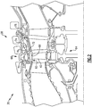
- the turbine section 28 of the engine 20 includes a blade outer air seal (“BOAS") assembly 60 disposed between a plurality of circumferentially distributed rotor blades 62 of a rotor stage 64, and an annular outer engine case 66.
- the BOAS 60 is adapted to limit air leakage between blade tips 68 and the engine case 66.
- the example BOAS 60 is supported by rails 70 and 72 attached to the engine case 66.
- BOAS 60 is also connected to an actuator 74 through a rod 76.
- the actuator 74 may connect to a main digital control.
- the actuator 74 may be wired to a control system via a cable 78. In other examples, the actuator 74 attaches the main digital electronic control of the engine 20 in another ways.
- the BOAS 60 includes multiple variable outer air seal segments 80 distributed annularly about the axis A.
- each segment has radially inwardly facing surfaces 82 and radially outwardly facing surfaces 84.
- the segments 82 each include an inclined surface 86 attached to a base portion 88.
- the inclined surface 86 is one of the radially outwardly facing surfaces 84 in this example.
- An extension 90 extends radially outward from the base portion 88.
- the extension 90 may be a stanchion, tab, lug, or some other structure.
- the extension 90 has an aperture 92 for receiving a connector pin 94.
- Each segment 80 is connected to a circumferentially adjacent segment through a link 96 attached with the pin 94. Some of the segments, 80a and 80b are attached to a single circumferentially adjacent segment 80. Segment 80b is attached to the actuating rod 76. Actuating rod 76 is directly coupled to the actuator 74. Actuator 74 is attached to a control system 100 via the cable 78.
- the control system 100 includes a sensor 102, for example a thermocouple, which may be positioned to sense a gas path temperature at a particular location along a core flow path of the engine.
- the sensor 102 extends through a turbine case to measure a temperature approximate location T4 at the entrance to the high-pressure turbine section, where airfoils and other components are particularly susceptible to thermal damage due to peaking gas temperatures.
- temperature sensor 102 may be positioned approximate another stage of the high-pressure turbine 54, or within the low-pressure turbine 46, or a compression section 24.
- a number of temperature probes are positioned in different locations within the engine 20 to measure multiple gas path temperatures along flowpaths of the engine 20.
- the control system 100 includes a flight controller 104 having a flight condition module, a thrust control, and other related engine functions.
- the flight controller 104 may comprise additional flight, engine, and navigational systems utilizing other control, sensor, and processor components located throughout the engine 20, and in other regions of the engine.
- Flight controller 104 includes a combination of software and hardware components configured to determine and report flight conditions relevant to the operation of engine 20.
- flight controller 104 includes a number of individual flight modules, which determine a range of different flight conditions based on a combination of pressure, temperature and spool speed measurements and additional data such as attitude and control surface positions.
- Flight controller 104 may include a control law (CLW) configured to direct actuator 74 to adjust the modulated BOAS 60.
- CLW control law
- the CLW directs actuator 74 based on the sensed inputs from sensor 102, the flight conditions determined by flight module, and other parameters, such as core flow gas path temperatures TC.
- the flight controller 104 may direct the actuator 74 to adjust rod 76 in order to regulate the gap between the blade tips and radially inward facing surfaces 82 of the segments 80.
- the linkage design connected to modulated BOAS 60 is designed such that if pushed in one direction, linkages are pulled in tension, thus increasing the diameter of the modulated BOAS 60, while movement in the other direction creates compression within the linkages and decreases the overall diameter of modulated BOAS 60.
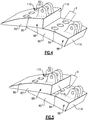
- adjacent ones of the segments 80 are moveable to shiplapped positions. When shiplapped, portions of circumferentially adjacent segments 80 overlap each other.
- the flight controller 104 may direct the actuator 74 to adjust rod 76 to move circumferentially adjacent segments 80' and 80" ( FIG. 4 and 5 ) between the less shiplapped position of FIG. 4 and the more shiplapped position of FIG. 5 .
- the actuator 74 may be configured to move the circumferentially adjacent segments 80' and 80" to positions where no portion of circumferentially adjacent segments 80' and 80" overlap.
- the example segments 80' and 80" include channels 110 extending from the inclined surface 86 to a radially inward facing surface 82.
- the channels 110 deliver a fluid, such as cooling air from a supply 112 to an interface between the radially inward facing surface 82 and the blade tip 68.
- the supply 112 is radially outside the segments 80' and 80" in this example.
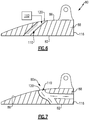
- the flight controller 104 may direct the actuator 74 to adjust rod 76 in order to regulate flow of fluid through the channels 110.
- the fluid cools the interface.
- the flow is regulated by selectively blocking flow entering an inlet 120 of the channels 110.
- the segment 80' is used to selectively block the flow through channels 110 in the segment 80".
- the segment 80' blocks flow through the channels 110 in the segment 80" by covering some or all of the inlets 120 in the segment 80".
- increasing the circumferential overlap between the segments 80' and 80" increases the amount of blocked flow and reduces the amount of flow moving through channels 110.
- the amount of blocked flow may thus be controlled by varying the amount of overlap between the segment 80 and the inlets 120.
- the example channels 110 are shown as being entirely within a single one of the segments 80' or 80". In other examples, the channels 110 may be defined partially by one of the segments 80' or 80", such as if the channels 110 were notches in a side of one of the segments 80' and 80".
- the example channels 110 deliver fluid to the radially inward facing surfaces 82 interacting with the blade tip 68.
- the channels 110 may instead, or in addition to, deliver fluid to other areas, such as to a circumferentially facing surface 116 of the segments 80 ( FIG. 7 ).
- the size, angles, and positions of the channels 110 are adjustable according to specific cycle requirements, method or control, etc.
Description
- This disclosure relates to a blade outer air seal (BOAS) assembly for a turbomachine and, more particularly, to a BOAS assembly having segments that are moved relative to each other to selectively communicate fluid.
- Turbomachines, such as gas turbine engines, typically include a fan section, a compression section, a combustion section, and a turbine section. Turbomachines may employ a geared architecture connecting portions of the compression section to the fan section.
- BOAS circumscribe arrays of blades in the compression section, turbine section, or both. Turbomachines have developed passive and active systems for controlling clearances of the gap between the outer air seal and the tip of the turbine blade. Significant and varied thermal energy levels may be concentrated in these areas. Cooling these areas is often difficult. Specific and dedicated components are used to provide flow and cooling, which adds weight and cost.
-
DE 19855130 discloses a coolable casing formed with a plurality of arcuate casing segments having a plurality of passage orifice. - According to the invention, there is provided a turbomachine system as set forth in claim 1.
- In a non-limiting embodiment of the foregoing turbomachine system, the at least one channel may extend from a radially outward facing surface to a radially inward facing surface.
- In a further non-limiting embodiment of either of the foregoing turbomachine systems, the at least one channel may extend to a circumferentially facing surface.
- In a further non-limiting embodiment of any of the foregoing turbomachine systems, the first and second variable outer air seal may be circumferentially adjacent.
- In a further non-limiting embodiment of any of the foregoing turbomachine systems, the first variable outer air seal may include an inclined surface, and the second variable outer air seal may move across the inclined surface to selectively communicate fluid.
- In a further non-limiting embodiment of any of the foregoing turbomachine systems, the first and second variable outer air seals may have a shiplapped configuration.
- In a further non-limiting embodiment of any of the foregoing turbomachine systems, the first and second variable outer air seals may be moveable relative to each other between a first position and a second position to selectively control fluid flow through at least one channel. The first and second variable outer air seals may circumferentially overlap each other when in the first position more than when in the second position.
- The invention also extends to a method of turbomachine cooling air control according to claim 8.
- In a further non-limiting embodiment of either of the foregoing methods of turbomachine fluid control, the channel may be provided by the second variable outer air seal.
- In a further non-limiting embodiment of any of the foregoing methods of turbomachine fluid control, moving the first variable outer air seal relative to the second variable outer air seal controls the flow of a cooling fluid.
- In a further non-limiting embodiment of any of the foregoing methods of turbomachine fluid control, the moving may comprise moving the first and second variable outer air seals circumferentially relative to each other.
- The various features and advantages of the disclosed examples will become apparent to those skilled in the art from the detailed description. The figures that accompany the detailed description can be briefly described as follows:
-
FIG. 1 is a cross-sectional view of an example turbomachine. -
FIG. 2 shows a cross-sectional view of the high-pressure turbine of the turbomachine ofFIG. 1 . -
FIG. 3 shows a perspective view of a variable area outer air seal fluid control system. -
FIG. 4 shows a close up view of two variable area outer air seals of the system ofFIG. 3 in a first position. -
FIG. 5 shows the two variable area outer air seals ofFIG. 4 in second position where the seals are more overlapped than when in the first position. -
FIG. 6 shows a section view of one of the variable area outer air seals ofFIG. 4 . -
FIG. 7 shows a section view another example variable area outer air seal. -
FIG. 1 schematically illustrates an example turbomachine, which is agas turbine engine 20 in this example. Thegas turbine engine 20 is a two-spool turbofan gas turbine engine that generally includes afan section 22, a compression section 24, acombustion section 26, and aturbine section 28. - Although depicted as a two-spool turbofan gas turbine engine in the disclosed non-limiting embodiment, it should be understood that the concepts described herein are not limited to use with turbofans. That is, the teachings may be applied to other types of turbomachines and turbine engines including three-spool architectures. Further, the concepts described herein could be used in environments other than a turbomachine environment and in applications other than aerospace applications.
- In the
example engine 20, flow moves from thefan section 22 to a bypass flowpath. Flow from the bypass flowpath generates thrust. The compression section 24 drives air along a core flowpath. Compressed air from the compression section 24 communicates through thecombustion section 26. The products of combustion expand through theturbine section 28. - The
example engine 20 generally includes a low-speed spool 30 and a high-speed spool 32 mounted for rotation about an engine central axis A. The low-speed spool 30 and the high-speed spool 32 are rotatably supported byseveral bearing systems 38. It should be understood thatvarious bearing systems 38 at various locations may alternatively, or additionally, be provided. - The low-
speed spool 30 generally includes ashaft 40 that interconnects afan 42, a low-pressure compressor 44, and a low-pressure turbine 46. Theshaft 40 is connected to thefan 42 through a gearedarchitecture 48 to drive thefan 42 at a lower speed than the low-speed spool 30. - The high-
speed spool 32 includes ashaft 50 that interconnects a high-pressure compressor 52 and high-pressure turbine 54. - The
shaft 40 and theshaft 50 are concentric and rotate viabearing systems 38 about the engine central longitudinal axis A, which is collinear with the longitudinal axes of theshaft 40 and theshaft 50. - The
combustion section 26 includes a circumferentially distributed array of fuel nozzles within anannular combustor 56 that is generally arranged axially between the high-pressure compressor 52 and the high-pressure turbine 54. - In some non-limiting examples, the
engine 20 is a high-bypass geared aircraft engine. In a further example, theengine 20 bypass ratio is greater than about six (6 to 1). - The geared
architecture 48 of theexample engine 20 includes an epicyclic gear train, such as a planetary gear system or other gear system. The example epicyclic gear train has a gear reduction ratio of greater than about 2.3 (2.3 to 1). - The low-
pressure turbine 46 pressure ratio is pressure measured prior to inlet of low-pressure turbine 46 as related to the pressure at the outlet of the low-pressure turbine 46 prior to an exhaust nozzle of theengine 20. In one non-limiting embodiment, the bypass ratio of theengine 20 is greater than about ten (10 to 1), the fan diameter is significantly larger than that of the low-pressure compressor 44, and the low-pressure turbine 46 has a pressure ratio that is greater than about 5 (5 to 1). The gearedarchitecture 48 of this embodiment is an epicyclic gear train with a gear reduction ratio of greater than about 2.5 (2.5 to 1). It should be understood, however, that the above parameters are only exemplary of one embodiment of a geared architecture engine and that the present disclosure is applicable to other gas turbine engines including direct drive turbofans. - In this embodiment of the
example engine 20, a significant amount of thrust is provided by the bypass flow due to the high bypass ratio. Thefan section 22 of theengine 20 is designed for a particular flight conditiontypically cruise at about 0.8 Mach and about 35,000 feet (10,668 m). This flight condition, with theengine 20 at its best fuel consumption, is also known as "Bucket Cruise" Thrust Specific Fuel Consumption (TSFC). TSFC is an industry standard parameter of fuel consumption per unit of thrust. - Fan Pressure Ratio is the pressure ratio across a blade of the
fan section 22 without the use of a Fan Exit Guide Vane system. The low Fan Pressure Ratio according to one non-limiting embodiment of theexample engine 20 is less than 1.45 (1.45 to 1). - "Low Corrected Fan Tip Speed" is the actual fan tip speed in ft/sec divided by an industry standard temperature correction of [(Tram °R) / (518.7 °R)]^0.5. The Temperature represents the ambient temperature in degrees Rankine. The Low Corrected Fan Tip Speed according to one non-limiting embodiment of the
example engine 20 is less than about 1150 fps (351 m/s). - Referring to
FIG. 2 to 4 , theturbine section 28 of theengine 20 includes a blade outer air seal ("BOAS")assembly 60 disposed between a plurality of circumferentially distributedrotor blades 62 of arotor stage 64, and an annularouter engine case 66. In one embodiment, theBOAS 60 is adapted to limit air leakage betweenblade tips 68 and theengine case 66. Theexample BOAS 60 is supported byrails engine case 66.BOAS 60 is also connected to anactuator 74 through arod 76. Theactuator 74 may connect to a main digital control. In some examples, theactuator 74 may be wired to a control system via acable 78. In other examples, theactuator 74 attaches the main digital electronic control of theengine 20 in another ways. - The
BOAS 60 includes multiple variable outerair seal segments 80 distributed annularly about the axis A. In this example, each segment has radially inwardly facingsurfaces 82 and radially outwardly facing surfaces 84. Thesegments 82 each include aninclined surface 86 attached to abase portion 88. Theinclined surface 86 is one of the radially outwardly facingsurfaces 84 in this example. Anextension 90 extends radially outward from thebase portion 88. Theextension 90 may be a stanchion, tab, lug, or some other structure. Theextension 90 has anaperture 92 for receiving aconnector pin 94. - Each
segment 80 is connected to a circumferentially adjacent segment through alink 96 attached with thepin 94. Some of the segments, 80a and 80b are attached to a single circumferentiallyadjacent segment 80.Segment 80b is attached to theactuating rod 76. Actuatingrod 76 is directly coupled to theactuator 74.Actuator 74 is attached to acontrol system 100 via thecable 78. - The
control system 100, in this example, includes asensor 102, for example a thermocouple, which may be positioned to sense a gas path temperature at a particular location along a core flow path of the engine. In one example, thesensor 102 extends through a turbine case to measure a temperature approximate location T4 at the entrance to the high-pressure turbine section, where airfoils and other components are particularly susceptible to thermal damage due to peaking gas temperatures. In another example,temperature sensor 102 may be positioned approximate another stage of the high-pressure turbine 54, or within the low-pressure turbine 46, or a compression section 24. In other examples, a number of temperature probes are positioned in different locations within theengine 20 to measure multiple gas path temperatures along flowpaths of theengine 20. - The
control system 100 includes aflight controller 104 having a flight condition module, a thrust control, and other related engine functions. Depending on the embodiment, theflight controller 104 may comprise additional flight, engine, and navigational systems utilizing other control, sensor, and processor components located throughout theengine 20, and in other regions of the engine. -
Flight controller 104 includes a combination of software and hardware components configured to determine and report flight conditions relevant to the operation ofengine 20. In general,flight controller 104 includes a number of individual flight modules, which determine a range of different flight conditions based on a combination of pressure, temperature and spool speed measurements and additional data such as attitude and control surface positions. -
Flight controller 104 may include a control law (CLW) configured to directactuator 74 to adjust the modulatedBOAS 60. The CLW directsactuator 74 based on the sensed inputs fromsensor 102, the flight conditions determined by flight module, and other parameters, such as core flow gas path temperatures TC. - The
flight controller 104 may direct the actuator 74 to adjustrod 76 in order to regulate the gap between the blade tips and radially inward facingsurfaces 82 of thesegments 80. The linkage design connected to modulatedBOAS 60 is designed such that if pushed in one direction, linkages are pulled in tension, thus increasing the diameter of the modulatedBOAS 60, while movement in the other direction creates compression within the linkages and decreases the overall diameter of modulatedBOAS 60. - Referring to
FIG. 5 and6 with continuing reference toFIG. 2 to 4 , adjacent ones of thesegments 80 are moveable to shiplapped positions. When shiplapped, portions of circumferentiallyadjacent segments 80 overlap each other. Theflight controller 104 may direct the actuator 74 to adjustrod 76 to move circumferentiallyadjacent segments 80' and 80" (FIG. 4 and 5 ) between the less shiplapped position ofFIG. 4 and the more shiplapped position ofFIG. 5 . In some examples, theactuator 74 may be configured to move the circumferentiallyadjacent segments 80' and 80" to positions where no portion of circumferentiallyadjacent segments 80' and 80" overlap. - The
example segments 80' and 80" includechannels 110 extending from theinclined surface 86 to a radially inward facingsurface 82. Thechannels 110 deliver a fluid, such as cooling air from asupply 112 to an interface between the radially inward facingsurface 82 and theblade tip 68. Thesupply 112 is radially outside thesegments 80' and 80" in this example. - The
flight controller 104 may direct the actuator 74 to adjustrod 76 in order to regulate flow of fluid through thechannels 110. The fluid cools the interface. The flow is regulated by selectively blocking flow entering aninlet 120 of thechannels 110. For example, the segment 80' is used to selectively block the flow throughchannels 110 in thesegment 80". - The segment 80' blocks flow through the
channels 110 in thesegment 80" by covering some or all of theinlets 120 in thesegment 80". In this example, in circumferential Region R, increasing the circumferential overlap between thesegments 80' and 80" increases the amount of blocked flow and reduces the amount of flow moving throughchannels 110. The amount of blocked flow may thus be controlled by varying the amount of overlap between thesegment 80 and theinlets 120. - The
example channels 110 are shown as being entirely within a single one of thesegments 80' or 80". In other examples, thechannels 110 may be defined partially by one of thesegments 80' or 80", such as if thechannels 110 were notches in a side of one of thesegments 80' and 80". - The
example channels 110 deliver fluid to the radially inward facingsurfaces 82 interacting with theblade tip 68. In other examples, thechannels 110 may instead, or in addition to, deliver fluid to other areas, such as to acircumferentially facing surface 116 of the segments 80 (FIG. 7 ). The size, angles, and positions of thechannels 110 are adjustable according to specific cycle requirements, method or control, etc. - The preceding description is exemplary rather than limiting in nature. Variations and modifications to the disclosed examples may become apparent to those skilled in the art that do not necessarily depart from the essence of this disclosure. Thus, the scope of legal protection given to this disclosure can only be determined by studying the following claims.
Claims (11)
- A turbomachine system, comprising: a blade outer air seal (60) including at least a first variable blade outer air seal segment (80") and a second variable blade outer air seal segment (80'), the first variable blade outer air seal segment (80") including at least one channel (110) and being configured to selectively communicate cooling air in response to movement of a second variable blade outer air seal segment (80') relative to the first variable blade outer air seal segment (80"), wherein the at least one channel (110) has an inlet (120), and the second variable blade outer air seal segment (80') moves relative to the inlet (120) between positions that permit cooling air flow through the inlet (120) and positions that limit cooling air flow through the inlet (120) to selectively and controllably communicate cooling air.
- The turbomachine system of claim 1, wherein the at least one channel (110) extends from a radially outward facing surface (86) to a radially inward facing surface (82).
- The turbomachine system of claim 1 or 2, wherein the at least one channel (110) extends to a circumferentially facing surface (116).
- The turbomachine system of any preceding claim, wherein the first and second variable blade outer air seal segments (80",80') are circumferentially adjacent.
- The turbomachine system of any preceding claim, wherein the first variable blade outer air seal segment (80") includes an inclined surface (86), and the second variable blade outer air seal segment (80') moves across the inclined surface to selectively communicate fluid.
- The turbomachine system of any preceding claim, wherein the first and second variable blade outer air seal segments (80",80') have a shiplapped configuration.
- The turbomachine system of any preceding claim, wherein the first and second variable blade outer air seal segments (80",80') are moveable relative to each other between a first position and a second position to selectively control cooling air flow through the at least one channel (110), wherein the first and second variable blade outer air seal segments (80",80') circumferentially overlap each other when in the first position more than when in the second position.
- A turbomachine cooling air control method, comprising: providing the turbomachine with a blade outer air seal (60) including at least a first variable blade outer air seal segment (80") and a second variable blade outer air seal segment (80'), selectively covering a channel inlet (120) using a variable blade outer air seal segment (80") to control cooling air flow through the channel (110), wherein the variable outer air seal (80") is the first variable outer air seal, and the method further comprising moving a second variable blade outer air seal segment (80') between positions that permit cooling air flow through the inlet (120) and positions that limit cooling air flow through the inlet (120) to selectively and controllably cover the channel inlet (120).
- The method of claim 8, wherein a channel (110) is provided by the second variable outer air seal (80').
- The method of claim 8 or 9, wherein moving the first variable blade outer air seal segment (80") relative to the second variable blade outer air seal segment (80') controls the flow of a cooling fluid.
- The method of claim 10, wherein the moving comprises moving the first and second variable blade outer air seal segments (80",80') circumferentially relative to each other.
Applications Claiming Priority (2)
| Application Number | Priority Date | Filing Date | Title |
|---|---|---|---|
| US13/721,369 US9255524B2 (en) | 2012-12-20 | 2012-12-20 | Variable outer air seal fluid control |
| PCT/US2013/071411 WO2014099259A1 (en) | 2012-12-20 | 2013-11-22 | Variable outer air seal fluid control |
Publications (3)
| Publication Number | Publication Date |
|---|---|
| EP2935800A1 EP2935800A1 (en) | 2015-10-28 |
| EP2935800A4 EP2935800A4 (en) | 2016-01-27 |
| EP2935800B1 true EP2935800B1 (en) | 2019-01-02 |
Family
ID=50979007
Family Applications (1)
| Application Number | Title | Priority Date | Filing Date |
|---|---|---|---|
| EP13866444.6A Active EP2935800B1 (en) | 2012-12-20 | 2013-11-22 | Variable outer air seal fluid control |
Country Status (3)
| Country | Link |
|---|---|
| US (1) | US9255524B2 (en) |
| EP (1) | EP2935800B1 (en) |
| WO (1) | WO2014099259A1 (en) |
Family Cites Families (12)
| Publication number | Priority date | Publication date | Assignee | Title |
|---|---|---|---|---|
| US5609469A (en) | 1995-11-22 | 1997-03-11 | United Technologies Corporation | Rotor assembly shroud |
| GB2313414B (en) * | 1996-05-24 | 2000-05-17 | Rolls Royce Plc | Gas turbine engine blade tip clearance control |
| DE19855130A1 (en) | 1998-11-30 | 2000-05-31 | Abb Alstom Power Ch Ag | Coolable jacket of a gas turbine or the like |
| US6877952B2 (en) | 2002-09-09 | 2005-04-12 | Florida Turbine Technologies, Inc | Passive clearance control |
| US7032835B2 (en) | 2004-01-28 | 2006-04-25 | United Technologies Corporation | Convergent/divergent nozzle with modulated cooling |
| EP1655455A1 (en) * | 2004-11-05 | 2006-05-10 | Siemens Aktiengesellschaft | Turbomachine having a guide vane support with adjustable radial clearance |
| US7665961B2 (en) | 2006-11-28 | 2010-02-23 | United Technologies Corporation | Turbine outer air seal |
| US9039358B2 (en) | 2007-01-03 | 2015-05-26 | United Technologies Corporation | Replaceable blade outer air seal design |
| US20090110546A1 (en) | 2007-10-29 | 2009-04-30 | United Technologies Corp. | Feather Seals and Gas Turbine Engine Systems Involving Such Seals |
| US20110044803A1 (en) | 2009-08-18 | 2011-02-24 | Pratt & Whitney Canada Corp. | Blade outer air seal anti-rotation |
| JP4634528B1 (en) * | 2010-01-26 | 2011-02-23 | 三菱重工業株式会社 | Split ring cooling structure and gas turbine |
| US20110293407A1 (en) | 2010-06-01 | 2011-12-01 | Wagner Joel H | Seal and airfoil tip clearance control |
-
2012
- 2012-12-20 US US13/721,369 patent/US9255524B2/en active Active
-
2013
- 2013-11-22 WO PCT/US2013/071411 patent/WO2014099259A1/en active Application Filing
- 2013-11-22 EP EP13866444.6A patent/EP2935800B1/en active Active
Non-Patent Citations (1)
| Title |
|---|
| None * |
Also Published As
| Publication number | Publication date |
|---|---|
| EP2935800A1 (en) | 2015-10-28 |
| EP2935800A4 (en) | 2016-01-27 |
| WO2014099259A1 (en) | 2014-06-26 |
| US9255524B2 (en) | 2016-02-09 |
| US20140212276A1 (en) | 2014-07-31 |
Similar Documents
| Publication | Publication Date | Title |
|---|---|---|
| EP2935801B1 (en) | Variable outer air seal support | |
| US20160160875A1 (en) | Gas turbine engine with fan clearance control | |
| US9976436B2 (en) | Movable air seal for gas turbine engine | |
| US9328626B2 (en) | Annular turbomachine seal and heat shield | |
| EP3112606B1 (en) | A seal for a gas turbine engine | |
| EP2861832B1 (en) | Variable blade outer air seal | |
| EP3382279B1 (en) | Washer for combustor assembly | |
| EP3165717B1 (en) | Compressor exit seal | |
| EP3058197B1 (en) | Integrated gas turbine engine support and sensor | |
| EP3094823B1 (en) | Gas turbine engine component and corresponding gas turbine engine | |
| US20190040753A1 (en) | Gas turbine engine component | |
| EP3043030B1 (en) | Anti-rotation vane | |
| US20150003956A1 (en) | Variable vane scheduling | |
| US11143051B2 (en) | Translating compressor and turbine rotors for clearance control | |
| EP2935800B1 (en) | Variable outer air seal fluid control | |
| EP3095966B1 (en) | Support assembly for a gas turbine engine | |
| EP3095967B1 (en) | Support assembly for a gas turbine engine | |
| EP3095971B1 (en) | Support assembly for a gas turbine engine |
Legal Events
| Date | Code | Title | Description |
|---|---|---|---|
| PUAI | Public reference made under article 153(3) epc to a published international application that has entered the european phase |
Free format text: ORIGINAL CODE: 0009012 |
|
| 17P | Request for examination filed |
Effective date: 20150717 |
|
| AK | Designated contracting states |
Kind code of ref document: A1 Designated state(s): AL AT BE BG CH CY CZ DE DK EE ES FI FR GB GR HR HU IE IS IT LI LT LU LV MC MK MT NL NO PL PT RO RS SE SI SK SM TR |
|
| AX | Request for extension of the european patent |
Extension state: BA ME |
|
| A4 | Supplementary search report drawn up and despatched |
Effective date: 20160107 |
|
| RIC1 | Information provided on ipc code assigned before grant |
Ipc: F01D 11/22 20060101ALI20151222BHEP Ipc: F01D 11/10 20060101ALI20151222BHEP Ipc: F01D 11/24 20060101ALI20151222BHEP Ipc: F01D 11/08 20060101AFI20151222BHEP Ipc: F02C 7/18 20060101ALI20151222BHEP |
|
| DAX | Request for extension of the european patent (deleted) | ||
| RAP1 | Party data changed (applicant data changed or rights of an application transferred) |
Owner name: UNITED TECHNOLOGIES CORPORATION |
|
| INTG | Intention to grant announced |
Effective date: 20180611 |
|
| GRAP | Despatch of communication of intention to grant a patent |
Free format text: ORIGINAL CODE: EPIDOSNIGR1 |
|
| STAA | Information on the status of an ep patent application or granted ep patent |
Free format text: STATUS: GRANT OF PATENT IS INTENDED |
|
| GRAS | Grant fee paid |
Free format text: ORIGINAL CODE: EPIDOSNIGR3 |
|
| GRAA | (expected) grant |
Free format text: ORIGINAL CODE: 0009210 |
|
| STAA | Information on the status of an ep patent application or granted ep patent |
Free format text: STATUS: THE PATENT HAS BEEN GRANTED |
|
| AK | Designated contracting states |
Kind code of ref document: B1 Designated state(s): AL AT BE BG CH CY CZ DE DK EE ES FI FR GB GR HR HU IE IS IT LI LT LU LV MC MK MT NL NO PL PT RO RS SE SI SK SM TR |
|
| REG | Reference to a national code |
Ref country code: GB Ref legal event code: FG4D |
|
| REG | Reference to a national code |
Ref country code: CH Ref legal event code: EP Ref country code: AT Ref legal event code: REF Ref document number: 1084634 Country of ref document: AT Kind code of ref document: T Effective date: 20190115 |
|
| REG | Reference to a national code |
Ref country code: IE Ref legal event code: FG4D |
|
| REG | Reference to a national code |
Ref country code: DE Ref legal event code: R096 Ref document number: 602013049380 Country of ref document: DE |
|
| REG | Reference to a national code |
Ref country code: NL Ref legal event code: MP Effective date: 20190102 |
|
| REG | Reference to a national code |
Ref country code: LT Ref legal event code: MG4D |
|
| REG | Reference to a national code |
Ref country code: AT Ref legal event code: MK05 Ref document number: 1084634 Country of ref document: AT Kind code of ref document: T Effective date: 20190102 |
|
| PG25 | Lapsed in a contracting state [announced via postgrant information from national office to epo] |
Ref country code: NL Free format text: LAPSE BECAUSE OF FAILURE TO SUBMIT A TRANSLATION OF THE DESCRIPTION OR TO PAY THE FEE WITHIN THE PRESCRIBED TIME-LIMIT Effective date: 20190102 |
|
| PG25 | Lapsed in a contracting state [announced via postgrant information from national office to epo] |
Ref country code: PT Free format text: LAPSE BECAUSE OF FAILURE TO SUBMIT A TRANSLATION OF THE DESCRIPTION OR TO PAY THE FEE WITHIN THE PRESCRIBED TIME-LIMIT Effective date: 20190502 Ref country code: ES Free format text: LAPSE BECAUSE OF FAILURE TO SUBMIT A TRANSLATION OF THE DESCRIPTION OR TO PAY THE FEE WITHIN THE PRESCRIBED TIME-LIMIT Effective date: 20190102 Ref country code: PL Free format text: LAPSE BECAUSE OF FAILURE TO SUBMIT A TRANSLATION OF THE DESCRIPTION OR TO PAY THE FEE WITHIN THE PRESCRIBED TIME-LIMIT Effective date: 20190102 Ref country code: LT Free format text: LAPSE BECAUSE OF FAILURE TO SUBMIT A TRANSLATION OF THE DESCRIPTION OR TO PAY THE FEE WITHIN THE PRESCRIBED TIME-LIMIT Effective date: 20190102 Ref country code: NO Free format text: LAPSE BECAUSE OF FAILURE TO SUBMIT A TRANSLATION OF THE DESCRIPTION OR TO PAY THE FEE WITHIN THE PRESCRIBED TIME-LIMIT Effective date: 20190402 Ref country code: SE Free format text: LAPSE BECAUSE OF FAILURE TO SUBMIT A TRANSLATION OF THE DESCRIPTION OR TO PAY THE FEE WITHIN THE PRESCRIBED TIME-LIMIT Effective date: 20190102 Ref country code: FI Free format text: LAPSE BECAUSE OF FAILURE TO SUBMIT A TRANSLATION OF THE DESCRIPTION OR TO PAY THE FEE WITHIN THE PRESCRIBED TIME-LIMIT Effective date: 20190102 |
|
| PG25 | Lapsed in a contracting state [announced via postgrant information from national office to epo] |
Ref country code: GR Free format text: LAPSE BECAUSE OF FAILURE TO SUBMIT A TRANSLATION OF THE DESCRIPTION OR TO PAY THE FEE WITHIN THE PRESCRIBED TIME-LIMIT Effective date: 20190403 Ref country code: RS Free format text: LAPSE BECAUSE OF FAILURE TO SUBMIT A TRANSLATION OF THE DESCRIPTION OR TO PAY THE FEE WITHIN THE PRESCRIBED TIME-LIMIT Effective date: 20190102 Ref country code: BG Free format text: LAPSE BECAUSE OF FAILURE TO SUBMIT A TRANSLATION OF THE DESCRIPTION OR TO PAY THE FEE WITHIN THE PRESCRIBED TIME-LIMIT Effective date: 20190402 Ref country code: IS Free format text: LAPSE BECAUSE OF FAILURE TO SUBMIT A TRANSLATION OF THE DESCRIPTION OR TO PAY THE FEE WITHIN THE PRESCRIBED TIME-LIMIT Effective date: 20190502 Ref country code: LV Free format text: LAPSE BECAUSE OF FAILURE TO SUBMIT A TRANSLATION OF THE DESCRIPTION OR TO PAY THE FEE WITHIN THE PRESCRIBED TIME-LIMIT Effective date: 20190102 Ref country code: HR Free format text: LAPSE BECAUSE OF FAILURE TO SUBMIT A TRANSLATION OF THE DESCRIPTION OR TO PAY THE FEE WITHIN THE PRESCRIBED TIME-LIMIT Effective date: 20190102 |
|
| REG | Reference to a national code |
Ref country code: DE Ref legal event code: R097 Ref document number: 602013049380 Country of ref document: DE |
|
| PG25 | Lapsed in a contracting state [announced via postgrant information from national office to epo] |
Ref country code: IT Free format text: LAPSE BECAUSE OF FAILURE TO SUBMIT A TRANSLATION OF THE DESCRIPTION OR TO PAY THE FEE WITHIN THE PRESCRIBED TIME-LIMIT Effective date: 20190102 Ref country code: SK Free format text: LAPSE BECAUSE OF FAILURE TO SUBMIT A TRANSLATION OF THE DESCRIPTION OR TO PAY THE FEE WITHIN THE PRESCRIBED TIME-LIMIT Effective date: 20190102 Ref country code: AL Free format text: LAPSE BECAUSE OF FAILURE TO SUBMIT A TRANSLATION OF THE DESCRIPTION OR TO PAY THE FEE WITHIN THE PRESCRIBED TIME-LIMIT Effective date: 20190102 Ref country code: AT Free format text: LAPSE BECAUSE OF FAILURE TO SUBMIT A TRANSLATION OF THE DESCRIPTION OR TO PAY THE FEE WITHIN THE PRESCRIBED TIME-LIMIT Effective date: 20190102 Ref country code: DK Free format text: LAPSE BECAUSE OF FAILURE TO SUBMIT A TRANSLATION OF THE DESCRIPTION OR TO PAY THE FEE WITHIN THE PRESCRIBED TIME-LIMIT Effective date: 20190102 Ref country code: EE Free format text: LAPSE BECAUSE OF FAILURE TO SUBMIT A TRANSLATION OF THE DESCRIPTION OR TO PAY THE FEE WITHIN THE PRESCRIBED TIME-LIMIT Effective date: 20190102 Ref country code: CZ Free format text: LAPSE BECAUSE OF FAILURE TO SUBMIT A TRANSLATION OF THE DESCRIPTION OR TO PAY THE FEE WITHIN THE PRESCRIBED TIME-LIMIT Effective date: 20190102 Ref country code: RO Free format text: LAPSE BECAUSE OF FAILURE TO SUBMIT A TRANSLATION OF THE DESCRIPTION OR TO PAY THE FEE WITHIN THE PRESCRIBED TIME-LIMIT Effective date: 20190102 |
|
| PLBE | No opposition filed within time limit |
Free format text: ORIGINAL CODE: 0009261 |
|
| STAA | Information on the status of an ep patent application or granted ep patent |
Free format text: STATUS: NO OPPOSITION FILED WITHIN TIME LIMIT |
|
| PG25 | Lapsed in a contracting state [announced via postgrant information from national office to epo] |
Ref country code: SM Free format text: LAPSE BECAUSE OF FAILURE TO SUBMIT A TRANSLATION OF THE DESCRIPTION OR TO PAY THE FEE WITHIN THE PRESCRIBED TIME-LIMIT Effective date: 20190102 |
|
| 26N | No opposition filed |
Effective date: 20191003 |
|
| PG25 | Lapsed in a contracting state [announced via postgrant information from national office to epo] |
Ref country code: SI Free format text: LAPSE BECAUSE OF FAILURE TO SUBMIT A TRANSLATION OF THE DESCRIPTION OR TO PAY THE FEE WITHIN THE PRESCRIBED TIME-LIMIT Effective date: 20190102 |
|
| PG25 | Lapsed in a contracting state [announced via postgrant information from national office to epo] |
Ref country code: TR Free format text: LAPSE BECAUSE OF FAILURE TO SUBMIT A TRANSLATION OF THE DESCRIPTION OR TO PAY THE FEE WITHIN THE PRESCRIBED TIME-LIMIT Effective date: 20190102 |
|
| REG | Reference to a national code |
Ref country code: CH Ref legal event code: PL |
|
| PG25 | Lapsed in a contracting state [announced via postgrant information from national office to epo] |
Ref country code: MC Free format text: LAPSE BECAUSE OF FAILURE TO SUBMIT A TRANSLATION OF THE DESCRIPTION OR TO PAY THE FEE WITHIN THE PRESCRIBED TIME-LIMIT Effective date: 20190102 Ref country code: LI Free format text: LAPSE BECAUSE OF NON-PAYMENT OF DUE FEES Effective date: 20191130 Ref country code: LU Free format text: LAPSE BECAUSE OF NON-PAYMENT OF DUE FEES Effective date: 20191122 Ref country code: CH Free format text: LAPSE BECAUSE OF NON-PAYMENT OF DUE FEES Effective date: 20191130 |
|
| REG | Reference to a national code |
Ref country code: BE Ref legal event code: MM Effective date: 20191130 |
|
| PG25 | Lapsed in a contracting state [announced via postgrant information from national office to epo] |
Ref country code: IE Free format text: LAPSE BECAUSE OF NON-PAYMENT OF DUE FEES Effective date: 20191122 |
|
| PG25 | Lapsed in a contracting state [announced via postgrant information from national office to epo] |
Ref country code: BE Free format text: LAPSE BECAUSE OF NON-PAYMENT OF DUE FEES Effective date: 20191130 |
|
| PG25 | Lapsed in a contracting state [announced via postgrant information from national office to epo] |
Ref country code: CY Free format text: LAPSE BECAUSE OF FAILURE TO SUBMIT A TRANSLATION OF THE DESCRIPTION OR TO PAY THE FEE WITHIN THE PRESCRIBED TIME-LIMIT Effective date: 20190102 |
|
| PG25 | Lapsed in a contracting state [announced via postgrant information from national office to epo] |
Ref country code: MT Free format text: LAPSE BECAUSE OF FAILURE TO SUBMIT A TRANSLATION OF THE DESCRIPTION OR TO PAY THE FEE WITHIN THE PRESCRIBED TIME-LIMIT Effective date: 20190102 Ref country code: HU Free format text: LAPSE BECAUSE OF FAILURE TO SUBMIT A TRANSLATION OF THE DESCRIPTION OR TO PAY THE FEE WITHIN THE PRESCRIBED TIME-LIMIT; INVALID AB INITIO Effective date: 20131122 |
|
| PG25 | Lapsed in a contracting state [announced via postgrant information from national office to epo] |
Ref country code: MK Free format text: LAPSE BECAUSE OF FAILURE TO SUBMIT A TRANSLATION OF THE DESCRIPTION OR TO PAY THE FEE WITHIN THE PRESCRIBED TIME-LIMIT Effective date: 20190102 |
|
| REG | Reference to a national code |
Ref country code: DE Ref legal event code: R081 Ref document number: 602013049380 Country of ref document: DE Owner name: RAYTHEON TECHNOLOGIES CORPORATION (N.D.GES.D.S, US Free format text: FORMER OWNER: UNITED TECHNOLOGIES CORPORATION, FARMINGTON, CONN., US |
|
| P01 | Opt-out of the competence of the unified patent court (upc) registered |
Effective date: 20230520 |
|
| PGFP | Annual fee paid to national office [announced via postgrant information from national office to epo] |
Ref country code: GB Payment date: 20231019 Year of fee payment: 11 |
|
| PGFP | Annual fee paid to national office [announced via postgrant information from national office to epo] |
Ref country code: FR Payment date: 20231020 Year of fee payment: 11 Ref country code: DE Payment date: 20231019 Year of fee payment: 11 |