EP2934709B1 - Ski locking device - Google Patents
Ski locking device Download PDFInfo
- Publication number
- EP2934709B1 EP2934709B1 EP13811567.0A EP13811567A EP2934709B1 EP 2934709 B1 EP2934709 B1 EP 2934709B1 EP 13811567 A EP13811567 A EP 13811567A EP 2934709 B1 EP2934709 B1 EP 2934709B1
- Authority
- EP
- European Patent Office
- Prior art keywords
- ski
- locking device
- housing
- ski locking
- ratchet
- Prior art date
- Legal status (The legal status is an assumption and is not a legal conclusion. Google has not performed a legal analysis and makes no representation as to the accuracy of the status listed.)
- Active
Links
Images








Classifications
-
- A—HUMAN NECESSITIES
- A63—SPORTS; GAMES; AMUSEMENTS
- A63C—SKATES; SKIS; ROLLER SKATES; DESIGN OR LAYOUT OF COURTS, RINKS OR THE LIKE
- A63C11/00—Accessories for skiing or snowboarding
- A63C11/004—Anti-theft devices for skis or ski equipment
- A63C11/006—Portable locking means
-
- A—HUMAN NECESSITIES
- A63—SPORTS; GAMES; AMUSEMENTS
- A63C—SKATES; SKIS; ROLLER SKATES; DESIGN OR LAYOUT OF COURTS, RINKS OR THE LIKE
- A63C11/00—Accessories for skiing or snowboarding
- A63C11/004—Anti-theft devices for skis or ski equipment
-
- A—HUMAN NECESSITIES
- A63—SPORTS; GAMES; AMUSEMENTS
- A63C—SKATES; SKIS; ROLLER SKATES; DESIGN OR LAYOUT OF COURTS, RINKS OR THE LIKE
- A63C7/00—Devices preventing skis from slipping back; Ski-stoppers or ski-brakes
- A63C7/10—Hinged stoppage blades attachable to the skis in such manner that these blades can be moved out of the operative position
- A63C7/1093—Details
-
- E—FIXED CONSTRUCTIONS
- E05—LOCKS; KEYS; WINDOW OR DOOR FITTINGS; SAFES
- E05B—LOCKS; ACCESSORIES THEREFOR; HANDCUFFS
- E05B39/00—Locks giving indication of authorised or unauthorised unlocking
- E05B39/005—Locks with means for tracking the location of locked items, e.g. freight containers
-
- E—FIXED CONSTRUCTIONS
- E05—LOCKS; KEYS; WINDOW OR DOOR FITTINGS; SAFES
- E05B—LOCKS; ACCESSORIES THEREFOR; HANDCUFFS
- E05B45/00—Alarm locks
- E05B45/06—Electric alarm locks
-
- E—FIXED CONSTRUCTIONS
- E05—LOCKS; KEYS; WINDOW OR DOOR FITTINGS; SAFES
- E05B—LOCKS; ACCESSORIES THEREFOR; HANDCUFFS
- E05B63/00—Locks or fastenings with special structural characteristics
- E05B63/0034—Locks for use instead of cylinder locks, e.g. locks with cylinder lock profile and a low security operating mechanism
-
- E—FIXED CONSTRUCTIONS
- E05—LOCKS; KEYS; WINDOW OR DOOR FITTINGS; SAFES
- E05B—LOCKS; ACCESSORIES THEREFOR; HANDCUFFS
- E05B63/00—Locks or fastenings with special structural characteristics
- E05B63/12—Locks or fastenings with special structural characteristics with means carried by the bolt for interlocking with the keeper
-
- E—FIXED CONSTRUCTIONS
- E05—LOCKS; KEYS; WINDOW OR DOOR FITTINGS; SAFES
- E05B—LOCKS; ACCESSORIES THEREFOR; HANDCUFFS
- E05B71/00—Locks specially adapted for bicycles, other than padlocks
-
- E—FIXED CONSTRUCTIONS
- E05—LOCKS; KEYS; WINDOW OR DOOR FITTINGS; SAFES
- E05B—LOCKS; ACCESSORIES THEREFOR; HANDCUFFS
- E05B73/00—Devices for locking portable objects against unauthorised removal; Miscellaneous locking devices
-
- E—FIXED CONSTRUCTIONS
- E05—LOCKS; KEYS; WINDOW OR DOOR FITTINGS; SAFES
- E05B—LOCKS; ACCESSORIES THEREFOR; HANDCUFFS
- E05B45/00—Alarm locks
- E05B45/06—Electric alarm locks
- E05B2045/0695—Actuation of a lock triggering an alarm system, e.g. an alarm system of a building
Definitions
- the present invention relates to a portable locking device.
- the portable locking device may be configured for securing snow skis, and may also secure snow poles.
- Skis are occasionally lost to theft or unintentional mix up, when left unattended in ski resorts. This may happen, for example, outside mountain restaurants and cafes, where many hundreds of pairs of skis may be deposited from time to time. It is also possible in hotel ski/boot rooms, and outside village bars and restaurants.
- Portable security devices have therefore been developed for the ski market. These include, for example, cable or chain combination locks. Some known locks enable one or more snowboards or sets of skis to be secured together and/or to other permanent fixings such as a ski rack or the like. Such locks tend to be marketed as ski locks, but many are in fact generic combination cable or chain locks, which may be used for securing other portable high value items such as bicycles and luggage.
- Dedicated ski locks have been developed, including for example locks of the type disclosed in US4111015 .
- the skis are locked in a crossed position so as to discourage theft when left unattended for short periods of time.
- the ski lock disclosed in US4111015 comprises male and female brackets, which are secured to respective skis for mutual engagement and disengagement.
- a combination lock is provided on one of the brackets.
- the male and female security brackets are attached to the upper surface of the skis adjacent the bindings, so that the skis may be locked together in an X configuration.
- US4057983 provides a hinged clamp, for locking skis together.
- US4146242 also provides a two-part lock for a pair of skis, and the two parts may be connected by a hinge.
- EP1176274 A2 provides a wire cable for locking a pair of skiis.
- a flange is attached to each end of the wire cable. When the wire cable is fitted around a pair of skiis, the two flanges meet.
- a pin holds the flanges together, and is held fast by a lock portion.
- German utility model DE202008007377 U1 shows a ski lock that is permanently attached to a ski or snowboard.
- DE'377 shows the arrangement of a base plate that is attached to an upper surface of one ski. Without disassembly of the binding, there is no possibility of forcefully removing the base plate and thereby the whole locking arrangement from the ski.
- DE'377 holds a flexible steel cable in a wound configuration inside a housing of the lock. When in use, the steel cable of DE'377 passes through a hole in the second ski. The free end of the cable is configured as a rod. The rod should be at least as long as the through-hole of the second ski. In order to accommodate this feature, the winding is located inside the housing of the lock sufficiently far from the opening through which cable flows, that the entire rod can sit within the housing.
- ski locks do not provide security for the ski poles. Nor can they be used to provide additional security, by enabling the skis to be secured to fixed structures.
- a ski locking device in accordance with appended claim 1.
- a space enclosed by a lockable closure member may be of an adjustable size.
- a main body of the ski locking device comprises a housing.
- the lockable closure member may comprise a first ratchet cuff with indentations, the first ratchet cuff being configured to be pivotable about a pivot point.
- the first ratchet cuff may engage with a first ratchet mechanism.
- the first ratchet mechanism When the lockable closure member is in the closed position, the first ratchet mechanism is configured to engage with an indentation on the first ratchet cuff, to lock the lockable closure member.
- the first ratchet mechanism may comprise a first tooth, comprised of a sprung peg, which is located at the lower part of the housing. When the ski locking device is locked, the first tooth may be operable to lock into position in contact with one of the indentations on the first ratchet cuff, thereby preventing further movement of the first ratchet cuff.
- the ski locking device may further comprise a first arm comprising a second ratchet cuff, the first arm being moveable, and being configured to rotate from a first storage position to a first deployed position.
- the ski locking device may further comprise a second arm comprising a third ratchet cuff, the second arm being moveable, and being configured to rotate from a second storage position to a second deployed position.
- the second ratchet cuff When the first arm is in the first deployed position, the second ratchet cuff is operable to lock around a first ski pole. When the second arm is in the second deployed position, the third ratchet cuff is operable to lock around a second ski pole.
- the second ratchet cuff further comprises second indentations serving as latch features. The second indentations engage with a tooth mounted on a first side of the housing, the first arm being on the first side of the housing when in the first deployed position.
- the third ratchet cuff further comprises third indentations that also serve as latch features. The third indentations engage with a tooth mounted on a second side of the housing, the second arm being on the second side of the housing when in the second deployed position.
- the housing and the lockable closure member may be configured such that, when the ski locking device is in the closed position locking the pair of skis, with the slide surface of the first ski facing the slide surface of the second ski, the rear portion of the housing abuts the first edge of the first ski and the second edge of the second ski.
- the rear portion of the housing has a central protruding portion. When the separation between the edges of the skis and the crossing point of the snow brakes is relatively small, the central protruding portion may lie between the slide surface of the first ski and the slide surface of the second ski, when the ski locking device is in a closed position.
- the central protruding portion may help guide the ski locking device as a user moves it along the edges of the skis, towards the point where the first ratchet cuff passes behind the crossing point of the ski brakes.
- a cylinder cam lock within the housing is operable to lock the locking device, by locking into position the multiple teeth protruding from the outer surface of the housing.
- One tooth may then engage with and retain the first ratchet cuff, another tooth may engage with and retain the second ratchet cuff, and another tooth may engage with and retain the third ratchet cuff.
- Figures 1-9 are primarily focussed on the structure of the ski locking device.
- Figures 10-21 are primarily focussed on the function of the ski locking device.
- a ski locking device for securing a pair of snow skis comprises a housing having a rear portion.
- a lockable closure member is connected to the housing.
- the housing and the lockable closure member are configured such that, when the ski locking device is in a closed position locking a pair of skis, with a slide surface of the first ski facing a slide surface of the second ski: the rear portion of the housing faces a first edge of the first ski and a second edge of the second ski; and the lockable closure member encloses the snow brakes at a crossing point of the snow brakes.
- the figures show details of the ski locking device of the invention.
- the locking device may, advantageously, be hand portable. When skiing, the locking device may therefore be stowed in a pocket or small rucksack.
- the invention provides a locking device that serves as a lock for securing an abutted pair of skis.
- the locking device may also secure two ski poles.
- a secondary tether allows the locking device to be releasably attached to a permanent structure.
- the locking device can therefore serve as an anti-theft device for both skis and ski poles.
- a mechanical lock and key may be operable down to two-digit sub-zero temperatures.
- the locking device utilises the point where the snow brakes of a pair of skis overlap, when two skis are abutted together.
- the locking device prevents the skis from being pulled apart.
- the central locking member locks around the snow brake crossing-point by means of a ratchet mechanism similar to a hand-cuff.
- the space enclosed by the cuff, in the closed position, is adjustable in size to accommodate different snow brake arrangements.
- two further arms are used to lock the ski poles. These arms have ratchet cuffs.
- a pole When in an open position, a pole can be inserted into each. The poles can then be locked individually, aligned with the skis.
- the pole locking arms When not in use, the pole locking arms can each be rotated down to a storage position. The pole locking arms then lie either side of the central locking member, to be flush with the central cuff.
- the space enclosed by each of the cuffs can be adjusted in size by a ratchet mechanism. All three are locked in place with a single locking point.
- the lock may also be supplied with a flexible, curly, coiled tether. This is used in combination with the interlocking cuffs to secure the skis and poles to a more secure anchor, such as a ski rack.
- the tether may be a separate tether, comprising a closed loop at either end.
- the ski locking device can be fastened to another object by passing the tether around the object, and enclosing each closed loop of the tether in one of the second ratchet cuff and the third ratchet cuff.
- the loops of the tether may be enclosed in the first ratchet cuff of the lockable closure member, but this may be less advantageous than enclosing each closed loop in one of the second ratchet cuff and the third ratchet cuff.
- the tether may also be used in a configuration similar to a lasoo. In this arrangement, one loop of the tether is pushed through the other loop, to create a noose. Then only the end of the loop that was pushed through the other loop needs to be enclosed in one of the second ratchet cuff and the third ratchet cuff.
- one end of the tether may be attached to the main body of the lock.
- the opposite end of the tether then has a loop which can be attached to either of the cuffs, once looped around the secure anchor.
- the tether can still be replaced if worn, or if the consumer wishes to have a customised look. This is achieved through an interlocking feature on the body of the main lock, whereby the tether can only be removed when the lock is in the open position.
- the ski lock may use a modified 'cylinder cam' type lock.
- a flat plate pawl of a known cylinder cam lock may be replaced with a bespoke cam.
- the cuff ratchets engage with sprung pegs, which protrude from the housing of the ski locking device.
- the cam When the key is in the open (unlocked) position, the cam is moved to a position which allows the pegs to depress as the cuffs are rotated across the tops of them.
- the cam restricts the pegs' movement, and therefore locks the ratchet cuffs.
- the sprung pegs may also be termed 'teeth'.
- the cylinder cam lock within the housing is therefore operable to lock the locking device, by locking into position the multiple sprung pegs/teeth protruding from the outer surface of the housing, whereby a first tooth locks into position to prevent movement of the ratchet cuff of the lockable closure member, a second tooth locks into position to prevent movement of the second ratchet cuff, and a third tooth locks into position to prevent movement of the third ratchet cuff.
- the ski locking device With the ski locking device, an advantageous mutual orientation of the clamp parts may be provided, when they are in the deployed position.
- the ski locking device can be used to lock a pair of skis with the snow brakes in their crossed, stored position.
- the device may be manipulated easily between the deployed condition, and the compact, stowed position.
- the ski locking device offers a three point security system.
- a first ratcheted cuff secures interlocking snow brakes on abutted skis, and two further cuffs secure ski poles either side of the locking cylinder.
- a secondary tether allows the ski locking device to be secured to a permanent fixture, for example a ski rack, post or roof rack.
- the secondary tether may be a coiled, plastic coated galvanised cable, which can be removed entirely from the device, to facilitate separate storage.
- the ski locking device may be applied to a pair of skis, in one of two different orientations. Firstly, the ski locking device may be placed in a closed position, locking a pair of skis, oriented with the lockable closure member below the housing. In this case, the second ratchet cuff is closable by movement in an anti-clockwise direction, when viewed from above, and the third ratchet cuff is closable by movement in a clockwise direction, when viewed from above. Alternatively, the ski locking device may be placed in a closed position, locking a pair of skis, oriented with the lockable closure member above the housing. In this case, the second ratchet cuff is closable by movement in a clockwise direction, when viewed from above.
- the third ratchet cuff is closable by movement in an anti-clockwise direction, when viewed from above.
- the orientation with the lockable closure member above the housing is referred to as an 'inverted' orientation in the description. However, either orientation may be used.
- the term 'inverted' orientation has been chosen for the orientation with the lockable closure member above the housing, which is shown in two of the drawings, because the majority of the drawings show the orientation with the lockable closure member below the housing.
- the ski locking device can be used to carry all the ski equipment. Alternatively or in addition, the ski locking device may facilitate transportation on a roof rack or in storage area of a vehicle.
- the ski locking device is deployable on a range of different snow skis and ski poles. It may be applied, potentially, on snowboards, cycles, luggage, or on any item of equipment/kit that would benefit from multiple locking points and a secondary tether.
- the second ratchet cuff and the third ratchet cuff may be identical.
- the second ratchet cuff is mounted to the housing in an inverted orientation relative to the third ratchet cuff.
- a raised lip may run around an outer curved edge of the second and third ratchet cuffs. The raised lip provides an edge for a user to pull against when opening the ratchet cuff.
- a first flexible pole bumper element may lie in the inner edge of the second ratchet cuff.
- a second flexible pole bumper element may lie in the inner edge of the third ratchet cuff.
- the ski locking device may further comprise an alarm function, operable to provide an alarm indication when the tether has been cut.
- the alarm function may be implemented as an app on a processor means within the ski locking device, the alarm function operable to generate and send a text message as the alarm indication that the tether has been cut.
- the ski locking device may further comprise a fingerprint recognition subsystem, the fingerprint recognition subsystem being operable to unlock the ski locking device.
- the ski locking device may further comprise a light finder subsystem, the light finder subsystem illuminating a portion of the ski locking device in response to a signal from a user of the ski locking device.
- a light finder subsystem may be integrated into the tether, the light finder subsystem illuminating a portion of the tether in response to a signal from a user of the ski locking device.
- the signal may be one of a transmitted signal from a key fob device comprising a battery, the key fob device being activated by a user, or a voice signal from the user.
- the ski locking device may further comprise a solar cell forming part of the ski locking device, the solar cell operable to provide energy to the ski locking device.
- the solar cell may form part of the tether.
- the ski locking device may further comprise a temperature measurement function, whereby in operation a temperature indication may be provided to a user of the ski locking device.
- a temperature indication may be provided as operation of, or a change to a colour of, an illumination function of the ski locking device.
- the ski locking device may further comprise a GPS locator app, whereby in operation the GPS locator app transmits an indication of the location of the ski locking device, remotely, to a user.
- FIG 1 is a perspective view of a ski locking device 100 according to an embodiment of the invention.
- Ski locking device 100 includes a main body 110.
- the main body 110 comprises several parts, of which housing 120 is indicated on Figure 1 .
- a front portion 130 of housing 120 is visible on Figure 1 .
- First arm 150 and second arm 160 extend from either side of housing 120. First arm 150 and second arm 160 are moveable with respect to housing 120, as will be illustrated and explained in subsequent figures.
- a first lockable closure member 170 extends from the lower surface of housing 120.
- Locking device 100 also comprises a tether 180.
- Tether 180 does not form part of the main body 100 of the locking device.
- Tether 180 may be flexible.
- Tether 180 comprises a curled portion 182, which may be reversibly uncoiled by pulling.
- Tether 180 also comprises first loop 184 and second loop 186. When first loop 184 is pulled in a direction away from main body 110 with second loop 186 held by one of the ratchet cuffs, curled portion 182 may uncurl, allowing first loop 184 to reach a point far from main body 110. When the pull force on first loop 184 is removed, tether 180 may then return to the configuration shown in Figure 1 .
- FIG 2 is a lateral perspective view of the ski locking device 200.
- ski locking device 200 has been rotated relative to the view shown in figure 1 .
- ski locking device 200 is shown in the stowed configuration.
- the stowed configuration of ski locking device 200 is the configuration when ski locking device 200 is not in use.
- the compact configuration of ski locking device 200 results in ski locking device 200 being easy to transport, as can be seen in figure 2 .
- Housing 220 of ski locking device 200 corresponds to housing 120 of figure 1 .
- First lockable closure member 270 corresponds to first lockable closure member 170 of figure 1 .
- first lockable closure member 270 is almost entirely concealed by second arm 260.
- First arm 250 is shown in a first storage position. In the first storage position, first arm 250 lies adjacent to a first side of lockable closure member 270. Second arm 260 is shown in a second storage position. In the second storage position, second arm 260 lies adjacent to a second side of lockable closure member 270. In the view shown in figure 2 , second arm 260 is nearest to the viewer's location. Slightly further from the viewer's location is lockable closure member 270. Furthest from the viewer's location is first arm 250.
- Housing 220 has a rear portion, which is generally indicated by reference numeral 240. Throughout the drawings, the end of the housing 220 that reference numeral 240 contacts in FIG. 2 , will be referred to as the rear portion 240. The opposite end of housing 220 is the front portion 130, referred to in figure 1 .
- Rear portion 240 of housing 220 has a protruding portion 242.
- Protruding portion 242 is located towards the mid-point of rear portion 240.
- Protruding portion 242 may extend down the rear portion 240 from the top of the housing.
- Protruding portion 242 may join with or form the rear part of lockable closure member 270, i.e. extend all the way to the lowest point at the rear of the housing 220.
- third tooth 222 is spring loaded. Third tooth 222 may be depressed radially, in towards the centre line of housing 220, when ski locking device 200 is unlocked. When ski locking device 200 is locked, third tooth 222 is fixed, and can no longer be depressed.
- Figure 3 is a front and side perspective view of ski locking device 300, in close-up. As in figure 2 , ski locking device 300 is shown in the stowed configuration. Lockable closure member 370 is more clearly visible in figure 3 .
- First arm 350 lies adjacent to a first side of lockable closure member 370.
- Second arm 360 lies adjacent a second side of lockable closure member 370.
- First mounting ring 352 is attached to first arm 350.
- First mounting ring 352 extends around the circumference of housing 320, and is rotatable around housing 320.
- first arm 350 may move up from the first storage position shown in figure 3 , for example to the orientation shown for first arm 150 in figure 1 .
- First mounting ring 352 will rotate around housing 320, as this movement occurs.
- Second mounting ring 362 is attached to second arm 360.
- Second mounting ring 362 extends around the circumference of housing 320, and is rotatable around housing 320.
- second arm 360 may move up from the second storage position shown in figure 3 , for example to the orientation shown for second arm 160 in figure 1 .
- Second mounting ring 362 will rotate around housing 320, as this movement occurs.
- third tooth 322 and second tooth 326 are also visible on figure 3 .
- Third tooth 322 corresponds to third tooth 222 on figure 2 .
- Second tooth 326 is positioned on the same side of the housing as first arm 350, which is the opposite side of housing 320 to third tooth 222 in figure 2 .
- Second tooth 326 is moveable, as explained in relation to third tooth 222.
- Figure 4 is a side elevation view of ski locking device 400.
- Figure 4 is designed to provide exemplary dimensions for ski locking device 400.
- ski locking device 400 The following examples of dimensions for ski locking device 400 are non-limiting:
- tether 480 When tether 480 is stretched, it may extend to a length in the range 40cm - 1.5 metres. In a preferred embodiment, tether 480 may extend to 90cm. In an embodiment where tether 480 does not comprise a curled portion 482, its rest length may be in the range 40cm - 2 metres.
- FIG. 5 is a perspective view of second arm 560.
- Second arm 560 is shown separately from housing 220. When the ski locking device is assembled, second arm 560 is mounted on housing 220, and would not be removed as part of normal operation of the ski locking device. Second mounting ring 562 is now clearly visible in its entirety.
- locking pin 564 also visible on figure 5 is locking pin 564.
- a spring pushes locking pin 564 out from the centre of the ski locking device.
- Locking pin 564 lies under the third tooth 222, and controls whether the third tooth 222 is locked into position.
- Locking pin 564 co-operates with the indentations or 'latch features' on the ratchet cuff. These are the latch features shown in figure 6 .
- the ski locking device is in the unlocked state, locking pin 564 is free to move in towards the centre of the housing 220. In this unlocked condition, the indentations on the ratchet cuff that contact the top of the tooth are allowed to bump past the tooth, as a user pushes or pulls the ratchet arm.
- the indentations are the latching features on the ratchet.
- pin 564 is prevented from travelling into the body. Pin 564 therefore stays securely located in the latch features of the ratchet cuff, thereby preventing the cuff from being opened.
- Part of second arm 560 comprises a second cuff 566. Only part of second cuff 566 is visible in figure 5 . Parts of second cuff 566 that are not visible in figure 5 are concealed within second arm 560, to which second cuff 566 is moveably attached.
- first arm 350 in figure 3 is of comparable construction to second arm 560.
- First arm 350 and first mounting ring 352 are a mirror image of second arm 560 and second mounting ring 562.
- the main body of the ski locking device has a locking pin corresponding to locking pin 564 shown on figure 5 engaging second arm 560.
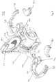
- Figure 6 shows various perspective and elevation views of a ratchet cuff 600.
- first arm 150, second arm 160 and lockable closure member 170 may comprise a ratchet cuff of the general form shown in figure 6 .
- Reference 602 shows a sectional view through the cuff. Cuff 602 is shown separately. When the ski locking device is assembled, cuff 602 can pivot, but would not be removed entirely as part of normal operation of the ski locking device.
- Pivot point 604 indicates a point on cuff 602 where it is connected either to the fixed portion of lockable closure member 170, or to the arm on which it is mounted. In use, cuff 602 pivots about point 604. Thickened portion 606 of cuff 602 corresponds to portion 566 of the cuff visible in figure 5 . See also figure 9 . Latch features 608 protrude above end portion 610, which extends from thickened portion 606.
- Figure 6 most closely describes the shapes of the second and third ratchet cuffs.
- the first ratchet cuff of lockable closure member 270 may, however, be slightly slimmer than portion 606 shown in figure 6 .
- the first ratchet cuff of lockable closure member 270 may also have indentations 608 along its entire convex surface, see for example figure 1 and the lowest part of figure 12 . Those indentations may be more closely spaced, i.e. have a finer pitch, than the latch portions at the ends of the second and third ratchet cuffs, as shown in figures 1 and 9-20 .
- FIG. 7 shows various perspective and elevation views of housing 700.
- Housing 700 shows the main component of the body of the lock as shown at reference 110 in figure 1 .
- the openings through which the pegs and teeth pass are visible, arrayed around the body of the housing.
- FIG 8 shows various perspective and elevation views of a cam lock 800.
- Front face 802 of cam lock 800 after assembly of the ski locking device, will sit at the front of the ski locking device.
- the remainder of cam lock 800 lies within housing 120.
- Front face 802 is visible in figure 1 , just above the point where reference 130 indicates the front portion of the housing 120.
- Rear portion 804 of cam lock 800 after assembly of the ski locking device, extends inside the housing 120.
- Rear portion 804 of cam lock 800 is not visible in any of figures 1-7 , and is not visible in normal operation of the ski locking device.
- slot 806 allows insertion and removal of a key, which is not shown on figure 8 .
- the later figures provide further description of the use of the key.
- FIG 9 shows a perspective view of ski locking device 900 in an inverted orientation.
- ski locking device is in an inverted orientation, relative to the orientation in figure 1 .
- ski locking device 900 is oriented with the lockable closure member 970 above the housing 910.
- Ski locking device 900 may then be used to lock a pair of skis, in an orientation with the lockable closure member above the housing.
- This contrasts with the orientation in figure 1 where the lockable closure member 170 is below the housing 110.
- the ski locking device would be used to lock a pair of skis, in an orientation with the lockable closure member 170 below the housing 110.
- front portion 930 of housing 910 corresponds generally to front portion 130 of housing 110 in figure 1 .
- First arm 950 corresponds to first arm 150 of figure 1 , but is to the right side of figure 9 , due to the inverted orientation of ski locking device 900 relative to figure 1 .
- Second arm 960 corresponds to second arm 160 of figure 1 , but is to the left side of figure 9 , due to the inverted orientation of ski locking device 900 relative to figure 1 .
- First ratchet cuff 974 pivots on the extremity of the fixed portion of lockable closure member 970. First ratchet cuff 974 is shown in the closed position in figure 9 . However, no ski-bindings are in the aperture 975 created within lockable closure member 970 in the configuration illustrated in figure 9 . First ratchet cuff 974 might, for example, be in the closed position shown in figure 9 when the ski locking device is not in use, and stowed away.
- First ratchet cuff 974 has indentations 978 along most of its convex surface. This allows first ratchet cuff 974 to be locked into place against main body 910 in a wide variety of orientations. At one extreme, just the distal, thin end of first ratchet cuff 974 may be inserted far enough to be locked against main body 910. At one extreme, the distal, thin end of first ratchet cuff 974 may be inserted so far that it protrudes down into the fixed portion of lockable closure member 970, in which case the aperture 975 becomes very small.
- first ratchet cuff 974 In this orientation, the last indentations on the convex edge of first ratchet cuff 974, at a point where first ratchet cuff 974 is thickest, will be locked against main body 910.
- the length of the convex edge of first ratchet cuff 974 that carries indentations 978 will determine the range of closed positions in which first ratchet cuff 974 can be locked. This, in turn, determines the range of sizes of aperture 975 for surrounding, and possibly holding fast, the ski bindings that lie within aperture 975 when lockable closure member 970 is the closed and locked position, in use.
- Second ratchet cuff 956 is shown mounted on first arm 950. Second ratchet cuff 956 is shown in the open position. The various details of second ratchet cuff 956 in figure 9 correspond to the design shown in figure 6 . Indentations 958 constituting latch features are visible on the convex outer edge of second ratchet cuff 956.
- Third ratchet cuff 966 is shown mounted on second arm 960. Third ratchet cuff 966 is shown in the open position. The various details of third ratchet cuff 966 in figure 9 correspond to the design shown in figure 6 . For example, thickened portion 906 of third ratchet cuff 966 is comparable to thickened portion 606 of ratchet cuff 602 in figure 6 . Pivot point 904 in figure 9 corresponds to pivot point 604 in figure 6 . Latch features 968 of third ratchet cuff 966 are also shown in each of the four views in figure 6 .
- third arm 960 carries a pad 963. When the ski locking device is used to lock ski poles, those poles will abut pad 963. This prevents damage both to the inner edge of third arm 960, and to the enclosed ski pole.
- the inner edge of second arm 950 carries a similar pad 953.
- Pole protection bumper 962 is shown disassembled from the remainder of ski locking device 900. Pole protection bumper 962 slides onto the inner edge of ratchet cuff 966, at the location of thickened portion 906. Pole protection bumper 962 prevents damage both to the inner edge of third arm 960, and to the enclosed ski pole. A similar pole protection bumper 952 is shown in front of second arm 950.
- the components shown in figures 1-9 are variously made from metals/alloys, and from non-metallic composite materials that have sufficient resilience.
- FIGS 10-20 form a sequence, which mainly describes the function and use of the ski locking device. This contrasts with figures 1-9 , which mainly describe the structure of the ski locking device.
- ski locking device will be described during various generally consecutive stages of its use.
- the starting position in figure 10 is with the ski locking device as it would normally be configured when it has been stored.
- Final figure 20 of this sequence shows the ski locking device locked around a pair of skis and poles.
- Tether 180 of the ski locking device is shown in figure 13 , but not in figures 10-12 and 14-21 .
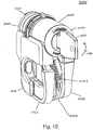
- FIG 10 is a perspective view of ski locking device 1000, from the front. Unlike previous views, figure 10 shows ski locking device 1000 from the side on which first arm 1050 is located. Figure 10 shows ski locking device as it would normally be configured when it has been stored. Thus figure 10 illustrates the configuration of ski locking device 1000, for example, when a user removes ski locking device 1000 from a pocket or rucksack, with the intention of using it to secure a pair of skis. Typically, a pair of ski poles would also be secured, and this application is also illustrated in the sequence of figures 10-20 .
- FIG. 10 shows housing 1020. Inserted into front portion 1030 of housing 1020 is a key 1032. Prior to turning key 1032, all the moveable components of ski locking device 1000 may be locked and immovable. Arrow 1034 indicates a direction in which a user will turn key 1032, in order to unlock ski locking device 1000. Key 1032 may be turned through 90 degrees, i.e. a quarter turn, in order to unlock ski locking device 1000. When ski locking device 1000 is unlocked the key is not removable. The key is only removable once the ski locking device has been locked.
- the ski locking device may be configured such that, when key 1032 turned through 180 degrees the first 1050 and second 1060 arms are unlocked, and at 270 degrees the central cuff is unlocked.
- first arm 1050 is visible.
- the first ratchet cuff of lockable closure member 1070 is also visible at the lower centre of figure 10 .
- Approximately seven of the indentations 1078 on the outer convex edge of the first ratchet cuff are also visible.
- Second ratchet cuff 1056 of first arm 1050 is also visible at the lower front of figure 10 .
- Third ratchet cuff 1066 is also visible at the lower right front of figure 10 .
- housing 1020 Towards the back of housing 1020, the rear portion 1040 of housing 1020 is visible. Central protruding portion 1042 is also just visible, projecting beyond rear portion 1040.
- first arm 1050 comprising second ratchet cuff 1056 is in the first storage position, lying adjacent to a first side of the lockable closure member 1070.
- Third ratchet cuff 1066 is visible in figure 10 , and indicates that the third ratchet cuff is in the second storage position, lying adjacent to a second side of the lockable closure member 1070.
- second ratchet cuff 1056 is generally shown in the first storage position, second ratchet cuff 1056 has been illustrated in a position where it has not been completely closed.
- a comparison of second ratchet cuff 1056 and third ratchet cuff 1066 in figure 10 shows that the bottom edge of second ratchet cuff 1056 is slightly lower than third ratchet cuff 1066. If second ratchet cuff 1056 were completely closed, second ratchet cuff 1056 and third ratchet cuff 1066 would lie symmetrically either side of lockable closure member 1070.
- FIG 11 is another perspective view of ski locking device 1100, from the front, and subsequent to that in figure 10 .
- Figure 11 shows ski locking device 1100 after key 1132 has been turned through 90 degrees. All moveable parts of ski locking device 1100 may now be unlocked. A user can therefore now start to move parts of ski locking device 1100 into the correct positions to lock up a pair of skis.
- a user has rotated first arm 1150 from the first storage position to a first deployed position.
- Arrow 1136 indicates the movement of first arm 1150 from the first storage position to the first deployed position.
- the user has also rotated second arm 1160 from the second storage position to the second deployed position.
- Arrow 1138 indicates the movement of second arm 1160 from the first storage position to the first deployed position.
- Indentations 1178 on the convex outer edge of first ratchet cuff 1170 are now more clearly visible. Approximately eight of indentations 1178 are visible in figure 10 .
- second ratchet cuff 1156 and third ratchet cuff 1166 are shown in a closed configuration. In this closed configuration, only the thickened part 606 (see again figure 6 ) of each of second ratchet cuff 1156 and third ratchet cuff 1166 is visible.
- Figure 12 is another perspective view of ski locking device 1200, from the front, and subsequent to that in figure 11 .
- Figure 12 illustrates the operation of opening the first-, second- and third ratchet cuffs.
- First ratchet cuff 1274 is now clearly visible. First ratchet cuff 1274 has moved in the direction shown by arrow 1271. This has involved rotation about an axis 1272. This rotation occurs around the point at which first ratchet cuff 1274 is attached to the remainder of lockable closure member 1270. All of lockable closure member 1270, except for first ratchet cuff 1274, may be rigidly attached to the lower edge of housing 1220.
- First ratchet cuff 1274 comprises indentations 1278.
- Indentations 1278 may run all the way to the distal end of first ratchet cuff 1274.
- the proximal part of first ratchet cuff 1274 that does not show indentations 1278 may also be of narrower width than portion 606 of the second and third ratchet cuffs as illustrated in figure 6 .
- Second ratchet cuff 1256 is now also clearly visible towards the left of figure 12 .
- Second ratchet cuff 1256 has moved in the direction shown by arrow 1251. This has involved rotation about an axis 1252. This rotation occurs around the point 1254 at which second ratchet cuff 1256 is attached to the remainder of first arm 1250.
- Second ratchet cuff 1256 comprises indentations 1258.
- Third ratchet cuff 1266 is now also clearly visible towards the right of figure 12 .
- Third ratchet cuff 1266 has moved in the direction shown by arrow 1261. This has involved rotation about an axis 1262. This rotation occurs around the point 1264 at which third ratchet cuff 1266 is attached to the remainder of second arm 1260.
- Second ratchet cuff 1266 comprises indentations 1268.
- Figure 13 provides a perspective view of the ski locking device when placed against a pair of skis.
- the configuration of the ski locking device itself in figure 13 corresponds generally to that shown in figure 12 .
- the skis themselves do not form part of the ski locking device. For this reason, the skis have been given reference numerals of the format '3XXX', in order to distinguish them from the reference numerals '1YYY' and '2YYY' used for components of the ski locking device throughout the drawings.
- First ski 3010 has a first edge 3012 and a non-sliding surface 3014.
- Surface 3014 is the upper surface of the ski, when the ski is placed on the ground for normal use.
- the sliding surface of first ski 3010 is not visible in figure 13 .
- First ski 3010 also has a first snow-brake 3040, which is visible in the lower part of figure 13 .
- First snow-brake 3040 has a first shoulder 3042.
- Second ski 3020 has a second edge 3022 and a sliding surface 3026. The non-sliding surface of second ski 3020 is not visible in figure 13 . Second ski 3020 also has a second snow-brake 3050, which is also visible in the lower part of figure 13 . Second snow-brake 3050 has a second shoulder 3052.
- First ski 3010 and second ski 3020 have been placed in their storage configuration. This means that the sliding surfaces of both skis face or abut each other. Typically, the sliding surfaces of the skis touch at their ends, but there may be a gap between the skis in their mid-portions, as is illustrated in figure 13 . Gap 3030 is shown towards the top of figure 13 . First snow-brake 3040 and second snow-brake 3050 cross at crossing point 3060.
- Front portion 1330 of the ski locking device is illustrated towards the front of figure 13 .
- Lockable closure member 1370 can be seen, but part of lockable closure member 1370 lies in gap 3030 between first ski 3010 and second ski 3020.
- First ratchet cuff 1374 lies generally above the crossing point 3060 of first snow-brake 3040 and second snow-brake 3050.
- central protruding portion 242 of housing 220 shown on figure 2 is not visible in figure 13 , as it has been pushed into gap 3030 between first ski 3010 and second ski 3020. In this situation, rear portion 240 shown in figure 2 now abuts first edge 3012 of first ski 3010, and second edge 3022 of second ski 3020. Central protruding portion 242 may help guide the ski locking device as a user moves it downwards or upwards, towards the point where the first ratchet cuff passes behind the crossing point of the ski brakes.
- First arm 1350 of the ski locking device may also abut first edge 3012 of first ski 3010.
- Second ratchet arm 1356 remains free to rotate, i.e. to open and close.
- Second arm 1360 may also abut second edge 3022 of second ski 3020.
- Third ratchet arm 1366 remains free to rotate, i.e. to open and close.
- central protruding portion 242 may lie between the slide surface of the first ski 3010 and the slide surface 3026 of the second ski 3020, when the ski locking device is in a closed position.
- central protruding portion 242 may not extend into the gap 3030 between the slide surface of the first ski 3010 and the slide surface 3026 of the second ski 3020, when the ski locking device is in a closed position.
- Tether 1380 is shown in figure 13 .
- Tether 1380 has first loop 1384 and second loop 1386, which correspond respectively to first loop 184 and second loop 186 of figure 1 .
- Tether 1380 is illustrated with third ratchet arm 1366 inserted through first loop 1384.
- the tether may be anchored on the top of the housing of the ski locking device, and rotate about a point at which the tether is anchored. Using this rotation, a user can move the tether to a position in which the user has access to the other parts of the ski locking device.
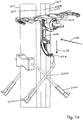
- Figure 14 provides a perspective view of the ski locking device when placed against a pair of skis, similar to that shown in figure 13 .
- the configuration of the ski locking device is the same as in figure 13 .
- Part of lockable closure member 1470 remains in the gap 3026 between first ski 3010 and second ski 3020.
- Rear portion 240 shown in figure 2 abuts first edge 3012 of first ski 3010, and second edge 3022 of second ski 3020.
- the central protruding portion 242 shown on figure 2 remains in gap 3030 between first ski 3010 and second ski 3020.
- Rear portion 240 shown in figure 2 abuts first edge 3012 of first ski 3010, and second edge 3022 of second ski 3020.
- Arrow 1434 indicates the direction of insertion of the ski locking device to bring it to the position shown in figures 13 and 14 .
- Arrow 1434 also indicates the direction of a force that a user may continue to apply to the ski locking device, in order to keep the rear portion of the housing against first edge 3012 of first ski 3010, and second edge 3022 of second ski 3020.
- Arrow 1436 indicates a direction in which the ski locking device will next move.
- a user will push the ski locking device downwards, in the direction of arrow 1436.
- the aim is to pass first ratchet cuff 1474 behind the crossing point 3060 of first snow-brake 3040 and second snow-brake 3050.
- the user may push the top of housing 1420 in order to move the ski locking device in the direction of arrow 1436.
- the user may also or instead grasp other portions of the ski locking device in order to apply a downward force to it.
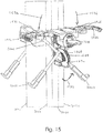
- Figure 15 provides a perspective view of the ski locking device locked around the crossing point 3060 of the snow-brakes.
- Main body 1510 of the ski locking device lies just above the crossing point 3060 of the snow-brakes.
- Main body 1510 lies close to or at the position of the first shoulder 3042 of first snow-brake 3040, and second shoulder 3052 of second snow-brake 3050, see again figure 13 .
- Arrow 1532 indicates the direction in which first ratchet cuff 1574 has pivoted.
- First ratchet cuff 1574 has passed behind, underneath and around the crossing point 3060 of first snow-brake 3040 and second snow-brake 3050.
- First ratchet cuff 1574 has engaged with the bottom of the main body 1510 of the ski locking device.
- the indentations 1578 visible on first ratchet cuff 1574 engage with a ratchet mechanism that is not visible in figure 15 , to hold first ratchet cuff 1574 in the position shown in figure 15 .
- Arrow 1534 indicates that the user may move first arm 1550 and second ratchet cuff 1556 downwards.
- Arrow 1536 indicates that the user may move second arm 1560 and third ratchet cuff 1566 downwards.
- first arm 1550 may be configured such that an edge of the first arm extends behind the first edge 3012 of the first ski 3010, and over a non-slide surface of the first ski.
- Second arm 1560 may be configured such that an edge of second arm 1560 extends behind the second edge 3022 of the second ski 3020 and over a non-slide surface of the second ski. This arrangement helps prevent separation of the skis, when the ski locking device is in a closed position locking a pair of skis.
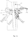
- Figure 16 provides a perspective view of the ski locking device locked around the crossing point of the snow-brakes. The view in figure 16 is subsequent to that in figure 15 .
- a first ski pole 3070 has been moved in the direction shown by arrow 1638. This movement placed first ski pole 3070 into the opening created by second ratchet cuff 1656. This can be understood from a comparison of the position of second ratchet cuff 1656, which is closed in figure 16 , with the position of second ratchet cuff 1556 in figure 15 .
- Arrow 1639 indicates a direction in which second ratchet cuff 1656 has pivoted about the point 1604 where it is attached to the remainder of first arm 1650.
- Second ratchet cuff 1656 has engaged with the remainder of first arm 1650 of the ski locking device.
- the indentations of second ratchet cuff 1656 have engaged with a ratchet mechanism that is not visible in figure 16 , i.e. second tooth 326 in figure 3 , to hold second ratchet cuff 1656 in the position shown in figure 16 .
- the indentations are illustrated as reference 608 on figure 6 and as reference 958 on figure 9 , for example.
- Third ratchet cuff 1666 remains open and unlocked.
- the remainder of second arm 1660 remains in the position shown in figures 14 and 15 .
- Figure 17 provides a perspective view from below of the ski locking device in the configuration of figure 16 . However, for clarity, the first ski pole has been omitted from figure 17 .
- Second ratchet cuff 1756 remains closed. Indentations 1755 on second ratchet cuff 1756 are visible on figure 17 .
- Second tooth/peg 1726 is also visible on housing 1720 of the ski locking device. Second tooth 1726 corresponds to second tooth 226 shown in figure 3 . A clearer view of the form of second tooth 1726 is visible from first actuator 222 in figure 2 , although second tooth 1726 is located on the opposite side of housing 1720 than first tooth 222 shown in figure 2 .
- Second tooth 1726 has engaged with the indentations 1755 on second ratchet cuff 1756, to hold second ratchet cuff 1756 in position.
- First shoulder 3042 of first snow brake 3040 may help to prevent movement of the ski locking device downwards, since first arm 1750 may be blocked by first shoulder 3042.
- first ratchet cuff 1774 and second ratchet cuff 1756 would both be locked. Second tooth 1726 would then be locked rigidly into position, and could not be depressed radially inwards towards housing 1720 to allow passage of indentations 1755 over it.
- second tooth 1726 can be depressed radially inwards towards housing 1720, to allow indentations 1755 and second ratchet cuff 1756 to pass freely in either direction.
- second tooth 1726 is only held in position by a spring force, which can easily be overcome by a user pulling or pushing second ratchet cuff 1756.
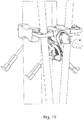
- Figure 18 provides another perspective view of the ski locking device locked around the crossing point of the snow-brakes.
- Figure 18 illustrates the closing of third ratchet cuff 1866 around a second ski pole 3072.
- Figure 16 shows an action similar to that in figure 16 .
- Second ski pole 3072 has been moved in the direction shown by arrow 1838. This movement placed second ski pole 3072 into the opening created by third ratchet cuff 1866.
- This can be understood from a comparison of the position of third ratchet cuff 1866 with the position of third ratchet cuff 1566 shown in figure 15 and third ratchet cuff 1666 shown in figure 16 .
- Arrow 1839 indicates a direction in which third ratchet cuff 1866 has pivoted about the point where it is attached to the remainder of second arm 1860.
- Third ratchet cuff 1866 has engaged with the remainder of second arm 1860 of the ski locking device.
- the indentations of second ratchet cuff 1866 have engaged with a ratchet mechanism that is not visible in figure 18 , to hold second ratchet cuff 1866 in the position shown in figure 18 , i.e. with third tooth 322 visible in figure 3 .
- the indentations are illustrated as reference 608 on figure 6 and reference 968 on figure 9 .
- Figure 19 shows the action of locking the ski locking device.
- Key 1932 has been turned through a quarter turn in the direction shown by arrow 1932 (clockwise). Key 1932 can be removed, when oriented as shown in figure 19 .
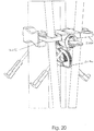
- Figure 20 illustrates the locked state of the moving parts of the ski locking device.
- First ratchet cuff 2074 is now locked in position.
- Second ratchet cuff 2056 is now locked in position.
- Third ratchet cuff 2066 is now locked in position.
- the single quarter turn of key 1932 shown in figure 19 simultaneously locks each of the three ratchet cuffs.
- the configuration of the ski locking device shown in figure 20 is the final configuration.
- the skis are locked to each other.
- Each of the ski poles is also locked.
- the triple locking action ensures that it would require tremendous force to remove the ski locking device.
- a user would have great difficulty gaining 'purchase' on the device, in order to try and exert any force on it.
- close component tolerances for the constituent parts of the ski locking device ensure that it is very difficult to rock or build up momentum in any attempt to twist the ski lock off.
- Tether 1380 shown in figure 13 may be used to secure the locking device and locked skis and poles to another object, which is preferably an immovable object.
- tether 1380 may be passed around a ski rack.
- first loop 1384 and second loop 1386 may be placed into one of the open arms 1350 or 1360, or possibly the lockable closure member 1370.
- first loop 1384 and second loop 1386 will also be locked in place.
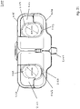
- Figure 21 shows a plan view of the ski locking device 2100.
- First arm 2150 and second arm 2160 have been rotated from the first and second storage positions into the deployed position. This movement is shown by arrows 1136 and 1138 in figure 11 .
- Second ratchet cuff 2156 and third ratchet cuff 2166 are in the closed positions.
- a second aperture 2159 provides an opening in which a ski pole of up to a diameter of 19mm may be located.
- a third aperture 2169 provides an opening in which a ski pole of up to a diameter of 19mm may be located.
- Pad 2163 and pole protection bumper 2162 correspond to pad 963 and pole protection bumper 962 in figure 9 .
- pole protection bumper 2162 has been illustrated in an assembled configuration, where pole protection bumper 2162 has been placed onto third ratchet cuff 2166. This is in contrast to the dis-assembled configuration, illustrated in figure 9 .
- Pad 2163 and pole protection bumper 2162 may help to prevent damage to a ski pole located in third aperture 2169.
- pole protection bumper 2152 has been illustrated in an assembled configuration, where pole protection bumper 2152 has been placed onto second ratchet cuff 2156. This is in contrast to the dis-assembled configuration, illustrated in figure 9 .
- Pad 2153 and pole protection bumper 2152 may help to prevent damage to a ski pole located in second aperture 2159.
- Protruding portion 2142 of the ski locking device 2100 is visible at the lower edge of figure 21 .
- Protruding portion 2142 corresponds to protruding portion 242 of figure 2 .
- Figure 22 shows a rear perspective view of the ski locking device 2200.
- First insert 2201 is shown disassembled from first arm 2250.
- First insert 2201 may be fitted into the outer edge of the fixed portion of first arm 2250.
- second insert 2203 is shown disassembled from second arm 2260.
- Second insert 2203 may be fitted into the outer edge of the fixed portion of second arm 2260.
- First insert 2201 and second insert 2203 may form the contact surfaces between ski locking device 2200 and the edges of the skis to which ski locking device 2200 is fitted. This arrangement of first insert 2201 prevents direct metal to metal contact between first arm 2250 and the ski that abuts or lies behind the fixed portion of first arm 2250.
- second insert 2203 prevents direct metal to metal contact between second arm 2260 and the ski that abuts or lies behind the fixed portion of second arm 2260. A consequence may be less wear on the ski locking device 2200 and on the skis to which it is attached.
- First insert 2201 if made of plastic, rubber or other material that is a poor thermal conductor and/or is soft, may provide an enhanced feel to ski locking device 2200 for the user.
- Figure 23 illustrates a perspective view of the ski locking device locked around the crossing point of the snow-brakes, in an inverted orientation.
- the orientation shown in figure 23 corresponds to that in figure 9 .
- the locked configuration of the arms of the ski locking device in figure 23 is comparable to the locked configuration illustrated in figure 20 .
- Figure 23 illustrates the locked state of the moving parts of the ski locking device, in the inverted orientation.
- First ratchet cuff 2374 is now locked in position.
- Second ratchet cuff 2356 is now locked in position.
- Second ratchet cuff 2356 is towards the lower right of figure 23 , in contrast to the location of second ratchet cuff 2056 in figure 20 .
- Third ratchet cuff 2366 is now locked in position.
- Third ratchet cuff 2366 is towards the lower left of figure 23 , in contrast to the location of third ratchet cuff 2056 in figure 20 .
- Figure 24 illustrates a cross-sectional, side elevation view of the interior of ski locking device 2400.
- Figure 24 may be compared to figure 17 , which shows the first ratchet cuff 1774 of the lockable closure member locked against the underside of the main housing 1720 of the ski locking device.
- the upper centre of figure 24 shows a cross section of the cam lock 2408, which was shown as a separate component in figure 8 .
- Key 2432 is shown in cross section, towards the right of figure 24 .
- Third ratchet cuff 2466 of the second arm 2460 is illustrated in the locked in position at the upper right of figure 24 .
- First ratchet cuff 2474 of the lockable closure member 2470 is illustrated below the underside of the main housing 2410 of the ski locking device. First ratchet cuff 2474 is locked against the underside of the main housing 2410. Indentations 2478 on the convex outer edge of first ratchet cuff 2474 have been engaged by tooth 2479. Tooth/peg 2479 protrudes from the lower surface of main housing 2410 of ski locking device 2400.
- first ratchet cuff 2474 When the cam lock 2408 is unlocked, tooth 2479 can rise into main housing 2410. This allows the indentations 2478 on the convex surface of first ratchet cuff 2474 to pass in either direction. This allows the first ratchet cuff 2474 to open or close. Whilst first ratchet cuff 2474 is free to move, a user of the ski locking device may, by moving first ratchet cuff 2474, set the size of the space 2475 enclosed by the fixed portion of lockable closure member 2470 and the inner concave edge of first ratchet cuff 2474.
- the ski locking device When the user is satisfied with the size of the space 2475, the ski locking device can be locked by rotation of key 2432. In the locked configuration, tooth 2479 is locked into position, engaging one of the indentations 2478. The indentations 2478 on the convex surface of first ratchet cuff 2474 can no longer pass in either direction. This first ratchet cuff 2474 can, as a consequence, no longer move.
- the cam when the key 2432 is in the open (unlocked) position, the cam is moved to a position which allows tooth 2479 to depress as the first ratchet cuff 2474 cuff is rotated across the top of tooth 2479.
- the unlocked position of the key 2432 also allows the two teeth that are engaged with the second and third ratchet cuffs to move, so that the second and third ratchet cuffs can move over them.
- the cam prevents movement of the teeth, and therefore locks all the ratchet cuffs.
- the ski locking device may provide one or more of several additional operational features of value to a user. These may include:
Landscapes
- Engineering & Computer Science (AREA)
- Structural Engineering (AREA)
- Fittings On The Vehicle Exterior For Carrying Loads, And Devices For Holding Or Mounting Articles (AREA)
- Lock And Its Accessories (AREA)
Description
- The present invention relates to a portable locking device. In particular, the portable locking device may be configured for securing snow skis, and may also secure snow poles.
- Skis are occasionally lost to theft or unintentional mix up, when left unattended in ski resorts. This may happen, for example, outside mountain restaurants and cafes, where many hundreds of pairs of skis may be deposited from time to time. It is also possible in hotel ski/boot rooms, and outside village bars and restaurants.
- Portable security devices have therefore been developed for the ski market. These include, for example, cable or chain combination locks. Some known locks enable one or more snowboards or sets of skis to be secured together and/or to other permanent fixings such as a ski rack or the like. Such locks tend to be marketed as ski locks, but many are in fact generic combination cable or chain locks, which may be used for securing other portable high value items such as bicycles and luggage.
- Dedicated ski locks have been developed, including for example locks of the type disclosed in
US4111015 . InUS4111015 , the skis are locked in a crossed position so as to discourage theft when left unattended for short periods of time. The ski lock disclosed inUS4111015 comprises male and female brackets, which are secured to respective skis for mutual engagement and disengagement. A combination lock is provided on one of the brackets. The male and female security brackets are attached to the upper surface of the skis adjacent the bindings, so that the skis may be locked together in an X configuration.US4057983 provides a hinged clamp, for locking skis together.US4146242 also provides a two-part lock for a pair of skis, and the two parts may be connected by a hinge. -
EP1176274 A2 provides a wire cable for locking a pair of skiis. A flange is attached to each end of the wire cable. When the wire cable is fitted around a pair of skiis, the two flanges meet. A pin holds the flanges together, and is held fast by a lock portion. - German utility model
DE202008007377 U1 (Prestele )) shows a ski lock that is permanently attached to a ski or snowboard. DE'377 shows the arrangement of a base plate that is attached to an upper surface of one ski. Without disassembly of the binding, there is no possibility of forcefully removing the base plate and thereby the whole locking arrangement from the ski. DE'377 holds a flexible steel cable in a wound configuration inside a housing of the lock. When in use, the steel cable of DE'377 passes through a hole in the second ski. The free end of the cable is configured as a rod. The rod should be at least as long as the through-hole of the second ski. In order to accommodate this feature, the winding is located inside the housing of the lock sufficiently far from the opening through which cable flows, that the entire rod can sit within the housing. - Other arrangements are shown in
WO2011/101220 A1 (Zencom Telecommunications), andDE1933381 A1 (Marker Hannes ) andUS4146242 B1 (Bose ). - There are various disadvantages associated with these types of ski lock, particularly since the intention is just to discourage theft when the skis are left unattended in a ski resort. Many ski locks do not provide security for the ski poles. Nor can they be used to provide additional security, by enabling the skis to be secured to fixed structures.
- According to a first aspect of the invention there is provided a ski locking device in accordance with appended
claim 1. According to a second aspect of the invention there is provided a method of locking a pair of snow skis and/or ski poles in accordance with appended claim 14. - In the ski locking device, different elements of the device are provided for securing both the ski poles and the skis. The locking device has the advantage of being portable. When the ski locking device
is in the closed position locking the pair of skis, a space enclosed by a lockable closure member may be of an adjustable size. - A main body of the ski locking device comprises a housing. The lockable closure member may comprise a first ratchet cuff with indentations, the first ratchet cuff being configured to be pivotable about a pivot point. The first ratchet cuff may engage with a first ratchet mechanism. When the lockable closure member is in the closed position, the first ratchet mechanism is configured to engage with an indentation on the first ratchet cuff, to lock the lockable closure member. The first ratchet mechanism may comprise a first tooth, comprised of a sprung peg, which is located at the lower part of the housing. When the ski locking device is locked, the first tooth may be operable to lock into position in contact with one of the indentations on the first ratchet cuff, thereby preventing further movement of the first ratchet cuff.
- The ski locking device may further comprise a first arm comprising a second ratchet cuff, the first arm being moveable, and being configured to rotate from a first storage position to a first deployed position. The ski locking device may further comprise a second arm comprising a third ratchet cuff, the second arm being moveable, and being configured to rotate from a second storage position to a second deployed position. When the first arm is in the first storage position, the first arm lies adjacent to a first side of the lockable closure member. When the second arm is in the second storage position, the second arm lies adjacent to a second side of the lockable closure member.
- When the first arm is in the first deployed position, the second ratchet cuff is operable to lock around a first ski pole. When the second arm is in the second deployed position, the third ratchet cuff is operable to lock around a second ski pole. The second ratchet cuff further comprises second indentations serving as latch features. The second indentations engage with a tooth mounted on a first side of the housing, the first arm being on the first side of the housing when in the first deployed position. The third ratchet cuff further comprises third indentations that also serve as latch features. The third indentations engage with a tooth mounted on a second side of the housing, the second arm being on the second side of the housing when in the second deployed position.
- The housing and the lockable closure member may be configured such that, when the ski locking device is in the closed position locking the pair of skis, with the slide surface of the first ski facing the slide surface of the second ski, the rear portion of the housing abuts the first edge of the first ski and the second edge of the second ski. The rear portion of the housing has a central protruding portion. When the separation between the edges of the skis and the crossing point of the snow brakes is relatively small, the central protruding portion may lie between the slide surface of the first ski and the slide surface of the second ski, when the ski locking device is in a closed position. The central protruding portion may help guide the ski locking device as a user moves it along the edges of the skis, towards the point where the first ratchet cuff passes behind the crossing point of the ski brakes.
- A cylinder cam lock within the housing is operable to lock the locking device, by locking into position the multiple teeth protruding from the outer surface of the housing. One tooth may then engage with and retain the first ratchet cuff, another tooth may engage with and retain the second ratchet cuff, and another tooth may engage with and retain the third ratchet cuff.
- Various embodiments of the invention will now be more particularly described, by way of example only, with reference to the accompanying drawings.
Figures 1-9 are primarily focussed on the structure of the ski locking device.Figures 10-21 are primarily focussed on the function of the ski locking device. -
Figure 1 is a perspective view of a ski locking device according to an embodiment of the invention. -
Figure 2 is a lateral perspective view of the ski locking device, with the locking device in the stowed configuration. -
Figure 3 is a front and side perspective view of the ski locking device, in close-up, with the tether removed. -
Figure 4 is a side elevation view of the ski locking device, with the tether attached. -
Figure 5 is a perspective view of an arm of the ski locking device, which is shown separately from the remainder of the ski locking device. -
Figure 6 shows various perspective and elevation views of a ratchet cuff of the ski locking device, which is shown separately from the remainder of the ski locking device. -
Figure 7 shows various perspective and elevation views of the housing, which is shown separately from the remainder of the ski locking device. -
Figure 8 shows various perspective and elevation views of a cam lock, which is shown separately from the remainder of the ski locking device. -
Figure 9 is a perspective view of the ski locking device in an inverted orientation, with the second and third ratchet cuffs open. -
Figure 10 is a perspective view of the ski locking device, from the front. -
Figure 11 is another perspective view of the ski locking device, from the front. -
Figure 12 is another perspective view of the ski locking device, from the front. -
Figure 13 provides a perspective view of the ski locking device when placed against a pair of skis. -
Figure 14 provides another perspective view of the ski locking device when placed against a pair of skis. -
Figure 15 provides a perspective view of the ski locking device locked around the crossing point of the snow-brakes. -
Figure 16 provides a perspective view of the ski locking device locked around the crossing point of the snow-brakes. -
Figure 17 provides a perspective view from below of the ski locking device in the configuration offigure 16 . -
Figure 18 provides another perspective view of the ski locking device locked around the crossing point of the snow-brakes. -
Figure 19 shows the action of locking the ski locking device. -
Figure 20 illustrates the locked state of the moving parts of the ski locking device. -
Figure 21 illustrates a plan view of the ski locking device. -
Figure 22 illustrates a rear perspective view of the ski locking device. -
Figure 23 illustrates a perspective view of the ski locking device locked around the crossing point of the snow-brakes, in an inverted orientation. -
Figure 24 illustrates a cross-sectional, side elevation view of the interior of the ski locking device. - A ski locking device for securing a pair of snow skis comprises a housing having a rear portion. A lockable closure member is connected to the housing. The housing and the lockable closure member are configured such that, when the ski locking device is in a closed position locking a pair of skis, with a slide surface of the first ski facing a slide surface of the second ski: the rear portion of the housing faces a first edge of the first ski and a second edge of the second ski; and the lockable closure member encloses the snow brakes at a crossing point of the snow brakes.
- The figures show details of the ski locking device of the invention. The locking device may, advantageously, be hand portable. When skiing, the locking device may therefore be stowed in a pocket or small rucksack.
- The invention provides a locking device that serves as a lock for securing an abutted pair of skis. The locking device may also secure two ski poles. A secondary tether allows the locking device to be releasably attached to a permanent structure. The locking device can therefore serve as an anti-theft device for both skis and ski poles. A mechanical lock and key may be operable down to two-digit sub-zero temperatures.
- The locking device utilises the point where the snow brakes of a pair of skis overlap, when two skis are abutted together. By locking a central locking member around the snow brake crossing point, which constitutes a 'central point' of the pair of skis when placed together, the locking device prevents the skis from being pulled apart. The central locking member locks around the snow brake crossing-point by means of a ratchet mechanism similar to a hand-cuff. The space enclosed by the cuff, in the closed position, is adjustable in size to accommodate different snow brake arrangements.
- In addition to the central locking member, two further arms are used to lock the ski poles. These arms have ratchet cuffs. When in an open position, a pole can be inserted into each. The poles can then be locked individually, aligned with the skis. When not in use, the pole locking arms can each be rotated down to a storage position. The pole locking arms then lie either side of the central locking member, to be flush with the central cuff. The space enclosed by each of the cuffs can be adjusted in size by a ratchet mechanism. All three are locked in place with a single locking point.
- The lock may also be supplied with a flexible, curly, coiled tether. This is used in combination with the interlocking cuffs to secure the skis and poles to a more secure anchor, such as a ski rack. The tether may be a separate tether, comprising a closed loop at either end. In operation, the ski locking device can be fastened to another object by passing the tether around the object, and enclosing each closed loop of the tether in one of the second ratchet cuff and the third ratchet cuff. The loops of the tether may be enclosed in the first ratchet cuff of the lockable closure member, but this may be less advantageous than enclosing each closed loop in one of the second ratchet cuff and the third ratchet cuff. The tether may also be used in a configuration similar to a lasoo. In this arrangement, one loop of the tether is pushed through the other loop, to create a noose. Then only the end of the loop that was pushed through the other loop needs to be enclosed in one of the second ratchet cuff and the third ratchet cuff.
- In an alternative arrangement, one end of the tether may be attached to the main body of the lock. The opposite end of the tether then has a loop which can be attached to either of the cuffs, once looped around the secure anchor. The tether can still be replaced if worn, or if the consumer wishes to have a customised look. This is achieved through an interlocking feature on the body of the main lock, whereby the tether can only be removed when the lock is in the open position.
- The ski lock may use a modified 'cylinder cam' type lock. A flat plate pawl of a known cylinder cam lock may be replaced with a bespoke cam. The cuff ratchets engage with sprung pegs, which protrude from the housing of the ski locking device. When the key is in the open (unlocked) position, the cam is moved to a position which allows the pegs to depress as the cuffs are rotated across the tops of them. However, when the key is locked, the cam restricts the pegs' movement, and therefore locks the ratchet cuffs. The sprung pegs may also be termed 'teeth'. The cylinder cam lock within the housing is therefore operable to lock the locking device, by locking into position the multiple sprung pegs/teeth protruding from the outer surface of the housing, whereby a first tooth locks into position to prevent movement of the ratchet cuff of the lockable closure member, a second tooth locks into position to prevent movement of the second ratchet cuff, and a third tooth locks into position to prevent movement of the third ratchet cuff.
- With the ski locking device, an advantageous mutual orientation of the clamp parts may be provided, when they are in the deployed position. The ski locking device can be used to lock a pair of skis with the snow brakes in their crossed, stored position. The device may be manipulated easily between the deployed condition, and the compact, stowed position.
- Notably, the ski locking device offers a three point security system. A first ratcheted cuff secures interlocking snow brakes on abutted skis, and two further cuffs secure ski poles either side of the locking cylinder. A secondary tether allows the ski locking device to be secured to a permanent fixture, for example a ski rack, post or roof rack. The secondary tether may be a coiled, plastic coated galvanised cable, which can be removed entirely from the device, to facilitate separate storage.
- The ski locking device may be applied to a pair of skis, in one of two different orientations. Firstly, the ski locking device may be placed in a closed position, locking a pair of skis, oriented with the lockable closure member below the housing. In this case, the second ratchet cuff is closable by movement in an anti-clockwise direction, when viewed from above, and the third ratchet cuff is closable by movement in a clockwise direction, when viewed from above. Alternatively, the ski locking device may be placed in a closed position, locking a pair of skis, oriented with the lockable closure member above the housing. In this case, the second ratchet cuff is closable by movement in a clockwise direction, when viewed from above. The third ratchet cuff is closable by movement in an anti-clockwise direction, when viewed from above. The orientation with the lockable closure member above the housing is referred to as an 'inverted' orientation in the description. However, either orientation may be used. The term 'inverted' orientation has been chosen for the orientation with the lockable closure member above the housing, which is shown in two of the drawings, because the majority of the drawings show the orientation with the lockable closure member below the housing.
- Once secured on the snow brakes, with poles and tether latched in place, the ski locking device can be used to carry all the ski equipment. Alternatively or in addition, the ski locking device may facilitate transportation on a roof rack or in storage area of a vehicle.
- The ski locking device may offer some or all of the following advantages:
- (i) The device is portable, and in its stowed position readily stored in a ski jacket pocket.
- (ii) Utilising a three-point security system, the ski locking device secures: a pair of skis in an abutted arrangement at the point that their snow brakes interlock; two ski poles; and provides the optional use of a secondary tether.
- The ski locking device is deployable on a range of different snow skis and ski poles. It may be applied, potentially, on snowboards, cycles, luggage, or on any item of equipment/kit that would benefit from multiple locking points and a secondary tether.
- The second ratchet cuff and the third ratchet cuff may be identical. In this case, when manufacturing the ski locking device, the second ratchet cuff is mounted to the housing in an inverted orientation relative to the third ratchet cuff. A raised lip may run around an outer curved edge of the second and third ratchet cuffs. The raised lip provides an edge for a user to pull against when opening the ratchet cuff.
- A first flexible pole bumper element may lie in the inner edge of the second ratchet cuff. A second flexible pole bumper element may lie in the inner edge of the third ratchet cuff.
- The ski locking device may further comprise an alarm function, operable to provide an alarm indication when the tether has been cut. The alarm function may be implemented as an app on a processor means within the ski locking device, the alarm function operable to generate and send a text message as the alarm indication that the tether has been cut. The ski locking device may further comprise a fingerprint recognition subsystem, the fingerprint recognition subsystem being operable to unlock the ski locking device.
- The ski locking device may further comprise a light finder subsystem, the light finder subsystem illuminating a portion of the ski locking device in response to a signal from a user of the ski locking device. A light finder subsystem may be integrated into the tether, the light finder subsystem illuminating a portion of the tether in response to a signal from a user of the ski locking device. The signal may be one of a transmitted signal from a key fob device comprising a battery, the key fob device being activated by a user, or a voice signal from the user.
- The ski locking device may further comprise a solar cell forming part of the ski locking device, the solar cell operable to provide energy to the ski locking device. The solar cell may form part of the tether.
- The ski locking device may further comprise a temperature measurement function, whereby in operation a temperature indication may be provided to a user of the ski locking device. A temperature indication may be provided as operation of, or a change to a colour of, an illumination function of the ski locking device. The ski locking device may further comprise a GPS locator app, whereby in operation the GPS locator app transmits an indication of the location of the ski locking device, remotely, to a user.
- Throughout the drawings, corresponding elements have been given similar reference numerals where possible.
-
Figure 1 is a perspective view of a ski locking device 100 according to an embodiment of the invention. Ski locking device 100 includes amain body 110. Themain body 110 comprises several parts, of whichhousing 120 is indicated onFigure 1 . Afront portion 130 ofhousing 120 is visible onFigure 1 . -
First arm 150 andsecond arm 160 extend from either side ofhousing 120.First arm 150 andsecond arm 160 are moveable with respect tohousing 120, as will be illustrated and explained in subsequent figures. A firstlockable closure member 170 extends from the lower surface ofhousing 120. - Locking device 100 also comprises a
tether 180. Tether 180 does not form part of the main body 100 of the locking device. Tether 180 may be flexible. Tether 180 comprises a curledportion 182, which may be reversibly uncoiled by pulling. Tether 180 also comprisesfirst loop 184 andsecond loop 186. Whenfirst loop 184 is pulled in a direction away frommain body 110 withsecond loop 186 held by one of the ratchet cuffs, curledportion 182 may uncurl, allowingfirst loop 184 to reach a point far frommain body 110. When the pull force onfirst loop 184 is removed,tether 180 may then return to the configuration shown inFigure 1 . -
Figure 2 is a lateral perspective view of theski locking device 200. Infigure 2 ,ski locking device 200 has been rotated relative to the view shown infigure 1 . In addition,ski locking device 200 is shown in the stowed configuration. The stowed configuration ofski locking device 200 is the configuration whenski locking device 200 is not in use. The compact configuration ofski locking device 200 results inski locking device 200 being easy to transport, as can be seen infigure 2 . -
Housing 220 ofski locking device 200 corresponds to housing 120 offigure 1 . Firstlockable closure member 270 corresponds to firstlockable closure member 170 offigure 1 . Infigure 2 , firstlockable closure member 270 is almost entirely concealed bysecond arm 260. -
First arm 250 is shown in a first storage position. In the first storage position,first arm 250 lies adjacent to a first side oflockable closure member 270.Second arm 260 is shown in a second storage position. In the second storage position,second arm 260 lies adjacent to a second side oflockable closure member 270. In the view shown infigure 2 ,second arm 260 is nearest to the viewer's location. Slightly further from the viewer's location islockable closure member 270. Furthest from the viewer's location isfirst arm 250. -
Housing 220 has a rear portion, which is generally indicated byreference numeral 240. Throughout the drawings, the end of thehousing 220 that reference numeral 240 contacts inFIG. 2 , will be referred to as therear portion 240. The opposite end ofhousing 220 is thefront portion 130, referred to infigure 1 . -
Rear portion 240 ofhousing 220 has a protrudingportion 242. Protrudingportion 242 is located towards the mid-point ofrear portion 240. Protrudingportion 242 may extend down therear portion 240 from the top of the housing. Protrudingportion 242 may join with or form the rear part oflockable closure member 270, i.e. extend all the way to the lowest point at the rear of thehousing 220. - Also shown on
figure 2 isthird tooth 222. The purpose ofthird tooth 222 will be described subsequently, in the later figures that describe the operation ofski locking device 200.Third tooth 222 is spring loaded.Third tooth 222 may be depressed radially, in towards the centre line ofhousing 220, whenski locking device 200 is unlocked. Whenski locking device 200 is locked,third tooth 222 is fixed, and can no longer be depressed. -
Figure 3 is a front and side perspective view ofski locking device 300, in close-up. As infigure 2 ,ski locking device 300 is shown in the stowed configuration.Lockable closure member 370 is more clearly visible infigure 3 .First arm 350 lies adjacent to a first side oflockable closure member 370. Second arm 360 lies adjacent a second side oflockable closure member 370. - The upper surface of part of a
first mounting ring 352 is shown infigure 3 . First mountingring 352 is attached tofirst arm 350. First mountingring 352 extends around the circumference ofhousing 320, and is rotatable aroundhousing 320. Thusfirst arm 350 may move up from the first storage position shown infigure 3 , for example to the orientation shown forfirst arm 150 infigure 1 . First mountingring 352 will rotate aroundhousing 320, as this movement occurs. - The upper surface of part of a
second mounting ring 362 is also shown infigure 3 . Second mountingring 362 is attached to second arm 360. Second mountingring 362 extends around the circumference ofhousing 320, and is rotatable aroundhousing 320. Thus second arm 360 may move up from the second storage position shown infigure 3 , for example to the orientation shown forsecond arm 160 infigure 1 . Second mountingring 362 will rotate aroundhousing 320, as this movement occurs. - Also visible on
figure 3 arethird tooth 322 andsecond tooth 326.Third tooth 322 corresponds tothird tooth 222 onfigure 2 .Second tooth 326 is positioned on the same side of the housing asfirst arm 350, which is the opposite side ofhousing 320 tothird tooth 222 infigure 2 .Second tooth 326 is moveable, as explained in relation tothird tooth 222. -
Figure 4 is a side elevation view ofski locking device 400.Figure 4 is designed to provide exemplary dimensions forski locking device 400. - The following examples of dimensions for
ski locking device 400 are non-limiting: - (i) Length x of
main body 410 may be in the range 4cm - 15cm. In a preferred embodiment, length x may be 6.5 cm; - (ii) Height h of
main body 410 may be in the range 4cm - 15cm. In a preferred embodiment, height h may be 6.5 cm; - (iii) Length I of
tether 480, when not stretched, may be in the range 8cm - 50cm. In a preferred embodiment, length I may be 15cm. - When
tether 480 is stretched, it may extend to a length in the range 40cm - 1.5 metres. In a preferred embodiment,tether 480 may extend to 90cm. In an embodiment wheretether 480 does not comprise a curledportion 482, its rest length may be in the range 40cm - 2 metres. -
Figure 5 is a perspective view ofsecond arm 560.Second arm 560 is shown separately fromhousing 220. When the ski locking device is assembled,second arm 560 is mounted onhousing 220, and would not be removed as part of normal operation of the ski locking device. Second mountingring 562 is now clearly visible in its entirety. - Also visible on
figure 5 is lockingpin 564. A spring pushes lockingpin 564 out from the centre of the ski locking device. Lockingpin 564 lies under thethird tooth 222, and controls whether thethird tooth 222 is locked into position. Lockingpin 564 co-operates with the indentations or 'latch features' on the ratchet cuff. These are the latch features shown infigure 6 . When the ski locking device is in the unlocked state, lockingpin 564 is free to move in towards the centre of thehousing 220. In this unlocked condition, the indentations on the ratchet cuff that contact the top of the tooth are allowed to bump past the tooth, as a user pushes or pulls the ratchet arm. The indentations are the latching features on the ratchet. When the ski locking device is in the locked state,pin 564 is prevented from travelling into the body.Pin 564 therefore stays securely located in the latch features of the ratchet cuff, thereby preventing the cuff from being opened. - Part of
second arm 560 comprises asecond cuff 566. Only part ofsecond cuff 566 is visible infigure 5 . Parts ofsecond cuff 566 that are not visible infigure 5 are concealed withinsecond arm 560, to whichsecond cuff 566 is moveably attached. - Although not shown in
figure 5 ,first arm 350 infigure 3 is of comparable construction tosecond arm 560.First arm 350 and first mountingring 352 are a mirror image ofsecond arm 560 and second mountingring 562. The main body of the ski locking device has a locking pin corresponding to lockingpin 564 shown onfigure 5 engagingsecond arm 560. -
Figure 6 shows various perspective and elevation views of aratchet cuff 600. Each offirst arm 150,second arm 160 andlockable closure member 170 may comprise a ratchet cuff of the general form shown infigure 6 . -
Reference 602 shows a sectional view through the cuff.Cuff 602 is shown separately. When the ski locking device is assembled,cuff 602 can pivot, but would not be removed entirely as part of normal operation of the ski locking device. -
Pivot point 604 indicates a point oncuff 602 where it is connected either to the fixed portion oflockable closure member 170, or to the arm on which it is mounted. In use,cuff 602 pivots aboutpoint 604.Thickened portion 606 ofcuff 602 corresponds toportion 566 of the cuff visible infigure 5 . See alsofigure 9 . Latch features 608 protrude aboveend portion 610, which extends from thickenedportion 606. -
Figure 6 most closely describes the shapes of the second and third ratchet cuffs. The first ratchet cuff oflockable closure member 270 may, however, be slightly slimmer thanportion 606 shown infigure 6 . The first ratchet cuff oflockable closure member 270 may also haveindentations 608 along its entire convex surface, see for examplefigure 1 and the lowest part offigure 12 . Those indentations may be more closely spaced, i.e. have a finer pitch, than the latch portions at the ends of the second and third ratchet cuffs, as shown infigures 1 and9-20 . -
Figure 7 shows various perspective and elevation views ofhousing 700.Housing 700 shows the main component of the body of the lock as shown atreference 110 infigure 1 . The openings through which the pegs and teeth pass are visible, arrayed around the body of the housing. -
Figure 8 shows various perspective and elevation views of acam lock 800.Front face 802 ofcam lock 800, after assembly of the ski locking device, will sit at the front of the ski locking device. The remainder ofcam lock 800 lies withinhousing 120.Front face 802 is visible infigure 1 , just above the point wherereference 130 indicates the front portion of thehousing 120.Rear portion 804 ofcam lock 800, after assembly of the ski locking device, extends inside thehousing 120.Rear portion 804 ofcam lock 800 is not visible in any offigures 1-7 , and is not visible in normal operation of the ski locking device. - Also visible in
figure 8 isslot 806.Slot 806 allows insertion and removal of a key, which is not shown onfigure 8 . The later figures provide further description of the use of the key. -
Figure 9 shows a perspective view ofski locking device 900 in an inverted orientation. In order to understand the orientation ofski locking device 900 infigure 9 , it is useful to comparefigure 9 withfigure 1 . Infigure 9 , ski locking device is in an inverted orientation, relative to the orientation infigure 1 . In the orientation shown infigure 9 ,ski locking device 900 is oriented with thelockable closure member 970 above thehousing 910.Ski locking device 900 may then be used to lock a pair of skis, in an orientation with the lockable closure member above the housing. This contrasts with the orientation infigure 1 , where thelockable closure member 170 is below thehousing 110. Using the orientation infigure 1 , the ski locking device would be used to lock a pair of skis, in an orientation with thelockable closure member 170 below thehousing 110. - Continuing the comparison between
figure 9 andfigure 1 ,front portion 930 ofhousing 910 corresponds generally tofront portion 130 ofhousing 110 infigure 1 . First arm 950 corresponds tofirst arm 150 offigure 1 , but is to the right side offigure 9 , due to the inverted orientation ofski locking device 900 relative tofigure 1 .Second arm 960 corresponds tosecond arm 160 offigure 1 , but is to the left side offigure 9 , due to the inverted orientation ofski locking device 900 relative tofigure 1 . -
First ratchet cuff 974 pivots on the extremity of the fixed portion oflockable closure member 970.First ratchet cuff 974 is shown in the closed position infigure 9 . However, no ski-bindings are in theaperture 975 created withinlockable closure member 970 in the configuration illustrated infigure 9 .First ratchet cuff 974 might, for example, be in the closed position shown infigure 9 when the ski locking device is not in use, and stowed away. -
First ratchet cuff 974 hasindentations 978 along most of its convex surface. This allowsfirst ratchet cuff 974 to be locked into place againstmain body 910 in a wide variety of orientations. At one extreme, just the distal, thin end offirst ratchet cuff 974 may be inserted far enough to be locked againstmain body 910. At one extreme, the distal, thin end offirst ratchet cuff 974 may be inserted so far that it protrudes down into the fixed portion oflockable closure member 970, in which case theaperture 975 becomes very small. In this orientation, the last indentations on the convex edge offirst ratchet cuff 974, at a point wherefirst ratchet cuff 974 is thickest, will be locked againstmain body 910. Thus the length of the convex edge offirst ratchet cuff 974 that carriesindentations 978 will determine the range of closed positions in whichfirst ratchet cuff 974 can be locked. This, in turn, determines the range of sizes ofaperture 975 for surrounding, and possibly holding fast, the ski bindings that lie withinaperture 975 whenlockable closure member 970 is the closed and locked position, in use. -
Second ratchet cuff 956 is shown mounted on first arm 950.Second ratchet cuff 956 is shown in the open position. The various details ofsecond ratchet cuff 956 infigure 9 correspond to the design shown infigure 6 .Indentations 958 constituting latch features are visible on the convex outer edge ofsecond ratchet cuff 956. -
Third ratchet cuff 966 is shown mounted onsecond arm 960.Third ratchet cuff 966 is shown in the open position. The various details ofthird ratchet cuff 966 infigure 9 correspond to the design shown infigure 6 . For example, thickenedportion 906 ofthird ratchet cuff 966 is comparable to thickenedportion 606 ofratchet cuff 602 infigure 6 .Pivot point 904 infigure 9 corresponds to pivotpoint 604 infigure 6 . Latch features 968 ofthird ratchet cuff 966 are also shown in each of the four views infigure 6 . - The inner edge of
third arm 960 carries apad 963. When the ski locking device is used to lock ski poles, those poles will abut pad 963. This prevents damage both to the inner edge ofthird arm 960, and to the enclosed ski pole. The inner edge of second arm 950 carries asimilar pad 953. -
Pole protection bumper 962 is shown disassembled from the remainder ofski locking device 900.Pole protection bumper 962 slides onto the inner edge ofratchet cuff 966, at the location of thickenedportion 906.Pole protection bumper 962 prevents damage both to the inner edge ofthird arm 960, and to the enclosed ski pole. A similarpole protection bumper 952 is shown in front of second arm 950. - The components shown in
figures 1-9 are variously made from metals/alloys, and from non-metallic composite materials that have sufficient resilience. -
Figures 10-20 form a sequence, which mainly describes the function and use of the ski locking device. This contrasts withfigures 1-9 , which mainly describe the structure of the ski locking device. - During the sequence of
figures 10-20 , the ski locking device will be described during various generally consecutive stages of its use. The starting position infigure 10 is with the ski locking device as it would normally be configured when it has been stored. Finalfigure 20 of this sequence shows the ski locking device locked around a pair of skis and poles. Tether 180 of the ski locking device is shown infigure 13 , but not infigures 10-12 and14-21 . -
Figure 10 is a perspective view ofski locking device 1000, from the front. Unlike previous views,figure 10 showsski locking device 1000 from the side on whichfirst arm 1050 is located.Figure 10 shows ski locking device as it would normally be configured when it has been stored. Thusfigure 10 illustrates the configuration ofski locking device 1000, for example, when a user removesski locking device 1000 from a pocket or rucksack, with the intention of using it to secure a pair of skis. Typically, a pair of ski poles would also be secured, and this application is also illustrated in the sequence offigures 10-20 . -
Figure 10 showshousing 1020. Inserted intofront portion 1030 ofhousing 1020 is a key 1032. Prior to turning key 1032, all the moveable components ofski locking device 1000 may be locked and immovable.Arrow 1034 indicates a direction in which a user will turn key 1032, in order to unlockski locking device 1000.Key 1032 may be turned through 90 degrees, i.e. a quarter turn, in order to unlockski locking device 1000. Whenski locking device 1000 is unlocked the key is not removable. The key is only removable once the ski locking device has been locked. The ski locking device may be configured such that, when key 1032 turned through 180 degrees the first 1050 and second 1060 arms are unlocked, and at 270 degrees the central cuff is unlocked. - Towards the bottom left of
figure 10 ,first arm 1050 is visible. The first ratchet cuff oflockable closure member 1070 is also visible at the lower centre offigure 10 . Approximately seven of theindentations 1078 on the outer convex edge of the first ratchet cuff are also visible.Second ratchet cuff 1056 offirst arm 1050 is also visible at the lower front offigure 10 .Third ratchet cuff 1066 is also visible at the lower right front offigure 10 . - Towards the back of
housing 1020, therear portion 1040 ofhousing 1020 is visible.Central protruding portion 1042 is also just visible, projecting beyondrear portion 1040. - In
figure 10 ,first arm 1050, comprisingsecond ratchet cuff 1056 is in the first storage position, lying adjacent to a first side of thelockable closure member 1070.Third ratchet cuff 1066 is visible infigure 10 , and indicates that the third ratchet cuff is in the second storage position, lying adjacent to a second side of thelockable closure member 1070. However, althoughsecond ratchet cuff 1056 is generally shown in the first storage position,second ratchet cuff 1056 has been illustrated in a position where it has not been completely closed. A comparison ofsecond ratchet cuff 1056 andthird ratchet cuff 1066 infigure 10 shows that the bottom edge ofsecond ratchet cuff 1056 is slightly lower thanthird ratchet cuff 1066. Ifsecond ratchet cuff 1056 were completely closed,second ratchet cuff 1056 andthird ratchet cuff 1066 would lie symmetrically either side oflockable closure member 1070. -
Figure 11 is another perspective view ofski locking device 1100, from the front, and subsequent to that infigure 10 .Figure 11 showsski locking device 1100 after key 1132 has been turned through 90 degrees. All moveable parts ofski locking device 1100 may now be unlocked. A user can therefore now start to move parts ofski locking device 1100 into the correct positions to lock up a pair of skis. - A user has rotated
first arm 1150 from the first storage position to a first deployed position.Arrow 1136 indicates the movement offirst arm 1150 from the first storage position to the first deployed position. The user has also rotatedsecond arm 1160 from the second storage position to the second deployed position.Arrow 1138 indicates the movement ofsecond arm 1160 from the first storage position to the first deployed position.Indentations 1178 on the convex outer edge offirst ratchet cuff 1170 are now more clearly visible. Approximately eight ofindentations 1178 are visible infigure 10 . - In both
figures 10 and11 , and precedingfigures 1-5 ,second ratchet cuff 1156 andthird ratchet cuff 1166 are shown in a closed configuration. In this closed configuration, only the thickened part 606 (see againfigure 6 ) of each ofsecond ratchet cuff 1156 andthird ratchet cuff 1166 is visible. -
Figure 12 is another perspective view ofski locking device 1200, from the front, and subsequent to that infigure 11 .Figure 12 illustrates the operation of opening the first-, second- and third ratchet cuffs. -
First ratchet cuff 1274 is now clearly visible.First ratchet cuff 1274 has moved in the direction shown by arrow 1271. This has involved rotation about anaxis 1272. This rotation occurs around the point at whichfirst ratchet cuff 1274 is attached to the remainder oflockable closure member 1270. All oflockable closure member 1270, except forfirst ratchet cuff 1274, may be rigidly attached to the lower edge ofhousing 1220. -
First ratchet cuff 1274 comprisesindentations 1278.Indentations 1278 may run all the way to the distal end offirst ratchet cuff 1274. The proximal part offirst ratchet cuff 1274 that does not showindentations 1278 may also be of narrower width thanportion 606 of the second and third ratchet cuffs as illustrated infigure 6 . -
Second ratchet cuff 1256 is now also clearly visible towards the left offigure 12 .Second ratchet cuff 1256 has moved in the direction shown byarrow 1251. This has involved rotation about anaxis 1252. This rotation occurs around thepoint 1254 at whichsecond ratchet cuff 1256 is attached to the remainder offirst arm 1250.Second ratchet cuff 1256 comprisesindentations 1258. -
Third ratchet cuff 1266 is now also clearly visible towards the right offigure 12 .Third ratchet cuff 1266 has moved in the direction shown byarrow 1261. This has involved rotation about an axis 1262. This rotation occurs around thepoint 1264 at whichthird ratchet cuff 1266 is attached to the remainder ofsecond arm 1260.Second ratchet cuff 1266 comprisesindentations 1268. -
Figure 13 provides a perspective view of the ski locking device when placed against a pair of skis. The configuration of the ski locking device itself infigure 13 corresponds generally to that shown infigure 12 . The skis themselves do not form part of the ski locking device. For this reason, the skis have been given reference numerals of the format '3XXX', in order to distinguish them from the reference numerals '1YYY' and '2YYY' used for components of the ski locking device throughout the drawings. -
First ski 3010 has afirst edge 3012 and anon-sliding surface 3014.Surface 3014 is the upper surface of the ski, when the ski is placed on the ground for normal use. The sliding surface offirst ski 3010 is not visible infigure 13 .First ski 3010 also has a first snow-brake 3040, which is visible in the lower part offigure 13 . First snow-brake 3040 has afirst shoulder 3042. -
Second ski 3020 has asecond edge 3022 and a slidingsurface 3026. The non-sliding surface ofsecond ski 3020 is not visible infigure 13 .Second ski 3020 also has a second snow-brake 3050, which is also visible in the lower part offigure 13 . Second snow-brake 3050 has asecond shoulder 3052. -
First ski 3010 andsecond ski 3020 have been placed in their storage configuration. This means that the sliding surfaces of both skis face or abut each other. Typically, the sliding surfaces of the skis touch at their ends, but there may be a gap between the skis in their mid-portions, as is illustrated infigure 13 .Gap 3030 is shown towards the top offigure 13 . First snow-brake 3040 and second snow-brake 3050 cross atcrossing point 3060. - Front portion 1330 of the ski locking device is illustrated towards the front of
figure 13 .Lockable closure member 1370 can be seen, but part oflockable closure member 1370 lies ingap 3030 betweenfirst ski 3010 andsecond ski 3020.First ratchet cuff 1374 lies generally above thecrossing point 3060 of first snow-brake 3040 and second snow-brake 3050. - The central protruding
portion 242 ofhousing 220 shown onfigure 2 is not visible infigure 13 , as it has been pushed intogap 3030 betweenfirst ski 3010 andsecond ski 3020. In this situation,rear portion 240 shown infigure 2 now abutsfirst edge 3012 offirst ski 3010, andsecond edge 3022 ofsecond ski 3020.Central protruding portion 242 may help guide the ski locking device as a user moves it downwards or upwards, towards the point where the first ratchet cuff passes behind the crossing point of the ski brakes. -
First arm 1350 of the ski locking device may also abutfirst edge 3012 offirst ski 3010.Second ratchet arm 1356 remains free to rotate, i.e. to open and close.Second arm 1360 may also abutsecond edge 3022 ofsecond ski 3020.Third ratchet arm 1366 remains free to rotate, i.e. to open and close. - When the separation between the edges of the skis and the crossing point of the snow brakes is relatively small, central protruding
portion 242 may lie between the slide surface of thefirst ski 3010 and theslide surface 3026 of thesecond ski 3020, when the ski locking device is in a closed position. With other designs of ski, which have a larger separation between the edges of the skis and the crossing point of the snow brakes, central protrudingportion 242 may not extend into thegap 3030 between the slide surface of thefirst ski 3010 and theslide surface 3026 of thesecond ski 3020, when the ski locking device is in a closed position. -
Tether 1380 is shown infigure 13 .Tether 1380 hasfirst loop 1384 andsecond loop 1386, which correspond respectively tofirst loop 184 andsecond loop 186 offigure 1 .Tether 1380 is illustrated withthird ratchet arm 1366 inserted throughfirst loop 1384. In an alternative arrangement not illustrated infigure 13 , the tether may be anchored on the top of the housing of the ski locking device, and rotate about a point at which the tether is anchored. Using this rotation, a user can move the tether to a position in which the user has access to the other parts of the ski locking device. -
Figure 14 provides a perspective view of the ski locking device when placed against a pair of skis, similar to that shown infigure 13 . Infigure 14 , the configuration of the ski locking device is the same as infigure 13 . Part oflockable closure member 1470 remains in thegap 3026 betweenfirst ski 3010 andsecond ski 3020.Rear portion 240 shown infigure 2 abutsfirst edge 3012 offirst ski 3010, andsecond edge 3022 of second ski 3020.The central protrudingportion 242 shown onfigure 2 remains ingap 3030 betweenfirst ski 3010 andsecond ski 3020.Rear portion 240 shown infigure 2 abutsfirst edge 3012 offirst ski 3010, andsecond edge 3022 ofsecond ski 3020. -
Arrow 1434 indicates the direction of insertion of the ski locking device to bring it to the position shown infigures 13 and14 .Arrow 1434 also indicates the direction of a force that a user may continue to apply to the ski locking device, in order to keep the rear portion of the housing againstfirst edge 3012 offirst ski 3010, andsecond edge 3022 ofsecond ski 3020. -
Arrow 1436 indicates a direction in which the ski locking device will next move. A user will push the ski locking device downwards, in the direction ofarrow 1436. The aim is to passfirst ratchet cuff 1474 behind thecrossing point 3060 of first snow-brake 3040 and second snow-brake 3050. The user may push the top ofhousing 1420 in order to move the ski locking device in the direction ofarrow 1436. However, given the relatively compact dimensions of the ski locking device, the user may also or instead grasp other portions of the ski locking device in order to apply a downward force to it. -
Figure 15 provides a perspective view of the ski locking device locked around thecrossing point 3060 of the snow-brakes.Main body 1510 of the ski locking device lies just above thecrossing point 3060 of the snow-brakes.Main body 1510 lies close to or at the position of thefirst shoulder 3042 of first snow-brake 3040, andsecond shoulder 3052 of second snow-brake 3050, see againfigure 13 . -
Arrow 1532 indicates the direction in whichfirst ratchet cuff 1574 has pivoted.First ratchet cuff 1574 has passed behind, underneath and around thecrossing point 3060 of first snow-brake 3040 and second snow-brake 3050.First ratchet cuff 1574 has engaged with the bottom of themain body 1510 of the ski locking device. Theindentations 1578 visible onfirst ratchet cuff 1574 engage with a ratchet mechanism that is not visible infigure 15 , to holdfirst ratchet cuff 1574 in the position shown infigure 15 .Arrow 1534 indicates that the user may movefirst arm 1550 and second ratchet cuff 1556 downwards.Arrow 1536 indicates that the user may movesecond arm 1560 andthird ratchet cuff 1566 downwards. - Although not illustrated in
figure 15 , in an alternative embodimentfirst arm 1550 may be configured such that an edge of the first arm extends behind thefirst edge 3012 of thefirst ski 3010, and over a non-slide surface of the first ski.Second arm 1560 may be configured such that an edge ofsecond arm 1560 extends behind thesecond edge 3022 of thesecond ski 3020 and over a non-slide surface of the second ski. This arrangement helps prevent separation of the skis, when the ski locking device is in a closed position locking a pair of skis. -
Figure 16 provides a perspective view of the ski locking device locked around the crossing point of the snow-brakes. The view infigure 16 is subsequent to that infigure 15 . Afirst ski pole 3070 has been moved in the direction shown byarrow 1638. This movement placedfirst ski pole 3070 into the opening created bysecond ratchet cuff 1656. This can be understood from a comparison of the position ofsecond ratchet cuff 1656, which is closed infigure 16 , with the position of second ratchet cuff 1556 infigure 15 . -
Arrow 1639 indicates a direction in whichsecond ratchet cuff 1656 has pivoted about thepoint 1604 where it is attached to the remainder offirst arm 1650.Second ratchet cuff 1656 has engaged with the remainder offirst arm 1650 of the ski locking device. The indentations ofsecond ratchet cuff 1656 have engaged with a ratchet mechanism that is not visible infigure 16 , i.e.second tooth 326 infigure 3 , to holdsecond ratchet cuff 1656 in the position shown infigure 16 . The indentations are illustrated asreference 608 onfigure 6 and asreference 958 onfigure 9 , for example.Third ratchet cuff 1666 remains open and unlocked. The remainder ofsecond arm 1660 remains in the position shown infigures 14 and15 . -
Figure 17 provides a perspective view from below of the ski locking device in the configuration offigure 16 . However, for clarity, the first ski pole has been omitted fromfigure 17 . -
Second ratchet cuff 1756 remains closed.Indentations 1755 onsecond ratchet cuff 1756 are visible onfigure 17 . Second tooth/peg 1726 is also visible onhousing 1720 of the ski locking device.Second tooth 1726 corresponds to second tooth 226 shown infigure 3 . A clearer view of the form ofsecond tooth 1726 is visible fromfirst actuator 222 infigure 2 , althoughsecond tooth 1726 is located on the opposite side ofhousing 1720 thanfirst tooth 222 shown infigure 2 .Second tooth 1726 has engaged with theindentations 1755 onsecond ratchet cuff 1756, to holdsecond ratchet cuff 1756 in position.First shoulder 3042 offirst snow brake 3040 may help to prevent movement of the ski locking device downwards, since first arm 1750 may be blocked byfirst shoulder 3042. - If key 1732 were now turned back to the vertical position shown in
figure 10 , thenfirst ratchet cuff 1774 andsecond ratchet cuff 1756 would both be locked.Second tooth 1726 would then be locked rigidly into position, and could not be depressed radially inwards towardshousing 1720 to allow passage ofindentations 1755 over it. When in the unlocked state, in contrast,second tooth 1726 can be depressed radially inwards towardshousing 1720, to allowindentations 1755 andsecond ratchet cuff 1756 to pass freely in either direction. When in the unlocked state,second tooth 1726 is only held in position by a spring force, which can easily be overcome by a user pulling or pushingsecond ratchet cuff 1756. -
Figure 18 provides another perspective view of the ski locking device locked around the crossing point of the snow-brakes. -
Figure 18 illustrates the closing ofthird ratchet cuff 1866 around a second ski pole 3072.Figure 16 shows an action similar to that infigure 16 . Second ski pole 3072 has been moved in the direction shown byarrow 1838. This movement placed second ski pole 3072 into the opening created bythird ratchet cuff 1866. This can be understood from a comparison of the position ofthird ratchet cuff 1866 with the position ofthird ratchet cuff 1566 shown infigure 15 andthird ratchet cuff 1666 shown infigure 16 . -
Arrow 1839 indicates a direction in whichthird ratchet cuff 1866 has pivoted about the point where it is attached to the remainder ofsecond arm 1860.Third ratchet cuff 1866 has engaged with the remainder ofsecond arm 1860 of the ski locking device. The indentations ofsecond ratchet cuff 1866 have engaged with a ratchet mechanism that is not visible infigure 18 , to holdsecond ratchet cuff 1866 in the position shown infigure 18 , i.e. withthird tooth 322 visible infigure 3 . The indentations are illustrated asreference 608 onfigure 6 andreference 968 onfigure 9 . -
Figure 19 shows the action of locking the ski locking device.Key 1932 has been turned through a quarter turn in the direction shown by arrow 1932 (clockwise).Key 1932 can be removed, when oriented as shown infigure 19 . -
Figure 20 illustrates the locked state of the moving parts of the ski locking device.First ratchet cuff 2074 is now locked in position.Second ratchet cuff 2056 is now locked in position.Third ratchet cuff 2066 is now locked in position. The single quarter turn of key 1932 shown infigure 19 simultaneously locks each of the three ratchet cuffs. - The configuration of the ski locking device shown in
figure 20 is the final configuration. The skis are locked to each other. Each of the ski poles is also locked. The triple locking action ensures that it would require tremendous force to remove the ski locking device. A user would have great difficulty gaining 'purchase' on the device, in order to try and exert any force on it. In addition, close component tolerances for the constituent parts of the ski locking device ensure that it is very difficult to rock or build up momentum in any attempt to twist the ski lock off. -
Tether 1380 shown infigure 13 may be used to secure the locking device and locked skis and poles to another object, which is preferably an immovable object. For example,tether 1380 may be passed around a ski rack. Thenfirst loop 1384 andsecond loop 1386 may be placed into one of theopen arms lockable closure member 1370. When the ratchet(s) concerned is/are closed and locked,first loop 1384 andsecond loop 1386 will also be locked in place. -
Figure 21 shows a plan view of theski locking device 2100.First arm 2150 andsecond arm 2160 have been rotated from the first and second storage positions into the deployed position. This movement is shown byarrows figure 11 . -
Second ratchet cuff 2156 andthird ratchet cuff 2166 are in the closed positions. Asecond aperture 2159 provides an opening in which a ski pole of up to a diameter of 19mm may be located. Athird aperture 2169 provides an opening in which a ski pole of up to a diameter of 19mm may be located. -
Pad 2163 andpole protection bumper 2162 correspond to pad 963 andpole protection bumper 962 infigure 9 . Notably, infigure 21 ,pole protection bumper 2162 has been illustrated in an assembled configuration, wherepole protection bumper 2162 has been placed ontothird ratchet cuff 2166. This is in contrast to the dis-assembled configuration, illustrated infigure 9 .Pad 2163 andpole protection bumper 2162 may help to prevent damage to a ski pole located inthird aperture 2169. - A similar arrangement is provided by
pad 2153 andpole protection bumper 2152. Infigure 21 ,pole protection bumper 2152 has been illustrated in an assembled configuration, wherepole protection bumper 2152 has been placed ontosecond ratchet cuff 2156. This is in contrast to the dis-assembled configuration, illustrated infigure 9 .Pad 2153 andpole protection bumper 2152 may help to prevent damage to a ski pole located insecond aperture 2159. - Protruding
portion 2142 of theski locking device 2100 is visible at the lower edge offigure 21 . Protrudingportion 2142 corresponds to protrudingportion 242 offigure 2 . -
Figure 22 shows a rear perspective view of theski locking device 2200.First insert 2201 is shown disassembled fromfirst arm 2250.First insert 2201 may be fitted into the outer edge of the fixed portion offirst arm 2250. Similarly,second insert 2203 is shown disassembled fromsecond arm 2260.Second insert 2203 may be fitted into the outer edge of the fixed portion ofsecond arm 2260.First insert 2201 andsecond insert 2203 may form the contact surfaces betweenski locking device 2200 and the edges of the skis to whichski locking device 2200 is fitted. This arrangement offirst insert 2201 prevents direct metal to metal contact betweenfirst arm 2250 and the ski that abuts or lies behind the fixed portion offirst arm 2250. Similarly,second insert 2203 prevents direct metal to metal contact betweensecond arm 2260 and the ski that abuts or lies behind the fixed portion ofsecond arm 2260. A consequence may be less wear on theski locking device 2200 and on the skis to which it is attached.First insert 2201, if made of plastic, rubber or other material that is a poor thermal conductor and/or is soft, may provide an enhanced feel to ski lockingdevice 2200 for the user. -
Figure 23 illustrates a perspective view of the ski locking device locked around the crossing point of the snow-brakes, in an inverted orientation. The orientation shown infigure 23 corresponds to that infigure 9 . The locked configuration of the arms of the ski locking device infigure 23 is comparable to the locked configuration illustrated infigure 20 . -
Figure 23 illustrates the locked state of the moving parts of the ski locking device, in the inverted orientation.First ratchet cuff 2374 is now locked in position.Second ratchet cuff 2356 is now locked in position.Second ratchet cuff 2356 is towards the lower right offigure 23 , in contrast to the location ofsecond ratchet cuff 2056 infigure 20 .Third ratchet cuff 2366 is now locked in position.Third ratchet cuff 2366 is towards the lower left offigure 23 , in contrast to the location ofthird ratchet cuff 2056 infigure 20 . -
Figure 24 illustrates a cross-sectional, side elevation view of the interior ofski locking device 2400.Figure 24 may be compared tofigure 17 , which shows thefirst ratchet cuff 1774 of the lockable closure member locked against the underside of themain housing 1720 of the ski locking device. The upper centre offigure 24 shows a cross section of thecam lock 2408, which was shown as a separate component infigure 8 .Key 2432 is shown in cross section, towards the right offigure 24 .Third ratchet cuff 2466 of thesecond arm 2460 is illustrated in the locked in position at the upper right offigure 24 . -
First ratchet cuff 2474 of thelockable closure member 2470 is illustrated below the underside of themain housing 2410 of the ski locking device.First ratchet cuff 2474 is locked against the underside of themain housing 2410.Indentations 2478 on the convex outer edge offirst ratchet cuff 2474 have been engaged bytooth 2479. Tooth/peg 2479 protrudes from the lower surface ofmain housing 2410 ofski locking device 2400. - When the
cam lock 2408 is unlocked,tooth 2479 can rise intomain housing 2410. This allows theindentations 2478 on the convex surface offirst ratchet cuff 2474 to pass in either direction. This allows thefirst ratchet cuff 2474 to open or close. Whilstfirst ratchet cuff 2474 is free to move, a user of the ski locking device may, by movingfirst ratchet cuff 2474, set the size of thespace 2475 enclosed by the fixed portion oflockable closure member 2470 and the inner concave edge offirst ratchet cuff 2474. - When the user is satisfied with the size of the
space 2475, the ski locking device can be locked by rotation of key 2432. In the locked configuration,tooth 2479 is locked into position, engaging one of theindentations 2478. Theindentations 2478 on the convex surface offirst ratchet cuff 2474 can no longer pass in either direction. Thisfirst ratchet cuff 2474 can, as a consequence, no longer move. - Thus, when the key 2432 is in the open (unlocked) position, the cam is moved to a position which allows
tooth 2479 to depress as thefirst ratchet cuff 2474 cuff is rotated across the top oftooth 2479. The unlocked position of the key 2432 also allows the two teeth that are engaged with the second and third ratchet cuffs to move, so that the second and third ratchet cuffs can move over them. However, when the key is locked, the cam prevents movement of the teeth, and therefore locks all the ratchet cuffs. - Although not shown in
figures 11-24 , the ski locking device may provide one or more of several additional operational features of value to a user. These may include: - (i) The ski locking device may further comprise an alarm function, operable to provide an alarm indication when the tether has been cut. The alarm function may be implemented as an app on a processor means within the ski locking device, the alarm function operable to generate and send a text message as the alarm indication that the tether has been cut.
- (ii) The ski locking device may further comprise a fingerprint recognition subsystem, the fingerprint recognition subsystem being operable to unlock the ski locking device.
- (iii) The ski locking device may further comprise a light finder subsystem, the light finder subsystem illuminating a portion of the ski locking device in response to a signal from a user of the ski locking device. A light finder subsystem may be integrated into the tether, the light finder subsystem illuminating a portion of the tether in response to a signal from a user of the ski locking device. The signal may be one of a transmitted signal from a key fob device comprising a battery, the key fob device being activated by a user, or a voice signal from the user.
- (iv) The ski locking device may further comprise a solar cell forming part of the ski locking device, the solar cell operable to provide energy to the ski locking device. The solar cell may form part of the tether.
- (v) The ski locking device may further comprise a temperature measurement function, whereby in operation a temperature indication may be provided to a user of the ski locking device. A temperature indication may be provided as operation of, or a change to a colour of, an illumination function of the ski locking device.
- (vi) The ski locking device may further comprise a GPS locator app, whereby in operation the GPS locator app transmits an indication of the location of the ski locking device, remotely, to a user. Another use of the GPS would be to enable download of telemetry information such as distance covered, speed, change in elevation. This information would be available for uploading to a website for sharing with other skiers, or to provide evidence of whereabouts, speeds etc. The GPS location may also be used to track the skier position. This would offer a function as an avalanche emergency beacon, to aid finding of the user of the ski locking device.
- The features and steps of the above embodiments are illustrative only, and variations are possible. The invention is defined in the appended claims.
Claims (14)
- A ski locking device (200) for securing a pair of snow skis, each snow ski being equipped with a snow brake, the ski locking device (200) comprising:a housing (220) having a rear portion (240);a lockable closure member (270) connected to the housing (220);the housing (220) and the lockable closure member (270) being configured such that, when the ski locking device (200) is in a closed position locking a pair of skis, with a slide surface of the first ski facing a slide surface of the second ski:(i) the rear portion (240) of the housing (220) faces a first edge of the first ski and a second edge of the second ski;(ii) the lockable closure member (270) encloses the snow brakes at a crossing point of the snow brakes.
- The ski locking device (200) of claim 1, further comprising:when the ski locking device (200) is in the closed position locking the pair of skis, a space enclosed by the lockable closure member (270) is of an adjustable size.
- The ski locking device (200) of claim 1 or claim 2, wherein:the lockable closure member (270) comprises:(i) a first ratchet cuff (602) with indentations, the first ratchet cuff (602) being configured to be pivotable about a pivot point (604);(ii) a first ratchet mechanism;when the lockable closure member (270) is in the closed position, the first ratchet mechanism is configured to engage with an indentation on the first ratchet cuff (602), to lock the lockable closure member (270);and wherein:the first ratchet mechanism comprises a first tooth located at the lower part of the housing (220); andwhen the ski locking device (200) is locked, the first tooth is operable to lock into position in contact with one of the indentations on the first ratchet cuff (602), thereby preventing further movement of the first ratchet cuff (602).
- The ski locking device (200) of any previous claim, further comprising:a first arm (1150) comprising a second ratchet cuff (1156);a second arm (1160) comprising a third ratchet cuff (1166);the second ratchet cuff (1156) further comprising second indentations, the second indentations engaging with a second tooth mounted on a first side of the housing (220); andthe third ratchet cuff (1166) further comprising third indentations, the third indentations engaging with a third tooth mounted on a second side of the housing (220).
- The ski locking device (200) of claim 4, wherein:the first arm (1150) is moveable, and is configured to rotate from a first storage position to a first deployed position;the second arm (1160) is moveable, and is configured to rotate from a second storage position to a second deployed position;wherein:when the first arm (1150) is in the first storage position, the first arm (1150) lies adjacent to a first side of the lockable closure member (270);when the second arm (1160) is in the second storage position, the second arm (1160) lies adjacent to a second side of the lockable closure member (270);when the first arm (1150) is in the first deployed position, the second ratchet cuff (1156) is operable to lock around a first ski pole; andwhen the second arm (1160) is in the second deployed position, the third ratchet cuff (1166) is operable to lock around a second ski pole.
- The ski locking device (200) of any previous claim, further comprising:the housing (220) and the lockable closure member (270) being configured such that, when the ski locking device (200) is in the closed position locking the pair of skis, with the slide surface of the first ski facing the slide surface of the second ski, the rear portion (240) of the housing (220) abuts the first edge of the first ski and the second edge of the second ski;the rear portion (240) of the housing (220) having a central protruding portion; andthe central protruding portion (242) being configured to lie between the slide surface of the first ski and the slide surface of the second ski, when the ski locking device (200) is in a closed position.
- The ski locking device (200) of any previous claim, wherein:a cylinder cam lock (800) within the housing (220) is operable to lock the ski locking device (200), by locking into position first, second and third teeth protruding from the outer surface of the housing (220);whereby the first tooth locks into position to prevent movement of the first ratchet cuff (602), the second tooth locks into position to prevent movement of the second ratchet cuff (1156), and the third tooth locks into position to prevent movement of the third ratchet cuff (1166).
- The ski locking device (200) of any previous claim, wherein:in operation, when the ski locking device (200) is in a closed position locking a pair of skis, oriented with the lockable closure member (270) above the housing (220):the second ratchet cuff (956) is closable by movement in a clockwise direction, when viewed from above; andthe third ratchet cuff (966) is closable by movement in an anti-clockwise direction, when viewed from above.
- The ski locking device (200) of any previous claim, further comprising:a separate tether (180), the tether (180) comprising a closed loop at either end, whereby in operation the ski locking device (200) can be fastened to another object by passing the tether (180) around the object, and enclosing each loop of the tether (180) in one of the second ratchet cuff (1156) and the third ratchet cuff (1166).
- The ski locking device (200) of claim 9, further comprising:an alarm function, operable to provide an alarm indication when the tether (180) has been cut;the alarm function being implemented as an app on a processor means within the ski locking device (200), the alarm function operable to generate and send a text message as the alarm indication that the tether (180) has been cut.
- The ski locking device (200) of claim 9 or claim 10, further comprising:a light finder subsystem, the light finder subsystem illuminating a portion of the ski locking device (200) in response to a signal from a user of the ski locking device (200); and/ora solar cell forming part of the ski locking device (200), the solar cell operable to provide energy to the ski locking device (200).
- The ski locking device (200) of any previous claim, further comprising:a temperature measurement function, whereby in operation a temperature indication may be provided to a user of the ski locking device (200);wherein a temperature indication is provided as operation of, or a change to a colour of, an illumination function of the ski locking device (200).
- The ski locking device (200) of any previous claim, further comprising:a GPS locator app, whereby in operation the GPS locator app transmits an indication of the location of the ski locking device (200), remotely, to a user; and/ora fingerprint recognition subsystem, the fingerprint recognition subsystem being operable to unlock the ski locking device.
- A method of locking a pair of skis, each snow ski being equipped with a snow brake, the method comprising:placing a ski locking device (200) with a rear portion (240) of a housing (220) in a position where the rear portion (240) of the housing (220) faces a first edge of the first ski and a second edge of the second ski;placing a lockable closure member (270) around the snow brakes at a crossing point of the snow brakes, the lockable closure member (270) being connected to the housing (220); andclosing and locking the lockable closure member (270), whereby the lockable closure member (270) encloses the crossing point of the snow brakes.
Applications Claiming Priority (2)
| Application Number | Priority Date | Filing Date | Title |
|---|---|---|---|
| GB1223349.0A GB2509171A (en) | 2012-12-24 | 2012-12-24 | Ski locking device |
| PCT/EP2013/077710 WO2014102193A1 (en) | 2012-12-24 | 2013-12-20 | Ski locking device |
Publications (2)
| Publication Number | Publication Date |
|---|---|
| EP2934709A1 EP2934709A1 (en) | 2015-10-28 |
| EP2934709B1 true EP2934709B1 (en) | 2019-03-06 |
Family
ID=47682558
Family Applications (1)
| Application Number | Title | Priority Date | Filing Date |
|---|---|---|---|
| EP13811567.0A Active EP2934709B1 (en) | 2012-12-24 | 2013-12-20 | Ski locking device |
Country Status (5)
| Country | Link |
|---|---|
| US (2) | US10099109B2 (en) |
| EP (1) | EP2934709B1 (en) |
| CA (1) | CA2934906C (en) |
| GB (2) | GB2509171A (en) |
| WO (1) | WO2014102193A1 (en) |
Families Citing this family (4)
| Publication number | Priority date | Publication date | Assignee | Title |
|---|---|---|---|---|
| GB2509171A (en) * | 2012-12-24 | 2014-06-25 | Loqski Internat Ltd | Ski locking device |
| US11098502B2 (en) | 2014-05-15 | 2021-08-24 | Steven Joseph Jaworski | Tamper proof cable lock |
| KR101807866B1 (en) | 2016-04-25 | 2018-01-18 | 조병철 | Locker for ski |
| USD1091293S1 (en) * | 2022-01-05 | 2025-09-02 | Alberto Lopez | Coiled tether |
Family Cites Families (39)
| Publication number | Priority date | Publication date | Assignee | Title |
|---|---|---|---|---|
| US3465325A (en) * | 1966-06-23 | 1969-09-02 | Adolph E Goldfarb | Self-contained contact alarm device |
| US3518853A (en) * | 1968-05-27 | 1970-07-07 | Allen N Bolte | Ski lock |
| US3590608A (en) * | 1969-06-09 | 1971-07-06 | Charles C Smyth | Locking device |
| DE1933381A1 (en) | 1969-07-01 | 1971-01-14 | Hannes Marker | Theft protection, especially for skis |
| US3874202A (en) * | 1973-07-13 | 1975-04-01 | Raymond H Effenheim | Ski support and lock |
| US3905214A (en) * | 1974-01-25 | 1975-09-16 | Sterling W Bell | Ski lock |
| US3999409A (en) * | 1974-01-25 | 1976-12-28 | Bell Sterling W | Ski lock |
| US3962893A (en) * | 1975-06-16 | 1976-06-15 | The Raymond Lee Organization, Inc. | Safety ski lock |
| DE2645488C3 (en) * | 1976-10-08 | 1981-10-22 | Böse, Herbert, 6232 Bad Soden | Transportable connection device for a pair of ski and ski poles |
| CH607617A5 (en) * | 1976-03-30 | 1978-09-29 | Karl Boesch | |
| US4059209A (en) * | 1976-07-01 | 1977-11-22 | Grizzley Ski Lock Corporation | Carrier and lock for ski equipment |
| US4057983A (en) * | 1976-07-14 | 1977-11-15 | Morgan Steven J | Lock for skis |
| US4146424A (en) | 1977-06-08 | 1979-03-27 | Beloit Corporation | Twin wire former with wire orientation control |
| US4144728A (en) * | 1978-04-10 | 1979-03-20 | Boynton Rudy C | Ski lock |
| DE2827182A1 (en) * | 1978-06-21 | 1980-01-10 | Franz Cee | Ski brake with projecting fork legs and tread plate - incorporates thief proof locking system able to lock both skis |
| US4231586A (en) * | 1979-04-23 | 1980-11-04 | Krause David A | Combination ski lock and safety strap |
| US4419872A (en) * | 1981-07-17 | 1983-12-13 | Plifka John W | Locking device for skiers use |
| US4398403A (en) * | 1981-10-30 | 1983-08-16 | Menick Douglas B | Compact, portable locking mechanism |
| US4598561A (en) * | 1985-06-03 | 1986-07-08 | Girard Donald A | Ski locking device |
| US5472101A (en) * | 1994-01-13 | 1995-12-05 | Ahrens; Christian R. | Ski security system |
| US6164097A (en) * | 1995-10-05 | 2000-12-26 | Mcbryde; Brett | Portable locking device for protection of stringed instruments |
| GB9608425D0 (en) * | 1996-04-24 | 1996-06-26 | Beland Camille | Snowmobile ski lock |
| US6273272B1 (en) * | 1998-07-30 | 2001-08-14 | Garry D. Hake | Ski storage device |
| US6089054A (en) * | 1999-01-15 | 2000-07-18 | Stukas; Alfred A. | Ski lock assembly |
| AT4701U1 (en) * | 2000-07-26 | 2001-10-25 | Pietschnig Andreas | DEVICE FOR SECURING A SKI COUPLE AGAINST THEFT |
| TW593866B (en) | 2001-01-04 | 2004-06-21 | Master Lock Co | Cuff lock and push button locking mechanism |
| US8225458B1 (en) * | 2001-07-13 | 2012-07-24 | Hoffberg Steven M | Intelligent door restraint |
| AT500306B1 (en) * | 2003-08-06 | 2008-09-15 | Atomic Austria Gmbh | BRAKING DEVICE FOR A SCHI |
| US7065990B2 (en) * | 2004-05-26 | 2006-06-27 | Armament Systems & Procedures, Inc. | High contact conical bow |
| US20070056332A1 (en) | 2005-09-09 | 2007-03-15 | Armament Systems & Procedures, Inc. | Rigid handcuff |
| US7734068B2 (en) * | 2005-10-26 | 2010-06-08 | Sentrilock, Inc. | Electronic lock box using a biometric identification device |
| US7999656B2 (en) * | 2005-10-26 | 2011-08-16 | Sentrilock, Llc | Electronic lock box with key presence sensing |
| US20080072633A1 (en) * | 2006-09-25 | 2008-03-27 | Elsamma Samuel | Security device |
| DE202008007377U1 (en) * | 2008-06-02 | 2008-08-14 | Prestele, Dominik | Theft-securing device for winter sports equipment |
| GB201002652D0 (en) * | 2010-02-17 | 2010-04-07 | Pittard James | Ski locking device |
| US9208466B2 (en) * | 2010-04-08 | 2015-12-08 | Sentrilock, Llc | Electronic lock box system with incentivized feedback |
| GB2509171A (en) * | 2012-12-24 | 2014-06-25 | Loqski Internat Ltd | Ski locking device |
| KR20140105689A (en) * | 2013-02-23 | 2014-09-02 | 삼성전자주식회사 | Method for providing a feedback in response to user input and terminal implementing the same |
| GB201413021D0 (en) * | 2014-02-28 | 2014-09-03 | Beyond Twenty Ltd | Beyond 2 |
-
2012
- 2012-12-24 GB GB1223349.0A patent/GB2509171A/en not_active Withdrawn
-
2013
- 2013-12-20 EP EP13811567.0A patent/EP2934709B1/en active Active
- 2013-12-20 WO PCT/EP2013/077710 patent/WO2014102193A1/en not_active Ceased
- 2013-12-20 GB GB1322703.8A patent/GB2510258B/en active Active
- 2013-12-20 CA CA2934906A patent/CA2934906C/en active Active
- 2013-12-20 US US14/655,102 patent/US10099109B2/en active Active
-
2018
- 2018-09-07 US US16/124,560 patent/US10668359B2/en active Active
Non-Patent Citations (1)
| Title |
|---|
| None * |
Also Published As
| Publication number | Publication date |
|---|---|
| GB2510258A (en) | 2014-07-30 |
| US20160213998A1 (en) | 2016-07-28 |
| HK1196009A1 (en) | 2014-11-28 |
| GB201322703D0 (en) | 2014-02-05 |
| US20190076726A1 (en) | 2019-03-14 |
| EP2934709A1 (en) | 2015-10-28 |
| US10099109B2 (en) | 2018-10-16 |
| US10668359B2 (en) | 2020-06-02 |
| CA2934906A1 (en) | 2014-07-03 |
| GB2510258B (en) | 2015-03-18 |
| GB201223349D0 (en) | 2013-02-06 |
| GB2509171A (en) | 2014-06-25 |
| CA2934906C (en) | 2021-01-26 |
| WO2014102193A1 (en) | 2014-07-03 |
Similar Documents
| Publication | Publication Date | Title |
|---|---|---|
| US10668359B2 (en) | Ski locking device | |
| US4756171A (en) | Luggage lock system | |
| US6205956B1 (en) | Collar and leash assembly | |
| US6263709B1 (en) | Snowboard locking system | |
| CN105555370B (en) | Ski binding for travelling or cross-country skiing | |
| US5904056A (en) | Combination tether and locking device | |
| US20130299540A1 (en) | Lockable carrying bag strap buckle | |
| JP2013500754A (en) | Skiing, ski stock and / or snowboard rock | |
| US20150000613A1 (en) | Pet leash with padlock | |
| US4597273A (en) | Security device | |
| US20170247915A1 (en) | Security Tether For Skis Or Other Objects | |
| US4685697A (en) | Retractable ski leash device embodying dual purpose locking means | |
| US4231586A (en) | Combination ski lock and safety strap | |
| US3941397A (en) | Ski device | |
| US4398403A (en) | Compact, portable locking mechanism | |
| US5306046A (en) | Ski pole security system | |
| US3830416A (en) | Ski lock and carrier | |
| GB2200395A (en) | Retaining device | |
| WO2011101220A1 (en) | Portable locking device | |
| US4144728A (en) | Ski lock | |
| EP0925813A2 (en) | Apparatus for locking a pair of skis | |
| US20100285719A1 (en) | Track set with taut filament for use with a toy vehicle | |
| US20100252593A1 (en) | Snowboard carrier belt | |
| FR2563112A1 (en) | Transportation and keeper (guard) system for skis, ski boots and apres-ski boots, ski accessories and apres-ski accessories | |
| US9797168B1 (en) | Tethering device |
Legal Events
| Date | Code | Title | Description |
|---|---|---|---|
| PUAI | Public reference made under article 153(3) epc to a published international application that has entered the european phase |
Free format text: ORIGINAL CODE: 0009012 |
|
| 17P | Request for examination filed |
Effective date: 20150724 |
|
| AK | Designated contracting states |
Kind code of ref document: A1 Designated state(s): AL AT BE BG CH CY CZ DE DK EE ES FI FR GB GR HR HU IE IS IT LI LT LU LV MC MK MT NL NO PL PT RO RS SE SI SK SM TR |
|
| AX | Request for extension of the european patent |
Extension state: BA ME |
|
| DAX | Request for extension of the european patent (deleted) | ||
| RAP1 | Party data changed (applicant data changed or rights of an application transferred) |
Owner name: LOQSKI INTERNATIONAL LIMITED |
|
| 17Q | First examination report despatched |
Effective date: 20160930 |
|
| STAA | Information on the status of an ep patent application or granted ep patent |
Free format text: STATUS: EXAMINATION IS IN PROGRESS |
|
| GRAP | Despatch of communication of intention to grant a patent |
Free format text: ORIGINAL CODE: EPIDOSNIGR1 |
|
| STAA | Information on the status of an ep patent application or granted ep patent |
Free format text: STATUS: GRANT OF PATENT IS INTENDED |
|
| INTG | Intention to grant announced |
Effective date: 20180913 |
|
| GRAS | Grant fee paid |
Free format text: ORIGINAL CODE: EPIDOSNIGR3 |
|
| GRAA | (expected) grant |
Free format text: ORIGINAL CODE: 0009210 |
|
| STAA | Information on the status of an ep patent application or granted ep patent |
Free format text: STATUS: THE PATENT HAS BEEN GRANTED |
|
| RBV | Designated contracting states (corrected) |
Designated state(s): AL AT BE BG CH CY CZ DE DK EE ES FI FR GR HR HU IE IS IT LI LT LU LV MC MK MT NL NO PL PT RO RS SE SI SK SM TR |
|
| AK | Designated contracting states |
Kind code of ref document: B1 Designated state(s): AL AT BE BG CH CY CZ DE DK EE ES FI FR GR HR HU IE IS IT LI LT LU LV MC MK MT NL NO PL PT RO RS SE SI SK SM TR |
|
| REG | Reference to a national code |
Ref country code: CH Ref legal event code: EP Ref country code: AT Ref legal event code: REF Ref document number: 1103765 Country of ref document: AT Kind code of ref document: T Effective date: 20190315 |
|
| REG | Reference to a national code |
Ref country code: DE Ref legal event code: R096 Ref document number: 602013051947 Country of ref document: DE |
|
| REG | Reference to a national code |
Ref country code: IE Ref legal event code: FG4D |
|
| REG | Reference to a national code |
Ref country code: CH Ref legal event code: NV Representative=s name: CRONIN INTELLECTUAL PROPERTY, CH Ref country code: CH Ref legal event code: PCOW Free format text: NEW ADDRESS: THE STUDIO, BROMPTON RALPH TA4 2RY (GB) |
|
| REG | Reference to a national code |
Ref country code: NL Ref legal event code: MP Effective date: 20190306 |
|
| REG | Reference to a national code |
Ref country code: LT Ref legal event code: MG4D |
|
| PG25 | Lapsed in a contracting state [announced via postgrant information from national office to epo] |
Ref country code: LT Free format text: LAPSE BECAUSE OF FAILURE TO SUBMIT A TRANSLATION OF THE DESCRIPTION OR TO PAY THE FEE WITHIN THE PRESCRIBED TIME-LIMIT Effective date: 20190306 Ref country code: NO Free format text: LAPSE BECAUSE OF FAILURE TO SUBMIT A TRANSLATION OF THE DESCRIPTION OR TO PAY THE FEE WITHIN THE PRESCRIBED TIME-LIMIT Effective date: 20190606 Ref country code: FI Free format text: LAPSE BECAUSE OF FAILURE TO SUBMIT A TRANSLATION OF THE DESCRIPTION OR TO PAY THE FEE WITHIN THE PRESCRIBED TIME-LIMIT Effective date: 20190306 Ref country code: SE Free format text: LAPSE BECAUSE OF FAILURE TO SUBMIT A TRANSLATION OF THE DESCRIPTION OR TO PAY THE FEE WITHIN THE PRESCRIBED TIME-LIMIT Effective date: 20190306 |
|
| PG25 | Lapsed in a contracting state [announced via postgrant information from national office to epo] |
Ref country code: NL Free format text: LAPSE BECAUSE OF FAILURE TO SUBMIT A TRANSLATION OF THE DESCRIPTION OR TO PAY THE FEE WITHIN THE PRESCRIBED TIME-LIMIT Effective date: 20190306 Ref country code: HR Free format text: LAPSE BECAUSE OF FAILURE TO SUBMIT A TRANSLATION OF THE DESCRIPTION OR TO PAY THE FEE WITHIN THE PRESCRIBED TIME-LIMIT Effective date: 20190306 Ref country code: RS Free format text: LAPSE BECAUSE OF FAILURE TO SUBMIT A TRANSLATION OF THE DESCRIPTION OR TO PAY THE FEE WITHIN THE PRESCRIBED TIME-LIMIT Effective date: 20190306 Ref country code: BG Free format text: LAPSE BECAUSE OF FAILURE TO SUBMIT A TRANSLATION OF THE DESCRIPTION OR TO PAY THE FEE WITHIN THE PRESCRIBED TIME-LIMIT Effective date: 20190606 Ref country code: GR Free format text: LAPSE BECAUSE OF FAILURE TO SUBMIT A TRANSLATION OF THE DESCRIPTION OR TO PAY THE FEE WITHIN THE PRESCRIBED TIME-LIMIT Effective date: 20190607 Ref country code: LV Free format text: LAPSE BECAUSE OF FAILURE TO SUBMIT A TRANSLATION OF THE DESCRIPTION OR TO PAY THE FEE WITHIN THE PRESCRIBED TIME-LIMIT Effective date: 20190306 |
|
| REG | Reference to a national code |
Ref country code: AT Ref legal event code: MK05 Ref document number: 1103765 Country of ref document: AT Kind code of ref document: T Effective date: 20190306 |
|
| PG25 | Lapsed in a contracting state [announced via postgrant information from national office to epo] |
Ref country code: AL Free format text: LAPSE BECAUSE OF FAILURE TO SUBMIT A TRANSLATION OF THE DESCRIPTION OR TO PAY THE FEE WITHIN THE PRESCRIBED TIME-LIMIT Effective date: 20190306 Ref country code: PT Free format text: LAPSE BECAUSE OF FAILURE TO SUBMIT A TRANSLATION OF THE DESCRIPTION OR TO PAY THE FEE WITHIN THE PRESCRIBED TIME-LIMIT Effective date: 20190706 Ref country code: IT Free format text: LAPSE BECAUSE OF FAILURE TO SUBMIT A TRANSLATION OF THE DESCRIPTION OR TO PAY THE FEE WITHIN THE PRESCRIBED TIME-LIMIT Effective date: 20190306 Ref country code: EE Free format text: LAPSE BECAUSE OF FAILURE TO SUBMIT A TRANSLATION OF THE DESCRIPTION OR TO PAY THE FEE WITHIN THE PRESCRIBED TIME-LIMIT Effective date: 20190306 Ref country code: SK Free format text: LAPSE BECAUSE OF FAILURE TO SUBMIT A TRANSLATION OF THE DESCRIPTION OR TO PAY THE FEE WITHIN THE PRESCRIBED TIME-LIMIT Effective date: 20190306 Ref country code: RO Free format text: LAPSE BECAUSE OF FAILURE TO SUBMIT A TRANSLATION OF THE DESCRIPTION OR TO PAY THE FEE WITHIN THE PRESCRIBED TIME-LIMIT Effective date: 20190306 Ref country code: CZ Free format text: LAPSE BECAUSE OF FAILURE TO SUBMIT A TRANSLATION OF THE DESCRIPTION OR TO PAY THE FEE WITHIN THE PRESCRIBED TIME-LIMIT Effective date: 20190306 Ref country code: ES Free format text: LAPSE BECAUSE OF FAILURE TO SUBMIT A TRANSLATION OF THE DESCRIPTION OR TO PAY THE FEE WITHIN THE PRESCRIBED TIME-LIMIT Effective date: 20190306 |
|
| PG25 | Lapsed in a contracting state [announced via postgrant information from national office to epo] |
Ref country code: PL Free format text: LAPSE BECAUSE OF FAILURE TO SUBMIT A TRANSLATION OF THE DESCRIPTION OR TO PAY THE FEE WITHIN THE PRESCRIBED TIME-LIMIT Effective date: 20190306 Ref country code: SM Free format text: LAPSE BECAUSE OF FAILURE TO SUBMIT A TRANSLATION OF THE DESCRIPTION OR TO PAY THE FEE WITHIN THE PRESCRIBED TIME-LIMIT Effective date: 20190306 |
|
| REG | Reference to a national code |
Ref country code: DE Ref legal event code: R097 Ref document number: 602013051947 Country of ref document: DE |
|
| PG25 | Lapsed in a contracting state [announced via postgrant information from national office to epo] |
Ref country code: IS Free format text: LAPSE BECAUSE OF FAILURE TO SUBMIT A TRANSLATION OF THE DESCRIPTION OR TO PAY THE FEE WITHIN THE PRESCRIBED TIME-LIMIT Effective date: 20190706 Ref country code: AT Free format text: LAPSE BECAUSE OF FAILURE TO SUBMIT A TRANSLATION OF THE DESCRIPTION OR TO PAY THE FEE WITHIN THE PRESCRIBED TIME-LIMIT Effective date: 20190306 |
|
| PLBE | No opposition filed within time limit |
Free format text: ORIGINAL CODE: 0009261 |
|
| STAA | Information on the status of an ep patent application or granted ep patent |
Free format text: STATUS: NO OPPOSITION FILED WITHIN TIME LIMIT |
|
| PG25 | Lapsed in a contracting state [announced via postgrant information from national office to epo] |
Ref country code: DK Free format text: LAPSE BECAUSE OF FAILURE TO SUBMIT A TRANSLATION OF THE DESCRIPTION OR TO PAY THE FEE WITHIN THE PRESCRIBED TIME-LIMIT Effective date: 20190306 |
|
| 26N | No opposition filed |
Effective date: 20191209 |
|
| PG25 | Lapsed in a contracting state [announced via postgrant information from national office to epo] |
Ref country code: SI Free format text: LAPSE BECAUSE OF FAILURE TO SUBMIT A TRANSLATION OF THE DESCRIPTION OR TO PAY THE FEE WITHIN THE PRESCRIBED TIME-LIMIT Effective date: 20190306 |
|
| PG25 | Lapsed in a contracting state [announced via postgrant information from national office to epo] |
Ref country code: TR Free format text: LAPSE BECAUSE OF FAILURE TO SUBMIT A TRANSLATION OF THE DESCRIPTION OR TO PAY THE FEE WITHIN THE PRESCRIBED TIME-LIMIT Effective date: 20190306 |
|
| REG | Reference to a national code |
Ref country code: BE Ref legal event code: MM Effective date: 20191231 |
|
| PG25 | Lapsed in a contracting state [announced via postgrant information from national office to epo] |
Ref country code: MC Free format text: LAPSE BECAUSE OF FAILURE TO SUBMIT A TRANSLATION OF THE DESCRIPTION OR TO PAY THE FEE WITHIN THE PRESCRIBED TIME-LIMIT Effective date: 20190306 |
|
| PG25 | Lapsed in a contracting state [announced via postgrant information from national office to epo] |
Ref country code: IE Free format text: LAPSE BECAUSE OF NON-PAYMENT OF DUE FEES Effective date: 20191220 Ref country code: LU Free format text: LAPSE BECAUSE OF NON-PAYMENT OF DUE FEES Effective date: 20191220 |
|
| PG25 | Lapsed in a contracting state [announced via postgrant information from national office to epo] |
Ref country code: BE Free format text: LAPSE BECAUSE OF NON-PAYMENT OF DUE FEES Effective date: 20191231 |
|
| PG25 | Lapsed in a contracting state [announced via postgrant information from national office to epo] |
Ref country code: CY Free format text: LAPSE BECAUSE OF FAILURE TO SUBMIT A TRANSLATION OF THE DESCRIPTION OR TO PAY THE FEE WITHIN THE PRESCRIBED TIME-LIMIT Effective date: 20190306 |
|
| PG25 | Lapsed in a contracting state [announced via postgrant information from national office to epo] |
Ref country code: MT Free format text: LAPSE BECAUSE OF FAILURE TO SUBMIT A TRANSLATION OF THE DESCRIPTION OR TO PAY THE FEE WITHIN THE PRESCRIBED TIME-LIMIT Effective date: 20190306 Ref country code: HU Free format text: LAPSE BECAUSE OF FAILURE TO SUBMIT A TRANSLATION OF THE DESCRIPTION OR TO PAY THE FEE WITHIN THE PRESCRIBED TIME-LIMIT; INVALID AB INITIO Effective date: 20131220 |
|
| PG25 | Lapsed in a contracting state [announced via postgrant information from national office to epo] |
Ref country code: MK Free format text: LAPSE BECAUSE OF FAILURE TO SUBMIT A TRANSLATION OF THE DESCRIPTION OR TO PAY THE FEE WITHIN THE PRESCRIBED TIME-LIMIT Effective date: 20190306 |
|
| P01 | Opt-out of the competence of the unified patent court (upc) registered |
Effective date: 20230525 |
|
| REG | Reference to a national code |
Ref country code: CH Ref legal event code: U11 Free format text: ST27 STATUS EVENT CODE: U-0-0-U10-U11 (AS PROVIDED BY THE NATIONAL OFFICE) Effective date: 20260101 |
|
| PGFP | Annual fee paid to national office [announced via postgrant information from national office to epo] |
Ref country code: FR Payment date: 20251226 Year of fee payment: 13 |
|
| REG | Reference to a national code |
Ref country code: DE Ref legal event code: R082 Ref document number: 602013051947 Country of ref document: DE Representative=s name: PUSCHMANN BORCHERT KAISER KLETTNER PATENTANWAE, DE Ref country code: DE Ref legal event code: R082 Ref document number: 602013051947 Country of ref document: DE Representative=s name: PATCARE PATENTANWAELTE PARTNERSCHAFT MBB, DE |
|
| PGFP | Annual fee paid to national office [announced via postgrant information from national office to epo] |
Ref country code: DE Payment date: 20251229 Year of fee payment: 13 |
|
| PGFP | Annual fee paid to national office [announced via postgrant information from national office to epo] |
Ref country code: CH Payment date: 20260101 Year of fee payment: 13 |