EP2933895B1 - Procédé de réglage et système doté d'un onduleur, d'une source de courant continu et d'une autre source de courant continu ou d'un écoulement de courant continu - Google Patents
Procédé de réglage et système doté d'un onduleur, d'une source de courant continu et d'une autre source de courant continu ou d'un écoulement de courant continu Download PDFInfo
- Publication number
- EP2933895B1 EP2933895B1 EP14001342.6A EP14001342A EP2933895B1 EP 2933895 B1 EP2933895 B1 EP 2933895B1 EP 14001342 A EP14001342 A EP 14001342A EP 2933895 B1 EP2933895 B1 EP 2933895B1
- Authority
- EP
- European Patent Office
- Prior art keywords
- direct current
- inverter
- connection
- available
- unavailable
- Prior art date
- Legal status (The legal status is an assumption and is not a legal conclusion. Google has not performed a legal analysis and makes no representation as to the accuracy of the status listed.)
- Active
Links
Images
Classifications
-
- H—ELECTRICITY
- H02—GENERATION; CONVERSION OR DISTRIBUTION OF ELECTRIC POWER
- H02J—CIRCUIT ARRANGEMENTS OR SYSTEMS FOR SUPPLYING OR DISTRIBUTING ELECTRIC POWER; SYSTEMS FOR STORING ELECTRIC ENERGY
- H02J7/00—Circuit arrangements for charging or depolarising batteries or for supplying loads from batteries
- H02J7/34—Parallel operation in networks using both storage and other dc sources, e.g. providing buffering
- H02J7/35—Parallel operation in networks using both storage and other dc sources, e.g. providing buffering with light sensitive cells
-
- H—ELECTRICITY
- H02—GENERATION; CONVERSION OR DISTRIBUTION OF ELECTRIC POWER
- H02J—CIRCUIT ARRANGEMENTS OR SYSTEMS FOR SUPPLYING OR DISTRIBUTING ELECTRIC POWER; SYSTEMS FOR STORING ELECTRIC ENERGY
- H02J3/00—Circuit arrangements for ac mains or ac distribution networks
- H02J3/38—Arrangements for parallely feeding a single network by two or more generators, converters or transformers
- H02J3/381—Dispersed generators
-
- H—ELECTRICITY
- H02—GENERATION; CONVERSION OR DISTRIBUTION OF ELECTRIC POWER
- H02J—CIRCUIT ARRANGEMENTS OR SYSTEMS FOR SUPPLYING OR DISTRIBUTING ELECTRIC POWER; SYSTEMS FOR STORING ELECTRIC ENERGY
- H02J2300/00—Systems for supplying or distributing electric power characterised by decentralized, dispersed, or local generation
- H02J2300/20—The dispersed energy generation being of renewable origin
- H02J2300/22—The renewable source being solar energy
- H02J2300/24—The renewable source being solar energy of photovoltaic origin
-
- Y—GENERAL TAGGING OF NEW TECHNOLOGICAL DEVELOPMENTS; GENERAL TAGGING OF CROSS-SECTIONAL TECHNOLOGIES SPANNING OVER SEVERAL SECTIONS OF THE IPC; TECHNICAL SUBJECTS COVERED BY FORMER USPC CROSS-REFERENCE ART COLLECTIONS [XRACs] AND DIGESTS
- Y02—TECHNOLOGIES OR APPLICATIONS FOR MITIGATION OR ADAPTATION AGAINST CLIMATE CHANGE
- Y02E—REDUCTION OF GREENHOUSE GAS [GHG] EMISSIONS, RELATED TO ENERGY GENERATION, TRANSMISSION OR DISTRIBUTION
- Y02E10/00—Energy generation through renewable energy sources
- Y02E10/50—Photovoltaic [PV] energy
- Y02E10/56—Power conversion systems, e.g. maximum power point trackers
Definitions
- the invention relates to a control method for a system comprising a DC-powered inverter and a DC power source and another DC power source and a DC sink, wherein the DC power source and the further DC power source, and the DC sink are connected in parallel to the DC terminal of the inverter. Furthermore, the invention also relates to such a system.
- a control method for a system having an inverter with a DC connection. Connected to the DC connection is a solar generator which, when irradiated with light, provides electrical energy in the form of a DC voltage. Parallel to the solar generator, a DC / DC converter is switched, via the energy from an energy storage can be supplied to the inverter.
- the control method described there provides for the current supplied by the DC / DC converter to the parallel-connected inverter to be regulated to a current setpoint I_setpoint.
- Out DE 10 2012 109 420 A9 is known a system with an inverter, which has a DC / DC converter and a DC / AC converter and a DC link, to which the DC / DC converter and the DC / AC converter are connected.
- This inverter has a DC connection, namely the input side connection of the DC / DC converter.
- the system has in the form of a Photovoltaic system (referred to as photovoltaic generator there) a DC power source.
- the system in the form of a battery has a component that can be used both as a further DC source (when power is removed from the battery) and as a DC sink (when charging the battery).
- the photovoltaic system and the battery are connected in parallel to the DC connection of the inverter (at the input of the DC / DC converter).
- the battery is also connected to the DC voltage intermediate circuit. This is to be made possible, bypassing the battery DC / DC converter immediately charged with generated by the PV system energy.
- the DE 10 2012 109 420 A9 deals with the question in which operating states the battery is to be charged directly by the PV system and in which operating states the battery is to be charged via the DC intermediate circuit.
- the invention was based on the object to increase the efficiency of the operation of such a system.
- MPP tracking is realized by a DC-DC converter provided as part of the inverter, which is switched as a step-up converter, step-down converter or inverter.
- the interventions that the inverter carries out internally during MPP tracking load the inverter, leading to self-heating and aging.
- the control method according to the invention it becomes possible to keep the voltage and power state at the input of the inverter the same so that the inverter can operate on the operating point chosen by it during the MPP tracking. It also becomes possible to influence the input-side state of the inverter so that it selects another point on which it operates more efficiently, for example.
- a further DC power source and a DC sink is provided. If the first DC source supplies a voltage, or a current, or a power that does not correspond to the predetermined value, the control method can recourse to the additional DC current source to set an input-side state at the DC connection which corresponds to the predetermined value.
- the DC sink which can be used, for example, when the voltage provided by the first DC power source, or the provided power, or the provided power is above the predetermined value.
- the predetermined value to be set by the control method may be a voltage at the DC connection, for example when the inverter is designed to work with a particular input voltage. Frequently, the predetermined value will be a power supplied to the inverter via the DC terminal, or the power supplied via the DC terminal from the inverter, since a plurality of inverters are designed to be performance related.
- the control method according to the invention is operated so that at least two of the following variables are regulated to a predetermined value, namely the voltage at the DC connection and the power supplied via the DC connection to the inverter, or via the DC connection from the inverter delivered performance.
- control method according to the invention can be used to regulate both the voltage at the DC connection to a predetermined value, as well as the power supplied via the DC connection via the inverter, or the power supplied via the DC connection from the inverter to one to regulate predetermined value.
- the predetermined value may also be 0.
- the power supplied to the inverter via the DC connection can be set to a value such that the unsteady behavior of a solar module string can be compensated for during a high-speed cloud day within the maximum transfer capacity.
- the maximum transfer power can be the maximum AC power given by the inverter design, which the inverter can deliver.
- the maximum transfer performance can be less than the purely construction-related AC power of the inverter, for example, if the inverter is connected to the output side of a network and the network operators require the permanent delivery of a specific AC power.
- the Network operators may also be that the Network operators, possibly over a predetermined period, prescribe a certain decrease in power, so that the maximum transfer performance can also have a negative value.
- the control method according to the invention can be used to regulate the power supplied by the inverter via the DC connection to a predetermined value which is required at the respective time in order to draw a certain amount of energy from the network, for example for trickle charging of a battery storage device DC sink.
- the (first) DC power source supplies excess power that can not be converted by the inverter
- it can be used with the control method according to the invention for later use, for example in the evening or at night and, for example, for subordinate charging of an electrically operated motor vehicle DC sink would be used.
- That the inverter can not implement a part of the power provided at the DC connection can be determined by means of pulsation, which can read the characteristic of the module string during the off-phases of the inverter clocking.
- an inverter may be clocked at 17 kHz and a control unit for the method according to the invention at 40 kHz. Measurements can be taken in the resulting off-phases of the inverter.
- external measuring elements such as irradiation sensors, can determine the theoretically available DC power of the inverter.
- the predetermined value is held for a predetermined time. For example, it is possible to regulate the predetermined value over several minutes, over several hours, over a day and a night, over several days and nights, over a month or over several months. If, for example, it is desired that a specific power is fed into a network provided on the output side of the inverter by the system according to the invention over a predetermined period of time (minutes, hours, days, months), this may not be achieved by the control method according to the invention and the system according to the invention continuously the same power emitting first DC power source can be realized by power is introduced into the DC sink or power is taken from the other DC power source, so that via the DC power connector to the inverter delivered power over the predetermined period of time corresponds to the predetermined value, which is necessary for the delivery of a predetermined power in the network.
- the predetermined value is set to different values at different times, for example other values are predefined during the course of the day in the morning, at noon
- This embodiment can be used particularly preferably to adjust the amount of power supplied to the network.
- the inverter used in the invention may be a network inverter, which is the output side connected to a network that is controlled by a network operator.
- the inverter can also be another inverter or an island inverter to which an AC network controlled by the inverter or the inverter operator is connected on the output side.
- the system according to the invention comprises a DC-powered inverter and a DC power source and another DC power source and a DC sink, wherein the DC power source and the further DC power source, and the DC sink are connected in parallel to the DC terminal of the inverter.
- the inverter has at least one DC / AC converter.
- the inverter can also have a DC / DC converter.
- This DC / DC converter can be connected downstream of the DC connection.
- a DC voltage intermediate circuit can be provided, to which the DC / DC converter and a DC / AC converter are connected.
- the other DC power source, or the DC sink of the system connected to the DC terminal and to the DC voltage intermediate circuit as for example in Fig. 1 of the DE 10 2012 109 420 A9 is shown. If the DC power source is connected to the DC link, it is possible to exploit the full power spectrum of the DC / AC converter of the inverter.
- inverters which are designed for a lower level of performance, for example with respect to the operation of their control unit or the design of a possibly existing DC / DC converter, but where, for reasons of cost savings, a mass produced, more powerful DC / AC Converter is installed.
- the DC / AC converter installed there is more powerful than it is intended for the entire inverter.
- They take advantage of the cost savings of mass production of a single DC / AC converter type, and also incorporate more powerful DC / AC converters into inverters, which drive them to a lower power level.
- this connection can also be connected be used to supply more consumers with DC power that the DC / AC converter extracts a network connected to the output side or in preferred design of another connected DC power source.
- the inverter may include a controller that can drive actuators of the inverter to enable MPP tracking.
- this controller has a signal output at which information about the operating point of the inverter can be tapped.
- all components of the inverter are arranged in a housing. If in a preferred embodiment it is provided that the inverter has a DC intermediate circuit and that the further DC source or the DC sink is connected to the DC intermediate circuit, the housing can also provide, in addition to the DC connection, a connection to which the DC source or the DC sink can be connected to connect the other DC power source, or the DC sink to the DC voltage intermediate circuit.
- the system according to the invention has at least one DC power source, which in this description is also sometimes referred to as the first DC power source.
- the DC source is a photovoltaic module or DC generator based on a rotary generator, such as a wind turbine with rectifier or a DC generator based on a thermal generator, such as a steam turbine with attached generator and rectifier.
- the DC power source can also be a fuel cell, for example.
- the direct current source which is also referred to as a further direct current source in this description
- the system according to the invention and the system to be controlled within the control system according to the invention can have a multiplicity of direct current sources, for example a plurality of photovoltaic module strings connected in parallel.
- the types of DC power sources may be mixed. For example, systems are conceivable in which photovoltaic modules, wind turbines with rectifier or steam turbines with a connected generator and rectifier are connected in parallel to each other.
- a further DC power source and a DC sink are provided in the system according to the invention or in the system regulated by the control method according to the invention.
- a further DC source and a DC sink are provided by a component, for example by a battery which is used in a first operating state as a DC power source and in a second operating state as a DC sink, depending on whether the Battery power is withdrawn, or whether the battery is charged.
- a battery provided only for this purpose battery can be kept. But it is also conceivable that the battery is part of a detachable from the system object, such as a battery-powered car.
- a reversible fuel cell can be provided which is used in a first mode of operation as a DC power source and in a second operating mode as a DC sink.
- DC sink assemblies are conceivable that convert excess electrical energy into thermal energy.
- the system according to the invention provides for the use of a voltage measuring device which can measure the voltage at the DC connection and a power detection unit which determines the power delivered to the inverter via the DC connection or the power supplied via the DC connection from the inverter.
- a voltage measuring device which can measure the voltage at the DC connection
- a power detection unit which determines the power delivered to the inverter via the DC connection or the power supplied via the DC connection from the inverter.
- Such measuring devices or detection units make it possible for the control method according to the invention to check whether the predetermined value is applied to the DC connection.
- the system may additionally include a current measuring device capable of measuring the current flowing through the DC terminal.
- resistor networks or voltage divider circuits are conceivable, for example, but also any other suitable device.
- a current measuring device that can measure the current flowing through the DC connection current, for example, measurement by means of measuring hunts or current transformers or Hall sensors are conceivable, but also any other suitable device.
- a power determination unit which determines the power supplied to the inverter via the DC connection, or the power supplied via the DC connection from the inverter, for example, energy meters but also the calculation of determined values of current and voltage are conceivable, but also any other suitable device.
- one of the three devices that is to say a voltage measuring device, a current measuring device or a power determination unit.
- at least two devices namely a voltage measuring device and a power detection unit provided to monitor the process as closely as possible. Furthermore, it is possible to provide all three devices.
- an actuator is provided, with which the output from the DC power source can be adjusted.
- a plurality of DC power sources are provided, for example, a first DC power source, such as a photovoltaic module and another DC power source, such as a battery, so in the system according to the invention either only an actuator may be provided, for example, an actuator with the voltage applied to the first DC power source Voltage and / or the output from the first DC power source and / or the output from the first DC power can be adjusted. It is likewise conceivable to provide only one actuator, namely one with which the voltage applied to the further current source and / or the current delivered by the further direct current source and / or the power delivered by the further direct current source can be adjusted.
- two actuators may be provided, one with which the voltage applied to the first DC power source and / or the output from the first DC power source and / or the output from the first DC power source can be adjusted, and one with which of the another DC power source output can be adjusted. Comparable combinations exist in the presence of a DC sink or the presence of another DC power source and a DC sink.
- semiconductor switches incorporated in the DC / DC converter are used as actuators in an inverter equipped with a DC / DC converter. From practice it is known that built in inverter DC / DC converters are equipped with two semiconductor switches, which can take over the task of the actuator, so that the invention can be implemented with commercial inverters. The implementation of the invention then takes place by alternative drive patterns of the semiconductor switches.
- An advantage of this embodiment lies in the small number of necessary components. It can be realized for example with two semiconductor switches and two diodes (a blocking and a freewheeling diode).
- the delivery of the Power over the high-level semiconductor switch, the recording of power is done by the deep-setting semiconductor switch. The adjustment of the voltage and / or the current is then carried out only by suitable modulation ratios thereof.
- an electromechanically acting switch or an otherwise acting switching functional group can be used, such that a DC / DC controller can be realized.
- the system has a DC bus which is connected to the DC connection and to which the DC source and the further DC source, or the DC sink is connected.
- the common DC bus can have a defined, constant voltage.
- a common DC bus may be used which has a variable voltage.
- the system according to the invention may have a higher-level control unit, which takes control of all energy flows of the system and specifies operating points to the inverter and to the other components of the system. This makes it possible, on the one hand, to represent operating situations in which the inverter corrects the excess energy in the direction of the maximum no-load voltage (non-linear range) as a result of the over-dimensioning of the inverter. Likewise, operating situations can be mapped, in which this energy is reduced by adjusting into the short-circuit region by reducing the voltage (linear region). The system can thus implement more power without creating instability in the behavior of the remaining, affiliated modules.
- the implementation of the properties shown is preferably achieved by changing the turn-on and turn-off of the preferably built in the individual modules power semiconductors.
- individual elements of the system are combined into a box.
- the parallel connection of the (first) DC power source with the further DC power source or the DC sink to the DC connection can be provided by connecting a connection box with an inlet side to the first DC power source and an outlet side connected to the DC power connection. be provided.
- a connection for the further DC power source, or the DC sink is also provided. Inside the box, the lines leading to the connections are connected in such a way that the parallel connection results.
- Such a box allows easy handling and retrofitting of existing systems to a system according to the invention, or the application of the control method according to the invention to existing systems.
- an existing system in which a DC power source is connected to the DC terminal of an inverter need only be modified so that the DC power source is connected to the terminal of the terminal box and the output of the terminal box is connected to the DC terminal.
- the other DC power source, or the DC sink is connected.
- the further direct current source or the direct current sink is not separately connected to a connection of the connection box, but is integrated in the connection box.
- the connection box can thus be connected to any inverter.
- the junction box preferably has a control unit and further comprises, if present, the voltage measuring device, which can measure the voltage at the DC connection, and / or the current measuring device, which can measure the current flowing through the DC connection, and / or the power detection unit, the power supplied via the DC connection to the inverter, or determines the power supplied via the DC connection of the inverter power. Since, in a preferred embodiment, the output of the connection box is connected directly to the DC connection, the measured values can be determined without loss of information at the output of the connection box.
- connection box Information about different inverter configurations can be stored in the control unit. This makes it possible to produce the connection box as a serial component, which is adapted by simple selection of a parameter configuration to the system configuration, in particular to the inverter present in the system.
- connection box is thus universally applicable in a preferred embodiment. This applies not only with regard to the downstream inverter, but also with regard to the other DC source used, or the DC sink used. So it is possible to provide in the control unit of the connection box all necessary charging algorithms for different voltage levels and battery techniques.
- the junction box can operate in a wide voltage range, for example from 48 VDC to 1000 VDC battery voltages operate, in a preferred embodiment, by limiting both on the input and on the output side, a power limit can be set in the border area.
- the junction box is designed for a mean operating input voltage of about 205 VDC. With such a configuration, for example, 2500 W of power can be transferred. When the input voltage is lowered, the output power can still be maintained at 750 W.
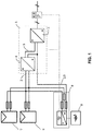
- the system shown in the figure has an inverter 1 with a DC connection 2.
- the inverter has a DC / AC converter 3 and a DC / DC converter 4.
- the inverter has a DC voltage intermediate circuit 5, via which the DC / DC converter and the DC / AC converter are connected.
- the system according to the invention also has two DC power sources 6, 7 in the form of solar modules.
- the DC power sources 6, 7 are connected in parallel.
- the system according to the invention has a further DC source and a DC sink in the form of a battery 8, which can be used in a first operating mode as a DC power source and in a second operating mode as a DC sink.
- the two DC sources 6, 7 and the battery 8 are connected in parallel to the DC terminal 2 of the inverter 1.
- a connection box 9 is provided.
- connection box 9 is in particular the control unit and the DC / DC actuator for carrying out the control method according to the invention.
- the connection box 9 are also the measuring devices for the voltage applied across the DC terminal 2 and the voltage flowing through the DC terminal 2 current. Due to the direct connection of the connection box 9 to the DC connection 2 in parallel connection, the measuring devices integrated in the connection box 9 can perform these measurements. Furthermore, on the output side of the inverter 1, a measuring device for the power output on the output side is provided.
- connection box and thus the battery 8 is connected to the DC voltage intermediate circuit 5.
Landscapes
- Engineering & Computer Science (AREA)
- Power Engineering (AREA)
- Inverter Devices (AREA)
- Charge And Discharge Circuits For Batteries Or The Like (AREA)
- Supply And Distribution Of Alternating Current (AREA)
Claims (10)
- Procédé de commande pour un système, qui présente un onduleur (1) avec alimentation en courant continu (2) et une source de courant électrique continu (6, 7) et une autre source de courant électrique continu et une dépression du courant continu, la source de courant électrique continu (6, 7) et l'autre source de courant électrique continu et la dépression du courant continu étant branchées en parallèle à l'alimentation en courant continu de l'onduleur (1), le système ayant un actionneur avec lequel la puissance fournie par la source de courant électrique continu (6, 7) peut être réglée, et ayant un actionneur avec lequel la tension appliquée à la dépression du courant continu et/ou le courant absorbé par la dépression du courant continu et la puissance absorbée par la dépression du courant continu peuvent être réglées, le système présentant- un dispositif de mesure de la tension, qui peut mesurer la tension à l'alimentation en courant continu, et- une unité d'estimation de la puissance, qui détermine la puissance fournie par l'alimentation en courant continu à l'onduleur (1) ou la puissance fournie par l'alimentation en courant continu de l'onduleur (1), chez lequel l'actionneur, avec lequel la puissance fournie par la source de courant électrique continu (6, 7) peut être réglée, et l'actionneur, avec lequel la tension appliquée à la dépression du courant continu et/ou le courant absorbé par la dépression du courant continu et la puissance absorbée par la dépression du courant continu peuvent être réglés, sont réglés de telle sorte que- la tension à l'alimentation en courant continu (2) et/ou- la tension fournie par l'alimentation en courant continu (2) à l'onduleur (1) ou la tension fournie par l'alimentation en courant continu (2) de l'onduleur (1) correspondent à une valeur prédéterminée.
- Procédé de commande selon la revendication 1, caractérisé en ce que le système présente un dispositif de mesure du courant qui peut mesurer le courant passant par l'alimentation en courant continu.
- Procédé de commande selon la revendication 1 ou 2, caractérisé en ce que l'actionneur, avec lequel la puissance fournie par la source de courant électrique continu (6, 7) peut être réglée, et l'actionneur, avec lequel la tension appliquée à la dépression du courant continu et/ou le courant absorbé par la dépression du courant continu et la puissance absorbée par la dépression du courant continu peuvent être réglées, sont réglés de telle sorte que- la tension à l'alimentation en courant continu (2) et/ou- la tension fournie par l'alimentation en courant continu (2) à l'onduleur (1) ou la tension fournie par l'alimentation en courant continu (2) de l'onduleur (1) correspondent à une valeur prédéterminée pour une période prédéterminée.
- Procédé de commande selon l'une quelconque des revendications 1 à 3, caractérisé en ce que l'onduleur (1) présente une alimentation en courant alternatif et le système présente- un deuxième dispositif de mesure de la tension, qui peut mesurer la tension à l'alimentation en courant alternatif, et/ou- un deuxième dispositif de mesure de la tension, qui peut mesurer le courant qui passe par l'alimentation en courant alternatif, et/ou- une deuxième unité d'estimation de la puissance, qui détermine la puissance fournie par l'alimentation en courant alternatif à l'onduleur (1) ou la puissance fournie par l'alimentation en courant alternatif de l'onduleur (1), chez lequel la valeur prédéterminée est fixée en fonction d'une valeur établie par le deuxième dispositif de mesure de la tension, le deuxième dispositif de mesure du courant et/ou de la deuxième unité d'estimation de la puissance.
- Procédé de commande selon l'une quelconque des revendications 1 à 2, caractérisé en ce que la valeur prédéterminée est à sélectionner de telle sorte que l'onduleur (1) fonctionne à un point de fonctionnement prédéterminé.
- Système qui effectue le procédé de commande selon la revendication 1 et présente un onduleur (1) avec alimentation en courant continu (2) et une source de courant électrique continu (6, 7) et une autre source de courant électrique continu et une dépression de courant continu, la source de courant électrique continu (6, 7) et l'autre source de courant électrique continu et la dépression du courant continu étant branchées en parallèle à l'alimentation en courant continu (2) de l'onduleur (1), le système ayant un actionneur avec lequel la puissance fournie par la source de courant électrique continu (6, 7) peut être réglée, et ayant un actionneur avec lequel la tension appliquée à la dépression du courant continu et/ou le courant absorbé par la dépression du courant continu et la puissance absorbée par la dépression du courant continu peuvent être réglés, le système présentant- un dispositif de mesure de la tension, qui peut mesurer la tension à l'alimentation en courant continu (2) et- une unité d'estimation de la puissance, qui détermine la puissance fournie par l'alimentation en courant continu (2) à l'onduleur (1) ou la puissance fournie par l'alimentation en courant continu (2) de l'onduleur (1).
- Système selon la revendication 6, caractérisé en ce que la source de courant électrique continu (6, 7) est un module photovoltaïque ou une chaîne de modules photovoltaïques ou une éolienne avec redresseur ou une turbine à vapeur avec un générateur branché et un redresseur.
- Système selon la revendication 6 ou 7, caractérisé en ce que le système présente une batterie (8) qui peut être utilisée comme source de courant électrique continu (6, 7) dans un premier mode de fonctionnement et comme dépression de courant continu dans un deuxième mode de fonctionnement.
- Système selon l'une quelconque des revendications 6 à 8, caractérisé en un bus CC qui est branché à l'alimentation en courant continu (2) et auquel la source de courant électrique continu (6, 7) et l'autre source de courant électrique continu ou la dépression de courant continu sont branchées.
- Système selon l'une quelconque des revendications 6 à 9, caractérisé en ce que l'onduleur (1) présente un convertisseur CC/CC (4) branché en aval de l'alimentation en courant continu (2) et un circuit intermédiaire à tension continue (5) auquel sont branchés le convertisseur CC/CC (4) et un convertisseur CC/CA (3), l'autre source de courant électrique continu ou la dépression de courant continu du système pouvant être branchée à l'alimentation en courant continu (2) et au circuit intermédiaire à tension continue (5).
Priority Applications (3)
| Application Number | Priority Date | Filing Date | Title |
|---|---|---|---|
| EP14001342.6A EP2933895B2 (fr) | 2014-04-14 | 2014-04-14 | Procédé de réglage et système doté d'un onduleur, d'une source de courant continu et d'une autre source de courant continu ou d'un écoulement de courant continu |
| US14/676,368 US10243395B2 (en) | 2014-04-14 | 2015-04-01 | Control method and system with an inverter, a direct current source, and an additional direct current source or a direct current sink |
| JP2015082470A JP6710020B2 (ja) | 2014-04-14 | 2015-04-14 | インバータと直流電源と別の直流ソース及び/又は直流シンクを備えたシステムのための制御方法 |
Applications Claiming Priority (1)
| Application Number | Priority Date | Filing Date | Title |
|---|---|---|---|
| EP14001342.6A EP2933895B2 (fr) | 2014-04-14 | 2014-04-14 | Procédé de réglage et système doté d'un onduleur, d'une source de courant continu et d'une autre source de courant continu ou d'un écoulement de courant continu |
Publications (3)
| Publication Number | Publication Date |
|---|---|
| EP2933895A1 EP2933895A1 (fr) | 2015-10-21 |
| EP2933895B1 true EP2933895B1 (fr) | 2018-10-31 |
| EP2933895B2 EP2933895B2 (fr) | 2021-11-03 |
Family
ID=50513639
Family Applications (1)
| Application Number | Title | Priority Date | Filing Date |
|---|---|---|---|
| EP14001342.6A Active EP2933895B2 (fr) | 2014-04-14 | 2014-04-14 | Procédé de réglage et système doté d'un onduleur, d'une source de courant continu et d'une autre source de courant continu ou d'un écoulement de courant continu |
Country Status (3)
| Country | Link |
|---|---|
| US (1) | US10243395B2 (fr) |
| EP (1) | EP2933895B2 (fr) |
| JP (1) | JP6710020B2 (fr) |
Families Citing this family (1)
| Publication number | Priority date | Publication date | Assignee | Title |
|---|---|---|---|---|
| US20170170662A1 (en) * | 2015-12-15 | 2017-06-15 | Marvin S. Keshner | Parallel-Connected Solar Panel Array System with Split Inverter |
Citations (4)
| Publication number | Priority date | Publication date | Assignee | Title |
|---|---|---|---|---|
| US20050225090A1 (en) | 2000-09-07 | 2005-10-13 | Aloys Wobben | Island network and method for operation of an island network |
| DE102010032822A1 (de) | 2010-04-21 | 2011-10-27 | Thomas Fricke | Stromerzeugungssystem und Verfahren zum Betreiben eines solchen |
| DE102012109420A1 (de) | 2011-10-07 | 2013-04-11 | Sma Solar Technology Ag | Wechselrichter, insbesondere Photovoltaikwechselrichter, mit Generatoranschluss und Batterieanschluss |
| WO2013117305A2 (fr) | 2012-02-07 | 2013-08-15 | Sew-Eurodrive Gmbh & Co. Kg | Système de production d'énergie doté d'un accumulateur d'énergie et procédé de fonctionnement d'un système de production d'énergie |
Family Cites Families (10)
| Publication number | Priority date | Publication date | Assignee | Title |
|---|---|---|---|---|
| JPH1031525A (ja) | 1996-07-15 | 1998-02-03 | Fuji Electric Co Ltd | 太陽光発電システム |
| JP5541982B2 (ja) | 2010-06-28 | 2014-07-09 | シャープ株式会社 | 直流配電システム |
| US8970176B2 (en) * | 2010-11-15 | 2015-03-03 | Bloom Energy Corporation | DC micro-grid |
| JP5526043B2 (ja) | 2011-01-06 | 2014-06-18 | シャープ株式会社 | 直流給電システム |
| US8854004B2 (en) | 2011-01-12 | 2014-10-07 | Samsung Sdi Co., Ltd. | Energy storage system and controlling method thereof |
| WO2013002302A1 (fr) | 2011-06-30 | 2013-01-03 | 三洋電機株式会社 | Dispositif de stockage |
| US8720500B2 (en) | 2011-10-11 | 2014-05-13 | GM Global Technology Operations LLC | Electrical architecture for passive controller wake-up during refuel |
| JP5899479B2 (ja) | 2011-12-28 | 2016-04-06 | パナソニックIpマネジメント株式会社 | 電力変換装置 |
| JP6031759B2 (ja) | 2011-12-28 | 2016-11-24 | 株式会社Ihi | 太陽電池発電システム |
| JP2014106935A (ja) | 2012-11-29 | 2014-06-09 | Noritz Corp | 発電システム |
-
2014
- 2014-04-14 EP EP14001342.6A patent/EP2933895B2/fr active Active
-
2015
- 2015-04-01 US US14/676,368 patent/US10243395B2/en active Active
- 2015-04-14 JP JP2015082470A patent/JP6710020B2/ja active Active
Patent Citations (4)
| Publication number | Priority date | Publication date | Assignee | Title |
|---|---|---|---|---|
| US20050225090A1 (en) | 2000-09-07 | 2005-10-13 | Aloys Wobben | Island network and method for operation of an island network |
| DE102010032822A1 (de) | 2010-04-21 | 2011-10-27 | Thomas Fricke | Stromerzeugungssystem und Verfahren zum Betreiben eines solchen |
| DE102012109420A1 (de) | 2011-10-07 | 2013-04-11 | Sma Solar Technology Ag | Wechselrichter, insbesondere Photovoltaikwechselrichter, mit Generatoranschluss und Batterieanschluss |
| WO2013117305A2 (fr) | 2012-02-07 | 2013-08-15 | Sew-Eurodrive Gmbh & Co. Kg | Système de production d'énergie doté d'un accumulateur d'énergie et procédé de fonctionnement d'un système de production d'énergie |
Non-Patent Citations (8)
| Title |
|---|
| B. WICHERT ET AL.: "Application of Intelligent Control Methods to the Management of Modular Hybrid Energy Systems", AUSTRALIAN AND NEW ZEALAND SOLAR ENERGY SOCIETY, pages 1 - 7, XP055629748, ISBN: 095885209X, [retrieved on 19970000] |
| D.GEIBEL ET AL.: "Improvement of Power Quality and Reliability with Multifunctional PV-Inverters in Distributed Energy Systems", INTERNATIONAL CONFERENCE ELECTRICAL POWER QUALITY AND UTILISATION, Lodz, Poland, pages 1 - 6, XP031561590, ISBN: 978-1-4244-5172-2, [retrieved on 20090000] |
| DOMINIK GEIBE ET AL.: "Informations- und kommunikationstechnologien für die energieversorgung von morgen", ELFTES KASSELER SYMPOSIUM ENERGIE-SYSTEMTECHNIK, pages 1 - 226, XP055629759 |
| DOMINIK GEIBEL ET AL.: "Simulation model based control develop-ment of a multifunctional PV-inverter", EUROPEAN CONFERENCE ON POWER ELECTRONICS AND APPLICATIONS, 4 January 2008 (2008-01-04), pages 1 - 10, XP055629849 |
| DOMINIK GEIBEL: "Multifunctional Photovoltaik Inverter System energy management and improvement of Power Quality and Realiability in industrial environments", KONFERENZBEITRAG 2009 IEEE ENERGY CONVERSION CONGRESS AND EXPOSITION, 6 November 2009 (2009-11-06), pages 3881 - 3888, XP055629846 |
| ERNIE PALOMINO ET AL.: "A CONTROL SYSTEM FOR IMPROVED BATTERY UTILIZATION IN A PV-POWERED PEAK SHAVING SYSTEM", KONFERENZBAND DER 25TH IEEE PHOTOVOLTAIC SPECIALISTS CON- FERENCE, 13 May 1996 (1996-05-13), pages 1525 - 1528, XP010208447, ISBN: 0-7803-3166-4, [retrieved on 19960000] |
| J. JAHN ET AL.: "Multifunktionale Photovoltaikstromrichter zur Verbesserung der Netzqualität", SYMPOSIUM PHOTOVOLTAISCHE SOLAR ENERGIE, 2007, XP055629847, ISBN: 978-3-934681-53-8 |
| JÜRGEN REEKERS ET AL.: "Multifunctional photovoltaic inverters systems -energy management and improvement of power quality and reliability in industrial environments", KASSELER SYMPOSIUM ENERGY SYSTEMS TECHNOLOGY 2006, 2006, pages 41 - 51, XP055629784 |
Also Published As
| Publication number | Publication date |
|---|---|
| EP2933895B2 (fr) | 2021-11-03 |
| JP2015204747A (ja) | 2015-11-16 |
| US20150318703A1 (en) | 2015-11-05 |
| EP2933895A1 (fr) | 2015-10-21 |
| JP6710020B2 (ja) | 2020-06-17 |
| US10243395B2 (en) | 2019-03-26 |
Similar Documents
| Publication | Publication Date | Title |
|---|---|---|
| DE102008004675B3 (de) | Steuerbare Umschaltvorrichtung für ein Solarmodul | |
| EP2325993B1 (fr) | Procédé destiné au fonctionnement d'un onduleur et onduleur | |
| DE102014106162A1 (de) | Hochleistungsspannungskompensation | |
| EP3022835B1 (fr) | Onduleur comprenant au moins deux entrées de courant continu, installation photovoltaïque comprenant un tel onduleur et procédé de commande d'un onduleur | |
| DE102017127311A1 (de) | Vorrichtung und Verfahren zur Vormagnetisierung eines Netztransformators in einem Stromrichtersystem | |
| DE112011105662T5 (de) | Gleichstrom-Stromversorgungsnutzungssystem und Gleichstrom-Mikronetz, das dieses verwendet | |
| DE102013114271B4 (de) | Wechselrichter und verfahren zum betrieb eines wechselrichters | |
| DE102010047652A1 (de) | Photovoltaikanlage mit Wechselrichterbetrieb in Abhängigkeit der Netzspannung | |
| DE112013006090T5 (de) | Leistungsübertragungssystem | |
| EP2761716A2 (fr) | Installation photovoltaïque comportant une sécurité contre l'injection dans un réseau électrique public | |
| DE102011052389A1 (de) | Teilleistungs-Mikrowandlerarchitektur | |
| DE112014006170T5 (de) | Leistungserzeugungssystem eines auf erneuerbarer Energie basierenden elektrischen Leistungsgenerators und Gleichstromleistungsquellenkombinierer, der mit einer Rückstromverhinderungsvorrichtung versehen ist, die in der Lage ist, einen Leistungsverlust in dem Leistungserzeugungssystem zu verhindern | |
| EP2933895B1 (fr) | Procédé de réglage et système doté d'un onduleur, d'une source de courant continu et d'une autre source de courant continu ou d'un écoulement de courant continu | |
| WO2015004034A2 (fr) | Ensemble électrique pourvu d'un onduleur et commutateur intermédiaire pour l'ensemble électrique | |
| DE102013112988B4 (de) | Verfahren zum Betreiben eines DC/DC-Wandlers, über den ein Photovoltaikmodul mit anderen, eine andere Kennlinie aufweisenden Photovoltaikmodulen in Reihe geschaltet ist, sowie entsprechender DC/DC-Wandler und Photovoltaikgenerator | |
| WO2017067645A1 (fr) | Actionneur, système muni d'actionneur, unité de fourniture d'énergie pour réseau de bord d'un véhicule, appareil climatiseur, alimentation électrique pour des circuits électroniques, système de fourniture d'énergie d'unités de centre de calcul, appareil de charge de tension continue pour des véhicules électriques | |
| DE102012217554A1 (de) | Schaltung für Photovoltaik-Module und Verfahren zum Betrieb | |
| DE202014010506U1 (de) | Regelverfahren und System mit einem Wechselrichter, einer Gleichstromquelle und einer weiteren Gleihstromquelle oder einer Gleichstromsenke | |
| WO2018233882A1 (fr) | Module photovoltaïque, unité de commande d'un module photovoltaïque et procédé de commande d'un module photovoltaïque | |
| DE102022112903B4 (de) | Verfahren zur erhöhung der lebensdauer von wandlerschaltern sowie system | |
| EP4070444B1 (fr) | Procédé de fonctionnement d'un onduleur et onduleur permettant de mettre en oeuvre ledit procédé | |
| DE102013109958A1 (de) | Photovoltaikanlage und Verfahren zum Bereitstellen von Regelleistung durch eine Photovoltaikanlage | |
| DE102012201623A1 (de) | Schaltungsanordnung mit einem Schaltwandler | |
| DE102012210207A1 (de) | Verfahren und eine Vorrichtung zum Einspeisen von elektrischer Leistung in ein elektrisches Energieversorgungsnetz | |
| DE102011075658A1 (de) | Verfahren zum Erzeugen von Energie mittels einer Photovoltaikanlage und Photovoltaikanlage |
Legal Events
| Date | Code | Title | Description |
|---|---|---|---|
| PUAI | Public reference made under article 153(3) epc to a published international application that has entered the european phase |
Free format text: ORIGINAL CODE: 0009012 |
|
| AK | Designated contracting states |
Kind code of ref document: A1 Designated state(s): AL AT BE BG CH CY CZ DE DK EE ES FI FR GB GR HR HU IE IS IT LI LT LU LV MC MK MT NL NO PL PT RO RS SE SI SK SM TR |
|
| AX | Request for extension of the european patent |
Extension state: BA ME |
|
| RAP1 | Party data changed (applicant data changed or rights of an application transferred) |
Owner name: PRZYBILLA, MANFRED |
|
| RAP1 | Party data changed (applicant data changed or rights of an application transferred) |
Owner name: AMBIBOX GMBH |
|
| RIN1 | Information on inventor provided before grant (corrected) |
Inventor name: PRZYBILLA, MANFRED Inventor name: LEHRMANN, SASCHA Inventor name: FIEBER, KAI |
|
| 17P | Request for examination filed |
Effective date: 20160419 |
|
| RBV | Designated contracting states (corrected) |
Designated state(s): AL AT BE BG CH CY CZ DE DK EE ES FI FR GB GR HR HU IE IS IT LI LT LU LV MC MK MT NL NO PL PT RO RS SE SI SK SM TR |
|
| STAA | Information on the status of an ep patent application or granted ep patent |
Free format text: STATUS: EXAMINATION IS IN PROGRESS |
|
| 17Q | First examination report despatched |
Effective date: 20170419 |
|
| GRAP | Despatch of communication of intention to grant a patent |
Free format text: ORIGINAL CODE: EPIDOSNIGR1 |
|
| STAA | Information on the status of an ep patent application or granted ep patent |
Free format text: STATUS: GRANT OF PATENT IS INTENDED |
|
| INTG | Intention to grant announced |
Effective date: 20180627 |
|
| GRAS | Grant fee paid |
Free format text: ORIGINAL CODE: EPIDOSNIGR3 |
|
| GRAA | (expected) grant |
Free format text: ORIGINAL CODE: 0009210 |
|
| STAA | Information on the status of an ep patent application or granted ep patent |
Free format text: STATUS: THE PATENT HAS BEEN GRANTED |
|
| AK | Designated contracting states |
Kind code of ref document: B1 Designated state(s): AL AT BE BG CH CY CZ DE DK EE ES FI FR GB GR HR HU IE IS IT LI LT LU LV MC MK MT NL NO PL PT RO RS SE SI SK SM TR |
|
| REG | Reference to a national code |
Ref country code: CH Ref legal event code: EP Ref country code: GB Ref legal event code: FG4D Free format text: NOT ENGLISH |
|
| REG | Reference to a national code |
Ref country code: AT Ref legal event code: REF Ref document number: 1060558 Country of ref document: AT Kind code of ref document: T Effective date: 20181115 |
|
| REG | Reference to a national code |
Ref country code: DE Ref legal event code: R096 Ref document number: 502014009895 Country of ref document: DE |
|
| REG | Reference to a national code |
Ref country code: IE Ref legal event code: FG4D Free format text: LANGUAGE OF EP DOCUMENT: GERMAN |
|
| REG | Reference to a national code |
Ref country code: SE Ref legal event code: TRGR |
|
| REG | Reference to a national code |
Ref country code: NL Ref legal event code: MP Effective date: 20181031 |
|
| REG | Reference to a national code |
Ref country code: LT Ref legal event code: MG4D |
|
| PG25 | Lapsed in a contracting state [announced via postgrant information from national office to epo] |
Ref country code: LV Free format text: LAPSE BECAUSE OF FAILURE TO SUBMIT A TRANSLATION OF THE DESCRIPTION OR TO PAY THE FEE WITHIN THE PRESCRIBED TIME-LIMIT Effective date: 20181031 Ref country code: IS Free format text: LAPSE BECAUSE OF FAILURE TO SUBMIT A TRANSLATION OF THE DESCRIPTION OR TO PAY THE FEE WITHIN THE PRESCRIBED TIME-LIMIT Effective date: 20190228 Ref country code: HR Free format text: LAPSE BECAUSE OF FAILURE TO SUBMIT A TRANSLATION OF THE DESCRIPTION OR TO PAY THE FEE WITHIN THE PRESCRIBED TIME-LIMIT Effective date: 20181031 Ref country code: NO Free format text: LAPSE BECAUSE OF FAILURE TO SUBMIT A TRANSLATION OF THE DESCRIPTION OR TO PAY THE FEE WITHIN THE PRESCRIBED TIME-LIMIT Effective date: 20190131 Ref country code: BG Free format text: LAPSE BECAUSE OF FAILURE TO SUBMIT A TRANSLATION OF THE DESCRIPTION OR TO PAY THE FEE WITHIN THE PRESCRIBED TIME-LIMIT Effective date: 20190131 Ref country code: PL Free format text: LAPSE BECAUSE OF FAILURE TO SUBMIT A TRANSLATION OF THE DESCRIPTION OR TO PAY THE FEE WITHIN THE PRESCRIBED TIME-LIMIT Effective date: 20181031 Ref country code: ES Free format text: LAPSE BECAUSE OF FAILURE TO SUBMIT A TRANSLATION OF THE DESCRIPTION OR TO PAY THE FEE WITHIN THE PRESCRIBED TIME-LIMIT Effective date: 20181031 Ref country code: LT Free format text: LAPSE BECAUSE OF FAILURE TO SUBMIT A TRANSLATION OF THE DESCRIPTION OR TO PAY THE FEE WITHIN THE PRESCRIBED TIME-LIMIT Effective date: 20181031 Ref country code: FI Free format text: LAPSE BECAUSE OF FAILURE TO SUBMIT A TRANSLATION OF THE DESCRIPTION OR TO PAY THE FEE WITHIN THE PRESCRIBED TIME-LIMIT Effective date: 20181031 |
|
| PG25 | Lapsed in a contracting state [announced via postgrant information from national office to epo] |
Ref country code: PT Free format text: LAPSE BECAUSE OF FAILURE TO SUBMIT A TRANSLATION OF THE DESCRIPTION OR TO PAY THE FEE WITHIN THE PRESCRIBED TIME-LIMIT Effective date: 20190301 Ref country code: GR Free format text: LAPSE BECAUSE OF FAILURE TO SUBMIT A TRANSLATION OF THE DESCRIPTION OR TO PAY THE FEE WITHIN THE PRESCRIBED TIME-LIMIT Effective date: 20190201 Ref country code: RS Free format text: LAPSE BECAUSE OF FAILURE TO SUBMIT A TRANSLATION OF THE DESCRIPTION OR TO PAY THE FEE WITHIN THE PRESCRIBED TIME-LIMIT Effective date: 20181031 Ref country code: AL Free format text: LAPSE BECAUSE OF FAILURE TO SUBMIT A TRANSLATION OF THE DESCRIPTION OR TO PAY THE FEE WITHIN THE PRESCRIBED TIME-LIMIT Effective date: 20181031 Ref country code: NL Free format text: LAPSE BECAUSE OF FAILURE TO SUBMIT A TRANSLATION OF THE DESCRIPTION OR TO PAY THE FEE WITHIN THE PRESCRIBED TIME-LIMIT Effective date: 20181031 |
|
| PG25 | Lapsed in a contracting state [announced via postgrant information from national office to epo] |
Ref country code: DK Free format text: LAPSE BECAUSE OF FAILURE TO SUBMIT A TRANSLATION OF THE DESCRIPTION OR TO PAY THE FEE WITHIN THE PRESCRIBED TIME-LIMIT Effective date: 20181031 Ref country code: IT Free format text: LAPSE BECAUSE OF FAILURE TO SUBMIT A TRANSLATION OF THE DESCRIPTION OR TO PAY THE FEE WITHIN THE PRESCRIBED TIME-LIMIT Effective date: 20181031 |
|
| REG | Reference to a national code |
Ref country code: DE Ref legal event code: R026 Ref document number: 502014009895 Country of ref document: DE |
|
| PLBI | Opposition filed |
Free format text: ORIGINAL CODE: 0009260 |
|
| PLAX | Notice of opposition and request to file observation + time limit sent |
Free format text: ORIGINAL CODE: EPIDOSNOBS2 |
|
| PG25 | Lapsed in a contracting state [announced via postgrant information from national office to epo] |
Ref country code: RO Free format text: LAPSE BECAUSE OF FAILURE TO SUBMIT A TRANSLATION OF THE DESCRIPTION OR TO PAY THE FEE WITHIN THE PRESCRIBED TIME-LIMIT Effective date: 20181031 Ref country code: SK Free format text: LAPSE BECAUSE OF FAILURE TO SUBMIT A TRANSLATION OF THE DESCRIPTION OR TO PAY THE FEE WITHIN THE PRESCRIBED TIME-LIMIT Effective date: 20181031 Ref country code: EE Free format text: LAPSE BECAUSE OF FAILURE TO SUBMIT A TRANSLATION OF THE DESCRIPTION OR TO PAY THE FEE WITHIN THE PRESCRIBED TIME-LIMIT Effective date: 20181031 Ref country code: SM Free format text: LAPSE BECAUSE OF FAILURE TO SUBMIT A TRANSLATION OF THE DESCRIPTION OR TO PAY THE FEE WITHIN THE PRESCRIBED TIME-LIMIT Effective date: 20181031 |
|
| 26 | Opposition filed |
Opponent name: SMA SOLAR TECHNOLOGY AG Effective date: 20190731 |
|
| PG25 | Lapsed in a contracting state [announced via postgrant information from national office to epo] |
Ref country code: SI Free format text: LAPSE BECAUSE OF FAILURE TO SUBMIT A TRANSLATION OF THE DESCRIPTION OR TO PAY THE FEE WITHIN THE PRESCRIBED TIME-LIMIT Effective date: 20181031 |
|
| REG | Reference to a national code |
Ref country code: CH Ref legal event code: PL |
|
| REG | Reference to a national code |
Ref country code: BE Ref legal event code: MM Effective date: 20190430 |
|
| PG25 | Lapsed in a contracting state [announced via postgrant information from national office to epo] |
Ref country code: LU Free format text: LAPSE BECAUSE OF NON-PAYMENT OF DUE FEES Effective date: 20190414 Ref country code: MC Free format text: LAPSE BECAUSE OF FAILURE TO SUBMIT A TRANSLATION OF THE DESCRIPTION OR TO PAY THE FEE WITHIN THE PRESCRIBED TIME-LIMIT Effective date: 20181031 |
|
| PLBB | Reply of patent proprietor to notice(s) of opposition received |
Free format text: ORIGINAL CODE: EPIDOSNOBS3 |
|
| PG25 | Lapsed in a contracting state [announced via postgrant information from national office to epo] |
Ref country code: LI Free format text: LAPSE BECAUSE OF NON-PAYMENT OF DUE FEES Effective date: 20190430 Ref country code: CH Free format text: LAPSE BECAUSE OF NON-PAYMENT OF DUE FEES Effective date: 20190430 |
|
| PG25 | Lapsed in a contracting state [announced via postgrant information from national office to epo] |
Ref country code: BE Free format text: LAPSE BECAUSE OF NON-PAYMENT OF DUE FEES Effective date: 20190430 |
|
| PG25 | Lapsed in a contracting state [announced via postgrant information from national office to epo] |
Ref country code: TR Free format text: LAPSE BECAUSE OF FAILURE TO SUBMIT A TRANSLATION OF THE DESCRIPTION OR TO PAY THE FEE WITHIN THE PRESCRIBED TIME-LIMIT Effective date: 20181031 |
|
| PG25 | Lapsed in a contracting state [announced via postgrant information from national office to epo] |
Ref country code: IE Free format text: LAPSE BECAUSE OF NON-PAYMENT OF DUE FEES Effective date: 20190414 |
|
| PLBP | Opposition withdrawn |
Free format text: ORIGINAL CODE: 0009264 |
|
| PG25 | Lapsed in a contracting state [announced via postgrant information from national office to epo] |
Ref country code: CY Free format text: LAPSE BECAUSE OF FAILURE TO SUBMIT A TRANSLATION OF THE DESCRIPTION OR TO PAY THE FEE WITHIN THE PRESCRIBED TIME-LIMIT Effective date: 20181031 |
|
| PG25 | Lapsed in a contracting state [announced via postgrant information from national office to epo] |
Ref country code: MT Free format text: LAPSE BECAUSE OF FAILURE TO SUBMIT A TRANSLATION OF THE DESCRIPTION OR TO PAY THE FEE WITHIN THE PRESCRIBED TIME-LIMIT Effective date: 20181031 Ref country code: HU Free format text: LAPSE BECAUSE OF FAILURE TO SUBMIT A TRANSLATION OF THE DESCRIPTION OR TO PAY THE FEE WITHIN THE PRESCRIBED TIME-LIMIT; INVALID AB INITIO Effective date: 20140414 |
|
| PUAH | Patent maintained in amended form |
Free format text: ORIGINAL CODE: 0009272 |
|
| STAA | Information on the status of an ep patent application or granted ep patent |
Free format text: STATUS: PATENT MAINTAINED AS AMENDED |
|
| 27A | Patent maintained in amended form |
Effective date: 20211103 |
|
| AK | Designated contracting states |
Kind code of ref document: B2 Designated state(s): AL AT BE BG CH CY CZ DE DK EE ES FI FR GB GR HR HU IE IS IT LI LT LU LV MC MK MT NL NO PL PT RO RS SE SI SK SM TR |
|
| REG | Reference to a national code |
Ref country code: DE Ref legal event code: R102 Ref document number: 502014009895 Country of ref document: DE |
|
| REG | Reference to a national code |
Ref country code: SE Ref legal event code: RPEO |
|
| PG25 | Lapsed in a contracting state [announced via postgrant information from national office to epo] |
Ref country code: MK Free format text: LAPSE BECAUSE OF FAILURE TO SUBMIT A TRANSLATION OF THE DESCRIPTION OR TO PAY THE FEE WITHIN THE PRESCRIBED TIME-LIMIT Effective date: 20181031 |
|
| P01 | Opt-out of the competence of the unified patent court (upc) registered |
Effective date: 20230513 |
|
| PGFP | Annual fee paid to national office [announced via postgrant information from national office to epo] |
Ref country code: FR Payment date: 20230417 Year of fee payment: 10 Ref country code: DE Payment date: 20230519 Year of fee payment: 10 Ref country code: CZ Payment date: 20230403 Year of fee payment: 10 |
|
| PGFP | Annual fee paid to national office [announced via postgrant information from national office to epo] |
Ref country code: SE Payment date: 20230419 Year of fee payment: 10 Ref country code: AT Payment date: 20230414 Year of fee payment: 10 |
|
| PGFP | Annual fee paid to national office [announced via postgrant information from national office to epo] |
Ref country code: GB Payment date: 20230420 Year of fee payment: 10 |