EP2933883B1 - Instabile laserresonanzkavität mit passivem auslöser, der mit sättigungsfähigem absorptionsmaterial mit absorptionsgefälle ausgestattet ist - Google Patents
Instabile laserresonanzkavität mit passivem auslöser, der mit sättigungsfähigem absorptionsmaterial mit absorptionsgefälle ausgestattet ist Download PDFInfo
- Publication number
- EP2933883B1 EP2933883B1 EP15160392.5A EP15160392A EP2933883B1 EP 2933883 B1 EP2933883 B1 EP 2933883B1 EP 15160392 A EP15160392 A EP 15160392A EP 2933883 B1 EP2933883 B1 EP 2933883B1
- Authority
- EP
- European Patent Office
- Prior art keywords
- laser cavity
- absorption
- laser
- passive
- gradient
- Prior art date
- Legal status (The legal status is an assumption and is not a legal conclusion. Google has not performed a legal analysis and makes no representation as to the accuracy of the status listed.)
- Active
Links
Images

Classifications
-
- H—ELECTRICITY
- H01—ELECTRIC ELEMENTS
- H01S—DEVICES USING THE PROCESS OF LIGHT AMPLIFICATION BY STIMULATED EMISSION OF RADIATION [LASER] TO AMPLIFY OR GENERATE LIGHT; DEVICES USING STIMULATED EMISSION OF ELECTROMAGNETIC RADIATION IN WAVE RANGES OTHER THAN OPTICAL
- H01S3/00—Lasers, i.e. devices using stimulated emission of electromagnetic radiation in the infrared, visible or ultraviolet wave range
- H01S3/14—Lasers, i.e. devices using stimulated emission of electromagnetic radiation in the infrared, visible or ultraviolet wave range characterised by the material used as the active medium
- H01S3/16—Solid materials
- H01S3/163—Solid materials characterised by a crystal matrix
- H01S3/164—Solid materials characterised by a crystal matrix garnet
- H01S3/1643—YAG
-
- H—ELECTRICITY
- H01—ELECTRIC ELEMENTS
- H01S—DEVICES USING THE PROCESS OF LIGHT AMPLIFICATION BY STIMULATED EMISSION OF RADIATION [LASER] TO AMPLIFY OR GENERATE LIGHT; DEVICES USING STIMULATED EMISSION OF ELECTROMAGNETIC RADIATION IN WAVE RANGES OTHER THAN OPTICAL
- H01S3/00—Lasers, i.e. devices using stimulated emission of electromagnetic radiation in the infrared, visible or ultraviolet wave range
- H01S3/05—Construction or shape of optical resonators; Accommodation of active medium therein; Shape of active medium
- H01S3/06—Construction or shape of active medium
- H01S3/0602—Crystal lasers or glass lasers
- H01S3/0612—Non-homogeneous structure
-
- H—ELECTRICITY
- H01—ELECTRIC ELEMENTS
- H01S—DEVICES USING THE PROCESS OF LIGHT AMPLIFICATION BY STIMULATED EMISSION OF RADIATION [LASER] TO AMPLIFY OR GENERATE LIGHT; DEVICES USING STIMULATED EMISSION OF ELECTROMAGNETIC RADIATION IN WAVE RANGES OTHER THAN OPTICAL
- H01S3/00—Lasers, i.e. devices using stimulated emission of electromagnetic radiation in the infrared, visible or ultraviolet wave range
- H01S3/05—Construction or shape of optical resonators; Accommodation of active medium therein; Shape of active medium
- H01S3/06—Construction or shape of active medium
- H01S3/0602—Crystal lasers or glass lasers
- H01S3/0617—Crystal lasers or glass lasers having a varying composition or cross-section in a specific direction
-
- H—ELECTRICITY
- H01—ELECTRIC ELEMENTS
- H01S—DEVICES USING THE PROCESS OF LIGHT AMPLIFICATION BY STIMULATED EMISSION OF RADIATION [LASER] TO AMPLIFY OR GENERATE LIGHT; DEVICES USING STIMULATED EMISSION OF ELECTROMAGNETIC RADIATION IN WAVE RANGES OTHER THAN OPTICAL
- H01S3/00—Lasers, i.e. devices using stimulated emission of electromagnetic radiation in the infrared, visible or ultraviolet wave range
- H01S3/05—Construction or shape of optical resonators; Accommodation of active medium therein; Shape of active medium
- H01S3/08—Construction or shape of optical resonators or components thereof
- H01S3/08059—Constructional details of the reflector, e.g. shape
- H01S3/08063—Graded reflectivity, e.g. variable reflectivity mirror
-
- H—ELECTRICITY
- H01—ELECTRIC ELEMENTS
- H01S—DEVICES USING THE PROCESS OF LIGHT AMPLIFICATION BY STIMULATED EMISSION OF RADIATION [LASER] TO AMPLIFY OR GENERATE LIGHT; DEVICES USING STIMULATED EMISSION OF ELECTROMAGNETIC RADIATION IN WAVE RANGES OTHER THAN OPTICAL
- H01S3/00—Lasers, i.e. devices using stimulated emission of electromagnetic radiation in the infrared, visible or ultraviolet wave range
- H01S3/05—Construction or shape of optical resonators; Accommodation of active medium therein; Shape of active medium
- H01S3/08—Construction or shape of optical resonators or components thereof
- H01S3/08081—Unstable resonators
-
- H—ELECTRICITY
- H01—ELECTRIC ELEMENTS
- H01S—DEVICES USING THE PROCESS OF LIGHT AMPLIFICATION BY STIMULATED EMISSION OF RADIATION [LASER] TO AMPLIFY OR GENERATE LIGHT; DEVICES USING STIMULATED EMISSION OF ELECTROMAGNETIC RADIATION IN WAVE RANGES OTHER THAN OPTICAL
- H01S3/00—Lasers, i.e. devices using stimulated emission of electromagnetic radiation in the infrared, visible or ultraviolet wave range
- H01S3/09—Processes or apparatus for excitation, e.g. pumping
- H01S3/091—Processes or apparatus for excitation, e.g. pumping using optical pumping
- H01S3/094—Processes or apparatus for excitation, e.g. pumping using optical pumping by coherent light
- H01S3/0941—Processes or apparatus for excitation, e.g. pumping using optical pumping by coherent light of a laser diode
-
- H—ELECTRICITY
- H01—ELECTRIC ELEMENTS
- H01S—DEVICES USING THE PROCESS OF LIGHT AMPLIFICATION BY STIMULATED EMISSION OF RADIATION [LASER] TO AMPLIFY OR GENERATE LIGHT; DEVICES USING STIMULATED EMISSION OF ELECTROMAGNETIC RADIATION IN WAVE RANGES OTHER THAN OPTICAL
- H01S3/00—Lasers, i.e. devices using stimulated emission of electromagnetic radiation in the infrared, visible or ultraviolet wave range
- H01S3/10—Controlling the intensity, frequency, phase, polarisation or direction of the emitted radiation, e.g. switching, gating, modulating or demodulating
- H01S3/11—Mode locking; Q-switching; Other giant-pulse techniques, e.g. cavity dumping
- H01S3/1123—Q-switching
- H01S3/113—Q-switching using intracavity saturable absorbers
-
- H—ELECTRICITY
- H01—ELECTRIC ELEMENTS
- H01S—DEVICES USING THE PROCESS OF LIGHT AMPLIFICATION BY STIMULATED EMISSION OF RADIATION [LASER] TO AMPLIFY OR GENERATE LIGHT; DEVICES USING STIMULATED EMISSION OF ELECTROMAGNETIC RADIATION IN WAVE RANGES OTHER THAN OPTICAL
- H01S3/00—Lasers, i.e. devices using stimulated emission of electromagnetic radiation in the infrared, visible or ultraviolet wave range
- H01S3/14—Lasers, i.e. devices using stimulated emission of electromagnetic radiation in the infrared, visible or ultraviolet wave range characterised by the material used as the active medium
- H01S3/16—Solid materials
- H01S3/1601—Solid materials characterised by an active (lasing) ion
- H01S3/1603—Solid materials characterised by an active (lasing) ion rare earth
- H01S3/1611—Solid materials characterised by an active (lasing) ion rare earth neodymium
-
- H—ELECTRICITY
- H01—ELECTRIC ELEMENTS
- H01S—DEVICES USING THE PROCESS OF LIGHT AMPLIFICATION BY STIMULATED EMISSION OF RADIATION [LASER] TO AMPLIFY OR GENERATE LIGHT; DEVICES USING STIMULATED EMISSION OF ELECTROMAGNETIC RADIATION IN WAVE RANGES OTHER THAN OPTICAL
- H01S3/00—Lasers, i.e. devices using stimulated emission of electromagnetic radiation in the infrared, visible or ultraviolet wave range
- H01S3/14—Lasers, i.e. devices using stimulated emission of electromagnetic radiation in the infrared, visible or ultraviolet wave range characterised by the material used as the active medium
- H01S3/16—Solid materials
- H01S3/1601—Solid materials characterised by an active (lasing) ion
- H01S3/162—Solid materials characterised by an active (lasing) ion transition metal
- H01S3/1623—Solid materials characterised by an active (lasing) ion transition metal chromium, e.g. Alexandrite
-
- H—ELECTRICITY
- H01—ELECTRIC ELEMENTS
- H01S—DEVICES USING THE PROCESS OF LIGHT AMPLIFICATION BY STIMULATED EMISSION OF RADIATION [LASER] TO AMPLIFY OR GENERATE LIGHT; DEVICES USING STIMULATED EMISSION OF ELECTROMAGNETIC RADIATION IN WAVE RANGES OTHER THAN OPTICAL
- H01S5/00—Semiconductor lasers
- H01S5/40—Arrangement of two or more semiconductor lasers, not provided for in groups H01S5/02 - H01S5/30
- H01S5/4025—Array arrangements, e.g. constituted by discrete laser diodes or laser bar
-
- H—ELECTRICITY
- H01—ELECTRIC ELEMENTS
- H01S—DEVICES USING THE PROCESS OF LIGHT AMPLIFICATION BY STIMULATED EMISSION OF RADIATION [LASER] TO AMPLIFY OR GENERATE LIGHT; DEVICES USING STIMULATED EMISSION OF ELECTROMAGNETIC RADIATION IN WAVE RANGES OTHER THAN OPTICAL
- H01S3/00—Lasers, i.e. devices using stimulated emission of electromagnetic radiation in the infrared, visible or ultraviolet wave range
- H01S3/05—Construction or shape of optical resonators; Accommodation of active medium therein; Shape of active medium
- H01S3/08—Construction or shape of optical resonators or components thereof
- H01S3/081—Construction or shape of optical resonators or components thereof comprising three or more reflectors
- H01S3/0818—Unstable resonators
Definitions
- the present invention relates to an unstable laser cavity with a passive trigger, and a laser source provided with such a laser cavity.
- lasers provided with laser cavities operating in triggered mode are capable of delivering short light pulses, generally in the range of one to a few tens of nanoseconds, and of high peak power, currently greater than one megawatt.
- the applications of this type of lasers are multiple, both in the civil field (scientific lasers (pumping tunable lasers for example), engraving, marking, ...) and in the military field (designation, telemetry, etc.). ).
- these lasers are triggered, either actively by an electro-optical or acousto-optic device (active trigger), or passively by a saturable absorption component (passive trigger).
- Active triggers have several advantages over passive triggers: control of the trigger time (better than the nanosecond), low temporal jitter, and higher extraction efficiency. On the other hand, these active triggers require electronics that, without being sophisticated, add complexity, bulk, weight, and cost to the trigger.
- the present invention relates to an unstable laser cavity that overcomes these disadvantages, and which is defined by the technical features disclosed by claim 1.
- the unstable laser cavity provided with a passive trigger is remarkable in that the passive trigger comprises a saturable absorber which has an absorption gradient, that is to say whose profile absorption is inhomogeneous on the beam section flowing in the laser cavity.
- an absorption profile can be provided which is such that the residual absorption is almost nil on a part of section where the Most of the energy is extracted, i.e. generally at the edges of the pumped active element.
- the combination of an unstable cavity, the energy extraction of which is generally carried out by diffraction on the periphery of a coupling mirror, with such a passive saturable absorber with absorption gradient (for which a residual absorption is almost zero) leads to a yield close to that provided by an unstable cavity comprising an active trigger, without presenting the disadvantages of such an active trigger: complexity, size, weight and cost.
- a laser cavity is thus available making it possible to obtain an extraction efficiency similar to that achieved with an active trigger.
- the passive trigger is integrated in an active medium, in particular a laser bar, of the laser cavity.
- said active medium is of the ceramic type and comprises a part constituting the passive trigger, and in a second variant embodiment, the active medium comprises, in addition to a main doping intended for a laser emission. , a secondary doping having a doping gradient and making it possible to create the passive trigger.
- the passive release is arranged at a downstream longitudinal end of the active medium or longitudinally in the elongated active medium (while being centered on the longitudinal axis of the active medium).
- said laser source comprises at least one unstable laser cavity provided with a passive trigger (with saturable absorber having an absorption gradient) as described in claim 1.
- This laser cavity 1 is of unstable type. Usually, in an unstable laser cavity, a light beam 17 flowing in the cavity, moves away from the optical axis (axis XX) as and when it is propagated, as shown in FIG. figure 1 . A portion of the beam 17 flowing in the cavity 1, generally the radially outer portion relative to the optical axis XX is transmitted out of the cavity 1 by an optical element (mirror 3) provided for this purpose to form the extracted or useful laser beam 7.
- an optical element mirror 3
- the laser cavity 1 (or optical cavity) shown schematically on the figure 1 , is intended to be used in a laser source 8.
- the laser cavity 1 gives the laser beam 7 which is extracted in the manner specified below, its directivity characteristics (arrow E) and geometry.
- said unstable type laser cavity 1 operates in a tripped mode and is provided for this purpose with a passive trigger 10.
- the passive trigger 10 comprises a saturable absorber 11 which has an absorption gradient.
- the saturable absorber 11 of the passive release 10 has nonhomogeneous absorption characteristics, that is to say comprising an absorption profile which is inhomogeneous, and this on the section (transverse to the axis XX ) of the beam circulating in the laser cavity 1. The absorption therefore varies according to the location on the section.
- the saturable absorber 11 has a radial absorption gradient, with greater absorption at the center (at the axis XX) than at the radial ends.
- the radial adjective is defined with respect to the X-X axis transversely thereto.
- a saturable absorber is an absorbent, whose absorption coefficient can vary reversibly under the effect of a sufficiently intense light flux of determined frequency.
- the operation of a saturable absorber is based on the nonlinear optical effect of optically induced transparency: an opaque medium in the initial state becomes transparent when the radiation to which it is subjected becomes sufficiently intense.
- the material used for the saturable absorber 11 must have an absorption at the wavelength emitted by the laser source, and the absorption coefficient at this wavelength must decrease under effect of sufficiently intense radiation at this wavelength.
- the unstable laser cavity 1 is confocal with a positive branch with a coupling mirror 3 of supergaussian type (that is to say which has a variable reflectivity whose reflectivity curve is super-Gaussian), so that the laser beam 7 of output is collimated.
- the passive absorption gradient trigger 10 is placed just before the coupling mirror 3 in the direction E (defined by the direction of extraction of the laser beam 7) and its absorption maximum is centered on the axis XX of the laser cavity 1.
- an absorption profile is provided which is such that the residual absorption is almost zero on a part of section where the essential energy is extracted, that is to say generally on the edges of the coupling mirror 3.
- the combination of an unstable laser cavity 1, the extraction of energy is generally performed by diffraction on the periphery of the coupling mirror 3, with a such a passive 10 saturable absorber with absorption gradient (for which the residual absorption is almost zero), leads to a yield close to that provided by an unstable cavity 1 with an active trigger, without presenting the disadvantages of such an active trigger.
- the extraction of energy stored in the entire volume pumped is performed with optimal performance while ensuring excellent discrimination of the fundamental mode compared to modes of higher order.
- the saturable absorber 11 of said passive trigger 10 is doped inhomogeneously, that is to say with a variable doping concentration.
- the passive trigger 10 is doped according to a doping gradient making it possible to create the absorption gradient, preferably with decreasing radial doping of the center (at the level of the X-X axis) towards the radial ends.
- the saturable absorber (homogeneously doped) has an absorption variation which is generated by a radial variation in its thickness.
- the saturable absorber is thus physically equivalent to a convergent plano-convex lens 12, as shown in FIG. figure 2 . So that this lens 12 has no noticeable effect on the stability of the laser cavity 1, it is embedded in a medium 13 of the same index to form a blade 14 with parallel faces.
- Such a configuration makes it possible to control several sizing parameters, such as, for example, the size of the absorbing lens and the influence of its shape.
- different elements shown schematically on the Figures 3A to 3D .
- the absorbing lens (or pad) 12 does not occupy the entire aperture. It is expected that its shape is reduced to a spherical cap 15 (no extra thickness under the flat surface of the lens). The absorption therefore falls to zero at the periphery 16 of the lens 12.
- the aperture diameter of the beam is ⁇ and the radius of the lens 12 is r 0 .
- T fs 0 is the transmission at the center of the lens 12 for a very low light intensity (low signal transmission).
- the low signal radial transmission is calculated.
- T i r exp Ln T fs r / 1 + I / I sat wherein I sat is the saturation intensity of the saturable absorber.
- a saturable absorber has a saturation transmission that is never equal to 1.
- n g is the population density on the ground state (concentration of doping ions)
- ⁇ ex is the absorption cross section towards the excited states and e the thickness crossed.
- the size of the reflective spot ⁇ m on the mirror 3 depends on the size of the beam that develops in the cavity 1. It is a question of finding a balance between the diffraction losses imposed by the diaphragmation of the beam by the bar 4 and the extraction of energy at the periphery of the coupling mirror 3. Generally, the intensity at the edge of the bar 4 is chosen between 0.2% and 13% of the intensity in the center. In a somewhat arbitrary way, and this can be optimized, we choose to locate the intensity at the edge of the bar 4 at 5% of the intensity in the center.
- the saturable absorber 11 used in the passive release 10 may be Cr 4+ : YAG.
- the energy deposition of pump diodes (of the pumping system 6) is assumed to be uniform throughout the active medium 4 and is realized with efficiency 75% optics. It has a pumping power of 5000 watts at the output of the laser diodes.
- the fluorescence quantum yield of retained Nd: YAG is 92% and the stimulated emission cross section of 2.7 ⁇ 10 -19 cm 2 .
- the embodiment shown diagrammatically in FIG. 9A consists of producing a plano-convex lens 12 of small radius of curvature of absorbent material whose thickness is adjusted to obtain the desired transmission T 0 .
- the complementary part 13 (exactly) is machined in a substrate of the same nature (non-absorbing medium of the same index) to eliminate the effects of convergence. of the lens 12.
- the set of two components 12 and 13 is therefore zero vergence.
- FIG. 9B The embodiment shown diagrammatically in FIG. 9B consists of integrating a cylindrical central portion 17 of homogeneous doping into the blade 1.
- the embodiment shown schematically in Fig. 9C corresponds to the preferred mode.
- the saturable absorber 11 of the passive release is doped according to a doping gradient that makes it possible to create the absorption gradient, in this case a radial absorption gradient, preferably with a greater absorption at the center (at the level of the axis XX) than at the radial ends.
- This embodiment has many advantages.
- the radial absorption gradient has no discontinuity and the flow resistance of the blade 14 is as good as that of a homogeneous blade. A very slight potential residual lens due to the low index gradient can be compensated if necessary by appropriate polishing of one of the faces. Several methods of manufacturing such a blade 14 can be envisaged.
- a doped crystalline matrix such as Cr 4+ : YAG
- the realization of the doping gradient is conceivable if the material is obtained in the form of ceramic.
- a longitudinal doping gradient is feasible by zone heating.
- the structuring of the blade 14 can be performed by selective irradiation of the center.
- the absorption by the colored centers is generally quite low, the crystal is long, typically more than 20 mm.
- the bar 4 is made of ceramic, the saturable saturable absorber function can be integrated into the active medium 4 itself. A self-triggering active medium 4 is then obtained.
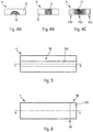
- the passive trigger 10 is therefore directly integrated into the active medium 4 of the laser cavity 1, as shown in FIGS. Figures 5 and 6 .
- said active medium 4 is of ceramic type and comprises a part 10A, 10B constituting the trigger 10.
- the active medium 4 comprises, in addition to a conventional main doping for laser emission, a secondary doping having a doping gradient and for creating the passive trigger.
Landscapes
- Physics & Mathematics (AREA)
- Electromagnetism (AREA)
- Optics & Photonics (AREA)
- Engineering & Computer Science (AREA)
- Plasma & Fusion (AREA)
- Chemical & Material Sciences (AREA)
- Crystallography & Structural Chemistry (AREA)
- Condensed Matter Physics & Semiconductors (AREA)
- General Physics & Mathematics (AREA)
- Inorganic Chemistry (AREA)
- Lasers (AREA)
Claims (8)
- Instabile Laserresonanzkavität, die mit einem passiven Auslöser ausgestattet ist, wobei der passive Auslöser (10) ein sättigungsfähiges Absorptionsmaterial (11) umfasst, das ein Absorptionsgefälle aufweist, sodass das Absorptionsprofil des sättigungsfähigen Absorptionsmaterials (11) auf dem Strahlabschnitt (17), der in der Laserresonanzkavität (1) zirkuliert, inhomogen ist, wobei die instabile Laserresonanzkavität dadurch gekennzeichnet ist, dass der passive Auslöser (10) gemäß einem Dotierungsgefälle dotiert ist, wodurch die Erzeugung eines radialen Absorptionsgefälles ermöglicht wird, wobei das radiale Absorptionsgefälle im Zentrum eine höhere Absorption aufweist als an den radialen Enden und die Absorption an den Rändern quasi Null ist.
- Laserresonanzkavität nach Anspruch 1, umfassend mindestens ein aktives Medium (4),
dadurch gekennzeichnet, dass der passive Auslöser in dem aktiven Medium (4) der Laserresonanzkavität (1) integriert ist. - Laserresonanzkavität nach Anspruch 2,
dadurch gekennzeichnet, dass das aktive Medium (4) keramischer Art ist und ein Teil (10A, 10B) beinhaltet, das den Auslöser (10) bildet. - Laserresonanzkavität nach Anspruch 2,
dadurch gekennzeichnet, dass das aktive Medium (4) zusätzlich zu einer Hauptdotierung, die zu einer Laseremission bestimmt ist, eine Sekundärdotierung umfasst, die das Dotierungsgefälle aufweist und die Erzeugung des passiven Auslösers ermöglicht. - Laserresonanzkavität nach einem der Ansprüche 2 bis 4, dadurch gekennzeichnet, dass der passive Auslöser (10) an einem stromabwärts liegenden Längsende (4A) des aktiven Mediums (4) angeordnet ist.
- Laserresonanzkavität nach einem der Ansprüche 2 bis 4, dadurch gekennzeichnet, dass der passive Auslöser (10) längs im länglichen aktiven Medium (4) angeordnet ist, wobei er auf der Längsachse (X-X) des aktiven Mediums (4) zentriert ist.
- Laserresonanzkavität nach einem der vorstehenden Ansprüche,
dadurch gekennzeichnet, dass sie konfokaler Art ist. - Laserquelle, mindestens beinhaltend:- eine Laserresonanzkavität (1), umfassend mindestens ein aktives Medium (4);- ein Pumpsystem (6) zum Aussenden mindestens eines Pumpstrahls (5); und- ein optisches Transportsystem, um den Pumpstrahl (5) zum aktiven Medium (4) der Laserresonanzkavität (1) zu leiten,dadurch gekennzeichnet, dass die Laserresonanzkavität (1) so ist wie jene nach einem der Ansprüche 1 bis 7.
Applications Claiming Priority (1)
| Application Number | Priority Date | Filing Date | Title |
|---|---|---|---|
| FR1400744A FR3019388B1 (fr) | 2014-03-27 | 2014-03-27 | Cavite laser instable a declencheur passif pourvu d'un absorbant saturable a gradient d'absorption |
Publications (2)
| Publication Number | Publication Date |
|---|---|
| EP2933883A1 EP2933883A1 (de) | 2015-10-21 |
| EP2933883B1 true EP2933883B1 (de) | 2018-10-10 |
Family
ID=51260915
Family Applications (1)
| Application Number | Title | Priority Date | Filing Date |
|---|---|---|---|
| EP15160392.5A Active EP2933883B1 (de) | 2014-03-27 | 2015-03-23 | Instabile laserresonanzkavität mit passivem auslöser, der mit sättigungsfähigem absorptionsmaterial mit absorptionsgefälle ausgestattet ist |
Country Status (3)
| Country | Link |
|---|---|
| US (1) | US9819140B2 (de) |
| EP (1) | EP2933883B1 (de) |
| FR (1) | FR3019388B1 (de) |
Families Citing this family (5)
| Publication number | Priority date | Publication date | Assignee | Title |
|---|---|---|---|---|
| CN107221830B (zh) * | 2017-07-27 | 2019-02-22 | 中国科学院长春光学精密机械与物理研究所 | 一种非稳腔单频激光输出装置 |
| CN112771735B (zh) * | 2018-09-14 | 2024-10-15 | 大学共同利用机关法人自然科学研究机构 | 光振荡器 |
| CN113056682B (zh) * | 2019-10-24 | 2022-04-29 | 趣眼有限公司 | 光子系统及方法 |
| DE102019135176A1 (de) * | 2019-12-19 | 2021-06-24 | Hauni Maschinenbau Gmbh | Modulares Verdampfersystem zum Verdampfen einer Zusammensetzung |
| WO2022053924A1 (en) * | 2020-09-08 | 2022-03-17 | Trieye Ltd. | Novel passively q‑switched laser |
Family Cites Families (11)
| Publication number | Priority date | Publication date | Assignee | Title |
|---|---|---|---|---|
| CA1164990A (en) * | 1982-01-18 | 1984-04-03 | United States (Government Of The) As Represented By The Secretary Of The Army | Hybrid unstable resonator laser cartridge |
| US5390211A (en) * | 1993-08-24 | 1995-02-14 | Spectra-Physics Lasers, Inc. | Optical parametric oscillator with unstable resonator |
| US5388114A (en) * | 1994-03-17 | 1995-02-07 | Polaroid Corporation | Miniaturized self-Q-switched frequency-doubled laser |
| US7568365B2 (en) * | 2001-05-04 | 2009-08-04 | President & Fellows Of Harvard College | Method and apparatus for micromachining bulk transparent materials using localized heating by nonlinearly absorbed laser radiation, and devices fabricated thereby |
| US7065121B2 (en) * | 2001-07-24 | 2006-06-20 | Gsi Group Ltd. | Waveguide architecture, waveguide devices for laser processing and beam control, and laser processing applications |
| US20040119552A1 (en) * | 2002-12-20 | 2004-06-24 | Com Dev Ltd. | Electromagnetic termination with a ferrite absorber |
| US7046712B2 (en) * | 2003-05-02 | 2006-05-16 | Jds Uniphase Corporation | Laser resistant to internal ir-induced damage |
| JP4530348B2 (ja) * | 2004-09-06 | 2010-08-25 | 大学共同利用機関法人自然科学研究機構 | 受動qスイッチレーザ装置 |
| AT502565B1 (de) * | 2005-09-22 | 2008-05-15 | Ge Jenbacher Gmbh & Co Ohg | Verbrennungsmotor mit einer laserlichterzeugungsvorrichtung |
| FR2916310B1 (fr) * | 2007-05-14 | 2009-08-28 | Centre Nat Rech Scient | Laser a puce pulse |
| CN101562310B (zh) * | 2009-05-04 | 2010-09-01 | 北京国科世纪激光技术有限公司 | 被动锁模皮秒激光器 |
-
2014
- 2014-03-27 FR FR1400744A patent/FR3019388B1/fr not_active Expired - Fee Related
-
2015
- 2015-03-23 EP EP15160392.5A patent/EP2933883B1/de active Active
- 2015-03-27 US US14/671,837 patent/US9819140B2/en active Active
Non-Patent Citations (1)
| Title |
|---|
| None * |
Also Published As
| Publication number | Publication date |
|---|---|
| FR3019388B1 (fr) | 2017-06-16 |
| EP2933883A1 (de) | 2015-10-21 |
| FR3019388A1 (fr) | 2015-10-02 |
| US9819140B2 (en) | 2017-11-14 |
| US20150280392A1 (en) | 2015-10-01 |
Similar Documents
| Publication | Publication Date | Title |
|---|---|---|
| EP2933883B1 (de) | Instabile laserresonanzkavität mit passivem auslöser, der mit sättigungsfähigem absorptionsmaterial mit absorptionsgefälle ausgestattet ist | |
| EP2158651B1 (de) | Quelle für ultrakurzen hochleistungslichtimpuls | |
| EP0724315B1 (de) | Mikorlaserkavität und ihr Herstellungsverfahren | |
| EP2147487B1 (de) | Gepulster microchip-laser | |
| EP1849029B2 (de) | Optische verbundfaser für einen laser- und pump-wellen-confinement-laser und verwendung dafür in lasern | |
| EP2018687B1 (de) | Gepulste faseroptische laservorrichtung mit hoher ausgangsleistung | |
| EP2041848B1 (de) | Glasfaserstrom-lasergerät | |
| EP2695253B1 (de) | Optischer faserlaser | |
| EP1115186A1 (de) | Aktives Element für eine Laser-Quelle und Anwendung in einer Laser-Quelle | |
| EP1717914B1 (de) | Aktives Element für Laser-Quelle und Laser-Quelle mit diesem aktiven Element | |
| EP1878096A1 (de) | Durch photonische faser getriggerte lasereinrichtung | |
| EP2676338B1 (de) | Hochleistungs-glasfaserlaser | |
| FR2919123A1 (fr) | Laser a capacite calorifique et milieu laser associe | |
| EP1212814B1 (de) | Gepumpter laser und optimiertes lasermedium | |
| EP2596555A1 (de) | Vorrichtung zur verstärkung eines laserstrahls mit unterdrückung von transversallasern | |
| EP3286811B1 (de) | Optische monomodusfaser zur kompensation einer brechungsindexvariation im zusammenhang mit thermischen effekten und laser mit solch einer optischen faser als verstärkungsmedium | |
| EP3005498B1 (de) | Laserverstärkungssystem für dicke platten und verwendungen davon | |
| EP1966856B1 (de) | Einrichtung mit optischer führung zum erzeugen eines optischen signals durch optisches pumpen und anwendungen der einrichtung | |
| FR2885267A1 (fr) | Element actif pour source laser et source laser comportant un tel element actif. | |
| WO2007026084A1 (fr) | Dispositif de pompage optique | |
| FR2858475A1 (fr) | Source laser de puissance a grande finesse spectrale | |
| FR2858476A1 (fr) | Source laser de puissance a cavite optique en anneau a grande finesse spectrale | |
| WO2016134993A1 (fr) | Dispositif d'absorption de faisceaux parasites transverses dans un amplificateur optique solide, et dispositif d'amplification optique correspondant | |
| FR3018144A1 (fr) | Dispositif d'amplification optique hybride |
Legal Events
| Date | Code | Title | Description |
|---|---|---|---|
| PUAI | Public reference made under article 153(3) epc to a published international application that has entered the european phase |
Free format text: ORIGINAL CODE: 0009012 |
|
| AK | Designated contracting states |
Kind code of ref document: A1 Designated state(s): AL AT BE BG CH CY CZ DE DK EE ES FI FR GB GR HR HU IE IS IT LI LT LU LV MC MK MT NL NO PL PT RO RS SE SI SK SM TR |
|
| AX | Request for extension of the european patent |
Extension state: BA ME |
|
| 17P | Request for examination filed |
Effective date: 20160401 |
|
| RBV | Designated contracting states (corrected) |
Designated state(s): AL AT BE BG CH CY CZ DE DK EE ES FI FR GB GR HR HU IE IS IT LI LT LU LV MC MK MT NL NO PL PT RO RS SE SI SK SM TR |
|
| REG | Reference to a national code |
Ref country code: DE Ref legal event code: R079 Ref document number: 602015017704 Country of ref document: DE Free format text: PREVIOUS MAIN CLASS: H01S0003081000 Ipc: H01S0003094100 |
|
| GRAP | Despatch of communication of intention to grant a patent |
Free format text: ORIGINAL CODE: EPIDOSNIGR1 |
|
| STAA | Information on the status of an ep patent application or granted ep patent |
Free format text: STATUS: GRANT OF PATENT IS INTENDED |
|
| RIC1 | Information provided on ipc code assigned before grant |
Ipc: H01S 3/0941 20060101AFI20180601BHEP Ipc: H01S 3/06 20060101ALI20180601BHEP Ipc: H01S 3/113 20060101ALI20180601BHEP Ipc: H01S 3/08 20060101ALI20180601BHEP Ipc: H01S 3/16 20060101ALI20180601BHEP Ipc: H01S 5/40 20060101ALI20180601BHEP Ipc: H01S 3/081 20060101ALI20180601BHEP |
|
| INTG | Intention to grant announced |
Effective date: 20180620 |
|
| GRAS | Grant fee paid |
Free format text: ORIGINAL CODE: EPIDOSNIGR3 |
|
| GRAA | (expected) grant |
Free format text: ORIGINAL CODE: 0009210 |
|
| STAA | Information on the status of an ep patent application or granted ep patent |
Free format text: STATUS: THE PATENT HAS BEEN GRANTED |
|
| AK | Designated contracting states |
Kind code of ref document: B1 Designated state(s): AL AT BE BG CH CY CZ DE DK EE ES FI FR GB GR HR HU IE IS IT LI LT LU LV MC MK MT NL NO PL PT RO RS SE SI SK SM TR |
|
| REG | Reference to a national code |
Ref country code: GB Ref legal event code: FG4D Free format text: NOT ENGLISH |
|
| REG | Reference to a national code |
Ref country code: CH Ref legal event code: EP Ref country code: AT Ref legal event code: REF Ref document number: 1052333 Country of ref document: AT Kind code of ref document: T Effective date: 20181015 |
|
| REG | Reference to a national code |
Ref country code: IE Ref legal event code: FG4D Free format text: LANGUAGE OF EP DOCUMENT: FRENCH |
|
| REG | Reference to a national code |
Ref country code: DE Ref legal event code: R096 Ref document number: 602015017704 Country of ref document: DE |
|
| REG | Reference to a national code |
Ref country code: NL Ref legal event code: MP Effective date: 20181010 |
|
| REG | Reference to a national code |
Ref country code: LT Ref legal event code: MG4D |
|
| REG | Reference to a national code |
Ref country code: AT Ref legal event code: MK05 Ref document number: 1052333 Country of ref document: AT Kind code of ref document: T Effective date: 20181010 |
|
| PG25 | Lapsed in a contracting state [announced via postgrant information from national office to epo] |
Ref country code: NL Free format text: LAPSE BECAUSE OF FAILURE TO SUBMIT A TRANSLATION OF THE DESCRIPTION OR TO PAY THE FEE WITHIN THE PRESCRIBED TIME-LIMIT Effective date: 20181010 |
|
| PG25 | Lapsed in a contracting state [announced via postgrant information from national office to epo] |
Ref country code: LV Free format text: LAPSE BECAUSE OF FAILURE TO SUBMIT A TRANSLATION OF THE DESCRIPTION OR TO PAY THE FEE WITHIN THE PRESCRIBED TIME-LIMIT Effective date: 20181010 Ref country code: NO Free format text: LAPSE BECAUSE OF FAILURE TO SUBMIT A TRANSLATION OF THE DESCRIPTION OR TO PAY THE FEE WITHIN THE PRESCRIBED TIME-LIMIT Effective date: 20190110 Ref country code: LT Free format text: LAPSE BECAUSE OF FAILURE TO SUBMIT A TRANSLATION OF THE DESCRIPTION OR TO PAY THE FEE WITHIN THE PRESCRIBED TIME-LIMIT Effective date: 20181010 Ref country code: AT Free format text: LAPSE BECAUSE OF FAILURE TO SUBMIT A TRANSLATION OF THE DESCRIPTION OR TO PAY THE FEE WITHIN THE PRESCRIBED TIME-LIMIT Effective date: 20181010 Ref country code: IS Free format text: LAPSE BECAUSE OF FAILURE TO SUBMIT A TRANSLATION OF THE DESCRIPTION OR TO PAY THE FEE WITHIN THE PRESCRIBED TIME-LIMIT Effective date: 20190210 Ref country code: FI Free format text: LAPSE BECAUSE OF FAILURE TO SUBMIT A TRANSLATION OF THE DESCRIPTION OR TO PAY THE FEE WITHIN THE PRESCRIBED TIME-LIMIT Effective date: 20181010 Ref country code: ES Free format text: LAPSE BECAUSE OF FAILURE TO SUBMIT A TRANSLATION OF THE DESCRIPTION OR TO PAY THE FEE WITHIN THE PRESCRIBED TIME-LIMIT Effective date: 20181010 Ref country code: BG Free format text: LAPSE BECAUSE OF FAILURE TO SUBMIT A TRANSLATION OF THE DESCRIPTION OR TO PAY THE FEE WITHIN THE PRESCRIBED TIME-LIMIT Effective date: 20190110 Ref country code: PL Free format text: LAPSE BECAUSE OF FAILURE TO SUBMIT A TRANSLATION OF THE DESCRIPTION OR TO PAY THE FEE WITHIN THE PRESCRIBED TIME-LIMIT Effective date: 20181010 Ref country code: HR Free format text: LAPSE BECAUSE OF FAILURE TO SUBMIT A TRANSLATION OF THE DESCRIPTION OR TO PAY THE FEE WITHIN THE PRESCRIBED TIME-LIMIT Effective date: 20181010 |
|
| PG25 | Lapsed in a contracting state [announced via postgrant information from national office to epo] |
Ref country code: SE Free format text: LAPSE BECAUSE OF FAILURE TO SUBMIT A TRANSLATION OF THE DESCRIPTION OR TO PAY THE FEE WITHIN THE PRESCRIBED TIME-LIMIT Effective date: 20181010 Ref country code: AL Free format text: LAPSE BECAUSE OF FAILURE TO SUBMIT A TRANSLATION OF THE DESCRIPTION OR TO PAY THE FEE WITHIN THE PRESCRIBED TIME-LIMIT Effective date: 20181010 Ref country code: PT Free format text: LAPSE BECAUSE OF FAILURE TO SUBMIT A TRANSLATION OF THE DESCRIPTION OR TO PAY THE FEE WITHIN THE PRESCRIBED TIME-LIMIT Effective date: 20190210 Ref country code: RS Free format text: LAPSE BECAUSE OF FAILURE TO SUBMIT A TRANSLATION OF THE DESCRIPTION OR TO PAY THE FEE WITHIN THE PRESCRIBED TIME-LIMIT Effective date: 20181010 Ref country code: GR Free format text: LAPSE BECAUSE OF FAILURE TO SUBMIT A TRANSLATION OF THE DESCRIPTION OR TO PAY THE FEE WITHIN THE PRESCRIBED TIME-LIMIT Effective date: 20190111 |
|
| REG | Reference to a national code |
Ref country code: DE Ref legal event code: R097 Ref document number: 602015017704 Country of ref document: DE |
|
| PG25 | Lapsed in a contracting state [announced via postgrant information from national office to epo] |
Ref country code: DK Free format text: LAPSE BECAUSE OF FAILURE TO SUBMIT A TRANSLATION OF THE DESCRIPTION OR TO PAY THE FEE WITHIN THE PRESCRIBED TIME-LIMIT Effective date: 20181010 Ref country code: CZ Free format text: LAPSE BECAUSE OF FAILURE TO SUBMIT A TRANSLATION OF THE DESCRIPTION OR TO PAY THE FEE WITHIN THE PRESCRIBED TIME-LIMIT Effective date: 20181010 Ref country code: IT Free format text: LAPSE BECAUSE OF FAILURE TO SUBMIT A TRANSLATION OF THE DESCRIPTION OR TO PAY THE FEE WITHIN THE PRESCRIBED TIME-LIMIT Effective date: 20181010 |
|
| PLBE | No opposition filed within time limit |
Free format text: ORIGINAL CODE: 0009261 |
|
| STAA | Information on the status of an ep patent application or granted ep patent |
Free format text: STATUS: NO OPPOSITION FILED WITHIN TIME LIMIT |
|
| PG25 | Lapsed in a contracting state [announced via postgrant information from national office to epo] |
Ref country code: RO Free format text: LAPSE BECAUSE OF FAILURE TO SUBMIT A TRANSLATION OF THE DESCRIPTION OR TO PAY THE FEE WITHIN THE PRESCRIBED TIME-LIMIT Effective date: 20181010 Ref country code: EE Free format text: LAPSE BECAUSE OF FAILURE TO SUBMIT A TRANSLATION OF THE DESCRIPTION OR TO PAY THE FEE WITHIN THE PRESCRIBED TIME-LIMIT Effective date: 20181010 Ref country code: SM Free format text: LAPSE BECAUSE OF FAILURE TO SUBMIT A TRANSLATION OF THE DESCRIPTION OR TO PAY THE FEE WITHIN THE PRESCRIBED TIME-LIMIT Effective date: 20181010 Ref country code: SK Free format text: LAPSE BECAUSE OF FAILURE TO SUBMIT A TRANSLATION OF THE DESCRIPTION OR TO PAY THE FEE WITHIN THE PRESCRIBED TIME-LIMIT Effective date: 20181010 |
|
| 26N | No opposition filed |
Effective date: 20190711 |
|
| PG25 | Lapsed in a contracting state [announced via postgrant information from national office to epo] |
Ref country code: MC Free format text: LAPSE BECAUSE OF FAILURE TO SUBMIT A TRANSLATION OF THE DESCRIPTION OR TO PAY THE FEE WITHIN THE PRESCRIBED TIME-LIMIT Effective date: 20181010 Ref country code: SI Free format text: LAPSE BECAUSE OF FAILURE TO SUBMIT A TRANSLATION OF THE DESCRIPTION OR TO PAY THE FEE WITHIN THE PRESCRIBED TIME-LIMIT Effective date: 20181010 |
|
| REG | Reference to a national code |
Ref country code: CH Ref legal event code: PL |
|
| PG25 | Lapsed in a contracting state [announced via postgrant information from national office to epo] |
Ref country code: LU Free format text: LAPSE BECAUSE OF NON-PAYMENT OF DUE FEES Effective date: 20190323 |
|
| REG | Reference to a national code |
Ref country code: BE Ref legal event code: MM Effective date: 20190331 |
|
| PG25 | Lapsed in a contracting state [announced via postgrant information from national office to epo] |
Ref country code: IE Free format text: LAPSE BECAUSE OF NON-PAYMENT OF DUE FEES Effective date: 20190323 Ref country code: LI Free format text: LAPSE BECAUSE OF NON-PAYMENT OF DUE FEES Effective date: 20190331 Ref country code: CH Free format text: LAPSE BECAUSE OF NON-PAYMENT OF DUE FEES Effective date: 20190331 |
|
| PG25 | Lapsed in a contracting state [announced via postgrant information from national office to epo] |
Ref country code: BE Free format text: LAPSE BECAUSE OF NON-PAYMENT OF DUE FEES Effective date: 20190331 |
|
| PG25 | Lapsed in a contracting state [announced via postgrant information from national office to epo] |
Ref country code: TR Free format text: LAPSE BECAUSE OF FAILURE TO SUBMIT A TRANSLATION OF THE DESCRIPTION OR TO PAY THE FEE WITHIN THE PRESCRIBED TIME-LIMIT Effective date: 20181010 |
|
| PG25 | Lapsed in a contracting state [announced via postgrant information from national office to epo] |
Ref country code: MT Free format text: LAPSE BECAUSE OF FAILURE TO SUBMIT A TRANSLATION OF THE DESCRIPTION OR TO PAY THE FEE WITHIN THE PRESCRIBED TIME-LIMIT Effective date: 20181010 |
|
| PG25 | Lapsed in a contracting state [announced via postgrant information from national office to epo] |
Ref country code: CY Free format text: LAPSE BECAUSE OF FAILURE TO SUBMIT A TRANSLATION OF THE DESCRIPTION OR TO PAY THE FEE WITHIN THE PRESCRIBED TIME-LIMIT Effective date: 20181010 |
|
| PG25 | Lapsed in a contracting state [announced via postgrant information from national office to epo] |
Ref country code: HU Free format text: LAPSE BECAUSE OF FAILURE TO SUBMIT A TRANSLATION OF THE DESCRIPTION OR TO PAY THE FEE WITHIN THE PRESCRIBED TIME-LIMIT; INVALID AB INITIO Effective date: 20150323 |
|
| PG25 | Lapsed in a contracting state [announced via postgrant information from national office to epo] |
Ref country code: MK Free format text: LAPSE BECAUSE OF FAILURE TO SUBMIT A TRANSLATION OF THE DESCRIPTION OR TO PAY THE FEE WITHIN THE PRESCRIBED TIME-LIMIT Effective date: 20181010 |
|
| PGFP | Annual fee paid to national office [announced via postgrant information from national office to epo] |
Ref country code: GB Payment date: 20260310 Year of fee payment: 12 |
|
| PGFP | Annual fee paid to national office [announced via postgrant information from national office to epo] |
Ref country code: DE Payment date: 20260304 Year of fee payment: 12 |
|
| PGFP | Annual fee paid to national office [announced via postgrant information from national office to epo] |
Ref country code: FR Payment date: 20260310 Year of fee payment: 12 |