EP2933811B1 - Rotary knob assembly capable of up-and-down motion - Google Patents
Rotary knob assembly capable of up-and-down motion Download PDFInfo
- Publication number
- EP2933811B1 EP2933811B1 EP15162749.4A EP15162749A EP2933811B1 EP 2933811 B1 EP2933811 B1 EP 2933811B1 EP 15162749 A EP15162749 A EP 15162749A EP 2933811 B1 EP2933811 B1 EP 2933811B1
- Authority
- EP
- European Patent Office
- Prior art keywords
- rotary knob
- sleeve
- rotary
- slide cam
- lower case
- Prior art date
- Legal status (The legal status is an assumption and is not a legal conclusion. Google has not performed a legal analysis and makes no representation as to the accuracy of the status listed.)
- Not-in-force
Links
Images







Classifications
-
- H—ELECTRICITY
- H01—ELECTRIC ELEMENTS
- H01H—ELECTRIC SWITCHES; RELAYS; SELECTORS; EMERGENCY PROTECTIVE DEVICES
- H01H25/00—Switches with compound movement of handle or other operating part
- H01H25/06—Operating part movable both angularly and rectilinearly, the rectilinear movement being along the axis of angular movement
-
- G—PHYSICS
- G05—CONTROLLING; REGULATING
- G05G—CONTROL DEVICES OR SYSTEMS INSOFAR AS CHARACTERISED BY MECHANICAL FEATURES ONLY
- G05G1/00—Controlling members, e.g. knobs or handles; Assemblies or arrangements thereof; Indicating position of controlling members
- G05G1/08—Controlling members for hand actuation by rotary movement, e.g. hand wheels
- G05G1/087—Controlling members for hand actuation by rotary movement, e.g. hand wheels retractable; Flush control knobs
-
- H—ELECTRICITY
- H01—ELECTRIC ELEMENTS
- H01H—ELECTRIC SWITCHES; RELAYS; SELECTORS; EMERGENCY PROTECTIVE DEVICES
- H01H19/00—Switches operated by an operating part which is rotatable about a longitudinal axis thereof and which is acted upon directly by a solid body external to the switch, e.g. by a hand
- H01H19/02—Details
- H01H19/04—Cases; Covers
-
- H—ELECTRICITY
- H01—ELECTRIC ELEMENTS
- H01H—ELECTRIC SWITCHES; RELAYS; SELECTORS; EMERGENCY PROTECTIVE DEVICES
- H01H3/00—Mechanisms for operating contacts
- H01H3/02—Operating parts, i.e. for operating driving mechanism by a mechanical force external to the switch
- H01H3/08—Turn knobs
-
- H—ELECTRICITY
- H01—ELECTRIC ELEMENTS
- H01H—ELECTRIC SWITCHES; RELAYS; SELECTORS; EMERGENCY PROTECTIVE DEVICES
- H01H7/00—Devices for introducing a predetermined time delay between the initiation of the switching operation and the opening or closing of the contacts
- H01H7/02—Devices for introducing a predetermined time delay between the initiation of the switching operation and the opening or closing of the contacts with fluid timing means
- H01H7/03—Devices for introducing a predetermined time delay between the initiation of the switching operation and the opening or closing of the contacts with fluid timing means with dash-pots
-
- H—ELECTRICITY
- H01—ELECTRIC ELEMENTS
- H01H—ELECTRIC SWITCHES; RELAYS; SELECTORS; EMERGENCY PROTECTIVE DEVICES
- H01H3/00—Mechanisms for operating contacts
- H01H3/02—Operating parts, i.e. for operating driving mechanism by a mechanical force external to the switch
- H01H3/08—Turn knobs
- H01H2003/085—Retractable turn knobs, e.g. flush mounted
-
- H—ELECTRICITY
- H01—ELECTRIC ELEMENTS
- H01H—ELECTRIC SWITCHES; RELAYS; SELECTORS; EMERGENCY PROTECTIVE DEVICES
- H01H2221/00—Actuators
- H01H2221/008—Actuators other then push button
- H01H2221/01—Actuators other then push button also rotatable
Definitions
- Apparatuses and methods consistent with exemplary embodiments relate to a rotary knob assembly, and more particularly, to a rotary knob assembly capable of a rotary motion and an up-and-down motion.
- acoustic devices such as audio players, and the like, have a volume controller for controlling a volume of sound.
- three types of volume controllers may be used.
- the first type is a protruding type of volume controller, and is formed so that a rotary knob protrudes.
- a user can adjust the volume of sound by rotating or turning the rotary knob.
- the rotary knob is rotated in one direction, the volume of sound is increased, and if the rotary knob is rotated in the opposite direction, the volume of sound is reduced.
- EP 1 528 585 A1 describes a combined operating mechanism capable of putting a brake on up-and-down movements of an operating member which is pressed and rotated.
- DE 10 2009 033 903 A1 describes a foldaway controlling device having a damper housing containing damping fluid in which a rotor is mounted rotatably.
- a second type of volume controller is a button type of volume controller which is typically provided with a sound up button and a sound down button which are separately formed.
- a sound up button is pressed, the volume of sound is increased, and if the sound down button is pressed, the volume of sound is decreased.
- a third type of volume controller is a touch type of volume controller which is used in acoustic devices that have a touch screen. Similar to the example of the button type of volume controller, a sound up button image and a sound down button image are displayed on the touch screen. In this example, when a user touches the sound up button image, the volume of sound is increased, and when the user touches the sound down button image, the volume of sound is decreased.
- volume controllers project outwardly or require the use of a touch screen, there is a limit in designing the acoustic device. Accordingly, a different type of volume controller is needed to increase the diversity of the design of the acoustic device.
- Exemplary embodiments overcome the above disadvantages and other disadvantages not described above. Also, an exemplary embodiment is not required to overcome the disadvantages described above, and an exemplary embodiment may not overcome any of the problems described above.
- the exemplary embodiments relate to a rotary knob assembly capable of up-and-down motion in which, when not in use, the rotary knob may be accommodated within a device and does not protrude. Furthermore, when in use, the rotary knob can be projected by one-touch and a projecting motion of the rotary knob is smooth.
- a rotary knob assembly capable of up-and-down motion, including a lower case in which an oil damper is disposed; a rotary sleeve rotatably disposed with respect to the lower case, the rotary sleeve including a connecting hole; a slide cam that moves linearly with respect to the lower case, the slide cam including a pair of cam grooves which are inclined with respect to the lower case and a sleeve hole through which the rotary sleeve passes; an elastic member disposed between the slide cam and the lower case, the elastic member including a first end fixed to the lower case and a second end fixed to the slide cam; an up-and-down moving sleeve that moves up and down with respect to the rotary sleeve, the up-and-down moving sleeve including a pair of up-and-down cams that are inserted in the pair of cam grooves of the slide cam; a rotary knob that is rotatably connected to
- the rotary knob assembly may include an output variable element including a rotation shaft connected to a bottom end of the rotary sleeve; and a printed circuit board in which the output variable element is disposed, the printed circuit board being fixed to the lower case.
- the output variable element may include a variable volume.
- the oil damper may include a pinion gear; and an oil tank rotatably supporting the pinion gear, the oil tank being filled with oil, wherein a rotation speed of the pinion gear may be slowed by a viscosity resistance of the oil in the oil tank.
- the slide cam may include a rack gear that is formed parallel to a moving direction of the slide cam and that is engaged with the pinion gear of the oil damper.
- the rotary knob may include an upper rotary knob including a hollow cylindrical shape with a bottom, and a lower rotary knob including a hollow cylindrical shape, wherein the connecting member may be formed at a center of the bottom of the upper rotary knob, and the upper rotary knob may be detachably coupled to the lower rotary knob.
- the lower rotary knob may include a flange that is caught by a bottom surface of the upper case.
- the up-and-down moving sleeve may include a sleeve cap including a hollow cylindrical shape, the sleeve cap including a sleeve flange caught by a top end of the lower rotary knob; and a sleeve body including a hollow cylindrical shape, the sleeve body may be coupled to the sleeve cap, and the pair of up-and-down cams may be formed in a lower portion of a side surface of the sleeve body.
- the rotary sleeve may include an upper rotary sleeve including the connecting hole and a receiving space in which the connecting member of the rotary knob is received; and a lower rotary sleeve coupled to the upper rotary sleeve and including a fixing groove in which a rotating object is inserted.
- the rotary sleeve may be rotatably disposed in the lower case by a fixing ring.
- a plurality of inclined teeth may be concentrically formed at a top end of the lower rotary sleeve.
- the connecting hole of the upper rotary sleeve may include a central hole and a plurality of slots extending from the central hole
- the connecting member of the rotary knob may include a body inserted in the central hole and a plurality of ribs that extend from the body and are inserted in the slots.
- a bottom surface of the upper rotary sleeve may include receiving grooves in which the ribs of the rotary knob are received.
- the rotary knob assembly may include an elastic member which is disposed between the rotary knob and the rotary sleeve, and which elastically supports the rotary knob.
- the connecting member of the rotary knob may be caught by the rotary sleeve so that the rotary sleeve remains in a pressed state.
- the connecting member of the rotary knob may get out of the rotary sleeve and project to an original position.
- the lower case may include a pair of supporting brackets to support an up and down movement of the up-and-down moving sleeve.
- the lower case may include a push-push latch, and a secondary fixing hook which is coupled to or separated from the push-push latch according to a movement of the slide cam may be formed in the slide cam.
- FIG. 1 is a diagram illustrating a rotary knob assembly capable of up-and-down motion according to an exemplary embodiment
- FIG. 2 is an exploded perspective view illustrating the rotary knob assembly capable of up-and-down motion of FIG. 1
- FIG. 3 is a cross-sectional view illustrating the rotary knob assembly capable of up-and-down motion taken along line 3-3 of FIG. 1
- FIG. 4 is a cross-sectional view illustrating the rotary knob assembly capable of up-and-down motion taken along line 4-4 of FIG. 3
- FIG. 5 is a cross-sectional view illustrating the rotary knob assembly capable of up-and-down motion taken along line 5-5 of FIG. 3 .
- FIG. 3 is a cross-sectional view illustrating the rotary knob assembly capable of up-and-down motion taken along line 3-3 of FIG. 1
- FIG. 4 is a cross-sectional view illustrating the rotary knob assembly capable of up-and-down motion taken along line 4-4 of FIG. 3
- FIG. 5 is a
- FIG. 6 is a plan view illustrating the rotary knob assembly capable of up-and-down motion of FIG. 1 from which an upper case and a rotary knob are removed.
- FIG. 7 is a bottom perspective view illustrating a lower case of the rotary knob assembly capable of up-and-down motion of FIG. 1 .
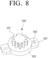
- FIG. 8 is a perspective view illustrating an oil damper of the rotary knob assembly capable of up-and-down motion of FIG. 1 .
- FIG. 9 is a bottom perspective view illustrating a slide cam of the rotary knob assembly capable of up-and-down motion of FIG. 1 .
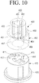
- FIG. 10 is an exploded perspective view illustrating a rotary sleeve of the rotary knob assembly capable of up-and-down motion of FIG. 1 , and FIG.
- FIG. 11 is a cross-sectional view illustrating a state in which the rotary sleeve of FIG. 10 is assembled.
- FIG. 12 is an exploded perspective view illustrating an up-and-down moving sleeve of the rotary knob assembly capable of up-and-down motion of FIG. 1
- FIG. 13 is an exploded perspective view illustrating a rotary knob of the rotary knob assembly capable of up-and-down motion of FIG. 1
- FIG. 14 is a cross-sectional view illustrating a state in which the rotary knob of FIG. 13 is assembled.
- a rotary knob assembly 1 capable of up-and-down motion according to an exemplary embodiment includes a case 100, a slide cam 200, an elastic member 300, a rotary sleeve 400, an up-and-down moving sleeve 600, and a rotary knob 700.
- the up-and-down movement may include the rotary knob moving into and out of a case or housing. That is, the up-and-down movement may include movement in a horizontal direction, a vertical direction, or a combination thereof.
- the case 100 creates a frame for the rotary knob assembly 1 which is capable of up-and-down motion according to an embodiment of the present disclosure, and accommodates the slide cam 200, the elastic member 300, the rotary sleeve 400, the up-and-down moving sleeve 600, and the rotary knob 700.
- the rotary knob assembly 1 may be disposed inside a device such as an audio player, for example, a receiver, a television, a DVD player, a game console, a Bluray player, a computer, and the like.
- the case 100 may be formed of a shape that has a substantially rectangular cross-section, and which includes an upper case 150 and a knob hole 151 through which the rotary knob 700 projects, and a lower case 110 which is removably coupled to the upper case 150 and supports the slide cam 200 which is movable.
- the upper case 150 and the lower case 110 may be formed such that they are coupled by one-touch.
- the upper case 150 and the lower case 110 may be coupled by a hook connection.
- the lower case 110 may be provided with two hooks 111 in a diagonal direction
- the upper case 150 may be provided with two catching portions 153 in which the two hooks 111 of the lower case 110 are caught.
- the hook connection of the upper case 150 and the lower case 110 is merely for purposes of example, and it should be appreciated that the upper case 150 and the lower case 110 may be coupled by various ways, such as a screw connection, and the like.
- the upper case 150 may include a plurality of fixing brackets 155 which are used to secure the rotary knob assembly 1 to another device.
- the fixing brackets 155 may include a fixing hole 156 in which a screw or a bolt may be inserted.
- the knob hole 151 in which a rotary knob 700 is disposed may protrude from and be formed in a bottom surface 157 ( FIG. 3 ) of the upper case 150.
- the bottom surface 157 of the upper case 150 may limit the vertical movement of the rotary knob 700 that is inserted in the knob hole 151.
- the lower case 110 supports the slide cam 200 so that the slide cam 200 may move linearly within the lower case 110. Also, the lower case 110 supports the rotary sleeve 400 so that the rotary sleeve 400 can perform a rotary movement.
- the slide cam 200 may be disposed on the upper side of the bottom surface 113 of the lower case 110 so that the slide cam 200 can slide in approximately a straight line with respect to the bottom surface 113.
- the bottom surface 113 of the lower case 110 may include a damper hole 115 through which a pinion gear 551 of an oil damper 550 projects and a sleeve hole 117 through which the rotary sleeve 400 projects.
- the sleeve hole 117 may have an inner diameter that is smaller than an outer diameter of a rotary flange 420 provided in a lower end of the rotary sleeve 400 so that the rotary flange 420 can not pass through the sleeve hole 117.
- a pair of supporting brackets 119 that guide the movement of the up-and-down moving sleeve 600 and limits right and left shaking of the up-and-down moving sleeve 600 may be disposed around the sleeve hole 117.
- the lower side of the bottom surface 113 of the lower case 110 includes a fixing ring receiving portion 120 in which a fixing ring 500 to support the rotary flange 420 of the rotary sleeve 400 to rotate, is disposed.
- the fixing ring 500 may be formed substantially in a ring shape.
- the inner diameter of the fixing ring 500 is formed to be greater than the outer diameter of the rotary flange 420 so that the rotary sleeve 400 can rotate.
- a rotary sleeve supporting portion 510 is provided inside the fixing ring 500. Accordingly, if the fixing ring 500 is disposed in the fixing ring receiving portion 120 of the lower case 110, as illustrated in the example of FIG. 3 , a space in which the rotary flange 420 of the rotary sleeve 400 can rotate may be formed between the bottom surface 113 of the lower case 110 and the rotary sleeve supporting portion 510 of the fixing ring 500. Accordingly, because the rotary sleeve 400 is supported by the fixing ring 500 disposed in the lower case 110, the rotary sleeve 400 may rotate freely with respect to the lower case 110 without being separated from the lower case 110.
- a volume circuit board 920 may be disposed at a top end of the fixing ring receiving portion 120 of the lower case 110.
- a plurality of female screw portions 122 may be provided in an outer peripheral surface of the fixing ring receiving portion 120.
- three female screw portions 122 are provided. Accordingly, the volume circuit board 920 may be fixed to the female screw portions 122 of the lower case 110 by a plurality of screws or bolts. If the volume circuit board 920 is fixed to the lower case 110, the fixing ring 500 may not come out from the fixing ring receiving portion 120 of the lower case 110.
- the volume circuit board 920 may be a printed circuit board in which a variable volume 900 is disposed.
- the variable volume 900 may be fixed to a surface of the volume circuit board 920, and a wire or a flexible cable (not illustrated) may be connected to the other surface of the volume circuit board 920.
- the volume circuit board 920 may serve to fix the fixing ring 500 to the fixing ring receiving portion 120 of the lower case 110.
- a rotation shaft 910 is disposed in a top surface of the variable volume 900. Accordingly, if the rotation shaft 910 is rotated, the volume is varied. In detail, if the rotation shaft 910 is rotated in one direction, the volume is increased, and, if the rotation shaft 910 is rotated in the opposite direction, the volume is decreased.
- variable volume 900 may use related variable volumes. Accordingly, descriptions for the structure and operation of the variable volume 900 are omitted.
- the rotation shaft 910 of the variable volume 900 is connected to the bottom end of the rotary sleeve 400 so that the rotation shaft 910 is rotated integrally with the rotary sleeve 400.
- the fixing ring 500 is fixed to the lower case 110 by the volume circuit board 920.
- the rotary knob assembly 1 capable of up-and-down motion may be used not only to control the volume.
- the rotary knob assembly 1 capable of up-and-down motion according to an exemplary embodiment may be configured so that an output variable element output of which is changed by rotation of a rotation shaft instead of the variable volume 900 is disposed in the printed circuit board 920 and the rotation shaft of the output variable element is rotated by the rotary sleeve 400.
- an oil damper 550 is disposed at a side of the fixing ring 500 in the lower side of the bottom surface 113 of the lower case 110.
- the oil damper 550 may control a moving speed of the slide cam 200.
- the oil damper 550 includes a pinion gear 551, and an oil tank 553 where the pinion gear 551 is rotatably disposed.
- the oil tank 553 includes oil therein.
- a rotating member (not illustrated) that rotates coaxially with the pinion gear 551 may be disposed inside the oil tank 553. In this example, when the pinion gear 551 rotates, the rotating member is rotated integrally with the pinion gear 551.
- the rotational speed of the pinion gear 551 may be slowed due to a viscosity resistance of the oil applied to the rotating member while it is submerged in the oil of the oil tank 553. Accordingly, when the pinion gear 551 is rotated by a certain force that is applied to the pinion gear 551, the pinion gear 551 may be rotated slower than a pinion gear which is not connected to the oil tank 553 due to the viscosity resistance of the oil.
- the oil damper 550 is disposed such that the pinion gear 551 projects through the damper hole 115 that is formed in the bottom surface 113 of the lower case 110.
- the oil tank 553 may be provided with at least one fixing bracket 557 in which a through hole 555 is formed.
- the oil damper 550 may be fixed to the bottom surface 113 of the lower case 110 by the fixing brackets 557 and screws.
- the slide cam 200 is disposed such that it can slidably move in a straight line with respect to the bottom surface 113 of the lower case 110, and is formed in a substantially flattened U shape.
- the slide cam 200 includes a base plate 210 and two side walls 220 extending upwardly from the base plate 210.
- the two side walls 220 are formed facing each other in parallel, and each side wall 220 is provided with a cam groove 230 that is inclined in an upward direction.
- a top end of the cam groove 230 is open such that a pair of up-and-down cams 620 of the up-and-down moving sleeve 600 can be inserted into the cam grooves 230.
- the side walls 220 are formed to have a predetermined thickness to support the pair of up-and-down cams 620 that are inserted in the cam grooves 230, the side walls 220 can hide a downward movement of the pair of up-and-down cams 620 of the up-and-down moving sleeve 600 into a horizontal movement of the slide cam 200, whereas the side walls 220 can hide the horizontal movement of the slide cam 200 into an upward movement of the up-and-down moving sleeve 600.
- a rotary sleeve 400 disposed in the lower case 110 passes through a rotary sleeve through hole 211, and is formed in the base plate 210.
- the rotary sleeve through hole 211 may have an elongated hole shape so that, when the slide cam 200 is moved linearly, the slide cam 200 does not interfere with the rotary sleeve 400.
- a moving groove 213 in which the pinion gear 551 of the oil damper 550 is able to move is formed in parallel to the rotary sleeve through hole 211 in one side of the rotary sleeve through hole 211 in the bottom surface of the base plate 210.
- a rack gear 240 is formed on the side surface of the moving groove 213 to engage with the pinion gear 551 of the oil damper 550. Accordingly, if the slide cam 200 is moved, the pinion gear 551 of the oil damper 550 that is engaged with the rack gear 240 is rotated.
- An elastic member 300 which applies an elastic force that can overcome the viscous resistance of the oil damper 550 to the slide cam 200, is disposed between the slide cam 200 and the lower case 110.
- the elastic member 300 may be disposed between the side surface of the slide cam 200 on which the rack gear 240 is formed and the lower case 110 facing the side surface thereof.
- one end of the elastic member 300 is fixed to a first protrusion 241 that is formed on the side wall of the slide cam 200, and the other end of the elastic member 300 is fixed to a second protrusion 130 formed on the side wall of the lower case 110.
- the side wall of the lower case 110 may include a slot 131 to accommodate the elastic member 300 in the operating direction of the slide cam 200 so that the lower case 110 does not interfere with the operation of the elastic member 300.
- the elastic member 300 may be a coil spring.
- a secondary fixing hook 820 ( FIG. 9 ) is disposed in the lower side of the base plate 210 of the slide cam 200 in a moving direction of the slide cam 200.
- the bottom surface 113 of the lower case 110 includes a hook through hole 133 through which the secondary fixing hook 820 of the slide cam 200 can pass and which prevents the secondary fixing hook 820 from interfering with the lower case 110 during linear movement of the slide cam 200.
- a push-push latch 810 that may be coupled with the secondary fixing hook 820 is disposed adjacent to one end of the hook through hole 133 in the lower side of the bottom surface 113 of the lower case 110.
- the push-push latch 810 may hold a head portion 821 of the secondary fixing hook 820, and if the push-push latch 810 is pressed again by the secondary fixing hook 820, the push-push latch 810 may release the head portion 821 of the secondary fixing hook 820.
- the slide cam 200 may be coupled to the lower case 110 or may release the engagement with the lower case 110 with a single touch by the linear movement of the slide cam 200.
- a conventional push-push latch may be used as the push-push latch 810.
- the secondary fixing hook 820 is disposed in the slide cam 200, and the push-push latch 810 is disposed in the lower case 110.
- the exemplary embodiments are not limited to the installation of the secondary fixing hook 820 and the push-push latch 810.
- the secondary fixing hook 820 may be disposed in the lower case 110, and the push-push latch 810 may be disposed in the slide cam 200.
- the rotary sleeve 400 supports the up-and-down moving sleeve 600 so that it can move up and down.
- the rotary sleeve 400 is formed such that it can rotate a rotating object, for example, the rotation shaft 910 of the variable volume 900.
- the rotary sleeve 400 may include a lower rotary sleeve 410 and an upper rotary sleeve 450.
- the lower rotary sleeve 410 may be formed of a hollow cylindrical shape, and may include a rotary flange 420 at a bottom end of the lower rotary sleeve 410.
- the rotary flange 420 may include a size that does not pass through the sleeve hole 117 of the lower case 110, and is supported by the fixing ring 500. Because the rotary flange 420 of the lower rotary sleeve 410 rotates in a space between the fixing ring receiving portion 120 and the fixing ring 500 of the lower case 110, the lower rotary sleeve 410 may not separate from the lower case 110, and may rotate with respect to the lower case 110.
- a hollow 411 of the lower rotary sleeve 410 is formed in a fixing groove to fix the rotation shaft 910 of the variable volume 900.
- the rotation shaft 910 of the variable volume 900 is machined as a D-cut, in which the hollow 411 of the lower rotary sleeve 410 is formed in a fixing groove which can receive the D-cut portion of the rotation shaft 910. Accordingly, if the rotation shaft 910 of the variable volume 900 is coupled to the fixing groove 411 of the lower rotary sleeve 410, and the lower rotary sleeve 410 is rotated, the rotation shaft 910 may be rotated along with the lower rotary sleeve 410.
- a plurality of inclined teeth 414 are formed around the hollow 411 of the top end of the lower rotary sleeve 410. Referring to the example of FIG. 10 , six inclined teeth 414 are formed, and the inclined teeth 414 are spaced apart by a predetermined interval.
- a plurality of fixing holes 417 are formed concentrically with the hollow 411 along the outside of the plurality of inclined teeth 414. The plurality of fixing holes 417 are used to combine the lower rotary sleeve 410 and the upper rotary sleeve 450 so that they are not separated from each other.
- the upper rotary sleeve 450 is formed of a hollow cylindrical shape, and is coupled to the lower rotary sleeve 410.
- the upper rotary sleeve 450 may be formed in a two-stage structure having different outer diameters.
- a lower portion 451 of the upper rotary sleeve 450 is coupled to the lower rotary sleeve 410 and is formed to have the same outer diameter as the outer diameter of the lower rotary sleeve 410 or an outer diameter similar to the outer diameter of the lower rotary sleeve 410.
- An upper portion 452 of the upper rotary sleeve 450 is formed to have an outer diameter that is smaller than that of the lower portion 451.
- a ring-shaped spring groove 453 may be formed between the upper portion 452 and the lower portion 451 of the upper rotary sleeve 450 so that a coil spring 350 may elastically support the rotary knob 700 and be disposed in the spring groove 453.
- the upper portion 452 of the upper rotary sleeve 450 includes a connecting hole 460 configured to receive a connecting member 760 of the rotary knob 700.
- the connecting hole 460 includes a central hole 461 and three slots 462 extending in a radial direction from the central hole 461.
- the central hole 461 and three slots 462 are formed to penetrate the upper portion 452 of the upper rotary sleeve 450.
- An example of the connecting member 760 of the rotary knob 700 is further described herein and may be inserted into the central hole 461 and three slots 462 of the upper rotary sleeve 450.
- a bottom surface of the upper portion 452 of the upper rotary sleeve 450 includes jaws 465 and receiving grooves 464 that are inclined in an upward direction between the slots 462.
- a side surface of the jaws 465 connected to the slot 462 is inclined upwardly toward the slot 462.
- Ribs 762 of the connecting member 760 of the rotary knob 700 are caught by the receiving grooves 464 of the bottom surface of the upper portion 452.
- the connecting member 760 has three ribs 762, and the connecting hole 460 in which the connecting member 760 is inserted has three slots 462.
- the connecting member 760 may be formed to have, one, two, three, four or more ribs 762, and the connecting hole 460 may be formed to have a number of slots 462 corresponding to the number of ribs 762.
- an inclined teeth receiving hole 470 (shown in FIG. 11 ) that has a diameter larger than a diameter of the central hole 461 of the upper portion 452 is formed in the lower portion 451 of the upper rotary sleeve 450.
- the inclined teeth receiving hole 470 may receive the plurality of inclined teeth 414 of the lower rotary sleeve 410, and is formed so that the connecting member 760 of the rotary knob 700 may be inserted into and rotate within the inclined teeth receiving hole 470.
- the inclined teeth receiving hole 470 of the lower portion 451 of the upper rotary sleeve 450 may include a receiving space in which the connecting member 760 of the rotary knob 700 freely rotates.
- a plurality of screw holes 457 may be formed around the inclined teeth receiving hole 470 in a bottom surface of the lower portion 451 of the upper rotary sleeve 450. If the upper rotary sleeve 450 is coupled to the top end of the lower rotary sleeve 410 and screws are fastened to the plurality of screw holes 457 through the fixing holes 417 of the lower rotary sleeve 410, the upper rotary sleeve 450 and the lower rotary sleeve 410 may be coupled together and rotate integrally.
- the up-and-down moving sleeve 600 is connected to the rotary knob 700, and is moved up and down according to a vertical movement of the rotary knob 700 which allows the slide cam 200 to move linearly in a horizontal direction.
- the up-and-down moving sleeve 600 may convert a linear movement in a vertical direction into a linear movement in the horizontal direction with the slide cam 200.
- the up-and-down moving sleeve 600 may include a hollow cylindrical shape, and may include a pair of up-and-down cams 620 in a low end portion of the side surface of the up-and-down moving sleeve 600.
- Each of the up-and-down cams 620 may include a bar shape having a circular cross-section.
- a distance 'd' between opposing ends of the pair of up-and-down cams 620 is formed so that the ends can be inserted into the top ends of the cam grooves 230 formed in the opposite side walls 220 of the slide cam 200 and to press the opposite side walls 220 of the slide cam 200 forming the cam groove 230. Accordingly, the pair of up-and-down cams 620 of the up-and-down moving sleeve 600 may be inserted into the cam groove 230 through the top end 231 of the slide cam 200, and press or otherwise apply pressure to the slide cam 200.
- the up-and-down moving sleeve 600 does not come out of the cam groove 230.
- the up-and-down moving sleeve 600 may include a sleeve body 610 that includes a pair of up-and-down cams 620 and a sleeve cap 650 that is coupled to the sleeve body 610.
- the pair of up-and-down cams 620 are included in the low end portion of the side surface of the sleeve body 610.
- a top end of the sleeve body 610 includes a connection step 611 that may be inserted in the sleeve cap 650.
- the sleeve body 610 includes a hollow cylindrical shape, and has an inner diameter in which the rotary sleeve 400 can be inserted.
- the rotary sleeve 400 may be inserted into the up-and-down moving sleeve 600.
- a pair of supporting grooves 613 are provided in a position that corresponds to the pair of supporting brackets 119 included in the bottom surface 113 of the lower case 110 in the side surface of the sleeve body 610. Accordingly, when the up-and-down moving sleeve 600 is moved up and down by the rotary knob 700, the up-and-down moving sleeve 600 can be moved, stably, for example, by a pair of supporting brackets 119 that are inserted in the pair of supporting grooves 613.
- the sleeve cap 650 is connected to the rotary knob 700 to allow the rotary knob 700 to rotate.
- the sleeve cap 650 is formed in a hollow cylindrical shape, and has a sleeve flange 660 in the top end of the sleeve cap 650.
- a plurality of coupling hooks 651 are formed in the inner surface of the sleeve cap 650. In this example, three coupling hooks 651 are provided.
- the plurality of coupling hooks 651 are formed such that they are hooked to the plurality of engaging jaws 615 formed in the inner surface of the connection step 611 of the sleeve body 610.
- a plurality of guide grooves 617 to guide the insertion of the plurality of coupling hooks 651 to the plurality of hooking jaws 615 are formed obliquely in the connection step 611 of the sleeve body 610.
- each of the plurality of coupling hooks 651 of the sleeve cap 650 may be moved downwardly along the guide grooves 617 of the sleeve body 610, and then may be caught by the hooking jaws 615.
- the sleeve cap 650 may be coupled to the sleeve body 610 so that the sleeve cap 650 is not separated from the sleeve body 610.
- the number of the coupling hooks 651 is not limited to three.
- the number of coupling hooks 651 may be one, two, three, four, or more.
- the rotary knob 700 is rotatably coupled to the up-and-down moving sleeve 600, and is configured to be moved up and down with respect to the upper case 150 by a force, for example, that is applied from the outside.
- the rotary knob 700 may include an upper rotary knob 750 and a lower rotary knob 710.
- the upper rotary knob 750 may be formed of a hollow cylindrical shape with a bottom.
- a connecting member 760 can be inserted in the connecting hole 460 of the rotary sleeve 400 and may be formed in the center of the bottom of the upper rotary knob 750.
- the connecting member 760 may be connected to a central axis 755 extending from the bottom of the upper rotary knob 750 by a screw.
- the connecting member 760 may be formed of a cylindrical body 761 and a plurality of ribs 762 extending radially from the surface of the body 761.
- a through hole (not illustrated) for screwing to the central axis 755 of the upper rotary knob 750 may be formed in the center of the body 761.
- the plurality of ribs 762 may be formed in a wedge shape so that the ribs 762 move smoothly along the slots 462 of the connecting hole 460 of the rotary sleeve 400. Also, the ribs 762 may be smoothly inserted into the slots 462 from the receiving grooves 464 of the bottom surface of the rotary sleeve 400.
- the connecting member 760 may include three ribs 762 in the same manner as the number of the slots 462 of the connecting hole 460 of the rotary sleeve 400. Accordingly, if the connecting member 760 of the rotary knob 700 is inserted into the connecting hole 460 of the rotary sleeve 400, the rotary knob 700 may be moved up and down with respect to the rotary sleeve 400. Also, if the connecting member 760 of the rotary knob 700 is located within the connecting hole 460 of the rotary sleeve 400, and the rotary knob 700 is rotated, the rotary sleeve 400 may be rotated together with the rotary knob 700.
- the connecting member 760 of the rotary knob 700 passes through the connecting hole 460 and is located in the inclined teeth receiving hole 470, the rotation of the rotary knob 700 may not be transmitted to the rotary sleeve 400.
- the connecting member 760 is formed separately from the upper rotary knob 750. However, this is merely for purposes of example, and it should be appreciated that the connecting member 760 may be formed integrally with the upper rotary knob 750.
- the side surface of the upper rotary knob 750 includes a plurality of fixing hooks 751 and a plurality of guide protrusions 753 that allow the upper rotary knob 750 to be detachably coupled to the lower rotary knob 710.
- the lower rotary knob 710 is formed of a hollow cylindrical shape, and includes an upper stem 711 and a lower stem 712. An outer diameter of the upper stem 711 is smaller than an outer diameter of the lower stem 712.
- the upper rotary knob 750 may be connected to the upper stem 711 of the lower rotary knob 710.
- the upper stem 711 of the lower rotary knob 710 includes a plurality of fixing grooves 731 by which the plurality of fixing hooks 751 of the upper rotary knob 750 are caught and a plurality of guide grooves 733 into which the plurality of guide protrusions 753 are inserted.
- each of the plurality of fixing hooks 751 may be caught by the fixing groove 731 so that the upper rotary knob 750 is connected to the lower rotary knob 710.
- a flange 720 is also provided in the bottom end of the lower rotary knob 710.
- the flange 720 of the lower rotary knob 710 is formed larger than the diameter of the knob hole 151 of the upper case 150. Accordingly, when the rotary knob 700 is moved upwardly with respect to the upper case 150, the flange 720 is caught by the bottom surface 157 of the upper case 150. Therefore, the flange 720 may function as a stopper to limit a rising distance of the rotary knob 700.
- the rotary knob 700 may be rotatably coupled to the up-and-down moving sleeve 600 so that the rotary knob 700 can move up and down with the up-and-down moving sleeve 600 while rotating with respect to the up-and-down moving sleeve 600.
- the sleeve cap 650 of the up-and-down moving sleeve 600 is inserted in the top end of the lower rotary knob 710, the upper rotary knob 750 is coupled to the lower rotary knob 710.
- the up-and-down moving sleeve 600 can rotate with respect to the rotary knob 700.
- the rotary knob 700 can be moved up and down along with the up-and-down moving sleeve 600 by vertical movement of the up-and-down moving sleeve 600.
- the rotary knob 700 may be elastically supported by the coil spring 350 disposed in the spring groove 453 of the rotary sleeve 400 that passes through the inside of the up-and-down moving sleeve 600.
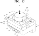
- FIG. 15 is a diagram illustrating a state in which a rotary knob of the rotary knob assembly capable of up-and-down motion of FIG. 1 is pressed according to an exemplary embodiment.
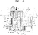
- FIG. 16 is a cross-sectional view illustrating the rotary knob assembly capable of up-and-down motion taken along line 16-16 of FIG. 15
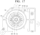
- FIG. 17 is a cross-sectional view illustrating the rotary knob assembly capable of up-and-down motion taken along line 17-17 of FIG. 16 .
- FIG. 16 is a cross-sectional view illustrating the rotary knob assembly capable of up-and-down motion taken along line 16-16 of FIG. 15
- FIG. 17 is a cross-sectional view illustrating the rotary knob assembly capable of up-and-down motion taken along line 17-17 of FIG. 16 .
- FIG. 18 is a view illustrating a relationship between an up-and-down cam of an up-and-down moving sleeve and a cam groove of a slide cam in which a rotary knob of a rotary knob assembly capable of up-and-down motion according to an exemplary embodiment protrudes.
- FIG. 19 is a view illustrating a relationship between an up-and-down cam of an up-and-down moving sleeve and a cam groove of a slide cam in which a rotary knob of a rotary knob assembly capable of up-and-down motion according to an exemplary embodiment is pressed.
- FIG. 20 is a view illustrating a relationship between an oil damper and a rack gear of a slide cam in which a rotary knob of a rotary knob assembly capable of up-and-down motion protrudes
- FIG. 21 is a view illustrating a relationship between an oil damper and a rack gear of a slide cam in which a rotary knob of a rotary knob assembly capable of up-and-down motion is pressed.
- a slide cam, an oil damper, and an elastic member are only illustrated, however, these examples may include other components that are not illustrated.
- a user can rotate the rotary knob 700 to adjust the volume.
- the rotary knob 700 may be inserted into the inside of the panel 3 so that the top surface of the rotary knob 700 is located at the same height as or at a height that is similar to the height of the panel 3.
- the panel 3 of the device in which rotary knob assembly 1 is disposed is illustrated by phantom lines.
- the rotary knob assembly 1 may be secured to the panel 3 by the plurality of fixing brackets 155 provided in the upper case 150.
- the rotary knob 700 moves down.
- the connecting member 760 of the rotary knob 700 and the up-and-down moving sleeve 600 are also moved down along with the rotary knob 700.
- the connecting member 760 of the rotary knob 700 is moved down, the plurality of ribs 762 of the connecting member 760 are moved down along the slots 462 of the connecting hole 460 of the rotary sleeve 400, and come into contact with the plurality of inclined teeth 414 that are provided in the top end of the lower rotary sleeve 410.
- the ribs 762 When a force is continuously applied to the rotary knob 700 in the downward direction, the ribs 762 may be lowered along the inclined surfaces 415 of the inclined teeth 414, and the rotary sleeve 400 may be rotated by a predetermined angle as much as the ribs 762 are lowered along the inclined surface 415.
- the ribs 762 of the rotary knob 700 come out of the slots 462 of the rotary sleeve 400.
- the ribs 762 of the rotary knob 700 may be caught by the receiving grooves 464 formed in the bottom surface of the upper portion 452 of the upper rotary sleeve 450 between the plurality of slots 462.
- the rotary knob 700 may be caught by the rotary sleeve 400 so that the rotary knob 700 does not project outside the panel 3.
- the inclined surfaces 415 of the inclined teeth 414 of the rotary sleeve 400 are located below the ribs 762 of the rotary knob 700. Accordingly, if the rotary knob 700 is pressed again, the ribs 762 of the connecting member 760 of the rotary knob 700 may come into contact with the inclined surfaces 415 of the inclined teeth 414 of the rotary sleeve 400.
- the pair of up-and-down cams 620 of the up-and-down moving sleeve 600 apply a force (arrow F1) to the cam groove 230 of the slide cam 200 in the downward direction as illustrated in FIG. 18 .
- the pair of up-and-down cams 620 applies a force to the side walls 220 forming the inclined cam groove 230 of the slide cam 200 in the downward direction, the slide cam 200 receives a force in the horizontal direction and is moved in the horizontal direction on the lower case 110.
- the slide cam 200 moves towards a right side (a direction of arrow A) in the FIG. 18 so that the up-and-down cam 620 of the up-and-down moving sleeve 600 is located from a P1 position of FIG. 18 to a P2 position of a lower side of the cam groove 230 as illustrated in FIG. 19 .
- the up-and-down moving sleeve 600 is moved downward, and the up-and-down cams 620 of the up-and-down moving sleeve 600 are moved downward along the cam groove 230 of the slide cam 200. Also, when the up-and-down cams 620 of the up-and-down moving sleeve 600 are located at the P2 position as shown in FIG. 19 , the elastic member 300 provided on one side of the slide cam 200 is in a tension state.
- the rotary knob 700 does not project towards the outside. Accordingly, the top surface of the rotary knob 700 is located at the same height as or at a height similar to the height of the panel 3 as illustrated in FIG. 16 .
- the secondary fixing hook 820 of the slide cam 200 may be coupled to the push-push latch 810 of the lower case 110 so that the slide cam 200 may be fixed more stably to the lower case 110. Accordingly, the rotary knob 700 can stably remain in the pressed state.
- the push-push latch 810 and the secondary fixing hook 820 are additionally disposed in order to secure the slide cam 200 more stably. Accordingly, as another example, the rotary knob assembly 1 capable of up and down movement may be formed by omitting the push-push latch 810 and the secondary fixing hook 820.
- the ribs 762 of the connecting member 760 of the rotary knob 700 are located at the receiving grooves 464 of the rotary sleeve 400.
- the up-and-down cams 620 of the up-and-down moving sleeve 600 are located at the P2 position which is the lower part of the cam groove 230 of the slide cam 200 (see FIG. 19 ).
- the connecting member 760 of the rotary knob 700 and the up-and-down moving sleeve 600 are moved downward together. Because the up-and-down cams 620 of the up-and-down moving sleeve 600 are moved from the P2 position to a P3 position as shown in FIG. 19 , the rotary knob 700 can be moved down further from the state of FIG. 16 . In this example, the ribs 762 of the connecting member 760 get out of the receiving grooves 464 of the upper rotary sleeve 450, and are in contact with the inclined surfaces 415 of the inclined teeth 414 of the lower rotary sleeve 410.
- the ribs 762 of the connecting member 760 While the ribs 762 of the connecting member 760 are in contact with the inclined surfaces 415 of the inclined teeth 414 of the rotary sleeve 400, and if the force is continuously applied to the rotary knob 700 in the downward direction, the ribs 762 of the connecting member 760 push the inclined surfaces 415 of the inclined teeth 414 of the rotary sleeve 400 so that the rotary sleeve 400 is rotated by a predetermined angle. Accordingly, the slots 462 of the connecting hole 460 of the rotary sleeve 400 are located above the ribs 762 of the connecting member 760.
- the slide cam 200 moves in the horizontal direction by the elastic force of the elastic member 300 disposed between the lower case 110 and the slide cam 200.
- the up-and-down cams 620 of the up-and-down moving sleeve 600 receive a force (arrow F2) in the upward direction by the cam groove 230 of the slide cam 200 so that the up-and-down cams 620 are moved in the upward direction.
- the pinion gear 551 of the oil damper 550 that is engaged with the rack gear 240 of the slide cam 200 may be rotated.
- the rack gear 240 of the slide cam 200 is engaged with the pinion gear 551 of the oil damper 550 as illustrated in FIG. 21 .
- the elastic member 300 is in a tensioned state. After that, when the rotary knob 700 is pressed, the slide cam 200 is moved toward the left side in FIG. 21 as indicated by arrow B by the elastic force of the elastic member 300 so as to be in the state as illustrated in FIG. 20 .
- the elastic member 300 is a non-tensioned state. Accordingly, when the slide cam 200 is moved by the elastic member 300, the rotation of the pinion gear 551 engaged with the rack gear 240 is suppressed by the viscosity of the oil damper 550 so that the slide cam 200 is moved slowly with respect to the lower case 110. Accordingly, a moving speed of the slide cam 200 may be controlled by the oil damper 550.
- the up-and-down moving sleeve 600 When the up-and-down cams 620 of the up-and-down moving sleeve 600 are moved in an upward direction by the horizontal movement of the slide cam 200, the up-and-down moving sleeve 600 is also moved in the upward direction.
- the rotary knob 700 connected to the up-and-down moving sleeve 600 also is moved in the upward direction. Because the slide cam 200 for moving the up-and-down moving sleeve 600 upwardly is moved slowly in the horizontal direction by the oil damper 550, the up-and-down moving sleeve 600 is also slowly moved in the upward direction. Accordingly, because the up-and-down moving sleeve 600 is slowly moved in the upward direction, the rotary knob 700 is also slowly projected outside the panel 3.
- the upward movement of the rotary knob 700 may be limited by the flange 720 of the rotary knob 700.
- the flange 720 of the rotary knob 700 may be caught by the bottom surface 157 of the upper case 150 as illustrated in FIG. 3 so that the rising of the rotary knob 700 is limited.
- the connecting member 760 of the rotary knob 700 may be inserted in the connecting hole 460 of the rotary sleeve 400 as illustrated in FIG. 4 . Accordingly, the plurality of ribs 762 of the connecting member 760 may be inserted in the plurality of slots 462 of the connecting hole 460.
- the connecting member 760 of the rotary knob 700 when the connecting member 760 of the rotary knob 700 is rotated, the rotary sleeve 400 is also rotated together by the ribs 762 of the connecting member 760.
- the connecting member 760 of the rotary knob 700 may be rotated integrally with the rotary knob 700.
- the rotary sleeve 400 is also rotated together by the connecting member 760.
- the up-and-down moving sleeve 600 is not rotated. That is, even if the rotary sleeve 400 is rotated, the slide cam 200 and the lower case 110 are not rotated.
- the rotation shaft 910 of the variable volume 900 connected to the lower portion of the rotary sleeve 400 may be rotated integrally with the rotary sleeve 400. Accordingly, when the user rotates the rotary knob 700, the rotation shaft 910 of the variable volume 900 is rotated integrally with the rotary knob 700 such that the user can adjust the volume of the variable volume 900.
- the rotary knob 700 of the rotary knob assembly 1 may be located inside a device such that an edge of the rotary knob is substantially or approximately flush with the outside of the case. Also, when pressed by a user, the rotary knob 700 may smoothly project outward from the device. Accordingly, it is possible to increase the degree of freedom in designing the device using the rotary knob assembly 1.
- a projection of the rotary knob 700 by the elastic member 300 and the slide cam 200 may be slowly performed due to the oil damper 550, thereby giving users a luxurious feel.
Landscapes
- Physics & Mathematics (AREA)
- General Physics & Mathematics (AREA)
- Engineering & Computer Science (AREA)
- Automation & Control Theory (AREA)
- Mechanical Control Devices (AREA)
Description
- Apparatuses and methods consistent with exemplary embodiments relate to a rotary knob assembly, and more particularly, to a rotary knob assembly capable of a rotary motion and an up-and-down motion.
- Generally, acoustic devices such as audio players, and the like, have a volume controller for controlling a volume of sound. For example, three types of volume controllers may be used. The first type is a protruding type of volume controller, and is formed so that a rotary knob protrudes. In this example, a user can adjust the volume of sound by rotating or turning the rotary knob. Here, if the rotary knob is rotated in one direction, the volume of sound is increased, and if the rotary knob is rotated in the opposite direction, the volume of sound is reduced.
EP 1 528 585 A1DE 10 2009 033 903 A1 describes a foldaway controlling device having a damper housing containing damping fluid in which a rotor is mounted rotatably. - A second type of volume controller is a button type of volume controller which is typically provided with a sound up button and a sound down button which are separately formed. In this example, if the sound up button is pressed, the volume of sound is increased, and if the sound down button is pressed, the volume of sound is decreased.
- A third type of volume controller is a touch type of volume controller which is used in acoustic devices that have a touch screen. Similar to the example of the button type of volume controller, a sound up button image and a sound down button image are displayed on the touch screen. In this example, when a user touches the sound up button image, the volume of sound is increased, and when the user touches the sound down button image, the volume of sound is decreased.
- However, because the conventional volume controllers project outwardly or require the use of a touch screen, there is a limit in designing the acoustic device. Accordingly, a different type of volume controller is needed to increase the diversity of the design of the acoustic device.
- Exemplary embodiments overcome the above disadvantages and other disadvantages not described above. Also, an exemplary embodiment is not required to overcome the disadvantages described above, and an exemplary embodiment may not overcome any of the problems described above.
- The exemplary embodiments relate to a rotary knob assembly capable of up-and-down motion in which, when not in use, the rotary knob may be accommodated within a device and does not protrude. Furthermore, when in use, the rotary knob can be projected by one-touch and a projecting motion of the rotary knob is smooth.
- According to an aspect of an exemplary embodiment, there is provided a rotary knob assembly capable of up-and-down motion, including a lower case in which an oil damper is disposed; a rotary sleeve rotatably disposed with respect to the lower case, the rotary sleeve including a connecting hole; a slide cam that moves linearly with respect to the lower case, the slide cam including a pair of cam grooves which are inclined with respect to the lower case and a sleeve hole through which the rotary sleeve passes; an elastic member disposed between the slide cam and the lower case, the elastic member including a first end fixed to the lower case and a second end fixed to the slide cam; an up-and-down moving sleeve that moves up and down with respect to the rotary sleeve, the up-and-down moving sleeve including a pair of up-and-down cams that are inserted in the pair of cam grooves of the slide cam; a rotary knob that is rotatably connected to the up-and-down moving sleeve, the rotary knob including a connecting member that is inserted in the connecting hole of the rotary sleeve; and an upper case connected to an upper side of the lower case, the upper case being configured to limit up and down movement of the rotary knob, wherein a moving speed of the slide cam is controlled by the oil damper.
- The rotary knob assembly may include an output variable element including a rotation shaft connected to a bottom end of the rotary sleeve; and a printed circuit board in which the output variable element is disposed, the printed circuit board being fixed to the lower case.
- The output variable element may include a variable volume.
- The oil damper may include a pinion gear; and an oil tank rotatably supporting the pinion gear, the oil tank being filled with oil, wherein a rotation speed of the pinion gear may be slowed by a viscosity resistance of the oil in the oil tank.
- The slide cam may include a rack gear that is formed parallel to a moving direction of the slide cam and that is engaged with the pinion gear of the oil damper.
- The rotary knob may include an upper rotary knob including a hollow cylindrical shape with a bottom, and a lower rotary knob including a hollow cylindrical shape, wherein the connecting member may be formed at a center of the bottom of the upper rotary knob, and the upper rotary knob may be detachably coupled to the lower rotary knob.
- The lower rotary knob may include a flange that is caught by a bottom surface of the upper case.
- The up-and-down moving sleeve may include a sleeve cap including a hollow cylindrical shape, the sleeve cap including a sleeve flange caught by a top end of the lower rotary knob; and a sleeve body including a hollow cylindrical shape, the sleeve body may be coupled to the sleeve cap, and the pair of up-and-down cams may be formed in a lower portion of a side surface of the sleeve body.
- The rotary sleeve may include an upper rotary sleeve including the connecting hole and a receiving space in which the connecting member of the rotary knob is received; and a lower rotary sleeve coupled to the upper rotary sleeve and including a fixing groove in which a rotating object is inserted.
- The rotary sleeve may be rotatably disposed in the lower case by a fixing ring.
- A plurality of inclined teeth may be concentrically formed at a top end of the lower rotary sleeve.
- The connecting hole of the upper rotary sleeve may include a central hole and a plurality of slots extending from the central hole, and the connecting member of the rotary knob may include a body inserted in the central hole and a plurality of ribs that extend from the body and are inserted in the slots.
- A bottom surface of the upper rotary sleeve may include receiving grooves in which the ribs of the rotary knob are received.
- The rotary knob assembly may include an elastic member which is disposed between the rotary knob and the rotary sleeve, and which elastically supports the rotary knob.
- In response to the rotary knob being pressed once, the connecting member of the rotary knob may be caught by the rotary sleeve so that the rotary sleeve remains in a pressed state.
- In response to the rotary knob being pressed again, the connecting member of the rotary knob may get out of the rotary sleeve and project to an original position.
- The lower case may include a pair of supporting brackets to support an up and down movement of the up-and-down moving sleeve.
- The lower case may include a push-push latch, and a secondary fixing hook which is coupled to or separated from the push-push latch according to a movement of the slide cam may be formed in the slide cam.
- Other objects, advantages and salient features of the present disclosure will become apparent from the following detailed description, which, taken in conjunction with the annexed drawings, discloses the exemplary embodiments.
- These and/or other aspects and advantages of the present disclosure will become more apparent and more readily appreciated from the following description, taken in conjunction with the accompanying drawings, in which:
-
FIG. 1 is a diagram illustrating a rotary knob assembly capable of up-and-down motion according to an exemplary embodiment; -
FIG. 2 is an exploded perspective view illustrating the rotary knob assembly capable of up-and-down motion ofFIG. 1 according to an exemplary embodiment; -
FIG. 3 is a cross-sectional view illustrating the rotary knob assembly capable of up-and-down motion taken along line 3-3 inFIG. 1 , according to an exemplary embodiment; -
FIG. 4 is a cross-sectional view illustrating the rotary knob assembly capable of up-and-down motion taken along line 4-4 inFIG. 3 , according to an exemplary embodiment; -
FIG. 5 is a cross-sectional view illustrating the rotary knob assembly capable of up-and-down motion taken along line 5-5 inFIG. 3 , according to an exemplary embodiment; -
FIG. 6 is a diagram illustrating the rotary knob assembly capable of up-and-down motion ofFIG. 1 from which an upper case and a rotary knob are removed, according to an exemplary embodiment; -
FIG. 7 is a bottom perspective view illustrating a lower case of the rotary knob assembly capable of up-and-down motion ofFIG. 1 , according to an exemplary embodiment; -
FIG. 8 is a perspective view illustrating an oil damper of the rotary knob assembly capable of up-and-down motion ofFIG. 1 , according to an exemplary embodiment; -
FIG. 9 is a bottom perspective view illustrating a slide cam of the rotary knob assembly capable of up-and-down motion ofFIG. 1 , according to an exemplary embodiment; -
FIG. 10 is an exploded perspective view illustrating a rotary sleeve of the rotary knob assembly capable of up-and-down motion ofFIG. 1 , according to an exemplary embodiment; -
FIG. 11 is a cross-sectional view illustrating a state in which the rotary sleeve ofFIG. 10 is assembled, according to an exemplary embodiment; -
FIG. 12 is an exploded perspective view illustrating an up-and-down moving sleeve of the rotary knob assembly capable of up-and-down motion ofFIG. 1 , according to an exemplary embodiment; -
FIG. 13 is an exploded perspective view illustrating a rotary knob of the rotary knob assembly capable of up-and-down motion ofFIG. 1 , according to an exemplary embodiment; -
FIG. 14 is a cross-sectional view illustrating a state in which the rotary knob ofFIG. 13 is assembled; -
FIG. 15 is a perspective view illustrating a state in which a rotary knob of the rotary knob assembly capable of up-and-down motion ofFIG. 1 is pressed, according to an exemplary embodiment; -
FIG. 16 is a cross-sectional view illustrating the rotary knob assembly capable of up-and-down motion taken along line 16-16 ofFIG. 15 , according to an exemplary embodiment; -
FIG. 17 is a cross-sectional view illustrating the rotary knob assembly capable of up-and-down motion taken along line 17-17 ofFIG. 16 , according to an exemplary embodiment; -
FIG. 18 is a view illustrating a relationship between an up-and-down cam of an up-and-down moving sleeve and a cam groove of a slide cam of a rotary knob of a protruding rotary knob assembly capable of up-and-down motion according to an exemplary embodiment; -
FIG. 19 is a view illustrating a relationship between an up-and-down cam of an up-and-down moving sleeve and a cam groove of a slide cam when a rotary knob of a rotary knob assembly capable of up-and-down motion is pressed according to an exemplary embodiment; -
FIG. 20 is a view illustrating a relationship between an oil damper and a rack gear of a slide cam when a rotary knob of a rotary knob assembly capable of up-and-down motion protrudes according to an exemplary embodiment; and -
FIG. 21 is a view illustrating a relationship between an oil damper and a rack gear of a slide cam when a rotary knob of a rotary knob assembly capable of up-and-down motion is pressed according to an exemplary embodiment. - Throughout the drawings, like reference numerals will be understood to refer to like parts, components and structures.
- Hereinafter, certain exemplary embodiments will be described in detail with reference to the accompanying drawings.
- The matters defined herein, such as a detailed construction and elements thereof, are provided to assist a reader in a comprehensive understanding of the invention. Thus, it is apparent that one or more exemplary embodiments may be carried out without those specifically defined matters. Also, well-known functions and/or constructions may be omitted to provide a clear and concise description of the exemplary embodiments. Further, dimensions of various elements in the accompanying drawings may be arbitrarily increased or decreased for assisting in a comprehensive understanding.
-
FIG. 1 is a diagram illustrating a rotary knob assembly capable of up-and-down motion according to an exemplary embodiment, andFIG. 2 is an exploded perspective view illustrating the rotary knob assembly capable of up-and-down motion ofFIG. 1 .FIG. 3 is a cross-sectional view illustrating the rotary knob assembly capable of up-and-down motion taken along line 3-3 ofFIG. 1 ,FIG. 4 is a cross-sectional view illustrating the rotary knob assembly capable of up-and-down motion taken along line 4-4 ofFIG. 3 , andFIG. 5 is a cross-sectional view illustrating the rotary knob assembly capable of up-and-down motion taken along line 5-5 ofFIG. 3 .FIG. 6 is a plan view illustrating the rotary knob assembly capable of up-and-down motion ofFIG. 1 from which an upper case and a rotary knob are removed.FIG. 7 is a bottom perspective view illustrating a lower case of the rotary knob assembly capable of up-and-down motion ofFIG. 1 .FIG. 8 is a perspective view illustrating an oil damper of the rotary knob assembly capable of up-and-down motion ofFIG. 1 .FIG. 9 is a bottom perspective view illustrating a slide cam of the rotary knob assembly capable of up-and-down motion ofFIG. 1 .FIG. 10 is an exploded perspective view illustrating a rotary sleeve of the rotary knob assembly capable of up-and-down motion ofFIG. 1 , andFIG. 11 is a cross-sectional view illustrating a state in which the rotary sleeve ofFIG. 10 is assembled.FIG. 12 is an exploded perspective view illustrating an up-and-down moving sleeve of the rotary knob assembly capable of up-and-down motion ofFIG. 1 ,FIG. 13 is an exploded perspective view illustrating a rotary knob of the rotary knob assembly capable of up-and-down motion ofFIG. 1 , andFIG. 14 is a cross-sectional view illustrating a state in which the rotary knob ofFIG. 13 is assembled. - Referring to
FIGS. 1 through 6 , arotary knob assembly 1 capable of up-and-down motion according to an exemplary embodiment includes acase 100, aslide cam 200, anelastic member 300, arotary sleeve 400, an up-and-down movingsleeve 600, and arotary knob 700. For example, the up-and-down movement may include the rotary knob moving into and out of a case or housing. That is, the up-and-down movement may include movement in a horizontal direction, a vertical direction, or a combination thereof. - The
case 100 creates a frame for therotary knob assembly 1 which is capable of up-and-down motion according to an embodiment of the present disclosure, and accommodates theslide cam 200, theelastic member 300, therotary sleeve 400, the up-and-down movingsleeve 600, and therotary knob 700. As an example, therotary knob assembly 1 may be disposed inside a device such as an audio player, for example, a receiver, a television, a DVD player, a game console, a Bluray player, a computer, and the like. - The
case 100 may be formed of a shape that has a substantially rectangular cross-section, and which includes anupper case 150 and aknob hole 151 through which therotary knob 700 projects, and alower case 110 which is removably coupled to theupper case 150 and supports theslide cam 200 which is movable. Theupper case 150 and thelower case 110 may be formed such that they are coupled by one-touch. For example, theupper case 150 and thelower case 110 may be coupled by a hook connection. In this example, thelower case 110 may be provided with twohooks 111 in a diagonal direction, and theupper case 150 may be provided with two catchingportions 153 in which the twohooks 111 of thelower case 110 are caught. The hook connection of theupper case 150 and thelower case 110 is merely for purposes of example, and it should be appreciated that theupper case 150 and thelower case 110 may be coupled by various ways, such as a screw connection, and the like. - The
upper case 150 may include a plurality of fixingbrackets 155 which are used to secure therotary knob assembly 1 to another device. For example, inFIGS. 1 and2 , three fixingbrackets 155 are provided on an outer peripheral surface of theupper case 150. The fixingbrackets 155 may include a fixinghole 156 in which a screw or a bolt may be inserted. Also, theknob hole 151 in which arotary knob 700 is disposed, may protrude from and be formed in a bottom surface 157 (FIG. 3 ) of theupper case 150. Thebottom surface 157 of theupper case 150 may limit the vertical movement of therotary knob 700 that is inserted in theknob hole 151. - The
lower case 110 supports theslide cam 200 so that theslide cam 200 may move linearly within thelower case 110. Also, thelower case 110 supports therotary sleeve 400 so that therotary sleeve 400 can perform a rotary movement. For example, theslide cam 200 may be disposed on the upper side of thebottom surface 113 of thelower case 110 so that theslide cam 200 can slide in approximately a straight line with respect to thebottom surface 113. Thebottom surface 113 of thelower case 110 may include adamper hole 115 through which apinion gear 551 of anoil damper 550 projects and asleeve hole 117 through which therotary sleeve 400 projects. Thesleeve hole 117 may have an inner diameter that is smaller than an outer diameter of arotary flange 420 provided in a lower end of therotary sleeve 400 so that therotary flange 420 can not pass through thesleeve hole 117. A pair of supportingbrackets 119 that guide the movement of the up-and-down movingsleeve 600 and limits right and left shaking of the up-and-down movingsleeve 600 may be disposed around thesleeve hole 117. In the example ofFIG. 7 , the lower side of thebottom surface 113 of thelower case 110 includes a fixingring receiving portion 120 in which afixing ring 500 to support therotary flange 420 of therotary sleeve 400 to rotate, is disposed. - As illustrated in
FIG. 2 , the fixingring 500 may be formed substantially in a ring shape. In this example, the inner diameter of the fixingring 500 is formed to be greater than the outer diameter of therotary flange 420 so that therotary sleeve 400 can rotate. A rotarysleeve supporting portion 510 is provided inside the fixingring 500. Accordingly, if the fixingring 500 is disposed in the fixingring receiving portion 120 of thelower case 110, as illustrated in the example ofFIG. 3 , a space in which therotary flange 420 of therotary sleeve 400 can rotate may be formed between thebottom surface 113 of thelower case 110 and the rotarysleeve supporting portion 510 of the fixingring 500. Accordingly, because therotary sleeve 400 is supported by the fixingring 500 disposed in thelower case 110, therotary sleeve 400 may rotate freely with respect to thelower case 110 without being separated from thelower case 110. - A
volume circuit board 920 may be disposed at a top end of the fixingring receiving portion 120 of thelower case 110. For example, a plurality offemale screw portions 122 may be provided in an outer peripheral surface of the fixingring receiving portion 120. In this exemplary embodiment, threefemale screw portions 122 are provided. Accordingly, thevolume circuit board 920 may be fixed to thefemale screw portions 122 of thelower case 110 by a plurality of screws or bolts. If thevolume circuit board 920 is fixed to thelower case 110, the fixingring 500 may not come out from the fixingring receiving portion 120 of thelower case 110. - The
volume circuit board 920 may be a printed circuit board in which avariable volume 900 is disposed. Thevariable volume 900 may be fixed to a surface of thevolume circuit board 920, and a wire or a flexible cable (not illustrated) may be connected to the other surface of thevolume circuit board 920. Thevolume circuit board 920 may serve to fix the fixingring 500 to the fixingring receiving portion 120 of thelower case 110. Here, arotation shaft 910 is disposed in a top surface of thevariable volume 900. Accordingly, if therotation shaft 910 is rotated, the volume is varied. In detail, if therotation shaft 910 is rotated in one direction, the volume is increased, and, if therotation shaft 910 is rotated in the opposite direction, the volume is decreased. Thevariable volume 900 may use related variable volumes. Accordingly, descriptions for the structure and operation of thevariable volume 900 are omitted. Therotation shaft 910 of thevariable volume 900 is connected to the bottom end of therotary sleeve 400 so that therotation shaft 910 is rotated integrally with therotary sleeve 400. - According to various exemplary embodiments, the fixing
ring 500 is fixed to thelower case 110 by thevolume circuit board 920. However, this is merely for purposes of example. Therotary knob assembly 1 capable of up-and-down motion may be used not only to control the volume. For example, therotary knob assembly 1 capable of up-and-down motion according to an exemplary embodiment may be configured so that an output variable element output of which is changed by rotation of a rotation shaft instead of thevariable volume 900 is disposed in the printedcircuit board 920 and the rotation shaft of the output variable element is rotated by therotary sleeve 400. - In this example, an
oil damper 550 is disposed at a side of the fixingring 500 in the lower side of thebottom surface 113 of thelower case 110. Theoil damper 550 may control a moving speed of theslide cam 200. For example, as illustrated inFIG. 8 , theoil damper 550 includes apinion gear 551, and anoil tank 553 where thepinion gear 551 is rotatably disposed. Theoil tank 553 includes oil therein. Also, a rotating member (not illustrated) that rotates coaxially with thepinion gear 551 may be disposed inside theoil tank 553. In this example, when thepinion gear 551 rotates, the rotating member is rotated integrally with thepinion gear 551. Accordingly, the rotational speed of thepinion gear 551 may be slowed due to a viscosity resistance of the oil applied to the rotating member while it is submerged in the oil of theoil tank 553. Accordingly, when thepinion gear 551 is rotated by a certain force that is applied to thepinion gear 551, thepinion gear 551 may be rotated slower than a pinion gear which is not connected to theoil tank 553 due to the viscosity resistance of the oil. Also, theoil damper 550 is disposed such that thepinion gear 551 projects through thedamper hole 115 that is formed in thebottom surface 113 of thelower case 110. Theoil tank 553 may be provided with at least onefixing bracket 557 in which a throughhole 555 is formed. Theoil damper 550 may be fixed to thebottom surface 113 of thelower case 110 by the fixingbrackets 557 and screws. - The
slide cam 200 is disposed such that it can slidably move in a straight line with respect to thebottom surface 113 of thelower case 110, and is formed in a substantially flattened U shape. For example, referring toFIGS. 2 and9 , theslide cam 200 includes abase plate 210 and twoside walls 220 extending upwardly from thebase plate 210. Here, the twoside walls 220 are formed facing each other in parallel, and eachside wall 220 is provided with acam groove 230 that is inclined in an upward direction. A top end of thecam groove 230 is open such that a pair of up-and-downcams 620 of the up-and-down movingsleeve 600 can be inserted into thecam grooves 230. Because theside walls 220 are formed to have a predetermined thickness to support the pair of up-and-downcams 620 that are inserted in thecam grooves 230, theside walls 220 can hide a downward movement of the pair of up-and-downcams 620 of the up-and-down movingsleeve 600 into a horizontal movement of theslide cam 200, whereas theside walls 220 can hide the horizontal movement of theslide cam 200 into an upward movement of the up-and-down movingsleeve 600. - A
rotary sleeve 400 disposed in thelower case 110 passes through a rotary sleeve throughhole 211, and is formed in thebase plate 210. The rotary sleeve throughhole 211 may have an elongated hole shape so that, when theslide cam 200 is moved linearly, theslide cam 200 does not interfere with therotary sleeve 400. A movinggroove 213 in which thepinion gear 551 of theoil damper 550 is able to move is formed in parallel to the rotary sleeve throughhole 211 in one side of the rotary sleeve throughhole 211 in the bottom surface of thebase plate 210. Arack gear 240 is formed on the side surface of the movinggroove 213 to engage with thepinion gear 551 of theoil damper 550. Accordingly, if theslide cam 200 is moved, thepinion gear 551 of theoil damper 550 that is engaged with therack gear 240 is rotated. - An
elastic member 300 which applies an elastic force that can overcome the viscous resistance of theoil damper 550 to theslide cam 200, is disposed between theslide cam 200 and thelower case 110. For example, theelastic member 300 may be disposed between the side surface of theslide cam 200 on which therack gear 240 is formed and thelower case 110 facing the side surface thereof. Also, one end of theelastic member 300 is fixed to afirst protrusion 241 that is formed on the side wall of theslide cam 200, and the other end of theelastic member 300 is fixed to asecond protrusion 130 formed on the side wall of thelower case 110. Here, the side wall of thelower case 110 may include aslot 131 to accommodate theelastic member 300 in the operating direction of theslide cam 200 so that thelower case 110 does not interfere with the operation of theelastic member 300. Also, theelastic member 300 may be a coil spring. - A secondary fixing hook 820 (
FIG. 9 ) is disposed in the lower side of thebase plate 210 of theslide cam 200 in a moving direction of theslide cam 200. Thebottom surface 113 of thelower case 110 includes a hook throughhole 133 through which thesecondary fixing hook 820 of theslide cam 200 can pass and which prevents thesecondary fixing hook 820 from interfering with thelower case 110 during linear movement of theslide cam 200. A push-push latch 810 that may be coupled with thesecondary fixing hook 820 is disposed adjacent to one end of the hook throughhole 133 in the lower side of thebottom surface 113 of thelower case 110. If thesecondary fixing hook 820 presses on the push-push latch 810, the push-push latch 810 may hold ahead portion 821 of thesecondary fixing hook 820, and if the push-push latch 810 is pressed again by thesecondary fixing hook 820, the push-push latch 810 may release thehead portion 821 of thesecondary fixing hook 820. Accordingly, theslide cam 200 may be coupled to thelower case 110 or may release the engagement with thelower case 110 with a single touch by the linear movement of theslide cam 200. As a non limiting example, a conventional push-push latch may be used as the push-push latch 810. - In the above examples, the
secondary fixing hook 820 is disposed in theslide cam 200, and the push-push latch 810 is disposed in thelower case 110. However, the exemplary embodiments are not limited to the installation of thesecondary fixing hook 820 and the push-push latch 810. Although not illustrated, for example, thesecondary fixing hook 820 may be disposed in thelower case 110, and the push-push latch 810 may be disposed in theslide cam 200. - The
rotary sleeve 400 supports the up-and-down movingsleeve 600 so that it can move up and down. Therotary sleeve 400 is formed such that it can rotate a rotating object, for example, therotation shaft 910 of thevariable volume 900. Referring toFIGS. 10 and11 , therotary sleeve 400 may include a lowerrotary sleeve 410 and an upperrotary sleeve 450. - The lower
rotary sleeve 410 may be formed of a hollow cylindrical shape, and may include arotary flange 420 at a bottom end of the lowerrotary sleeve 410. Therotary flange 420 may include a size that does not pass through thesleeve hole 117 of thelower case 110, and is supported by the fixingring 500. Because therotary flange 420 of the lowerrotary sleeve 410 rotates in a space between the fixingring receiving portion 120 and the fixingring 500 of thelower case 110, the lowerrotary sleeve 410 may not separate from thelower case 110, and may rotate with respect to thelower case 110. A hollow 411 of the lowerrotary sleeve 410 is formed in a fixing groove to fix therotation shaft 910 of thevariable volume 900. In the example ofFIGS. 2 and5 , therotation shaft 910 of thevariable volume 900 is machined as a D-cut, in which the hollow 411 of the lowerrotary sleeve 410 is formed in a fixing groove which can receive the D-cut portion of therotation shaft 910. Accordingly, if therotation shaft 910 of thevariable volume 900 is coupled to the fixinggroove 411 of the lowerrotary sleeve 410, and the lowerrotary sleeve 410 is rotated, therotation shaft 910 may be rotated along with the lowerrotary sleeve 410. - A plurality of
inclined teeth 414 are formed around the hollow 411 of the top end of the lowerrotary sleeve 410. Referring to the example ofFIG. 10 , sixinclined teeth 414 are formed, and theinclined teeth 414 are spaced apart by a predetermined interval. A plurality of fixingholes 417 are formed concentrically with the hollow 411 along the outside of the plurality ofinclined teeth 414. The plurality of fixingholes 417 are used to combine the lowerrotary sleeve 410 and the upperrotary sleeve 450 so that they are not separated from each other. - The upper
rotary sleeve 450 is formed of a hollow cylindrical shape, and is coupled to the lowerrotary sleeve 410. For example, the upperrotary sleeve 450 may be formed in a two-stage structure having different outer diameters. In this example, alower portion 451 of the upperrotary sleeve 450 is coupled to the lowerrotary sleeve 410 and is formed to have the same outer diameter as the outer diameter of the lowerrotary sleeve 410 or an outer diameter similar to the outer diameter of the lowerrotary sleeve 410. Anupper portion 452 of the upperrotary sleeve 450 is formed to have an outer diameter that is smaller than that of thelower portion 451. A ring-shapedspring groove 453 may be formed between theupper portion 452 and thelower portion 451 of the upperrotary sleeve 450 so that acoil spring 350 may elastically support therotary knob 700 and be disposed in thespring groove 453. - The
upper portion 452 of the upperrotary sleeve 450 includes a connectinghole 460 configured to receive a connectingmember 760 of therotary knob 700. In this example, the connectinghole 460 includes acentral hole 461 and threeslots 462 extending in a radial direction from thecentral hole 461. Thecentral hole 461 and threeslots 462 are formed to penetrate theupper portion 452 of the upperrotary sleeve 450. An example of the connectingmember 760 of therotary knob 700 is further described herein and may be inserted into thecentral hole 461 and threeslots 462 of the upperrotary sleeve 450. A bottom surface of theupper portion 452 of the upperrotary sleeve 450 includesjaws 465 and receivinggrooves 464 that are inclined in an upward direction between theslots 462. A side surface of thejaws 465 connected to theslot 462 is inclined upwardly toward theslot 462.Ribs 762 of the connectingmember 760 of therotary knob 700 are caught by the receivinggrooves 464 of the bottom surface of theupper portion 452. In this example, the connectingmember 760 has threeribs 762, and the connectinghole 460 in which the connectingmember 760 is inserted has threeslots 462. However, this is merely for purposes of example, and it should be appreciated that the connectingmember 760 may be formed to have, one, two, three, four ormore ribs 762, and the connectinghole 460 may be formed to have a number ofslots 462 corresponding to the number ofribs 762. - In this example, an inclined teeth receiving hole 470 (shown in
FIG. 11 ) that has a diameter larger than a diameter of thecentral hole 461 of theupper portion 452 is formed in thelower portion 451 of the upperrotary sleeve 450. The inclinedteeth receiving hole 470 may receive the plurality ofinclined teeth 414 of the lowerrotary sleeve 410, and is formed so that the connectingmember 760 of therotary knob 700 may be inserted into and rotate within the inclinedteeth receiving hole 470. Accordingly, the inclinedteeth receiving hole 470 of thelower portion 451 of the upperrotary sleeve 450 may include a receiving space in which the connectingmember 760 of therotary knob 700 freely rotates. - Also, a plurality of screw holes 457 (shown in
FIG. 10 ) may be formed around the inclinedteeth receiving hole 470 in a bottom surface of thelower portion 451 of the upperrotary sleeve 450. If the upperrotary sleeve 450 is coupled to the top end of the lowerrotary sleeve 410 and screws are fastened to the plurality of screw holes 457 through the fixingholes 417 of the lowerrotary sleeve 410, the upperrotary sleeve 450 and the lowerrotary sleeve 410 may be coupled together and rotate integrally. - The up-and-down moving
sleeve 600 is connected to therotary knob 700, and is moved up and down according to a vertical movement of therotary knob 700 which allows theslide cam 200 to move linearly in a horizontal direction. For example, the up-and-down movingsleeve 600 may convert a linear movement in a vertical direction into a linear movement in the horizontal direction with theslide cam 200. The up-and-down movingsleeve 600 may include a hollow cylindrical shape, and may include a pair of up-and-downcams 620 in a low end portion of the side surface of the up-and-down movingsleeve 600. Each of the up-and-downcams 620 may include a bar shape having a circular cross-section. A distance 'd' between opposing ends of the pair of up-and-downcams 620 is formed so that the ends can be inserted into the top ends of thecam grooves 230 formed in theopposite side walls 220 of theslide cam 200 and to press theopposite side walls 220 of theslide cam 200 forming thecam groove 230. Accordingly, the pair of up-and-downcams 620 of the up-and-down movingsleeve 600 may be inserted into thecam groove 230 through thetop end 231 of theslide cam 200, and press or otherwise apply pressure to theslide cam 200. Because the upper side of theslide cam 200 is covered by theupper case 150, even in an example in which the up-and-down movingsleeve 600 is being moved up and down, the up-and-down movingsleeve 600 does not come out of thecam groove 230. - As illustrated in
FIG. 12 , the up-and-down movingsleeve 600 may include asleeve body 610 that includes a pair of up-and-downcams 620 and asleeve cap 650 that is coupled to thesleeve body 610. The pair of up-and-downcams 620 are included in the low end portion of the side surface of thesleeve body 610. A top end of thesleeve body 610 includes aconnection step 611 that may be inserted in thesleeve cap 650. Thesleeve body 610 includes a hollow cylindrical shape, and has an inner diameter in which therotary sleeve 400 can be inserted. Accordingly, if the up-and-down movingsleeve 600 descends, therotary sleeve 400 may be inserted into the up-and-down movingsleeve 600. In this example, a pair of supportinggrooves 613 are provided in a position that corresponds to the pair of supportingbrackets 119 included in thebottom surface 113 of thelower case 110 in the side surface of thesleeve body 610. Accordingly, when the up-and-down movingsleeve 600 is moved up and down by therotary knob 700, the up-and-down movingsleeve 600 can be moved, stably, for example, by a pair of supportingbrackets 119 that are inserted in the pair of supportinggrooves 613. - As illustrated in
FIG. 3 , thesleeve cap 650 is connected to therotary knob 700 to allow therotary knob 700 to rotate. Thesleeve cap 650 is formed in a hollow cylindrical shape, and has asleeve flange 660 in the top end of thesleeve cap 650. A plurality of coupling hooks 651 are formed in the inner surface of thesleeve cap 650. In this example, three coupling hooks 651 are provided. The plurality of coupling hooks 651 are formed such that they are hooked to the plurality of engagingjaws 615 formed in the inner surface of theconnection step 611 of thesleeve body 610. Also, a plurality ofguide grooves 617 to guide the insertion of the plurality of coupling hooks 651 to the plurality of hookingjaws 615 are formed obliquely in theconnection step 611 of thesleeve body 610. - Accordingly, if the
sleeve cap 650 is inserted in theconnection step 611 of thesleeve body 610, each of the plurality of coupling hooks 651 of thesleeve cap 650 may be moved downwardly along theguide grooves 617 of thesleeve body 610, and then may be caught by the hookingjaws 615. Thus, thesleeve cap 650 may be coupled to thesleeve body 610 so that thesleeve cap 650 is not separated from thesleeve body 610. In this example, the number of the coupling hooks 651 is not limited to three. For example, the number of coupling hooks 651 may be one, two, three, four, or more. - The
rotary knob 700 is rotatably coupled to the up-and-down movingsleeve 600, and is configured to be moved up and down with respect to theupper case 150 by a force, for example, that is applied from the outside. For example, as illustrated inFIGS. 13 and14 , therotary knob 700 may include an upperrotary knob 750 and a lowerrotary knob 710. - The upper
rotary knob 750 may be formed of a hollow cylindrical shape with a bottom. A connectingmember 760 can be inserted in the connectinghole 460 of therotary sleeve 400 and may be formed in the center of the bottom of the upperrotary knob 750. The connectingmember 760 may be connected to acentral axis 755 extending from the bottom of the upperrotary knob 750 by a screw. For example, the connectingmember 760 may be formed of acylindrical body 761 and a plurality ofribs 762 extending radially from the surface of thebody 761. A through hole (not illustrated) for screwing to thecentral axis 755 of the upperrotary knob 750 may be formed in the center of thebody 761. The plurality ofribs 762 may be formed in a wedge shape so that theribs 762 move smoothly along theslots 462 of the connectinghole 460 of therotary sleeve 400. Also, theribs 762 may be smoothly inserted into theslots 462 from the receivinggrooves 464 of the bottom surface of therotary sleeve 400. - As a non-limiting example, the connecting
member 760 may include threeribs 762 in the same manner as the number of theslots 462 of the connectinghole 460 of therotary sleeve 400. Accordingly, if the connectingmember 760 of therotary knob 700 is inserted into the connectinghole 460 of therotary sleeve 400, therotary knob 700 may be moved up and down with respect to therotary sleeve 400. Also, if the connectingmember 760 of therotary knob 700 is located within the connectinghole 460 of therotary sleeve 400, and therotary knob 700 is rotated, therotary sleeve 400 may be rotated together with therotary knob 700. If the connectingmember 760 of therotary knob 700 passes through the connectinghole 460 and is located in the inclinedteeth receiving hole 470, the rotation of therotary knob 700 may not be transmitted to therotary sleeve 400. In this example, the connectingmember 760 is formed separately from the upperrotary knob 750. However, this is merely for purposes of example, and it should be appreciated that the connectingmember 760 may be formed integrally with the upperrotary knob 750. - Referring again to
FIG. 13 , the side surface of the upperrotary knob 750 includes a plurality of fixinghooks 751 and a plurality ofguide protrusions 753 that allow the upperrotary knob 750 to be detachably coupled to the lowerrotary knob 710. - The lower
rotary knob 710 is formed of a hollow cylindrical shape, and includes anupper stem 711 and alower stem 712. An outer diameter of theupper stem 711 is smaller than an outer diameter of thelower stem 712. The upperrotary knob 750 may be connected to theupper stem 711 of the lowerrotary knob 710. Theupper stem 711 of the lowerrotary knob 710 includes a plurality of fixinggrooves 731 by which the plurality of fixinghooks 751 of the upperrotary knob 750 are caught and a plurality ofguide grooves 733 into which the plurality ofguide protrusions 753 are inserted. Accordingly, if the upperrotary knob 750 is inserted into theupper stem 711 of the lowerrotary knob 710, each of the plurality of fixinghooks 751 may be caught by the fixinggroove 731 so that the upperrotary knob 750 is connected to the lowerrotary knob 710. Aflange 720 is also provided in the bottom end of the lowerrotary knob 710. Theflange 720 of the lowerrotary knob 710 is formed larger than the diameter of theknob hole 151 of theupper case 150. Accordingly, when therotary knob 700 is moved upwardly with respect to theupper case 150, theflange 720 is caught by thebottom surface 157 of theupper case 150. Therefore, theflange 720 may function as a stopper to limit a rising distance of therotary knob 700. - The
rotary knob 700 may be rotatably coupled to the up-and-down movingsleeve 600 so that therotary knob 700 can move up and down with the up-and-down movingsleeve 600 while rotating with respect to the up-and-down movingsleeve 600. For example, referring toFIG. 3 , when thesleeve cap 650 of the up-and-down movingsleeve 600 is inserted in the top end of the lowerrotary knob 710, the upperrotary knob 750 is coupled to the lowerrotary knob 710. In this example, if thesleeve body 610 is coupled to thesleeve cap 650, the up-and-down movingsleeve 600 can rotate with respect to therotary knob 700. - Also, because the
sleeve flange 660 of the up-and-down movingsleeve 600 is located in a space between the lowerrotary knob 710 and the upperrotary knob 750 of therotary knob 700, therotary knob 700 can be moved up and down along with the up-and-down movingsleeve 600 by vertical movement of the up-and-down movingsleeve 600. In this example, therotary knob 700 may be elastically supported by thecoil spring 350 disposed in thespring groove 453 of therotary sleeve 400 that passes through the inside of the up-and-down movingsleeve 600. - Hereinafter, examples of the
rotary knob assembly 1 capable of up-and-down motion are described with reference toFIGS. 3 to 6 , andFIGS. 15 to 21 . -
FIG. 15 is a diagram illustrating a state in which a rotary knob of the rotary knob assembly capable of up-and-down motion ofFIG. 1 is pressed according to an exemplary embodiment.FIG. 16 is a cross-sectional view illustrating the rotary knob assembly capable of up-and-down motion taken along line 16-16 ofFIG. 15 , andFIG. 17 is a cross-sectional view illustrating the rotary knob assembly capable of up-and-down motion taken along line 17-17 ofFIG. 16 .FIG. 18 is a view illustrating a relationship between an up-and-down cam of an up-and-down moving sleeve and a cam groove of a slide cam in which a rotary knob of a rotary knob assembly capable of up-and-down motion according to an exemplary embodiment protrudes.FIG. 19 is a view illustrating a relationship between an up-and-down cam of an up-and-down moving sleeve and a cam groove of a slide cam in which a rotary knob of a rotary knob assembly capable of up-and-down motion according to an exemplary embodiment is pressed. - In the examples of
FIGS. 18 and19 , other components are not illustrated for convenience of description.FIG. 20 is a view illustrating a relationship between an oil damper and a rack gear of a slide cam in which a rotary knob of a rotary knob assembly capable of up-and-down motion protrudes, andFIG. 21 is a view illustrating a relationship between an oil damper and a rack gear of a slide cam in which a rotary knob of a rotary knob assembly capable of up-and-down motion is pressed. InFIGS. 20 and21 , for convenience of description, a slide cam, an oil damper, and an elastic member are only illustrated, however, these examples may include other components that are not illustrated. - In the
rotary knob assembly 1 capable of up-and-down motion as illustrated inFIG. 3 , when therotary knob 700 projects from apanel 3 of the a device, a user can rotate therotary knob 700 to adjust the volume. - In a state in which the
rotary knob 700 projects as illustrated inFIGS. 1 and3 , if the user presses therotary knob 700, therotary knob 700 may be inserted into the inside of thepanel 3 so that the top surface of therotary knob 700 is located at the same height as or at a height that is similar to the height of thepanel 3. InFIGS. 3 and16 , thepanel 3 of the device in whichrotary knob assembly 1 is disposed is illustrated by phantom lines. Therotary knob assembly 1 may be secured to thepanel 3 by the plurality of fixingbrackets 155 provided in theupper case 150. - Hereinafter, an example in which the
rotary knob 700 is pressed in a state in which therotary knob 700 projects as illustrated inFIG. 3 , is described with reference to drawings. - If a user presses the top surface of the
rotary knob 700, therotary knob 700 moves down. When therotary knob 700 is moved down, the connectingmember 760 of therotary knob 700 and the up-and-down movingsleeve 600 are also moved down along with therotary knob 700. When the connectingmember 760 of therotary knob 700 is moved down, the plurality ofribs 762 of the connectingmember 760 are moved down along theslots 462 of the connectinghole 460 of therotary sleeve 400, and come into contact with the plurality ofinclined teeth 414 that are provided in the top end of the lowerrotary sleeve 410. - When a force is continuously applied to the
rotary knob 700 in the downward direction, theribs 762 may be lowered along theinclined surfaces 415 of theinclined teeth 414, and therotary sleeve 400 may be rotated by a predetermined angle as much as theribs 762 are lowered along theinclined surface 415. When therotary sleeve 400 is rotated by the predetermined angle, theribs 762 of therotary knob 700 come out of theslots 462 of therotary sleeve 400. - Accordingly, if the user removes the force applied to the
rotary knob 700, as illustrated inFIG. 16 , theribs 762 of therotary knob 700 may be caught by the receivinggrooves 464 formed in the bottom surface of theupper portion 452 of the upperrotary sleeve 450 between the plurality ofslots 462. Here, therotary knob 700 may be caught by therotary sleeve 400 so that therotary knob 700 does not project outside thepanel 3. In this example, theinclined surfaces 415 of theinclined teeth 414 of therotary sleeve 400 are located below theribs 762 of therotary knob 700. Accordingly, if therotary knob 700 is pressed again, theribs 762 of the connectingmember 760 of therotary knob 700 may come into contact with theinclined surfaces 415 of theinclined teeth 414 of therotary sleeve 400. - Also, when the up-and-down moving
sleeve 600 is moved downward by therotary knob 700, the pair of up-and-downcams 620 of the up-and-down movingsleeve 600 apply a force (arrow F1) to thecam groove 230 of theslide cam 200 in the downward direction as illustrated inFIG. 18 . When the pair of up-and-downcams 620 applies a force to theside walls 220 forming theinclined cam groove 230 of theslide cam 200 in the downward direction, theslide cam 200 receives a force in the horizontal direction and is moved in the horizontal direction on thelower case 110. For example, if the up-and-downcams 620 of the up-and-down movingsleeve 600 apply a force to theside walls 220 forming thecam groove 230 of theslide cam 200 in the downward direction (arrow F1 inFIG. 18 ) due to therotary knob 700, theslide cam 200 moves towards a right side (a direction of arrow A) in theFIG. 18 so that the up-and-down cam 620 of the up-and-down movingsleeve 600 is located from a P1 position ofFIG. 18 to a P2 position of a lower side of thecam groove 230 as illustrated inFIG. 19 . - In this example, if the
rotary knob 700 is moved downward, the up-and-down movingsleeve 600 is moved downward, and the up-and-downcams 620 of the up-and-down movingsleeve 600 are moved downward along thecam groove 230 of theslide cam 200. Also, when the up-and-downcams 620 of the up-and-down movingsleeve 600 are located at the P2 position as shown inFIG. 19 , theelastic member 300 provided on one side of theslide cam 200 is in a tension state. Here, even if theelastic member 300 is in a tension state, because the plurality ofribs 762 of the connectingmember 760 of therotary knob 700 are caught by the receivinggrooves 464 of therotary sleeve 400, therotary knob 700 does not project towards the outside. Accordingly, the top surface of therotary knob 700 is located at the same height as or at a height similar to the height of thepanel 3 as illustrated inFIG. 16 . - In an example of the
rotary knob assembly 1 capable of up-and-down movement in which thelower case 110 is provided with the push-push latch 810 and theslide cam 200 is provided with thesecondary fixing hook 820, when theslide cam 200 is moved in the horizontal direction by the lowering of therotary knob 700, thesecondary fixing hook 820 of theslide cam 200 may be coupled to the push-push latch 810 of thelower case 110 so that theslide cam 200 may be fixed more stably to thelower case 110. Accordingly, therotary knob 700 can stably remain in the pressed state. In this example, the push-push latch 810 and thesecondary fixing hook 820 are additionally disposed in order to secure theslide cam 200 more stably. Accordingly, as another example, therotary knob assembly 1 capable of up and down movement may be formed by omitting the push-push latch 810 and thesecondary fixing hook 820. - As illustrated in
FIG. 16 , in a state in which the top surface of therotary knob 700 is located in the same height as thepanel 3, if a user presses the top surface of therotary knob 700, therotary knob 700 projects from thepanel 3. - For example, when the top surface of the
rotary knob 700 is located at the same height as thepanel 3 or at a height similar to thepanel 3, as illustrated inFIG. 16 , theribs 762 of the connectingmember 760 of therotary knob 700 are located at the receivinggrooves 464 of therotary sleeve 400. Also, the up-and-downcams 620 of the up-and-down movingsleeve 600 are located at the P2 position which is the lower part of thecam groove 230 of the slide cam 200 (seeFIG. 19 ). - In this example, if the user presses the
rotary knob 700, the connectingmember 760 of therotary knob 700 and the up-and-down movingsleeve 600 are moved downward together. Because the up-and-downcams 620 of the up-and-down movingsleeve 600 are moved from the P2 position to a P3 position as shown inFIG. 19 , therotary knob 700 can be moved down further from the state ofFIG. 16 . In this example, theribs 762 of the connectingmember 760 get out of the receivinggrooves 464 of the upperrotary sleeve 450, and are in contact with theinclined surfaces 415 of theinclined teeth 414 of the lowerrotary sleeve 410. - While the
ribs 762 of the connectingmember 760 are in contact with theinclined surfaces 415 of theinclined teeth 414 of therotary sleeve 400, and if the force is continuously applied to therotary knob 700 in the downward direction, theribs 762 of the connectingmember 760 push theinclined surfaces 415 of theinclined teeth 414 of therotary sleeve 400 so that therotary sleeve 400 is rotated by a predetermined angle. Accordingly, theslots 462 of the connectinghole 460 of therotary sleeve 400 are located above theribs 762 of the connectingmember 760. - In this example, if the force applied to the
rotary knob 700 is removed, theslide cam 200 moves in the horizontal direction by the elastic force of theelastic member 300 disposed between thelower case 110 and theslide cam 200. In the example ofFIG. 19 , when theslide cam 200 is moved in the left direction (i.e. in a direction of arrow B) by theelastic member 300, the up-and-downcams 620 of the up-and-down movingsleeve 600 receive a force (arrow F2) in the upward direction by thecam groove 230 of theslide cam 200 so that the up-and-downcams 620 are moved in the upward direction. - When the
slide cam 200 is moved in the horizontal direction by theelastic member 300, thepinion gear 551 of theoil damper 550 that is engaged with therack gear 240 of theslide cam 200 may be rotated. For example, while therotary knob 700 is pressed as illustrated inFIG. 16 , therack gear 240 of theslide cam 200 is engaged with thepinion gear 551 of theoil damper 550 as illustrated inFIG. 21 . In this example, theelastic member 300 is in a tensioned state. After that, when therotary knob 700 is pressed, theslide cam 200 is moved toward the left side inFIG. 21 as indicated by arrow B by the elastic force of theelastic member 300 so as to be in the state as illustrated inFIG. 20 . At this time, theelastic member 300 is a non-tensioned state. Accordingly, when theslide cam 200 is moved by theelastic member 300, the rotation of thepinion gear 551 engaged with therack gear 240 is suppressed by the viscosity of theoil damper 550 so that theslide cam 200 is moved slowly with respect to thelower case 110. Accordingly, a moving speed of theslide cam 200 may be controlled by theoil damper 550. - When the up-and-down
cams 620 of the up-and-down movingsleeve 600 are moved in an upward direction by the horizontal movement of theslide cam 200, the up-and-down movingsleeve 600 is also moved in the upward direction. When the up-and-down movingsleeve 600 is moved in the upward direction, therotary knob 700 connected to the up-and-down movingsleeve 600 also is moved in the upward direction. Because theslide cam 200 for moving the up-and-down movingsleeve 600 upwardly is moved slowly in the horizontal direction by theoil damper 550, the up-and-down movingsleeve 600 is also slowly moved in the upward direction. Accordingly, because the up-and-down movingsleeve 600 is slowly moved in the upward direction, therotary knob 700 is also slowly projected outside thepanel 3. - The upward movement of the
rotary knob 700 may be limited by theflange 720 of therotary knob 700. For example, when therotary knob 700 is raised, theflange 720 of therotary knob 700 may be caught by thebottom surface 157 of theupper case 150 as illustrated inFIG. 3 so that the rising of therotary knob 700 is limited. In this example, the connectingmember 760 of therotary knob 700 may be inserted in the connectinghole 460 of therotary sleeve 400 as illustrated inFIG. 4 . Accordingly, the plurality ofribs 762 of the connectingmember 760 may be inserted in the plurality ofslots 462 of the connectinghole 460. - Accordingly, when the connecting
member 760 of therotary knob 700 is rotated, therotary sleeve 400 is also rotated together by theribs 762 of the connectingmember 760. In the state in which therotary knob 700 projects from thepanel 3 as illustrated inFIGS. 1 and3 , when the user rotates therotary knob 700, the connectingmember 760 of therotary knob 700 may be rotated integrally with therotary knob 700. When the connectingmember 760 of therotary knob 700 is rotated, therotary sleeve 400 is also rotated together by the connectingmember 760. However, even if therotary knob 700 is rotated, the up-and-down movingsleeve 600 is not rotated. That is, even if therotary sleeve 400 is rotated, theslide cam 200 and thelower case 110 are not rotated. - When the
rotary sleeve 400 is rotated, therotation shaft 910 of thevariable volume 900 connected to the lower portion of therotary sleeve 400 may be rotated integrally with therotary sleeve 400. Accordingly, when the user rotates therotary knob 700, therotation shaft 910 of thevariable volume 900 is rotated integrally with therotary knob 700 such that the user can adjust the volume of thevariable volume 900. - According to various exemplary embodiments, with the
rotary knob assembly 1 capable of up and down movement, therotary knob 700 of therotary knob assembly 1 may be located inside a device such that an edge of the rotary knob is substantially or approximately flush with the outside of the case. Also, when pressed by a user, therotary knob 700 may smoothly project outward from the device. Accordingly, it is possible to increase the degree of freedom in designing the device using therotary knob assembly 1. - Also, a projection of the
rotary knob 700 by theelastic member 300 and theslide cam 200 may be slowly performed due to theoil damper 550, thereby giving users a luxurious feel. - While the exemplary embodiments of the present disclosure have been described, additional variations and modifications of the exemplary embodiments may occur to those skilled in the art once they learn of the basic inventive concepts. Therefore, it is intended that the appended claims shall be construed to include both the above exemplary embodiments and all such variations and modifications.
Claims (15)
- A rotary knob assembly (1) capable of up and down movement comprising:a lower case (110) in which an oil damper (550) is disposed;a rotary sleeve (400) rotatably disposed with respect to the lower case (110), the rotary sleeve (400) provided with a connecting hole (460);a slide cam (200) disposed to be moved linearly with respect to the lower case (110), the slide cam (200) comprising a pair of cam grooves (230) which are inclined with respect to the lower case (110) and a sleeve hole (117) through which the rotary sleeve (400) passes;an elastic member (300) disposed between the slide cam (200) and the lower case (110), the elastic member (300) having a first end fixed to the lower case (110) and a second end fixed to the slide cam (200);an up-and-down moving sleeve (600) disposed to be moved up and down with respect to the rotary sleeve (400), the up-and-down moving sleeve (600) provided with a pair of up-and-down cams (620) that are inserted in the pair of cam grooves (230) of the slide cam (200);a rotary knob (700) that is rotatably connected to the up-and-down moving sleeve (600), the rotary knob (700) comprising a connecting member (760) that is inserted in the connecting hole (460) of the rotary sleeve (400); andan upper case (150) connected to an upper side of the lower case (110), the upper case (150) limiting up and down movement of the rotary knob (700),wherein a moving speed of the slide cam (200) is controlled by the oil damper (550).
- The rotary knob assembly (1) capable of up and down movement of claim 1, further comprising:an output variable element provided with a rotation shaft (910) connected to a bottom end of the rotary sleeve (400); anda printed circuit board (920) in which the output variable element is disposed, the printed circuit board (920) being fixed to the lower case (110).
- The rotary knob assembly (1) capable of up and down movement of claim 1, wherein the oil damper (550) comprises:a pinion gear (551); andan oil tank (553) rotatably supporting the pinion gear (551), the oil tank (553) being filled with oil,wherein a rotation speed of the pinion gear (551) is slowed by a viscosity resistance of the oil in the oil tank (553).
- The rotary knob assembly (1) capable of up and down movement of claim 3, wherein the slide cam (200) comprises a rack gear (240) that is formed parallel to a moving direction of the slide cam (200) and is engaged with the pinion gear of the oil damper (550).
- The rotary knob assembly (1) capable of up and down movement of claim 1, wherein the rotary knob (700) comprises:an upper rotary knob (750) formed in a hollow cylindrical shape with a bottom, anda lower rotary knob (710) formed in a hollow cylindrical shape,wherein the connecting member is formed at a center of the bottom of the upper rotary knob (750), and the upper rotary knob (750) is detachably coupled to the lower rotary knob (710).
- The rotary knob assembly (1) capable of up and down movement of claim 5, wherein the lower rotary knob (710) further comprises a flange (720) that is caught by a bottom surface (157) of the upper case (150).
- The rotary knob assembly (1) capable of up and down movement of claim 5, wherein the up-and-down moving sleeve (600) comprises,
a sleeve cap (650) formed in a hollow cylindrical shape, the sleeve cap (650) provided with a sleeve flange (660) caught by a top end of the lower rotary knob (710); and
a sleeve body (610) formed in a hollow cylindrical shape, the sleeve body (610) coupled to the sleeve cap (650),
wherein the pair of up-and-down cams (620) are formed in a lower portion of a side surface of the sleeve body (610). - The rotary knob assembly (1) capable of up and down movement of claim 1, wherein the rotary sleeve (400) comprises:an upper rotary sleeve (450) provided with the connecting hole (460) and a receiving space in which the connecting member of the rotary knob (700) is received; anda lower rotary sleeve (410) coupled to the upper rotary sleeve (450) and provided with a fixing groove (411) in which a rotating object is inserted.
- The rotary knob assembly (1) capable of up and down movement of claim 8, wherein the rotary sleeve (400) is rotatably disposed in the lower case (110) by a fixing ring (500).
- The rotary knob assembly (1) capable of up and down movement of claim 8, wherein a plurality of inclined teeth (414) are concentrically formed in a top end of the lower rotary sleeve.
- The rotary knob assembly (1) capable of up and down movement of claim 10, wherein
the connecting hole (460) of the upper rotary sleeve (450) comprises a central hole (461) and a plurality of slots (462) extending from the central hole, and
the connecting member of the rotary knob (700) comprises a body inserted in the central hole and a plurality of ribs (762) that extend from the body and that are inserted in the slots. - The rotary knob assembly (1) capable of up and down movement of claim 11, wherein a bottom surface of the upper rotary sleeve (450) is provided with receiving grooves (464) in which the ribs of the rotary knob (700) are received.
- The rotary knob assembly (1) capable of up and down movement of claim 1, further comprising an elastic member (300) which is disposed between the rotary knob (700) and the rotary sleeve (400), and which elastically support the rotary knob (700).
- The rotary knob assembly (1) capable of up and down movement of claim 1, wherein, when the rotary knob (700) is pressed once, the connecting member of the rotary knob (700) is caught by the rotary sleeve (400) so that the rotary sleeve (400) remains in a pressed state, and,
when the rotary knob (700) is pressed again, the connecting member of the rotary knob (700) project out of the rotary sleeve (400) and projects to an original position. - The rotary knob assembly (1) capable of up and down movement of claim 1, wherein
the lower case (110) is provided with a push-push latch (810), and
a secondary fixing hook (820) which is coupled to or separated from the push-push latch (810) according to a movement of the slide cam (200), is formed in the slide cam (200).
Applications Claiming Priority (1)
| Application Number | Priority Date | Filing Date | Title |
|---|---|---|---|
| KR1020140045916A KR20150120120A (en) | 2014-04-17 | 2014-04-17 | Rotary knob assembly capable of moving up and down |
Publications (2)
| Publication Number | Publication Date |
|---|---|
| EP2933811A1 EP2933811A1 (en) | 2015-10-21 |
| EP2933811B1 true EP2933811B1 (en) | 2017-03-08 |
Family
ID=53039199
Family Applications (1)
| Application Number | Title | Priority Date | Filing Date |
|---|---|---|---|
| EP15162749.4A Not-in-force EP2933811B1 (en) | 2014-04-17 | 2015-04-08 | Rotary knob assembly capable of up-and-down motion |
Country Status (5)
| Country | Link |
|---|---|
| US (1) | US9697967B2 (en) |
| EP (1) | EP2933811B1 (en) |
| KR (1) | KR20150120120A (en) |
| CN (1) | CN106170841B (en) |
| WO (1) | WO2015160133A1 (en) |
Families Citing this family (13)
| Publication number | Priority date | Publication date | Assignee | Title |
|---|---|---|---|---|
| US9595402B2 (en) * | 2014-07-17 | 2017-03-14 | Larry Vansickle | Single knob controller |
| EP3380912B1 (en) * | 2015-11-23 | 2021-10-06 | Bombardier Inc. | System for and method of controlling functions in a vehicle cabin |
| WO2017114650A1 (en) | 2015-12-28 | 2017-07-06 | Zound Industries International Ab | Multi-function control of one or several multimedia playback devices |
| KR101955358B1 (en) * | 2016-11-17 | 2019-03-06 | 에스엘 주식회사 | Automotive transmission |
| PL3447182T3 (en) * | 2017-08-25 | 2022-01-03 | Electrolux Appliances Aktiebolag | Household appliance and method for operating a household appliance |
| US10186387B1 (en) * | 2017-09-21 | 2019-01-22 | E.G.O. Elektro-Geraetebau Gmbh | Electrical control device |
| US10948056B2 (en) * | 2017-12-23 | 2021-03-16 | Continental Automotive Systems, Inc. | Elevation mechanism for a central input selector knob |
| CN207924234U (en) * | 2018-03-30 | 2018-09-28 | 深圳市大疆创新科技有限公司 | Knob mechanisms and with burnt remote controler |
| CN110761376B (en) * | 2019-11-01 | 2020-12-15 | 深圳贝迅科技有限公司 | Controller telescopic device and control method thereof |
| TWM593645U (en) * | 2019-12-18 | 2020-04-11 | 大陸商東莞琦聯電子有限公司 | Control device to generate rotation damping by using elastic force |
| CN111067370B (en) * | 2019-12-31 | 2024-04-12 | 德奥通用航空股份有限公司 | Knob switch and electric cooker |
| CN115312310B (en) * | 2022-08-15 | 2025-08-19 | 安徽莱特实业集团有限公司 | Automatic gear shifting device of dry-type transformer |
| KR102748275B1 (en) * | 2024-01-26 | 2024-12-31 | 최은진 | Rotary Switch Assembly |
Family Cites Families (13)
| Publication number | Priority date | Publication date | Assignee | Title |
|---|---|---|---|---|
| US1947282A (en) * | 1932-12-24 | 1934-02-13 | Amos H Theis | Manipulating device |
| US5384442A (en) * | 1993-01-05 | 1995-01-24 | Whirlpool Corporation | Control knob assembly for a cooking appliance |
| JP2000123684A (en) * | 1998-10-09 | 2000-04-28 | Mitsumi Electric Co Ltd | Rotary switch |
| KR20000033796A (en) * | 1998-11-25 | 2000-06-15 | 전주범 | Car audio reflector |
| JP4319890B2 (en) * | 2003-10-31 | 2009-08-26 | アルプス電気株式会社 | Compound operation mechanism |
| KR20050060831A (en) * | 2003-12-17 | 2005-06-22 | 현대모비스 주식회사 | Volume knob structure for a car audio |
| ES2294689T3 (en) * | 2004-03-30 | 2008-04-01 | Schneider Electric Industries Sas | ROTARY BUTTON FOR ELECTRIC CIRCUIT. |
| FR2868592B1 (en) * | 2004-03-30 | 2006-05-26 | Schneider Electric Ind Sas | ROTARY BUTTON FOR ELECTRIC CIRCUIT |
| DE102009006421A1 (en) * | 2009-01-22 | 2010-07-29 | E.G.O. Elektro-Gerätebau GmbH | Operating device for an electrical appliance |
| DE102009033903A1 (en) * | 2009-07-09 | 2011-01-13 | Illinois Tool Works Inc., Glenview | Foldaway controlling device for controlling e.g. oven, has damper housing containing damping fluid in which rotor is rotated or rotor comprising frictional element in friction-contact with surface of damper housing during rotation of rotor |
| JP6010754B2 (en) * | 2011-12-06 | 2016-10-19 | パナソニックIpマネジメント株式会社 | Push lock body and input device using the same |
| DE102012014535A1 (en) * | 2012-07-21 | 2014-01-23 | Diehl Ako Stiftung & Co. Kg | Rotary knob operating device |
| CN103148156A (en) * | 2013-03-15 | 2013-06-12 | 常州新瑞汽车配件制造有限公司 | Mechanical adjusting mechanism for damper |
-
2014
- 2014-04-17 KR KR1020140045916A patent/KR20150120120A/en not_active Abandoned
-
2015
- 2015-04-07 WO PCT/KR2015/003474 patent/WO2015160133A1/en not_active Ceased
- 2015-04-07 CN CN201580019432.XA patent/CN106170841B/en not_active Expired - Fee Related
- 2015-04-08 EP EP15162749.4A patent/EP2933811B1/en not_active Not-in-force
- 2015-04-17 US US14/689,535 patent/US9697967B2/en not_active Expired - Fee Related
Non-Patent Citations (1)
| Title |
|---|
| None * |
Also Published As
| Publication number | Publication date |
|---|---|
| WO2015160133A1 (en) | 2015-10-22 |
| US9697967B2 (en) | 2017-07-04 |
| CN106170841B (en) | 2018-12-28 |
| KR20150120120A (en) | 2015-10-27 |
| EP2933811A1 (en) | 2015-10-21 |
| US20150303009A1 (en) | 2015-10-22 |
| CN106170841A (en) | 2016-11-30 |
Similar Documents
| Publication | Publication Date | Title |
|---|---|---|
| US9697967B2 (en) | Rotary knob assembly capable of up-and-down motion | |
| US10206029B2 (en) | Omnidirectional speaker | |
| JP6189731B2 (en) | Shift device | |
| US10506890B2 (en) | Cup holder | |
| EP3367675B1 (en) | Image sound device having display portion that can appear/disappear | |
| JP2008154817A (en) | Power transmission device of game machine | |
| JP6028172B2 (en) | Push button device for gaming machines | |
| KR100485844B1 (en) | Navigation Switch Assembly | |
| CN105370115A (en) | Button-type glove-box lock structure | |
| JP2008171680A (en) | Combined operation type input device | |
| JP2013097363A (en) | Document press-contacting plate opening/closing device and office appliance | |
| WO2003036950A1 (en) | Wall-mounting device for television | |
| CN112905028B (en) | Roller device capable of rapidly switching flywheel modes | |
| KR20220122959A (en) | Rotary detent device for rotary knob and vehicular rotary switch unit having the same | |
| CN115738234B (en) | Rocker controller with knob and button functions | |
| JP2016087250A (en) | Game machine | |
| JP2009264436A (en) | Torque limiter device, and display screen turning device equipped therewith and tv device including the same | |
| JP4319890B2 (en) | Compound operation mechanism | |
| JP2015158970A (en) | multi-directional input device | |
| KR100632738B1 (en) | Portable computer | |
| CN113669356B (en) | Hinge device and various machines equipped with the hinge device | |
| JP2019093101A (en) | Furniture assembly including safety device | |
| JP6048830B2 (en) | Haptic multi-directional input device | |
| JP7578162B2 (en) | Switching device and electronic device | |
| CN113903609A (en) | Key with balance rod and hand controller |
Legal Events
| Date | Code | Title | Description |
|---|---|---|---|
| PUAI | Public reference made under article 153(3) epc to a published international application that has entered the european phase |
Free format text: ORIGINAL CODE: 0009012 |
|
| 17P | Request for examination filed |
Effective date: 20150408 |
|
| AK | Designated contracting states |
Kind code of ref document: A1 Designated state(s): AL AT BE BG CH CY CZ DE DK EE ES FI FR GB GR HR HU IE IS IT LI LT LU LV MC MK MT NL NO PL PT RO RS SE SI SK SM TR |
|
| AX | Request for extension of the european patent |
Extension state: BA ME |
|
| 17Q | First examination report despatched |
Effective date: 20151007 |
|
| GRAP | Despatch of communication of intention to grant a patent |
Free format text: ORIGINAL CODE: EPIDOSNIGR1 |
|
| INTG | Intention to grant announced |
Effective date: 20161021 |
|
| STAA | Information on the status of an ep patent application or granted ep patent |
Free format text: STATUS: GRANT OF PATENT IS INTENDED |
|
| GRAS | Grant fee paid |
Free format text: ORIGINAL CODE: EPIDOSNIGR3 |
|
| GRAA | (expected) grant |
Free format text: ORIGINAL CODE: 0009210 |
|
| STAA | Information on the status of an ep patent application or granted ep patent |
Free format text: STATUS: THE PATENT HAS BEEN GRANTED |
|
| AK | Designated contracting states |
Kind code of ref document: B1 Designated state(s): AL AT BE BG CH CY CZ DE DK EE ES FI FR GB GR HR HU IE IS IT LI LT LU LV MC MK MT NL NO PL PT RO RS SE SI SK SM TR |
|
| REG | Reference to a national code |
Ref country code: GB Ref legal event code: FG4D |
|
| REG | Reference to a national code |
Ref country code: CH Ref legal event code: EP Ref country code: AT Ref legal event code: REF Ref document number: 874203 Country of ref document: AT Kind code of ref document: T Effective date: 20170315 |
|
| REG | Reference to a national code |
Ref country code: IE Ref legal event code: FG4D |
|
| REG | Reference to a national code |
Ref country code: DE Ref legal event code: R096 Ref document number: 602015001704 Country of ref document: DE |
|
| REG | Reference to a national code |
Ref country code: LT Ref legal event code: MG4D |
|
| REG | Reference to a national code |
Ref country code: NL Ref legal event code: MP Effective date: 20170308 |
|
| PG25 | Lapsed in a contracting state [announced via postgrant information from national office to epo] |
Ref country code: LT Free format text: LAPSE BECAUSE OF FAILURE TO SUBMIT A TRANSLATION OF THE DESCRIPTION OR TO PAY THE FEE WITHIN THE PRESCRIBED TIME-LIMIT Effective date: 20170308 Ref country code: FI Free format text: LAPSE BECAUSE OF FAILURE TO SUBMIT A TRANSLATION OF THE DESCRIPTION OR TO PAY THE FEE WITHIN THE PRESCRIBED TIME-LIMIT Effective date: 20170308 Ref country code: GR Free format text: LAPSE BECAUSE OF FAILURE TO SUBMIT A TRANSLATION OF THE DESCRIPTION OR TO PAY THE FEE WITHIN THE PRESCRIBED TIME-LIMIT Effective date: 20170609 Ref country code: HR Free format text: LAPSE BECAUSE OF FAILURE TO SUBMIT A TRANSLATION OF THE DESCRIPTION OR TO PAY THE FEE WITHIN THE PRESCRIBED TIME-LIMIT Effective date: 20170308 Ref country code: NO Free format text: LAPSE BECAUSE OF FAILURE TO SUBMIT A TRANSLATION OF THE DESCRIPTION OR TO PAY THE FEE WITHIN THE PRESCRIBED TIME-LIMIT Effective date: 20170608 |
|
| REG | Reference to a national code |
Ref country code: AT Ref legal event code: MK05 Ref document number: 874203 Country of ref document: AT Kind code of ref document: T Effective date: 20170308 |
|
| PG25 | Lapsed in a contracting state [announced via postgrant information from national office to epo] |
Ref country code: ES Free format text: LAPSE BECAUSE OF FAILURE TO SUBMIT A TRANSLATION OF THE DESCRIPTION OR TO PAY THE FEE WITHIN THE PRESCRIBED TIME-LIMIT Effective date: 20170308 Ref country code: SE Free format text: LAPSE BECAUSE OF FAILURE TO SUBMIT A TRANSLATION OF THE DESCRIPTION OR TO PAY THE FEE WITHIN THE PRESCRIBED TIME-LIMIT Effective date: 20170308 Ref country code: LV Free format text: LAPSE BECAUSE OF FAILURE TO SUBMIT A TRANSLATION OF THE DESCRIPTION OR TO PAY THE FEE WITHIN THE PRESCRIBED TIME-LIMIT Effective date: 20170308 Ref country code: RS Free format text: LAPSE BECAUSE OF FAILURE TO SUBMIT A TRANSLATION OF THE DESCRIPTION OR TO PAY THE FEE WITHIN THE PRESCRIBED TIME-LIMIT Effective date: 20170308 Ref country code: BG Free format text: LAPSE BECAUSE OF FAILURE TO SUBMIT A TRANSLATION OF THE DESCRIPTION OR TO PAY THE FEE WITHIN THE PRESCRIBED TIME-LIMIT Effective date: 20170608 |
|
| PG25 | Lapsed in a contracting state [announced via postgrant information from national office to epo] |
Ref country code: NL Free format text: LAPSE BECAUSE OF FAILURE TO SUBMIT A TRANSLATION OF THE DESCRIPTION OR TO PAY THE FEE WITHIN THE PRESCRIBED TIME-LIMIT Effective date: 20170308 |
|
| PG25 | Lapsed in a contracting state [announced via postgrant information from national office to epo] |
Ref country code: RO Free format text: LAPSE BECAUSE OF FAILURE TO SUBMIT A TRANSLATION OF THE DESCRIPTION OR TO PAY THE FEE WITHIN THE PRESCRIBED TIME-LIMIT Effective date: 20170308 Ref country code: EE Free format text: LAPSE BECAUSE OF FAILURE TO SUBMIT A TRANSLATION OF THE DESCRIPTION OR TO PAY THE FEE WITHIN THE PRESCRIBED TIME-LIMIT Effective date: 20170308 Ref country code: IT Free format text: LAPSE BECAUSE OF FAILURE TO SUBMIT A TRANSLATION OF THE DESCRIPTION OR TO PAY THE FEE WITHIN THE PRESCRIBED TIME-LIMIT Effective date: 20170308 Ref country code: SK Free format text: LAPSE BECAUSE OF FAILURE TO SUBMIT A TRANSLATION OF THE DESCRIPTION OR TO PAY THE FEE WITHIN THE PRESCRIBED TIME-LIMIT Effective date: 20170308 Ref country code: AT Free format text: LAPSE BECAUSE OF FAILURE TO SUBMIT A TRANSLATION OF THE DESCRIPTION OR TO PAY THE FEE WITHIN THE PRESCRIBED TIME-LIMIT Effective date: 20170308 Ref country code: CZ Free format text: LAPSE BECAUSE OF FAILURE TO SUBMIT A TRANSLATION OF THE DESCRIPTION OR TO PAY THE FEE WITHIN THE PRESCRIBED TIME-LIMIT Effective date: 20170308 |
|
| PG25 | Lapsed in a contracting state [announced via postgrant information from national office to epo] |
Ref country code: PT Free format text: LAPSE BECAUSE OF FAILURE TO SUBMIT A TRANSLATION OF THE DESCRIPTION OR TO PAY THE FEE WITHIN THE PRESCRIBED TIME-LIMIT Effective date: 20170710 Ref country code: SM Free format text: LAPSE BECAUSE OF FAILURE TO SUBMIT A TRANSLATION OF THE DESCRIPTION OR TO PAY THE FEE WITHIN THE PRESCRIBED TIME-LIMIT Effective date: 20170308 Ref country code: IS Free format text: LAPSE BECAUSE OF FAILURE TO SUBMIT A TRANSLATION OF THE DESCRIPTION OR TO PAY THE FEE WITHIN THE PRESCRIBED TIME-LIMIT Effective date: 20170708 Ref country code: PL Free format text: LAPSE BECAUSE OF FAILURE TO SUBMIT A TRANSLATION OF THE DESCRIPTION OR TO PAY THE FEE WITHIN THE PRESCRIBED TIME-LIMIT Effective date: 20170308 |
|
| REG | Reference to a national code |
Ref country code: DE Ref legal event code: R097 Ref document number: 602015001704 Country of ref document: DE |
|
| PLBE | No opposition filed within time limit |
Free format text: ORIGINAL CODE: 0009261 |
|
| STAA | Information on the status of an ep patent application or granted ep patent |
Free format text: STATUS: NO OPPOSITION FILED WITHIN TIME LIMIT |
|
| REG | Reference to a national code |
Ref country code: IE Ref legal event code: MM4A |
|
| REG | Reference to a national code |
Ref country code: FR Ref legal event code: ST Effective date: 20171229 |
|
| PG25 | Lapsed in a contracting state [announced via postgrant information from national office to epo] |
Ref country code: MC Free format text: LAPSE BECAUSE OF FAILURE TO SUBMIT A TRANSLATION OF THE DESCRIPTION OR TO PAY THE FEE WITHIN THE PRESCRIBED TIME-LIMIT Effective date: 20170308 Ref country code: FR Free format text: LAPSE BECAUSE OF NON-PAYMENT OF DUE FEES Effective date: 20170509 Ref country code: DK Free format text: LAPSE BECAUSE OF FAILURE TO SUBMIT A TRANSLATION OF THE DESCRIPTION OR TO PAY THE FEE WITHIN THE PRESCRIBED TIME-LIMIT Effective date: 20170308 |
|
| 26N | No opposition filed |
Effective date: 20171211 |
|
| PG25 | Lapsed in a contracting state [announced via postgrant information from national office to epo] |
Ref country code: SI Free format text: LAPSE BECAUSE OF FAILURE TO SUBMIT A TRANSLATION OF THE DESCRIPTION OR TO PAY THE FEE WITHIN THE PRESCRIBED TIME-LIMIT Effective date: 20170308 Ref country code: LU Free format text: LAPSE BECAUSE OF NON-PAYMENT OF DUE FEES Effective date: 20170408 |
|
| REG | Reference to a national code |
Ref country code: BE Ref legal event code: MM Effective date: 20170430 |
|
| PG25 | Lapsed in a contracting state [announced via postgrant information from national office to epo] |
Ref country code: IE Free format text: LAPSE BECAUSE OF NON-PAYMENT OF DUE FEES Effective date: 20170408 |
|
| PG25 | Lapsed in a contracting state [announced via postgrant information from national office to epo] |
Ref country code: BE Free format text: LAPSE BECAUSE OF NON-PAYMENT OF DUE FEES Effective date: 20170430 |
|
| PG25 | Lapsed in a contracting state [announced via postgrant information from national office to epo] |
Ref country code: MT Free format text: LAPSE BECAUSE OF NON-PAYMENT OF DUE FEES Effective date: 20170408 |
|
| REG | Reference to a national code |
Ref country code: CH Ref legal event code: PL |
|
| PG25 | Lapsed in a contracting state [announced via postgrant information from national office to epo] |
Ref country code: LI Free format text: LAPSE BECAUSE OF NON-PAYMENT OF DUE FEES Effective date: 20180430 Ref country code: CH Free format text: LAPSE BECAUSE OF NON-PAYMENT OF DUE FEES Effective date: 20180430 |
|
| PGFP | Annual fee paid to national office [announced via postgrant information from national office to epo] |
Ref country code: GB Payment date: 20190321 Year of fee payment: 5 |
|
| PG25 | Lapsed in a contracting state [announced via postgrant information from national office to epo] |
Ref country code: HU Free format text: LAPSE BECAUSE OF FAILURE TO SUBMIT A TRANSLATION OF THE DESCRIPTION OR TO PAY THE FEE WITHIN THE PRESCRIBED TIME-LIMIT; INVALID AB INITIO Effective date: 20150408 |
|
| PGFP | Annual fee paid to national office [announced via postgrant information from national office to epo] |
Ref country code: DE Payment date: 20190320 Year of fee payment: 5 |
|
| PG25 | Lapsed in a contracting state [announced via postgrant information from national office to epo] |
Ref country code: CY Free format text: LAPSE BECAUSE OF FAILURE TO SUBMIT A TRANSLATION OF THE DESCRIPTION OR TO PAY THE FEE WITHIN THE PRESCRIBED TIME-LIMIT Effective date: 20170308 |
|
| PG25 | Lapsed in a contracting state [announced via postgrant information from national office to epo] |
Ref country code: MK Free format text: LAPSE BECAUSE OF FAILURE TO SUBMIT A TRANSLATION OF THE DESCRIPTION OR TO PAY THE FEE WITHIN THE PRESCRIBED TIME-LIMIT Effective date: 20170308 |
|
| PG25 | Lapsed in a contracting state [announced via postgrant information from national office to epo] |
Ref country code: TR Free format text: LAPSE BECAUSE OF FAILURE TO SUBMIT A TRANSLATION OF THE DESCRIPTION OR TO PAY THE FEE WITHIN THE PRESCRIBED TIME-LIMIT Effective date: 20170308 |
|
| PG25 | Lapsed in a contracting state [announced via postgrant information from national office to epo] |
Ref country code: AL Free format text: LAPSE BECAUSE OF FAILURE TO SUBMIT A TRANSLATION OF THE DESCRIPTION OR TO PAY THE FEE WITHIN THE PRESCRIBED TIME-LIMIT Effective date: 20170308 |
|
| REG | Reference to a national code |
Ref country code: DE Ref legal event code: R119 Ref document number: 602015001704 Country of ref document: DE |
|
| PG25 | Lapsed in a contracting state [announced via postgrant information from national office to epo] |
Ref country code: DE Free format text: LAPSE BECAUSE OF NON-PAYMENT OF DUE FEES Effective date: 20201103 |
|
| GBPC | Gb: european patent ceased through non-payment of renewal fee |
Effective date: 20200408 |
|
| PG25 | Lapsed in a contracting state [announced via postgrant information from national office to epo] |
Ref country code: GB Free format text: LAPSE BECAUSE OF NON-PAYMENT OF DUE FEES Effective date: 20200408 |