EP2933645A1 - Duty cycle independent comparator - Google Patents
Duty cycle independent comparator Download PDFInfo
- Publication number
- EP2933645A1 EP2933645A1 EP14392004.9A EP14392004A EP2933645A1 EP 2933645 A1 EP2933645 A1 EP 2933645A1 EP 14392004 A EP14392004 A EP 14392004A EP 2933645 A1 EP2933645 A1 EP 2933645A1
- Authority
- EP
- European Patent Office
- Prior art keywords
- pass transistor
- current
- switching circuit
- comparator
- circuit
- Prior art date
- Legal status (The legal status is an assumption and is not a legal conclusion. Google has not performed a legal analysis and makes no representation as to the accuracy of the status listed.)
- Granted
Links
Images



Classifications
-
- G—PHYSICS
- G01—MEASURING; TESTING
- G01R—MEASURING ELECTRIC VARIABLES; MEASURING MAGNETIC VARIABLES
- G01R19/00—Arrangements for measuring currents or voltages or for indicating presence or sign thereof
- G01R19/165—Indicating that current or voltage is either above or below a predetermined value or within or outside a predetermined range of values
- G01R19/16504—Indicating that current or voltage is either above or below a predetermined value or within or outside a predetermined range of values characterised by the components employed
- G01R19/16519—Indicating that current or voltage is either above or below a predetermined value or within or outside a predetermined range of values characterised by the components employed using FET's
-
- G—PHYSICS
- G01—MEASURING; TESTING
- G01R—MEASURING ELECTRIC VARIABLES; MEASURING MAGNETIC VARIABLES
- G01R19/00—Arrangements for measuring currents or voltages or for indicating presence or sign thereof
- G01R19/165—Indicating that current or voltage is either above or below a predetermined value or within or outside a predetermined range of values
- G01R19/16533—Indicating that current or voltage is either above or below a predetermined value or within or outside a predetermined range of values characterised by the application
- G01R19/16538—Indicating that current or voltage is either above or below a predetermined value or within or outside a predetermined range of values characterised by the application in AC or DC supplies
- G01R19/16552—Indicating that current or voltage is either above or below a predetermined value or within or outside a predetermined range of values characterised by the application in AC or DC supplies in I.C. power supplies
-
- H—ELECTRICITY
- H02—GENERATION; CONVERSION OR DISTRIBUTION OF ELECTRIC POWER
- H02M—APPARATUS FOR CONVERSION BETWEEN AC AND AC, BETWEEN AC AND DC, OR BETWEEN DC AND DC, AND FOR USE WITH MAINS OR SIMILAR POWER SUPPLY SYSTEMS; CONVERSION OF DC OR AC INPUT POWER INTO SURGE OUTPUT POWER; CONTROL OR REGULATION THEREOF
- H02M1/00—Details of apparatus for conversion
- H02M1/0003—Details of control, feedback or regulation circuits
- H02M1/0009—Devices or circuits for detecting current in a converter
-
- H—ELECTRICITY
- H02—GENERATION; CONVERSION OR DISTRIBUTION OF ELECTRIC POWER
- H02M—APPARATUS FOR CONVERSION BETWEEN AC AND AC, BETWEEN AC AND DC, OR BETWEEN DC AND DC, AND FOR USE WITH MAINS OR SIMILAR POWER SUPPLY SYSTEMS; CONVERSION OF DC OR AC INPUT POWER INTO SURGE OUTPUT POWER; CONTROL OR REGULATION THEREOF
- H02M3/00—Conversion of DC power input into DC power output
- H02M3/02—Conversion of DC power input into DC power output without intermediate conversion into AC
- H02M3/04—Conversion of DC power input into DC power output without intermediate conversion into AC by static converters
- H02M3/10—Conversion of DC power input into DC power output without intermediate conversion into AC by static converters using discharge tubes with control electrode or semiconductor devices with control electrode
- H02M3/145—Conversion of DC power input into DC power output without intermediate conversion into AC by static converters using discharge tubes with control electrode or semiconductor devices with control electrode using devices of a triode or transistor type requiring continuous application of a control signal
- H02M3/155—Conversion of DC power input into DC power output without intermediate conversion into AC by static converters using discharge tubes with control electrode or semiconductor devices with control electrode using devices of a triode or transistor type requiring continuous application of a control signal using semiconductor devices only
- H02M3/156—Conversion of DC power input into DC power output without intermediate conversion into AC by static converters using discharge tubes with control electrode or semiconductor devices with control electrode using devices of a triode or transistor type requiring continuous application of a control signal using semiconductor devices only with automatic control of output voltage or current, e.g. switching regulators
Definitions
- the present document relates to switching DC-to-DC converters.
- the present document relates to electronic circuits and methods to distinguish correctly between a low quiescent operation mode and a high output current operation mode.
- an auto-sleep function decides whether the switching converter should be operating in a low output current/low quiescent mode (in buck converters known to the inventors this is referred to as PFM mode) or a high output current/high quiescent mode (PWM mode).
- PFM mode low output current/low quiescent mode
- PWM mode high output current/high quiescent mode
- the low current mode is very efficient but cannot handle high load currents.
- the high current mode gives good load transient performance, but with high quiescent currents.
- the buck converter therefore automatically switches between modes. This is performed by measuring output current and deciding which mode would give higher efficiency.
- the buck converter measures in prior art the output current by measuring the voltage drop across the PMOS pass-device. This voltage drop is very small, but is proportional to the current in the PMOS pass device while it is on. Of course, the PMOS pass device is not switched on all the time, and for some parts of a cycle it will be switched off. At this point the switching node goes low and, if the voltage across the PMOS pass device is still measured, it would correspond to a very large, and false, output current.
- a further principal object of the disclosure is to distinguish correctly and fast between low quiescent operation mode and a high output current operation mode of switching circuits independently of duty cycle variations...
- a further principal object of the disclosure is to distinguish correctly and fast between low quiescent operation mode and a high output current operation mode of switching circuits independently of duty cycle variations covering also sleep mode operation...
- a further object of the disclosure is to achieve a method and a circuit thereof which measures a pulsed current for only part of a cycle, and assumes a value for the remaining part of the cycle.
- a further object of the disclosure is to achieve a circuit that compares the average of the measured voltage to a reference voltage and samples then the same reference voltage as is used for the comparison for the remaining part of the cycle.
- a circuit configured to measure a pulsed current through a pass transistor of a switching circuit in order to detect, independently of a duty cycle of the switching circuit, if the current through the pass transistor has reached one or more threshold values has been achieved.
- the circuit disclosed comprises a pass transistor connected between a supply voltage and a load of the pass transistor, a node for a reference voltage, and a circuit capable of comparing the reference voltage with a voltage representing the pulsed current through the pass transistor while the pass transistor is ON, including suitably filling-in a voltage to a remaining part of a cycle of the switching circuit while the pass transistor is OFF, wherein the comparison detects independently of the duty cycle if the current through the pass transistor has reached one or more threshold values.
- a circuit configured to measure a pulsed current through a pass transistor of a switching circuit in order to detect, independently of a duty cycle of the switching circuit, if the current through the pass transistor has reached one or more threshold values has been achieved.
- the circuit disclosed firstly comprises: a pass transistor connected between a supply voltage and a load of the pass transistor, a sense transistor connected between the supply voltage and a current source, wherein a node for a reference voltage is deployed between the sense transistor and the current source and wherein the node for the reference voltage is connected to a second terminal of a second switch and to a second input of a comparator, wherein the sense transistor is matched to the pass transistor, and said current source connected between ground and said sense transistor.
- the circuit comprises a first switch wherein a first terminal of the switch is connected to the load of the pass transistor and a second terminal of the switch is connected to a first input of the comparator and to a first terminal of the second switch, said second switch; and said comparator wherein its output is used to detect if the current through the pass transistor has reached a threshold; wherein the first switch is closed and the second switch is open during ON-time of the pass transistor and vice versa the first switch is open and the second switch is closed during OFF-time of the comparator.
- a method to measure a pulsed current through a pass transistor of a switching circuit in order to detect, independently of a duty cycle of the switching circuit, if the current through the pass transistor has reached a threshold value comprises the steps of:(1) providing a switching circuit comprising a pass transistor, a reference voltage and an arrangement of two switches, and (2) comparing the reference voltage with a voltage representing the pulsed current through the pass transistor while the pass transistor is ON, plus a voltage suitably filling-in a remaining part of a cycle of the switching circuit while the pass transistor is OFF, wherein the comparison detects independently of the duty cycle if the current through the pass transistor has reached one or more threshold values.
- a method to measure a pulsed current through a pass transistor of a switching circuit independently of a duty cycle of the switching circuit comprises the steps of (1) providing a switching circuit comprising a pass transistor and an arrangement of switches, and (2) measuring the current through the pass transistor during an ON-time of the pass transistor wherein during OFF-time of the pass transistor an average current measurement of the previous period is filled-in.
- Methods and circuits to control a switching DC-to-DC-converter is in sleep operation mode, i.e. pulse-frequency modulation (PFM) mode or in high-output current operation mode, i.e. pulse width modulation (PWM) mode to ensure that the converter operates in a mode with the highest efficiency according to an actual load situation.
- PFM pulse-frequency modulation
- PWM pulse width modulation
- a buck DC-to-DC converter is described. It should be noted that the methods and circuits disclosed can be applied to any switched mode converters to ensure maximum efficiency in spite of a wide range of duty cycles.
- An auto-sleep function averages an output current of a switching converter over several cycles to determine what the average output current is. If this is high, then the buck moves to sync mode (PWM) if it is low, then it moves to sleep mode (PFM).
- PWM sync mode
- PFM sleep mode
- Fig. 1 prior art shows an auto sleep detect circuit.
- the pass-devices are formed by the transistors P1 and N1.
- the switching voltage LX is output to an inductor and a capacitor (not shown) to smooth the voltage.
- the LX voltage is also sensed by the switch SW1 which is closed when the PMOS P1 is on.
- the main pass-device P1 has a sense device P2 which is well matched to P1. This device P2 is biased with the reference current Iref to generate a voltage Vref with respect to supply voltage VDD.
- the sampled sense voltage is filtered by resistor R1 and capacitor C1 and compared to the reference voltage Vref by the comparator 12.
- Fig. 2 prior art shows in the top diagram a load current I load of the buck converter, in the middle diagram Vsample and Vfilt, which has been smoothed by the RC filter R1/C1. And in the bottom diagram a constant reference voltage Vref is shown. The dotted line Vfilt again, the comparator 10 switches when Vref equals Vfilt.
- the duty cycle can vary by a large amount. This, in turn, causes a very large variation in auto-sleep threshold currents.
- Fig. 3 illustrates one embodiment of an auto-sleep detect circuit of the present disclosure.
- the auto-sleep detect block of Fig. 3 controls whether the buck converter is in PFM or PWM mode.
- the block primarily measures the average current in the output to determine whether sleep or sync mode would be more efficient.
- the block also monitors the buck in sleep to detect fast load transients that would require sync mode to follow.
- the average current is monitored by measuring the current in the PMOS, sampling this value and then filtering the result by the RC-Filter comprising resistor R1 and capacitor C1.
- the sample circuit of Fig. 3 must switch between node LX and the reference voltage V ref itself, i.e. during the ON-phase of PMOS transistor P1 switch SW1 is closed and switch SW2 is open, while during the OFF-period of transistor P1 switch SW1 is open and switch SW2 is closed
- the reference current I ref has no duty-cycle (D) term, confirming I ref is fixed and not duty cycle dependent.
- D duty-cycle
- Fig. 3a shows a PMOS pass transistor being connected in a configuration having a common gate and source potential with a "dummy output device" P2, wherein a current source Iref generates a current through P2.
- Fig. 3b shows that alternatively an NMOS pass device could be used that is connected to a dummy NMOS device wherein a current source generates a current through the dummy NMOS device.
- Vfilt as shown in Fig. 4 corresponds to Vaverage after filtering by the RC filter comprising R1 and C1. Additionally a hysteretic function is provided to prevent any toggling between operation modes.
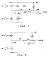
- FIG. 5 shows an auto-sleep detect circuit of the present disclosure supporting sleep operation.
- the output In sleep mode the output is tri-stated if the current in the coil reaches zero. This can provide a very high efficiency mode for low loads, a third switch SW3 is needed in this case.
- the third switch SW3 connects the sample point to the supply voltage whenever the output is tri-state.
- Switch SW1 is ON when PMOS transistor P1 is ON
- switch SW3 is ON when neither PMOS transistor P1 nor NMOS transistor N1 are ON
- switch SW2 is ON when NMOS transistor N1 is ON.
- Fig. 6 depicts a circuit disclosed for analog measurement of switching signals allowing the average current signal to be measured directly. In this case the value of the average current is not being measured against a reference, so the "fill-in” voltage is not known. Instead it is proposed to "fill-in” the unknown portion of the signal by using the average of the preceding period. This can be done by feeding back the average current signal back to the sample point during the off-time via switch SW4 of Fig. 6 during off-time
- the circuit essentially works similar as a sample and hold, except that the value to be held is first filtered. This means that the circuit does not simply sample the last value before the switch SW1 turns off (which would give peak sampling and add back duty-cycle dependence) but instead holds the average value of the signal during the on-times of the preceding cycles. Again, the value during the off-time is not added, and so does not distort the averaged signal.
- the output signal at the port SLP-DEM thus represents a true measurement of the coil current and allows a correct control of PFM, PWM and sleep modes independently of the duty cycle in any range of the current.
- the output signal can also be used for any other further processing because it presents a true measurement of the pulsed current through the pass transistor.
- Fig. 7 shows a method to measure a pulsed output current of a pass transistor of a switching circuit in order to detect, independently of a duty cycle of the switching circuit, if the current through the pass transistor has reached one or more threshold values.
- a first step 70 depicts a provision of a switching circuit comprising a pass transistor, a reference voltage and an arrangement of switches.
- the next step 71 shows comparing the reference voltage with a voltage representing the pulsed current through the pass transistor while the pass transistor is ON, plus a voltage suitably filling-in a remaining part of a cycle of the switching circuit while the pass transistor is OFF, wherein the comparison detects independently of the duty cycle if the current through the pass transistor has reached one or more threshold values.
- Fig. 8 shows a method to measure a pulsed output current of a pass transistor of a switching circuit independently of a duty cycle of the switching circuit.
- a first step 80 depicts a provision of a switching circuit comprising a pass transistor and an arrangement of switches.
- the next step 81 shows measuring the current through the pass transistor during an ON-time of the pass transistor, wherein an average current measurement of the previous period is filled-in during OFF-time of the pass transistor.
Landscapes
- Physics & Mathematics (AREA)
- General Physics & Mathematics (AREA)
- Engineering & Computer Science (AREA)
- Power Engineering (AREA)
- Dc-Dc Converters (AREA)
Abstract

Description
- The present document relates to switching DC-to-DC converters. In particular, the present document relates to electronic circuits and methods to distinguish correctly between a low quiescent operation mode and a high output current operation mode.
- In switching DC-to-DC converters, such as e.g. buck converters, an auto-sleep function decides whether the switching converter should be operating in a low output current/low quiescent mode (in buck converters known to the inventors this is referred to as PFM mode) or a high output current/high quiescent mode (PWM mode).
- The low current mode is very efficient but cannot handle high load currents. The high current mode gives good load transient performance, but with high quiescent currents.
- The buck converter therefore automatically switches between modes. This is performed by measuring output current and deciding which mode would give higher efficiency.
- The buck converter measures in prior art the output current by measuring the voltage drop across the PMOS pass-device. This voltage drop is very small, but is proportional to the current in the PMOS pass device while it is on. Of course, the PMOS pass device is not switched on all the time, and for some parts of a cycle it will be switched off. At this point the switching node goes low and, if the voltage across the PMOS pass device is still measured, it would correspond to a very large, and false, output current.
- Measuring another voltage than the voltage drop of the PMOS pass device is not practical in most buck converter or other converter architectures.
- A further principal object of the disclosure is to distinguish correctly and fast between low quiescent operation mode and a high output current operation mode of switching circuits independently of duty cycle variations...
- A further principal object of the disclosure is to distinguish correctly and fast between low quiescent operation mode and a high output current operation mode of switching circuits independently of duty cycle variations covering also sleep mode operation...
- A further object of the disclosure is to achieve a method and a circuit thereof which measures a pulsed current for only part of a cycle, and assumes a value for the remaining part of the cycle.
- A further object of the disclosure is to achieve a circuit that compares the average of the measured voltage to a reference voltage and samples then the same reference voltage as is used for the comparison for the remaining part of the cycle.
- In accordance with the objects of this disclosure a circuit configured to measure a pulsed current through a pass transistor of a switching circuit in order to detect, independently of a duty cycle of the switching circuit, if the current through the pass transistor has reached one or more threshold values has been achieved. The circuit disclosed comprises a pass transistor connected between a supply voltage and a load of the pass transistor, a node for a reference voltage, and a circuit capable of comparing the reference voltage with a voltage representing the pulsed current through the pass transistor while the pass transistor is ON, including suitably filling-in a voltage to a remaining part of a cycle of the switching circuit while the pass transistor is OFF, wherein the comparison detects independently of the duty cycle if the current through the pass transistor has reached one or more threshold values.
- In accordance with the objects of this disclosure a circuit configured to measure a pulsed current through a pass transistor of a switching circuit in order to detect, independently of a duty cycle of the switching circuit, if the current through the pass transistor has reached one or more threshold values has been achieved. The circuit disclosed firstly comprises: a pass transistor connected between a supply voltage and a load of the pass transistor, a sense transistor connected between the supply voltage and a current source, wherein a node for a reference voltage is deployed between the sense transistor and the current source and wherein the node for the reference voltage is connected to a second terminal of a second switch and to a second input of a comparator, wherein the sense transistor is matched to the pass transistor, and said current source connected between ground and said sense transistor. Furthermore the circuit comprises a first switch wherein a first terminal of the switch is connected to the load of the pass transistor and a second terminal of the switch is connected to a first input of the comparator and to a first terminal of the second switch, said second switch; and said comparator wherein its output is used to detect if the current through the pass transistor has reached a threshold; wherein the first switch is closed and the second switch is open during ON-time of the pass transistor and vice versa the first switch is open and the second switch is closed during OFF-time of the comparator.
- In accordance with the objects of this disclosure a method to measure a pulsed current through a pass transistor of a switching circuit in order to detect, independently of a duty cycle of the switching circuit, if the current through the pass transistor has reached a threshold value has been achieved. The method disclosed comprises the steps of:(1) providing a switching circuit comprising a pass transistor, a reference voltage and an arrangement of two switches, and (2) comparing the reference voltage with a voltage representing the pulsed current through the pass transistor while the pass transistor is ON, plus a voltage suitably filling-in a remaining part of a cycle of the switching circuit while the pass transistor is OFF, wherein the comparison detects independently of the duty cycle if the current through the pass transistor has reached one or more threshold values.
- In accordance with the objects of this disclosure a method to measure a pulsed current through a pass transistor of a switching circuit independently of a duty cycle of the switching circuit has been achieved. The method disclosed comprises the steps of (1) providing a switching circuit comprising a pass transistor and an arrangement of switches, and (2) measuring the current through the pass transistor during an ON-time of the pass transistor wherein during OFF-time of the pass transistor an average current measurement of the previous period is filled-in.
- The invention is explained below in an exemplary manner with reference to the accompanying drawings, wherein
-
Fig. 1 prior art shows an auto-sleep detect circuit. -
Fig. 2 prior art illustrates auto-sleep detect operation. -
Fig. 3a shows a PMOS pass transistor being connected in a configuration having a common gate and source potential with a "dummy output device" P2, wherein a current source Iref generates a current through P2. -
Fig. 3b shows that alternatively an NMOS pass device is connected to a dummy NMOS device wherein a current source generates a current through the dummy NMOS device. -
Fig. 4 shows how the auto sleep detect circuit ofFig. 3 operates. -
Fig. 5 shows an auto-sleep detect circuit of the present disclosure supporting sleep operation. -
Fig. 6 depicts a circuit disclosed for analog measurement of switching signals. -
Fig. 7 shows a flowchart of a method to measure a pulsed output current of a pass transistor of a switching circuit in order to detect, independently of a duty cycle. -
Fig. 8 shows a flowchart of a method to measure a pulsed output current of a pass transistor of a switching circuit independently of a duty cycle of the switching circuit. - Methods and circuits to control a switching DC-to-DC-converter is in sleep operation mode, i.e. pulse-frequency modulation (PFM) mode or in high-output current operation mode, i.e. pulse width modulation (PWM) mode to ensure that the converter operates in a mode with the highest efficiency according to an actual load situation.
- It should be understood that the disclosure can be applied to any circuit providing a continuous triangle wave signal wherein only half of the triangle wave can be monitored. An average value of the half wave, which can't be monitored, must be the same average value as the average value of the half wave signal which is monitored.
- In a preferred embodiment of the invention a buck DC-to-DC converter is described. It should be noted that the methods and circuits disclosed can be applied to any switched mode converters to ensure maximum efficiency in spite of a wide range of duty cycles.
- An auto-sleep function averages an output current of a switching converter over several cycles to determine what the average output current is. If this is high, then the buck moves to sync mode (PWM) if it is low, then it moves to sleep mode (PFM).
-
Fig. 1 prior art shows an auto sleep detect circuit. The pass-devices are formed by the transistors P1 and N1. The switching voltage LX is output to an inductor and a capacitor (not shown) to smooth the voltage. The LX voltage is also sensed by the switch SW1 which is closed when the PMOS P1 is on. The main pass-device P1 has a sense device P2 which is well matched to P1. This device P2 is biased with the reference current Iref to generate a voltage Vref with respect to supply voltage VDD. The sampled sense voltage is filtered by resistor R1 and capacitor C1 and compared to the reference voltage Vref by the comparator 12. - Generally, if the average voltage on node LX, when the PMOS P1 is on, is lower than Vref then it is an indication that the output current is high and the buck should be operating in PWM mode.
- However, when the PMOS P1 is off, the LX node goes low to almost the ground voltage. This must not be included in the averaged voltage signal, as it would equate to a very large current through the PMOS P1 transistor. The sampling circuit of
Fig. 1 prior art samples instead the supply voltage VDD, which is logically equal to the no-current voltage. This is done by opening switch SW1 and closing switch SW2. - The operation of the circuit of
Fig. 1 prior art is shown inFig. 2 prior art. The reference voltage Vref is created by passing the reference current IREF through the dummy output device P2.Fig. 2 prior art shows in the top diagram a load current Iload of the buck converter, in the middle diagram Vsample and Vfilt, which has been smoothed by the RC filter R1/C1. And in the bottom diagram a constant reference voltage Vref is shown. The dotted line Vfilt again, thecomparator 10 switches when Vref equals Vfilt. - In order to calculate the correct current for the reference current IREF the following analysis can be performed:

and, if D is the duty cycle and T is the period: - T x Vaverage = Ton x VLX + Toff x VDD where
- Ton = D x T and Toff = (1-D) x T so
- Vaverage = D x VLX + (1-D) X VDD, which reduces to
- Vaverage = VDD - D x Ron x Ion
- Now the
comparator 10 will switch when - Vaverage = Vref which reduces to
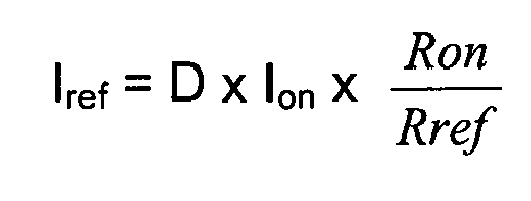
- It should be obvious now that the circuit is dependent upon duty cycle and so the threshold can't accurately be calculated in the presence of duty cycle D variations.
- For e.g. buck converters with a large range of output and input volt the duty cycle can vary by a large amount. This, in turn, causes a very large variation in auto-sleep threshold currents.
-
Fig. 3 illustrates one embodiment of an auto-sleep detect circuit of the present disclosure. The auto-sleep detect block ofFig. 3 controls whether the buck converter is in PFM or PWM mode. The block primarily measures the average current in the output to determine whether sleep or sync mode would be more efficient. The block also monitors the buck in sleep to detect fast load transients that would require sync mode to follow. - The average current is monitored by measuring the current in the PMOS, sampling this value and then filtering the result by the RC-Filter comprising resistor R1 and capacitor C1.
- In order to make the circuit non duty-cycle dependent the sample circuit of
Fig. 3 must switch between node LX and the reference voltage Vref itself, i.e. during the ON-phase of PMOS transistor P1 switch SW1 is closed and switch SW2 is open, while during the OFF-period of transistor P1 switch SW1 is open and switch SW2 is closed - The analysis of the circuit is as follows:


- Now the comparator will switch when
Vaverage = Vref which reduces to
wherein resistance Rref corresponds to the ON-resistance of transistor P2 shown inFig. 3 . - The reference current Iref has no duty-cycle (D) term, confirming Iref is fixed and not duty cycle dependent. Thus the circuit of
Fig. 3 measures exactly the current through the PMOS transistor.at any time and circumstances. This is graphically demonstrated inFig. 4 illustrating how the auto-sleep detect circuit ofFig. 3 operates.Fig. 4 shows clearly that when the load current is low the sampling effect makes the average signal too high. When the load current is high the sampling effect makes the average signal too low. But, when the PMOS current is at the threshold value, the sampling effect has no effect on the signal value. -
Fig. 3a shows a PMOS pass transistor being connected in a configuration having a common gate and source potential with a "dummy output device" P2, wherein a current source Iref generates a current through P2. -
Fig. 3b shows that alternatively an NMOS pass device could be used that is connected to a dummy NMOS device wherein a current source generates a current through the dummy NMOS device. - It should be noted that Vfilt, as shown in
Fig. 4 corresponds to Vaverage after filtering by the RC filter comprising R1 and C1. Additionally a hysteretic function is provided to prevent any toggling between operation modes. - A key extension of the circuit is to cover sleep mode operation.
Fig. 5 shows an auto-sleep detect circuit of the present disclosure supporting sleep operation. In sleep mode the output is tri-stated if the current in the coil reaches zero. This can provide a very high efficiency mode for low loads, a third switch SW3 is needed in this case. The third switch SW3 connects the sample point to the supply voltage whenever the output is tri-state. Switch SW1 is ON when PMOS transistor P1 is ON, switch SW3 is ON when neither PMOS transistor P1 nor NMOS transistor N1 are ON, and switch SW2 is ON when NMOS transistor N1 is ON. - Alternately, in sleep mode, when NMOS transistor N1 is ON, all three switches SW1, SW2, and SW3 are open achieving a tri-state mode.
- A related variation of the circuit supporting sleep operation of the present disclosure is illustrated in
Fig. 6. Fig. 6 depicts a circuit disclosed for analog measurement of switching signals allowing the average current signal to be measured directly. In this case the value of the average current is not being measured against a reference, so the "fill-in" voltage is not known. Instead it is proposed to "fill-in" the unknown portion of the signal by using the average of the preceding period. This can be done by feeding back the average current signal back to the sample point during the off-time via switch SW4 ofFig. 6 during off-time - In this case the circuit essentially works similar as a sample and hold, except that the value to be held is first filtered. This means that the circuit does not simply sample the last value before the switch SW1 turns off (which would give peak sampling and add back duty-cycle dependence) but instead holds the average value of the signal during the on-times of the preceding cycles. Again, the value during the off-time is not added, and so does not distort the averaged signal.
- The output signal at the port SLP-DEM thus represents a true measurement of the coil current and allows a correct control of PFM, PWM and sleep modes independently of the duty cycle in any range of the current. The output signal can also be used for any other further processing because it presents a true measurement of the pulsed current through the pass transistor.
-
Fig. 7 shows a method to measure a pulsed output current of a pass transistor of a switching circuit in order to detect, independently of a duty cycle of the switching circuit, if the current through the pass transistor has reached one or more threshold values. - A
first step 70 depicts a provision of a switching circuit comprising a pass transistor, a reference voltage and an arrangement of switches. Thenext step 71 shows comparing the reference voltage with a voltage representing the pulsed current through the pass transistor while the pass transistor is ON, plus a voltage suitably filling-in a remaining part of a cycle of the switching circuit while the pass transistor is OFF, wherein the comparison detects independently of the duty cycle if the current through the pass transistor has reached one or more threshold values. -
Fig. 8 shows a method to measure a pulsed output current of a pass transistor of a switching circuit independently of a duty cycle of the switching circuit. - A
first step 80 depicts a provision of a switching circuit comprising a pass transistor and an arrangement of switches. Thenext step 81 shows measuring the current through the pass transistor during an ON-time of the pass transistor, wherein an average current measurement of the previous period is filled-in during OFF-time of the pass transistor. - While the invention has been particularly shown and described with reference to the preferred embodiments thereof, it will be understood by those skilled in the art that various changes in form and details may be made without departing from the spirit and scope of the invention.
Claims (26)
- A circuit configured to measure a pulsed current through a pass transistor of a switching circuit in order to detect, independently of a duty cycle of the switching circuit, if the current through the pass transistor has reached a threshold value, comprising:- a pass transistor connected between a supply voltage and a load of the pass transistor;- a node for a reference voltage; and- a circuit capable of comparing the reference voltage with a voltage representing the pulsed current through the pass transistor while the pass transistor is ON, including suitably filling-in a voltage to a remaining part of a cycle of the switching circuit while the pass transistor is OFF, wherein the comparison detects independently of the duty cycle if the current through the pass transistor has reached one or more threshold values.
- A circuit configured to measure a pulsed current through a pass transistor of a switching circuit in order to detect, independently of a duty cycle of the switching circuit, if the current through the pass transistor has reached a threshold value, comprising:- a pass transistor connected between a supply voltage and a load of the pass transistor;- a sense transistor connected between the supply voltage and a current source wherein a node for a reference voltage is deployed between the sense transistor and the current source and wherein the node for the reference voltage is connected to a second terminal of a second switch and to a second input of a comparator, wherein the sense transistor is matched to the pass transistor;- said current source connected between ground and said sense transistor;- a first switch wherein a first terminal of the switch is connected to the load of the pass transistor and a second terminal of the switch is connected to a first input of the comparator and to a first terminal of the second switch;- said second switch; and- said comparator wherein its output is used to detect if the current through the pass transistor has reached a threshold;wherein the first switch is closed and the second switch is open during ON-time of the pass transistor and vice versa the first switch is open and the second switch is closed during OFF-time of the comparator.
- The circuit of claim 1 or 2 wherein a resistive-capacitive filter is deployed at the first input of the comparator in order to smooth the input of the comparator.
- The circuit of claim 1 or 2 wherein said pass transistor is a PMOS device or a NMOS device.
- The circuit of claim 1 or 2 wherein the switching circuit is further comprising a second pass transistor, which is an NMOS device or a PMOS device.
- The circuit of claim 1 or 2 wherein the switching circuit is a DC-to-DC converter and the load is a coil.
- The circuit of claim 6 wherein the DC-to-DC converter is a buck converter.
- The circuit of claim 6, wherein one threshold is used to control either pulse-frequency modulation mode or pulse-width modulation mode of the DC-to-DC converter.
- The circuit of claim 1 or 2, wherein the sense transistor is replaced by a resistor.
- The circuit of claim 1 or 2, wherein a third switch is deployed between supply voltage and the second terminal of the first switch in order to control either pulse-frequency modulation mode, pulse-width modulation mode, or sleep operation mode of the DC-to-DC converter.
- A method to measure a pulsed current through a pass transistor of a switching circuit in order to detect, independently of a duty cycle of the switching circuit, if the current through the pass transistor has reached one or more threshold values, the method comprising the steps of:(1) providing a switching circuit comprising a pass transistor, a reference voltage and an arrangement of two switches; and(2) comparing the reference voltage with a voltage representing the pulsed current through the pass transistor while the pass transistor is ON, plus a voltage equal to the reference voltage suitably filling-in a remaining part of a cycle of the switching circuit while the pass transistor is OFF, wherein the comparison detects independently of the duty cycle if the current through the pass transistor has reached one or more threshold values.
- The method of claim 26, wherein the switching circuit is a buck converter, and wherein a threshold value controls if the buck converter operates in pulse-frequency modulation mode or in pulse- width modulation mode.
- The method of claim 12, wherein a first input of a comparator is connected to a node between the pass transistor and a first terminal of a coil of the buck converter during ON-time of the pass transistor and the first input of the comparator is connected to the reference voltage during OFF-time of the pass transistor wherein a second input of the comparator is constantly connected to the reference voltage.
- The method of claim 12, wherein the first input of the comparator is filtered by a RC-filter.
- The method of claim 11, wherein the switching circuit is a switching DC to DC converter and wherein by adding a third switch between supply voltage and an input of a comparator the DC-to-DC converter is configured to be controlled in pulse-frequency modulation mode, in pulse- width modulation mode, or in sleep mode..
- The method of claim 15, wherein during PFM or PWM mode a first input of a comparator is connected to a node between the pass transistor and a first terminal of a coil of the buck converter during ON-time of the pass transistor and the first input of the comparator is connected to the reference voltage during OFF-time of the pass transistor wherein a second input of the comparator is constantly connected to the reference voltage while during sleep mode the first input of the comparator is connected to supply voltage when the pass transistor is OFF.
- The method of claim 16, wherein the first input of the comparator is filtered by a RC-filter.
- The method of claim 11, wherein the reference voltage is generated by a voltage drop of a sense transistor caused by a reference current generated by a current source wherein a gate of the sense transistor is connected to a gate of the pass transistor.
- The method of claim 18, wherein the reference current is defined by Iref = Ion x Ron/Rref, wherein Ion is the current through the pass transistor during ON-time, Ron is an ON-resistance of the pass transistor, and Rref is the ON-resistance of the sense transistor.
- The method of claim 11 wherein the reference voltage is generated by a voltage drop of a sense resistor caused by a reference current generated by a current source.
- A method to measure a pulsed current through a pass transistor of a switching circuit independently of a duty cycle of the switching circuit, the method comprising the steps of:(1) providing a switching circuit comprising a pass transistor and an arrangement of switches; and(2) measuring the current through the pass transistor during an ON-time of the pass transistor wherein during OFF-time of the pass transistor an average current measurement of the previous period is filled-in.
- The method of claim 21, wherein the fill-in of the average current measurement is performed by feeding back a current average measurement back to a sample point during an OFF-period to be used for filling-in in the next period.
- The method of claim 11 or 21, wherein said pass transistor is a PMOS device.
- The method of claim 11 or 21, wherein the switching circuit is further comprising a second pass transistor, which is an NMOS device.
- The method of claim 11 or 21, wherein the switching circuit is a DC-to-DC converter.
- The method of claim 25, wherein the DC-to-DC converter is a buck converter.
Priority Applications (2)
| Application Number | Priority Date | Filing Date | Title |
|---|---|---|---|
| EP14392004.9A EP2933645B1 (en) | 2014-04-16 | 2014-04-16 | Duty cycle independent comparator |
| US14/262,995 US9739810B2 (en) | 2014-04-16 | 2014-04-28 | Duty cycle independent comparator |
Applications Claiming Priority (1)
| Application Number | Priority Date | Filing Date | Title |
|---|---|---|---|
| EP14392004.9A EP2933645B1 (en) | 2014-04-16 | 2014-04-16 | Duty cycle independent comparator |
Publications (2)
| Publication Number | Publication Date |
|---|---|
| EP2933645A1 true EP2933645A1 (en) | 2015-10-21 |
| EP2933645B1 EP2933645B1 (en) | 2020-02-12 |
Family
ID=50732081
Family Applications (1)
| Application Number | Title | Priority Date | Filing Date |
|---|---|---|---|
| EP14392004.9A Active EP2933645B1 (en) | 2014-04-16 | 2014-04-16 | Duty cycle independent comparator |
Country Status (2)
| Country | Link |
|---|---|
| US (1) | US9739810B2 (en) |
| EP (1) | EP2933645B1 (en) |
Cited By (1)
| Publication number | Priority date | Publication date | Assignee | Title |
|---|---|---|---|---|
| CN110031671A (en) * | 2019-05-16 | 2019-07-19 | 上海东软载波微电子有限公司 | Drive over-current detection circuit |
Families Citing this family (8)
| Publication number | Priority date | Publication date | Assignee | Title |
|---|---|---|---|---|
| US9548651B2 (en) * | 2013-02-22 | 2017-01-17 | Texas Instruments Incorporated | Advanced control circuit for switched-mode DC-DC converter |
| TWI545901B (en) * | 2014-06-23 | 2016-08-11 | 瑞鼎科技股份有限公司 | Comparator control circuit |
| CN106330143B (en) * | 2016-08-30 | 2019-03-12 | 灿芯半导体(上海)有限公司 | Duty-ratio calibrating circuit |
| US10958174B1 (en) * | 2019-07-08 | 2021-03-23 | Dialog Semiconductor Inc. | Light load detector circuit for inductive DC-DC converter |
| US20220341973A1 (en) * | 2021-04-21 | 2022-10-27 | Cirrus Logic International Semiconductor Ltd. | Temperature-insensitive current sensing for power stage |
| US12438463B2 (en) | 2022-05-19 | 2025-10-07 | Stmicroelectronics S.R.L. | Method and apparatus for sensing inductor input/output current in a DC-DC converter circuit |
| US12003177B2 (en) | 2022-05-19 | 2024-06-04 | Stmicroelectronics S.R.L. | Method and apparatus for sensing output current in a DC-DC converter circuit |
| US12413131B2 (en) | 2022-05-19 | 2025-09-09 | Stmicroelectronics S.R.L. | Method and apparatus for sensing inductor input/output current in a DC-DC converter circuit |
Citations (3)
| Publication number | Priority date | Publication date | Assignee | Title |
|---|---|---|---|---|
| US5689162A (en) * | 1995-06-07 | 1997-11-18 | Sgs-Thomson Microelectronics, Inc. | Apparatus and method for current sensing for motor driver in pwm mode |
| US6479975B1 (en) * | 2001-09-26 | 2002-11-12 | Dialog Semicon | MOS current sense circuit |
| US20100289473A1 (en) * | 2009-05-12 | 2010-11-18 | Takuya Ishii | Current sense circuit and switching regulator using the same |
Family Cites Families (6)
| Publication number | Priority date | Publication date | Assignee | Title |
|---|---|---|---|---|
| US6495995B2 (en) * | 2001-03-09 | 2002-12-17 | Semtech Corporation | Self-clocking multiphase power supply controller |
| US7432695B2 (en) | 2005-04-18 | 2008-10-07 | Linear Technology Corporation | Adaptive power control for hysteretic regulators |
| US7518351B2 (en) | 2005-05-18 | 2009-04-14 | Linear Technology Corporation | Switching regulator over voltage reduction circuit and method |
| US7928705B2 (en) | 2008-03-12 | 2011-04-19 | Sony Ericsson Mobile Communications Ab | Switched mode voltage converter with low-current mode and methods of performing voltage conversion with low-current mode |
| US9246390B2 (en) * | 2008-04-16 | 2016-01-26 | Enpirion, Inc. | Power converter with controller operable in selected modes of operation |
| US8917067B2 (en) * | 2010-03-24 | 2014-12-23 | R2 Semiconductor, Inc. | Assisting an output current of a voltage converter |
-
2014
- 2014-04-16 EP EP14392004.9A patent/EP2933645B1/en active Active
- 2014-04-28 US US14/262,995 patent/US9739810B2/en active Active
Patent Citations (3)
| Publication number | Priority date | Publication date | Assignee | Title |
|---|---|---|---|---|
| US5689162A (en) * | 1995-06-07 | 1997-11-18 | Sgs-Thomson Microelectronics, Inc. | Apparatus and method for current sensing for motor driver in pwm mode |
| US6479975B1 (en) * | 2001-09-26 | 2002-11-12 | Dialog Semicon | MOS current sense circuit |
| US20100289473A1 (en) * | 2009-05-12 | 2010-11-18 | Takuya Ishii | Current sense circuit and switching regulator using the same |
Cited By (2)
| Publication number | Priority date | Publication date | Assignee | Title |
|---|---|---|---|---|
| CN110031671A (en) * | 2019-05-16 | 2019-07-19 | 上海东软载波微电子有限公司 | Drive over-current detection circuit |
| CN110031671B (en) * | 2019-05-16 | 2021-08-17 | 上海东软载波微电子有限公司 | Drive overcurrent detection circuit |
Also Published As
| Publication number | Publication date |
|---|---|
| US20150301091A1 (en) | 2015-10-22 |
| EP2933645B1 (en) | 2020-02-12 |
| US9739810B2 (en) | 2017-08-22 |
Similar Documents
| Publication | Publication Date | Title |
|---|---|---|
| EP2933645B1 (en) | Duty cycle independent comparator | |
| US9543838B2 (en) | Phase fault detection in switching power converters | |
| US7868483B2 (en) | Power management systems with current sensors | |
| CN106849650B (en) | Method and system for reducing transients in DC-DC converters | |
| US9685868B2 (en) | Synchronous rectifier for buck converter without the need for a comparator | |
| US7372240B2 (en) | Output load adaptable MOSFET gate drive voltage level in a DC-DC controller | |
| US20100253296A1 (en) | Symmetric sample and hold over-current sensing method and apparatus | |
| KR101193669B1 (en) | System and method for determining load current in switching regulators | |
| CN111628628B (en) | Synchronous boost regulator circuit with pass-through operation control | |
| US9450487B2 (en) | DC to DC converter | |
| US10243344B2 (en) | Semiconductor device | |
| US7498784B2 (en) | Average current detector circuit | |
| JPH06311734A (en) | Output short circuit protection circuit | |
| EP3002860B1 (en) | Peak-buck peak-boost current-mode control for switched step-up step-down regulators | |
| US12413131B2 (en) | Method and apparatus for sensing inductor input/output current in a DC-DC converter circuit | |
| CN101656465B (en) | Control circuit, power converter and control method | |
| CN115664204B (en) | Switching power supply circuit, power supply device and switching power supply control method | |
| US9306455B2 (en) | Hysteretic power converter with switch gate current sense | |
| US9634569B1 (en) | DC-to-DC output current sensing | |
| US10224800B2 (en) | Load current detection techniques for discontinuous conduction mode | |
| US10958174B1 (en) | Light load detector circuit for inductive DC-DC converter | |
| CN120110144A (en) | Power converter with current limiting protection mechanism | |
| KR101654785B1 (en) | Buck-converter bcm control apparatus and method thereof | |
| EP3503395A1 (en) | Current detector for bidirectional switching power supply | |
| US12003177B2 (en) | Method and apparatus for sensing output current in a DC-DC converter circuit |
Legal Events
| Date | Code | Title | Description |
|---|---|---|---|
| PUAI | Public reference made under article 153(3) epc to a published international application that has entered the european phase |
Free format text: ORIGINAL CODE: 0009012 |
|
| AK | Designated contracting states |
Kind code of ref document: A1 Designated state(s): AL AT BE BG CH CY CZ DE DK EE ES FI FR GB GR HR HU IE IS IT LI LT LU LV MC MK MT NL NO PL PT RO RS SE SI SK SM TR |
|
| AX | Request for extension of the european patent |
Extension state: BA ME |
|
| RAP1 | Party data changed (applicant data changed or rights of an application transferred) |
Owner name: DIALOG SEMICONDUCTOR (UK) LIMITED |
|
| 17P | Request for examination filed |
Effective date: 20160324 |
|
| RBV | Designated contracting states (corrected) |
Designated state(s): AL AT BE BG CH CY CZ DE DK EE ES FI FR GB GR HR HU IE IS IT LI LT LU LV MC MK MT NL NO PL PT RO RS SE SI SK SM TR |
|
| STAA | Information on the status of an ep patent application or granted ep patent |
Free format text: STATUS: EXAMINATION IS IN PROGRESS |
|
| 17Q | First examination report despatched |
Effective date: 20171214 |
|
| GRAP | Despatch of communication of intention to grant a patent |
Free format text: ORIGINAL CODE: EPIDOSNIGR1 |
|
| STAA | Information on the status of an ep patent application or granted ep patent |
Free format text: STATUS: GRANT OF PATENT IS INTENDED |
|
| INTG | Intention to grant announced |
Effective date: 20191104 |
|
| GRAS | Grant fee paid |
Free format text: ORIGINAL CODE: EPIDOSNIGR3 |
|
| GRAA | (expected) grant |
Free format text: ORIGINAL CODE: 0009210 |
|
| STAA | Information on the status of an ep patent application or granted ep patent |
Free format text: STATUS: THE PATENT HAS BEEN GRANTED |
|
| AK | Designated contracting states |
Kind code of ref document: B1 Designated state(s): AL AT BE BG CH CY CZ DE DK EE ES FI FR GB GR HR HU IE IS IT LI LT LU LV MC MK MT NL NO PL PT RO RS SE SI SK SM TR |
|
| REG | Reference to a national code |
Ref country code: GB Ref legal event code: FG4D |
|
| REG | Reference to a national code |
Ref country code: CH Ref legal event code: EP |
|
| REG | Reference to a national code |
Ref country code: AT Ref legal event code: REF Ref document number: 1232852 Country of ref document: AT Kind code of ref document: T Effective date: 20200215 |
|
| REG | Reference to a national code |
Ref country code: IE Ref legal event code: FG4D |
|
| REG | Reference to a national code |
Ref country code: DE Ref legal event code: R096 Ref document number: 602014060835 Country of ref document: DE |
|
| PG25 | Lapsed in a contracting state [announced via postgrant information from national office to epo] |
Ref country code: RS Free format text: LAPSE BECAUSE OF FAILURE TO SUBMIT A TRANSLATION OF THE DESCRIPTION OR TO PAY THE FEE WITHIN THE PRESCRIBED TIME-LIMIT Effective date: 20200212 Ref country code: FI Free format text: LAPSE BECAUSE OF FAILURE TO SUBMIT A TRANSLATION OF THE DESCRIPTION OR TO PAY THE FEE WITHIN THE PRESCRIBED TIME-LIMIT Effective date: 20200212 Ref country code: NO Free format text: LAPSE BECAUSE OF FAILURE TO SUBMIT A TRANSLATION OF THE DESCRIPTION OR TO PAY THE FEE WITHIN THE PRESCRIBED TIME-LIMIT Effective date: 20200512 |
|
| REG | Reference to a national code |
Ref country code: LT Ref legal event code: MG4D |
|
| REG | Reference to a national code |
Ref country code: NL Ref legal event code: MP Effective date: 20200212 |
|
| PG25 | Lapsed in a contracting state [announced via postgrant information from national office to epo] |
Ref country code: LV Free format text: LAPSE BECAUSE OF FAILURE TO SUBMIT A TRANSLATION OF THE DESCRIPTION OR TO PAY THE FEE WITHIN THE PRESCRIBED TIME-LIMIT Effective date: 20200212 Ref country code: SE Free format text: LAPSE BECAUSE OF FAILURE TO SUBMIT A TRANSLATION OF THE DESCRIPTION OR TO PAY THE FEE WITHIN THE PRESCRIBED TIME-LIMIT Effective date: 20200212 Ref country code: BG Free format text: LAPSE BECAUSE OF FAILURE TO SUBMIT A TRANSLATION OF THE DESCRIPTION OR TO PAY THE FEE WITHIN THE PRESCRIBED TIME-LIMIT Effective date: 20200512 Ref country code: IS Free format text: LAPSE BECAUSE OF FAILURE TO SUBMIT A TRANSLATION OF THE DESCRIPTION OR TO PAY THE FEE WITHIN THE PRESCRIBED TIME-LIMIT Effective date: 20200612 Ref country code: GR Free format text: LAPSE BECAUSE OF FAILURE TO SUBMIT A TRANSLATION OF THE DESCRIPTION OR TO PAY THE FEE WITHIN THE PRESCRIBED TIME-LIMIT Effective date: 20200513 Ref country code: HR Free format text: LAPSE BECAUSE OF FAILURE TO SUBMIT A TRANSLATION OF THE DESCRIPTION OR TO PAY THE FEE WITHIN THE PRESCRIBED TIME-LIMIT Effective date: 20200212 |
|
| PG25 | Lapsed in a contracting state [announced via postgrant information from national office to epo] |
Ref country code: NL Free format text: LAPSE BECAUSE OF FAILURE TO SUBMIT A TRANSLATION OF THE DESCRIPTION OR TO PAY THE FEE WITHIN THE PRESCRIBED TIME-LIMIT Effective date: 20200212 |
|
| PG25 | Lapsed in a contracting state [announced via postgrant information from national office to epo] |
Ref country code: LT Free format text: LAPSE BECAUSE OF FAILURE TO SUBMIT A TRANSLATION OF THE DESCRIPTION OR TO PAY THE FEE WITHIN THE PRESCRIBED TIME-LIMIT Effective date: 20200212 Ref country code: CZ Free format text: LAPSE BECAUSE OF FAILURE TO SUBMIT A TRANSLATION OF THE DESCRIPTION OR TO PAY THE FEE WITHIN THE PRESCRIBED TIME-LIMIT Effective date: 20200212 Ref country code: ES Free format text: LAPSE BECAUSE OF FAILURE TO SUBMIT A TRANSLATION OF THE DESCRIPTION OR TO PAY THE FEE WITHIN THE PRESCRIBED TIME-LIMIT Effective date: 20200212 Ref country code: PT Free format text: LAPSE BECAUSE OF FAILURE TO SUBMIT A TRANSLATION OF THE DESCRIPTION OR TO PAY THE FEE WITHIN THE PRESCRIBED TIME-LIMIT Effective date: 20200705 Ref country code: SK Free format text: LAPSE BECAUSE OF FAILURE TO SUBMIT A TRANSLATION OF THE DESCRIPTION OR TO PAY THE FEE WITHIN THE PRESCRIBED TIME-LIMIT Effective date: 20200212 Ref country code: RO Free format text: LAPSE BECAUSE OF FAILURE TO SUBMIT A TRANSLATION OF THE DESCRIPTION OR TO PAY THE FEE WITHIN THE PRESCRIBED TIME-LIMIT Effective date: 20200212 Ref country code: EE Free format text: LAPSE BECAUSE OF FAILURE TO SUBMIT A TRANSLATION OF THE DESCRIPTION OR TO PAY THE FEE WITHIN THE PRESCRIBED TIME-LIMIT Effective date: 20200212 Ref country code: SM Free format text: LAPSE BECAUSE OF FAILURE TO SUBMIT A TRANSLATION OF THE DESCRIPTION OR TO PAY THE FEE WITHIN THE PRESCRIBED TIME-LIMIT Effective date: 20200212 Ref country code: DK Free format text: LAPSE BECAUSE OF FAILURE TO SUBMIT A TRANSLATION OF THE DESCRIPTION OR TO PAY THE FEE WITHIN THE PRESCRIBED TIME-LIMIT Effective date: 20200212 |
|
| REG | Reference to a national code |
Ref country code: DE Ref legal event code: R097 Ref document number: 602014060835 Country of ref document: DE |
|
| REG | Reference to a national code |
Ref country code: AT Ref legal event code: MK05 Ref document number: 1232852 Country of ref document: AT Kind code of ref document: T Effective date: 20200212 |
|
| PG25 | Lapsed in a contracting state [announced via postgrant information from national office to epo] |
Ref country code: MC Free format text: LAPSE BECAUSE OF FAILURE TO SUBMIT A TRANSLATION OF THE DESCRIPTION OR TO PAY THE FEE WITHIN THE PRESCRIBED TIME-LIMIT Effective date: 20200212 |
|
| REG | Reference to a national code |
Ref country code: CH Ref legal event code: PL |
|
| PLBE | No opposition filed within time limit |
Free format text: ORIGINAL CODE: 0009261 |
|
| STAA | Information on the status of an ep patent application or granted ep patent |
Free format text: STATUS: NO OPPOSITION FILED WITHIN TIME LIMIT |
|
| 26N | No opposition filed |
Effective date: 20201113 |
|
| PG25 | Lapsed in a contracting state [announced via postgrant information from national office to epo] |
Ref country code: CH Free format text: LAPSE BECAUSE OF NON-PAYMENT OF DUE FEES Effective date: 20200430 Ref country code: LU Free format text: LAPSE BECAUSE OF NON-PAYMENT OF DUE FEES Effective date: 20200416 Ref country code: AT Free format text: LAPSE BECAUSE OF FAILURE TO SUBMIT A TRANSLATION OF THE DESCRIPTION OR TO PAY THE FEE WITHIN THE PRESCRIBED TIME-LIMIT Effective date: 20200212 Ref country code: IT Free format text: LAPSE BECAUSE OF FAILURE TO SUBMIT A TRANSLATION OF THE DESCRIPTION OR TO PAY THE FEE WITHIN THE PRESCRIBED TIME-LIMIT Effective date: 20200212 Ref country code: LI Free format text: LAPSE BECAUSE OF NON-PAYMENT OF DUE FEES Effective date: 20200430 Ref country code: FR Free format text: LAPSE BECAUSE OF NON-PAYMENT OF DUE FEES Effective date: 20200430 |
|
| REG | Reference to a national code |
Ref country code: BE Ref legal event code: MM Effective date: 20200430 |
|
| PG25 | Lapsed in a contracting state [announced via postgrant information from national office to epo] |
Ref country code: SI Free format text: LAPSE BECAUSE OF FAILURE TO SUBMIT A TRANSLATION OF THE DESCRIPTION OR TO PAY THE FEE WITHIN THE PRESCRIBED TIME-LIMIT Effective date: 20200212 Ref country code: BE Free format text: LAPSE BECAUSE OF NON-PAYMENT OF DUE FEES Effective date: 20200430 Ref country code: PL Free format text: LAPSE BECAUSE OF FAILURE TO SUBMIT A TRANSLATION OF THE DESCRIPTION OR TO PAY THE FEE WITHIN THE PRESCRIBED TIME-LIMIT Effective date: 20200212 |
|
| PG25 | Lapsed in a contracting state [announced via postgrant information from national office to epo] |
Ref country code: IE Free format text: LAPSE BECAUSE OF NON-PAYMENT OF DUE FEES Effective date: 20200416 |
|
| PG25 | Lapsed in a contracting state [announced via postgrant information from national office to epo] |
Ref country code: TR Free format text: LAPSE BECAUSE OF FAILURE TO SUBMIT A TRANSLATION OF THE DESCRIPTION OR TO PAY THE FEE WITHIN THE PRESCRIBED TIME-LIMIT Effective date: 20200212 Ref country code: MT Free format text: LAPSE BECAUSE OF FAILURE TO SUBMIT A TRANSLATION OF THE DESCRIPTION OR TO PAY THE FEE WITHIN THE PRESCRIBED TIME-LIMIT Effective date: 20200212 Ref country code: CY Free format text: LAPSE BECAUSE OF FAILURE TO SUBMIT A TRANSLATION OF THE DESCRIPTION OR TO PAY THE FEE WITHIN THE PRESCRIBED TIME-LIMIT Effective date: 20200212 |
|
| PG25 | Lapsed in a contracting state [announced via postgrant information from national office to epo] |
Ref country code: MK Free format text: LAPSE BECAUSE OF FAILURE TO SUBMIT A TRANSLATION OF THE DESCRIPTION OR TO PAY THE FEE WITHIN THE PRESCRIBED TIME-LIMIT Effective date: 20200212 Ref country code: AL Free format text: LAPSE BECAUSE OF FAILURE TO SUBMIT A TRANSLATION OF THE DESCRIPTION OR TO PAY THE FEE WITHIN THE PRESCRIBED TIME-LIMIT Effective date: 20200212 |
|
| PGFP | Annual fee paid to national office [announced via postgrant information from national office to epo] |
Ref country code: GB Payment date: 20260429 Year of fee payment: 13 |
|
| PGFP | Annual fee paid to national office [announced via postgrant information from national office to epo] |
Ref country code: DE Payment date: 20260410 Year of fee payment: 13 |