EP2933644A1 - Systems and methods for monitoring fiber optic current sensing systems - Google Patents
Systems and methods for monitoring fiber optic current sensing systems Download PDFInfo
- Publication number
- EP2933644A1 EP2933644A1 EP15161283.5A EP15161283A EP2933644A1 EP 2933644 A1 EP2933644 A1 EP 2933644A1 EP 15161283 A EP15161283 A EP 15161283A EP 2933644 A1 EP2933644 A1 EP 2933644A1
- Authority
- EP
- European Patent Office
- Prior art keywords
- signal
- electrical characteristic
- light
- characteristic component
- fiber optic
- Prior art date
- Legal status (The legal status is an assumption and is not a legal conclusion. Google has not performed a legal analysis and makes no representation as to the accuracy of the status listed.)
- Granted
Links
Images




Classifications
-
- G—PHYSICS
- G01—MEASURING; TESTING
- G01R—MEASURING ELECTRIC VARIABLES; MEASURING MAGNETIC VARIABLES
- G01R35/00—Testing or calibrating of apparatus covered by the other groups of this subclass
-
- G—PHYSICS
- G01—MEASURING; TESTING
- G01R—MEASURING ELECTRIC VARIABLES; MEASURING MAGNETIC VARIABLES
- G01R15/00—Details of measuring arrangements of the types provided for in groups G01R17/00 - G01R29/00, G01R33/00 - G01R33/26 or G01R35/00
- G01R15/14—Adaptations providing voltage or current isolation, e.g. for high-voltage or high-current networks
- G01R15/22—Adaptations providing voltage or current isolation, e.g. for high-voltage or high-current networks using light-emitting devices, e.g. LED, optocouplers
-
- G—PHYSICS
- G01—MEASURING; TESTING
- G01R—MEASURING ELECTRIC VARIABLES; MEASURING MAGNETIC VARIABLES
- G01R15/00—Details of measuring arrangements of the types provided for in groups G01R17/00 - G01R29/00, G01R33/00 - G01R33/26 or G01R35/00
- G01R15/14—Adaptations providing voltage or current isolation, e.g. for high-voltage or high-current networks
- G01R15/24—Adaptations providing voltage or current isolation, e.g. for high-voltage or high-current networks using light-modulating devices
- G01R15/245—Adaptations providing voltage or current isolation, e.g. for high-voltage or high-current networks using light-modulating devices using magneto-optical modulators, e.g. based on the Faraday or Cotton-Mouton effect
-
- G—PHYSICS
- G01—MEASURING; TESTING
- G01R—MEASURING ELECTRIC VARIABLES; MEASURING MAGNETIC VARIABLES
- G01R15/00—Details of measuring arrangements of the types provided for in groups G01R17/00 - G01R29/00, G01R33/00 - G01R33/26 or G01R35/00
- G01R15/14—Adaptations providing voltage or current isolation, e.g. for high-voltage or high-current networks
- G01R15/24—Adaptations providing voltage or current isolation, e.g. for high-voltage or high-current networks using light-modulating devices
- G01R15/245—Adaptations providing voltage or current isolation, e.g. for high-voltage or high-current networks using light-modulating devices using magneto-optical modulators, e.g. based on the Faraday or Cotton-Mouton effect
- G01R15/246—Adaptations providing voltage or current isolation, e.g. for high-voltage or high-current networks using light-modulating devices using magneto-optical modulators, e.g. based on the Faraday or Cotton-Mouton effect based on the Faraday, i.e. linear magneto-optic, effect
-
- G—PHYSICS
- G01—MEASURING; TESTING
- G01R—MEASURING ELECTRIC VARIABLES; MEASURING MAGNETIC VARIABLES
- G01R31/00—Arrangements for testing electric properties; Arrangements for locating electric faults; Arrangements for electrical testing characterised by what is being tested not provided for elsewhere
- G01R31/28—Testing of electronic circuits, e.g. by signal tracer
- G01R31/282—Testing of electronic circuits specially adapted for particular applications not provided for elsewhere
- G01R31/2829—Testing of circuits in sensor or actuator systems
Definitions
- the invention relates generally to fiber optic current sensing systems, and more particularly, to the monitoring of the operational health and condition of one or more components of the fiber optic current sensing system.
- Fiber optic current sensors (FOCSs) and/or fiber optic current transducers (FOCTs) measure electrical current according to what may be generally referred to as the Faraday Effect. Specifically, the interaction of light with a medium (e.g., electric power conductor) in a magnetic field causes a rotation of the plane of polarization of the light by an angle that may be linearly proportional to a component of the magnetic field in a direction of propagation of the light. The polarization of the light may be then measured to determine the magnitude of the current flowing through, for example, a power conductor.
- a medium e.g., electric power conductor
- FOCS systems and/or FOCT systems may be susceptible to degradation over time. Thus, if semi-regular preventive maintenance is not performed, the respective systems may become less effective in measuring the current. It may be useful to provide a system to monitor the operational health of FOCS and/or FOCT systems.
- a system in a first embodiment, includes a light source configured to generate a source of light, a fiber optic current sensor (FOCS) configured to detect the source of light, and a decoding circuitry communicatively coupled to the FOCS.
- the decoding circuitry is configured to receive the source of light as indication of a measurement of an electrical current and to generate a first signal and a second signal based thereon.
- the system also includes a health monitoring circuitry communicatively coupled to the decoding circuitry.
- CT current transformers
- the offset monitoring circuitry may provide an indication of an offset associated with the fiber optic current sensor 12, and may thus provide an indication of the operational health of the fiber optic current sensor 12.
Landscapes
- Physics & Mathematics (AREA)
- General Physics & Mathematics (AREA)
- Engineering & Computer Science (AREA)
- Power Engineering (AREA)
- Electromagnetism (AREA)
- General Engineering & Computer Science (AREA)
- Measuring Instrument Details And Bridges, And Automatic Balancing Devices (AREA)
- Measurement Of Current Or Voltage (AREA)
Abstract
Description
- The invention relates generally to fiber optic current sensing systems, and more particularly, to the monitoring of the operational health and condition of one or more components of the fiber optic current sensing system.
- Fiber optic current sensors (FOCSs) and/or fiber optic current transducers (FOCTs) measure electrical current according to what may be generally referred to as the Faraday Effect. Specifically, the interaction of light with a medium (e.g., electric power conductor) in a magnetic field causes a rotation of the plane of polarization of the light by an angle that may be linearly proportional to a component of the magnetic field in a direction of propagation of the light. The polarization of the light may be then measured to determine the magnitude of the current flowing through, for example, a power conductor. However, certain components of FOCS systems and/or FOCT systems may be susceptible to degradation over time. Thus, if semi-regular preventive maintenance is not performed, the respective systems may become less effective in measuring the current. It may be useful to provide a system to monitor the operational health of FOCS and/or FOCT systems.
- Certain embodiments commensurate in scope with the existing claimed invention are summarized below. These embodiments are not intended to limit the scope of the claimed invention, but rather these embodiments are intended only to provide a brief summary of possible forms of the invention. Indeed, the invention may encompass a variety of forms that may be similar to or different from the embodiments set forth below.
- In a first embodiment, a system includes a light source configured to generate a source of light, a fiber optic current sensor (FOCS) configured to detect the source of light, and a decoding circuitry communicatively coupled to the FOCS. The decoding circuitry is configured to receive the source of light as indication of a measurement of an electrical current and to generate a first signal and a second signal based thereon. The system also includes a health monitoring circuitry communicatively coupled to the decoding circuitry. The health monitoring circuitry is configured to receive a first electrical characteristic component of the first signal and a corresponding second electrical characteristic component of the second signal, to generate a summation of the first electrical characteristic component of first signal and the second electrical characteristic component of the second signal, and to generate an output signal based at least in part on the summation of the first electrical characteristic component and the second electrical characteristic component. The output signal includes an indication of an operational condition of the light source.
- In a second embodiment, a system includes fiber optic detection circuitry. The fiber optic detection circuitry includes electrical current detection circuitry configured to generate a current measurement output based on a returning light intensity received via a fiber optic current sensor, and fiber optic health detection circuitry communicatively coupled to the electrical current detection circuitry. The fiber optic health detection circuitry is configured to extract a first electrical characteristic component of the current measurement output and a second electrical characteristic component of the current measurement output, and to generate an output signal based at least in part on an adjusted summation of the first electrical characteristic component and the second electrical characteristic component. The output signal includes an indication of an operational health of a light source communicatively coupled to the fiber optic current sensor.
- In a third embodiment, a system includes a laser configured to generate a light beam, a fiber optic current transducer (FOCT) configured to detect the light beam, and a decoding circuitry communicatively coupled to the FOCT. The decoding circuitry is configured to receive the light beam as an indication of a measurement of an electrical current and to generate a first signal and a second signal based thereon. The system also includes a first monitoring circuitry communicatively coupled to the decoding circuitry. The first monitoring circuitry is configured to receive a direct current (DC) component of the first signal and a DC component of the second signal, and to generate an output signal based at least in part on a summation of the DC component of the first signal and the DC component of the second signal. The output signal includes an indication of an operational condition of the laser or the decoding circuitry. The system also includes a second monitoring circuitry communicatively coupled to the decoding circuitry and the first monitoring circuitry. The second monitoring circuitry is configured to receive an alternating current (AC) component of the first signal and an AC component of the second signal, and to generate a second output signal based at least in part on a second summation of a first characteristic of the AC component of the first signal and a second characteristic of the AC component of the second signal. The second output signal includes a second indication of an operational condition of one or more components of the decoding circuitry.
- These and other features, aspects, and advantages of the present invention will become better understood when the following detailed description may be read with reference to the accompanying drawings in which like characters represent like parts throughout the drawings, wherein:
-
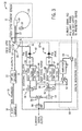
FIG. 1 is a block diagram of an embodiment of a fiber optic current sensing system, in accordance with the present embodiments; -
FIG. 2 is an embodiment of the fiber optic current sensing system ofFIG. 1 including a monitoring circuit, in accordance with the present embodiments; and -
FIG. 3 is an embodiment of the fiber optic current sensing system ofFIG. 2 including a reduction of components, in accordance with the present embodiments. -
FIG. 4 is an embodiment of the fiber optic current sensing system ofFIG. 2 including an additional monitoring circuit, in accordance with the present embodiments. -
FIG. 5 is an embodiment of the fiber optic current sensing system ofFIG. 4 including offset indication circuitry, in accordance with the present embodiments. - One or more specific embodiments of the present invention will be described below. In an effort to provide a concise description of these embodiments, all features of an actual implementation may not be described in the specification. It should be appreciated that in the development of any such actual implementation, as in any engineering or design project, numerous implementation-specific decisions must be made to achieve the developers' specific goals, such as compliance with system-related and business-related constraints, which may vary from one implementation to another. Moreover, it should be appreciated that such a development effort might be complex and time consuming, but would nevertheless be a routine undertaking of design, fabrication, and manufacture for those of ordinary skill having the benefit of this disclosure.
- When introducing elements of various embodiments of the present invention, the articles "a," "an," and "the" are intended to mean that there are one or more of the elements. The terms "comprising," "including," and "having" are intended to be inclusive and mean that there may be additional elements other than the listed elements.
- The present embodiments relate to a fiber optic current sensing device, which may include fiber optic operational health monitoring circuitry to provide diagnostic information about the operation and functionality of the fiber optic current sensing device. For example, the operational health monitoring circuitry may be included as part of the fiber optic current sensing device specifically to provide diagnostic data regarding the operation of the fiber optic current sensing device itself. Specifically, the operational health monitoring circuitry may monitor the direct current (DC) components of detected current signals for a variation in offset voltage outside of an expected and/or specified voltage range, which may be indicative of a failing operational health or condition of a light source or other components of the fiber optic current sensing device. In another embodiment, the operational health monitoring circuitry may monitor the alternating current (AC) components of detected current signals as an indication of a failing operational health of one or more high pass filters that may be included in the fiber optic operational health monitoring circuitry. In this way, the operational health monitoring circuitry may produce an external output signal (e.g., which may be output to a protection device or a utility control center) that be used to monitor the operational health and/or robustness of the light source and indicate when and/or if preventative maintenance may be required. Specifically, by providing the fiber optic operational health monitoring circuitry, a utility or other utility service provider may be provided with real-time or near time diagnostic information regarding, for example, power attenuation or gain of the light source, insertion loss and/or isolation, and so forth. This may contribute to greater reliability of the fiber optic current sensing device, and, thus allow for an increase in the accuracy of current measurements made by the fiber optic current sensing device, as well as the widespread utilization of fiber optic current sensing devices as opposed to other current sensors such as core-based current transformers (CT) and/or Rogowski coils.
- With the foregoing in mind, it may be useful to describe an embodiment of a fiber optic current sensing system, such as the fiber optic
current sensing system 10 illustrated inFIG. 1 . The fiber opticcurrent sensing system 10 may include a system for measuring a current flowing through, for example, one or more electric power conductors. As illustrated, thesystem 10 may include a fiber optic current sensor (FOCS) 12 (e.g., or other fiber optic current transducer (FOCT)), which may be coupled to alight source 16 that outputs alight 18 to anoptical splitter 20 and anoptical circulator 22 along, for example, an optical fiber. As further illustrated, the fiber opticcurrent sensor 12 may be communicatively coupled to decodingcircuitry 14. The fiber opticcurrent sensor 12 may include anoptical box 24, aflint glass fiber 26, and areflective surface 28. - In one embodiment, the
light 18 may be a non-polarized light beam having a wavelength between approximately 1310-1550 nanometers (nm). Alternatively, thelight 18 may be any form of light that may be useful in allowing the fiber opticcurrent sensor 12 and thedecoding circuitry 14 to detect electrical current. As further depicted, thelight 18 may be passed to theoptical splitter 20. In certain embodiments, theoptical splitter 20 may include 1-to-10 optical splitter useful in splitting thelight 18 amongst approximately ten channels or more. That is, the output of thelight source 16 may be split to produce aseparate light 18 for each channel. - In certain embodiments, the
optical circulator 22 may include a three-port circulator that may allow light (e.g., light 18) entering one port to exit from another port. Specifically, thelight 18 may enter theoptical circulator 22 at afirst port 30, and exit theoptical circulator 22 at asecond port 34. In certain embodiments, the light exitingsecond port 34 may be supplied to theoptical box 24 of a fiber opticcurrent sensor 12 via a multidirectional optical fiber. Thelight 18 may enter theoptical box 24, and may be transmitted through theflint glass fiber 26. Thelight 18 may then reflect off of the reflective surface 28 (e.g., a mirror), and return to theoptical box 24 via flint theglass fiber 26. - When a current flows through, for example, a power conductor (e.g., power distribution line and/or power transmission line) to which the fiber optic
current sensor 12 may be coupled, a polarization angle of the light 18 may be rotated by an amount proportional to a magnitude of the current passing through conductor (e.g., by way of the Faraday Effect). As will be further appreciated, theoptical box 24 may then output the rotated light 18 as two different polarizations, x-polarization light 35 and y-polarization light 37. The polarization of y-polarization light 37 may be offset 90° with respect tox-polarization light 35. If no current flows through, for example, the electric power conductor, a magnitude of x-polarization light 35 may be equal to a magnitude of y-polarization light 37. On the other hand, if current flows through the conductor, the magnitude of the x-polarization light 35 and the magnitude of the y-polarization light 37 may be unequal. - In certain embodiments, the x-polarization light 35 may travel along the multidirectional
optical fiber 33 and enter theoptical circulator 22 at thesecond port 34. The x-polarization light 35 may then exit theoptical circulator 22 at athird port 32, and may be supplied to one or more diodes 40 (e.g., PIN diode) of themonitoring circuit 14. Specifically, themonitoring circuit 14 may include an x-polarization light 35processing circuitry 36 and y-polarization processing circuitry 38. The y-polarization light 37 may be supplied to a similar diode 40 (e.g., PIN diode) of the y-polarization processing circuitry 38 via a similar optical fiber. The one ormore diodes 40 may respectively convert the x-polarized light 35 and y-polarizedlight 37 into the illustrated first and secondelectrical signals - In certain embodiments, the
x-polarization processing circuitry 36 may split theelectrical signal 39 and pass theelectrical signal 39 through ahigh pass filter 42 and alow pass filter 44. Thehigh pass filter 42 may isolate an alternating current (AC) component of theelectrical signal 39, and firstlow pass filter 44 to isolate a direct current (DC) component of theelectrical signal 39. As further illustrated, adivider 46 may divide the AC component of theelectrical signal 39 by DC component of theelectrical signal 39. Specifically, the output of thedivider 46 may represent the current magnitude of the conductor (e.g., power line) being monitored by the fiber opticcurrent sensor 12. - Similarly, the y-
polarization processing circuit 38 may split theelectrical signal 41 and pass theelectrical signal 41 through ahigh pass filter 48 and alow pass filter 50. Thehigh pass filter 48 may isolate the AC component of theelectrical signal 41, and thelow pass filter 50 may isolate the DC component of theelectrical signal 41. Adivider 52 may then divide the AC component of theelectrical signal 41 by the DC component of theelectrical signal 41. In some embodiments, the y-polarizedlight 37 may be approximately 180° out of phase with x-polarized light 35, and thus the y-polarization processing circuitry 38 may further include a reciprocator 54 (e.g., which may be implemented via hardware, software, or a combination thereof) that may be used to generate a reciprocal value of the output of thedivider 52. In some embodiments, the DC components of therespective signals light source 16 in units of watts (W). For example, in one embodiment, during normal operating conditions of thesystem 10, the power oflight source 16 may include a light intensity of approximately 100 microwatts (uW). However, it should be appreciated that thelight source 16 mayoutput light 18 having various values of light intensity. - As further depicted in
FIG. 1 , thedecoding circuitry 14 may also includesummer 56, which may, for example, be implemented in hardware, software, or a combination thereof, and may be used to receive and sum the respective outputs of thedivider 46 and thereciprocator 54. Anoutput divider 56 may then multiply the output ofsummer 56 by one half, for example, output multiplier and/ordivider 58. The signal output provided by theoutput divider 56 may be a voltage signal output indicative of the current flowing through, for example, one or more electric power conductors to which the fiber opticcurrent sensor 12 may be coupled. As will be further appreciated, in certain embodiments, it may be useful to monitor the operational health and condition of the fiber opticcurrent sensing system 10, and, more specifically, the operational health and condition of thelight source 16 and/or thefiber optic sensor 12 so as to allow for more accurate information related to the currents passing through the electric power conductors (e.g., electric power lines) to be assessed. - Specifically, in some embodiments, the
light source 16 may be susceptible to degradation over time, and, by extension, the output (e.g., light 18) of thelight source 16 may be susceptible to undesirable attenuation. If left unchecked or without preventive maintenance, thelight source 16, and, by extension, thefiber optic sensor 12 may become less effective in providing an accurate measure of the current flowing through, for example, an electric power conductor. However, a utility serviceman or engineer may not have any indication as to the operational health of thelight source 16 and/or thefiber optic sensor 12, and thus thelight source 16 and/or thefiber optic sensor 12 may possibly become ineffective in accurately measuring the current output (e.g., current signal output as illustrated inFIG. 1 ) while in service. For example, should the current signal output measure a value of approximately 0 Amps or other aberrantly low value, the utility and/or utility serviceman may not have any indication as to whether this is the result of a lost electric power line, or the result of one or more components of the fiber opticcurrent sensing system 10 possibly failing. Accordingly, it may be useful to provide fiber optic sensor health monitoring circuitry as part of thedecoding circuitry 14 that may be used to produce an external signal indicative of the operational health of thelight source 16 and/or thefiber optic sensor 12. - Turning now to
FIG. 2 , which illustrates an embodiment of the fiber opticcurrent sensing system 10, in which thedecoding circuitry 14 may includehealth monitoring circuitry 60. In certain embodiments, thehealth monitoring circuitry 60 may include hardware, software, or a combination of hardware and software useful in monitoring the operational health and/or the operational state of thelight source 16 and/or thefiber optic sensor 12. As illustrated inFIG. 2 , thehealth monitoring circuitry 60 may be included as part of thedecoding circuitry 14. However, in other embodiments, it should be appreciated that thehealth monitoring circuitry 60 may be provided as an external system to thedecoding circuitry 14. - In certain embodiments, the
health monitoring circuitry 60 may provide an indication of the operational health and/or the operational state of thelight source 16 and/or thefiber optic sensor 12 based on, for example, an offset of the output signal indicating the power or intensity of the light 18 of thelight source 16. Specifically, thehealth monitoring circuitry 60 may provide an indication of the operational health and/or the operational state of thelight source 16 and/or thefiber optic sensor 12 based on the DC component of therespective signals 39 and 41 (e.g., y1, y2). Thus, as illustrated, thehealth monitoring circuitry 60 may be coupled (e.g., electrically coupled) to the output (e.g., output y1) of thelow pass filter 44 and the output (e.g., output y2) of thelow pass filter 50. - In certain embodiments, by monitoring the DC components of the
signal 39 and the DC components of thesignal 41, themonitoring circuit 60 may provide an indication of the operational health and/or the operational state of thelight source 16 and/or thefiber optic sensor 12, as the respective DC components (e.g., DC offsets) of thesignals light source 16 and thefiber optic sensor 12 are functional. Thus, variation from the expected and/or specified voltage range may be indicative of failing operational health of thelight source 16 and/or thefiber optic sensor 12, or less than desirable operational health of thelight source 16 and/or thefiber optic sensor 12. - In certain embodiments, as further illustrated by
FIG. 2 , thehealth monitoring circuitry 60 may receive the respective DC components (e.g., DC offsets) of thesignals 39 and 41 (e.g., y1, y2) and sum the respective DC components via a summingdevice 61. The summingdevice 61 may, in some embodiments, include a combination of hardware and software systems useful in combining two or more signals. The summingdevice 61 may then pass the sum of the DC components of thesignals 39 and 41 (e.g., y1, y2) to anamplifier 62. Theamplifier 62 may include, for example, one or more active solid state devices (e.g., transistor, field effect transistor (FET), and so forth) or other amplifying electronic device (e.g., operational amplifier (OpAmp)) that may be used to provide a power gain (G) (e.g., an increase or decrease in power level measured as a ratio of output power to input power or in units of decibels dB) to the output signal of the summingdevice 61, and, by consequence, the input signal to theamplifier 62. Thus, theamplifier 62 may amplify the sum of the DC components of thesignals 39 and 41 (e.g., y1, y2). In one embodiment, the power gain (G) of theamplifier 62 may be a gain ratio value of approximately 0.05. However, it should be appreciated that other gain values may be used. - As further depicted, the output of the
amplifier 62 may be summed with the output of the divider 46 (e.g., output corresponding to a quotient value of the AC component and the DC component of the electrical signal 39) and the output of the reciprocator 54 (e.g., output corresponding to the reciprocal value of the quotient value of AC component and the DC component of the electrical signal 41) via a summingdevice 64. Specifically, the aforementioned signals may be summed to reduce the number of outputs to be provided to an external control system (e.g., external monitor as illustrated inFIG. 2 ). In this way, a single output may be provided as an indication of the operational health of thelight source 16, thefiber optic sensor 12, and/or certain components of thedecoding circuitry 14 as opposed to multiple outputs. However, in other embodiments, it should be appreciated that, the respective signals themselves may provide at least some indication of the operational health of thelight source 16, thefiber optic sensor 12, and/or certain components of thedecoding circuitry 14. - In certain embodiments, the summing
device 64 may be substantially similar to the summingdevice 61. Amultiplier 66 of thehealth monitoring circuitry 60 may then receive the output of the summingdevice 64, and provide an output multiplied, for example, by one-half. As illustrated, the output of themonitoring circuitry 60 may provide an indication of the operational health and/or the operational state of thelight source 16, thefiber optic sensor 12, and/or certain components of thedecoding circuitry 14. In this way, the monitoringcircuitry 60 may produce an external output signal (e.g., which may be output to a utility control center) that be used to diagnose the health and/or robustness of the light source 16 (e.g., laser) and to determine when preventative maintenance may be required. - In certain embodiments, the monitoring
circuitry 60 may also provide for one or more specific advantages such as, in embodiments, for example, when thefiber optic sensor 12 may be coupled to a series capacitor installation along a high voltage transmission line. Particularly, in such an embodiment, certain components of the fiber opticcurrent sensing system 10 may not be accessible under normal operating conditions, and can thus only be accessed during a power outage, for example. Thus by providing themonitoring circuitry 60, the utility or other utility service provider may be provided with real-time or near time diagnostic information regarding, for example, power attenuation of thelight source 16, insertion loss and/or isolation of theoptical circulator 22, health of the amplifiers in the low pass filters 42, 44, 48, and 50 of thedecoding circuitry 14, and so forth. Themonitoring circuitry 60 may also provide indication that the fibers (e.g., fibers carrying the light signals) are functional, and also that the other components of thedecoding circuitry 14 are functional. Furthermore, as previously noted, it should be appreciated that the fiber opticcurrent sensing system 10 may include multiple output channels (e.g., 9-10 output channels), and each channel may be monitored by the monitoringcircuitry 60. Thus, the monitoringcircuitry 60 may provide an indication as to the functionality of the components of each channel. - In other embodiments, the monitoring
circuitry 60 may monitor the operational health of one or more components of the fiber opticcurrent sensing system 10 intermittently based on, for example, the value of the measured current signal output of thedecoding circuitry 14. For example, should the current signal output measure a value of approximately 0 Amps or other aberrantly low and/or high value, the monitoringcircuitry 60 may generate a output to an external control system and/or other protection device (e.g., microprocessor-based protective relay) as indication of the operational health of one or more components (e.g.,light source 16, fiber opticcurrent sensor 12, and so forth) of the fiber opticcurrent sensing system 10. Specifically, in certain embodiments, the output signal of themonitoring circuitry 60 may include an indication of the operational health of thelight source 16 and the low pass filters 44 and 50, as well as the detected current signal output. In this way, because the operational health indication is included along with the current signal output, the external control system and/or external protection device may receive an indication for each channel and determine an overall power level of thelight source 16 that may be used generate certain data trends over a period of time. Furthermore, utilizing the present techniques, the utility and/or utility serviceman, for example, may have an indication as to whether an aberrantly low and/or high value of the current output signal is due to, for example, a lost electric power line, or whether one or more components of the fiber opticcurrent sensing system 10 have become inoperable. - In another embodiment, as illustrated by
FIG. 3 , the output of theamplifier 62 may not be summed with the output of the divider 46 (e.g., output corresponding to a quotient value of the AC component and the DC component of the electrical signal 39) and the output of the reciprocator 54 (e.g., output corresponding to the reciprocal value of the quotient value of AC component and the DC component of the electrical signal 41). Instead, the output of theamplifier 62 may be directly summed with the output of thedivider 46 and the current signal output as illustrated. In this way, the output of thehealth monitoring circuitry 60 may be produced while reducing hardware and/or system complexity of thehealth monitoring circuitry 60, and, by extension, thedecoding circuitry 14. - In certain embodiments, as illustrated by
FIG. 4 , in addition to, or alternatively to thehealth monitoring circuitry 60, thedecoding circuitry 14 may also include filterhealth monitoring circuitry 68. Specifically, the filterhealth monitoring circuitry 68 may receive the respective AC components of thesignals 39 and 41 (e.g., x1, x2), and provide, for example, an indication of the operational health and/or functionality of the respective high pass filters 42 and 48. As illustrated, the filterhealth monitoring circuitry 68 may also include alow pass filter 70 used to receive the AC component of thesignal 39, and alow pass filter 72 used to receive the AC component of thesignal 41. The low pass filters 70 and 72 may respectively filter out the high frequency components (e.g., AC components) of thesignals 39 and 41 (e.g., x1, x2) and produce respective DC signals. Specifically, should the high pass filters begin to fail or become partially inoperable, then DC components may begin to become apparent in thesignals 39 and 41 (e.g., x1, x2). - In certain embodiments, a summing
device 74 may then sum the respective DC signals (e.g., corresponding to the outputs of the high pass filters 42 and 48) received from the low pass filters 70 and 72. As previously noted with respect toFIG. 2 , the respective components of thesignals device 61 of the monitoring circuitry 60) may then pass the sum of the DC signals (e.g., DC components ofsignals 39 and 41 (x1, x2)) to anamplifier 76. - As noted similarly with respect to the
amplifier 62, theamplifier 76 may include, for example, one or more active solid state devices (e.g., transistor, FET, and so forth) or other amplifying electronic device (e.g., OpAmp) that may be used to provide a power gain (G) to the output signal of the summingdevice 74, and thus amplify the output signal. Theamplifier 76 may then output an external signal (e.g., which may be output to a utility control center). Specifically, certain electrical characteristics (e.g., frequency, signal distortion, signal noise, frequency jitter, signal instability, and so forth) of the output of theamplifier 76 may be analyzed to determine the operational health of the high pass filters 42 and 48. In this way, the output of thefilter monitoring circuitry 68 may provide an indication of the operational health and/or the operational state of the high pass filters 42 and 48, and, by extension, an indication of the operational health and/or the operational state of thedecoding circuitry 14. - Turning now to
FIG. 5 , in other embodiments, in addition to, or alternatively to thehealth monitoring circuitry 60 and thefilter health monitoring 68, thedecoding circuitry 14 may also include offset monitoring circuitry that may be useful for monitoring the operational status or operational health of the multipliers and/ordividers respective dividers device 78. In one embodiment, because of the phase relationship between the output signals of thedividers device 78 may be an expected value of approximately zero. Thus, a non-zero output value of the summingdevice 78 may indicate a failing operational health or other adverse operational status of the multipliers and/ordividers - For example, the summed signal may be passed to a
low pass filter 80, and then to anamplifier 82. If, for example, the filtered and amplified signal value includes a relatively large non-zero value (e.g., voltage value of approximately 10VDC or more), then the offset monitoring circuitry may provide an indication of a failing operational health of one or more electronic components (e.g., multipliers and/ordividers 46 and 52) of thedecoding circuitry 14. On the other hand, for example, if the filtered and amplified signal value includes a relatively small non-zero value (e.g., voltage value of less than approximately 9-10VDC), then the offset monitoring circuitry may provide an indication of an offset associated with the fiber opticcurrent sensor 12, and may thus provide an indication of the operational health of the fiber opticcurrent sensor 12. - Technical effects of the disclosed embodiments relate to a fiber optic current sensing device, which may include fiber optic operational health monitoring circuitry to provide diagnostic information about the operation and functionality of the fiber optic current sensing device. For example, the operational health monitoring circuitry may be included as part of the fiber optic current sensing device specifically to provide diagnostic data regarding the operation of the fiber optic current sensing device itself. Specifically, the operational health monitoring circuitry may monitor the direct current (DC) components of detected current signals for a variation in offset voltage outside of an expected and/or specified voltage range, which may be indicative of a failing operational health or condition of a light source or other components of the fiber optic current sensing device. In another embodiment, the operational health monitoring circuitry may monitor the alternating current (AC) components of detected current signals as an indication of a failing operational health of one or more high pass filters that may be included in the fiber optic operational health monitoring circuitry. In this way, the operational health monitoring circuitry may produce an external output signal (e.g., which may be output to a protection device or a utility control center) that be used to monitor the operational health and/or robustness of the light source and indicate when and/or if preventative maintenance may be required. Specifically, by providing the fiber optic operational health monitoring circuitry, a utility or other utility service provider may be provided with real-time or near time diagnostic information regarding, for example, power attenuation or gain of the light source, insertion loss and/or isolation, and so forth.
- This written description uses examples to disclose the invention, including the best mode, and also to enable any person skilled in the art to practice the invention, including making and using any devices or systems and performing any incorporated methods. The patentable scope of the invention may be defined by the claims, and may include other examples that occur to those skilled in the art. Such other examples are intended to be within the scope of the claims if they have structural elements that do not differ from the literal language of the claims, or if they include equivalent structural elements with insubstantial differences from the literal language of the claims.
- Various aspects and embodiments of the present invention are defined by the following numbered clauses:
- 1. A system, comprising:
- fiber optic detection circuitry, comprising:
- electrical current detection circuitry configured to generate a current measurement output based on a returning light intensity received via a fiber optic current sensor; and
- fiber optic health detection circuitry communicatively coupled to the electrical current detection circuitry, wherein the fiber optic health detection circuitry is configured to:
- extract a first electrical characteristic component of the current measurement output and a second electrical characteristic component of the current measurement output; and
- generate an output signal based at least in part on an adjusted summation of the first electrical characteristic component and the second electrical characteristic component, wherein the output signal comprises an indication of an operational health of a light source communicatively coupled to the fiber optic current sensor.
- fiber optic detection circuitry, comprising:
- 2. The system of
clause 1, wherein the indication comprises an indication of a power intensity of the light received via the fiber optic current sensor. - 3. The system of
clause - 4. The system of any preceding clause, wherein the fiber optic health monitoring circuitry is configured to:
- extract a third electrical characteristic component of the current measurement output and a fourth electrical characteristic component of the current measurement output; and
- generate a second output signal based at least in part on the third electrical characteristic component and the fourth electrical characteristic component, wherein the second output signal comprises a second indication of the operational health of at least one component of the fiber optic detection circuitry.
- 5. The system of clause 4, wherein the fiber optic health monitoring circuitry is configured to receive a first alternating current (AC) component as the third electrical characteristic component and a second AC component as the fourth electrical characteristic component, and wherein the second indication comprises a presence or an absence of a direct current (DC) component in the first AC component or the second AC component.
- 6. The system of any preceding clause, wherein the light source is configured to transmit a source of light to the fiber optic current sensor.
- 7. A system, comprising:
- a laser configured to generate a light beam;
- a fiber optic current transducer (FOCT) configured to detect the light beam;
- a decoding circuitry communicatively coupled to the FOCT, wherein the decoding circuitry is configured to receive the light beam as an indication of a measurement of an electrical current and to generate a first signal and a second signal based thereon;
- a first monitoring circuitry communicatively coupled to the decoding circuitry, wherein the first monitoring circuitry is configured to:
- receive a direct current (DC) component of the first signal and a DC component of the second signal; and
- generate an output signal based at least in part on a summation of the DC component of the first signal and the DC component of the second signal, wherein the output signal comprises an indication of an operational condition of the laser or the decoding circuitry; and
- a second monitoring circuitry communicatively coupled to the decoding circuitry and the first monitoring circuitry, wherein the second monitoring circuitry is configured to:
- receive an alternating current (AC) component of the first signal and an AC component of the second signal; and
- generate a second output signal based at least in part on a second summation of a first characteristic of the AC component of the first signal and a second characteristic of the AC component of the second signal, wherein the second output signal comprises a second indication of an operational condition of one or more components of the decoding circuitry.
- 8. The system of clause 7, wherein the laser is configured to transmit the light beam to an optical splitter, and wherein the optical splitter is configured to divide the light beam into a plurality of light beams.
- 9. The system of clause 8, wherein the first monitoring circuitry is configured to generate respective output signals corresponding to each of the plurality of light beams, and wherein each of the respective output signals comprises a respective indication of the operational condition of the laser.
- 20. The system of clause 7 or 8, wherein the second monitoring circuitry is configured to generate respective output signals corresponding to each of the plurality of light beams, and wherein each of the respective output signals comprises a respective indication of the operational condition of the one or more components of the decoding circuitry.
Claims (10)
- A system, comprising:a light source (16) configured to generate a source of light (18);a fiber optic current sensor (FOCS) (12) configured to detect the source of light (18);a decoding circuitry (14) communicatively coupled to the FOCS (12), wherein the decoding circuitry (14) is configured to receive the source of light (16) as an indication of a measurement of an electrical current and to generate a first signal (39) and a second signal (41) based thereon; anda health monitoring circuitry (60) communicatively coupled to the decoding circuitry (14), wherein the health monitoring circuitry (60) is configured to:receive a first electrical characteristic component (y1) of the first signal (39) and a corresponding second electrical characteristic component (y2) of the second signal (41);generate a summation (61) of the first electrical characteristic component (y1) of the first signal (39) and the second electrical characteristic component (y2) of the second signal (41); andgenerate an output signal based at least in part on the summation (61) of the first electrical characteristic component (y1) and the second electrical characteristic component (y2), wherein the output signal comprises an indication of an operational condition of the light source. (16)
- The system of claim 1, wherein the source of light (18) comprises light of a first polarization (35), and wherein first polarization (35) comprises the indication of the measurement of the electrical current.
- The system of claim 1 or 2, wherein the source of light (18) comprises light of a second polarization (37), and wherein second polarization (37) comprises the indication of the measurement of the electrical current.
- The system of any of claims 1 to 3, wherein the light source (16) comprises a laser configured to transmit the source of light to an optical splitter (20), and wherein the optical splitter (20) is configured to divide the source of light (18) into a plurality of sources of light.
- The system of any preceding claim, wherein the health monitoring circuitry (60) is configured to receive a first direct current (DC) component (y1) as the first electrical characteristic component and a second DC component (y2) as the second electrical characteristic component.
- The system of any preceding claim, wherein the health monitoring circuitry (60) is configured to adjust a gain (G) of the summation of the first electrical characteristic component (y1) and the second electrical characteristic component (y2) before generating the output signal.
- The system of any preceding claim, wherein the health monitoring circuitry (60) is configured to:receive a third electrical characteristic component (x1) of the first signal (39) and a corresponding fourth electrical characteristic component (x2) of the second signal (41);generate a summation of the third electrical characteristic component (x1) of first signal (39) and the fourth electrical characteristic component (x2) of the second signal (41); andgenerate a second output signal based at least in part on the summation of the third electrical characteristic component (x1) and the fourth electrical characteristic component (x2), wherein the second output signal comprises a second indication of the operational condition of the light source (16).
- The system of claim 7, wherein the health monitoring circuitry (60) is configured to receive a first alternating current (AC) component (x1) as the third electrical characteristic component and a second AC component (x2) as the fourth electrical characteristic component.
- The system of claim 7 or 8, wherein the health monitoring circuitry (60) is configured to adjust a gain of the summation of the third electrical characteristic component (x1) and the fourth electrical characteristic component (x2) before generating the second output signal.
- The system of any preceding claim, wherein the health monitoring circuitry (60) is configured to generate a plurality of output signals, and wherein each output signal of the plurality of output signals corresponds to a respective one of a plurality of sources of light received by the decoding circuitry (14).
Applications Claiming Priority (1)
| Application Number | Priority Date | Filing Date | Title |
|---|---|---|---|
| US14/253,300 US9377489B2 (en) | 2014-04-15 | 2014-04-15 | Systems and methods for monitoring fiber optic current sensing systems |
Publications (2)
| Publication Number | Publication Date |
|---|---|
| EP2933644A1 true EP2933644A1 (en) | 2015-10-21 |
| EP2933644B1 EP2933644B1 (en) | 2019-10-09 |
Family
ID=52784960
Family Applications (1)
| Application Number | Title | Priority Date | Filing Date |
|---|---|---|---|
| EP15161283.5A Active EP2933644B1 (en) | 2014-04-15 | 2015-03-27 | Systems and methods for monitoring fiber optic current sensing systems |
Country Status (6)
| Country | Link |
|---|---|
| US (1) | US9377489B2 (en) |
| EP (1) | EP2933644B1 (en) |
| CN (1) | CN105021863B (en) |
| BR (1) | BR102015007109B1 (en) |
| CA (1) | CA2887002C (en) |
| ZA (1) | ZA201502182B (en) |
Families Citing this family (4)
| Publication number | Priority date | Publication date | Assignee | Title |
|---|---|---|---|---|
| JP6726033B2 (en) * | 2016-06-01 | 2020-07-22 | 九電テクノシステムズ株式会社 | Current detector |
| US10608440B2 (en) * | 2016-08-31 | 2020-03-31 | Te Connectivity Corporation | Control circuit configured to determine when a direct current component in an alternating current power line passes a designated threshold |
| EP3776032A1 (en) * | 2018-04-12 | 2021-02-17 | ABB Power Grids Switzerland AG | A spliced optical fiber with splice protection, current sensor with such spliced optical fiber and method for protecting a spliced optical fiber |
| CN116718972B (en) * | 2023-05-08 | 2025-11-14 | 中国电力科学研究院有限公司 | Simulation Model and Simulation Test Method of All-Fiber Optic Current Transformer |
Citations (4)
| Publication number | Priority date | Publication date | Assignee | Title |
|---|---|---|---|---|
| EP0458429A2 (en) * | 1990-04-25 | 1991-11-27 | Mitsubishi Denki Kabushiki Kaisha | Optical measurement device |
| US5149962A (en) * | 1991-06-03 | 1992-09-22 | Simmonds Precision Products, Inc. | Proximity detector using faraday effect and bidirectional transmission |
| US5847560A (en) * | 1994-09-09 | 1998-12-08 | Siemens Aktiengsellschaft | Process and device for measuring an alternating electric current with temperature compensation |
| US20100253320A1 (en) * | 2007-10-23 | 2010-10-07 | Tokyo Electric Power Company, Incorporated | Optical fiber electric current sensor and electric current measurement method |
Family Cites Families (24)
| Publication number | Priority date | Publication date | Assignee | Title |
|---|---|---|---|---|
| US4612500A (en) * | 1984-09-04 | 1986-09-16 | Westinghouse Electric Corp. | Temperature stabilized Faraday rotator current sensor by thermal mechanical means |
| CN2060892U (en) * | 1988-12-22 | 1990-08-22 | 清华大学 | Modulated light source closed-loop detection fiber optic current sensor |
| US6434285B1 (en) * | 1998-12-31 | 2002-08-13 | Nxtphase Technologies Srl | Fiber optic difference current sensor |
| US6670799B1 (en) | 2000-05-03 | 2003-12-30 | Nxt Phase Corporation | Optical current measuring for high voltage systems |
| DE10021669A1 (en) | 2000-05-05 | 2001-11-08 | Abb Research Ltd | Fiber optic current sensor |
| FR2811085B1 (en) | 2000-06-30 | 2002-08-23 | Schneider Electric Ind Sa | DEVICE FOR MEASURING AN ELECTRIC CURRENT BY FARADAY EFFECT |
| US7233746B2 (en) | 2002-01-30 | 2007-06-19 | Blake James N | Wide dynamic range sensor signal processing method & circuitry for analog and digital information signals |
| US20040021100A1 (en) * | 2002-04-12 | 2004-02-05 | Mikhail Gouzman | Fiber-optic sensor for measuring level of fluid |
| ATE443873T1 (en) * | 2004-11-18 | 2009-10-15 | Powersense As | COMPENSATION OF SIMPLE FIBER OPTICAL FARADAY EFFECT SENSORS |
| US7786719B2 (en) | 2005-03-08 | 2010-08-31 | The Tokyo Electric Power Company, Incorporated | Optical sensor, optical current sensor and optical voltage sensor |
| WO2006095619A1 (en) | 2005-03-08 | 2006-09-14 | The Tokyo Electric Power Company, Incorporated | Intensity modulation type photo-sensor and photo-current/voltage sensor |
| CN101600968B (en) | 2006-12-22 | 2013-01-02 | Abb研究有限公司 | Optical voltage sensor |
| US20100194379A1 (en) | 2007-09-10 | 2010-08-05 | Kiyoshi Kurosawa | Optical fiber electric current measurement apparatus and electric current measurement method |
| US20100309473A1 (en) * | 2007-12-21 | 2010-12-09 | Honeywell International Inc. | Fiber optic current sensor and method for sensing current using the same |
| EP2223129A1 (en) | 2007-12-21 | 2010-09-01 | ABB Research Ltd. | Gas-insulated switchgear device with optical current sensor |
| DE112010003627T5 (en) * | 2009-09-11 | 2012-11-22 | Alstom Grid Inc. | Fiber optic master-slave current sensors for differential protection schemes |
| US8395372B2 (en) | 2009-10-28 | 2013-03-12 | Optisense Network, Llc | Method for measuring current in an electric power distribution system |
| JP5904694B2 (en) * | 2009-12-10 | 2016-04-20 | 株式会社東芝 | Sagnac interferometric photocurrent sensor |
| US9222830B2 (en) * | 2010-06-17 | 2015-12-29 | Research Foundation Of The State University Of New York | Optical control sensor system with driver that switches frequencies of a set of different orthogonal signals and modulates the intensity of light |
| CN102243258B (en) * | 2011-04-13 | 2014-01-29 | 华北电力大学 | Modulation type optical current transducer and method thereof for measuring alternating current and direct current |
| US8781266B2 (en) | 2011-12-23 | 2014-07-15 | General Electric Company | Distributed, multiplexed fiber optic current transducer using optical power division |
| CN102830258B (en) * | 2012-08-24 | 2016-01-13 | 易能(中国)电力科技有限公司 | Optical current sensor-based system and current measuring method |
| US9465052B2 (en) * | 2013-06-10 | 2016-10-11 | General Electric Company | Systems and methods for monitoring fiber optic current sensing systems |
| CN103698571B (en) * | 2014-01-03 | 2016-06-29 | 东南大学 | There is current transformer arrangement and the bus current detection method of self energizing low-power consumption |
-
2014
- 2014-04-15 US US14/253,300 patent/US9377489B2/en active Active
-
2015
- 2015-03-27 EP EP15161283.5A patent/EP2933644B1/en active Active
- 2015-03-30 ZA ZA2015/02182A patent/ZA201502182B/en unknown
- 2015-03-30 BR BR102015007109-4A patent/BR102015007109B1/en active IP Right Grant
- 2015-04-02 CA CA2887002A patent/CA2887002C/en active Active
- 2015-04-15 CN CN201510177076.6A patent/CN105021863B/en active Active
Patent Citations (4)
| Publication number | Priority date | Publication date | Assignee | Title |
|---|---|---|---|---|
| EP0458429A2 (en) * | 1990-04-25 | 1991-11-27 | Mitsubishi Denki Kabushiki Kaisha | Optical measurement device |
| US5149962A (en) * | 1991-06-03 | 1992-09-22 | Simmonds Precision Products, Inc. | Proximity detector using faraday effect and bidirectional transmission |
| US5847560A (en) * | 1994-09-09 | 1998-12-08 | Siemens Aktiengsellschaft | Process and device for measuring an alternating electric current with temperature compensation |
| US20100253320A1 (en) * | 2007-10-23 | 2010-10-07 | Tokyo Electric Power Company, Incorporated | Optical fiber electric current sensor and electric current measurement method |
Also Published As
| Publication number | Publication date |
|---|---|
| BR102015007109A2 (en) | 2017-11-28 |
| CA2887002A1 (en) | 2015-10-15 |
| US9377489B2 (en) | 2016-06-28 |
| US20150293154A1 (en) | 2015-10-15 |
| CN105021863B (en) | 2020-08-21 |
| EP2933644B1 (en) | 2019-10-09 |
| BR102015007109B1 (en) | 2021-12-14 |
| CA2887002C (en) | 2022-12-06 |
| ZA201502182B (en) | 2016-01-27 |
| CN105021863A (en) | 2015-11-04 |
Similar Documents
| Publication | Publication Date | Title |
|---|---|---|
| US12111338B2 (en) | Reflective current and magnetic sensors based on optical sensing with integrated temperature sensing | |
| JP5083321B2 (en) | Optical fiber current measuring device and current measuring method | |
| EP2933644B1 (en) | Systems and methods for monitoring fiber optic current sensing systems | |
| US10191090B2 (en) | Power transformers using optical current sensors | |
| JP2010025766A (en) | Fiber-optic current sensor, current measurement method and accident area detection device | |
| JP6726033B2 (en) | Current detector | |
| CA2925248C (en) | Optical current transducer with offset cancellation and current linearization | |
| CN105445519B (en) | A kind of optical fiber current mutual inductor that dual wavelength works and the method for measuring electric current | |
| JP6027927B2 (en) | Fiber optic current sensor | |
| CA2923916C (en) | Current transducer with offset cancellation | |
| CN212752265U (en) | A System Using EDFA Amplifier to Detect Rayleigh Scattering Signal Intensity | |
| CA2783295C (en) | Magneto optical current transducer with improved outage performance | |
| KR100307639B1 (en) | Current / temperature measurement optical sensor using multi-wavelength light source and its method | |
| KR100288157B1 (en) | Optoelectronic Overcurrent Protection Relay System | |
| JP4065243B2 (en) | Optical CT with failure judgment function | |
| Kim et al. | Application of an Optical Current Transformer For Measuring High Current | |
| JP2001356137A (en) | Optical application measuring device and protection control device using this device | |
| JP2009128208A (en) | Optical CT application equipment | |
| JPS601582A (en) | Measuring apparatus for both ac and dc magnetic fields |
Legal Events
| Date | Code | Title | Description |
|---|---|---|---|
| PUAI | Public reference made under article 153(3) epc to a published international application that has entered the european phase |
Free format text: ORIGINAL CODE: 0009012 |
|
| AK | Designated contracting states |
Kind code of ref document: A1 Designated state(s): AL AT BE BG CH CY CZ DE DK EE ES FI FR GB GR HR HU IE IS IT LI LT LU LV MC MK MT NL NO PL PT RO RS SE SI SK SM TR |
|
| AX | Request for extension of the european patent |
Extension state: BA ME |
|
| 17P | Request for examination filed |
Effective date: 20160421 |
|
| RBV | Designated contracting states (corrected) |
Designated state(s): AL AT BE BG CH CY CZ DE DK EE ES FI FR GB GR HR HU IE IS IT LI LT LU LV MC MK MT NL NO PL PT RO RS SE SI SK SM TR |
|
| RIN1 | Information on inventor provided before grant (corrected) |
Inventor name: WALLACE, DANIEL ROBERT Inventor name: MARKEN, PAUL EDWARD |
|
| REG | Reference to a national code |
Ref country code: DE Ref legal event code: R079 Ref document number: 602015039345 Country of ref document: DE Free format text: PREVIOUS MAIN CLASS: G01R0015240000 Ipc: G01R0035000000 |
|
| GRAP | Despatch of communication of intention to grant a patent |
Free format text: ORIGINAL CODE: EPIDOSNIGR1 |
|
| STAA | Information on the status of an ep patent application or granted ep patent |
Free format text: STATUS: GRANT OF PATENT IS INTENDED |
|
| RIC1 | Information provided on ipc code assigned before grant |
Ipc: G01R 31/28 20060101ALI20190411BHEP Ipc: G01R 15/24 20060101ALI20190411BHEP Ipc: G01R 15/22 20060101ALI20190411BHEP Ipc: G01R 35/00 20060101AFI20190411BHEP |
|
| INTG | Intention to grant announced |
Effective date: 20190506 |
|
| GRAS | Grant fee paid |
Free format text: ORIGINAL CODE: EPIDOSNIGR3 |
|
| GRAA | (expected) grant |
Free format text: ORIGINAL CODE: 0009210 |
|
| STAA | Information on the status of an ep patent application or granted ep patent |
Free format text: STATUS: THE PATENT HAS BEEN GRANTED |
|
| AK | Designated contracting states |
Kind code of ref document: B1 Designated state(s): AL AT BE BG CH CY CZ DE DK EE ES FI FR GB GR HR HU IE IS IT LI LT LU LV MC MK MT NL NO PL PT RO RS SE SI SK SM TR |
|
| REG | Reference to a national code |
Ref country code: GB Ref legal event code: FG4D |
|
| REG | Reference to a national code |
Ref country code: CH Ref legal event code: EP |
|
| REG | Reference to a national code |
Ref country code: IE Ref legal event code: FG4D |
|
| REG | Reference to a national code |
Ref country code: DE Ref legal event code: R096 Ref document number: 602015039345 Country of ref document: DE |
|
| REG | Reference to a national code |
Ref country code: AT Ref legal event code: REF Ref document number: 1189460 Country of ref document: AT Kind code of ref document: T Effective date: 20191115 |
|
| REG | Reference to a national code |
Ref country code: FI Ref legal event code: FGE |
|
| REG | Reference to a national code |
Ref country code: SE Ref legal event code: TRGR |
|
| REG | Reference to a national code |
Ref country code: NL Ref legal event code: MP Effective date: 20191009 |
|
| REG | Reference to a national code |
Ref country code: LT Ref legal event code: MG4D |
|
| REG | Reference to a national code |
Ref country code: AT Ref legal event code: MK05 Ref document number: 1189460 Country of ref document: AT Kind code of ref document: T Effective date: 20191009 |
|
| PG25 | Lapsed in a contracting state [announced via postgrant information from national office to epo] |
Ref country code: BG Free format text: LAPSE BECAUSE OF FAILURE TO SUBMIT A TRANSLATION OF THE DESCRIPTION OR TO PAY THE FEE WITHIN THE PRESCRIBED TIME-LIMIT Effective date: 20200109 Ref country code: NO Free format text: LAPSE BECAUSE OF FAILURE TO SUBMIT A TRANSLATION OF THE DESCRIPTION OR TO PAY THE FEE WITHIN THE PRESCRIBED TIME-LIMIT Effective date: 20200109 Ref country code: LT Free format text: LAPSE BECAUSE OF FAILURE TO SUBMIT A TRANSLATION OF THE DESCRIPTION OR TO PAY THE FEE WITHIN THE PRESCRIBED TIME-LIMIT Effective date: 20191009 Ref country code: PL Free format text: LAPSE BECAUSE OF FAILURE TO SUBMIT A TRANSLATION OF THE DESCRIPTION OR TO PAY THE FEE WITHIN THE PRESCRIBED TIME-LIMIT Effective date: 20191009 Ref country code: NL Free format text: LAPSE BECAUSE OF FAILURE TO SUBMIT A TRANSLATION OF THE DESCRIPTION OR TO PAY THE FEE WITHIN THE PRESCRIBED TIME-LIMIT Effective date: 20191009 Ref country code: AT Free format text: LAPSE BECAUSE OF FAILURE TO SUBMIT A TRANSLATION OF THE DESCRIPTION OR TO PAY THE FEE WITHIN THE PRESCRIBED TIME-LIMIT Effective date: 20191009 Ref country code: ES Free format text: LAPSE BECAUSE OF FAILURE TO SUBMIT A TRANSLATION OF THE DESCRIPTION OR TO PAY THE FEE WITHIN THE PRESCRIBED TIME-LIMIT Effective date: 20191009 Ref country code: PT Free format text: LAPSE BECAUSE OF FAILURE TO SUBMIT A TRANSLATION OF THE DESCRIPTION OR TO PAY THE FEE WITHIN THE PRESCRIBED TIME-LIMIT Effective date: 20200210 Ref country code: GR Free format text: LAPSE BECAUSE OF FAILURE TO SUBMIT A TRANSLATION OF THE DESCRIPTION OR TO PAY THE FEE WITHIN THE PRESCRIBED TIME-LIMIT Effective date: 20200110 Ref country code: LV Free format text: LAPSE BECAUSE OF FAILURE TO SUBMIT A TRANSLATION OF THE DESCRIPTION OR TO PAY THE FEE WITHIN THE PRESCRIBED TIME-LIMIT Effective date: 20191009 |
|
| PG25 | Lapsed in a contracting state [announced via postgrant information from national office to epo] |
Ref country code: RS Free format text: LAPSE BECAUSE OF FAILURE TO SUBMIT A TRANSLATION OF THE DESCRIPTION OR TO PAY THE FEE WITHIN THE PRESCRIBED TIME-LIMIT Effective date: 20191009 Ref country code: HR Free format text: LAPSE BECAUSE OF FAILURE TO SUBMIT A TRANSLATION OF THE DESCRIPTION OR TO PAY THE FEE WITHIN THE PRESCRIBED TIME-LIMIT Effective date: 20191009 Ref country code: IS Free format text: LAPSE BECAUSE OF FAILURE TO SUBMIT A TRANSLATION OF THE DESCRIPTION OR TO PAY THE FEE WITHIN THE PRESCRIBED TIME-LIMIT Effective date: 20200224 |
|
| PG25 | Lapsed in a contracting state [announced via postgrant information from national office to epo] |
Ref country code: AL Free format text: LAPSE BECAUSE OF FAILURE TO SUBMIT A TRANSLATION OF THE DESCRIPTION OR TO PAY THE FEE WITHIN THE PRESCRIBED TIME-LIMIT Effective date: 20191009 |
|
| REG | Reference to a national code |
Ref country code: DE Ref legal event code: R097 Ref document number: 602015039345 Country of ref document: DE |
|
| PG2D | Information on lapse in contracting state deleted |
Ref country code: IS |
|
| PG25 | Lapsed in a contracting state [announced via postgrant information from national office to epo] |
Ref country code: RO Free format text: LAPSE BECAUSE OF FAILURE TO SUBMIT A TRANSLATION OF THE DESCRIPTION OR TO PAY THE FEE WITHIN THE PRESCRIBED TIME-LIMIT Effective date: 20191009 Ref country code: CZ Free format text: LAPSE BECAUSE OF FAILURE TO SUBMIT A TRANSLATION OF THE DESCRIPTION OR TO PAY THE FEE WITHIN THE PRESCRIBED TIME-LIMIT Effective date: 20191009 Ref country code: DK Free format text: LAPSE BECAUSE OF FAILURE TO SUBMIT A TRANSLATION OF THE DESCRIPTION OR TO PAY THE FEE WITHIN THE PRESCRIBED TIME-LIMIT Effective date: 20191009 Ref country code: EE Free format text: LAPSE BECAUSE OF FAILURE TO SUBMIT A TRANSLATION OF THE DESCRIPTION OR TO PAY THE FEE WITHIN THE PRESCRIBED TIME-LIMIT Effective date: 20191009 Ref country code: IS Free format text: LAPSE BECAUSE OF FAILURE TO SUBMIT A TRANSLATION OF THE DESCRIPTION OR TO PAY THE FEE WITHIN THE PRESCRIBED TIME-LIMIT Effective date: 20200209 |
|
| PLBE | No opposition filed within time limit |
Free format text: ORIGINAL CODE: 0009261 |
|
| STAA | Information on the status of an ep patent application or granted ep patent |
Free format text: STATUS: NO OPPOSITION FILED WITHIN TIME LIMIT |
|
| PG25 | Lapsed in a contracting state [announced via postgrant information from national office to epo] |
Ref country code: SK Free format text: LAPSE BECAUSE OF FAILURE TO SUBMIT A TRANSLATION OF THE DESCRIPTION OR TO PAY THE FEE WITHIN THE PRESCRIBED TIME-LIMIT Effective date: 20191009 Ref country code: SM Free format text: LAPSE BECAUSE OF FAILURE TO SUBMIT A TRANSLATION OF THE DESCRIPTION OR TO PAY THE FEE WITHIN THE PRESCRIBED TIME-LIMIT Effective date: 20191009 Ref country code: IT Free format text: LAPSE BECAUSE OF FAILURE TO SUBMIT A TRANSLATION OF THE DESCRIPTION OR TO PAY THE FEE WITHIN THE PRESCRIBED TIME-LIMIT Effective date: 20191009 |
|
| 26N | No opposition filed |
Effective date: 20200710 |
|
| PG25 | Lapsed in a contracting state [announced via postgrant information from national office to epo] |
Ref country code: MC Free format text: LAPSE BECAUSE OF FAILURE TO SUBMIT A TRANSLATION OF THE DESCRIPTION OR TO PAY THE FEE WITHIN THE PRESCRIBED TIME-LIMIT Effective date: 20191009 |
|
| REG | Reference to a national code |
Ref country code: CH Ref legal event code: PL |
|
| PG25 | Lapsed in a contracting state [announced via postgrant information from national office to epo] |
Ref country code: SI Free format text: LAPSE BECAUSE OF FAILURE TO SUBMIT A TRANSLATION OF THE DESCRIPTION OR TO PAY THE FEE WITHIN THE PRESCRIBED TIME-LIMIT Effective date: 20191009 |
|
| REG | Reference to a national code |
Ref country code: BE Ref legal event code: MM Effective date: 20200331 |
|
| PG25 | Lapsed in a contracting state [announced via postgrant information from national office to epo] |
Ref country code: LU Free format text: LAPSE BECAUSE OF NON-PAYMENT OF DUE FEES Effective date: 20200327 |
|
| PG25 | Lapsed in a contracting state [announced via postgrant information from national office to epo] |
Ref country code: IE Free format text: LAPSE BECAUSE OF NON-PAYMENT OF DUE FEES Effective date: 20200327 Ref country code: LI Free format text: LAPSE BECAUSE OF NON-PAYMENT OF DUE FEES Effective date: 20200331 Ref country code: FR Free format text: LAPSE BECAUSE OF NON-PAYMENT OF DUE FEES Effective date: 20200331 Ref country code: CH Free format text: LAPSE BECAUSE OF NON-PAYMENT OF DUE FEES Effective date: 20200331 |
|
| PG25 | Lapsed in a contracting state [announced via postgrant information from national office to epo] |
Ref country code: BE Free format text: LAPSE BECAUSE OF NON-PAYMENT OF DUE FEES Effective date: 20200331 |
|
| PG25 | Lapsed in a contracting state [announced via postgrant information from national office to epo] |
Ref country code: TR Free format text: LAPSE BECAUSE OF FAILURE TO SUBMIT A TRANSLATION OF THE DESCRIPTION OR TO PAY THE FEE WITHIN THE PRESCRIBED TIME-LIMIT Effective date: 20191009 Ref country code: MT Free format text: LAPSE BECAUSE OF FAILURE TO SUBMIT A TRANSLATION OF THE DESCRIPTION OR TO PAY THE FEE WITHIN THE PRESCRIBED TIME-LIMIT Effective date: 20191009 Ref country code: CY Free format text: LAPSE BECAUSE OF FAILURE TO SUBMIT A TRANSLATION OF THE DESCRIPTION OR TO PAY THE FEE WITHIN THE PRESCRIBED TIME-LIMIT Effective date: 20191009 |
|
| PG25 | Lapsed in a contracting state [announced via postgrant information from national office to epo] |
Ref country code: MK Free format text: LAPSE BECAUSE OF FAILURE TO SUBMIT A TRANSLATION OF THE DESCRIPTION OR TO PAY THE FEE WITHIN THE PRESCRIBED TIME-LIMIT Effective date: 20191009 |
|
| P01 | Opt-out of the competence of the unified patent court (upc) registered |
Effective date: 20230522 |
|
| REG | Reference to a national code |
Ref country code: FI Ref legal event code: PCE Owner name: GENERAL ELECTRIC TECHNOLOGY GMBH |
|
| REG | Reference to a national code |
Ref country code: DE Ref legal event code: R081 Ref document number: 602015039345 Country of ref document: DE Owner name: GENERAL ELECTRIC TECHNOLOGY GMBH, CH Free format text: FORMER OWNER: GENERAL ELECTRIC CO., SCHENECTADY, N.Y., US |
|
| REG | Reference to a national code |
Ref country code: GB Ref legal event code: 732E Free format text: REGISTERED BETWEEN 20240222 AND 20240228 |
|
| PGFP | Annual fee paid to national office [announced via postgrant information from national office to epo] |
Ref country code: SE Payment date: 20260219 Year of fee payment: 12 |
|
| PGFP | Annual fee paid to national office [announced via postgrant information from national office to epo] |
Ref country code: GB Payment date: 20260220 Year of fee payment: 12 |
|
| PGFP | Annual fee paid to national office [announced via postgrant information from national office to epo] |
Ref country code: DE Payment date: 20260219 Year of fee payment: 12 |
|
| PGFP | Annual fee paid to national office [announced via postgrant information from national office to epo] |
Ref country code: FI Payment date: 20260219 Year of fee payment: 12 |