EP2933477B1 - SYSTEM UND VERFAHREN ZUR Steuerung DER SCHUBKRAFT und der GESCHWINDIGKEIT EINER WINDTURBINE - Google Patents
SYSTEM UND VERFAHREN ZUR Steuerung DER SCHUBKRAFT und der GESCHWINDIGKEIT EINER WINDTURBINE Download PDFInfo
- Publication number
- EP2933477B1 EP2933477B1 EP15160454.3A EP15160454A EP2933477B1 EP 2933477 B1 EP2933477 B1 EP 2933477B1 EP 15160454 A EP15160454 A EP 15160454A EP 2933477 B1 EP2933477 B1 EP 2933477B1
- Authority
- EP
- European Patent Office
- Prior art keywords
- speed
- thrust
- set point
- wind turbine
- actual
- Prior art date
- Legal status (The legal status is an assumption and is not a legal conclusion. Google has not performed a legal analysis and makes no representation as to the accuracy of the status listed.)
- Active
Links
- 238000000034 method Methods 0.000 title claims description 28
- 230000004044 response Effects 0.000 claims description 38
- 230000008859 change Effects 0.000 claims description 31
- 238000005452 bending Methods 0.000 claims description 24
- 230000035945 sensitivity Effects 0.000 claims description 18
- 230000001276 controlling effect Effects 0.000 claims description 8
- 230000001105 regulatory effect Effects 0.000 claims description 8
- 238000013461 design Methods 0.000 claims description 5
- 238000012546 transfer Methods 0.000 claims description 2
- 239000013598 vector Substances 0.000 description 10
- 230000006870 function Effects 0.000 description 8
- 238000010586 diagram Methods 0.000 description 6
- 230000000694 effects Effects 0.000 description 6
- 230000008901 benefit Effects 0.000 description 5
- 238000004891 communication Methods 0.000 description 5
- 238000005259 measurement Methods 0.000 description 5
- 230000007246 mechanism Effects 0.000 description 5
- 230000009467 reduction Effects 0.000 description 5
- 238000013459 approach Methods 0.000 description 4
- 238000005516 engineering process Methods 0.000 description 4
- 230000009471 action Effects 0.000 description 3
- 238000004364 calculation method Methods 0.000 description 3
- 238000004519 manufacturing process Methods 0.000 description 3
- 230000001133 acceleration Effects 0.000 description 2
- 238000005094 computer simulation Methods 0.000 description 2
- 238000004146 energy storage Methods 0.000 description 2
- 238000001914 filtration Methods 0.000 description 2
- 230000033001 locomotion Effects 0.000 description 2
- 230000007774 longterm Effects 0.000 description 2
- 239000000463 material Substances 0.000 description 2
- 238000012986 modification Methods 0.000 description 2
- 230000004048 modification Effects 0.000 description 2
- 238000012544 monitoring process Methods 0.000 description 2
- 238000012545 processing Methods 0.000 description 2
- 238000007493 shaping process Methods 0.000 description 2
- 230000001052 transient effect Effects 0.000 description 2
- 238000012935 Averaging Methods 0.000 description 1
- 208000019300 CLIPPERS Diseases 0.000 description 1
- 230000009286 beneficial effect Effects 0.000 description 1
- 238000004422 calculation algorithm Methods 0.000 description 1
- 208000021930 chronic lymphocytic inflammation with pontine perivascular enhancement responsive to steroids Diseases 0.000 description 1
- 238000011217 control strategy Methods 0.000 description 1
- 238000007796 conventional method Methods 0.000 description 1
- 238000012937 correction Methods 0.000 description 1
- 230000008878 coupling Effects 0.000 description 1
- 238000010168 coupling process Methods 0.000 description 1
- 238000005859 coupling reaction Methods 0.000 description 1
- 230000003247 decreasing effect Effects 0.000 description 1
- 238000001514 detection method Methods 0.000 description 1
- 238000011161 development Methods 0.000 description 1
- 230000018109 developmental process Effects 0.000 description 1
- 230000008713 feedback mechanism Effects 0.000 description 1
- 239000000835 fiber Substances 0.000 description 1
- 230000006872 improvement Effects 0.000 description 1
- 230000003287 optical effect Effects 0.000 description 1
- 238000005457 optimization Methods 0.000 description 1
- 238000012913 prioritisation Methods 0.000 description 1
- 238000000926 separation method Methods 0.000 description 1
- 230000000007 visual effect Effects 0.000 description 1
- 238000012800 visualization Methods 0.000 description 1
Images


Classifications
-
- F—MECHANICAL ENGINEERING; LIGHTING; HEATING; WEAPONS; BLASTING
- F03—MACHINES OR ENGINES FOR LIQUIDS; WIND, SPRING, OR WEIGHT MOTORS; PRODUCING MECHANICAL POWER OR A REACTIVE PROPULSIVE THRUST, NOT OTHERWISE PROVIDED FOR
- F03D—WIND MOTORS
- F03D7/00—Controlling wind motors
- F03D7/02—Controlling wind motors the wind motors having rotation axis substantially parallel to the air flow entering the rotor
- F03D7/0276—Controlling wind motors the wind motors having rotation axis substantially parallel to the air flow entering the rotor controlling rotor speed, e.g. variable speed
-
- F—MECHANICAL ENGINEERING; LIGHTING; HEATING; WEAPONS; BLASTING
- F03—MACHINES OR ENGINES FOR LIQUIDS; WIND, SPRING, OR WEIGHT MOTORS; PRODUCING MECHANICAL POWER OR A REACTIVE PROPULSIVE THRUST, NOT OTHERWISE PROVIDED FOR
- F03D—WIND MOTORS
- F03D7/00—Controlling wind motors
- F03D7/02—Controlling wind motors the wind motors having rotation axis substantially parallel to the air flow entering the rotor
- F03D7/022—Adjusting aerodynamic properties of the blades
- F03D7/0224—Adjusting blade pitch
-
- F—MECHANICAL ENGINEERING; LIGHTING; HEATING; WEAPONS; BLASTING
- F03—MACHINES OR ENGINES FOR LIQUIDS; WIND, SPRING, OR WEIGHT MOTORS; PRODUCING MECHANICAL POWER OR A REACTIVE PROPULSIVE THRUST, NOT OTHERWISE PROVIDED FOR
- F03D—WIND MOTORS
- F03D7/00—Controlling wind motors
- F03D7/02—Controlling wind motors the wind motors having rotation axis substantially parallel to the air flow entering the rotor
- F03D7/028—Controlling wind motors the wind motors having rotation axis substantially parallel to the air flow entering the rotor controlling wind motor output power
-
- F—MECHANICAL ENGINEERING; LIGHTING; HEATING; WEAPONS; BLASTING
- F03—MACHINES OR ENGINES FOR LIQUIDS; WIND, SPRING, OR WEIGHT MOTORS; PRODUCING MECHANICAL POWER OR A REACTIVE PROPULSIVE THRUST, NOT OTHERWISE PROVIDED FOR
- F03D—WIND MOTORS
- F03D7/00—Controlling wind motors
- F03D7/02—Controlling wind motors the wind motors having rotation axis substantially parallel to the air flow entering the rotor
- F03D7/04—Automatic control; Regulation
- F03D7/042—Automatic control; Regulation by means of an electrical or electronic controller
- F03D7/043—Automatic control; Regulation by means of an electrical or electronic controller characterised by the type of control logic
- F03D7/045—Automatic control; Regulation by means of an electrical or electronic controller characterised by the type of control logic with model-based controls
-
- F—MECHANICAL ENGINEERING; LIGHTING; HEATING; WEAPONS; BLASTING
- F03—MACHINES OR ENGINES FOR LIQUIDS; WIND, SPRING, OR WEIGHT MOTORS; PRODUCING MECHANICAL POWER OR A REACTIVE PROPULSIVE THRUST, NOT OTHERWISE PROVIDED FOR
- F03D—WIND MOTORS
- F03D9/00—Adaptations of wind motors for special use; Combinations of wind motors with apparatus driven thereby; Wind motors specially adapted for installation in particular locations
- F03D9/20—Wind motors characterised by the driven apparatus
- F03D9/25—Wind motors characterised by the driven apparatus the apparatus being an electrical generator
-
- F—MECHANICAL ENGINEERING; LIGHTING; HEATING; WEAPONS; BLASTING
- F03—MACHINES OR ENGINES FOR LIQUIDS; WIND, SPRING, OR WEIGHT MOTORS; PRODUCING MECHANICAL POWER OR A REACTIVE PROPULSIVE THRUST, NOT OTHERWISE PROVIDED FOR
- F03D—WIND MOTORS
- F03D80/00—Details, components or accessories not provided for in groups F03D1/00 - F03D17/00
- F03D80/70—Bearing or lubricating arrangements
-
- F—MECHANICAL ENGINEERING; LIGHTING; HEATING; WEAPONS; BLASTING
- F05—INDEXING SCHEMES RELATING TO ENGINES OR PUMPS IN VARIOUS SUBCLASSES OF CLASSES F01-F04
- F05B—INDEXING SCHEME RELATING TO WIND, SPRING, WEIGHT, INERTIA OR LIKE MOTORS, TO MACHINES OR ENGINES FOR LIQUIDS COVERED BY SUBCLASSES F03B, F03D AND F03G
- F05B2270/00—Control
- F05B2270/10—Purpose of the control system
- F05B2270/101—Purpose of the control system to control rotational speed (n)
-
- F—MECHANICAL ENGINEERING; LIGHTING; HEATING; WEAPONS; BLASTING
- F05—INDEXING SCHEMES RELATING TO ENGINES OR PUMPS IN VARIOUS SUBCLASSES OF CLASSES F01-F04
- F05B—INDEXING SCHEME RELATING TO WIND, SPRING, WEIGHT, INERTIA OR LIKE MOTORS, TO MACHINES OR ENGINES FOR LIQUIDS COVERED BY SUBCLASSES F03B, F03D AND F03G
- F05B2270/00—Control
- F05B2270/30—Control parameters, e.g. input parameters
- F05B2270/327—Rotor or generator speeds
-
- F—MECHANICAL ENGINEERING; LIGHTING; HEATING; WEAPONS; BLASTING
- F05—INDEXING SCHEMES RELATING TO ENGINES OR PUMPS IN VARIOUS SUBCLASSES OF CLASSES F01-F04
- F05B—INDEXING SCHEME RELATING TO WIND, SPRING, WEIGHT, INERTIA OR LIKE MOTORS, TO MACHINES OR ENGINES FOR LIQUIDS COVERED BY SUBCLASSES F03B, F03D AND F03G
- F05B2270/00—Control
- F05B2270/30—Control parameters, e.g. input parameters
- F05B2270/331—Mechanical loads
-
- Y—GENERAL TAGGING OF NEW TECHNOLOGICAL DEVELOPMENTS; GENERAL TAGGING OF CROSS-SECTIONAL TECHNOLOGIES SPANNING OVER SEVERAL SECTIONS OF THE IPC; TECHNICAL SUBJECTS COVERED BY FORMER USPC CROSS-REFERENCE ART COLLECTIONS [XRACs] AND DIGESTS
- Y02—TECHNOLOGIES OR APPLICATIONS FOR MITIGATION OR ADAPTATION AGAINST CLIMATE CHANGE
- Y02E—REDUCTION OF GREENHOUSE GAS [GHG] EMISSIONS, RELATED TO ENERGY GENERATION, TRANSMISSION OR DISTRIBUTION
- Y02E10/00—Energy generation through renewable energy sources
- Y02E10/70—Wind energy
- Y02E10/72—Wind turbines with rotation axis in wind direction
Definitions
- the present invention relates generally to wind turbines, and more particularly, to a system and method for thrust-speed control of a wind turbine.
- a modem wind turbine typically includes a tower, a generator, a gearbox, a nacelle, and a rotor.
- the rotor typically includes a rotatable hub having one or more rotor blades attached thereto.
- a pitch bearing is typically configured operably between the hub and a blade root of the rotor blade to allow for rotation about a pitch axis. The rotor blades capture kinetic energy of wind using known airfoil principles.
- the rotor blades transmit the kinetic energy in the form of rotational energy so as to turn a shaft coupling the rotor blades to a gearbox, or if a gearbox is not used, directly to the generator.
- the generator then converts the mechanical energy to electrical energy that may be deployed to a utility grid. See EP 2 604 853 and EP 2 679 810 , for example.
- the amount of power that may be produced by a wind turbine is typically constrained by structural limitations of the individual wind turbine components.
- the power available from the wind is proportional to the area of the rotor, and the square of the rotor diameter.
- the amount of power produced at different wind speeds can be significantly higher by increasing the diameter of the rotor of the wind turbine.
- Such an increase in rotor size also increases mechanical loads and material costs with what may not be a proportional increase in energy production.
- thrust from the wind on the rotor truly drives many dominant fatigue loads, along with any asymmetry of that thrust.
- thrust thrust value
- thrust parameter thrust parameter
- an input to a control method a value that changes in direct proportion to thrust in an operating region of interest (e.g. individual or average out-of-plane blade or flapwise bending, tower bending, or tower top acceleration), or an estimate of thrust based upon any combination of the above quantities or with other standard measured quantities such as wind speed, speed, or power of the machine.
- thrust thrust value
- thrust parameter may also describe a forward-looking estimate of future thrust, e.g. as determined by a sensor that measures wind speed upwind of the rotor plane.
- modem wind turbines may implement drive train and tower dampers to reduce loads.
- modem wind turbines may utilize individual and collective blade pitch control mechanisms to reduce fatigue and extreme loads, thereby enabling higher ratios between rotor diameter and structural loads while also lowering the cost of energy.
- Still additional wind turbines have employed partial control of thrust, such as “peak shavers,” “thrust clippers,” and/or “thrust control” in the peak thrust regions only.
- thrust is related to power and speed of the wind turbine, the thrust is not synonymous or linearly proportional with either.
- speed and thrust almost independently in some regions, (e.g. when considering dynamic excursions from a mean value rather than long-term average values), however, current control technologies do not control speed and thrust in this manner.
- many modem control techniques do not address thrust control and/or even accentuate thrust variations in attempting to maintain constant power output through certain conditions.
- a system and method that addresses the aforementioned problems would be welcomed in the technology.
- a system and method that incorporates thrust-speed control to increase rotor diameter at a given structural mass and/or energy production while also reducing loads acting on the turbine would be advantageous.
- the present subject matter is directed to a system and method for dynamically controlling a wind turbine in real-time by controlling speed and thrust in the most active control loop in order to effect a reduction in operating fatigue on major structural components, e.g. the tower, nacelle, hub, and/or rotor blades, while simultaneously maximizing power.
- the system operates the wind turbine based on a thrust set point and a speed set point. The system then determines a desired change in actual speed and a desired change in actual thrust of the wind turbine in response to control actuations starting from an instantaneous operating point.
- the instantaneous operating point may include one or more operational aspects of the wind turbine, including, but not limited to a wind speed, a pitch angle, a generator speed, a power output, a torque output, a tip speed ratio, a rotor speed, a power coefficient, a torque coefficient, a thrust coefficient, a thrust, a thrust response, a blade bending moment, a shaft bending moment, a tower bending moment, a speed response, or similar.
- the system determines a pitch set point and torque set point that will achieve the desired changes in actual speed and actual thrust and dynamically controls the wind turbine based on the pitch and torque set points so as to regulate loads acting on the wind turbine, while simultaneously maintaining optimal or near-optimal power output.
- variable thrust from the wind on the rotor is a major contributor to fatigue loading, along with any asymmetry of that thrust.
- the thrust is related to power output and the rotor speed, it not synonymous or linearly proportional with either one.
- the present disclosure allows control of the thrust acting on the wind turbine with less than proportional effect on power, or vice versa.
- the present disclosure also provides control of speed and thrust almost independently of each other in various operating regions. The power of the wind turbine is still controlled, but often with a greater allowance for short-term error and a slower response than in conventional wind turbines, which may become particularly noticeable when observing the power output at rated power.
- the de-emphasis of tight control of instantaneous power becomes particularly acceptable as a certain amount of energy storage starts to appear on sites, which can be used to smooth the power output to the grid through the fluctuations allowed, but is acceptable in some cases even without energy storage.
- the present disclosure may be implemented using existing components of many modem wind turbines. As such, a user is not required to purchase, install, and maintain new equipment.
- the system may be integrated with a broader control system, such as, but not limiting of, a wind turbine control system, a plant control system, a remote monitoring system, or combinations thereof.
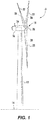
- FIG. 1 illustrates a perspective view of one embodiment of a wind turbine 10 that may implement the control technology according to the present disclosure is illustrated.
- the wind turbine 10 generally includes a tower 12 extending from a support surface 14, a nacelle 16 mounted on the tower 12, and a rotor 18 coupled to the nacelle 16.
- the rotor 18 includes a rotatable hub 20 and at least one rotor blade 22 coupled to and extending outwardly from the hub 20.
- the rotor 18 includes three rotor blades 22.
- the rotor 18 may include more or less than three rotor blades 22.
- Each rotor blade 22 may be spaced about the hub 20 to facilitate rotating the rotor 18 to enable kinetic energy to be transferred from the wind into usable mechanical energy, and subsequently, electrical energy.
- the hub 20 may be rotatably coupled to an electric generator 24 ( FIG. 2 ) positioned within the nacelle 16 to permit electrical energy to be produced.
- the wind turbine 10 may also include a wind turbine controller 26 centralized within the nacelle 16.
- the controller 26 may be located within any other component of the wind turbine 10 or at a location outside the wind turbine.
- the controller 26 may be communicatively coupled to any number of the components of the wind turbine 10 in order to control the operation of such components and/or to implement a correction action.
- the controller 26 may include a computer or other suitable processing unit.
- the controller 26 may include suitable computer-readable instructions that, when implemented, configure the controller 26 to perform various different functions, such as receiving, transmitting and/or executing wind turbine control signals.
- the generator 24 may be coupled to the rotor 18 for producing electrical power from the rotational energy generated by the rotor 18.
- the rotor 18 may include a rotor shaft 34 coupled to the hub 20 for rotation therewith.
- the rotor shaft 34 may, in turn, be rotatably coupled to a generator shaft 36 of the generator 24 through a gearbox 38.
- the rotor shaft 34 may provide a low speed, high torque input to the gearbox 38 in response to rotation of the rotor blades 22 and the hub 20.
- the gearbox 38 may then be configured to convert the low speed, high torque input to a high speed, low torque output to drive the generator shaft 36 and, thus, the generator 24.
- Each rotor blade 22 may also include a pitch adjustment mechanism 32 configured to rotate each rotor blade 22 about its pitch axis 28.
- each pitch adjustment mechanism 32 may include a pitch drive motor 40 (e.g., any suitable electric, hydraulic, or pneumatic motor), a pitch drive gearbox 42, and a pitch drive pinion 44.
- the pitch drive motor 40 may be coupled to the pitch drive gearbox 42 so that the pitch drive motor 40 imparts mechanical force to the pitch drive gearbox 42.
- the pitch drive gearbox 42 may be coupled to the pitch drive pinion 44 for rotation therewith.
- the pitch drive pinion 44 may, in turn, be in rotational engagement with a pitch bearing 46 coupled between the hub 20 and a corresponding rotor blade 22 such that rotation of the pitch drive pinion 44 causes rotation of the pitch bearing 46.
- rotation of the pitch drive motor 40 drives the pitch drive gearbox 42 and the pitch drive pinion 44, thereby rotating the pitch bearing 46 and the rotor blade 22 about the pitch axis 28.
- the wind turbine 10 may employ direct drive pitch or a separate pitch drive systems including hydraulics.
- the wind turbine 10 may include one or more yaw drive mechanisms 66 communicatively coupled to the controller 26, with each yaw drive mechanism(s) 66 being configured to change the angle of the nacelle 16 relative to the wind (e.g., by engaging a yaw bearing 68 of the wind turbine 10).
- the wind turbine 10 may also include one or more sensors 48, 50, 52 for measuring operating and/or loading conditions of the wind turbine 10.
- the sensors may include blade sensors 48 for measuring a pitch angle of one of the rotor blades 22 or for measuring a loading acting on one of the rotor blades 22; generator sensors 50 for monitoring the generator 24 (e.g. torque, speed, acceleration and/or the power output); and/or various wind sensors 52 for measuring various wind parameters, such as wind speed, wind peaks, wind turbulence, wind shear, changes in wind direction, air density, or similar.
- the sensors may be located near the ground of the wind turbine 10, on the nacelle 16, or on a meteorological mast of the wind turbine 10.
- the sensors may be Micro Inertial Measurement Units (MIMUs), strain gauges, accelerometers, pressure sensors, angle of attack sensors, vibration sensors, Light Detecting and Ranging (LIDAR) sensors, camera systems, fiber optic systems, anemometers, wind vanes, Sonic Detection and Ranging (SODAR) sensors, infra lasers, radiometers, pitot tubes, rawinsondes, other optical sensors, and/or any other suitable sensors.
- MIMUs Micro Inertial Measurement Units
- LIDAR Light Detecting and Ranging
- SODAR Sonic Detection and Ranging
- the various sensors may be configured to provide a direct measurement of the parameters being monitored or an indirect measurement of such parameters.
- the sensors may, for example, be used to generate signals relating to the parameter being monitored, which can then be utilized by the controller 26 to determine the actual parameter.
- the controller 26 may include one or more processor(s) 58, a wind turbine parameter estimator 56, and associated memory device(s) 60 configured to perform a variety of computer-implemented functions (e.g., performing the methods, steps, calculations and the like and storing relevant data as disclosed herein). Additionally, the controller 26 may also include a communications module 62 to facilitate communications between the controller 26 and the various components of the wind turbine 10.
- the communications module 62 may include a sensor interface 64 (e.g., one or more analog-to-digital converters) to permit signals transmitted from the sensors 48, 50, 52 to be converted into signals that can be understood and processed by the processors 58.
- the sensors 48, 50, 52 may be communicatively coupled to the communications module 62 using any suitable means.
- the sensors 48, 50, 52 are coupled to the sensor interface 64 via a wired connection.
- the sensors 48, 50, 52 may be coupled to the sensor interface 64 via a wireless connection, such as by using any suitable wireless communications protocol known in the art.
- processor refers not only to integrated circuits referred to in the art as being included in a computer, but also refers to a controller, a microcontroller, a microcomputer, a programmable logic controller (PLC), an application specific integrated circuit, a graphics processing unit (GPUs), and/or other programmable circuits now known or later developed.
- PLC programmable logic controller
- GPUs graphics processing unit
- the memory device(s) 60 may generally comprise memory element(s) including, but not limited to, computer readable medium (e.g., random access memory (RAM)), computer readable non-volatile medium (e.g., a flash memory), a floppy disk, a compact disc-read only memory (CD-ROM), a magneto-optical disk (MOD), a digital versatile disc (DVD) and/or other suitable memory elements.
- RAM random access memory
- computer readable non-volatile medium e.g., a flash memory
- CD-ROM compact disc-read only memory
- MOD magneto-optical disk
- DVD digital versatile disc
- Such memory device(s) 60 may generally be configured to store suitable computer-readable instructions that, when implemented by the processor(s) 58, configure the controller 26 to perform various functions as described herein.
- the processor 58 includes an inner control loop 70 and an outer control loop 72.
- the outer control loop 72 is configured to control the thrust set point 74 and the speed set point 76
- the inner control loop 70 is configured to provide multi-variable control 78 of pitch and torque based on the thrust and speed set points 74, 76.
- the inner control loop 70 utilizes the thrust set point 74 and the actual or measured thrust 93 to determine the desired change in thrust 73 in response to control actuations starting from an instantaneous operating point.
- the inner control loop 70 utilizes the speed set point 76 and the actual or measured speed 93 to determine the desired change in speed 75 in response to control actuations starting from the instantaneous operating point.
- speed of the wind turbine and variations thereof are representative of a generator speed, a rotor speed, a tip speed ratio, or similar.
- the thrust set point 74 may be adjusted via the outer control loop 72. For example, in one embodiment, when the wind turbine 10 is operating above a rated wind speed, the outer control loop 72 determines or controls the thrust set point 74 based on a filtered or averaged difference 84 between the actual power 82 and the desired power set point 80.
- the outer control loop 72 determines or controls the thrust set point 74 based on a filtered or averaged difference 90 between the actual pitch 88 and the optimal fine pitch setting 86.
- the outer control loop 72 may also include a switch 96 configured to alternate or proportionally ramp between control settings depending on the wind speed operating region.
- the thrust set point 74 and/or speed set point 76 can be scheduled as a function of estimated wind speed or determined by any other suitable means. It should be understood that the speed set point 76 may change as a function of wind speed, optimal tip speed ratio, speed limitations of the components, or similar.
- the outer control loop 72 may also include one or more proportional-integral-derivative (PID) controllers 95 or similar control loop feedback mechanisms configured to calculate an error based on the difference between a measured operating point (e.g. actual pitch 88 or actual power 82) and a desired operating point (e.g. optimal fine pitch 86 or power set point 80).
- PID controller(s) 95 is configured to minimize error in the outer control loop 72 by adjusting the operating points used as inputs to the inner control loop 70.
- the inner control loop 70 may also include a multi-variable control 78 or multi-objective optimization framework.
- the multi-variable control 78 utilizes the desired changes 73, 75 in thrust and speed to determine both pitch and torque set points 92, 94 or any other suitable actuations.
- the multi-variable control 78 of pitch and torque actuations 92, 94 in real-time differs from conventional wind turbine control where it is common to separate such actuations according to an operating region.
- the multi-variable control 78 may include linear and non-linear control approaches such as: a) Sliding Mode Control (SMC) strategies, b) H-infinity controls, c) linear-quadratic-Gaussian (LQG)/H-2 controls (shown to be equivalent), d) a mixed H-2/H-infinity approach or combination of b) and c) above, or e) a Linear Parameter Varying (LPV).
- SMC Sliding Mode Control
- H-infinity controls H-infinity controls
- LQG/H-2 controls shown to be equivalent
- a mixed H-2/H-infinity approach or combination of b) and c) above or e) a Linear Parameter Varying (LPV).
- LDV Linear Parameter Varying
- the SMC strategies in various embodiments, is characterized in that a control action that is discontinuous across a desired trajectory of the controlled parameters achieves a motion along the trajectory, and in that fashion, is able to guarantee observance of
- the H-infinity controls shape the induced L-2 norm of the system (i.e. bounded input energy to bounded output energy or otherwise, or worst case effect on output energy due to bounded energy input) that is achieved by suitable frequency domain shaping weights on input and output signals as well as the open loop transfer function.
- the LQG/H-2 controls in particular embodiments, minimize the systems output variance to a white noise input, achieved by suitable frequency domain shaping weights on input and output signals.
- the LPV control in certain embodiments, is characterized by the model of the system depending linearly on a measurable operating parameter of the wind turbine, thereby providing the capability of continuously changing the control actions as a function of its value, among other advanced control strategies.
- the adjustments based on optimal fine pitch 86 (below rated wind speed) and actual power output 82 (above rated wind speed) effectively low-pass filter the raw fluctuations of the pitch and torque set points 92, 94 coming from the inner control loop 70, i.e. from plant 98.
- the thrust set point 74 changes in response to long-term fluctuations in wind speed, but not in response to each short wind gust.
- the controller 26 filters and rejects the thrust variations from higher frequency turbulence.
- the source of the thrust set point 74 for the inner control loop 70 is the subject matter of the outer control loop 72
- the source of the speed set point 76 may be similar to conventional methods known in the art.
- the actual speed 93 and the actual thrust 91 values (which are used as inputs to the inner control loop 70) can be determined via one or more sensors, e.g. 48, 50, 52, or the wind parameter estimator 56 as described below.
- the thrust input may be a directly-measured quantity.
- the thrust input may be an indirect measurement early in the load parth that is indicative of thrust, such as individual or collective blade out-of-plane bending, individual or collective flap-wise blade bending, individual or collective movement in the main shaft flange sensors (such as those described in U.S. Patent Number 7,160,083 entitled, "Method and Apparatus for Wind Turbine Rotor Load Control” filed on February 3, 2003 and incorporated herein by reference), or any other suitable proxy for estimating and/or determining thrust.
- the thrust may be determined by sensors or estimated by a computer model.
- the sensor measurements may be filtered, calibrated, and/or checked for plausibility against the estimated thrust as determined by the computer model, while responding in raw form earlier and with higher frequency bandwidth than the estimated thrust, which is effectively low-pass filtered by the rotor inertia.
- the actual speed 93 and the actual thrust 91 inputs can be measured values from the control transducers.
- the wind turbine parameter estimator 56 is configured to receive the signals from one or more sensors that are representative of various operating and/or loading conditions of the wind turbine 10.
- the operating conditions may consist of any combination of the following: a wind speed, a pitch angle, a generator speed, a power output, a torque output, a temperature, a pressure, a tip speed ratio, an air density, a rotor speed, a power coefficient, a torque coefficient, a thrust coefficient, a thrust, a thrust response, a blade bending moment, a shaft bending moment, a tower bending moment, a speed response, or similar.
- the wind turbine parameter estimator 56 may be considered software that utilizes the operating and/or loading conditions to calculate, in real-time, the speed and/or thrust response as described herein.
- the wind turbine parameter estimator 56 may include firmware that includes the software, which may be executed by the processor 58.
- the wind turbine parameter estimator 56 is configured to implement a control algorithm having a series of equations to determine the actual speed 93 and/or the actual thrust 91. As such, the equations are solved using the one or more operating conditions, one or more aerodynamic performance maps, one or more look-up tables (LUTs), or any combination thereof.
- the aerodynamic performance maps are dimensional or non-dimensional tables that describe rotor loading and performance (e.g.
- the aerodynamic performance maps may include: a power coefficient, a thrust coefficient, a torque coefficient, and/or partial derivatives with respect to pitch angle, rotor speed, or tip speed ratio.
- the aerodynamic performance maps can be dimensional power, thrust, and/or torque values instead of coefficients.
- the LUTs may include: aerodynamic performance parameters, blade bending load, tower bending load, shaft bending load, or any other turbine component load.
- one embodiment of the multi-variable control 78 estimates gradients of two surfaces 83, 85 based on the instantaneous operating point, LUTs, and/or calculations. Further, the gradients represent sensitivities of thrust and speed to one or more pitch and torque actuations. Such sensitivities are used to to determine one or more parameter set points (e.g. pitch set point 92 and torque set point 94). For example, referring particularly to FIG.
- each of the illustrated surfaces 83, 85 surround an operating point 81 on an aerodynamic performance map of the rotor 18 and extend some distance from the operating point 81 in the pitch direction (y-axis) and some distance in the torque direction (x-axis), which may be closely related to, e.g. inverse, but not synonymous with the tip speed ratio (TSR) direction on the aerodynamic performance maps.
- the surfaces 83, 85 are planes effectively linearized at the operating point 81 of the wind turbine 10.
- the surfaces 83, 85 may also be constructed having curvature.
- the x-axis and the y-axis represent the torque set point 94 and the pitch set point 92, respectively, or the change therein and the z-axis represents either the thrust or speed set responses for one surface 83, 85 or the other.
- the x- and y- axes may be constructed either in terms of absolute torque and pitch set points or relative torque and pitch set points.
- the graphs of FIGS. 5-10 are representative of one or more operating regions for the wind turbine 10.
- six different operating regions are evaluated, namely, a low wind speed operating region ( FIG. 5 ), a slightly below rated wind speed operating region ( FIG. 6 ), a rated wind speed operating region ( FIG. 7 ), a slightly above rated wind speed operating region ( FIG. 8 ), a well above rated wind speed operating region ( FIG. 9 ), and a high or cut-out wind speed operating region ( FIG. 10 ).
- any number of operating regions may be evaluated including more than six or less than six and the calculation of surfaces about the operating point can take place during each control cycle, effectively covering continuously the entire operating space.
- Each operating region includes an operating point 81.
- the operating point 81 corresponds to a particular wind speed, a tip speed ratio, and a pitch angle.
- the operating point 81 may include any operational point of the wind turbine 10, including, but not limited to a wind speed, a pitch angle, a generator speed, a power output, a torque output, a tip speed ratio, a rotor speed, a power coefficient, a torque coefficient, a thrust coefficient, a thrust, a thrust response, a blade bending moment, a shaft bending moment, a tower bending moment, a speed response, or similar.
- the operating point 81 may be any dimensional or non-dimensional parameter representative of an operating set point of the wind turbine 10. More specifically, for above rated wind speeds, the operating point 81 corresponds to a filtered or average power output 84, whereas for below rated wind speeds, the operating point 81 corresponds to a filtered or average fine pitch 90.
- the controller 26 operates the wind turbine 10 based on the operating point 81 and determines corresponding gradients of the thrust and speed represented by surfaces 83 and 85, respectively.
- the slopes of the planes of the surfaces 83, 85 are the partial derivatives of the thrust or speed with respect to pitch or resisting torque.
- Equations 1 through 6 may be determined using from one or more look-up tables (LUTs), e.g. C M , stored within the controller 26 as indicated by the term "lookup" in the equations above.
- LUTs look-up tables
- the graphs illustrate the normalized, potential thrust and speed responses of the plant 98 as functions of pitch and torque around the various operating points 81.
- FIGS. 5-10 illustrate gradient directions for each surface 83, 85 superimposed on the response surfaces in bold lines.
- FIGS. 5-10 provide a visual representation of thrust-speed control
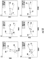
- the graphs of FIGS. 11 and 12 illustrate gradient directions and inverse slopes for purposes of visualization and design. More specifically, FIG. 11 illustrates a set of six plots that present the same information depicted in FIGS. 5-10 in a more compact and user-friendly form.
- the plots illustrate vectors in the directions of the thrust and speed gradients 83, 85 on the pitch-torque surface for each operating region.
- the length of each vector is the actuation required to compensate a predetermined step in wind speed, e.g. 1 m/s, at each operating point 81, thus relating the partial derivatives with respect to wind speed.
- the controller 26 may generate plots corresponding to the step responses necessary to compensate a change in wind speed, e.g. a 10% change in wind speed, or any other suitable proportionality.
- sensitivities may be linear or linearized; however, it should be understood by those of ordinary skill in the art that there is likely some nonlinearity in all regions and such nonlinearity may be included directly or otherwise accounted or corrected for in certain embodiments.
- the thrust and speed sensitivity surfaces 83, 85 for low wind speeds are illustrated. As shown, the surfaces 83, 85 are sloped in different directions at low wind speeds.
- the sensitivities in thrust and speed with the least actuations, i.e. the gradients of the surfaces 83, 85, are nearly perpendicular on the pitch-torque domain (as shown by the bold line of FIG. 5 ), with pitch primarily affecting thrust and torque primarily affecting speed.
- the near-perpendicular gradients are desirable and indicate that the actuation for thrust and speed may be controlled nearly independent of each other.
- thrust-speed control provides a reduction in fatigue loads while also regulating rotor speed, while pitch may vary slightly around what is considered optimal for power production.
- degree to which pitch deviates from the quasi-static aerodynamic optimum may be chosen by selection of filtering and/or gains in the outer control loop 72 as well as by imposition of limitations, striking a balance between desired fatigue reduction, and/or close adherence to the quasi-static aerodynamic optimum pitch.
- FIG. 6 illustrates the thrust and speed response surfaces 83, 85 for wind speeds at slightly below rated wind speed, e.g. typically around 4 to 8 m/s.
- thrust-speed control is capable of regulating the thrust precisely and simultaneously with rotor speed. Further, the potential fatigue benefit at this wind speed increases when compared to the benefit at lower wind speeds since both the rotor thrust and variations therein are greater than at lower wind speeds.
- FIG. 11(B) illustrates the corresponding thrust-speed vector on the pitch-torque domain for the operating region. As shown, the thrust-speed vector is similar to the vector of 11(A), though the gradients of the surfaces 83, 85 are less perpendicular on the pitch-torque domain.
- the controller 26 is also capable of regulating thrust precisely and simultaneously with speed, similar to slightly below rated wind speed.
- Rated wind speeds vary per wind turbine, but typically range from about 8 m/s to about 15 m/s.
- the thrust and speed response surfaces 83, 85 can be controlled virtually independent of each other.
- FIG. 11(C) illustrates the corresponding thrust-speed vector on the pitch-torque domain for the operating region. Accordingly, the largest opportunity for a reduction in fatigue loads is typically seen at this operating range, since the average thrust is high and potential variations in the thrust are correspondingly large. Further, as shown in FIG.
- the thrust-speed vector is similar to the vector of FIG. 11 (B) .
- the thrust set point 74 may saturate at a maximum value or schedule of maximum values, including but not limited a value or values derived from the maximum loads on hardware components of the turbine in certain wind conditions or design load cases.
- the controller 26 may allow a change in thrust in order to keep speed within predetermined bounds or may accept a transient change in speed to maintain steady a thrust.
- line 102 represents a typical or predominant direction of an actuation (i.e. a change in the operating point) for a given operating region. More specifically, in one embodiment, line 102 may represent an optimal direction of the actuation as long as it holds similarly when the wind turbine 10 is slightly off to any side of the operating point.
- the controller 26 is configured to follow each surface 83, 85 to the level of each individually optimal (for thrust or speed) response step. As such, the controller 26 can obtain the correct result at any point that is on a level with the response step (offset perpendicular to its direction), though anything other than the direction of the response step will require more from the actuators to achieve such control.
- FIG. 11 (A-F) represent the points on the response surfaces that will give an ideal result for individual metrics (e.g. thrust, speed) at their respective operating point. Further, the point where the dashed lines intersect in FIG. 12 (A-F) represents the point where both speed and thrust may be simultaneously controlled. As the individual-ideal steps become more closely aligned in direction, but remain different in size, the control actuation to simultaneously meet both objectives may become very large and/or out of alignment with the ideal direction for either. For example, such is the case where prioritization between the thrust and speed regulation objectives may take place in various embodiments, where constraints may be imposed to stay within the realistic limits and responses of the actuators.
- prioritization between the thrust and speed regulation objectives may take place in various embodiments, where constraints may be imposed to stay within the realistic limits and responses of the actuators.
- the controller 26 can visualize the alignment of the two control objectives and whether simultaneously control for thrust and speed in any operating region is realistic. Further, in various embodiments, the controller 26 may be required to determine and/or prioritize whether to regulate speed or thrust regulation, e.g. where the two gradients approach either perfect alignment with different magnitude or where they approach perfect opposite directions in the pitch-torque plane for a given rotor 18. For example, as shown in FIG. 12 , graphs (E) and (F) illustrate the two response steps approaching perfect directional alignment with differing magnitude. As shown, the step required to satisfy both speed and thrust tends to be increasingly off to one side or the other of the ideal steps for either thrust or speed regulation.
- the controller 26 is configured to constantly control the wind turbine 10 in order to prioritize either speed or thrust and provide realistic actuation demands.
- the controller 26 is configured to determine and/or calculate a limitation on the step in order to avoid wasted control efforts.
- a boundary proportional to the angle or half angle between the thrust gradient and speed gradient may be utilized such that the overall response is constrained within a predetermined directional range from the best ratio of desired effect per unit actuation.
- the operating point may be determined from any one or more conditions or states of the wind turbine 10, including, but not limited to pitch angle 90 or a power output 84.
- the operating point may include any of the following operational parameters including, but not limited to a wind speed, a pitch angle, a generator speed, a power output, a torque output, a tip speed ratio, a rotor speed, a power coefficient, a torque coefficient, a thrust, a thrust coefficient, a blade bending moment (including out-of-plane and flap-wise blade bending moments), a shaft bending moment, a tower bending moment, a speed response, or similar.
- operational parameters including, but not limited to a wind speed, a pitch angle, a generator speed, a power output, a torque output, a tip speed ratio, a rotor speed, a power coefficient, a torque coefficient, a thrust, a thrust coefficient, a blade bending moment (including out-of-plane and flap-wise blade bending moments), a shaft bending moment, a tower bending moment, a speed response, or similar.
- the method 200 includes a first step 202 of operating the wind turbine based on a thrust set point and a speed set point.
- Another step 204 includes determining a desired change in actual speed of the wind turbine in response to control actuations starting from an instantaneous operating point.
- the method 200 also includes a step of determining a desired change in actual thrust of the wind turbine in response to control actuations starting from an instantaneous operating point (step 206).
- the step of determining the desired changes in actual speed and thrust may include taking the difference between the actual thrust or speed and the desired thrust or speed set points and filtering and/or averaging the differences, respectively.
- a next step 208 includes determining at least one parameter set point that will achieve the desired change in actual speed and the desired change in actual thrust and thrust and speed sensitivities.
- the parameter set point(s) includes a pitch set point 92 and a torque set point 94.
- the method 200 includes a step 210 of controlling the wind turbine based on the parameter set point(s) so as to so as to maintain the actual thrust and the actual speed of the wind turbine within a certain tolerance of the thrust set point and the speed set point, thereby regulating loads acting on the wind turbine.
Claims (12)
- Verfahren (200) zum dynamischen Steuern einer Windturbine (10), wobei das Verfahren (200) umfasst:Betreiben der Windturbine (10) auf der Basis eines Druckkraft-Einstellpunktes (74) und eines Drehzahl-Einstellpunktes (76);über einen Prozessor, Bestimmen einer gewünschten Änderung in der tatsächlichen Drehzahl (73) der Windturbine (10) als Reaktion auf Steuerungsmaßnahmen, die von einem momentanen Betriebspunkt beginnen;über den Prozessor, Bestimmen einer gewünschten Änderung in der tatsächlichen Druckkraft (75) der Windturbine (10) als Reaktion auf Steuerungsmaßnahmen, die vom momentanen Betriebspunkt (81) beginnen;über den Prozessor, Bestimmen von mindestens einem Parameter- Einstellpunkt, der die gewünschte Änderung in der tatsächlichen Drehzahl (73) und die gewünschte Änderung in der tatsächlichen Druckkraft (75) erreicht; undSteuern der Windturbine (10) auf der Basis des Parameter-Einstellpunktes, um so die tatsächliche Druckkraft und die tatsächliche Drehzahl der Windturbine (10) innerhalb einer bestimmten Toleranz des Druckkraft-Einstellpunktes (74) und des Drehzahl-Einstellpunktes (76) zu halten, wodurch die Belastungen, die auf die Windturbine (10) wirken, reguliert werden;dadurch gekennzeichnet, dass in Betriebsbereichen, wenn eine Windgeschwindigkeit oberhalb einer bemessenen Windgeschwindigkeit liegt, der Druckkraft-Einstellpunkt (74) gemäß einer gefilterten oder ungefilterten Leistungsabgabe eingestellt wird, wobei, wenn die Windgeschwindigkeit unter der bemessenen Windgeschwindigkeit liegt, der Druckkraft-Einstellpunkt (74) gemäß eines gefilterten oder ungefilterten Anstellwinkels eingestellt wird, und wobei, wenn die Windgeschwindigkeit bei oder in der Nähe der bemessenen Windgeschwindigkeit ist, der Druckkraft-Einstellpunkt (74) auf der Basis einer maximalen Konstruktions-Druckkraft der Windturbine (10) eingestellt wird.
- Verfahren (200) nach Anspruch 1, wobei der momentane Betriebspunkt (81) mindestens ein Element aus einer Windgeschwindigkeit, einem Anstellwinkel, einer Generatordrehzahl, einer Leistungsabgabe, einer Drehmomentabgabe, einer Schnelllaufzahl, einer Rotordrehzahl, einem Leistungskoeffizienten, einem Drehmomentkoeffizienten, einer Druckkraft, einem Druckkraft-Koeffizienten, einer Schubantwort, einem Blatt Biegemoment, einem Wellenbiegemoment, einer Geschwindigkeitsreaktion oder einem Turmbiegemoment umfasst.
- Verfahren (200) nach einem der vorherigen Ansprüche, das ferner das Einstellen von mindestens einem Element aus dem Druckkraft-Einstellpunkt (74) oder dem Drehzahl-Einstellpunkt (76) auf der Basis des momentanen Betriebspunktes (81) umfasst.
- Verfahren (200) nach einem der vorherigen Ansprüche, das ferner das Bestimmen einer gewünschten Änderung in der Leistungsabgabe (84) auf der Basis einer Differenz zwischen einer tatsächlichen Leistung (82) und einem Leistungs-Einstellpunkt (80) und das Bestimmen einer gewünschten Änderung im Anstellwinkel (90) auf der Basis einer Differenz zwischen einer tatsächlichen Blattstellung (88) und einer optimalen feinen Blattstellung (86) umfasst.
- Verfahren (200) nach einem der vorherigen Ansprüche, das ferner das Bestimmen der gewünschten Änderung in der tatsächlichen Drehzahl (75) umfasst durch:Bestimmen einer tatsächlichen Drehzahl (93) der Windturbine (10); undBestimmen einer Differenz zwischen dem Drehzahl-Einstellpunkt (76) und der tatsächlichen Drehzahl (93), wobei sowohl der Drehzahl-Einstellpunkt (76) als auch die tatsächliche Drehzahl (93) eine Generatordrehzahl, eine Rotordrehzahl oder eine Schnelllaufzahl berücksichtigen.
- Verfahren (200) nach einem der vorherigen Ansprüche, das ferner das Bestimmen der gewünschten Änderung in der tatsächlichen Druckkraft (73) umfasst durch:Bestimmen einer tatsächlichen Druckkraft (91) der Windturbine (10); undBestimmen einer Differenz zwischen dem Druckkraft-Einstellpunkt (74) und der tatsächlichen Druckkraft (91).
- Verfahren (200) nach Anspruch 6, wobei das Bestimmen der tatsächlichen Druckkraft (91) ferner das Nutzen von mindestens einem Element der folgenden umfasst: ein oder mehr Sensoren, mehrere Gleichungen, ein oder mehr aerodynamische Karten oder ein oder mehr Verweistabellen.
- Verfahren (200) nach einem der vorherigen Ansprüche, wobei das Bestimmen des Parameter-Einstellpunktes ferner das Nutzen einer Mehrgrößenregelung (78) umfasst.
- Verfahren (200) nach Anspruch 8, wobei die Mehrgrößenregelung (78) mindestens ein Element aus einer Kostenfunktion, einer Verlustfunktion oder einer Übertragungsfunktion umfasst.
- Verfahren (200) nach Anspruch 8 oder 9, das ferner das Bestimmen einer Drehzahlempfindlichkeit und einer Druckkraft-Empfindlichkeit durch Berechnen von mindestens einer ersten Ableitung der tatsächlichen Druckkraft oder der tatsächlichen Drehzahl in Bezug auf den Betriebspunkt und eine oder mehr Kontrollbetätigungen und die Nutzung der Drehzahlempfindlichkeit und der Druckkraft-Empfindlichkeit in der Mehrgrößenregelung umfasst.
- Verfahren (200) nach einem der vorherigen Ansprüche, wobei der Parameter-Einstellpunkt ferner mindestens ein Element aus einem Anstellwinkel-Einstellpunkt (92) oder einem Drehmoment-Einstellpunkt (94) umfasst.
- System zur dynamischen Steuerung einer Windturbine (10), wobei das System umfasst:einen Prozessor (58), der für Folgendes ausgelegt ist:Betreiben der Windturbine (10) auf der Basis eines gewünschten Druckkraft-Einstellpunktes (74) und eines gewünschten Drehzahl-Einstellpunktes (76);Bestimmen einer gewünschten Änderung in der tatsächlichen Drehzahl (75) der Windturbine (10) als Reaktion auf Kontrollaufschaltungen, die von einem momentanen Betriebspunkt (81) starten;Bestimmen einer gewünschten Änderung in der tatsächlichen Druckkraft (73) der Windturbine (10) als Reaktion auf Kontrollaufschaltungen, die von einem momentanen Betriebspunkt (81) starten;Bestimmen von mindestens einem Parameter-Einstellpunkt, der die gewünschte Änderung in der tatsächlichen Drehzahl (75) und die gewünschte Änderung in der tatsächlichen Druckkraft (73) erreicht; undeinen Controller (26), der kommunikativ mit dem Prozessor (58) verbunden ist, wobei der Controller (26) dafür ausgelegt ist, die Windturbine (10) auf der Basis des Parameter-Einstellpunktes zu steuern, um so die tatsächliche Druckkraft und die tatsächliche Drehzahl der Windturbine (10) innerhalb einer bestimmten Toleranz des Druckkraft-Einstellpunktes (74) und des Drehzahl-Einstellpunktes (76) zu halten, wodurch die Belastungen, die auf die Windturbine (10) wirken, reguliert werden;dadurch gekennzeichnet, dass in Betriebsbereichen, wenn eine Windgeschwindigkeit oberhalb einer bemessenen Windgeschwindigkeit liegt, der Druckkraft-Einstellpunkt (74) gemäß einer gefilterten oder ungefilterten Leistungsabgabe eingestellt wird, wobei, wenn die Windgeschwindigkeit unter der bemessenen Windgeschwindigkeit liegt, der Druckkraft-Einstellpunkt (74) gemäß eines gefilterten oder ungefilterten Anstellwinkels eingestellt wird, und wobei, wenn die Windgeschwindigkeit bei oder in der Nähe der bemessenen Windgeschwindigkeit ist, der Druckkraft-Einstellpunkt (74) auf der Basis einer maximalen Konstruktions-Druckkraft der Windturbine (10) eingestellt wird.
Applications Claiming Priority (1)
| Application Number | Priority Date | Filing Date | Title |
|---|---|---|---|
| US14/251,879 US9631606B2 (en) | 2014-04-14 | 2014-04-14 | System and method for thrust-speed control of a wind turbine |
Publications (2)
| Publication Number | Publication Date |
|---|---|
| EP2933477A1 EP2933477A1 (de) | 2015-10-21 |
| EP2933477B1 true EP2933477B1 (de) | 2018-03-07 |
Family
ID=53054853
Family Applications (1)
| Application Number | Title | Priority Date | Filing Date |
|---|---|---|---|
| EP15160454.3A Active EP2933477B1 (de) | 2014-04-14 | 2015-03-24 | SYSTEM UND VERFAHREN ZUR Steuerung DER SCHUBKRAFT und der GESCHWINDIGKEIT EINER WINDTURBINE |
Country Status (7)
| Country | Link |
|---|---|
| US (1) | US9631606B2 (de) |
| EP (1) | EP2933477B1 (de) |
| CN (1) | CN104976056B (de) |
| BR (1) | BR102015008181B1 (de) |
| CA (1) | CA2887089C (de) |
| DK (1) | DK2933477T3 (de) |
| ES (1) | ES2664825T3 (de) |
Cited By (1)
| Publication number | Priority date | Publication date | Assignee | Title |
|---|---|---|---|---|
| DE102018129622A1 (de) * | 2018-11-23 | 2020-05-28 | Wobben Properties Gmbh | Reglerstruktur und Regelverfahren für eine Windenergieanlage |
Families Citing this family (23)
| Publication number | Priority date | Publication date | Assignee | Title |
|---|---|---|---|---|
| CN103562709A (zh) * | 2011-04-28 | 2014-02-05 | 维斯塔斯风力系统集团公司 | 用于保护风力涡轮机不受极端事件影响的方法和装置 |
| CN106460792A (zh) * | 2014-06-20 | 2017-02-22 | 米塔科技有限公司 | 用于风力涡轮机推力限制的系统 |
| CN106415003A (zh) * | 2014-06-20 | 2017-02-15 | 米塔科技有限公司 | 动态螺距控制系统 |
| CN107630793B (zh) | 2016-07-18 | 2018-11-20 | 北京金风科创风电设备有限公司 | 风机齿形带或变桨轴承疲劳状态的检测方法、装置及系统 |
| CN108131245B (zh) * | 2016-12-01 | 2020-01-31 | 北京金风科创风电设备有限公司 | 风力发电机的恒功率运行控制方法和装置 |
| US10215157B2 (en) * | 2017-01-04 | 2019-02-26 | General Electric Company | Methods for controlling wind turbine with thrust control twist compensation |
| US10604268B2 (en) * | 2017-02-22 | 2020-03-31 | Pratt & Whitney Canada Corp. | Autothrottle control for turboprop engines |
| US10451036B2 (en) * | 2017-05-05 | 2019-10-22 | General Electric Company | Adjustment factor for aerodynamic performance map |
| US10634121B2 (en) | 2017-06-15 | 2020-04-28 | General Electric Company | Variable rated speed control in partial load operation of a wind turbine |
| US10598148B2 (en) * | 2017-08-22 | 2020-03-24 | General Electric Company | System for controlling a yaw drive of a wind turbine when a native yaw drive control system is non-operational |
| US10808681B2 (en) * | 2018-01-23 | 2020-10-20 | General Electric Company | Twist correction factor for aerodynamic performance map used in wind turbine control |
| ES2920139T3 (es) | 2018-08-20 | 2022-08-01 | Vestas Wind Sys As | Control de un aerogenerador |
| EP3647587A1 (de) * | 2018-11-01 | 2020-05-06 | Wobben Properties GmbH | Verfahren zum steuern einer windturbine und entsprechende windturbine |
| DE102018009334A1 (de) | 2018-11-28 | 2020-05-28 | Senvion Gmbh | Verfahren zum Betrieb einer Windenergieanlage, Windenergieanlage und Computerprogrammprodukt |
| CN109899231A (zh) * | 2019-02-26 | 2019-06-18 | 泗阳高传电机制造有限公司 | 一种风电机组变桨系统 |
| CN111472931B (zh) * | 2020-04-01 | 2021-07-30 | 上海电气风电集团股份有限公司 | 风力发电机及其控制方法和装置、计算机可读存储介质 |
| CN111577540B (zh) * | 2020-04-10 | 2022-03-29 | 东方电气风电股份有限公司 | 一种风力发电机组等效气动模型实现方法 |
| US11199175B1 (en) | 2020-11-09 | 2021-12-14 | General Electric Company | Method and system for determining and tracking the top pivot point of a wind turbine tower |
| US11421653B2 (en) * | 2020-11-13 | 2022-08-23 | General Electric Renovables Espana, S.L. | Systems and methods for multivariable control of a power generating system |
| US11408396B2 (en) | 2021-01-08 | 2022-08-09 | General Electric Renovables Espana, S.L. | Thrust control for wind turbines using active sensing of wind turbulence |
| US11703033B2 (en) | 2021-04-13 | 2023-07-18 | General Electric Company | Method and system for determining yaw heading of a wind turbine |
| KR102519428B1 (ko) * | 2021-08-02 | 2023-04-11 | 한밭대학교 산학협력단 | 정격풍속 이상에서 윈드쉬어에 의한 풍력터빈의 추력 동하중 모델링 방법 및 시스템 |
| US11536250B1 (en) | 2021-08-16 | 2022-12-27 | General Electric Company | System and method for controlling a wind turbine |
Family Cites Families (73)
| Publication number | Priority date | Publication date | Assignee | Title |
|---|---|---|---|---|
| US5155375A (en) * | 1991-09-19 | 1992-10-13 | U.S. Windpower, Inc. | Speed control system for a variable speed wind turbine |
| US5652485A (en) | 1995-02-06 | 1997-07-29 | The United States Of America As Represented By The Administrator Of The U.S. Environmental Protection Agency | Fuzzy logic integrated electrical control to improve variable speed wind turbine efficiency and performance |
| US6888262B2 (en) | 2003-02-03 | 2005-05-03 | General Electric Company | Method and apparatus for wind turbine rotor load control |
| US7004724B2 (en) | 2003-02-03 | 2006-02-28 | General Electric Company | Method and apparatus for wind turbine rotor load control based on shaft radial displacement |
| US7160083B2 (en) | 2003-02-03 | 2007-01-09 | General Electric Company | Method and apparatus for wind turbine rotor load control |
| GB2398841A (en) | 2003-02-28 | 2004-09-01 | Qinetiq Ltd | Wind turbine control having a Lidar wind speed measurement apparatus |
| JP4105036B2 (ja) | 2003-05-28 | 2008-06-18 | 信越化学工業株式会社 | レジスト下層膜材料ならびにパターン形成方法 |
| US7175389B2 (en) | 2004-06-30 | 2007-02-13 | General Electric Company | Methods and apparatus for reducing peak wind turbine loads |
| US7822560B2 (en) | 2004-12-23 | 2010-10-26 | General Electric Company | Methods and apparatuses for wind turbine fatigue load measurement and assessment |
| US8649911B2 (en) | 2005-06-03 | 2014-02-11 | General Electric Company | System and method for operating a wind farm under high wind speed conditions |
| US7476985B2 (en) | 2005-07-22 | 2009-01-13 | Gamesa Innovation & Technology, S.L. | Method of operating a wind turbine |
| US7351033B2 (en) * | 2005-09-09 | 2008-04-01 | Mcnerney Gerald | Wind turbine load control method |
| US7342323B2 (en) | 2005-09-30 | 2008-03-11 | General Electric Company | System and method for upwind speed based control of a wind turbine |
| US7613548B2 (en) | 2006-01-26 | 2009-11-03 | General Electric Company | Systems and methods for controlling a ramp rate of a wind farm |
| US7346462B2 (en) | 2006-03-29 | 2008-03-18 | General Electric Company | System, method, and article of manufacture for determining parameter values associated with an electrical grid |
| US7505833B2 (en) | 2006-03-29 | 2009-03-17 | General Electric Company | System, method, and article of manufacture for controlling operation of an electrical power generation system |
| ES2288121B1 (es) | 2006-05-31 | 2008-10-16 | GAMESA INNOVATION & TECHNOLOGY, S.L. | Metodo de operacion de un aerogenerador. |
| US7883317B2 (en) | 2007-02-02 | 2011-02-08 | General Electric Company | Method for optimizing the operation of a wind turbine |
| US9020650B2 (en) | 2007-02-13 | 2015-04-28 | General Electric Company | Utility grid, controller, and method for controlling the power generation in a utility grid |
| WO2008124185A1 (en) | 2007-04-09 | 2008-10-16 | Live Data Systems, Inc. | System and method for monitoring and managing energy performance |
| CN101680426B (zh) | 2007-04-30 | 2013-08-14 | 维斯塔斯风力系统有限公司 | 风力涡轮机的工作方法、风力涡轮机以及风力涡轮机组 |
| US7950901B2 (en) | 2007-08-13 | 2011-05-31 | General Electric Company | System and method for loads reduction in a horizontal-axis wind turbine using upwind information |
| WO2009027509A1 (en) | 2007-08-31 | 2009-03-05 | Vestas Wind Systems A/S | Wind turbine siting and maintenance prediction |
| US20090099702A1 (en) | 2007-10-16 | 2009-04-16 | General Electric Company | System and method for optimizing wake interaction between wind turbines |
| US7573149B2 (en) | 2007-12-06 | 2009-08-11 | General Electric Company | System and method for controlling a wind power plant |
| US7861583B2 (en) | 2008-01-17 | 2011-01-04 | General Electric Company | Wind turbine anemometry compensation |
| JP5033033B2 (ja) | 2008-03-27 | 2012-09-26 | 富士重工業株式会社 | 水平軸風車の乱流強度計測方法 |
| EP2110551B2 (de) * | 2008-04-15 | 2019-02-27 | Siemens Aktiengesellschaft | Verfahren und Vorrichtung zur auf Vorhersage basierten Windturbinensteuerung |
| US7942629B2 (en) | 2008-04-22 | 2011-05-17 | General Electric Company | Systems and methods involving wind turbine towers for power applications |
| US8093737B2 (en) | 2008-05-29 | 2012-01-10 | General Electric Company | Method for increasing energy capture in a wind turbine |
| US8050899B2 (en) | 2008-05-30 | 2011-11-01 | General Electric Company | Method for wind turbine placement in a wind power plant |
| US8262354B2 (en) | 2008-08-27 | 2012-09-11 | General Electric Company | Method and apparatus for load measurement in a wind turbine |
| CN101684774B (zh) | 2008-09-28 | 2012-12-26 | 通用电气公司 | 一种风力发电系统及风力发电机的测风方法 |
| GB2466433B (en) | 2008-12-16 | 2011-05-25 | Vestas Wind Sys As | Turbulence sensor and blade condition sensor system |
| US8050887B2 (en) | 2008-12-22 | 2011-11-01 | General Electric Company | Method and system for determining a potential for icing on a wind turbine blade |
| US8380357B2 (en) | 2009-03-23 | 2013-02-19 | Acciona Windpower, S.A. | Wind turbine control |
| GB2471060A (en) | 2009-03-24 | 2010-12-22 | Ralph-Peter Steven Bailey | Automatic pitch control for horizontal axis wind turbines |
| US8441138B2 (en) | 2009-05-07 | 2013-05-14 | Vestas Wind Systems A/S | Wind turbine |
| GB2472437A (en) | 2009-08-06 | 2011-02-09 | Vestas Wind Sys As | Wind turbine rotor blade control based on detecting turbulence |
| US8328514B2 (en) | 2009-09-11 | 2012-12-11 | General Electric Company | System and methods for determining a monitor set point limit for a wind turbine |
| EP2302207A1 (de) | 2009-09-23 | 2011-03-30 | Siemens Aktiengesellschaft | Laststeuerung von Energieerzeugungsmaschinen basierend auf der abgelaufenen Ermüdungslebensdauer und der Echtzeit des Betriebs einer Strukturkomponente |
| US7772713B2 (en) * | 2009-09-30 | 2010-08-10 | General Electric Company | Method and system for controlling a wind turbine |
| US8025476B2 (en) | 2009-09-30 | 2011-09-27 | General Electric Company | System and methods for controlling a wind turbine |
| DK201070274A (en) * | 2009-10-08 | 2011-04-09 | Vestas Wind Sys As | Control method for a wind turbine |
| US20110153096A1 (en) | 2009-12-22 | 2011-06-23 | Sujan Kumar Pal | Method and system for monitoring operation of a wind farm |
| GB2476506A (en) | 2009-12-23 | 2011-06-29 | Vestas Wind Sys As | Method And Apparatus Protecting Wind Turbines From Low Cycle Fatigue Damage |
| GB2476507A (en) | 2009-12-23 | 2011-06-29 | Vestas Wind Sys As | Method And Apparatus For Protecting Wind Turbines From Gust Damage |
| GB2477968A (en) | 2010-02-19 | 2011-08-24 | Vestas Wind Sys As | Method of operating a wind turbine to provide a corrected power curve |
| US8360722B2 (en) | 2010-05-28 | 2013-01-29 | General Electric Company | Method and system for validating wind turbine |
| WO2011157271A2 (en) | 2010-06-14 | 2011-12-22 | Vestas Wind Systems A/S | A method and control unit for controlling a wind turbine in dependence on loading experienced by the wind turbine |
| DK177434B1 (en) * | 2010-06-18 | 2013-05-21 | Vestas Wind Sys As | Method for controlling a wind turbine |
| GB2481461A (en) | 2010-06-21 | 2011-12-28 | Vestas Wind Sys As | Control of a downstream wind turbine in a wind park by sensing the wake turbulence of an upstream turbine |
| US8035241B2 (en) | 2010-07-09 | 2011-10-11 | General Electric Company | Wind turbine, control system, and method for optimizing wind turbine power production |
| NL2005400C2 (en) | 2010-09-27 | 2012-03-28 | Stichting Energie | Method and system for wind gust detection in a wind turbine. |
| US8874374B2 (en) | 2010-09-28 | 2014-10-28 | Darek J. Bogucki | Optical turbulence sensor |
| US8516899B2 (en) | 2010-10-06 | 2013-08-27 | Siemens Energy, Inc. | System for remote monitoring of aerodynamic flow conditions |
| EP2444659B1 (de) | 2010-10-19 | 2016-07-06 | Siemens Aktiengesellschaft | Verfahren und System zur Einstellung eines Betriebsparameters für eine Windturbine |
| US9638171B2 (en) | 2011-01-31 | 2017-05-02 | General Electric Company | System and methods for controlling wind turbine |
| US8366389B2 (en) * | 2011-05-04 | 2013-02-05 | General Electric Company | Methods and apparatus for controlling wind turbine thrust |
| WO2012149984A1 (en) | 2011-05-04 | 2012-11-08 | Siemens Aktiengesellschaft | System and method for operating a wind turbine using an adaptive speed reference |
| EP2565442A1 (de) * | 2011-09-05 | 2013-03-06 | Siemens Aktiengesellschaft | System und Verfahren zum Betreiben einer Windturbine unter Verwendung anpassungsfähiger Bezugsvariabeln |
| EP2715123B1 (de) | 2011-05-27 | 2019-01-09 | Seawind Ocean Technology Holding BV | Windturbinensteuersystem mit schubsensor |
| EP2726733B1 (de) | 2011-06-30 | 2016-07-27 | Vestas Wind Systems A/S | System sowie verfahren zur regelung der ausgangsleistung einer windturbine oder windturbinenanlage |
| EP2604853A1 (de) * | 2011-12-15 | 2013-06-19 | Siemens Aktiengesellschaft | Verfahren zum Steuern einer Windturbine |
| ES2633346T3 (es) | 2011-12-20 | 2017-09-20 | Vestas Wind Systems A/S | Método de control para una turbina eólica y turbina eólica |
| DK2607688T3 (en) * | 2011-12-22 | 2019-03-11 | Siemens Ag | Method for controlling a wind turbine |
| US20120133138A1 (en) | 2011-12-22 | 2012-05-31 | Vestas Wind Systems A/S | Plant power optimization |
| US20130243590A1 (en) | 2012-03-15 | 2013-09-19 | General Electric Company | Systems and methods for determining thrust on a wind turbine |
| US9644606B2 (en) | 2012-06-29 | 2017-05-09 | General Electric Company | Systems and methods to reduce tower oscillations in a wind turbine |
| CN104968931B (zh) * | 2013-02-07 | 2018-01-19 | Kk风能解决方案公司 | 用于控制风力涡轮机的方法、系统和控制器 |
| US9341159B2 (en) * | 2013-04-05 | 2016-05-17 | General Electric Company | Methods for controlling wind turbine loading |
| US8803352B1 (en) * | 2013-05-14 | 2014-08-12 | General Electric Compay | Wind turbines and methods for controlling wind turbine loading |
| US9605558B2 (en) * | 2013-08-20 | 2017-03-28 | General Electric Company | System and method for preventing excessive loading on a wind turbine |
-
2014
- 2014-04-14 US US14/251,879 patent/US9631606B2/en active Active
-
2015
- 2015-03-24 DK DK15160454.3T patent/DK2933477T3/en active
- 2015-03-24 ES ES15160454.3T patent/ES2664825T3/es active Active
- 2015-03-24 EP EP15160454.3A patent/EP2933477B1/de active Active
- 2015-04-02 CA CA2887089A patent/CA2887089C/en active Active
- 2015-04-13 BR BR102015008181-2A patent/BR102015008181B1/pt active IP Right Grant
- 2015-04-14 CN CN201510174073.7A patent/CN104976056B/zh active Active
Non-Patent Citations (1)
| Title |
|---|
| None * |
Cited By (3)
| Publication number | Priority date | Publication date | Assignee | Title |
|---|---|---|---|---|
| DE102018129622A1 (de) * | 2018-11-23 | 2020-05-28 | Wobben Properties Gmbh | Reglerstruktur und Regelverfahren für eine Windenergieanlage |
| WO2020104664A1 (de) | 2018-11-23 | 2020-05-28 | Wobben Properties Gmbh | Reglerstruktur und regelverfahren für eine windenergieanlage |
| US11879432B2 (en) | 2018-11-23 | 2024-01-23 | Wobben Properties Gmbh | Controller and control method for a wind turbine |
Also Published As
| Publication number | Publication date |
|---|---|
| ES2664825T3 (es) | 2018-04-23 |
| EP2933477A1 (de) | 2015-10-21 |
| BR102015008181B1 (pt) | 2022-08-09 |
| US9631606B2 (en) | 2017-04-25 |
| DK2933477T3 (en) | 2018-04-23 |
| CN104976056B (zh) | 2019-05-28 |
| CA2887089A1 (en) | 2015-10-14 |
| CN104976056A (zh) | 2015-10-14 |
| CA2887089C (en) | 2019-06-18 |
| BR102015008181A2 (pt) | 2018-02-14 |
| US20150292483A1 (en) | 2015-10-15 |
Similar Documents
| Publication | Publication Date | Title |
|---|---|---|
| EP2933477B1 (de) | SYSTEM UND VERFAHREN ZUR Steuerung DER SCHUBKRAFT und der GESCHWINDIGKEIT EINER WINDTURBINE | |
| DK2860394T3 (en) | System and method for preventing overload on a wind turbine | |
| EP3056726B1 (de) | System und verfahren zum betrieb einer windturbine auf grundlage der rotorblattspanne | |
| EP3346125B1 (de) | Verfahren zur steuerung einer windturbine mit schubsteuerungs-verdrehungskompensation | |
| EP3067556B1 (de) | System und verfahren zur variablen steuerung des spitzen-drehzahl-verhältnisses einer windturbine | |
| EP2821637B1 (de) | System und Verfahren zur Steuerung einer Windturbine | |
| EP2784303B1 (de) | Verfahren zum Betrieb einer Windturbine | |
| EP2981710B1 (de) | Verfahren zur steuerung der axiallast bei einer windturbine | |
| WO2016077183A1 (en) | System and method for estimating rotor blade loads of a wind turbine | |
| EP2757256A2 (de) | Windturbine und Verfahren zur Einstellung des Rotorblattwinkels bei Windturbinen | |
| WO2009153614A2 (en) | Means and method of wind turbine control for maximum power acquisition | |
| EP3619425A1 (de) | Einstellfaktor für eine aerodynamische leistungskarte | |
| EP3404257B1 (de) | System und verfahren zur steuerung eines anstellwinkels eines windturbinenrotorblatts | |
| EP4002024A1 (de) | Systeme und verfahren zur multivariablen steuerung eines energieerzeugungssystems | |
| KR20230129930A (ko) | 풍력 터빈에서의 진동 |
Legal Events
| Date | Code | Title | Description |
|---|---|---|---|
| PUAI | Public reference made under article 153(3) epc to a published international application that has entered the european phase |
Free format text: ORIGINAL CODE: 0009012 |
|
| AK | Designated contracting states |
Kind code of ref document: A1 Designated state(s): AL AT BE BG CH CY CZ DE DK EE ES FI FR GB GR HR HU IE IS IT LI LT LU LV MC MK MT NL NO PL PT RO RS SE SI SK SM TR |
|
| AX | Request for extension of the european patent |
Extension state: BA ME |
|
| 17P | Request for examination filed |
Effective date: 20160421 |
|
| RBV | Designated contracting states (corrected) |
Designated state(s): AL AT BE BG CH CY CZ DE DK EE ES FI FR GB GR HR HU IE IS IT LI LT LU LV MC MK MT NL NO PL PT RO RS SE SI SK SM TR |
|
| GRAP | Despatch of communication of intention to grant a patent |
Free format text: ORIGINAL CODE: EPIDOSNIGR1 |
|
| INTG | Intention to grant announced |
Effective date: 20171205 |
|
| GRAS | Grant fee paid |
Free format text: ORIGINAL CODE: EPIDOSNIGR3 |
|
| GRAA | (expected) grant |
Free format text: ORIGINAL CODE: 0009210 |
|
| AK | Designated contracting states |
Kind code of ref document: B1 Designated state(s): AL AT BE BG CH CY CZ DE DK EE ES FI FR GB GR HR HU IE IS IT LI LT LU LV MC MK MT NL NO PL PT RO RS SE SI SK SM TR |
|
| REG | Reference to a national code |
Ref country code: GB Ref legal event code: FG4D |
|
| REG | Reference to a national code |
Ref country code: CH Ref legal event code: EP Ref country code: AT Ref legal event code: REF Ref document number: 976850 Country of ref document: AT Kind code of ref document: T Effective date: 20180315 |
|
| REG | Reference to a national code |
Ref country code: FR Ref legal event code: PLFP Year of fee payment: 4 |
|
| REG | Reference to a national code |
Ref country code: IE Ref legal event code: FG4D |
|
| REG | Reference to a national code |
Ref country code: DE Ref legal event code: R096 Ref document number: 602015008514 Country of ref document: DE |
|
| REG | Reference to a national code |
Ref country code: SE Ref legal event code: TRGR |
|
| REG | Reference to a national code |
Ref country code: ES Ref legal event code: FG2A Ref document number: 2664825 Country of ref document: ES Kind code of ref document: T3 Effective date: 20180423 Ref country code: DK Ref legal event code: T3 Effective date: 20180416 |
|
| REG | Reference to a national code |
Ref country code: NL Ref legal event code: MP Effective date: 20180307 |
|
| REG | Reference to a national code |
Ref country code: LT Ref legal event code: MG4D |
|
| PG25 | Lapsed in a contracting state [announced via postgrant information from national office to epo] |
Ref country code: HR Free format text: LAPSE BECAUSE OF FAILURE TO SUBMIT A TRANSLATION OF THE DESCRIPTION OR TO PAY THE FEE WITHIN THE PRESCRIBED TIME-LIMIT Effective date: 20180307 Ref country code: LT Free format text: LAPSE BECAUSE OF FAILURE TO SUBMIT A TRANSLATION OF THE DESCRIPTION OR TO PAY THE FEE WITHIN THE PRESCRIBED TIME-LIMIT Effective date: 20180307 Ref country code: CY Free format text: LAPSE BECAUSE OF FAILURE TO SUBMIT A TRANSLATION OF THE DESCRIPTION OR TO PAY THE FEE WITHIN THE PRESCRIBED TIME-LIMIT Effective date: 20180307 Ref country code: FI Free format text: LAPSE BECAUSE OF FAILURE TO SUBMIT A TRANSLATION OF THE DESCRIPTION OR TO PAY THE FEE WITHIN THE PRESCRIBED TIME-LIMIT Effective date: 20180307 Ref country code: NO Free format text: LAPSE BECAUSE OF FAILURE TO SUBMIT A TRANSLATION OF THE DESCRIPTION OR TO PAY THE FEE WITHIN THE PRESCRIBED TIME-LIMIT Effective date: 20180607 |
|
| REG | Reference to a national code |
Ref country code: AT Ref legal event code: MK05 Ref document number: 976850 Country of ref document: AT Kind code of ref document: T Effective date: 20180307 |
|
| PG25 | Lapsed in a contracting state [announced via postgrant information from national office to epo] |
Ref country code: LV Free format text: LAPSE BECAUSE OF FAILURE TO SUBMIT A TRANSLATION OF THE DESCRIPTION OR TO PAY THE FEE WITHIN THE PRESCRIBED TIME-LIMIT Effective date: 20180307 Ref country code: RS Free format text: LAPSE BECAUSE OF FAILURE TO SUBMIT A TRANSLATION OF THE DESCRIPTION OR TO PAY THE FEE WITHIN THE PRESCRIBED TIME-LIMIT Effective date: 20180307 Ref country code: BG Free format text: LAPSE BECAUSE OF FAILURE TO SUBMIT A TRANSLATION OF THE DESCRIPTION OR TO PAY THE FEE WITHIN THE PRESCRIBED TIME-LIMIT Effective date: 20180607 Ref country code: GR Free format text: LAPSE BECAUSE OF FAILURE TO SUBMIT A TRANSLATION OF THE DESCRIPTION OR TO PAY THE FEE WITHIN THE PRESCRIBED TIME-LIMIT Effective date: 20180608 |
|
| PG25 | Lapsed in a contracting state [announced via postgrant information from national office to epo] |
Ref country code: AL Free format text: LAPSE BECAUSE OF FAILURE TO SUBMIT A TRANSLATION OF THE DESCRIPTION OR TO PAY THE FEE WITHIN THE PRESCRIBED TIME-LIMIT Effective date: 20180307 Ref country code: RO Free format text: LAPSE BECAUSE OF FAILURE TO SUBMIT A TRANSLATION OF THE DESCRIPTION OR TO PAY THE FEE WITHIN THE PRESCRIBED TIME-LIMIT Effective date: 20180307 Ref country code: NL Free format text: LAPSE BECAUSE OF FAILURE TO SUBMIT A TRANSLATION OF THE DESCRIPTION OR TO PAY THE FEE WITHIN THE PRESCRIBED TIME-LIMIT Effective date: 20180307 Ref country code: PL Free format text: LAPSE BECAUSE OF FAILURE TO SUBMIT A TRANSLATION OF THE DESCRIPTION OR TO PAY THE FEE WITHIN THE PRESCRIBED TIME-LIMIT Effective date: 20180307 Ref country code: EE Free format text: LAPSE BECAUSE OF FAILURE TO SUBMIT A TRANSLATION OF THE DESCRIPTION OR TO PAY THE FEE WITHIN THE PRESCRIBED TIME-LIMIT Effective date: 20180307 Ref country code: IT Free format text: LAPSE BECAUSE OF FAILURE TO SUBMIT A TRANSLATION OF THE DESCRIPTION OR TO PAY THE FEE WITHIN THE PRESCRIBED TIME-LIMIT Effective date: 20180307 |
|
| REG | Reference to a national code |
Ref country code: CH Ref legal event code: PL |
|
| PG25 | Lapsed in a contracting state [announced via postgrant information from national office to epo] |
Ref country code: SK Free format text: LAPSE BECAUSE OF FAILURE TO SUBMIT A TRANSLATION OF THE DESCRIPTION OR TO PAY THE FEE WITHIN THE PRESCRIBED TIME-LIMIT Effective date: 20180307 Ref country code: AT Free format text: LAPSE BECAUSE OF FAILURE TO SUBMIT A TRANSLATION OF THE DESCRIPTION OR TO PAY THE FEE WITHIN THE PRESCRIBED TIME-LIMIT Effective date: 20180307 Ref country code: SM Free format text: LAPSE BECAUSE OF FAILURE TO SUBMIT A TRANSLATION OF THE DESCRIPTION OR TO PAY THE FEE WITHIN THE PRESCRIBED TIME-LIMIT Effective date: 20180307 Ref country code: CZ Free format text: LAPSE BECAUSE OF FAILURE TO SUBMIT A TRANSLATION OF THE DESCRIPTION OR TO PAY THE FEE WITHIN THE PRESCRIBED TIME-LIMIT Effective date: 20180307 |
|
| REG | Reference to a national code |
Ref country code: BE Ref legal event code: MM Effective date: 20180331 Ref country code: DE Ref legal event code: R097 Ref document number: 602015008514 Country of ref document: DE |
|
| REG | Reference to a national code |
Ref country code: IE Ref legal event code: MM4A |
|
| PG25 | Lapsed in a contracting state [announced via postgrant information from national office to epo] |
Ref country code: LU Free format text: LAPSE BECAUSE OF NON-PAYMENT OF DUE FEES Effective date: 20180324 Ref country code: PT Free format text: LAPSE BECAUSE OF FAILURE TO SUBMIT A TRANSLATION OF THE DESCRIPTION OR TO PAY THE FEE WITHIN THE PRESCRIBED TIME-LIMIT Effective date: 20180709 |
|
| PLBE | No opposition filed within time limit |
Free format text: ORIGINAL CODE: 0009261 |
|
| STAA | Information on the status of an ep patent application or granted ep patent |
Free format text: STATUS: NO OPPOSITION FILED WITHIN TIME LIMIT |
|
| PG25 | Lapsed in a contracting state [announced via postgrant information from national office to epo] |
Ref country code: IE Free format text: LAPSE BECAUSE OF NON-PAYMENT OF DUE FEES Effective date: 20180324 Ref country code: MC Free format text: LAPSE BECAUSE OF FAILURE TO SUBMIT A TRANSLATION OF THE DESCRIPTION OR TO PAY THE FEE WITHIN THE PRESCRIBED TIME-LIMIT Effective date: 20180307 |
|
| 26N | No opposition filed |
Effective date: 20181210 |
|
| PG25 | Lapsed in a contracting state [announced via postgrant information from national office to epo] |
Ref country code: SI Free format text: LAPSE BECAUSE OF FAILURE TO SUBMIT A TRANSLATION OF THE DESCRIPTION OR TO PAY THE FEE WITHIN THE PRESCRIBED TIME-LIMIT Effective date: 20180307 Ref country code: BE Free format text: LAPSE BECAUSE OF NON-PAYMENT OF DUE FEES Effective date: 20180331 Ref country code: LI Free format text: LAPSE BECAUSE OF NON-PAYMENT OF DUE FEES Effective date: 20180331 Ref country code: CH Free format text: LAPSE BECAUSE OF NON-PAYMENT OF DUE FEES Effective date: 20180331 |
|
| GBPC | Gb: european patent ceased through non-payment of renewal fee |
Effective date: 20190324 |
|
| PG25 | Lapsed in a contracting state [announced via postgrant information from national office to epo] |
Ref country code: MT Free format text: LAPSE BECAUSE OF NON-PAYMENT OF DUE FEES Effective date: 20180324 Ref country code: GB Free format text: LAPSE BECAUSE OF NON-PAYMENT OF DUE FEES Effective date: 20190324 |
|
| PG25 | Lapsed in a contracting state [announced via postgrant information from national office to epo] |
Ref country code: TR Free format text: LAPSE BECAUSE OF FAILURE TO SUBMIT A TRANSLATION OF THE DESCRIPTION OR TO PAY THE FEE WITHIN THE PRESCRIBED TIME-LIMIT Effective date: 20180307 |
|
| PG25 | Lapsed in a contracting state [announced via postgrant information from national office to epo] |
Ref country code: MK Free format text: LAPSE BECAUSE OF NON-PAYMENT OF DUE FEES Effective date: 20180307 Ref country code: HU Free format text: LAPSE BECAUSE OF FAILURE TO SUBMIT A TRANSLATION OF THE DESCRIPTION OR TO PAY THE FEE WITHIN THE PRESCRIBED TIME-LIMIT; INVALID AB INITIO Effective date: 20150324 |
|
| PG25 | Lapsed in a contracting state [announced via postgrant information from national office to epo] |
Ref country code: IS Free format text: LAPSE BECAUSE OF FAILURE TO SUBMIT A TRANSLATION OF THE DESCRIPTION OR TO PAY THE FEE WITHIN THE PRESCRIBED TIME-LIMIT Effective date: 20180707 |
|
| PGFP | Annual fee paid to national office [announced via postgrant information from national office to epo] |
Ref country code: FR Payment date: 20230222 Year of fee payment: 9 Ref country code: DK Payment date: 20230221 Year of fee payment: 9 |
|
| PGFP | Annual fee paid to national office [announced via postgrant information from national office to epo] |
Ref country code: SE Payment date: 20230222 Year of fee payment: 9 Ref country code: DE Payment date: 20230221 Year of fee payment: 9 |
|
| P01 | Opt-out of the competence of the unified patent court (upc) registered |
Effective date: 20230530 |
|
| PGFP | Annual fee paid to national office [announced via postgrant information from national office to epo] |
Ref country code: ES Payment date: 20230403 Year of fee payment: 9 |
|
| REG | Reference to a national code |
Ref country code: DE Ref legal event code: R081 Ref document number: 602015008514 Country of ref document: DE Owner name: GENERAL ELECTRIC RENOVABLES ESPANA, S.L., ES Free format text: FORMER OWNER: GENERAL ELECTRIC COMPANY, SCHENECTADY, NY, US |
|
| PGFP | Annual fee paid to national office [announced via postgrant information from national office to epo] |
Ref country code: DE Payment date: 20240220 Year of fee payment: 10 |