EP2933437A1 - Systems and methods for anti-rotation features - Google Patents
Systems and methods for anti-rotation features Download PDFInfo
- Publication number
- EP2933437A1 EP2933437A1 EP15163772.5A EP15163772A EP2933437A1 EP 2933437 A1 EP2933437 A1 EP 2933437A1 EP 15163772 A EP15163772 A EP 15163772A EP 2933437 A1 EP2933437 A1 EP 2933437A1
- Authority
- EP
- European Patent Office
- Prior art keywords
- stator
- rotation
- rotation lug
- shroud
- tapered shoulder
- Prior art date
- Legal status (The legal status is an assumption and is not a legal conclusion. Google has not performed a legal analysis and makes no representation as to the accuracy of the status listed.)
- Granted
Links
Images


Classifications
-
- F—MECHANICAL ENGINEERING; LIGHTING; HEATING; WEAPONS; BLASTING
- F01—MACHINES OR ENGINES IN GENERAL; ENGINE PLANTS IN GENERAL; STEAM ENGINES
- F01D—NON-POSITIVE DISPLACEMENT MACHINES OR ENGINES, e.g. STEAM TURBINES
- F01D25/00—Component parts, details, or accessories, not provided for in, or of interest apart from, other groups
- F01D25/24—Casings; Casing parts, e.g. diaphragms, casing fastenings
- F01D25/246—Fastening of diaphragms or stator-rings
-
- F—MECHANICAL ENGINEERING; LIGHTING; HEATING; WEAPONS; BLASTING
- F01—MACHINES OR ENGINES IN GENERAL; ENGINE PLANTS IN GENERAL; STEAM ENGINES
- F01D—NON-POSITIVE DISPLACEMENT MACHINES OR ENGINES, e.g. STEAM TURBINES
- F01D9/00—Stators
- F01D9/02—Nozzles; Nozzle boxes; Stator blades; Guide conduits, e.g. individual nozzles
- F01D9/04—Nozzles; Nozzle boxes; Stator blades; Guide conduits, e.g. individual nozzles forming ring or sector
- F01D9/041—Nozzles; Nozzle boxes; Stator blades; Guide conduits, e.g. individual nozzles forming ring or sector using blades
-
- F—MECHANICAL ENGINEERING; LIGHTING; HEATING; WEAPONS; BLASTING
- F05—INDEXING SCHEMES RELATING TO ENGINES OR PUMPS IN VARIOUS SUBCLASSES OF CLASSES F01-F04
- F05D—INDEXING SCHEME FOR ASPECTS RELATING TO NON-POSITIVE-DISPLACEMENT MACHINES OR ENGINES, GAS-TURBINES OR JET-PROPULSION PLANTS
- F05D2220/00—Application
- F05D2220/30—Application in turbines
- F05D2220/32—Application in turbines in gas turbines
-
- F—MECHANICAL ENGINEERING; LIGHTING; HEATING; WEAPONS; BLASTING
- F05—INDEXING SCHEMES RELATING TO ENGINES OR PUMPS IN VARIOUS SUBCLASSES OF CLASSES F01-F04
- F05D—INDEXING SCHEME FOR ASPECTS RELATING TO NON-POSITIVE-DISPLACEMENT MACHINES OR ENGINES, GAS-TURBINES OR JET-PROPULSION PLANTS
- F05D2230/00—Manufacture
- F05D2230/10—Manufacture by removing material
-
- F—MECHANICAL ENGINEERING; LIGHTING; HEATING; WEAPONS; BLASTING
- F05—INDEXING SCHEMES RELATING TO ENGINES OR PUMPS IN VARIOUS SUBCLASSES OF CLASSES F01-F04
- F05D—INDEXING SCHEME FOR ASPECTS RELATING TO NON-POSITIVE-DISPLACEMENT MACHINES OR ENGINES, GAS-TURBINES OR JET-PROPULSION PLANTS
- F05D2230/00—Manufacture
- F05D2230/30—Manufacture with deposition of material
-
- F—MECHANICAL ENGINEERING; LIGHTING; HEATING; WEAPONS; BLASTING
- F05—INDEXING SCHEMES RELATING TO ENGINES OR PUMPS IN VARIOUS SUBCLASSES OF CLASSES F01-F04
- F05D—INDEXING SCHEME FOR ASPECTS RELATING TO NON-POSITIVE-DISPLACEMENT MACHINES OR ENGINES, GAS-TURBINES OR JET-PROPULSION PLANTS
- F05D2230/00—Manufacture
- F05D2230/60—Assembly methods
-
- F—MECHANICAL ENGINEERING; LIGHTING; HEATING; WEAPONS; BLASTING
- F05—INDEXING SCHEMES RELATING TO ENGINES OR PUMPS IN VARIOUS SUBCLASSES OF CLASSES F01-F04
- F05D—INDEXING SCHEME FOR ASPECTS RELATING TO NON-POSITIVE-DISPLACEMENT MACHINES OR ENGINES, GAS-TURBINES OR JET-PROPULSION PLANTS
- F05D2240/00—Components
- F05D2240/10—Stators
- F05D2240/12—Fluid guiding means, e.g. vanes
-
- F—MECHANICAL ENGINEERING; LIGHTING; HEATING; WEAPONS; BLASTING
- F05—INDEXING SCHEMES RELATING TO ENGINES OR PUMPS IN VARIOUS SUBCLASSES OF CLASSES F01-F04
- F05D—INDEXING SCHEME FOR ASPECTS RELATING TO NON-POSITIVE-DISPLACEMENT MACHINES OR ENGINES, GAS-TURBINES OR JET-PROPULSION PLANTS
- F05D2240/00—Components
- F05D2240/10—Stators
- F05D2240/14—Casings or housings protecting or supporting assemblies within
-
- F—MECHANICAL ENGINEERING; LIGHTING; HEATING; WEAPONS; BLASTING
- F05—INDEXING SCHEMES RELATING TO ENGINES OR PUMPS IN VARIOUS SUBCLASSES OF CLASSES F01-F04
- F05D—INDEXING SCHEME FOR ASPECTS RELATING TO NON-POSITIVE-DISPLACEMENT MACHINES OR ENGINES, GAS-TURBINES OR JET-PROPULSION PLANTS
- F05D2240/00—Components
- F05D2240/80—Platforms for stationary or moving blades
Definitions
- the present disclosure relates generally to gas turbine engines. More particularly, the present disclosure relates to systems and methods for anti-rotation features in components in gas turbine engines.
- Gas turbine engines typically comprise alternating rows of rotors and stators. Air flowing through the gas turbine engine may contact stationary stator vanes. The airflow may apply a circumferential torque on the stator vanes.
- the stators may comprise anti-rotation features in order to prevent the stators from rotating. The anti-rotation features may add weight and package size to the stators.
- the present invention provides an anti-rotation lug which may comprise a body having a contact face.
- the anti-rotation lug may also comprise a tapered shoulder.
- the anti-rotation lug may further comprise a leading fillet located between the contact face and the tapered shoulder.
- the body of the anti-rotation lug may be attached to a stator and the contact face may be configured to contact a diffuser case to prevent the stator from rotating.
- the anti-rotation lug may comprise a shoulder fillet located between the shoulder and an inner ring of a stator.
- the leading fillet may comprise a radius of at least .050 inches (1.27 mm), and the shoulder fillet may comprise a radius of at least .200 inches (5.08 mm).
- the anti-rotation lug may comprise a trailing fillet located between a trailing side of the anti-rotation lug and an inner ring of a stator.
- the tapered shoulder may be oriented transverse to an engine axis at an angle of between 60° - 80°.
- the present invention provides a stator which may comprise an outer shroud, at least one vane coupled to the outer shroud, an inner shroud coupled to the at least one vane, and an anti-rotation lug coupled to the inner shroud.
- the anti-rotation lug may comprise a body and a tapered shoulder.
- the inner shroud may comprise an outer ring and an inner ring.
- the anti-rotation lug may be coupled to the inner ring.
- the inner ring may extend axially from the outer ring along an engine axis.
- the anti-rotation lug may comprise a leading fillet located between the body and the tapered shoulder.
- the stator may comprise a shoulder fillet located between the tapered shoulder and the inner shroud.
- the leading fillet may comprise a radius of about .062 inches (1.57 mm).
- the anti-rotation lug may be configured to contact a diffuser case to prevent the stator from rotating.
- the present invention provides an assembly for a gas turbine engine which may comprise a stator and a diffuser case.
- the stator may have an anti-rotation lug.
- the anti-rotation lug may include a tapered shoulder.
- the diffuser case may be configured to contact the anti-rotation lug.
- the anti-rotation lug may be coupled to an inner ring of the stator.
- the stator may comprise an inner shroud, and the inner shroud may comprise a stepped profile.
- the stator may comprise twenty-four anti-rotation lugs.
- the stator may comprise a single component manufactured by at least one of casting, machining, additive manufacture, or assembly of component parts metallurgically bonded, such as by welding or brazing.
- Gas turbine engine 100 (such as a turbofan gas turbine engine) is illustrated, according to various embodiments.
- Gas turbine engine 100 is disposed about axial centerline axis 120, which may also be referred to as axis of rotation 120.
- Gas turbine engine 100 may comprise a fan 140, compressor sections 150 and 160, a combustion section 180, and a turbine section 190. Air compressed in the compressor sections 150, 160 may be mixed with fuel and burned in combustion section 180 and expanded across turbine section 190.
- Turbine section 190 may include high pressure rotors 192 and low pressure rotors 194, which rotate in response to the expansion.
- Compressor sections 150, 160 and turbine section 190 may comprise alternating rows of rotary airfoils or blades 196 and static airfoils or vanes 198.
- a plurality of bearings 115 may support spools in the gas turbine engine 100.
- FIG. 1 provides a general understanding of the sections in a gas turbine engine, and is not intended to limit the disclosure.
- the present disclosure may extend to all types of turbine engines, including turbofan gas turbine engines and turbojet engines, for all types of applications.
- the forward-aft positions of gas turbine engine 100 lie along axis of rotation 120.
- fan 140 may be referred to as forward of turbine section 190 and turbine section 190 may be referred to as aft of fan 140.
- axis of rotation 120 may also generally define the direction of the air stream flow.
- FIG. 2 an aft view of a portion of a stator 200 is illustrated, according to various embodiments.
- stator 200 may comprise an exit guide vane for a high pressure compressor.
- stator 200 may comprise any stator within gas turbine engine 100.
- stator 200 may comprise a full ring stator.
- Stator 200 may comprise an outer shroud 210 and an inner shroud 220 radially spaced apart from each other.
- outer shroud 210 may form a portion of an outer core engine structure
- inner shroud 220 may form a portion of an inner core engine structure to at least partially define an annular core gas flow path.
- Stator 200 may comprise a plurality of vanes 230 disposed between outer shroud 210 and inner shroud 220.
- Stator 200 may increase pressure in the compressor, as well as direct air flow parallel to axis 120. The air flow may exert a circumferential torque on vanes 230.
- Stator 200 may comprise anti-rotation lugs 240. Anti-rotation lugs 240 may be configured to counteract the circumferential torque in order to prevent stator 200 from rotating as further discussed below.
- anti-rotation lugs 240 may extend axially in an aft direction from stator 200.
- anti-rotation lugs 240 may extend from inner shroud 220. Anti-rotation lugs 240 may be configured to contact a stationary component, such as a diffuser case, in order to prevent stator 200 from rotating.
- outer shroud 210, inner shroud 220, vanes 230, and anti-rotation lugs 240 may comprise a single casting.
- stator 200 may comprise an age-hardenable, nickel-based superalloy.
- Inner shroud 220 includes a stepped profile having an inner ring 232 and an outer ring 234. Inner ring 232 may extend axially from outer ring 234.
- anti-rotation lug 240 may extend axially from inner ring 232.
- Anti-rotation lug may comprise a body 242 and a tapered shoulder 244.
- Body 242 may comprise a contact face 243.
- Tapered shoulder 244 may be located between contact face 243 and inner ring 232.
- Body 242 and tapered shoulder 244 may intersect in a leading fillet 246.
- Tapered shoulder 244 and inner ring 232 may intersect in a shoulder fillet 247.
- a trailing side 248 of body 242 and inner ring 232 may intersect in a trailing fillet 249.
- contact face 243 may be configured to contact a stationary component, such as a diffuser case.
- the contact between contact face 243 and the stationary component may prevent stator 200 from rotating.
- the contact may apply a significant load on anti-rotation lug 240.
- Tapered shoulder 244 distributes the stress concentration in anti-rotation lug 240.
- each anti-rotation lug 240 in a stator 200 is configured to accept higher loads without failing. It will be appreciated that if each lug 240 can accept higher loads, then the total number of anti-rotation lugs 240 on a given stator may be decreased, thus decreasing weight of the stator and its manufacturing costs.
- stator 200 may comprise twenty-four anti-rotation lugs 240 with tapered shoulders 244, as opposed to a stator requiring thirty-six or more anti-rotation lugs without tapered shoulders.
- the stepped profile described herein locally increases a load-carrying area of inner shroud 220, thereby reducing nominal or net-section stress in the region of inner ring 232, and decreasing the concentration of stress in the vicinity of anti-rotation lug 240. It will also be appreciated that such stress reduction will allow for a greater amount of force to be applied to a particular anti-rotation lug 240 without causing failure thereof, and allow fewer anti-rotation lugs 240 to be utilized on stator 200.
- leading fillet 246, shoulder fillet 247, trailing fillet 249, and the angle of tapered shoulder 244 may be iteratively calculated in order to distribute stress concentrations in anti-rotation lug 240.
- trailing fillet 249 may comprise a radius R1 of about .125 inches (.318 cm) or about .100 inches - .150 inches (.254 cm - .762 cm).
- leading fillet 246 may comprise a radius R2 of about .062 inches (.157 cm) or about .05 inches - .08 inches (.127 cm - .203 cm).
- an angle ⁇ between tapered shoulder 244 and axis of rotation 120 may be about 70°, or about 60° - 80°.
- a radius R3 of shoulder fillet 247 may be about .250 inches (.635 cm), or between about .200 inches - .300 inches (.508 cm - .762 cm).
- leading fillet 246, shoulder fillet 247, and trailing fillet 249 generally better distributes stress concentrations in anti-rotation lug 240 caused by contact with a receiving slot 410 in a diffuser case 420.
- increasing the fillet radii in various embodiments also decreased the area of contact face 243.
- the area of contact face 243 is maintained above minimum levels in order to meet bearing stress requirements. Bearing stress may be defined as the load on contact face 243 divided by the area of contact face 243.
- the fillet radii may be maximized while maintaining bearing stress levels below maximum levels.
- references to "one embodiment”, “an embodiment”, “various embodiments”, etc. indicate that the embodiment described may include a particular feature, structure, or characteristic, but every embodiment may not necessarily include the particular feature, structure, or characteristic. Moreover, such phrases are not necessarily referring to the same embodiment. Further, when a particular feature, structure, or characteristic is described in connection with an embodiment, it is submitted that it is within the knowledge of one skilled in the art to affect such feature, structure, or characteristic in connection with other embodiments whether or not explicitly described. After reading the description, it will be apparent to one skilled in the relevant art(s) how to implement the disclosure in alternative embodiments.
Landscapes
- Engineering & Computer Science (AREA)
- Mechanical Engineering (AREA)
- General Engineering & Computer Science (AREA)
- Structures Of Non-Positive Displacement Pumps (AREA)
Abstract
Description
- The present disclosure relates generally to gas turbine engines. More particularly, the present disclosure relates to systems and methods for anti-rotation features in components in gas turbine engines.
- Gas turbine engines typically comprise alternating rows of rotors and stators. Air flowing through the gas turbine engine may contact stationary stator vanes. The airflow may apply a circumferential torque on the stator vanes. The stators may comprise anti-rotation features in order to prevent the stators from rotating. The anti-rotation features may add weight and package size to the stators.
- From one aspect, the present invention provides an anti-rotation lug which may comprise a body having a contact face. The anti-rotation lug may also comprise a tapered shoulder. The anti-rotation lug may further comprise a leading fillet located between the contact face and the tapered shoulder.
- In various embodiments, the body of the anti-rotation lug may be attached to a stator and the contact face may be configured to contact a diffuser case to prevent the stator from rotating. The anti-rotation lug may comprise a shoulder fillet located between the shoulder and an inner ring of a stator. The leading fillet may comprise a radius of at least .050 inches (1.27 mm), and the shoulder fillet may comprise a radius of at least .200 inches (5.08 mm). The anti-rotation lug may comprise a trailing fillet located between a trailing side of the anti-rotation lug and an inner ring of a stator. The tapered shoulder may be oriented transverse to an engine axis at an angle of between 60° - 80°.
- From another aspect, the present invention provides a stator which may comprise an outer shroud, at least one vane coupled to the outer shroud, an inner shroud coupled to the at least one vane, and an anti-rotation lug coupled to the inner shroud. The anti-rotation lug may comprise a body and a tapered shoulder.
- In various embodiments, the inner shroud may comprise an outer ring and an inner ring. The anti-rotation lug may be coupled to the inner ring. The inner ring may extend axially from the outer ring along an engine axis. The anti-rotation lug may comprise a leading fillet located between the body and the tapered shoulder. The stator may comprise a shoulder fillet located between the tapered shoulder and the inner shroud. The leading fillet may comprise a radius of about .062 inches (1.57 mm). The anti-rotation lug may be configured to contact a diffuser case to prevent the stator from rotating.
- From yet another aspect, the present invention provides an assembly for a gas turbine engine which may comprise a stator and a diffuser case. The stator may have an anti-rotation lug. The anti-rotation lug may include a tapered shoulder. The diffuser case may be configured to contact the anti-rotation lug.
- In various embodiments, the anti-rotation lug may be coupled to an inner ring of the stator. The stator may comprise an inner shroud, and the inner shroud may comprise a stepped profile. The stator may comprise twenty-four anti-rotation lugs. The stator may comprise a single component manufactured by at least one of casting, machining, additive manufacture, or assembly of component parts metallurgically bonded, such as by welding or brazing.
- The foregoing features and elements may be combined in various combinations without exclusivity, unless expressly indicated otherwise. These features and elements as well as the operation thereof will become more apparent in light of the following description and the accompanying drawings. It should be understood, however, the following description and drawings are intended to be exemplary in nature and non-limiting.
- The subject matter of the present disclosure is particularly pointed out and distinctly claimed in the concluding portion of the specification. A more complete understanding of the present disclosure, however, may best be obtained by referring to the detailed description and claims when considered in connection with the drawing figures.
-
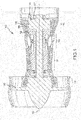
FIG. 1 illustrates a schematic cross-section view of a gas turbine engine in accordance with various embodiments; -
FIG. 2 illustrates a perspective view of a stator in accordance with various embodiments; -
FIG. 3 illustrates a perspective view of an anti-rotation lug in accordance with various embodiments; and -
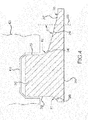
FIG. 4 illustrates a cross-section of an anti-rotation lug in accordance with various embodiments. - The detailed description of various embodiments herein makes reference to the accompanying drawings, which show various embodiments by way of illustration. While these various embodiments are described in sufficient detail to enable those skilled in the art to practice the disclosure, it should be understood that other embodiments may be realized and that logical, chemical, and mechanical changes may be made without departing from the scope of the disclosure. Thus, the detailed description herein is presented for exemplary purposes and not for limiting any embodiments disclosed herein. For example, the steps recited in any of the method or process descriptions may be executed in any order and are not necessarily limited to the order presented. Furthermore, any reference to singular includes plural embodiments, and any reference to more than one component or step may include a singular embodiment or step. Also, any reference to attached, fixed, connected, or the like may include permanent, removable, temporary, partial, full, and/or any other possible attachment options. Additionally, any reference to "without contact" (or similar phrases) may also include reduced contact or minimal contact.
- Referring to
FIG. 1 , a gas turbine engine 100 (such as a turbofan gas turbine engine) is illustrated, according to various embodiments.Gas turbine engine 100 is disposed aboutaxial centerline axis 120, which may also be referred to as axis ofrotation 120.Gas turbine engine 100 may comprise afan 140,compressor sections combustion section 180, and aturbine section 190. Air compressed in thecompressor sections combustion section 180 and expanded acrossturbine section 190.Turbine section 190 may includehigh pressure rotors 192 andlow pressure rotors 194, which rotate in response to the expansion.Compressor sections turbine section 190 may comprise alternating rows of rotary airfoils orblades 196 and static airfoils orvanes 198. A plurality ofbearings 115 may support spools in thegas turbine engine 100. -
FIG. 1 provides a general understanding of the sections in a gas turbine engine, and is not intended to limit the disclosure. The present disclosure may extend to all types of turbine engines, including turbofan gas turbine engines and turbojet engines, for all types of applications. - The forward-aft positions of
gas turbine engine 100 lie along axis ofrotation 120. For example,fan 140 may be referred to as forward ofturbine section 190 andturbine section 190 may be referred to as aft offan 140. Typically, during operation ofgas turbine engine 100, air flows from forward to aft, for example, fromfan 140 toturbine section 190. As air flows fromfan 140 to the more aft components ofgas turbine engine 100, axis ofrotation 120 may also generally define the direction of the air stream flow.
Referring toFIG. 2 , an aft view of a portion of astator 200 is illustrated, according to various embodiments. In various embodiments,stator 200 may comprise an exit guide vane for a high pressure compressor. However, in various embodiments,stator 200 may comprise any stator withingas turbine engine 100. In various embodiments,stator 200 may comprise a full ring stator. -
Stator 200 may comprise anouter shroud 210 and aninner shroud 220 radially spaced apart from each other. In various embodiments,outer shroud 210 may form a portion of an outer core engine structure, andinner shroud 220 may form a portion of an inner core engine structure to at least partially define an annular core gas flow path.Stator 200 may comprise a plurality ofvanes 230 disposed betweenouter shroud 210 andinner shroud 220. -
Stator 200 may increase pressure in the compressor, as well as direct air flow parallel toaxis 120. The air flow may exert a circumferential torque onvanes 230.Stator 200 may comprise anti-rotation lugs 240. Anti-rotation lugs 240 may be configured to counteract the circumferential torque in order to preventstator 200 from rotating as further discussed below. In various embodiments, anti-rotation lugs 240 may extend axially in an aft direction fromstator 200. In various embodiments, anti-rotation lugs 240 may extend frominner shroud 220. Anti-rotation lugs 240 may be configured to contact a stationary component, such as a diffuser case, in order to preventstator 200 from rotating. - In various embodiments,
outer shroud 210,inner shroud 220,vanes 230, andanti-rotation lugs 240 may comprise a single casting. In various embodiments,stator 200 may comprise an age-hardenable, nickel-based superalloy. - Referring to
FIGS. 3 and4 , enlarged and cross-sectional views ofanti-rotation lug 240 are illustrated in accordance with various embodiments of the present disclosure.Inner shroud 220 includes a stepped profile having aninner ring 232 and anouter ring 234.Inner ring 232 may extend axially fromouter ring 234. - As discussed above,
anti-rotation lug 240 may extend axially frominner ring 232. Anti-rotation lug may comprise abody 242 and atapered shoulder 244.Body 242 may comprise acontact face 243.Tapered shoulder 244 may be located betweencontact face 243 andinner ring 232.Body 242 and taperedshoulder 244 may intersect in a leadingfillet 246.Tapered shoulder 244 andinner ring 232 may intersect in ashoulder fillet 247. A trailingside 248 ofbody 242 andinner ring 232 may intersect in a trailingfillet 249. - In various embodiments,
contact face 243 may be configured to contact a stationary component, such as a diffuser case. The contact betweencontact face 243 and the stationary component may preventstator 200 from rotating. However, the contact may apply a significant load onanti-rotation lug 240.Tapered shoulder 244 distributes the stress concentration inanti-rotation lug 240. Thus, eachanti-rotation lug 240 in astator 200 is configured to accept higher loads without failing. It will be appreciated that if eachlug 240 can accept higher loads, then the total number of anti-rotation lugs 240 on a given stator may be decreased, thus decreasing weight of the stator and its manufacturing costs. For example,stator 200 may comprise twenty-fouranti-rotation lugs 240 with taperedshoulders 244, as opposed to a stator requiring thirty-six or more anti-rotation lugs without tapered shoulders. - It will be appreciated that the stepped profile described herein locally increases a load-carrying area of
inner shroud 220, thereby reducing nominal or net-section stress in the region ofinner ring 232, and decreasing the concentration of stress in the vicinity ofanti-rotation lug 240. It will also be appreciated that such stress reduction will allow for a greater amount of force to be applied to a particularanti-rotation lug 240 without causing failure thereof, and allow fewer anti-rotation lugs 240 to be utilized onstator 200. - Referring to
FIG. 4 , the radii of leadingfillet 246,shoulder fillet 247, trailingfillet 249, and the angle of taperedshoulder 244 may be iteratively calculated in order to distribute stress concentrations inanti-rotation lug 240. In various embodiments, trailingfillet 249 may comprise a radius R1 of about .125 inches (.318 cm) or about .100 inches - .150 inches (.254 cm - .762 cm). In various embodiments, leadingfillet 246 may comprise a radius R2 of about .062 inches (.157 cm) or about .05 inches - .08 inches (.127 cm - .203 cm). In various embodiments, an angle θ betweentapered shoulder 244 and axis ofrotation 120 may be about 70°, or about 60° - 80°. In various embodiments, a radius R3 ofshoulder fillet 247 may be about .250 inches (.635 cm), or between about .200 inches - .300 inches (.508 cm - .762 cm). - It has been found that increasing the radii of leading
fillet 246,shoulder fillet 247, and trailingfillet 249 generally better distributes stress concentrations inanti-rotation lug 240 caused by contact with a receivingslot 410 in adiffuser case 420. However, increasing the fillet radii in various embodiments also decreased the area ofcontact face 243. In various embodiments, the area ofcontact face 243 is maintained above minimum levels in order to meet bearing stress requirements. Bearing stress may be defined as the load oncontact face 243 divided by the area ofcontact face 243. Thus, in various embodiments, the fillet radii may be maximized while maintaining bearing stress levels below maximum levels. - Benefits and advantages have been described herein with regard to specific embodiments. Furthermore, the connecting lines shown in the various figures contained herein are intended to represent exemplary functional relationships and/or physical couplings between the various elements. It should be noted that many alternative or additional functional relationships or physical connections may be present in a practical system. However, the benefits, advantages, solutions to problems, and any elements that may cause any benefit, advantage, or solution to occur or become more pronounced are not to be construed as critical, required, or essential features or elements of the disclosure. The scope of the disclosure is accordingly to be limited by nothing other than the appended claims, in which reference to an element in the singular is not intended to mean "one and only one" unless explicitly so stated, but rather "one or more." Moreover, where a phrase similar to "at least one of A, B, or C" is used in the claims, it is intended that the phrase be interpreted to mean that A alone may be present in an embodiment, B alone may be present in an embodiment, C alone may be present in an embodiment, or that any combination of the elements A, B and C may be present in a single embodiment; for example, A and B, A and C, B and C, or A and B and C. Different cross-hatching is used throughout the figures to denote different parts but not necessarily to denote the same or different materials.
- Systems, methods and apparatus are provided herein. In the detailed description herein, references to "one embodiment", "an embodiment", "various embodiments", etc., indicate that the embodiment described may include a particular feature, structure, or characteristic, but every embodiment may not necessarily include the particular feature, structure, or characteristic. Moreover, such phrases are not necessarily referring to the same embodiment. Further, when a particular feature, structure, or characteristic is described in connection with an embodiment, it is submitted that it is within the knowledge of one skilled in the art to affect such feature, structure, or characteristic in connection with other embodiments whether or not explicitly described. After reading the description, it will be apparent to one skilled in the relevant art(s) how to implement the disclosure in alternative embodiments.
- Furthermore, no element, component, or method step in the present disclosure is intended to be dedicated to the public regardless of whether the element, component, or method step is explicitly recited in the claims. No claim element herein is to be construed under the provisions of 35 U.S.C. 112(f) unless the element is expressly recited using the phrase "means for." As used herein, the terms "comprises", "comprising", or any other variation thereof, are intended to cover a non-exclusive inclusion, such that a process, method, article, or apparatus that comprises a list of elements does not include only those elements but may include other elements not expressly listed or inherent to such process, method, article, or apparatus.
Claims (15)
- A stator (200) comprising:an outer shroud (210);at least one vane (230) coupled to the outer shroud (210);an inner shroud (220) coupled to the at least one vane (230); andan anti-rotation lug (240) coupled to the inner shroud (220), wherein the anti-rotation lug (240) comprises a body (242) and a tapered shoulder (244).
- The stator of claim 1, wherein the inner shroud (220) comprises an outer ring (234) and an inner ring (232).
- The stator of claim 2, wherein the anti-rotation lug (240) is coupled to the inner ring (232).
- The stator of claim 2 or 3, wherein the inner ring (232) extends axially from the outer ring (234) along an engine axis (120).
- The stator of any preceding claim, wherein the anti-rotation lug (240) comprises a leading fillet (246) located between the body (242) and the tapered shoulder (244).
- The stator of claim 5, wherein the leading fillet (246) comprises a radius of about .062 inches (1.57 mm).
- The stator of any preceding claim, further comprising a shoulder fillet (247) located between the tapered shoulder (244) and the inner shroud (220).
- The stator of any preceding claim, wherein the anti-rotation lug (240) is configured to contact a diffuser case (410) to prevent the stator (200) from rotating.
- The stator of any preceding claim, wherein the inner shroud (220) comprises a stepped profile.
- An assembly for a gas turbine engine (100), the assembly comprising:a stator (200) having an anti-rotation lug (240), wherein the anti-rotation lug (240) includes a tapered shoulder (244); anda diffuser case (420) configured to contact the anti-rotation lug (240).
- The assembly of claim 10, wherein the anti-rotation lug (240) is coupled to an inner ring (232) of the stator (200).
- The assembly of claim 10 or 11, wherein the stator (200) comprises an inner shroud (220), and wherein the inner shroud (220) comprises a stepped profile.
- The assembly of claim 10, 11 or 12, wherein the stator (200) comprises twenty-four anti-rotation lugs (240).
- The assembly of any of claims 10 to 13, wherein the stator (200) comprises a single component manufactured by at least one of casting, machining, additive manufacturing, and assembly of component parts.
- An anti-rotation lug (240), comprising:a body (242) comprising a contact face (243);a tapered shoulder (244); anda leading fillet (246) located between the contact face (243) and the tapered shoulder (244).
Applications Claiming Priority (1)
| Application Number | Priority Date | Filing Date | Title |
|---|---|---|---|
| US201461980169P | 2014-04-16 | 2014-04-16 |
Publications (2)
| Publication Number | Publication Date |
|---|---|
| EP2933437A1 true EP2933437A1 (en) | 2015-10-21 |
| EP2933437B1 EP2933437B1 (en) | 2019-07-24 |
Family
ID=53268602
Family Applications (1)
| Application Number | Title | Priority Date | Filing Date |
|---|---|---|---|
| EP15163772.5A Active EP2933437B1 (en) | 2014-04-16 | 2015-04-15 | Systems and methods for anti-rotation features |
Country Status (2)
| Country | Link |
|---|---|
| US (1) | US9745864B2 (en) |
| EP (1) | EP2933437B1 (en) |
Families Citing this family (2)
| Publication number | Priority date | Publication date | Assignee | Title |
|---|---|---|---|---|
| US10465559B2 (en) | 2017-12-13 | 2019-11-05 | United Technologies Corporation | Gas turbine engine vane attachment feature |
| FR3099792B1 (en) * | 2019-08-06 | 2021-07-30 | Safran Aircraft Engines | Aircraft turbine engine compressor comprising a device for locking a retaining ring |
Citations (3)
| Publication number | Priority date | Publication date | Assignee | Title |
|---|---|---|---|---|
| EP1308630A1 (en) * | 2001-10-31 | 2003-05-07 | Snecma Moteurs | Stator sector for a compressor of a turbomachine |
| DE102009003638A1 (en) * | 2008-03-31 | 2009-10-01 | General Electric Co. | System and method for mounting stator components |
| US20110243725A1 (en) * | 2010-03-31 | 2011-10-06 | General Electric Company | Turbine shroud mounting apparatus with anti-rotation feature |
Family Cites Families (10)
| Publication number | Priority date | Publication date | Assignee | Title |
|---|---|---|---|---|
| US2654566A (en) * | 1950-02-11 | 1953-10-06 | A V Roe Canada Ltd | Turbine nozzle guide vane construction |
| US3529904A (en) * | 1968-10-28 | 1970-09-22 | Westinghouse Electric Corp | Diaphragm seal structure |
| US4011718A (en) * | 1975-08-01 | 1977-03-15 | United Technologies Corporation | Gas turbine construction |
| US4621976A (en) * | 1985-04-23 | 1986-11-11 | United Technologies Corporation | Integrally cast vane and shroud stator with damper |
| US4856963A (en) * | 1988-03-23 | 1989-08-15 | United Technologies Corporation | Stator assembly for an axial flow rotary machine |
| US4820119A (en) * | 1988-05-23 | 1989-04-11 | United Technologies Corporation | Inner turbine seal |
| US6183192B1 (en) * | 1999-03-22 | 2001-02-06 | General Electric Company | Durable turbine nozzle |
| US6921246B2 (en) * | 2002-12-20 | 2005-07-26 | General Electric Company | Methods and apparatus for assembling gas turbine nozzles |
| US6932568B2 (en) * | 2003-02-27 | 2005-08-23 | General Electric Company | Turbine nozzle segment cantilevered mount |
| US8092163B2 (en) * | 2008-03-31 | 2012-01-10 | General Electric Company | Turbine stator mount |
-
2015
- 2015-03-23 US US14/665,780 patent/US9745864B2/en active Active
- 2015-04-15 EP EP15163772.5A patent/EP2933437B1/en active Active
Patent Citations (3)
| Publication number | Priority date | Publication date | Assignee | Title |
|---|---|---|---|---|
| EP1308630A1 (en) * | 2001-10-31 | 2003-05-07 | Snecma Moteurs | Stator sector for a compressor of a turbomachine |
| DE102009003638A1 (en) * | 2008-03-31 | 2009-10-01 | General Electric Co. | System and method for mounting stator components |
| US20110243725A1 (en) * | 2010-03-31 | 2011-10-06 | General Electric Company | Turbine shroud mounting apparatus with anti-rotation feature |
Also Published As
| Publication number | Publication date |
|---|---|
| EP2933437B1 (en) | 2019-07-24 |
| US20150300205A1 (en) | 2015-10-22 |
| US9745864B2 (en) | 2017-08-29 |
Similar Documents
| Publication | Publication Date | Title |
|---|---|---|
| US10533446B2 (en) | Alternative W-seal groove arrangement | |
| EP3045657B1 (en) | Sealing system between a bearing compartment and an interface between two shafts of a gas turbine engine | |
| US9394915B2 (en) | Seal land for static structure of a gas turbine engine | |
| US9784128B2 (en) | Systems and methods for engine bearings | |
| EP3121382A1 (en) | Gas turbine engines including channel-cooled hooks for retaining a part relative to an engine casing structure | |
| EP2615256B1 (en) | Spring "t" seal of a gas turbine | |
| EP3508700A2 (en) | Boas having radially extended protrusions | |
| EP2855898B1 (en) | Stator vane bumper ring | |
| EP3026217B1 (en) | Turbine rotor or stator segmented sideplates with anti-rotation | |
| EP2957721B1 (en) | Turbine section of a gas turbine engine, with disk cooling and an interstage seal having a particular geometry | |
| US20180128118A1 (en) | Turbine airfoil attachment with multi-radial serration profile | |
| EP2636852B1 (en) | Hybrid inner air seal for gas turbine engines | |
| EP3112615B1 (en) | Compressor section with a particular arrangement to hold a vane | |
| US10830048B2 (en) | Gas turbine rotor disk having scallop shield feature | |
| US9745864B2 (en) | Systems and methods for anti-rotational features | |
| US9976428B2 (en) | Turbine airfoil attachment with serration profile | |
| EP3553278B1 (en) | Axial stiffening ribs/augmentation fins | |
| US11111804B2 (en) | Inserts for slotted integrally bladed rotor | |
| US9045984B2 (en) | Stator vane mistake proofing | |
| US20200131916A1 (en) | Turbine blade assembly | |
| EP3098387B1 (en) | Installation fault tolerant damper | |
| US11408300B2 (en) | Rotor overspeed protection assembly |
Legal Events
| Date | Code | Title | Description |
|---|---|---|---|
| PUAI | Public reference made under article 153(3) epc to a published international application that has entered the european phase |
Free format text: ORIGINAL CODE: 0009012 |
|
| AK | Designated contracting states |
Kind code of ref document: A1 Designated state(s): AL AT BE BG CH CY CZ DE DK EE ES FI FR GB GR HR HU IE IS IT LI LT LU LV MC MK MT NL NO PL PT RO RS SE SI SK SM TR |
|
| AX | Request for extension of the european patent |
Extension state: BA ME |
|
| 17P | Request for examination filed |
Effective date: 20160420 |
|
| RBV | Designated contracting states (corrected) |
Designated state(s): AL AT BE BG CH CY CZ DE DK EE ES FI FR GB GR HR HU IE IS IT LI LT LU LV MC MK MT NL NO PL PT RO RS SE SI SK SM TR |
|
| RAP1 | Party data changed (applicant data changed or rights of an application transferred) |
Owner name: UNITED TECHNOLOGIES CORPORATION |
|
| RIC1 | Information provided on ipc code assigned before grant |
Ipc: F01D 25/24 20060101ALI20180917BHEP Ipc: F01D 9/04 20060101AFI20180917BHEP |
|
| GRAP | Despatch of communication of intention to grant a patent |
Free format text: ORIGINAL CODE: EPIDOSNIGR1 |
|
| STAA | Information on the status of an ep patent application or granted ep patent |
Free format text: STATUS: GRANT OF PATENT IS INTENDED |
|
| INTG | Intention to grant announced |
Effective date: 20190204 |
|
| GRAS | Grant fee paid |
Free format text: ORIGINAL CODE: EPIDOSNIGR3 |
|
| GRAA | (expected) grant |
Free format text: ORIGINAL CODE: 0009210 |
|
| STAA | Information on the status of an ep patent application or granted ep patent |
Free format text: STATUS: THE PATENT HAS BEEN GRANTED |
|
| AK | Designated contracting states |
Kind code of ref document: B1 Designated state(s): AL AT BE BG CH CY CZ DE DK EE ES FI FR GB GR HR HU IE IS IT LI LT LU LV MC MK MT NL NO PL PT RO RS SE SI SK SM TR |
|
| REG | Reference to a national code |
Ref country code: GB Ref legal event code: FG4D |
|
| REG | Reference to a national code |
Ref country code: CH Ref legal event code: EP |
|
| REG | Reference to a national code |
Ref country code: DE Ref legal event code: R096 Ref document number: 602015034145 Country of ref document: DE |
|
| REG | Reference to a national code |
Ref country code: AT Ref legal event code: REF Ref document number: 1158434 Country of ref document: AT Kind code of ref document: T Effective date: 20190815 |
|
| REG | Reference to a national code |
Ref country code: IE Ref legal event code: FG4D |
|
| REG | Reference to a national code |
Ref country code: NL Ref legal event code: MP Effective date: 20190724 |
|
| REG | Reference to a national code |
Ref country code: LT Ref legal event code: MG4D |
|
| REG | Reference to a national code |
Ref country code: AT Ref legal event code: MK05 Ref document number: 1158434 Country of ref document: AT Kind code of ref document: T Effective date: 20190724 |
|
| PG25 | Lapsed in a contracting state [announced via postgrant information from national office to epo] |
Ref country code: NO Free format text: LAPSE BECAUSE OF FAILURE TO SUBMIT A TRANSLATION OF THE DESCRIPTION OR TO PAY THE FEE WITHIN THE PRESCRIBED TIME-LIMIT Effective date: 20191024 Ref country code: FI Free format text: LAPSE BECAUSE OF FAILURE TO SUBMIT A TRANSLATION OF THE DESCRIPTION OR TO PAY THE FEE WITHIN THE PRESCRIBED TIME-LIMIT Effective date: 20190724 Ref country code: SE Free format text: LAPSE BECAUSE OF FAILURE TO SUBMIT A TRANSLATION OF THE DESCRIPTION OR TO PAY THE FEE WITHIN THE PRESCRIBED TIME-LIMIT Effective date: 20190724 Ref country code: LT Free format text: LAPSE BECAUSE OF FAILURE TO SUBMIT A TRANSLATION OF THE DESCRIPTION OR TO PAY THE FEE WITHIN THE PRESCRIBED TIME-LIMIT Effective date: 20190724 Ref country code: AT Free format text: LAPSE BECAUSE OF FAILURE TO SUBMIT A TRANSLATION OF THE DESCRIPTION OR TO PAY THE FEE WITHIN THE PRESCRIBED TIME-LIMIT Effective date: 20190724 Ref country code: HR Free format text: LAPSE BECAUSE OF FAILURE TO SUBMIT A TRANSLATION OF THE DESCRIPTION OR TO PAY THE FEE WITHIN THE PRESCRIBED TIME-LIMIT Effective date: 20190724 Ref country code: BG Free format text: LAPSE BECAUSE OF FAILURE TO SUBMIT A TRANSLATION OF THE DESCRIPTION OR TO PAY THE FEE WITHIN THE PRESCRIBED TIME-LIMIT Effective date: 20191024 Ref country code: NL Free format text: LAPSE BECAUSE OF FAILURE TO SUBMIT A TRANSLATION OF THE DESCRIPTION OR TO PAY THE FEE WITHIN THE PRESCRIBED TIME-LIMIT Effective date: 20190724 Ref country code: PT Free format text: LAPSE BECAUSE OF FAILURE TO SUBMIT A TRANSLATION OF THE DESCRIPTION OR TO PAY THE FEE WITHIN THE PRESCRIBED TIME-LIMIT Effective date: 20191125 |
|
| PG25 | Lapsed in a contracting state [announced via postgrant information from national office to epo] |
Ref country code: AL Free format text: LAPSE BECAUSE OF FAILURE TO SUBMIT A TRANSLATION OF THE DESCRIPTION OR TO PAY THE FEE WITHIN THE PRESCRIBED TIME-LIMIT Effective date: 20190724 Ref country code: ES Free format text: LAPSE BECAUSE OF FAILURE TO SUBMIT A TRANSLATION OF THE DESCRIPTION OR TO PAY THE FEE WITHIN THE PRESCRIBED TIME-LIMIT Effective date: 20190724 Ref country code: LV Free format text: LAPSE BECAUSE OF FAILURE TO SUBMIT A TRANSLATION OF THE DESCRIPTION OR TO PAY THE FEE WITHIN THE PRESCRIBED TIME-LIMIT Effective date: 20190724 Ref country code: IS Free format text: LAPSE BECAUSE OF FAILURE TO SUBMIT A TRANSLATION OF THE DESCRIPTION OR TO PAY THE FEE WITHIN THE PRESCRIBED TIME-LIMIT Effective date: 20191124 Ref country code: RS Free format text: LAPSE BECAUSE OF FAILURE TO SUBMIT A TRANSLATION OF THE DESCRIPTION OR TO PAY THE FEE WITHIN THE PRESCRIBED TIME-LIMIT Effective date: 20190724 Ref country code: GR Free format text: LAPSE BECAUSE OF FAILURE TO SUBMIT A TRANSLATION OF THE DESCRIPTION OR TO PAY THE FEE WITHIN THE PRESCRIBED TIME-LIMIT Effective date: 20191025 |
|
| PG25 | Lapsed in a contracting state [announced via postgrant information from national office to epo] |
Ref country code: TR Free format text: LAPSE BECAUSE OF FAILURE TO SUBMIT A TRANSLATION OF THE DESCRIPTION OR TO PAY THE FEE WITHIN THE PRESCRIBED TIME-LIMIT Effective date: 20190724 |
|
| PG25 | Lapsed in a contracting state [announced via postgrant information from national office to epo] |
Ref country code: IT Free format text: LAPSE BECAUSE OF FAILURE TO SUBMIT A TRANSLATION OF THE DESCRIPTION OR TO PAY THE FEE WITHIN THE PRESCRIBED TIME-LIMIT Effective date: 20190724 Ref country code: RO Free format text: LAPSE BECAUSE OF FAILURE TO SUBMIT A TRANSLATION OF THE DESCRIPTION OR TO PAY THE FEE WITHIN THE PRESCRIBED TIME-LIMIT Effective date: 20190724 Ref country code: PL Free format text: LAPSE BECAUSE OF FAILURE TO SUBMIT A TRANSLATION OF THE DESCRIPTION OR TO PAY THE FEE WITHIN THE PRESCRIBED TIME-LIMIT Effective date: 20190724 Ref country code: EE Free format text: LAPSE BECAUSE OF FAILURE TO SUBMIT A TRANSLATION OF THE DESCRIPTION OR TO PAY THE FEE WITHIN THE PRESCRIBED TIME-LIMIT Effective date: 20190724 Ref country code: DK Free format text: LAPSE BECAUSE OF FAILURE TO SUBMIT A TRANSLATION OF THE DESCRIPTION OR TO PAY THE FEE WITHIN THE PRESCRIBED TIME-LIMIT Effective date: 20190724 |
|
| PG25 | Lapsed in a contracting state [announced via postgrant information from national office to epo] |
Ref country code: CZ Free format text: LAPSE BECAUSE OF FAILURE TO SUBMIT A TRANSLATION OF THE DESCRIPTION OR TO PAY THE FEE WITHIN THE PRESCRIBED TIME-LIMIT Effective date: 20190724 Ref country code: SM Free format text: LAPSE BECAUSE OF FAILURE TO SUBMIT A TRANSLATION OF THE DESCRIPTION OR TO PAY THE FEE WITHIN THE PRESCRIBED TIME-LIMIT Effective date: 20190724 Ref country code: IS Free format text: LAPSE BECAUSE OF FAILURE TO SUBMIT A TRANSLATION OF THE DESCRIPTION OR TO PAY THE FEE WITHIN THE PRESCRIBED TIME-LIMIT Effective date: 20200224 Ref country code: SK Free format text: LAPSE BECAUSE OF FAILURE TO SUBMIT A TRANSLATION OF THE DESCRIPTION OR TO PAY THE FEE WITHIN THE PRESCRIBED TIME-LIMIT Effective date: 20190724 |
|
| REG | Reference to a national code |
Ref country code: DE Ref legal event code: R097 Ref document number: 602015034145 Country of ref document: DE |
|
| PLBE | No opposition filed within time limit |
Free format text: ORIGINAL CODE: 0009261 |
|
| STAA | Information on the status of an ep patent application or granted ep patent |
Free format text: STATUS: NO OPPOSITION FILED WITHIN TIME LIMIT |
|
| PG2D | Information on lapse in contracting state deleted |
Ref country code: IS |
|
| 26N | No opposition filed |
Effective date: 20200603 |
|
| PG25 | Lapsed in a contracting state [announced via postgrant information from national office to epo] |
Ref country code: SI Free format text: LAPSE BECAUSE OF FAILURE TO SUBMIT A TRANSLATION OF THE DESCRIPTION OR TO PAY THE FEE WITHIN THE PRESCRIBED TIME-LIMIT Effective date: 20190724 |
|
| PG25 | Lapsed in a contracting state [announced via postgrant information from national office to epo] |
Ref country code: MC Free format text: LAPSE BECAUSE OF FAILURE TO SUBMIT A TRANSLATION OF THE DESCRIPTION OR TO PAY THE FEE WITHIN THE PRESCRIBED TIME-LIMIT Effective date: 20190724 |
|
| REG | Reference to a national code |
Ref country code: CH Ref legal event code: PL |
|
| PG25 | Lapsed in a contracting state [announced via postgrant information from national office to epo] |
Ref country code: LI Free format text: LAPSE BECAUSE OF NON-PAYMENT OF DUE FEES Effective date: 20200430 Ref country code: CH Free format text: LAPSE BECAUSE OF NON-PAYMENT OF DUE FEES Effective date: 20200430 Ref country code: LU Free format text: LAPSE BECAUSE OF NON-PAYMENT OF DUE FEES Effective date: 20200415 |
|
| REG | Reference to a national code |
Ref country code: BE Ref legal event code: MM Effective date: 20200430 |
|
| PG25 | Lapsed in a contracting state [announced via postgrant information from national office to epo] |
Ref country code: BE Free format text: LAPSE BECAUSE OF NON-PAYMENT OF DUE FEES Effective date: 20200430 |
|
| PG25 | Lapsed in a contracting state [announced via postgrant information from national office to epo] |
Ref country code: IE Free format text: LAPSE BECAUSE OF NON-PAYMENT OF DUE FEES Effective date: 20200415 |
|
| PG25 | Lapsed in a contracting state [announced via postgrant information from national office to epo] |
Ref country code: MT Free format text: LAPSE BECAUSE OF FAILURE TO SUBMIT A TRANSLATION OF THE DESCRIPTION OR TO PAY THE FEE WITHIN THE PRESCRIBED TIME-LIMIT Effective date: 20190724 Ref country code: CY Free format text: LAPSE BECAUSE OF FAILURE TO SUBMIT A TRANSLATION OF THE DESCRIPTION OR TO PAY THE FEE WITHIN THE PRESCRIBED TIME-LIMIT Effective date: 20190724 |
|
| PG25 | Lapsed in a contracting state [announced via postgrant information from national office to epo] |
Ref country code: MK Free format text: LAPSE BECAUSE OF FAILURE TO SUBMIT A TRANSLATION OF THE DESCRIPTION OR TO PAY THE FEE WITHIN THE PRESCRIBED TIME-LIMIT Effective date: 20190724 |
|
| REG | Reference to a national code |
Ref country code: DE Ref legal event code: R081 Ref document number: 602015034145 Country of ref document: DE Owner name: RAYTHEON TECHNOLOGIES CORPORATION (N.D.GES.D.S, US Free format text: FORMER OWNER: UNITED TECHNOLOGIES CORP., FARMINGTON, CONN., US Ref country code: DE Ref legal event code: R081 Ref document number: 602015034145 Country of ref document: DE Owner name: RTX CORPORATION (N.D.GES.D. STAATES DELAWARE),, US Free format text: FORMER OWNER: UNITED TECHNOLOGIES CORP., FARMINGTON, CONN., US |
|
| P01 | Opt-out of the competence of the unified patent court (upc) registered |
Effective date: 20230520 |
|
| PGFP | Annual fee paid to national office [announced via postgrant information from national office to epo] |
Ref country code: DE Payment date: 20250319 Year of fee payment: 11 |
|
| REG | Reference to a national code |
Ref country code: DE Ref legal event code: R081 Ref document number: 602015034145 Country of ref document: DE Owner name: RTX CORPORATION (N.D.GES.D. STAATES DELAWARE),, US Free format text: FORMER OWNER: RAYTHEON TECHNOLOGIES CORPORATION (N.D.GES.D.STAATES DELAWARE), ARLINGTON, VA, US |
|
| PGFP | Annual fee paid to national office [announced via postgrant information from national office to epo] |
Ref country code: GB Payment date: 20260319 Year of fee payment: 12 |
|
| PGFP | Annual fee paid to national office [announced via postgrant information from national office to epo] |
Ref country code: FR Payment date: 20260320 Year of fee payment: 12 |