EP2933238B1 - Manufacturing method for an optical fibre preform with a non circular core and a doped cladding having a predetermined numerical aperture - Google Patents
Manufacturing method for an optical fibre preform with a non circular core and a doped cladding having a predetermined numerical aperture Download PDFInfo
- Publication number
- EP2933238B1 EP2933238B1 EP15163788.1A EP15163788A EP2933238B1 EP 2933238 B1 EP2933238 B1 EP 2933238B1 EP 15163788 A EP15163788 A EP 15163788A EP 2933238 B1 EP2933238 B1 EP 2933238B1
- Authority
- EP
- European Patent Office
- Prior art keywords
- core
- dopant concentration
- parameter
- blank
- section
- Prior art date
- Legal status (The legal status is an assumption and is not a legal conclusion. Google has not performed a legal analysis and makes no representation as to the accuracy of the status listed.)
- Active
Links
- 238000005253 cladding Methods 0.000 title claims description 79
- 238000004519 manufacturing process Methods 0.000 title claims description 25
- 239000013307 optical fiber Substances 0.000 title description 6
- 239000002019 doping agent Substances 0.000 claims description 50
- 239000000835 fiber Substances 0.000 claims description 42
- 238000000034 method Methods 0.000 claims description 36
- 239000011248 coating agent Substances 0.000 claims description 19
- 238000000576 coating method Methods 0.000 claims description 19
- 230000004888 barrier function Effects 0.000 claims description 13
- 239000000463 material Substances 0.000 claims description 7
- 238000012545 processing Methods 0.000 claims description 3
- 229910052757 nitrogen Inorganic materials 0.000 claims description 2
- 239000004020 conductor Substances 0.000 claims 7
- 230000000903 blocking effect Effects 0.000 claims 3
- -1 fluor compound Chemical class 0.000 claims 1
- 239000011162 core material Substances 0.000 description 80
- 229910052731 fluorine Inorganic materials 0.000 description 36
- 239000011737 fluorine Substances 0.000 description 36
- YCKRFDGAMUMZLT-UHFFFAOYSA-N Fluorine atom Chemical compound [F] YCKRFDGAMUMZLT-UHFFFAOYSA-N 0.000 description 34
- 230000003287 optical effect Effects 0.000 description 32
- 230000000694 effects Effects 0.000 description 8
- 239000000758 substrate Substances 0.000 description 8
- 238000000151 deposition Methods 0.000 description 7
- 230000008021 deposition Effects 0.000 description 5
- 238000013461 design Methods 0.000 description 5
- 230000005540 biological transmission Effects 0.000 description 4
- 239000007795 chemical reaction product Substances 0.000 description 4
- 238000005259 measurement Methods 0.000 description 4
- 239000000203 mixture Substances 0.000 description 4
- 230000005855 radiation Effects 0.000 description 4
- 239000012467 final product Substances 0.000 description 3
- VYPSYNLAJGMNEJ-UHFFFAOYSA-N Silicium dioxide Chemical compound O=[Si]=O VYPSYNLAJGMNEJ-UHFFFAOYSA-N 0.000 description 2
- 230000009471 action Effects 0.000 description 2
- 230000008878 coupling Effects 0.000 description 2
- 238000010168 coupling process Methods 0.000 description 2
- 238000005859 coupling reaction Methods 0.000 description 2
- 238000013016 damping Methods 0.000 description 2
- 150000002221 fluorine Chemical class 0.000 description 2
- 150000002222 fluorine compounds Chemical class 0.000 description 2
- 230000008569 process Effects 0.000 description 2
- 239000000047 product Substances 0.000 description 2
- 230000003595 spectral effect Effects 0.000 description 2
- 238000007740 vapor deposition Methods 0.000 description 2
- ZOXJGFHDIHLPTG-UHFFFAOYSA-N Boron Chemical compound [B] ZOXJGFHDIHLPTG-UHFFFAOYSA-N 0.000 description 1
- OAICVXFJPJFONN-UHFFFAOYSA-N Phosphorus Chemical compound [P] OAICVXFJPJFONN-UHFFFAOYSA-N 0.000 description 1
- 229910052782 aluminium Inorganic materials 0.000 description 1
- XAGFODPZIPBFFR-UHFFFAOYSA-N aluminium Chemical compound [Al] XAGFODPZIPBFFR-UHFFFAOYSA-N 0.000 description 1
- 229910052796 boron Inorganic materials 0.000 description 1
- 238000005352 clarification Methods 0.000 description 1
- 239000011258 core-shell material Substances 0.000 description 1
- 238000012937 correction Methods 0.000 description 1
- 230000007547 defect Effects 0.000 description 1
- 230000001419 dependent effect Effects 0.000 description 1
- 238000011161 development Methods 0.000 description 1
- 230000005670 electromagnetic radiation Effects 0.000 description 1
- 238000011156 evaluation Methods 0.000 description 1
- 238000012681 fiber drawing Methods 0.000 description 1
- 229910052732 germanium Inorganic materials 0.000 description 1
- GNPVGFCGXDBREM-UHFFFAOYSA-N germanium atom Chemical compound [Ge] GNPVGFCGXDBREM-UHFFFAOYSA-N 0.000 description 1
- 239000011521 glass Substances 0.000 description 1
- 238000000227 grinding Methods 0.000 description 1
- 230000006872 improvement Effects 0.000 description 1
- 229910052747 lanthanoid Inorganic materials 0.000 description 1
- 150000002602 lanthanoids Chemical class 0.000 description 1
- 238000002156 mixing Methods 0.000 description 1
- 238000005457 optimization Methods 0.000 description 1
- 238000013386 optimize process Methods 0.000 description 1
- 238000012856 packing Methods 0.000 description 1
- 229910052698 phosphorus Inorganic materials 0.000 description 1
- 239000011574 phosphorus Substances 0.000 description 1
- 230000010287 polarization Effects 0.000 description 1
- 238000005498 polishing Methods 0.000 description 1
- 238000004321 preservation Methods 0.000 description 1
- 238000004886 process control Methods 0.000 description 1
- 230000009467 reduction Effects 0.000 description 1
- 239000011265 semifinished product Substances 0.000 description 1
- 238000001228 spectrum Methods 0.000 description 1
- 230000007847 structural defect Effects 0.000 description 1
- 238000002207 thermal evaporation Methods 0.000 description 1
Images
Classifications
-
- C—CHEMISTRY; METALLURGY
- C03—GLASS; MINERAL OR SLAG WOOL
- C03B—MANUFACTURE, SHAPING, OR SUPPLEMENTARY PROCESSES
- C03B37/00—Manufacture or treatment of flakes, fibres, or filaments from softened glass, minerals, or slags
- C03B37/01—Manufacture of glass fibres or filaments
- C03B37/012—Manufacture of preforms for drawing fibres or filaments
- C03B37/01205—Manufacture of preforms for drawing fibres or filaments starting from tubes, rods, fibres or filaments
- C03B37/01211—Manufacture of preforms for drawing fibres or filaments starting from tubes, rods, fibres or filaments by inserting one or more rods or tubes into a tube
-
- G—PHYSICS
- G02—OPTICS
- G02B—OPTICAL ELEMENTS, SYSTEMS OR APPARATUS
- G02B6/00—Light guides; Structural details of arrangements comprising light guides and other optical elements, e.g. couplings
- G02B6/02—Optical fibres with cladding with or without a coating
-
- C—CHEMISTRY; METALLURGY
- C03—GLASS; MINERAL OR SLAG WOOL
- C03B—MANUFACTURE, SHAPING, OR SUPPLEMENTARY PROCESSES
- C03B2201/00—Type of glass produced
- C03B2201/06—Doped silica-based glasses
- C03B2201/08—Doped silica-based glasses doped with boron or fluorine or other refractive index decreasing dopant
- C03B2201/10—Doped silica-based glasses doped with boron or fluorine or other refractive index decreasing dopant doped with boron
-
- C—CHEMISTRY; METALLURGY
- C03—GLASS; MINERAL OR SLAG WOOL
- C03B—MANUFACTURE, SHAPING, OR SUPPLEMENTARY PROCESSES
- C03B2201/00—Type of glass produced
- C03B2201/06—Doped silica-based glasses
- C03B2201/08—Doped silica-based glasses doped with boron or fluorine or other refractive index decreasing dopant
- C03B2201/12—Doped silica-based glasses doped with boron or fluorine or other refractive index decreasing dopant doped with fluorine
-
- C—CHEMISTRY; METALLURGY
- C03—GLASS; MINERAL OR SLAG WOOL
- C03B—MANUFACTURE, SHAPING, OR SUPPLEMENTARY PROCESSES
- C03B2201/00—Type of glass produced
- C03B2201/06—Doped silica-based glasses
- C03B2201/20—Doped silica-based glasses doped with non-metals other than boron or fluorine
- C03B2201/28—Doped silica-based glasses doped with non-metals other than boron or fluorine doped with phosphorus
-
- C—CHEMISTRY; METALLURGY
- C03—GLASS; MINERAL OR SLAG WOOL
- C03B—MANUFACTURE, SHAPING, OR SUPPLEMENTARY PROCESSES
- C03B2201/00—Type of glass produced
- C03B2201/06—Doped silica-based glasses
- C03B2201/30—Doped silica-based glasses doped with metals, e.g. Ga, Sn, Sb, Pb or Bi
- C03B2201/31—Doped silica-based glasses doped with metals, e.g. Ga, Sn, Sb, Pb or Bi doped with germanium
-
- C—CHEMISTRY; METALLURGY
- C03—GLASS; MINERAL OR SLAG WOOL
- C03B—MANUFACTURE, SHAPING, OR SUPPLEMENTARY PROCESSES
- C03B2201/00—Type of glass produced
- C03B2201/06—Doped silica-based glasses
- C03B2201/30—Doped silica-based glasses doped with metals, e.g. Ga, Sn, Sb, Pb or Bi
- C03B2201/32—Doped silica-based glasses doped with metals, e.g. Ga, Sn, Sb, Pb or Bi doped with aluminium
-
- C—CHEMISTRY; METALLURGY
- C03—GLASS; MINERAL OR SLAG WOOL
- C03B—MANUFACTURE, SHAPING, OR SUPPLEMENTARY PROCESSES
- C03B2201/00—Type of glass produced
- C03B2201/06—Doped silica-based glasses
- C03B2201/30—Doped silica-based glasses doped with metals, e.g. Ga, Sn, Sb, Pb or Bi
- C03B2201/34—Doped silica-based glasses doped with metals, e.g. Ga, Sn, Sb, Pb or Bi doped with rare earth metals, i.e. with Sc, Y or lanthanides, e.g. for laser-amplifiers
-
- C—CHEMISTRY; METALLURGY
- C03—GLASS; MINERAL OR SLAG WOOL
- C03B—MANUFACTURE, SHAPING, OR SUPPLEMENTARY PROCESSES
- C03B2203/00—Fibre product details, e.g. structure, shape
- C03B2203/10—Internal structure or shape details
- C03B2203/12—Non-circular or non-elliptical cross-section, e.g. planar core
-
- H—ELECTRICITY
- H01—ELECTRIC ELEMENTS
- H01S—DEVICES USING THE PROCESS OF LIGHT AMPLIFICATION BY STIMULATED EMISSION OF RADIATION [LASER] TO AMPLIFY OR GENERATE LIGHT; DEVICES USING STIMULATED EMISSION OF ELECTROMAGNETIC RADIATION IN WAVE RANGES OTHER THAN OPTICAL
- H01S3/00—Lasers, i.e. devices using stimulated emission of electromagnetic radiation in the infrared, visible or ultraviolet wave range
- H01S3/05—Construction or shape of optical resonators; Accommodation of active medium therein; Shape of active medium
- H01S3/06—Construction or shape of active medium
- H01S3/063—Waveguide lasers, i.e. whereby the dimensions of the waveguide are of the order of the light wavelength
- H01S3/067—Fibre lasers
- H01S3/06708—Constructional details of the fibre, e.g. compositions, cross-section, shape or tapering
- H01S3/06712—Polarising fibre; Polariser
Definitions
- the height of the NA of an optical waveguide can in principle be adjusted by the refractive index difference between the core region and the cladding region. For round nuclei, it is possible to calculate the NA of the optical waveguide from this refractive index difference. If, for example, an undoped core material is used and the cladding region is to be doped with fluorine, the required concentration of fluorine in the cladding region can be calculated from the required refractive index difference and adjusted during production of the preform.
- the DE 10 2009 004 756 A1 describes a method in which a rectangular core rod is enclosed with a jacket tube. As a result, the thermal load is reduced and improved angularity is obtained.
- a most homogeneous dopant concentration in the cladding region is achieved by depositing a first cladding layer for filling the valley regions between the corners under first deposition conditions. Thereafter, the preform is ground round and prepared for the deposition of the second cladding layer. This is then applied under deposition conditions which may be identical to the first, but not have to. It is designed so that the dopant concentration in the second cladding layer is identical to the first cladding layer.
- a nominal dopant concentration is set for the production of the jacket region.
- the nominal dopant concentration is determined from the effective dopant concentration as a function of parameters that describe the fiber structure of the optical waveguide. These parameters are the intended core geometry of the optical waveguide and / or mechanical parameters of the fiber structure of the optical waveguide to be manufactured.
- the preform core is produced with the intended geometry of the cross section of the preform. Subsequently, the preforming core is surrounded by a cladding region with the nominal dopant concentration.
- the effective dopant concentration c eff and the nominal dopant concentration c nom and the scaling factor F are linked according to the invention via the following relationship: c eff ⁇ F ⁇ c nom .
- the scaling factor F with a parameter set V, C, S and N on the relationship F V ⁇ 1 + C - 1 ⁇ N ⁇ 1 + S - 1 ⁇ N calculated.
- V is a measure of a corner fillet
- C describes an influence of a coating of the optical waveguide
- N is a corner number of the core
- S describes an influence of a barrier layer.
- the nominal dopant concentration is increased compared to the effective dopant concentration, and an evaluation of a parameter describing a corner rounding V of the non-round cross-section is performed to determine the degree of increase of the effective dopant concentration to the nominal dopant concentration.
- the nominal dopant concentration is increased compared to the effective dopant concentration, with the Increase of the dopant concentration in addition to the parameter of the corner fillet V is determined from a number of corners N and from the parameters C and S, which describe an influence of a proposed coating (parameter C) and a barrier layer (parameter S).
- the nominal dopant concentration is increased compared to the effective dopant concentration, with the Increase of the dopant concentration in addition to the parameter of the corner fillet V is determined from a number of corners N and from the parameters C and S, which describe an influence of a proposed coating (parameter C) and a barrier layer (parameter S).
- the parameter S of the influence of the barrier layer is determined in an expedient embodiment of the method of the thermal expansion coefficient CTE S of the material of the barrier layer and the thermal expansion coefficient CTE C of the cladding of the optical waveguide to be produced.
- the parameter V of the corner fillet results in one embodiment of the method of three descriptive characteristics, namely an outside diameter Ad describing the non-round cross section, an inside diameter Id inscribed in the non-round cross section and a corner number N of the non-round core.
- a cladding region with a cladding cross-section adapted to the cross-sectional geometry of the preform core is applied such that the core-cladding ratio is constant over the entire cross-section of the preform.
- the constant core-to-shell ratio throughout the entire cross-section of the preform implies that also the cladding region of the preform has a cross-section at least similar to that of the core of the preform. This means, in particular, that the cross section of the cladding region is also non-round.
- the preform core is manufactured in the required cross-sectional geometry, wherein subsequently a Aufkollabieren a jacket tube with the nominal dopant concentration. This makes it possible in particular the mentioned constant Realizing the core-sheath ratio particularly easy over the preform cross-section.
- Fluorine or a fluorine compound is provided in particular as dopant. This lowers the refractive index of the cladding region.
- the cladding layer of the preform has a nominal dopant concentration which is increased compared to an effective dopant concentration of a preform for a round core geometry optical fiber having an identical numerical aperture.
- the nominal dopant concentration is in particular greater than or equal to the effective dopant concentration multiplied by a geometric correction factor describing at least the cross-sectional shape of the core.
- the ratio of the core diameter to the diameter of the stress-generating jacket region is greater than 2.5, preferably greater than 4 and particularly preferably greater than 5.8.
- a square core rod is surrounded by a fluorine-doped cladding layer.
- the fluorine concentration is adjusted in such a way that a numerical aperture of 0.20 is to be expected on a round core geometry.
- the fiber draw at the initial stage is selected to be at a high draw temperature such that an almost circular fiber is drawn from the quadratic preform due to the surface tension.
- An NA measurement on this fiber confirmed the target value of 0.20.
- an NA of 0.16 was achieved.
- the nominal dopant concentration of the cladding region is represented by a nominal fluorine concentration.
- the following explanations are then transferable to other dopants in the context of expert action.
- a fluorine concentration is thus determined which compensates for the NA-lowering effects of the optical waveguide geometry and thus results in the desired NA at the final optical waveguide.
- the parameters used are mainly the number of corners, the corner rounding and stresses generated by further cladding layers.
- a numerical aperture for the optical waveguide is given, this is converted accordingly into the effective fluorine concentration and from this the nominal fluorine concentration can then be determined depending on the design of the optical waveguide.
- This nominal fluorine concentration is used as a default during manufacturing.
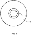
- Fig. 2 shows, for example, a design with a core 1, a jacket 2 and a barrier layer 3.
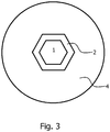
- Fig. 3 shows a structure with a core 1, a jacket 2 and a surrounding coating 4.
- the jacket is referred to in the following versions as cladding. In the following explanations, reference is made to the respective figures.
- F V ⁇ 1 + C - 1 ⁇ N ⁇ 1 + S - 1 ⁇ N
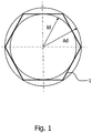
- Ad describes the outer diameter of the circle described in the N-corner.
- Id describes the inner diameter of the circle inscribed in the N-corner.
- the parameter of the corner fillet V is a measure of how much the achieved shape of the non-round fiber core deviates from the ideal shape of a polygon and merges into that of a circle.
- the corner fillet is identical to zero, and increasing values for V indicate that the ideal polygon shape is increasingly merging into that of a circle, with the sides of the polygon in particular becoming increasingly arcuate.
- the jacket layer thickness can be optimized by a non-circular shell geometry. If a round sheath layer becomes a 6-cornered core geometry, the so-called clad to core diameter ratio inevitably changes.
- the shell geometry is adapted to the core geometry.
- An example is in this Fig. 3 shown. Shown here is a structure of a core 1, a cladding 2 and a surrounding coating 4. If a 6-sided jacket 2 is applied to the 6-cornered core, the CCDR is the same size at all points and the material cost considerably less.
- a non-circular shell geometry can also prove to be advantageous if the fibers are to be further processed into fiber bundles later, because thus the gaps between individual fibers in the bundle production can be significantly reduced. This results in better processability during bundle production. Since hardly any hollow spaces available In addition, the fiber geometry is much better preserved when many single fibers merge into a bundle.
- fiber bundles and fibers which are particularly stable against electromagnetic radiation by a suitable choice of the core and sheath materials and optimized process conditions.
- a resistance to ultraviolet or higher energy radiation such as X-rays or gamma radiation is set.
- a square core rod was surrounded with a fluorine-doped cladding layer.
- the fluorine concentration was adjusted in such a way that a numerical aperture of 0.20 was achieved on a round core geometry.
- this preform was warped into a fiber, the fiber draw was so high in the initial range that a nearly circular fiber was drawn due to the surface tension of the square preform.
- An NA measurement on this fiber confirmed the target value of 0.20.
- warping the preform with reduced draw temperature and maintaining the non-round core geometry an NA of 0.16 was achieved. It follows that the corner rounding of the preform during fiber drawing need not necessarily be preserved. Due to high drawing temperatures, the corner rounding can be increased.
- An essential parameter for achieving this transmission improvement is the reduction of the pulling speed.
- the slower the fiber is pulled the slower the fiber cools and thus increases the duration at which structural defects in the glass structure can heal. Due to the slow pulling speed, the duration of stay in hot Ziehofen is increased, so that even here can already take place defects.
- the fibers with non-round cores can be used as single fibers, but also a use in fiber bundles is possible.
- the jacket is formed in a polygonal shape.
- the packing density of fiber bundles with non-circular outer geometries is higher compared to round fibers. As a result, the light-conducting surface is also increased and the bundle has a smaller proportion of non-light-conducting regions.
- a rectangular core is used.
- the aspect ratios can be chosen freely. However, there are certain limits that depend on the manufacturing process used. If the cladding layer is applied using a jacketing method, the geometry of the jacketing tube is determined as a function of the aspect ratio. The larger the aspect ratio is, the more oval the pipe is made to have the most even gap between the pipe and the pipe To comply with the preform.
- the inner geometry of the tube is adapted to the outer geometry of the substrate. In this case, for example, tubes are produced with polygonal internal geometries and these alskollabiert on corresponding substrates. The gap dimensions between the substrate and the tube are almost identical over the entire substrate circumference, so that no material shifts or bubbles occur in the interface during jacketing.
- the cladding is produced with two different refractive indices, so that an inner and an outer cladding arises.
- the inner cladding has a higher refractive index than the outer cladding, both refractive indices being smaller than the core refractive index.
- the numerical aperture can be selectively influenced and adjusted.
- the layer thickness of the inner cladding can also be used to enhance or weaken the effect of the inner cladding.
- a mother substrate can be made with an internal cladding and then provided with a second outer cladding depending on the desired numerical aperture on the final product, so that the desired parameters are obtained on the final product.
- a mother substrate that can be used for different target values, the manufacturing effort and time is significantly reduced. It can also be used for the production of the mother substrate on very large substrates, which minimizes the processing costs, for example, caused by grinding or polishing the surface, in relation to the mass of the final product.
- the increased freedom of design of the preform made possible by the second cladding does not require the complete master rod for one specific product design are used. Rather, first a larger series can be made, are separated from the smaller, specially designed subsets for different end products and separately processed separately.
- the concepts mentioned in the exemplary embodiments are not restricted to special outer diameters of the semifinished product or end product.
- the preforms may have diameters greater than 15 mm, preferably a range of 20 to 50 mm, and more preferably a range of between 25 and 35 mm. In this diameter range, the necessary processing steps can be performed at lower temperatures compared to much thicker preforms. This has proven to be advantageous for maintaining the angularity of the core area.
- the fibers from the preforms described here generally have outer diameters of up to 1200 .mu.m, a diameter range of from 75 to 600 .mu.m being preferred and a range of between 200 and 500 .mu.m being particularly preferred.
- preforms can also be drawn or stretched to larger diameters, so that the end product is not a fiber but a light-conducting rod. Diameters of 1.2 to 15 mm are possible, the range between 2 and 6 mm being preferred, and the range between 2.5 and 3.5 mm being particularly preferred.
Landscapes
- Physics & Mathematics (AREA)
- Engineering & Computer Science (AREA)
- Chemical & Material Sciences (AREA)
- General Physics & Mathematics (AREA)
- Optics & Photonics (AREA)
- Life Sciences & Earth Sciences (AREA)
- General Life Sciences & Earth Sciences (AREA)
- Geochemistry & Mineralogy (AREA)
- Manufacturing & Machinery (AREA)
- Materials Engineering (AREA)
- Organic Chemistry (AREA)
- Manufacture, Treatment Of Glass Fibers (AREA)
Description
Unter einem Lichtwellenleiter werden nachfolgend gleichermaßen Lichtleitfasern und und Lichtleitstäbe verstanden. Nichtrunde Kerne werden in derartigen Lichtwellenleitern verwendet, um zum Beispiel die Modenmischung zu verbessern. Das kann dazu genutzt werden, um Strahlprofile zu homogenisieren oder auch die Einkoppeleffizienz von Pumplicht in aktiven Laserfasern zu erhöhen. Die Verwendung von nicht-runden Kernformen bringt allerdings auch einige Nachteile mit sich. Die Nachteile resultieren vorwiegend aus der Modenmischung. Diese führt dazu, dass bestimmte Modengruppen, die vorwiegend in den Randbereichen des Faserkerns propagieren, eine erhöhte Dämpfung aufweisen. Dieser Effekt tritt dann besonders stark auf, wenn die Eckenverrundung des Kernstabes minimal ist. Außerdem geht neben der erhöhten Dämpfung auch ein Absinken der numerischen Apertur einher. Nachfolgend wird der Begriff "numerische Apertur" durch NA abgekürzt.Under an optical waveguide are understood in the following equally optical fibers and and Lichtleitstäbe. Non-round cores are used in such optical waveguides to improve, for example, mode mixing. This can be used to homogenize beam profiles or to increase the coupling efficiency of pump light in active laser fibers. However, the use of non-round core shapes also has some disadvantages. The disadvantages result mainly from the mode mixture. This leads to certain mode groups, which propagate predominantly in the edge regions of the fiber core, having increased damping. This effect is particularly pronounced when the corner rounding of the core bar is minimal. In addition, in addition to the increased attenuation and a decrease in the numerical aperture is accompanied. Hereinafter, the term "numerical aperture" is abbreviated to NA.
In vielen Anwendungen ist es sehr wichtig, eine bestimmte NA zu erreichen. Die Höhe der NA eines Lichtwellenleiters kann prinzipiell durch den Brechzahlunterschied zwischen dem Kernbereich und dem Mantelbereich eingestellt werden. Für runde Kerne ist es möglich, aus diesem Brechzahlunterschied die NA des Lichtwellenleiters zu berechnen. Wenn beispielsweise ein undotiertes Kernmaterial verwendet wird und der Mantelbereich mit Fluor dotiert werden soll, kann aus der benötigten Brechzahldifferenz die notwendige Konzentration an Fluor im Mantelbereich berechnet und bei der Herstellung der Vorform eingestellt werden.In many applications it is very important to reach a specific NA. The height of the NA of an optical waveguide can in principle be adjusted by the refractive index difference between the core region and the cladding region. For round nuclei, it is possible to calculate the NA of the optical waveguide from this refractive index difference. If, for example, an undoped core material is used and the cladding region is to be doped with fluorine, the required concentration of fluorine in the cladding region can be calculated from the required refractive index difference and adjusted during production of the preform.
Dieses einfache Vorgehen führt jedoch bei nicht-runden Kerngeometrien auf Grund der eingangs beschriebenen zusätzlichen Verluste durch die Modenmischung nicht zum Erfolg.However, this simple procedure does not lead to success in non-round core geometries due to the additional losses described above by the mode mixture.
Aus dem Stand der Technik sind verschiedene Verfahren für die Herstellung von nicht-runden Kernen bekannt.Various methods for the production of non-round cores are known from the prior art.
In der
Die
Die
In der
Die
In der
Somit besteht die Aufgabe darin, eine Vorform für Lichtwellenleiter mit nicht-runden Kernen so herzustellen, dass damit eine vorgegebene NA des aus dieser Vorform gefertigten Lichtwellenleiters sicher erreicht werden kann und ein entsprechendes Fertigungsverfahren anzugeben. Weiterhin wird eine Vorform für einen Lichtwellenleiter beschrieben, mit dem es gelingt, im fertigen Lichtwellenleiter eine geforderte NA genau einzustellen.
Die Aufgabe wird mit einem Verfahren zur Fertigung einer Vorform zur Herstellung eines Lichtwellenleiters mit den Merkmalen des Anspruchs 1 gelöst. Die jeweiligen Unteransprüche enthalten zweckmäßige bzw. vorteilhafte Ausgestaltungen des Verfahrens Bei dem Verfahren zur Fertigung einer Vorform zur Herstellung eines Lichtwellenleiters, enthaltend einen Mantelbereich und einen Vorformkern mit einem nicht-runden, insbesondere polygonalen Querschnitt ist ein Wert für die numerische Apertur (NA) vorgegeben, den der zu fertigende Lichtwellenleiter aufweisen muss.In the
Thus, the object is to produce a preform for optical waveguides with non-circular cores, so that a predetermined NA of the optical waveguide produced from this preform can be reliably achieved and to specify a corresponding manufacturing method. Furthermore, a preform for an optical waveguide is described, with which it is possible to set a required NA exactly in the finished optical waveguide.
The object is achieved by a method for producing a preform for producing an optical waveguide with the features of
Das Verfahren umfasst die nachfolgenden Verfahrensschritte:
- Es wird zu Beginn eine effektive Dotandenkonzentration des Mantelbereichs für den zu fertigenden Lichtwellenleiter aus der vorgegebenen numerischen Apertur ermittelt.
- At the beginning, an effective dopant concentration of the cladding region for the optical waveguide to be produced is determined from the predetermined numerical aperture.
In einem zweiten Verfahrensschritt erfolgt ein Einstellen einer nominalen Dotandenkonzentration zur Fertigung des Mantelbereichs. Dabei wird die nominale Dotandenkonzentration aus der effektiven Dotandenkonzentration in Abhängigkeit von Parametern bestimmt, die den Faseraufbau des Lichtwellenleiters beschreiben. Diese Parameter sind die vorgesehene Kerngeometrie des Lichtwellenleiters und/oder mechanische Parameter des Faseraufbaus des zu fertigenden Lichtwellenleiters.In a second method step, a nominal dopant concentration is set for the production of the jacket region. The nominal dopant concentration is determined from the effective dopant concentration as a function of parameters that describe the fiber structure of the optical waveguide. These parameters are the intended core geometry of the optical waveguide and / or mechanical parameters of the fiber structure of the optical waveguide to be manufactured.
In einem dritten Verfahrensschritt wird der Vorformkern mit der vorgesehenen Geometrie des Querschnitts der Vorform hergestellt. Es erfolgt anschließend ein Umgeben des Vorformkerns mit einem Mantelbereich mit der nominalen Dotandenkonzentration.In a third method step, the preform core is produced with the intended geometry of the cross section of the preform. Subsequently, the preforming core is surrounded by a cladding region with the nominal dopant concentration.
Die effektive Dotandenkonzentration ceff und die nominale Dotandenkonzentration cnom und der Skalierungsfaktor F werden dabei erfindungsgsgemäß über die folgende Beziehung verknüpft: ceff · F ≤ cnom. Dabei wird der Skalierungsfaktor F mit einer Parametermenge V, C, S und N über die Beziehung ![]()
![]()
Bei einer ersten Ausführungsform wird die nominale Dotandenkonzentration im Vergleich zur effektiven Dotandenkonzetration erhöht, wobei zum Ermitteln des Grades der Erhöhung der effektiven Dotandenkonzentration auf die nominale Dotandenkonzentration eine Auswertung eines eine Eckenverrundung V des nicht-runden Querschnitts beschreibenden Parameters ausgeführt wird.In a first embodiment, the nominal dopant concentration is increased compared to the effective dopant concentration, and an evaluation of a parameter describing a corner rounding V of the non-round cross-section is performed to determine the degree of increase of the effective dopant concentration to the nominal dopant concentration.
Es hat sich gezeigt, dass vor allem der Parameter der Eckenverrundung einen beträchtlichen Einfluss auf die numerische Apertur des Lichtwellenleiters und somit auf die entsprechend erforderliche nominale Dotandenkonzentration hat.It has been shown that, in particular, the parameter of the corner fillet has a considerable influence on the numerical aperture of the optical waveguide and thus on the correspondingly required nominal dopant concentration.
Bei einer weiteren Ausführungsform wird die nominale Dotandenkonzentration im Vergleich zur effektiven Dotandenkonzetration erhöht, wobei die Erhöhung der Dotandenkonzentration zusätzlich zu dem Parameter der Eckenverrundung V aus einer Eckenanzahl N sowie aus den Parametern C und S bestimmt wird, die einen Einfluss eines vorgesehenen Coatings (Parameter C) und einer Sperrschicht (Parameter S) beschreiben. Hierdurch können weitere Feinanpassungen der nominalen Dotandenkonzentration erfolgen.In another embodiment, the nominal dopant concentration is increased compared to the effective dopant concentration, with the Increase of the dopant concentration in addition to the parameter of the corner fillet V is determined from a number of corners N and from the parameters C and S, which describe an influence of a proposed coating (parameter C) and a barrier layer (parameter S). As a result, further fine adjustments of the nominal dopant concentration can take place.
Der Parameter S des Einflusses der Sperrschicht wird bei einer zweckmäßigen Ausführung des Verfahrens aus den thermischen Ausdehnungskoeffizienten CTES des Materials der Sperrschicht und des thermischen Ausdehnungskoeffizienten CTEC des Claddings des herzustellenden Lichtwellenleiters bestimmt.The parameter S of the influence of the barrier layer is determined in an expedient embodiment of the method of the thermal expansion coefficient CTE S of the material of the barrier layer and the thermal expansion coefficient CTE C of the cladding of the optical waveguide to be produced.
Der Parameter V der Eckenverrundung ergibt sich bei einer Ausführung des Verfahrens aus drei beschreibenden Kenngrößen, nämlich einem den nicht-runden Querschnitt einbeschreibenden Außendurchmesser Ad, einem in den unrunden Querschnitt einbeschriebenen Innendurchmesser Id und einer Eckenzahl N des nicht-runden Kerns.The parameter V of the corner fillet results in one embodiment of the method of three descriptive characteristics, namely an outside diameter Ad describing the non-round cross section, an inside diameter Id inscribed in the non-round cross section and a corner number N of the non-round core.
Bei einer Ausführungsform des Verfahrens wird dem Herstellen der Vorform auf den unrunden Vorformkern ein Mantelbereich mit einem an die Querschnittsgeometrie des Vorformkerns angepassten Mantelquerschnitt so aufgebracht, dass das Kern-Mantel-Verhältnis über den gesamten Querschnitt der Vorform konstant ist.In one embodiment of the method, producing the preform on the non-round preform core, a cladding region with a cladding cross-section adapted to the cross-sectional geometry of the preform core is applied such that the core-cladding ratio is constant over the entire cross-section of the preform.
Dadurch wird berücksichtigt, dass die numerische Apertur des Lichtwellenleiters zu einem nicht unerheblichen Maße vom so genannten Kern-Mantel-Verhältnis bestimmt wird. Das überall auf dem gesamten Querschnitt der Vorform konstante Kern-Mantel-Verhältnis impliziert, dass auch der Mantelbereich der Vorform einen Querschnitt aufweist, der dem des Kerns der Vorform zumindest ähnlich ist. Das bedeutet insbesondere, dass der Querschnitt des Mantelbereichs ebenfalls nicht-rund ist.This takes into account that the numerical aperture of the optical waveguide is determined to a not inconsiderable degree by the so-called core-sheath ratio. The constant core-to-shell ratio throughout the entire cross-section of the preform implies that also the cladding region of the preform has a cross-section at least similar to that of the core of the preform. This means, in particular, that the cross section of the cladding region is also non-round.
Bei einer weiteren Ausführungsform des Verfahrens wird der Vorformkern in der geforderten Querschnittsgeometrie gefertigt, wobei im Anschluss daran ein Aufkollabieren eines Mantelrohres mit der nominalen Dotandenkonzentration erfolgt. Hierdurch lässt sich insbesondere das erwähnte konstante Kern-Mantel-Verhältnis über dem Vorformquerschnitt besonders einfach realisieren.In a further embodiment of the method, the preform core is manufactured in the required cross-sectional geometry, wherein subsequently a Aufkollabieren a jacket tube with the nominal dopant concentration. This makes it possible in particular the mentioned constant Realizing the core-sheath ratio particularly easy over the preform cross-section.
Als Dotand ist insbesondere Fluor oder eine Fluorverbindung vorgesehen. Dieser senkt die Brechzahl des Mantelbereiches ab.Fluorine or a fluorine compound is provided in particular as dopant. This lowers the refractive index of the cladding region.
Die Mantelschicht der Vorform eine nominale Dotandenkonzentration auf, die im Vergleich zu einer effektiven Dotandenkonzentration einer Vorform für einen Lichtwellenleiter mit runder Kerngeometrie und identischer numerischer Apertur, erhöht ist.The cladding layer of the preform has a nominal dopant concentration which is increased compared to an effective dopant concentration of a preform for a round core geometry optical fiber having an identical numerical aperture.
Die nominale Dotandenkonzentration ist insbesondere größer oder gleich der effektiven Dotandenkonzentration multipliziert mit einem geometrischen, mindestens die Querschnittsform des Kerns beschreibenden Korrekturfaktor.The nominal dopant concentration is in particular greater than or equal to the effective dopant concentration multiplied by a geometric correction factor describing at least the cross-sectional shape of the core.
Bei einer Ausführungsform besteht der Kern aus einem undotiertem Quarzglas mit einem Querschnitt in Form eines regelmäßigen Sechsecks, wobei in der Mantelschicht ein erster Mantelbereich mit einer Fluorkonzentration zwischen 2 und 8 Gewichts-% und ein weiterer spannungserzeugender Mantelbereich aus einem undotierten Quarzglas vorgesehen ist.In one embodiment, the core consists of an undoped quartz glass with a regular hexagonal cross-section, wherein in the cladding layer a first cladding region with a fluorine concentration between 2 and 8% by weight and another stress-generating cladding region made of undoped quartz glass is provided.
Bei einer Ausführungsform der Vorform ist das Verhältnis des Kerndurchmessers zum Durchmesser des spannungserzeugenden Mantelbereichs größer als 2,5, bevorzugt größer als 4 und besonders bevorzugt größer als 5,8.In one embodiment of the preform, the ratio of the core diameter to the diameter of the stress-generating jacket region is greater than 2.5, preferably greater than 4 and particularly preferably greater than 5.8.
Nachfolgend sollen das Verfahren und die Vorform anhand beispielhafter Ausführungsformen näher erläutert werden. Zur Verdeutlichung dienen die beigefügten
Es zeigt:
- Fig. 1
- eine erläuternde Darstellung einer Kerngeometrie mit regelmäßig sechseckigem Querschnitt in Verbindung mit wichtigen geometrischen Parametern,
- Fig. 2
- eine Darstellung eines Querschnitts einer Vorform mit einem Kern mit einem sechseckigen Querschnitt, einem Cladding und einer Sperrschicht,
- Fig. 3
- eine Darstellung eines Vorformquerschnittes mit einem nichtrunden Kern und einem konstanten Kern-Mantel-Verhältnis.
- Fig. 1
- an explanatory representation of a core geometry with regular hexagonal cross-section in connection with important geometric parameters,
- Fig. 2
- a representation of a cross section of a preform having a core with a hexagonal cross-section, a cladding and a barrier layer,
- Fig. 3
- a representation of a preform cross-section with a non-round core and a constant core-shell ratio.
Das Verfahren beruht darauf, dass in Abhängigkeit von der geforderten Kerngeometrie eine Dotandenkonzentration bestimmt wird, mit der die NA-senkenden Effekte der nicht-runden Kerngeometrie kompensiert werden können und somit die gewünschte NA am finalen Lichtwellenleiter realisiert werden kann. Dazu werden als Parameter vorwiegend die Eckenanzahl, die Seitenverhältnisse, die Eckenverrundung sowie durch weitere Mantelschichten erzeugte Spannungen berücksichtigt. Weiterhin muss gegebenenfalls auch das Coating berücksichtigt werden, mit welchem eine aus der Vorform gezogene Faser überzogen werden soll. Unter Berücksichtigung dieser Parameter kann bestimmt werden, welche Dotandenkonzentration im Mantelbereich der Vorform vorliegen muss. Nachfolgend wird dies beispielhaft anhand einer Dotandenkonzentration erläutert, bei der als Dotand Fluor bzw. eine Fluorverbindung verwendet wird.The method is based on the fact that, depending on the required core geometry, a dopant concentration is determined with which the NA-lowering effects of the non-round core geometry can be compensated and thus the desired NA can be realized on the final optical waveguide. For this purpose, the parameters used are mainly the number of corners, the aspect ratios, the corner rounding and stresses generated by further cladding layers. Furthermore, it may also be necessary to consider the coating with which a fiber drawn from the preform is to be coated. Taking into account these parameters, it can be determined which dopant concentration must be present in the cladding region of the preform. This is explained below by way of example with reference to a dopant concentration in which fluorine or a fluorine compound is used as the dopant.
Ausgehend davon können beispielsweise bei einer Direktbeschichtung mittels POVD (plasma outside vapor deposition) oder der Herstellung eines Mantelrohres für einen Jacketingprozess die Vorgaben für das Beschichtungsmaterial im Plasmastrom bzw. das Material des Mantelrohres derart gewählt werden, dass eine Fluorkonzentration vorliegt, die bei einem runden Kern zu einer erhöhten NA führen würde, aber durch die Verlusteffekte bei einer nicht-runden Kerngeometrie allerdings den geforderten NA-Zielwert ergibt.Based on this, for example, in a direct coating by POVD (plasma outside vapor deposition) or the production of a jacket tube for a Jacketingprozess the specifications for the coating material in the plasma stream or the material of the jacket tube can be selected such that a fluorine concentration is present in a round core However, due to the loss effects of a non-round core geometry, this would result in the required NA target value.
In einer Ausführungsform des Verfahrens wird ein undotierter Kern verwendet, der in Form eines regelmäßigen 6-Ecks ausgebildet ist. Weiterhin wird ein Fluor dotiertes Rohr hergestellt, dass eine Fluorkonzentration zwischen 2 und 8 wt%, bevorzugt zwischen 5 und 7 wt% aufweist. Dieses Fluorrohr wird auf den Kernstab aufkollabiert. Anschließend wird eine spannungserzeugende Schicht auf den Fluor dotierten Mantelbereich aufgebracht. Dabei hat es sich als günstig erwiesen, wenn der spannungserzeugende Mantelbereich einen Außendurchmesser von mehr als das 2,5-fache bevorzugt mehr als das 4-fache und besonders bevorzugt mehr als das 5,8-fache des Kerndurchmessers ist.In one embodiment of the method, an undoped core is used, which is in the form of a regular 6-corner. Furthermore, a fluorine-doped tube is produced which has a fluorine concentration between 2 and 8 wt%, preferably between 5 and 7 wt%. This fluorine tube is collapsed onto the core rod. Subsequently, a voltage-generating layer is applied to the fluorine-doped cladding region. It has proved to be advantageous if the stress-generating cladding region has an outer diameter of more than 2.5 times, preferably more than 4 times and particularly preferably more than 5.8 times the core diameter.
In einer weiteren Ausführungsform wird ein quadratischer Kernstab mit einer Fluor-dotierten Mantelschicht umgeben. Dabei wird die Fluorkonzentration so eingestellt, dass an einer runden Kerngeometrie eine numerische Apertur von 0.20 zu erwarten ist. Beim Verziehen dieser Vorform zu einer Faser wird im Anfangsbereich das Faserzuges eine so hohe Ziehtemperatur gewählt, dass auf Grund der Oberflächenspannung aus der quadratischen Vorform eine beinahe runde Faser gezogen wird. Eine NA-Messung an dieser Faser bestätigte den Zielwert von 0.20. Beim Verziehen der Vorform mit verringerter Ziehtemperatur und Erhaltung der nicht-runden Kerngeometrie wurde eine NA von 0.16 erreicht.In a further embodiment, a square core rod is surrounded by a fluorine-doped cladding layer. The fluorine concentration is adjusted in such a way that a numerical aperture of 0.20 is to be expected on a round core geometry. When warping this preform into a fiber, the fiber draw at the initial stage is selected to be at a high draw temperature such that an almost circular fiber is drawn from the quadratic preform due to the surface tension. An NA measurement on this fiber confirmed the target value of 0.20. When warping the preform with reduced draw temperature and maintaining the non-round core geometry, an NA of 0.16 was achieved.
Nachfolgend soll die Ermittlung der nominalen Dotandenkonzentration des Mantelbereichs genauer erläutert werden. Als Beispiel wird die nominale Dotandenkonzentration anhand einer nominalen Fluorkonzentration dargestellt. Die nachfolgenden Erläuterungen sind dann im Rahmen fachmännischen Handelns auch auf andere Dotanden übertragbar.The determination of the nominal dopant concentration of the cladding region will be explained in more detail below. As an example, the nominal dopant concentration is represented by a nominal fluorine concentration. The following explanations are then transferable to other dopants in the context of expert action.
In Abhängigkeit von der Kerngeometrie wird somit eine Fluorkonzentration bestimmt, die die NA-senkenden Effekte der Lichtwellenleitergeometrie kompensiert und somit die gewünschte NA am finalen Lichtwellenleiter ergibt. Dazu werden als Parameter vorwiegend die Eckenanzahl, die Eckenverrundung sowie durch weitere Mantelschichten erzeugte Spannungen berücksichtigt.Depending on the core geometry, a fluorine concentration is thus determined which compensates for the NA-lowering effects of the optical waveguide geometry and thus results in the desired NA at the final optical waveguide. For this purpose, the parameters used are mainly the number of corners, the corner rounding and stresses generated by further cladding layers.
Bei einer genaueren Ausführung des Verfahrens wird auch das Coating berücksichtigt, mit welchem die aus der Vorform gezogene Faser überzogen werden soll. Unter Berücksichtigung dieser Parameter kann bestimmt werden, welche Fluorkonzentration im Mantelbereich der Vorform vorliegen muss.In a more accurate embodiment of the method, the coating is also considered, with which the drawn from the preform fiber is to be coated. Taking into account these parameters, it can be determined which fluorine concentration must be present in the shell region of the preform.
Anschließend können bei beispielsweise einer Direktbeschichtung mittels POVD (plasma outside vapor deposition) oder der Herstellung eines Mantelrohres für einen Jacketingprozess die entsprechenden Vorgaben derart gewählt werden, dass eine Fluorkonzentration realisiert wird, die bei einem runden Kern zu einer erhöhten NA führen würde, aber die durch die Verlusteffekte bei einer nicht-runden Kerngeometrie schließlich den gewünschten NA-Zielwert ergibt. Somit wird so vorgegangen, dass eine im Vergleich zum Fluorgehalt einer Vorform für einen Lichtwellenleiter mit runder Kerngeometrie und identischer NA genau berechnete erhöhte Fluor-konzentration verwendet wird.Subsequently, in the case of, for example, a direct coating by means of POVD (plasma outside vapor deposition) or the production of a jacket tube for a jacketing process, the corresponding specifications can be selected such that a fluorine concentration is achieved which would lead to increased NA in a round core, but through Finally, the loss effect of non-round core geometry yields the desired NA target value. Thus, the procedure is to use an increased fluorine concentration calculated accurately as compared to the fluorine content of a preform for an optical waveguide of circular core geometry and identical NA.
Es wird also eine numerische Apertur für den Lichtwellenleiter vorgegeben, diese wird entsprechend in die effektive Fluorkonzentration umgerechnet und daraus kann in Abhängigkeit des Designs des Lichtwellenleiters dann die nominale Fluorkonzentration bestimmt werden. Diese nominale Fluorkonzentration wird während der Fertigung als Vorgabe verwendet.Thus, a numerical aperture for the optical waveguide is given, this is converted accordingly into the effective fluorine concentration and from this the nominal fluorine concentration can then be determined depending on the design of the optical waveguide. This nominal fluorine concentration is used as a default during manufacturing.
Die zu fertigenden Designs der Vorformen und Lichtwellenleiter können unterschiedlich sein. Sie müssen zur Bestimmung der nominalen Fluorkonzentration jeweils in Betracht gezogen werden.
Die notwendige Erhöhung der Fluorkonzentration kann durch einen Faktor F beschrieben werden. Dieser Faktor setzt sich aus verschiedenen Bestandteilen zusammen und wird beispielsweise wie folgt berechnet: ![]()
![]()
Dabei gibt V die Eckenverrundung, C den Einfluss eines Coatings und S den Einfluss einer Sperrschicht an. N beschreibt die Eckenanzahl des Kerns. In den meisten Fällen sind die beiden Parameter C und S deutlich kleiner als V, so dass näherungsweise nur V berücksichtigt werden muss.Here, V indicates the corner rounding, C the influence of a coating and S the influence of a barrier layer. N describes the number of corners of the core. In most cases, the two parameters C and S are significantly smaller than V, so that approximately only V has to be taken into account.
Der Parameter C kann wie folgt berechnet werden: ![]()
![]()
Wobei die numerischen Aperturen NAcoating und NACladding für das Coating und das Cladding einzusetzen sind. Der Begriff Cladding wird im Folgenden als Synonym für den Begriff Mantelbereich verwendet.The numerical apertures NA coating and NA Cladding are to be used for coating and cladding. The term cladding is used below as a synonym for the term cladding region.
Dieser Zusammenhang gilt nur dann, wenn das Coating eine optische Funktion hat, bei der NACoating > NACladding gilt. Wenn die numerische Apertur des Coatings kleiner oder gleich der numerischen Apertur des Claddings ist, so wird der Faktor C = 1 gesetzt. Die numerische Apertur des Coatings und/oder des Claddings wird immer in Bezug auf den lichtführenden Kern angegeben.This relationship applies only if the coating has an optical function in which NA Coating > NA Cladding applies. If the numerical aperture of the coating is less than or equal to the numerical aperture of the cladding, the factor C = 1 is set. The numerical aperture of the coating and / or cladding is always given in relation to the light-guiding core.
Der Parameter S kann aus der folgenden Beziehung bestimmt werden: ![]()
![]()
Dabei beschreibt CTES den thermischen Ausdehnungskoeffizienten der Sperrschicht und CTEC den thermischen Ausdehnungskoeffizienten des Claddings. SCV ist das so genannte Sperrschicht-Cladding-Verhältnis. Die thermischen Ausdehungskoeefizienten CTES und CTEC sind von der Zusammensetzung der Sperr- und/oder Claddingschicht abhängig und können der Literatur entnommen werden. Sofern keine Sperrschicht vorhanden ist, wird der Parameter S zu 1 gesetzt. Das SCV kann berechnet werden, indem der Außendurchmesser der Sperrschicht durch den Außendurchmesser des Claddings dividiert wird.CTE S describes the thermal expansion coefficient of the barrier layer and CTE C the thermal expansion coefficient of the cladding. SCV is the so-called barrier layer cladding ratio. The thermal expansion coefficients CTE S and CTE C are dependent on the composition of the barrier and / or cladding layer and can be found in the literature. If no barrier layer is present, the parameter S is set to 1. The SCV can be calculated by the outside diameter of the barrier layer is divided by the outside diameter of the cladding.
Für die Bestimmung der Fluor-Konzentration spielt die Eckenanzahl N und die damit verbundene Eckenverrundung eine wesentliche Rolle. Die hierfür maßgeblichen Parameter sind in ![]()
![]()
Ad beschreibt dabei den Außendurchmesser, des dem N-Ecks umbeschriebenen Kreises. Id beschreibt den Innendurchmesser des dem N-Ecks einbeschriebenen Kreises. Der Parameter der Eckenverrundung V ist ein Maß dafür, um wieviel die erreichte Form des nicht-runden Lichtleiterkerns von der idealen Form eines Polygons abweicht und in die eines Kreises übergeht. Für ein perfektes Polygon ist die Eckenverrundung identisch Null, wachsende Werte für V zeigen an, dass die ideale Polygonform zunehmend in die eines Kreises übergeht, wobei insbesondere die Seiten des Polygons zunehmend bogenförmig verlaufen.Ad describes the outer diameter of the circle described in the N-corner. Id describes the inner diameter of the circle inscribed in the N-corner. The parameter of the corner fillet V is a measure of how much the achieved shape of the non-round fiber core deviates from the ideal shape of a polygon and merges into that of a circle. For a perfect polygon, the corner fillet is identical to zero, and increasing values for V indicate that the ideal polygon shape is increasingly merging into that of a circle, with the sides of the polygon in particular becoming increasingly arcuate.
Dieser Zusammenhang gilt für beliebige regelmäßige N-Ecke. Die Anzahl der Ecken soll dabei kleiner als 100, bevorzugt kleiner als 20 und besonders bevorzugt kleiner als 8 sein. Auf Grund von Produktionstoleranzen gelten auch N-Ecke als regelmäßig im erfindungsgemäßen Sinne, wenn die Innenwinkel um weniger als 10% voneinander abweichen. Bei N-Ecken mit ungleichmäßig langen Kanten (z.B. Rechtecken) kann für die Bestimmung der Eckenverrundung V die Länge der einzelnen Kanten auf einen einheitlichen Wert angepasst und dann die Eckenverrundung V bestimmt werden. In der Regel wird hierzu auf die Länge der kürzesten Kante zurückgegriffen. Für eine Kerngeometrie mit endlicher Eckenanzahl ergibt sich eine theoretisch mögliche minimale Eckenverrundung von 0. Diese kann durch suboptimale Prozessführung beim Aufbringen der Mantelschicht erhöht werden.This relationship applies to any regular N-corner. The number of corners should be less than 100, preferably less than 20 and particularly preferably less than 8. Due to production tolerances, N-angles are also considered to be regular in the sense according to the invention if the internal angles deviate from each other by less than 10%. For N-corners with uneven edges (eg rectangles), for the determination of the corner fillet V, the length of the individual edges can be adjusted to a uniform value and then the corner fillet V can be determined. As a rule, the length of the shortest edge is used for this purpose. For a core geometry with finite number of corners results in a theoretically possible minimal corner rounding of 0. This can by suboptimal process control when applying the cladding layer can be increased.
In bestimmten Fällen kann es auch notwendig sein, eine bestimmte Eckenverrundung einzustellen. Diese kann durchaus auch größer als die minimale Eckenverrundung sein. In Abhängigkeit der zu erwartenden Eckenverrundung kann dann entsprechend der NA-Verlust ermittelt und bei der Vorgabe der Fluorkonzentration der Mantelschicht kompensiert werden.In certain cases, it may also be necessary to set a certain corner rounding. This can also be greater than the minimal corner rounding. Depending on the expected corner rounding, the NA loss can then be determined and compensated for in the specification of the fluorine concentration of the cladding layer.
Für die Einstellung der Fluorkonzentration während der Fertigung der Vorform ergibt sich somit insgesamt folgender Zusammenhang: ![]()
![]()
Für einen direkten Nachweis des Unterschiedes zwischen effektiver und nominaler Fluorkonzentration an dem fertigen Lichtwellenleiter können zwei Messungen ausgeführt werden. Zum einen kann die effektive Fluorkonzentration direkt aus der numerischen Apertur NA des Lichtwellenleiters bestimmt werden. Hierzu wird die NA optischen gemessen, wobei von diesem Wert kann auf eine Brechzahldifferenz zurückgerechnet werden kann. Aus dieser Brechzahldifferenz lässt sich dann die für den Lichtwellenleiter effektive Fluorkonzentration berechnen, die letztlich die Lichtausbreitung in der Anordnung des Lichtwellenleiters bestimmt. Im Gegensatz dazu kann die nominale Fluorkonzentration durch spektroskopische Messungen ermittelt und somit mit der effektiven Fluorkonzentration verglichen werden.For a direct demonstration of the difference between effective and nominal fluorine concentration on the finished optical fiber two measurements can be made. On the one hand, the effective fluorine concentration can be determined directly from the numerical aperture NA of the optical waveguide. For this purpose, the NA is measured optically, from which value can be calculated back to a refractive index difference. From this refractive index difference can then calculate the effective for the optical waveguide fluorine concentration, which ultimately determines the light propagation in the arrangement of the optical waveguide. In contrast, the nominal fluorine concentration can be determined by spectroscopic measurements and thus compared with the effective fluorine concentration.
Auf Grund der nicht-runden Kerngeometrie kann in Abhängigkeit des gewählten Verfahrens zum Aufbringen des Mantelbereiches eine Ungleichmäßigkeit der Schichtdicke des Mantelbereichs auftreten. Es ist eine minimale Schichtdicke sicherzustellen, die aufgebracht werden muss und die von der zu übertragenden Wellenlänge abhängt. Wird diese Schichtdicke unterschritten, funktioniert die Wellenleitung nicht wie gewünscht und es treten sehr hohe Dämpfungen auf. Wird die minimale Schichtdicke aufgebracht, kommt es zu Verlusten aus den oben genannten Effekten.Due to the non-round core geometry can occur depending on the selected method for applying the cladding region unevenness of the layer thickness of the cladding region. It is necessary to ensure a minimum layer thickness which must be applied and which depends on the wavelength to be transmitted. If this layer thickness is undershot, the waveguide does not work as desired and very high attenuation occurs. If the minimum layer thickness is applied, losses result from the above-mentioned effects.
Weiterhin kann die Mantelschichtstärke durch eine nicht-runde Mantelgeometrie optimiert werden. Wenn bei einer 6-eckigen Kerngeometrie eine runde Mantelschicht wird, ändert sich dabei zwangsläufig das so genannte clad to core diameter ratio.Furthermore, the jacket layer thickness can be optimized by a non-circular shell geometry. If a round sheath layer becomes a 6-cornered core geometry, the so-called clad to core diameter ratio inevitably changes.
Im Bereich der flachen Seiten eines beispielsweise sechseckigen Kerns liegt ein vergleichsweise dickes Cladding und somit ein sehr großes CCDR (clad to core diameter ratio) vor, während in den Eckbereichen notwendigerweise das Cladding dünner und somit das CCDR geringer ist. Die Sicherstellung einer minimalen Mantelschichtdicke in den Eckbereichen des Kerns muss somit durch ein großes CCDR in den Seitenbereichen des Kerns erkauft werden.In the area of the flat sides of a hexagonal core, for example, there is a comparatively thick cladding and thus a very large CCDR (clad to core diameter ratio), while in the corner areas the cladding necessarily has a thinner and thus the CCDR is smaller. Ensuring a minimum cladding layer thickness in the corner regions of the core must therefore be paid for by means of a large CCDR in the side regions of the core.
Daher kann es sich als vorteilhaft erweisen, wenn die Mantelgeometrie an die Kerngeometrie angepasst ausgeführt wird. Ein Beispiel ist hierzu in
Für die Fertigung von Faserbündeln können auch Fasern verwendet werden, die durch geeignete Wahl der Kern- und Mantelmaterialien und optimierte Prozessbedingungen besonders stabil gegen elektromagnetische Strahlung sind. Dabei wird insbesondere eine Resistenz gegen ultraviolette- oder höherenergetische Strahlung wie Röntgen- oder Gamma-Strahlung eingestellt.For the production of fiber bundles and fibers can be used, which are particularly stable against electromagnetic radiation by a suitable choice of the core and sheath materials and optimized process conditions. In particular, a resistance to ultraviolet or higher energy radiation such as X-rays or gamma radiation is set.
In einer Ausführungsform wird ein undotierter Kern verwendet, der in Form eines regelmäßigen 6-Ecks ausgebildet ist. Weiterhin wird ein mit Fluor dotiertes Rohr hergestellt, dass eine Fluorkonzentration zwischen 2 und 8 wt% aufweist. Dieses Fluorrohr wird auf den Kernstab aufkollabiert. Anschließend wird ein spannungserzeugender Mantelbereich auf den mit Fluor dotierten Mantelbereich aufgebracht. Dabei hat es sich als günstig erwiesen, wenn der spannungserzeugende Mantelbereich einen Außendurchmesser von mehr als das 2,5-fache, bevorzugt mehr als das 4-fache und besonders bevorzugt mehr als das 5,8-fache des Kerndurchmessers ist.In one embodiment, an undoped core is used, which is in the form of a regular 6-corner. Furthermore, a fluorine-doped tube is produced which has a fluorine concentration between 2 and 8 wt%. This fluorine tube is collapsed onto the core rod. Subsequently, a voltage-generating cladding region is applied to the fluorine-doped cladding region. It has proven to be advantageous if the stress-generating cladding region has an outer diameter of more than 2.5 times, preferably more than 4 times and particularly preferably more than 5.8 times the core diameter.
In einer zweiten Ausführungsform wird ein dotierter Kern verwendet. Als Dotanden können sowohl brechzahlerhöhende (z.B. Germanium, Phosphor, Aluminium oder Lanthanide) als auch brechzahlabsenkende (z.B. Fluor oder Bor) verwendet werden. Der Querschnitt des Kerns kann quadratisch, rechteckig, hexagonal oder auch oktogonal ein. Neben diesen am häufigsten verwendeten Formen sind aber beliebige Vielecke oder andere Formen, z.B. eine D-Struktur, eine Doppel-D oder eine W-Struktur möglich. Um das dotierte Kernmaterial, das in einer nicht-runden Form vorliegt, wird ein Mantel aufgebracht.In a second embodiment, a doped core is used. As dopants, both refractive index increasing (e.g., germanium, phosphorus, aluminum, or lanthanides) and refractive index lowering (e.g., fluorine or boron) can be used. The cross section of the core may be square, rectangular, hexagonal or even octagonal. However, in addition to these most commonly used shapes, any polygons or other shapes, e.g. a D-structure, a double-D or a W-structure possible. A jacket is applied around the doped core material which is in a non-circular shape.
Der Mantel kann undotiert sein, oder mit brechzahlverändernden Dotanden dotiert sein. In den meisten Fällen wird der Mantelbereich undotiert oder F-dotiert ausgeführt. Durch eine F-Dotierung im Mantel kann die Brechzahldifferenz zwischen Kern und Mantel weiter erhöht werden, so dass dadurch die NA erhöht werden kann.The cladding may be undoped or doped with refractive index-changing dopants. In most cases, the cladding region is undoped or F-doped. By an F-doping in the cladding, the refractive index difference between the core and the cladding can be further increased, so that the NA can be increased.
In einer weiteren Ausführungsform wurde ein quadratischer Kernstab mit einer Fluor dotierten Mantelschicht umgeben. Dabei wurde die Fluorkonzentration so eingestellt, dass an einer runden Kerngeometrie eine numerische Apertur von 0.20 erzielt worden wäre. Beim Verziehen dieser Vorform zu einer Faser wurde im Anfangsbereich das Faserzuges eine so hohe Ziehtemperatur gewählt, dass auf Grund der Oberflächenspannung aus der quadratischen Vorform eine beinahe runde Faser gezogen worden ist. Eine NA-Messung an dieser Faser bestätigte den Zielwert von 0.20. Beim Verziehen der Vorform mit verringerter Ziehtemperatur und Erhaltung der nicht-runden Kerngeometrie wurde eine NA von 0.16 erreicht. Daraus folgt, dass die Eckenverrundung der Vorform beim Faserziehen nicht notwendigerweise erhalten bleiben muss. Durch hohe Ziehtemperaturen kann die Eckenverrundung erhöht werden.In another embodiment, a square core rod was surrounded with a fluorine-doped cladding layer. The fluorine concentration was adjusted in such a way that a numerical aperture of 0.20 was achieved on a round core geometry. When this preform was warped into a fiber, the fiber draw was so high in the initial range that a nearly circular fiber was drawn due to the surface tension of the square preform. An NA measurement on this fiber confirmed the target value of 0.20. When warping the preform with reduced draw temperature and maintaining the non-round core geometry, an NA of 0.16 was achieved. It follows that the corner rounding of the preform during fiber drawing need not necessarily be preserved. Due to high drawing temperatures, the corner rounding can be increased.
Es kann somit ausgehend von einer Vorform mit bekannter Eckenverrundung durch geeignete Wahl der Ziehparameter eine gewünschte Eckenverrundung eingestellt werden, die größer als die Eckenverrundung der Vorform ist. Somit kann aus einer Vorform ein bestimmtes Produktspektrum mit verschiedenen Eckenverrundungen hergestellt werden.It is thus possible, starting from a preform with known corner rounding, to set a desired corner rounding which is greater than the corner rounding of the preform by suitably selecting the drawing parameters. Thus, from a preform a specific product spectrum can be made with different corner fillets.
In einer anderen Ausführungsform wird die unrunde Faser unter speziellen Ziehbedingungen gefertigt, so dass die Strahlungsbeständigkeit verbessert werden kann. Unter Strahlungsbeständigkeit soll die Eigenschaft der Faser verstanden werden, bei Bestrahlung mit Licht im Spektralbereich von 150 bis 2700nm, wobei der Spektralbereich von 150 bis 650nm besonders und der Bereich von 200 bis 270nm am meisten Einfluss auf die Solarisationsbeständigkeit hat, nur eine sehr geringe Abnahme der Transmission aufzuweisen. Unter Standardbedingungen gezogene Fasern weisen bei Bestrahlung mit UV-Licht einen Abfall der Transmission auf unter 20% der Ursprungstransmission auf. Durch geeignet gewählte Ziehbedingungen kann dieser Wert auf mehr als 50% bevorzugt mehr als 70% und besonders bevorzugt mehr als 90% gesteigert werden.In another embodiment, the non-round fiber is manufactured under special drawing conditions, so that the radiation resistance can be improved. Radiation resistance is to be understood as meaning the property of the fiber when irradiated with light in the spectral range from 150 to 2700 nm, the spectral range from 150 to 650 nm and the range from 200 to 270 nm having the greatest influence on the solarization resistance, only a very small decrease in the Transmission exhibit. Under standard conditions, fibers exposed to UV light have a transmission drop below 20% of the original transmission. By suitably selected drawing conditions this value can be increased to more than 50%, preferably more than 70% and particularly preferably more than 90%.
Ein wesentlicher Parameter, um diese Transmissionsverbesserung zu erreichen, besteht in der Verringerung der Ziehgeschwindigkeit. Je langsamer die Faser gezogen wird, umso langsamer kühlt die Faser ab und damit wird die Dauer erhöht, in der sich strukturelle Defekte in der Glasstruktur ausheilen können. Durch die langsame Ziehgeschwindigkeit wird die Aufenthaltsdauer im heißen Ziehofen erhöht, so dass auch hier schon Defektausheilungen stattfinden können.An essential parameter for achieving this transmission improvement is the reduction of the pulling speed. The slower the fiber is pulled, the slower the fiber cools and thus increases the duration at which structural defects in the glass structure can heal. Due to the slow pulling speed, the duration of stay in hot Ziehofen is increased, so that even here can already take place defects.
Dieser Effekt kann dadurch verstärkt werden, dass Preformen mit möglichst großem Durchmesser verzogen werden, so dass dadurch die Nachschubgeschwindigkeit reduziert und die Aufenthaltsdauer im Ziehofen erhöht wird. Ziehgeschwindigkeiten von weniger als 20 m/min, bevorzugt weniger als 10 m/min und besonders bevorzugt weniger als 5 m/min, haben sich als besonders vorteilhaft herausgestellt.This effect can be exacerbated by the fact that preforms are warped with the largest possible diameter, thereby reducing the replenishment rate and increasing the residence time in the drawing furnace. Drawing speeds of less than 20 m / min, preferably less than 10 m / min and more preferably less than 5 m / min, have proven to be particularly advantageous.
Die Fasern mit unrunden Kernen können als Einzelfasern verwendet werden, allerdings ist auch eine Verwendung in Faserbündeln möglich. Insbesondere bei Fasern, bei denen nicht nur der Kern eine unrunde Geometrie hat, sondern auch der Mantel in polygonaler Form ausgebildet wird. Die Packungsdichte von Faserbündeln mit unrunden Außengeometrien ist im Vergleich zu runden Fasern höher. Dadurch wird auch die lichtleitende Fläche erhöht und das Bündel weist einen geringeren Anteil an nicht lichtleitenden Bereichen auf.The fibers with non-round cores can be used as single fibers, but also a use in fiber bundles is possible. In particular, in fibers in which not only the core has a non-circular geometry, but also the jacket is formed in a polygonal shape. The packing density of fiber bundles with non-circular outer geometries is higher compared to round fibers. As a result, the light-conducting surface is also increased and the bundle has a smaller proportion of non-light-conducting regions.
In einer Ausführungsform wird ein rechteckiger Kern verwendet. Die Seitenverhältnisse können prinzipiell frei gewählt werden. Dabei gibt es allerdings bestimmte Grenzen, die vom verwendeten Herstellungsverfahren abhängen. Wird die Mantelschicht mit einem Jacketingverfahren aufgebracht, wird in Abhängigkeit des Seitenverhältnisses die Geometrie des Jacketingrohres bestimmt. Je größer das Seitenverhältnis ist, umso ovaler wird das Rohr gefertigt, um einen möglichst gleichmäßigen Spalt zwischen Rohr und Preform einzuhalten. In einer Weiterentwicklung dieses Verfahrens wird die Innengeometrie des Rohres an die Außengeometrie des Substrates angepasst. Dabei werden beispielsweise Rohre mit polygonalen Innengeometrien hergestellt und diese auf entsprechende Substrate aufkollabiert. Dabei sind die Spaltmaße zwischen Substrat und Rohr über den kompletten Substratumfang nahezu identisch, so dass beim Jacketing keine Materialverschiebungen oder Blasen in der Grenzfläche auftreten.In one embodiment, a rectangular core is used. The aspect ratios can be chosen freely. However, there are certain limits that depend on the manufacturing process used. If the cladding layer is applied using a jacketing method, the geometry of the jacketing tube is determined as a function of the aspect ratio. The larger the aspect ratio is, the more oval the pipe is made to have the most even gap between the pipe and the pipe To comply with the preform. In a further development of this method, the inner geometry of the tube is adapted to the outer geometry of the substrate. In this case, for example, tubes are produced with polygonal internal geometries and these aufkollabiert on corresponding substrates. The gap dimensions between the substrate and the tube are almost identical over the entire substrate circumference, so that no material shifts or bubbles occur in the interface during jacketing.
In einer weiteren Ausführungsform wird das Cladding mit zwei unterschiedlichen Brechzahlen hergestellt, sodass ein inneres und ein äußeres Cladding entsteht. Dabei weist das innere Cladding eine höhere Brechzahl als das äußere Cladding auf, wobei beide Brechzahlen kleiner als die Kernbrechzahl sind. Durch das Verhältnis der Brechzahlen zwischen innerem und äußerem Cladding kann die numerische Apertur gezielt beeinflusst und eingestellt werden. Dabei kann die Schichtdicke des inneren Claddings auch dazu genutzt werden, den Effekt des inneren Claddings zu verstärken oder abzuschwächen. Durch das Aufbringen des äußeren Claddings kann nach dem Aufbringen des ersten inneren Claddings über ein Einstellen des Dickenverhältnisses zwischen innerem und äußeren Cladding noch eine Optimierung der numerischen Apertur erreicht werden , ohne das innere Cladding komplett entfernen zu müssen.In a further embodiment, the cladding is produced with two different refractive indices, so that an inner and an outer cladding arises. In this case, the inner cladding has a higher refractive index than the outer cladding, both refractive indices being smaller than the core refractive index. By the ratio of the refractive indices between inner and outer cladding, the numerical aperture can be selectively influenced and adjusted. The layer thickness of the inner cladding can also be used to enhance or weaken the effect of the inner cladding. By applying the outer cladding, an optimization of the numerical aperture can be achieved after the application of the first inner cladding by adjusting the thickness ratio between inner and outer cladding, without having to completely remove the inner cladding.
Somit kann ein Muttersubstrat mit einem inneren Cladding hergestellt werden und dann in Abhängigkeit der gewünschten numerischen Apertur am Endprodukt mit einem zweiten äußeren Cladding versehen werden, so dass die gewünschten Parameter am Endprodukt erhalten werden. Durch die Verwendung eines Muttersubstrates, dass für verschiedene Zielwerte verwendet werden kann, wird der Fertigungsaufwand und die -zeit deutlich reduziert. Es kann auch für die Herstellung des Muttersubstrates auf sehr große Substrate zurückgegriffen werden, was die Bearbeitungskosten, die z.B. durch ein Schleifen oder ein Polieren der Oberfläche entstehen, im Verhältnis zur Masse des Finalproduktes minimiert. Durch den vergrößerten Spielraum bei der Gestaltung der Vorform, der durch das zweite Cladding ermöglicht wird, muss allerdings nicht der komplette Mutterstab für ein bestimmtes Produktdesign verwendet werden. Vielmehr kann zunächst eine größere Serie gefertigt werden, von der kleinere, speziell gestaltete Teilmengen für unterschiedliche Endprodukte abgeteilt und getrennt unterschiedlich weiterbearbeitet werden. Damit können auch geringe Mengen von Endprodukten sehr effizient hergestellt werden, da letztlich immer nur auf einen Mutterstab zurückgegriffen werden muss.
Die in den Ausführungsbeispielen genannten Konzepte sind nicht auf spezielle Außendurchmesser des Halbzeuges oder Endproduktes eingeschränkt. Die Vorformen können Durchmesser von mehr als 15 mm haben, wobei bevorzugt ein Bereich von 20 bis 50 mm und besonders bevorzugt ein Bereich zwischen 25 und 35 mm, hergestellt wird. In diesem Durchmesserbereich können die notwendigen Bearbeitungsschritte bei im Vergleich zu deutlich dickeren Vorformen geringeren Temperaturen ausgeführt werden. Dies hat sich als vorteilhaft für die Beibehaltung der Eckigkeit des Kernbereiches herausgestellt.
Die Fasern aus den hier beschriebenen Vorformen weisen in der Regel Außendurchmesser bis 1200 µm auf, wobei ein Durchmesserbereich von 75 bis 600 µm bevorzugt und ein Bereich zwischen 200 und 500 µm besonders bevorzugt ist. Es können allerdings auch Vorformen auf größere Durchmesser gezogen oder gestreckt werden, so dass das Endprodukt keine Faser ist, sondern ein lichtleitendes Stäbchen. Dabei sind Durchmesser von 1,2 bis 15 mm möglich, wobei der Bereich zwischen 2 und 6 mm bevorzugt und der Bereich zwischen 2,5 und 3,5 mm besonders bevorzugt wird.Thus, a mother substrate can be made with an internal cladding and then provided with a second outer cladding depending on the desired numerical aperture on the final product, so that the desired parameters are obtained on the final product. By using a mother substrate that can be used for different target values, the manufacturing effort and time is significantly reduced. It can also be used for the production of the mother substrate on very large substrates, which minimizes the processing costs, for example, caused by grinding or polishing the surface, in relation to the mass of the final product. However, the increased freedom of design of the preform made possible by the second cladding does not require the complete master rod for one specific product design are used. Rather, first a larger series can be made, are separated from the smaller, specially designed subsets for different end products and separately processed separately. This means that even small quantities of end products can be produced very efficiently, since ultimately only one master rod has to be used.
The concepts mentioned in the exemplary embodiments are not restricted to special outer diameters of the semifinished product or end product. The preforms may have diameters greater than 15 mm, preferably a range of 20 to 50 mm, and more preferably a range of between 25 and 35 mm. In this diameter range, the necessary processing steps can be performed at lower temperatures compared to much thicker preforms. This has proven to be advantageous for maintaining the angularity of the core area.
The fibers from the preforms described here generally have outer diameters of up to 1200 .mu.m, a diameter range of from 75 to 600 .mu.m being preferred and a range of between 200 and 500 .mu.m being particularly preferred. However, preforms can also be drawn or stretched to larger diameters, so that the end product is not a fiber but a light-conducting rod. Diameters of 1.2 to 15 mm are possible, the range between 2 and 6 mm being preferred, and the range between 2.5 and 3.5 mm being particularly preferred.
Das erfindungsgemäße Verfahren und die so hergestellte Vorform wurden anhand von Ausführungsbeispielen näher erläutert. Im Rahmen fachmännischen Handelns sind weitere Ausführungsformen möglich. Diese ergeben sich aus den Unteransprüchen.The method according to the invention and the preform produced in this way were explained in more detail on the basis of exemplary embodiments. In the context of expert action, further embodiments are possible. These emerge from the subclaims.
Claims (9)
- A method for producing a blank for a light wave conductor with a predetermined numerical aperture including a jacket portion and a blank core with a polygonal cross section, the method comprising the steps:- determining an effective dopant concentration of the jacket portion for the light conductor to be produced from the predetermined numerical aperture,- adjusting a nominal dopant concentration when producing the jacket portion wherein the nominal dopant concentration is computed from an effective dopant concentration as a function of geometric parameters describing a fiber configuration of the light wave conductor, in particular a predetermined core geometry of the light wave conductor and/or mechanical parameters of the fiber configuration of the light wave conductor to be produced,- producing the blank core with the predetermined geometry of the core cross section of the blank,- surrounding the blank core with a jacket portion of the blank with the nominal dopant concentration, characterized in thatthe effective dopant concentration ceff and the nominal dopant concentration cnom and the scaling factor F relate to each other as follows: ceff x F ≤ cnom
wherein the scaling factor F is computed from the parameters V, C, S and N as follows
- The method according to claim 1,
characterized in that
the nominal dopant concentration is increased compared to the effective dopant concentration, wherein a processing of a parameter describing a corner rounding V of the polygonal cross section is used in order to determine a degree of increase of the effective dopant concentration to the nominal dopant concentration. - The method according to claim 1,
characterized in that
the nominal dopant concentration is increased compared to the effective dopant concentration, wherein an increase of the dopant concentration is determined in addition to the parameter of the corner rounding V from an edge number N and a parameter C describing an influence of a provided coating and a parameter S describing an influence of a blocking layer. - The method according to claim 3,
characterized in that
the parameter S of the influence of the blocking layer is determined from a thermal expansion coefficient CTEs of a material of the blocking layer and a thermal expansion coefficient CTEC of a cladding of the light wave conductor to be produced. - The method according to claim 2,
characterized in that
the parameter V of the corner rounding is determined from an outer diameter Ad enclosing the polygonal cross section, an inner diameter Id enclosed by the polygonal cross section and a number of corners N. - The method according to one of the preceding claims,
characterized in that
a jacket portion with a jacket cross section adapted to a cross section geometry of the blank core is applied to the polygonal blank core when producing the blank so that a ratio of core to jacket is constant over an entire cross section of the blank. - The method according to claim 6,
characterized in that
the blank core is produced with the required cross section geometry wherein the jacket tube with the nominal dopant concentration is collapsed onto the blank core thereafter. - The method according to one of the preceding claims, characterized in that the dopant is fluor or a fluor compound.
- The method according to claim 1, characterized in that the scaling factor F is identical with the parameter V of the corner rounding.
Applications Claiming Priority (2)
| Application Number | Priority Date | Filing Date | Title |
|---|---|---|---|
| DE102014207371 | 2014-04-16 | ||
| DE102015206790.4A DE102015206790A1 (en) | 2014-04-16 | 2015-04-15 | Preform for an optical waveguide with a non-round core |
Publications (2)
| Publication Number | Publication Date |
|---|---|
| EP2933238A1 EP2933238A1 (en) | 2015-10-21 |
| EP2933238B1 true EP2933238B1 (en) | 2017-12-27 |
Family
ID=52997255
Family Applications (1)
| Application Number | Title | Priority Date | Filing Date |
|---|---|---|---|
| EP15163788.1A Active EP2933238B1 (en) | 2014-04-16 | 2015-04-16 | Manufacturing method for an optical fibre preform with a non circular core and a doped cladding having a predetermined numerical aperture |
Country Status (3)
| Country | Link |
|---|---|
| EP (1) | EP2933238B1 (en) |
| CN (1) | CN105058617A (en) |
| DE (1) | DE102015206790A1 (en) |
Families Citing this family (4)
| Publication number | Priority date | Publication date | Assignee | Title |
|---|---|---|---|---|
| US10131565B2 (en) | 2014-04-16 | 2018-11-20 | J-Plasma Gmbh | Preform for an optical waveguide and a fiber with non-circular core |
| CN107678086B (en) * | 2017-08-31 | 2020-02-11 | 北京航天控制仪器研究所 | Optical fiber for realizing Gaussian beam shaping into one-dimensional flat-top beam |
| CN111025459B (en) * | 2019-12-27 | 2021-02-02 | 中国科学院上海光学精密机械研究所 | Three-clad ytterbium-doped silica fiber and method for sleeving high-concentration fluorine-layer silica tube with rod |
| CN111983748B (en) * | 2020-08-20 | 2022-10-18 | 烽火通信科技股份有限公司 | Energy homogenization optical fiber and preparation method thereof |
Family Cites Families (9)
| Publication number | Priority date | Publication date | Assignee | Title |
|---|---|---|---|---|
| US4859223A (en) | 1987-06-15 | 1989-08-22 | Hitachi Cable Limited | Method of manufacturing polarization-maintaining optical fibers |
| US5566267A (en) | 1994-12-15 | 1996-10-15 | Ceram Optec Industries Inc. | Flat surfaced optical fibers and diode laser medical delivery devices |
| US7317857B2 (en) * | 2004-05-03 | 2008-01-08 | Nufem | Optical fiber for delivering optical energy to or from a work object |
| CN101201429A (en) * | 2007-12-07 | 2008-06-18 | 华南理工大学 | Large mode field diameter negative refractive index mono-mode glass fiber |
| CN101373238B (en) * | 2008-08-20 | 2010-09-08 | 富通集团有限公司 | Single-mode optical fiber with insensitive bending loss |
| DE102009004756B4 (en) | 2008-11-12 | 2011-12-08 | J-Fiber Gmbh | Method for producing a preform for optical fibers with polygonal core |
| EP2460036B1 (en) * | 2009-05-27 | 2017-06-28 | biolitec Unternehmensbeteiligungs II AG | Precisely-shaped core fibers and method of manufacture |
| DE102013202589B4 (en) | 2012-02-29 | 2022-06-02 | Lothar Brehm | Method of manufacturing an optical waveguide with a core made of a doped or undoped core material in a polygonal shape |
| DE102012107344B3 (en) | 2012-08-09 | 2014-05-08 | Heraeus Quarzglas Gmbh & Co. Kg | Process for producing an optical preform with a POD cladding glass layer |
-
2015
- 2015-04-15 DE DE102015206790.4A patent/DE102015206790A1/en not_active Withdrawn
- 2015-04-16 CN CN201510409656.3A patent/CN105058617A/en active Pending
- 2015-04-16 EP EP15163788.1A patent/EP2933238B1/en active Active
Non-Patent Citations (1)
| Title |
|---|
| None * |
Also Published As
| Publication number | Publication date |
|---|---|
| CN105058617A (en) | 2015-11-18 |
| EP2933238A1 (en) | 2015-10-21 |
| DE102015206790A1 (en) | 2015-10-22 |
Similar Documents
| Publication | Publication Date | Title |
|---|---|---|
| DE69017397T2 (en) | Method of manufacturing an optical fiber and fiber made by this method. | |
| DE60222111T2 (en) | Optical fiber | |
| DE19537379C2 (en) | Optical fiber preform, method of making and using the same | |
| DE2930398C2 (en) | ||
| DE69326135T2 (en) | Achromatic coupler for optical fibers | |
| EP2933238B1 (en) | Manufacturing method for an optical fibre preform with a non circular core and a doped cladding having a predetermined numerical aperture | |
| DE102011009242B4 (en) | Optical fiber and semi-finished product for the production of an optical fiber with optimized properties | |
| DE2901092A1 (en) | OPTICAL WAVE CONDUCTORS | |
| DE69822033T2 (en) | Process for producing an optical fiber preform by drawing a sintered preform | |
| DE102014224964B4 (en) | Process for manufacturing a polarization-maintaining optical fiber, preform for manufacturing a polarization-maintaining optical fiber, and polarization-maintaining optical fiber | |
| DE69519192T2 (en) | Fiber optic coupler with low non-adiabatic loss | |
| EP0438653B1 (en) | Flexible optical graded profile fibre for transmitting high power laser radiation while substantially maintaining its mode structure | |
| EP2714603B1 (en) | Method for producing a semifinished part for the manufacture of an optical fiber which is optimized in terms of bending | |
| DE19505929C1 (en) | Low attenuation optical component e.g.. fibre or preform | |
| DE102010011224B4 (en) | Optical fiber amplifier and method for its production | |
| DE69216366T2 (en) | Glass fiber for high input power and manufacturing process therefor | |
| DE69031607T2 (en) | Fiber optic bundle for image transmission and its manufacturing process | |
| DE102020116444A1 (en) | Waveguide and method of making a waveguide | |
| DE60302599T2 (en) | Microstructured optical fiber and manufacturing method | |
| EP2441139B1 (en) | Optical fiber containing a doped glass fiber core and cladding around the fiberglass core | |
| DE2804467A1 (en) | OPTICAL FIBER AND METHOD FOR MANUFACTURING OPTICAL FIBER | |
| DE69900319T2 (en) | Process for the external deposition of doped quartz on a preform for optical fibers | |
| DE60124328T2 (en) | Photonic crystal glass fiber (PCF) with multiple cladding layers | |
| EP0964832A1 (en) | Synthetic quartz glass preform and device for the production thereof | |
| DE3201342C2 (en) | Single polarization single mode wave optical fiber and process for its manufacture |
Legal Events
| Date | Code | Title | Description |
|---|---|---|---|
| PUAI | Public reference made under article 153(3) epc to a published international application that has entered the european phase |
Free format text: ORIGINAL CODE: 0009012 |
|
| AK | Designated contracting states |
Kind code of ref document: A1 Designated state(s): AL AT BE BG CH CY CZ DE DK EE ES FI FR GB GR HR HU IE IS IT LI LT LU LV MC MK MT NL NO PL PT RO RS SE SI SK SM TR |
|
| AX | Request for extension of the european patent |
Extension state: BA ME |
|
| 17P | Request for examination filed |
Effective date: 20160420 |
|
| RBV | Designated contracting states (corrected) |
Designated state(s): AL AT BE BG CH CY CZ DE DK EE ES FI FR GB GR HR HU IE IS IT LI LT LU LV MC MK MT NL NO PL PT RO RS SE SI SK SM TR |
|
| GRAP | Despatch of communication of intention to grant a patent |
Free format text: ORIGINAL CODE: EPIDOSNIGR1 |
|
| RIC1 | Information provided on ipc code assigned before grant |
Ipc: H01S 3/067 20060101ALI20170706BHEP Ipc: C03B 37/012 20060101AFI20170706BHEP Ipc: G02B 6/02 20060101ALI20170706BHEP |
|
| INTG | Intention to grant announced |
Effective date: 20170801 |
|
| GRAA | (expected) grant |
Free format text: ORIGINAL CODE: 0009210 |
|
| GRAS | Grant fee paid |
Free format text: ORIGINAL CODE: EPIDOSNIGR3 |
|
| AK | Designated contracting states |
Kind code of ref document: B1 Designated state(s): AL AT BE BG CH CY CZ DE DK EE ES FI FR GB GR HR HU IE IS IT LI LT LU LV MC MK MT NL NO PL PT RO RS SE SI SK SM TR |
|
| REG | Reference to a national code |
Ref country code: GB Ref legal event code: FG4D Free format text: NOT ENGLISH |
|
| REG | Reference to a national code |
Ref country code: CH Ref legal event code: EP |
|
| REG | Reference to a national code |
Ref country code: AT Ref legal event code: REF Ref document number: 958121 Country of ref document: AT Kind code of ref document: T Effective date: 20180115 |
|
| REG | Reference to a national code |
Ref country code: IE Ref legal event code: FG4D Free format text: LANGUAGE OF EP DOCUMENT: GERMAN |
|
| REG | Reference to a national code |
Ref country code: DE Ref legal event code: R096 Ref document number: 502015002664 Country of ref document: DE |
|
| REG | Reference to a national code |
Ref country code: FR Ref legal event code: PLFP Year of fee payment: 4 |
|
| PG25 | Lapsed in a contracting state [announced via postgrant information from national office to epo] |
Ref country code: FI Free format text: LAPSE BECAUSE OF FAILURE TO SUBMIT A TRANSLATION OF THE DESCRIPTION OR TO PAY THE FEE WITHIN THE PRESCRIBED TIME-LIMIT Effective date: 20171227 Ref country code: LT Free format text: LAPSE BECAUSE OF FAILURE TO SUBMIT A TRANSLATION OF THE DESCRIPTION OR TO PAY THE FEE WITHIN THE PRESCRIBED TIME-LIMIT Effective date: 20171227 Ref country code: NO Free format text: LAPSE BECAUSE OF FAILURE TO SUBMIT A TRANSLATION OF THE DESCRIPTION OR TO PAY THE FEE WITHIN THE PRESCRIBED TIME-LIMIT Effective date: 20180327 |
|
| REG | Reference to a national code |
Ref country code: NL Ref legal event code: MP Effective date: 20171227 |
|
| REG | Reference to a national code |
Ref country code: LT Ref legal event code: MG4D |
|
| PG25 | Lapsed in a contracting state [announced via postgrant information from national office to epo] |
Ref country code: GR Free format text: LAPSE BECAUSE OF FAILURE TO SUBMIT A TRANSLATION OF THE DESCRIPTION OR TO PAY THE FEE WITHIN THE PRESCRIBED TIME-LIMIT Effective date: 20180328 Ref country code: RS Free format text: LAPSE BECAUSE OF FAILURE TO SUBMIT A TRANSLATION OF THE DESCRIPTION OR TO PAY THE FEE WITHIN THE PRESCRIBED TIME-LIMIT Effective date: 20171227 Ref country code: BG Free format text: LAPSE BECAUSE OF FAILURE TO SUBMIT A TRANSLATION OF THE DESCRIPTION OR TO PAY THE FEE WITHIN THE PRESCRIBED TIME-LIMIT Effective date: 20180327 Ref country code: LV Free format text: LAPSE BECAUSE OF FAILURE TO SUBMIT A TRANSLATION OF THE DESCRIPTION OR TO PAY THE FEE WITHIN THE PRESCRIBED TIME-LIMIT Effective date: 20171227 Ref country code: HR Free format text: LAPSE BECAUSE OF FAILURE TO SUBMIT A TRANSLATION OF THE DESCRIPTION OR TO PAY THE FEE WITHIN THE PRESCRIBED TIME-LIMIT Effective date: 20171227 |
|
| PG25 | Lapsed in a contracting state [announced via postgrant information from national office to epo] |
Ref country code: NL Free format text: LAPSE BECAUSE OF FAILURE TO SUBMIT A TRANSLATION OF THE DESCRIPTION OR TO PAY THE FEE WITHIN THE PRESCRIBED TIME-LIMIT Effective date: 20171227 |
|
| PG25 | Lapsed in a contracting state [announced via postgrant information from national office to epo] |
Ref country code: CZ Free format text: LAPSE BECAUSE OF FAILURE TO SUBMIT A TRANSLATION OF THE DESCRIPTION OR TO PAY THE FEE WITHIN THE PRESCRIBED TIME-LIMIT Effective date: 20171227 Ref country code: SK Free format text: LAPSE BECAUSE OF FAILURE TO SUBMIT A TRANSLATION OF THE DESCRIPTION OR TO PAY THE FEE WITHIN THE PRESCRIBED TIME-LIMIT Effective date: 20171227 Ref country code: ES Free format text: LAPSE BECAUSE OF FAILURE TO SUBMIT A TRANSLATION OF THE DESCRIPTION OR TO PAY THE FEE WITHIN THE PRESCRIBED TIME-LIMIT Effective date: 20171227 Ref country code: CY Free format text: LAPSE BECAUSE OF FAILURE TO SUBMIT A TRANSLATION OF THE DESCRIPTION OR TO PAY THE FEE WITHIN THE PRESCRIBED TIME-LIMIT Effective date: 20171227 Ref country code: EE Free format text: LAPSE BECAUSE OF FAILURE TO SUBMIT A TRANSLATION OF THE DESCRIPTION OR TO PAY THE FEE WITHIN THE PRESCRIBED TIME-LIMIT Effective date: 20171227 |
|
| PG25 | Lapsed in a contracting state [announced via postgrant information from national office to epo] |
Ref country code: IS Free format text: LAPSE BECAUSE OF FAILURE TO SUBMIT A TRANSLATION OF THE DESCRIPTION OR TO PAY THE FEE WITHIN THE PRESCRIBED TIME-LIMIT Effective date: 20180427 Ref country code: RO Free format text: LAPSE BECAUSE OF FAILURE TO SUBMIT A TRANSLATION OF THE DESCRIPTION OR TO PAY THE FEE WITHIN THE PRESCRIBED TIME-LIMIT Effective date: 20171227 Ref country code: PL Free format text: LAPSE BECAUSE OF FAILURE TO SUBMIT A TRANSLATION OF THE DESCRIPTION OR TO PAY THE FEE WITHIN THE PRESCRIBED TIME-LIMIT Effective date: 20171227 Ref country code: IT Free format text: LAPSE BECAUSE OF FAILURE TO SUBMIT A TRANSLATION OF THE DESCRIPTION OR TO PAY THE FEE WITHIN THE PRESCRIBED TIME-LIMIT Effective date: 20171227 Ref country code: SM Free format text: LAPSE BECAUSE OF FAILURE TO SUBMIT A TRANSLATION OF THE DESCRIPTION OR TO PAY THE FEE WITHIN THE PRESCRIBED TIME-LIMIT Effective date: 20171227 |
|
| PG25 | Lapsed in a contracting state [announced via postgrant information from national office to epo] |
Ref country code: MT Free format text: LAPSE BECAUSE OF FAILURE TO SUBMIT A TRANSLATION OF THE DESCRIPTION OR TO PAY THE FEE WITHIN THE PRESCRIBED TIME-LIMIT Effective date: 20171227 |
|
| REG | Reference to a national code |
Ref country code: DE Ref legal event code: R097 Ref document number: 502015002664 Country of ref document: DE |
|
| PLBE | No opposition filed within time limit |
Free format text: ORIGINAL CODE: 0009261 |
|
| STAA | Information on the status of an ep patent application or granted ep patent |
Free format text: STATUS: NO OPPOSITION FILED WITHIN TIME LIMIT |
|
| PG25 | Lapsed in a contracting state [announced via postgrant information from national office to epo] |
Ref country code: MC Free format text: LAPSE BECAUSE OF FAILURE TO SUBMIT A TRANSLATION OF THE DESCRIPTION OR TO PAY THE FEE WITHIN THE PRESCRIBED TIME-LIMIT Effective date: 20171227 Ref country code: DK Free format text: LAPSE BECAUSE OF FAILURE TO SUBMIT A TRANSLATION OF THE DESCRIPTION OR TO PAY THE FEE WITHIN THE PRESCRIBED TIME-LIMIT Effective date: 20171227 |
|
| 26N | No opposition filed |
Effective date: 20180928 |
|
| REG | Reference to a national code |
Ref country code: BE Ref legal event code: MM Effective date: 20180430 |
|
| REG | Reference to a national code |
Ref country code: IE Ref legal event code: MM4A |
|
| PG25 | Lapsed in a contracting state [announced via postgrant information from national office to epo] |
Ref country code: LU Free format text: LAPSE BECAUSE OF NON-PAYMENT OF DUE FEES Effective date: 20180416 |
|
| PG25 | Lapsed in a contracting state [announced via postgrant information from national office to epo] |
Ref country code: BE Free format text: LAPSE BECAUSE OF NON-PAYMENT OF DUE FEES Effective date: 20180430 Ref country code: SI Free format text: LAPSE BECAUSE OF FAILURE TO SUBMIT A TRANSLATION OF THE DESCRIPTION OR TO PAY THE FEE WITHIN THE PRESCRIBED TIME-LIMIT Effective date: 20171227 |
|
| PG25 | Lapsed in a contracting state [announced via postgrant information from national office to epo] |
Ref country code: IE Free format text: LAPSE BECAUSE OF NON-PAYMENT OF DUE FEES Effective date: 20180416 |
|
| PG25 | Lapsed in a contracting state [announced via postgrant information from national office to epo] |
Ref country code: TR Free format text: LAPSE BECAUSE OF FAILURE TO SUBMIT A TRANSLATION OF THE DESCRIPTION OR TO PAY THE FEE WITHIN THE PRESCRIBED TIME-LIMIT Effective date: 20171227 |
|
| PG25 | Lapsed in a contracting state [announced via postgrant information from national office to epo] |
Ref country code: PT Free format text: LAPSE BECAUSE OF FAILURE TO SUBMIT A TRANSLATION OF THE DESCRIPTION OR TO PAY THE FEE WITHIN THE PRESCRIBED TIME-LIMIT Effective date: 20171227 |
|
| PG25 | Lapsed in a contracting state [announced via postgrant information from national office to epo] |
Ref country code: HU Free format text: LAPSE BECAUSE OF FAILURE TO SUBMIT A TRANSLATION OF THE DESCRIPTION OR TO PAY THE FEE WITHIN THE PRESCRIBED TIME-LIMIT; INVALID AB INITIO Effective date: 20150416 Ref country code: MK Free format text: LAPSE BECAUSE OF NON-PAYMENT OF DUE FEES Effective date: 20171227 Ref country code: SE Free format text: LAPSE BECAUSE OF FAILURE TO SUBMIT A TRANSLATION OF THE DESCRIPTION OR TO PAY THE FEE WITHIN THE PRESCRIBED TIME-LIMIT Effective date: 20171227 |
|
| PG25 | Lapsed in a contracting state [announced via postgrant information from national office to epo] |
Ref country code: AL Free format text: LAPSE BECAUSE OF FAILURE TO SUBMIT A TRANSLATION OF THE DESCRIPTION OR TO PAY THE FEE WITHIN THE PRESCRIBED TIME-LIMIT Effective date: 20171227 |
|
| REG | Reference to a national code |
Ref country code: AT Ref legal event code: MM01 Ref document number: 958121 Country of ref document: AT Kind code of ref document: T Effective date: 20200416 |
|
| PG25 | Lapsed in a contracting state [announced via postgrant information from national office to epo] |
Ref country code: AT Free format text: LAPSE BECAUSE OF NON-PAYMENT OF DUE FEES Effective date: 20200416 |
|
| REG | Reference to a national code |
Ref country code: DE Ref legal event code: R082 Ref document number: 502015002664 Country of ref document: DE Representative=s name: EISENFUEHR SPEISER PATENTANWAELTE RECHTSANWAEL, DE |
|
| PGFP | Annual fee paid to national office [announced via postgrant information from national office to epo] |
Ref country code: GB Payment date: 20240423 Year of fee payment: 10 |
|
| PGFP | Annual fee paid to national office [announced via postgrant information from national office to epo] |
Ref country code: DE Payment date: 20240514 Year of fee payment: 10 |
|
| PGFP | Annual fee paid to national office [announced via postgrant information from national office to epo] |
Ref country code: CH Payment date: 20240501 Year of fee payment: 10 |
|
| PGFP | Annual fee paid to national office [announced via postgrant information from national office to epo] |
Ref country code: FR Payment date: 20240419 Year of fee payment: 10 |