EP2933120A1 - Pneumatic tire - Google Patents
Pneumatic tire Download PDFInfo
- Publication number
- EP2933120A1 EP2933120A1 EP15162748.6A EP15162748A EP2933120A1 EP 2933120 A1 EP2933120 A1 EP 2933120A1 EP 15162748 A EP15162748 A EP 15162748A EP 2933120 A1 EP2933120 A1 EP 2933120A1
- Authority
- EP
- European Patent Office
- Prior art keywords
- edge
- central
- block
- tire
- pneumatic tire
- Prior art date
- Legal status (The legal status is an assumption and is not a legal conclusion. Google has not performed a legal analysis and makes no representation as to the accuracy of the status listed.)
- Granted
Links
Images



Classifications
-
- B—PERFORMING OPERATIONS; TRANSPORTING
- B60—VEHICLES IN GENERAL
- B60C—VEHICLE TYRES; TYRE INFLATION; TYRE CHANGING; CONNECTING VALVES TO INFLATABLE ELASTIC BODIES IN GENERAL; DEVICES OR ARRANGEMENTS RELATED TO TYRES
- B60C11/00—Tyre tread bands; Tread patterns; Anti-skid inserts
- B60C11/03—Tread patterns
- B60C11/11—Tread patterns in which the raised area of the pattern consists only of isolated elements, e.g. blocks
-
- B—PERFORMING OPERATIONS; TRANSPORTING
- B60—VEHICLES IN GENERAL
- B60C—VEHICLE TYRES; TYRE INFLATION; TYRE CHANGING; CONNECTING VALVES TO INFLATABLE ELASTIC BODIES IN GENERAL; DEVICES OR ARRANGEMENTS RELATED TO TYRES
- B60C11/00—Tyre tread bands; Tread patterns; Anti-skid inserts
- B60C11/03—Tread patterns
- B60C11/12—Tread patterns characterised by the use of narrow slits or incisions, e.g. sipes
-
- B—PERFORMING OPERATIONS; TRANSPORTING
- B60—VEHICLES IN GENERAL
- B60C—VEHICLE TYRES; TYRE INFLATION; TYRE CHANGING; CONNECTING VALVES TO INFLATABLE ELASTIC BODIES IN GENERAL; DEVICES OR ARRANGEMENTS RELATED TO TYRES
- B60C11/00—Tyre tread bands; Tread patterns; Anti-skid inserts
- B60C11/03—Tread patterns
- B60C11/13—Tread patterns characterised by the groove cross-section, e.g. for buttressing or preventing stone-trapping
- B60C11/1376—Three dimensional block surfaces departing from the enveloping tread contour
-
- B—PERFORMING OPERATIONS; TRANSPORTING
- B60—VEHICLES IN GENERAL
- B60C—VEHICLE TYRES; TYRE INFLATION; TYRE CHANGING; CONNECTING VALVES TO INFLATABLE ELASTIC BODIES IN GENERAL; DEVICES OR ARRANGEMENTS RELATED TO TYRES
- B60C11/00—Tyre tread bands; Tread patterns; Anti-skid inserts
- B60C11/03—Tread patterns
- B60C11/13—Tread patterns characterised by the groove cross-section, e.g. for buttressing or preventing stone-trapping
- B60C11/1376—Three dimensional block surfaces departing from the enveloping tread contour
- B60C11/1392—Three dimensional block surfaces departing from the enveloping tread contour with chamfered block edges
-
- B—PERFORMING OPERATIONS; TRANSPORTING
- B60—VEHICLES IN GENERAL
- B60C—VEHICLE TYRES; TYRE INFLATION; TYRE CHANGING; CONNECTING VALVES TO INFLATABLE ELASTIC BODIES IN GENERAL; DEVICES OR ARRANGEMENTS RELATED TO TYRES
- B60C11/00—Tyre tread bands; Tread patterns; Anti-skid inserts
- B60C11/03—Tread patterns
- B60C11/12—Tread patterns characterised by the use of narrow slits or incisions, e.g. sipes
- B60C11/1204—Tread patterns characterised by the use of narrow slits or incisions, e.g. sipes with special shape of the sipe
- B60C2011/1209—Tread patterns characterised by the use of narrow slits or incisions, e.g. sipes with special shape of the sipe straight at the tread surface
-
- B—PERFORMING OPERATIONS; TRANSPORTING
- B60—VEHICLES IN GENERAL
- B60C—VEHICLE TYRES; TYRE INFLATION; TYRE CHANGING; CONNECTING VALVES TO INFLATABLE ELASTIC BODIES IN GENERAL; DEVICES OR ARRANGEMENTS RELATED TO TYRES
- B60C2200/00—Tyres specially adapted for particular applications
- B60C2200/14—Tyres specially adapted for particular applications for off-road use
Definitions
- each of the central blocks may be provided with at least one sipe having a circumferential component length and an axial component length, and the circumferential component length may be in a range of not less than 45% the total of the circumferential and axial component lengths of the sipe.
- the respective sipe 26 and 27 preferably have depths D2 in a range of from 30% to 70% of the height Ha of the central block 3 and widths W2 of from 0.1 to 0.3 mm.
Landscapes
- Engineering & Computer Science (AREA)
- Mechanical Engineering (AREA)
- Tires In General (AREA)
Abstract
Description
- The present invention relates to a pneumatic tire, and more particularly to a pneumatic tire for off-road having excellent mud terrain performance.
- Pneumatic tires for off-road have been requested to obtain excellent mud terrain performance that offers a large traction on mud terrain as well as self-cleaning ability to remove mud from grooves during traveling. In order to improve the mud terrain performance of tires, a tread portion provided with a plurality of tread blocks has been proposed (See Japanese Unexamined Patent application Publication No.
JP2008-49751A1 - Recent years, consumers have been requesting pneumatic tires having further improved mud terrain performance.
- The present invention has been worked in light of the circumstances described above, and it is a main object thereof to provide a pneumatic tire having improved mud terrain performance.
- In accordance with the present invention, there is provided a pneumatic tire including a tread portion having a pair of central block rows arranged on both sides of a tire equator, each of the central block rows including a plurality of central blocks arranged in a circumferential direction of the tire, each of the central blocks including a ground contacting face having an axially inner block edge facing the tire equator, the inner block edge including a first inclined edge and a second inclined edge inclined in an opposite direction to the first inclined edge so that the inner block edge protrudes toward the tire equator, and the first inclined edge including a first circular arc portion having a center located on the side of the tire equator.
- In another aspect of the invention, a radius of curvature of the first circular arc portion may be in a range of from 30 to 60 mm.
- In another aspect of the invention, the first inclined edge may have a circumferential length longer than that of the second inclined edge.
- In another aspect of the invention, the first inclined edge may further include a second circular arc portion having a center located on a side of a tread edge.
- In another aspect of the invention, the second circular arc portion may be arranged on a side of the second inclined edge of the first circular arc portion.
- In another aspect of the invention, each of the central blocks may include an outer block sidewall facing a tread edge, the outer block sidewall may include a first inclined wall and a second inclined wall inclined to cross the first inclined wall so that the outer block sidewall is dented toward the tire equator, and the ground contacting face may be provided with a recess on a portion where the first inclined wall crosses the second inclined wall.
- In another aspect of the invention, the recess may have a depth in a range of from 50% to 80% of a height of the central block.
- In another aspect of the invention, the recess may have a substantially triangle shape having one corner protruding toward the tire equator, in a plan view of the central block.
- In another aspect of the invention, each of the central blocks provided on one side of the tire equator may be arranged with respect to each of the central blocks provided on the other side of the tire equator so as to have an overlap length in the circumferential direction of the tire in a range of from 50% to 92% a circumferential maximum length of the central block.
- In another aspect of the invention, each of the central blocks may be provided with at least one sipe having a circumferential component length and an axial component length, and the circumferential component length may be in a range of not less than 45% the total of the circumferential and axial component lengths of the sipe.
-
-
FIG. 1 is a development view of a tread portion of a pneumatic tire in accordance with an embodiment of the present invention. -
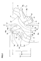
FIG. 2 is an enlarged view of central blocks ofFIG 1 . -
FIG. 3 is an enlarged perspective view of around a recess provided on the central block. -
FIG. 4 is an enlarged plan view of one of the central blocks ofFIG. 1 . -
FIG. 5 is a development view of a tread portion in accordance with an aspect of the reference. - An embodiment of the present invention will be explained below with reference to the accompanying drawings.
FIG. 1 illustrates a development view of atread portion 2 of apneumatic tire 1 in accordance with an embodiment of the present invention. As shown inFIG. 1 , thepneumatic tire 1 in accordance with the present embodiment, for example, is preferably embodied as an all season tire for four-wheel drive vehicle. - The
tread portion 2 is provided with a pair ofcentral block rows 3R arranged on both sides of the tire equator C, and a pair ofshoulder block rows 4R each arranged proximately to each tread edge Te on both sides of the tire equator C. Each of thecentral block rows 3R includes a plurality ofcentral blocks 3 arranged in a circumferential direction of the tire. Each of theshoulder block rows 4R includes a plurality ofshoulder blocks 4 arranged in the circumferential direction of the tire. Thetread portion 2 further includes agroove 5 to define the respectivecentral blocks 3 andshoulder blocks 4. - The tread edges Te refer to axially outermost edges of the ground contacting patch of the
tread portion 2 which occurs under a normally inflated loaded condition when the camber angle of the tire is zero. The normally inflated loaded condition is such that thetire 1 is mounted on a standard wheel rim with a standard pressure and loaded with a standard tire load. - The standard wheel rim is a wheel rim officially approved or recommended for the tire by standards organizations, wherein the standard wheel rim is the "standard rim" specified in JATMA, the "Measuring Rim" in ETRTO, and the "Design Rim" in TRA or the like, for example.
- The standard pressure is a standard pressure officially approved or recommended for the tire by standards organizations, wherein the standard pressure is the "maximum air pressure" in JATMA, the "Inflation Pressure" in ETRTO, and the maximum pressure given in the "Tire Load Limits at Various Cold Inflation Pressures" table in TRA or the like, for example.
- The standard tire load is a tire load officially approved or recommended for the tire by standards organizations, wherein the standard load is the "maximum load capacity" in JATMA, the "Load Capacity" in ETRTO, and the maximum value given in the above-mentioned table in TRA or the like.
- In case of passenger car tires, however, the standard pressure and standard tire load are uniformly defined by 180 kPa and 88 % of the maximum tire load, respectively.
- In this application including specification and claims, various dimensions, positions and the like of the tire refer to those under a normally inflated unloaded condition of the tire unless otherwise noted. The normally inflated unloaded condition is such that the
tire 1 is mounted on the standard wheel rim with the standard pressure but loaded with no tire load. The tread width TW is the width measured under the normally inflated unloaded condition, as the axial distance between the tread edges Te and Te. - Preferably, the
groove 5 has a width W1, which is measured perpendicular to its groove centerline, in a range of from 5% to 15% of the tread width TW, in order to offer sufficient void to improve traction force on mud terrain as well as self-cleaning ability of the tread portion while offering sufficient rigidity of therespective blocks - Each of the
central blocks 3 includes aground contacting face 3a that includes aninner block edge 8 facing the tire equator C, and anouter block edge 9 facing the tread edge Te. - The
inner block edge 8 includes a firstinclined edge 10 and a secondinclined edge 11 inclined in an opposite direction to the firstinclined edge 10 so that theinner block edge 8 protrudes toward the tire equator C. Theinner block edge 8 includes an axial component that may generate traction force during traveling on mud terrain by shearing mud. Furthermore, theinner block edge 8 also includes a circumferential component that may help to smoothly expel mud in thegroove 5 backwardly along theinner block edge 8 during traveling. Thus the self-cleaning ability of thetread portion 2 may be ensured. - As shown in
FIG. 2 , the firstinclined edge 10 in accordance with the present embodiment includes a firstcircular arc portion 12 having a center c1 located on the side of the tire equator C and a secondcircular arc portion 13 having a center c2 located on the side of the tread edge Te. Thus the firstcircular arc portion 12 may introduce a lot of mud into thegroove 5 when coming into contact with mud terrain, thereby generating a large traction force. Furthermore, the secondcircular arc portion 13 may smoothly dispel the mud backwardly from thegroove 5 during traveling. The secondcircular arc portion 13 may enhance rigidity of thecentral block 3 so that a shearing force against mud is improved. - Preferably, the first
circular arc portion 12 has a radius of curvature r1 in a range of from 30 to 60 mm. When the radius of curvature r1 of the firstcircular arc portion 12 is less than 30 mm, mud introduced in thegroove 5 of thetread portion 2 may not be released from thegroove 5 smoothly. When the radius of curvature r1 of the firstcircular arc portion 12 is more than 60 mm, the firstcircular arc portion 12 may not introduce mud into thegroove 5 efficiently. - In this embodiment, the second
circular arc portion 13 is arranged on the side of the secondinclined edge 11 of the firstcircular arc portion 12. Namely, the secondcircular arc portion 13 is arranged on the side of the tire equator C of the firstcircular arc portion 12. Thus the rigidity of an axially inner portion of thecentral blocks 3 may be enhanced so that a larger traction force is generated during straight traveling on mud terrain. - In this embodiment, the second
circular arc portion 13 is configured as a smooth curve including a plurality of connected arcs having different radii. However, it is not particularly limited to the embodiment above. Preferably, the secondcircular arc portion 13 has a radius of curvature r2 in a range of from 30 to 80 mm. - Preferably, the first
inclined edge 10 has a circumferential length larger than that of the secondinclined edge 11. This configuration may help to generate a large traction force on mud terrain. - In this embodiment, the first
inclined edge 10 is configured so that the firstcircular arc portion 12 and the secondcircular arc portion 13 are smoothly connected one another, thereby further improving the self-cleaning ability of thetread portion 2. - In this embodiment, the second
inclined edge 11 includes a thirdcircular arc portion 14 having a center c3 located on the side of the tread edge Te. Thus the secondinclined edge 11 may further enhance the rigidity of the axially inner portion of thecentral blocks 3, thereby increasing traction force. In this embodiment, the whole of the secondinclined edge 11 is configured using the thirdcircular arc portion 14 in order to further improve the advantageous effect described above. - The
corner 15 connecting between the secondinclined edge 11 and the firstinclined edge 10 is formed in an arc manner. This configuration may further enhance the rigidity of the axially inner portion of thecentral blocks 3. - The
central block 3 includes anouter block sidewall 16 extending radially inward from theouter block edge 9 so as to faces the tread edge Te, and aninner block sidewall 17 faces extending radially inward from theinner block edge 8 so as to face the tire equator C. - In this embodiment, the
outer block sidewall 16 includes a firstinclined wall 18, a secondinclined wall 19 inclined so as to cross the firstinclined wall 18, a thirdinclined wall 20 inclined in the same direction to the secondinclined wall 19, and a fourthinclined block wall 21 inclined in an opposite direction to the secondinclined wall 19, in a plan view of thecentral block 3. - The
outer block sidewall 16 is dented toward the tire equator C due to a crossing between the firstinclined wall 18 and the secondinclined wall 19. When theouter block sidewall 16 comes into contact with mud terrain, both of theinclined walls portion 22 so as to compress the mud therebetween, thereby offering a large traction force. On the other hand, when thecentral block 3 is released from the ground due to the tire rotation, the both of theinclined walls walls tread portion 2. Accordingly, theouter block sidewall 16 may further improve the traction force on mud terrain due to the firstinclined wall 18 and the secondinclined wall 19. - In the plan view of the
central block 3, an angle θ between the firstinclined wall 18 and the secondinclined wall 19 is preferably in a range of from 100 to 150 degrees, more preferably in a range of from 110 to 140 degrees. When the angle θ is excessively large, the deformation of the firstinclined wall 18 and the secondinclined wall 19 may be reduced. When the angle θ is excessively small, it may be difficult to remove the mud from between the firstinclined wall 18 and the secondinclined wall 19. - The
ground contacting face 3a is provided with arecess 23 on the crossingportion 22 between the firstinclined wall 18 and the secondinclined wall 19. Such arecess 23 may be useful to grab mud during traveling to help increasing traction force. Furthermore, therecess 23 may reduce the rigidity around the crossingportion 22 of thecentral block 3 so that the deformation of the firstinclined wall 18 and the secondinclined wall 19 during traveling is promoted. - In this embodiment, the
recess 23 is arranged in a circumferentially middle area of thecentral block 3. This design may further promote the deformation of the firstinclined wall 18 and the secondinclined wall 19 during grounding thereby further improving the mud terrain performance of the tire. - Preferably, the
recess 23 has a substantially triangle shape having one corner protruding toward the tire equator C in a plan view of thecentral block 3. Such arecess 23 having a triangle shape may further reduce the rigidity around it of thecentral block 3. Accordingly, the deformation of the firstinclined wall 18 and the secondinclined wall 19 during traveling described above may further be promoted, thereby further improving the mud terrain performance of the tire. - As shown in
FIG. 3 , therecess 23 in accordance with the present embodiment has a depth D1 gradually decreasing toward its axiallyinner end 23a to improve the self-cleaning ability of thetread portion 2. In another aspect, therecess 23 may have the substantially constant depth (not shown). - The depth (maximum depth) D1 of the
recess 23 is preferably in a range of from 50% to 80% of the height Ha of thecentral block 3 in order to ensure the rigidity of thecentral block 3 while improving traction force on mud terrain. - As shown in
FIG. 2 , therecess 23 has an axial length L1 in a range of from 10% to 30% of the axial width Wa of thecentral block 3 in order to further improve the advantageous effects described above. - In the same point of view, the
recess 23 preferably has an area in a range of from 3% to 10% of the gross area of theground contacting face 3a of thecentral block 3 in a plan view of thecentral block 3. Here, the gross area of theground contacting face 3a of thecentral block 3 refers to an area that includes the area of therecess 23. - The third
inclined wall 20 includes asteplike portion 20a that includes a depth varying in a steplike manner in the radial direction of the tire. Thesteplike portion 20a may further increase traction force on mud terrain due to the edge component thereof. - In this embodiment, the
central block 3 includes a firstinclined portion 3A and a secondinclined portion 3B inclined in an opposite direction to the firstinclined portion 3A, wherein the first and secondinclined portions - As shown in
FIG. 2 , the pair ofcentral blocks 3 which are adjacent in the axial direction of the tire are arranged in a point symmetry around a center on the tire equator C. Thus, the secondcircular arc portions - In this embodiment, each of the
central blocks 3 provided on one side of the tire equator C is arranged with respect to each of thecentral blocks 3 provided on the other side of the tire equator C so as to have an overlap region K. The length Lb of the overlap region K in the circumferential direction of the tire is preferably in a range of from 50% to 92% of the maximum circumferential length La of thecentral block 3 in order to improve traction force on mud terrain while ensuring self-cleaning ability of thetread portion 2. - Each of the
central blocks 3 is provided with at least onesipe 25. The at least onesipe 25 may be useful to soften thecentral block 3 so that the deformation of the firstinclined wall 18 and the secondinclined wall 19 during grounding is promoted, thereby further improving the mud terrain performance of the tire. - In this embodiment, the at least one
sipe 25 includes two sipes that includes anouter sipe 26 arranged axially outwardly of thecentral block 3, and an axiallyinner sipe 27 arranged axially inwardly of thecentral block 3 which are not communicated one another. Each of thesipes inner block edge 8 and theouter block edge 9. Thesesipes central block 3 in a well balanced manner to promote the deformation of the firstinclined wall 18 and the secondinclined wall 19. Furthermore, theouter sipe 26 and theinner sipe 27 are arranged separately in the circumferential direction of the tire, for example. - AS shown in
FIG. 4 , in each of thecentral blocks 3, each of thesipe inner sipe 27 has the circumferential component length b1 and the axial component length a1. Similarly, theouter sipe 26 has the circumferential component length b2, b3 and b4 and the axial component length a2, a3 and a4. Preferably, the total circumferential component length B (=b1+b2+b3+b4) of thesipes inclined wall 18 and the secondinclined wall 19 during traveling while ensuring rigidity of thecentral block 3. - As shown in
FIG. 3 , therespective sipe central block 3 and widths W2 of from 0.1 to 0.3 mm. - As shown in
FIG. 1 , at least one of the shoulder blocks 4 includes anouter portion 4a extending along the axial direction of the tire from the tread edge Te and aninner portion 4b inclined in an angle with respect to theouter portion 4a. Furthermore, theshoulder block 4 is provided with alug groove 28 extending from the tread edge Te to its axially inner end and ashoulder sipe 29 extending from the inner end of thelug groove 28 along theinner portion 4b. - While the particularly preferable embodiments of the pneumatic tire in accordance with the present invention have been described in detail, the present invention is not limited to the illustrated embodiments, but can be modified and carried out in various aspects.
- Pneumatic tires for four-wheel drive vehicles having a basic tread pattern shown in
FIG. 1 were manufactured based on the specifications of Table 1, and then mud terrain performance of each tires was tested. Major common specifications of tires and test procedures are as follows. - Tread width TW : 240 mm
- Height of central blocks: 17.1 mm
- Height of shoulder blocks: 17.1 mm
- Each test tire was installed to all wheels of a four-wheel drive vehicle having the displacement of 3,600 cc under the following conditions.
- Tire size: 37x12.50R17
- Rim: 9.0JJ
- Inner pressure: 100 kPa
- Then a test driver drove the vehicle on a test course in mud terrain and evaluated the traction and self-cleaning ability of the tread by his feeling. The results were indicated using a score, wherein the Ref. 1 is scored 100. The larger the score, the better the performance is.
- The test results are shown in Table 1.

- From the test results, it was confirmed that the example tires had excellent mud terrain performance as compared with the reference tire. In another test where tires having a different tire size described above were used, the same results as this test were confirmed.
Claims (10)
- A pneumatic tire comprising:a tread portion having a pair of central block rows arranged on both sides of a tire equator, each of the central block rows comprising a plurality of central blocks arranged in a circumferential direction of the tire;each of the central blocks comprising a ground contacting face having an axially inner block edge facing the tire equator;the inner block edge comprising a first inclined edge and a second inclined edge inclined in an opposite direction to the first inclined edge so that the inner block edge protrudes toward the tire equator; andthe first inclined edge comprising a first circular arc portion having a center located on the side of the tire equator.
- The pneumatic tire according to claim 1,
wherein a radius of curvature of the first circular arc portion is in a range of from 30 to 60 mm. - The pneumatic tire according to claim 1,
wherein the first inclined edge has a circumferential length longer than that of the second inclined edge. - The pneumatic tire according to claim 1,
wherein the first inclined edge further comprises a second circular arc portion having a center located on a side of a tread edge. - The pneumatic tire according to claim 4,
wherein the second circular arc portion is arranged on a side of the second inclined edge of the first circular arc portion. - The pneumatic tire according to claim 1,
wherein each of the central blocks comprises an outer block sidewall facing a tread edge,
the outer block sidewall comprises a first inclined wall and a second inclined wall inclined to cross the first inclined wall so that the outer block sidewall is dented toward the tire equator, and
the ground contacting face is provided with a recess on a portion where the first inclined wall crosses the second inclined wall. - The pneumatic tire according to claim 6,
wherein the recess has a depth in a range of from 50% to 80% of a height of the central block. - The pneumatic tire according to claim 6,
wherein the recess has a substantially triangle shape having one corner protruding toward the tire equator, in a plan view of the central block. - The pneumatic tire according to claim 1,
wherein each of the central blocks provided on one side of the tire equator is arranged with respect to each of the central blocks provided on the other side of the tire equator so as to have an overlap length in the circumferential direction of the tire in a range of from 50% to 92% a circumferential maximum length of the central block. - The pneumatic tire according to claim 1,
wherein each of the central block is provided with at least one sipe having a circumferential component length and an axial component length, and
the circumferential component length is in a range of not less than 45% the total of the circumferential and axial component lengths of the sipe.
Applications Claiming Priority (1)
| Application Number | Priority Date | Filing Date | Title |
|---|---|---|---|
| JP2014083023A JP6010576B2 (en) | 2014-04-14 | 2014-04-14 | Pneumatic tire |
Publications (2)
| Publication Number | Publication Date |
|---|---|
| EP2933120A1 true EP2933120A1 (en) | 2015-10-21 |
| EP2933120B1 EP2933120B1 (en) | 2017-03-08 |
Family
ID=52811061
Family Applications (1)
| Application Number | Title | Priority Date | Filing Date |
|---|---|---|---|
| EP15162748.6A Not-in-force EP2933120B1 (en) | 2014-04-14 | 2015-04-08 | Pneumatic tire |
Country Status (4)
| Country | Link |
|---|---|
| US (1) | US10632795B2 (en) |
| EP (1) | EP2933120B1 (en) |
| JP (1) | JP6010576B2 (en) |
| CN (1) | CN104972844B (en) |
Cited By (3)
| Publication number | Priority date | Publication date | Assignee | Title |
|---|---|---|---|---|
| EP3162595A1 (en) * | 2015-10-29 | 2017-05-03 | Sumitomo Rubber Industries, Ltd. | Pneumatic tire |
| EP3162594A1 (en) * | 2015-10-30 | 2017-05-03 | Sumitomo Rubber Industries, Ltd. | Pneumatic tire |
| CN110234520A (en) * | 2016-12-29 | 2019-09-13 | 倍耐力轮胎股份公司 | car tire |
Families Citing this family (9)
| Publication number | Priority date | Publication date | Assignee | Title |
|---|---|---|---|---|
| CN105172480B (en) * | 2014-05-26 | 2018-09-04 | 住友橡胶工业株式会社 | Pneumatic tire |
| JP6085317B2 (en) * | 2015-01-09 | 2017-02-22 | 住友ゴム工業株式会社 | Pneumatic tire |
| JP6880771B2 (en) | 2017-01-25 | 2021-06-02 | 住友ゴム工業株式会社 | tire |
| JP6891556B2 (en) * | 2017-03-14 | 2021-06-18 | 住友ゴム工業株式会社 | tire |
| JP7069983B2 (en) * | 2017-06-20 | 2022-05-18 | 住友ゴム工業株式会社 | Pneumatic tires |
| CN109094302B (en) | 2017-06-20 | 2022-01-28 | 住友橡胶工业株式会社 | Pneumatic tire |
| JP7095244B2 (en) * | 2017-09-21 | 2022-07-05 | 住友ゴム工業株式会社 | Pneumatic tires |
| CN110509723B (en) * | 2019-10-09 | 2024-07-23 | 厦门正新橡胶工业有限公司 | Agricultural tires |
| TWI876220B (en) * | 2022-10-27 | 2025-03-11 | 正新橡膠工業股份有限公司 | Tire tread structure |
Citations (3)
| Publication number | Priority date | Publication date | Assignee | Title |
|---|---|---|---|---|
| US6065517A (en) * | 1997-01-22 | 2000-05-23 | The Yokohama Rubber Co., Ltd. | Pneumatic radial tire for heavy duty |
| WO2002068222A1 (en) * | 2001-02-28 | 2002-09-06 | Pirelli Pneumatici S.P.A. | Tyre for motor vehicles, with a wide tread, particularly for snow-covered ground |
| JP2008049751A (en) | 2006-08-22 | 2008-03-06 | Toyo Tire & Rubber Co Ltd | Pneumatic tire and manufacturing method thereof |
Family Cites Families (12)
| Publication number | Priority date | Publication date | Assignee | Title |
|---|---|---|---|---|
| DE1213276B (en) * | 1959-05-30 | 1966-03-24 | Continental Gummi Werke Ag | Chunky vehicle tire |
| JPH0295903A (en) * | 1988-10-03 | 1990-04-06 | Bridgestone Corp | Pneumatic tyre for heavy load |
| JP3079026B2 (en) * | 1995-11-15 | 2000-08-21 | 住友ゴム工業株式会社 | studless tire |
| US7048022B2 (en) * | 2003-11-14 | 2006-05-23 | The Goodyear Tire & Rubber Company | Tire tread with anti-puncture pads |
| JP4968895B2 (en) * | 2006-09-25 | 2012-07-04 | 東洋ゴム工業株式会社 | Rough road running pneumatic tire |
| JP4312226B2 (en) * | 2006-11-15 | 2009-08-12 | 住友ゴム工業株式会社 | Pneumatic tire for running on rough terrain |
| US8056592B2 (en) * | 2007-10-31 | 2011-11-15 | The Goodyear Tire + Rubber Company, Inc. | Grip tire with added puncture protection |
| JP5278127B2 (en) * | 2008-06-02 | 2013-09-04 | 横浜ゴム株式会社 | Pneumatic tire |
| JP5314343B2 (en) * | 2008-07-15 | 2013-10-16 | 株式会社ブリヂストン | Pneumatic tire |
| USD627709S1 (en) * | 2010-07-22 | 2010-11-23 | The Goodyear Tire & Rubber Company | Tire |
| WO2012043036A1 (en) * | 2010-09-30 | 2012-04-05 | 株式会社ブリヂストン | Pneumatic tire |
| CN102935789B (en) * | 2012-11-15 | 2015-03-04 | 厦门正新橡胶工业有限公司 | Cross-country tire tread pattern structure |
-
2014
- 2014-04-14 JP JP2014083023A patent/JP6010576B2/en active Active
-
2015
- 2015-03-31 US US14/674,948 patent/US10632795B2/en active Active
- 2015-04-08 EP EP15162748.6A patent/EP2933120B1/en not_active Not-in-force
- 2015-04-09 CN CN201510165809.4A patent/CN104972844B/en not_active Expired - Fee Related
Patent Citations (3)
| Publication number | Priority date | Publication date | Assignee | Title |
|---|---|---|---|---|
| US6065517A (en) * | 1997-01-22 | 2000-05-23 | The Yokohama Rubber Co., Ltd. | Pneumatic radial tire for heavy duty |
| WO2002068222A1 (en) * | 2001-02-28 | 2002-09-06 | Pirelli Pneumatici S.P.A. | Tyre for motor vehicles, with a wide tread, particularly for snow-covered ground |
| JP2008049751A (en) | 2006-08-22 | 2008-03-06 | Toyo Tire & Rubber Co Ltd | Pneumatic tire and manufacturing method thereof |
Cited By (5)
| Publication number | Priority date | Publication date | Assignee | Title |
|---|---|---|---|---|
| EP3162595A1 (en) * | 2015-10-29 | 2017-05-03 | Sumitomo Rubber Industries, Ltd. | Pneumatic tire |
| EP3162594A1 (en) * | 2015-10-30 | 2017-05-03 | Sumitomo Rubber Industries, Ltd. | Pneumatic tire |
| CN110234520A (en) * | 2016-12-29 | 2019-09-13 | 倍耐力轮胎股份公司 | car tire |
| CN110234520B (en) * | 2016-12-29 | 2022-03-01 | 倍耐力轮胎股份公司 | Automobile tyre |
| US11858295B2 (en) | 2016-12-29 | 2024-01-02 | Pirelli Tyre S.P.A. | Car tyre |
Also Published As
| Publication number | Publication date |
|---|---|
| CN104972844A (en) | 2015-10-14 |
| EP2933120B1 (en) | 2017-03-08 |
| CN104972844B (en) | 2018-06-19 |
| US10632795B2 (en) | 2020-04-28 |
| US20150290977A1 (en) | 2015-10-15 |
| JP6010576B2 (en) | 2016-10-19 |
| JP2015202776A (en) | 2015-11-16 |
Similar Documents
| Publication | Publication Date | Title |
|---|---|---|
| EP2933120B1 (en) | Pneumatic tire | |
| US10710415B2 (en) | Tire | |
| US9994077B2 (en) | Pneumatic tire | |
| US10391819B2 (en) | Pneumatic tire | |
| EP3000622B1 (en) | Pneumatic tire | |
| US10696102B2 (en) | Tire | |
| EP3162594B1 (en) | Pneumatic tire | |
| EP3015286A1 (en) | Pneumatic tire | |
| US10471777B2 (en) | Pneumatic tire | |
| JP6014092B2 (en) | Pneumatic tire | |
| US9096099B2 (en) | Pneumatic tire | |
| EP2664464A1 (en) | Pneumatic tire | |
| EP3162595B1 (en) | Pneumatic tire | |
| EP3375633A1 (en) | Tire | |
| US9731560B2 (en) | Pneumatic tire | |
| US11021018B2 (en) | Tire | |
| JP7306163B2 (en) | tire | |
| JP2017128269A (en) | Pneumatic tire | |
| US10427469B2 (en) | Pneumatic tire | |
| US11135877B2 (en) | Tire | |
| JP7298369B2 (en) | tire | |
| EP3643526B1 (en) | Tire | |
| CN108688413A (en) | tire | |
| JP7139860B2 (en) | tire | |
| JP7815745B2 (en) | tire |
Legal Events
| Date | Code | Title | Description |
|---|---|---|---|
| PUAI | Public reference made under article 153(3) epc to a published international application that has entered the european phase |
Free format text: ORIGINAL CODE: 0009012 |
|
| AK | Designated contracting states |
Kind code of ref document: A1 Designated state(s): AL AT BE BG CH CY CZ DE DK EE ES FI FR GB GR HR HU IE IS IT LI LT LU LV MC MK MT NL NO PL PT RO RS SE SI SK SM TR |
|
| AX | Request for extension of the european patent |
Extension state: BA ME |
|
| 17P | Request for examination filed |
Effective date: 20160127 |
|
| RBV | Designated contracting states (corrected) |
Designated state(s): AL AT BE BG CH CY CZ DE DK EE ES FI FR GB GR HR HU IE IS IT LI LT LU LV MC MK MT NL NO PL PT RO RS SE SI SK SM TR |
|
| RIC1 | Information provided on ipc code assigned before grant |
Ipc: B60C 11/03 20060101AFI20161006BHEP Ipc: B60C 11/13 20060101ALI20161006BHEP Ipc: B60C 11/11 20060101ALI20161006BHEP Ipc: B60C 11/12 20060101ALI20161006BHEP |
|
| GRAP | Despatch of communication of intention to grant a patent |
Free format text: ORIGINAL CODE: EPIDOSNIGR1 |
|
| STAA | Information on the status of an ep patent application or granted ep patent |
Free format text: STATUS: GRANT OF PATENT IS INTENDED |
|
| INTG | Intention to grant announced |
Effective date: 20161115 |
|
| GRAS | Grant fee paid |
Free format text: ORIGINAL CODE: EPIDOSNIGR3 |
|
| GRAA | (expected) grant |
Free format text: ORIGINAL CODE: 0009210 |
|
| STAA | Information on the status of an ep patent application or granted ep patent |
Free format text: STATUS: THE PATENT HAS BEEN GRANTED |
|
| AK | Designated contracting states |
Kind code of ref document: B1 Designated state(s): AL AT BE BG CH CY CZ DE DK EE ES FI FR GB GR HR HU IE IS IT LI LT LU LV MC MK MT NL NO PL PT RO RS SE SI SK SM TR |
|
| REG | Reference to a national code |
Ref country code: GB Ref legal event code: FG4D |
|
| REG | Reference to a national code |
Ref country code: CH Ref legal event code: EP Ref country code: AT Ref legal event code: REF Ref document number: 873189 Country of ref document: AT Kind code of ref document: T Effective date: 20170315 |
|
| REG | Reference to a national code |
Ref country code: IE Ref legal event code: FG4D |
|
| REG | Reference to a national code |
Ref country code: FR Ref legal event code: PLFP Year of fee payment: 3 |
|
| REG | Reference to a national code |
Ref country code: DE Ref legal event code: R096 Ref document number: 602015001702 Country of ref document: DE |
|
| REG | Reference to a national code |
Ref country code: LT Ref legal event code: MG4D |
|
| REG | Reference to a national code |
Ref country code: NL Ref legal event code: MP Effective date: 20170308 |
|
| PG25 | Lapsed in a contracting state [announced via postgrant information from national office to epo] |
Ref country code: FI Free format text: LAPSE BECAUSE OF FAILURE TO SUBMIT A TRANSLATION OF THE DESCRIPTION OR TO PAY THE FEE WITHIN THE PRESCRIBED TIME-LIMIT Effective date: 20170308 Ref country code: HR Free format text: LAPSE BECAUSE OF FAILURE TO SUBMIT A TRANSLATION OF THE DESCRIPTION OR TO PAY THE FEE WITHIN THE PRESCRIBED TIME-LIMIT Effective date: 20170308 Ref country code: NO Free format text: LAPSE BECAUSE OF FAILURE TO SUBMIT A TRANSLATION OF THE DESCRIPTION OR TO PAY THE FEE WITHIN THE PRESCRIBED TIME-LIMIT Effective date: 20170608 Ref country code: GR Free format text: LAPSE BECAUSE OF FAILURE TO SUBMIT A TRANSLATION OF THE DESCRIPTION OR TO PAY THE FEE WITHIN THE PRESCRIBED TIME-LIMIT Effective date: 20170609 Ref country code: LT Free format text: LAPSE BECAUSE OF FAILURE TO SUBMIT A TRANSLATION OF THE DESCRIPTION OR TO PAY THE FEE WITHIN THE PRESCRIBED TIME-LIMIT Effective date: 20170308 |
|
| REG | Reference to a national code |
Ref country code: AT Ref legal event code: MK05 Ref document number: 873189 Country of ref document: AT Kind code of ref document: T Effective date: 20170308 |
|
| PG25 | Lapsed in a contracting state [announced via postgrant information from national office to epo] |
Ref country code: RS Free format text: LAPSE BECAUSE OF FAILURE TO SUBMIT A TRANSLATION OF THE DESCRIPTION OR TO PAY THE FEE WITHIN THE PRESCRIBED TIME-LIMIT Effective date: 20170308 Ref country code: SE Free format text: LAPSE BECAUSE OF FAILURE TO SUBMIT A TRANSLATION OF THE DESCRIPTION OR TO PAY THE FEE WITHIN THE PRESCRIBED TIME-LIMIT Effective date: 20170308 Ref country code: ES Free format text: LAPSE BECAUSE OF FAILURE TO SUBMIT A TRANSLATION OF THE DESCRIPTION OR TO PAY THE FEE WITHIN THE PRESCRIBED TIME-LIMIT Effective date: 20170308 Ref country code: BG Free format text: LAPSE BECAUSE OF FAILURE TO SUBMIT A TRANSLATION OF THE DESCRIPTION OR TO PAY THE FEE WITHIN THE PRESCRIBED TIME-LIMIT Effective date: 20170608 Ref country code: LV Free format text: LAPSE BECAUSE OF FAILURE TO SUBMIT A TRANSLATION OF THE DESCRIPTION OR TO PAY THE FEE WITHIN THE PRESCRIBED TIME-LIMIT Effective date: 20170308 |
|
| PG25 | Lapsed in a contracting state [announced via postgrant information from national office to epo] |
Ref country code: NL Free format text: LAPSE BECAUSE OF FAILURE TO SUBMIT A TRANSLATION OF THE DESCRIPTION OR TO PAY THE FEE WITHIN THE PRESCRIBED TIME-LIMIT Effective date: 20170308 |
|
| PG25 | Lapsed in a contracting state [announced via postgrant information from national office to epo] |
Ref country code: SK Free format text: LAPSE BECAUSE OF FAILURE TO SUBMIT A TRANSLATION OF THE DESCRIPTION OR TO PAY THE FEE WITHIN THE PRESCRIBED TIME-LIMIT Effective date: 20170308 Ref country code: EE Free format text: LAPSE BECAUSE OF FAILURE TO SUBMIT A TRANSLATION OF THE DESCRIPTION OR TO PAY THE FEE WITHIN THE PRESCRIBED TIME-LIMIT Effective date: 20170308 Ref country code: IT Free format text: LAPSE BECAUSE OF FAILURE TO SUBMIT A TRANSLATION OF THE DESCRIPTION OR TO PAY THE FEE WITHIN THE PRESCRIBED TIME-LIMIT Effective date: 20170308 Ref country code: RO Free format text: LAPSE BECAUSE OF FAILURE TO SUBMIT A TRANSLATION OF THE DESCRIPTION OR TO PAY THE FEE WITHIN THE PRESCRIBED TIME-LIMIT Effective date: 20170308 Ref country code: AT Free format text: LAPSE BECAUSE OF FAILURE TO SUBMIT A TRANSLATION OF THE DESCRIPTION OR TO PAY THE FEE WITHIN THE PRESCRIBED TIME-LIMIT Effective date: 20170308 Ref country code: CZ Free format text: LAPSE BECAUSE OF FAILURE TO SUBMIT A TRANSLATION OF THE DESCRIPTION OR TO PAY THE FEE WITHIN THE PRESCRIBED TIME-LIMIT Effective date: 20170308 |
|
| PG25 | Lapsed in a contracting state [announced via postgrant information from national office to epo] |
Ref country code: IS Free format text: LAPSE BECAUSE OF FAILURE TO SUBMIT A TRANSLATION OF THE DESCRIPTION OR TO PAY THE FEE WITHIN THE PRESCRIBED TIME-LIMIT Effective date: 20170708 Ref country code: PT Free format text: LAPSE BECAUSE OF FAILURE TO SUBMIT A TRANSLATION OF THE DESCRIPTION OR TO PAY THE FEE WITHIN THE PRESCRIBED TIME-LIMIT Effective date: 20170710 Ref country code: PL Free format text: LAPSE BECAUSE OF FAILURE TO SUBMIT A TRANSLATION OF THE DESCRIPTION OR TO PAY THE FEE WITHIN THE PRESCRIBED TIME-LIMIT Effective date: 20170308 Ref country code: SM Free format text: LAPSE BECAUSE OF FAILURE TO SUBMIT A TRANSLATION OF THE DESCRIPTION OR TO PAY THE FEE WITHIN THE PRESCRIBED TIME-LIMIT Effective date: 20170308 |
|
| REG | Reference to a national code |
Ref country code: DE Ref legal event code: R097 Ref document number: 602015001702 Country of ref document: DE |
|
| PLBE | No opposition filed within time limit |
Free format text: ORIGINAL CODE: 0009261 |
|
| STAA | Information on the status of an ep patent application or granted ep patent |
Free format text: STATUS: NO OPPOSITION FILED WITHIN TIME LIMIT |
|
| REG | Reference to a national code |
Ref country code: IE Ref legal event code: MM4A |
|
| PG25 | Lapsed in a contracting state [announced via postgrant information from national office to epo] |
Ref country code: MC Free format text: LAPSE BECAUSE OF FAILURE TO SUBMIT A TRANSLATION OF THE DESCRIPTION OR TO PAY THE FEE WITHIN THE PRESCRIBED TIME-LIMIT Effective date: 20170308 Ref country code: DK Free format text: LAPSE BECAUSE OF FAILURE TO SUBMIT A TRANSLATION OF THE DESCRIPTION OR TO PAY THE FEE WITHIN THE PRESCRIBED TIME-LIMIT Effective date: 20170308 |
|
| 26N | No opposition filed |
Effective date: 20171211 |
|
| PG25 | Lapsed in a contracting state [announced via postgrant information from national office to epo] |
Ref country code: SI Free format text: LAPSE BECAUSE OF FAILURE TO SUBMIT A TRANSLATION OF THE DESCRIPTION OR TO PAY THE FEE WITHIN THE PRESCRIBED TIME-LIMIT Effective date: 20170308 Ref country code: LU Free format text: LAPSE BECAUSE OF NON-PAYMENT OF DUE FEES Effective date: 20170408 |
|
| REG | Reference to a national code |
Ref country code: FR Ref legal event code: PLFP Year of fee payment: 4 |
|
| REG | Reference to a national code |
Ref country code: BE Ref legal event code: MM Effective date: 20170430 |
|
| PG25 | Lapsed in a contracting state [announced via postgrant information from national office to epo] |
Ref country code: IE Free format text: LAPSE BECAUSE OF NON-PAYMENT OF DUE FEES Effective date: 20170408 |
|
| PG25 | Lapsed in a contracting state [announced via postgrant information from national office to epo] |
Ref country code: BE Free format text: LAPSE BECAUSE OF NON-PAYMENT OF DUE FEES Effective date: 20170430 |
|
| PG25 | Lapsed in a contracting state [announced via postgrant information from national office to epo] |
Ref country code: MT Free format text: LAPSE BECAUSE OF NON-PAYMENT OF DUE FEES Effective date: 20170408 |
|
| REG | Reference to a national code |
Ref country code: CH Ref legal event code: PL |
|
| PG25 | Lapsed in a contracting state [announced via postgrant information from national office to epo] |
Ref country code: CH Free format text: LAPSE BECAUSE OF NON-PAYMENT OF DUE FEES Effective date: 20180430 Ref country code: LI Free format text: LAPSE BECAUSE OF NON-PAYMENT OF DUE FEES Effective date: 20180430 |
|
| PG25 | Lapsed in a contracting state [announced via postgrant information from national office to epo] |
Ref country code: HU Free format text: LAPSE BECAUSE OF FAILURE TO SUBMIT A TRANSLATION OF THE DESCRIPTION OR TO PAY THE FEE WITHIN THE PRESCRIBED TIME-LIMIT; INVALID AB INITIO Effective date: 20150408 |
|
| PG25 | Lapsed in a contracting state [announced via postgrant information from national office to epo] |
Ref country code: CY Free format text: LAPSE BECAUSE OF FAILURE TO SUBMIT A TRANSLATION OF THE DESCRIPTION OR TO PAY THE FEE WITHIN THE PRESCRIBED TIME-LIMIT Effective date: 20170308 |
|
| PG25 | Lapsed in a contracting state [announced via postgrant information from national office to epo] |
Ref country code: MK Free format text: LAPSE BECAUSE OF FAILURE TO SUBMIT A TRANSLATION OF THE DESCRIPTION OR TO PAY THE FEE WITHIN THE PRESCRIBED TIME-LIMIT Effective date: 20170308 |
|
| GBPC | Gb: european patent ceased through non-payment of renewal fee |
Effective date: 20190408 |
|
| PG25 | Lapsed in a contracting state [announced via postgrant information from national office to epo] |
Ref country code: GB Free format text: LAPSE BECAUSE OF NON-PAYMENT OF DUE FEES Effective date: 20190408 |
|
| PG25 | Lapsed in a contracting state [announced via postgrant information from national office to epo] |
Ref country code: TR Free format text: LAPSE BECAUSE OF FAILURE TO SUBMIT A TRANSLATION OF THE DESCRIPTION OR TO PAY THE FEE WITHIN THE PRESCRIBED TIME-LIMIT Effective date: 20170308 |
|
| PG25 | Lapsed in a contracting state [announced via postgrant information from national office to epo] |
Ref country code: AL Free format text: LAPSE BECAUSE OF FAILURE TO SUBMIT A TRANSLATION OF THE DESCRIPTION OR TO PAY THE FEE WITHIN THE PRESCRIBED TIME-LIMIT Effective date: 20170308 |
|
| P01 | Opt-out of the competence of the unified patent court (upc) registered |
Effective date: 20230510 |
|
| PGFP | Annual fee paid to national office [announced via postgrant information from national office to epo] |
Ref country code: FR Payment date: 20240308 Year of fee payment: 10 |
|
| PGFP | Annual fee paid to national office [announced via postgrant information from national office to epo] |
Ref country code: DE Payment date: 20240227 Year of fee payment: 10 |
|
| REG | Reference to a national code |
Ref country code: DE Ref legal event code: R119 Ref document number: 602015001702 Country of ref document: DE |
|
| PG25 | Lapsed in a contracting state [announced via postgrant information from national office to epo] |
Ref country code: DE Free format text: LAPSE BECAUSE OF NON-PAYMENT OF DUE FEES Effective date: 20251104 |
|
| PG25 | Lapsed in a contracting state [announced via postgrant information from national office to epo] |
Ref country code: FR Free format text: LAPSE BECAUSE OF NON-PAYMENT OF DUE FEES Effective date: 20250430 |