EP2932882A1 - Fluorescent observation device - Google Patents
Fluorescent observation device Download PDFInfo
- Publication number
- EP2932882A1 EP2932882A1 EP13863259.1A EP13863259A EP2932882A1 EP 2932882 A1 EP2932882 A1 EP 2932882A1 EP 13863259 A EP13863259 A EP 13863259A EP 2932882 A1 EP2932882 A1 EP 2932882A1
- Authority
- EP
- European Patent Office
- Prior art keywords
- fluorescence
- image
- region
- generating portion
- motion
- Prior art date
- Legal status (The legal status is an assumption and is not a legal conclusion. Google has not performed a legal analysis and makes no representation as to the accuracy of the status listed.)
- Withdrawn
Links
Images





Classifications
-
- G—PHYSICS
- G01—MEASURING; TESTING
- G01N—INVESTIGATING OR ANALYSING MATERIALS BY DETERMINING THEIR CHEMICAL OR PHYSICAL PROPERTIES
- G01N21/00—Investigating or analysing materials by the use of optical means, i.e. using sub-millimetre waves, infrared, visible or ultraviolet light
- G01N21/62—Systems in which the material investigated is excited whereby it emits light or causes a change in wavelength of the incident light
- G01N21/63—Systems in which the material investigated is excited whereby it emits light or causes a change in wavelength of the incident light optically excited
- G01N21/64—Fluorescence; Phosphorescence
- G01N21/645—Specially adapted constructive features of fluorimeters
- G01N21/6456—Spatial resolved fluorescence measurements; Imaging
-
- A—HUMAN NECESSITIES
- A61—MEDICAL OR VETERINARY SCIENCE; HYGIENE
- A61B—DIAGNOSIS; SURGERY; IDENTIFICATION
- A61B1/00—Instruments for performing medical examinations of the interior of cavities or tubes of the body by visual or photographical inspection, e.g. endoscopes; Illuminating arrangements therefor
- A61B1/00002—Operational features of endoscopes
- A61B1/00004—Operational features of endoscopes characterised by electronic signal processing
- A61B1/00009—Operational features of endoscopes characterised by electronic signal processing of image signals during a use of endoscope
-
- A—HUMAN NECESSITIES
- A61—MEDICAL OR VETERINARY SCIENCE; HYGIENE
- A61B—DIAGNOSIS; SURGERY; IDENTIFICATION
- A61B1/00—Instruments for performing medical examinations of the interior of cavities or tubes of the body by visual or photographical inspection, e.g. endoscopes; Illuminating arrangements therefor
- A61B1/00002—Operational features of endoscopes
- A61B1/00004—Operational features of endoscopes characterised by electronic signal processing
- A61B1/00009—Operational features of endoscopes characterised by electronic signal processing of image signals during a use of endoscope
- A61B1/000094—Operational features of endoscopes characterised by electronic signal processing of image signals during a use of endoscope extracting biological structures
-
- A—HUMAN NECESSITIES
- A61—MEDICAL OR VETERINARY SCIENCE; HYGIENE
- A61B—DIAGNOSIS; SURGERY; IDENTIFICATION
- A61B1/00—Instruments for performing medical examinations of the interior of cavities or tubes of the body by visual or photographical inspection, e.g. endoscopes; Illuminating arrangements therefor
- A61B1/04—Instruments for performing medical examinations of the interior of cavities or tubes of the body by visual or photographical inspection, e.g. endoscopes; Illuminating arrangements therefor combined with photographic or television appliances
- A61B1/043—Instruments for performing medical examinations of the interior of cavities or tubes of the body by visual or photographical inspection, e.g. endoscopes; Illuminating arrangements therefor combined with photographic or television appliances for fluorescence imaging
-
- A—HUMAN NECESSITIES
- A61—MEDICAL OR VETERINARY SCIENCE; HYGIENE
- A61B—DIAGNOSIS; SURGERY; IDENTIFICATION
- A61B1/00—Instruments for performing medical examinations of the interior of cavities or tubes of the body by visual or photographical inspection, e.g. endoscopes; Illuminating arrangements therefor
- A61B1/06—Instruments for performing medical examinations of the interior of cavities or tubes of the body by visual or photographical inspection, e.g. endoscopes; Illuminating arrangements therefor with illuminating arrangements
- A61B1/0638—Instruments for performing medical examinations of the interior of cavities or tubes of the body by visual or photographical inspection, e.g. endoscopes; Illuminating arrangements therefor with illuminating arrangements providing two or more wavelengths
-
- G—PHYSICS
- G02—OPTICS
- G02B—OPTICAL ELEMENTS, SYSTEMS OR APPARATUS
- G02B21/00—Microscopes
- G02B21/16—Microscopes adapted for ultraviolet illumination ; Fluorescence microscopes
-
- G—PHYSICS
- G02—OPTICS
- G02B—OPTICAL ELEMENTS, SYSTEMS OR APPARATUS
- G02B23/00—Telescopes, e.g. binoculars; Periscopes; Instruments for viewing the inside of hollow bodies; Viewfinders; Optical aiming or sighting devices
- G02B23/24—Instruments or systems for viewing the inside of hollow bodies, e.g. fibrescopes
- G02B23/2407—Optical details
- G02B23/2423—Optical details of the distal end
-
- G—PHYSICS
- G02—OPTICS
- G02B—OPTICAL ELEMENTS, SYSTEMS OR APPARATUS
- G02B23/00—Telescopes, e.g. binoculars; Periscopes; Instruments for viewing the inside of hollow bodies; Viewfinders; Optical aiming or sighting devices
- G02B23/24—Instruments or systems for viewing the inside of hollow bodies, e.g. fibrescopes
- G02B23/26—Instruments or systems for viewing the inside of hollow bodies, e.g. fibrescopes using light guides
-
- G—PHYSICS
- G06—COMPUTING OR CALCULATING; COUNTING
- G06T—IMAGE DATA PROCESSING OR GENERATION, IN GENERAL
- G06T5/00—Image enhancement or restoration
- G06T5/50—Image enhancement or restoration using two or more images, e.g. averaging or subtraction
-
- G—PHYSICS
- G01—MEASURING; TESTING
- G01N—INVESTIGATING OR ANALYSING MATERIALS BY DETERMINING THEIR CHEMICAL OR PHYSICAL PROPERTIES
- G01N21/00—Investigating or analysing materials by the use of optical means, i.e. using sub-millimetre waves, infrared, visible or ultraviolet light
- G01N21/62—Systems in which the material investigated is excited whereby it emits light or causes a change in wavelength of the incident light
- G01N21/63—Systems in which the material investigated is excited whereby it emits light or causes a change in wavelength of the incident light optically excited
- G01N21/64—Fluorescence; Phosphorescence
- G01N21/645—Specially adapted constructive features of fluorimeters
- G01N2021/6463—Optics
- G01N2021/6471—Special filters, filter wheel
-
- G—PHYSICS
- G01—MEASURING; TESTING
- G01N—INVESTIGATING OR ANALYSING MATERIALS BY DETERMINING THEIR CHEMICAL OR PHYSICAL PROPERTIES
- G01N2201/00—Features of devices classified in G01N21/00
- G01N2201/06—Illumination; Optics
- G01N2201/061—Sources
-
- G—PHYSICS
- G06—COMPUTING OR CALCULATING; COUNTING
- G06T—IMAGE DATA PROCESSING OR GENERATION, IN GENERAL
- G06T2207/00—Indexing scheme for image analysis or image enhancement
- G06T2207/10—Image acquisition modality
- G06T2207/10064—Fluorescence image
-
- G—PHYSICS
- G06—COMPUTING OR CALCULATING; COUNTING
- G06T—IMAGE DATA PROCESSING OR GENERATION, IN GENERAL
- G06T2207/00—Indexing scheme for image analysis or image enhancement
- G06T2207/10—Image acquisition modality
- G06T2207/10068—Endoscopic image
-
- G—PHYSICS
- G06—COMPUTING OR CALCULATING; COUNTING
- G06T—IMAGE DATA PROCESSING OR GENERATION, IN GENERAL
- G06T2207/00—Indexing scheme for image analysis or image enhancement
- G06T2207/20—Special algorithmic details
- G06T2207/20212—Image combination
- G06T2207/20221—Image fusion; Image merging
Definitions
- the present invention relates to a fluorescence observation apparatus.
- the fluorescence image is added to any of a red-component image, a green-component image, and a blue-component image constituting the color reference image to thereby display the lesion as a red, green, or blue region on the reference image.
- the reference image includes information on original gradation values, i.e. information on the morphology of the subject, in a region displaying the lesion, there is an advantage that the morphology of the lesion can also be observed.
- the region of the lesion in the reference image is filled with a false color. In this case, although there is an advantage that the visibility of the lesion will be improved, there is a disadvantage that observation of the morphology of the lesion within the reference image is impeded by the false color.
- the present invention was conceived in view of the above-described circumstances, and an object thereof is to provide a fluorescence observation apparatus that can display a lesion on a reference image with excellent visibility without impeding observation of the lesion using the reference image.
- the present invention provides the following solutions.
- the present invention provides a fluorescence observation apparatus including: a light source that irradiates a subject with reference light and excitation light; a fluorescence-image generating portion that captures fluorescence produced in the subject due to irradiation with the excitation light from the light source to generate a fluorescence image; a reference-image generating portion that captures return light returning from the subject due to irradiation with the reference light from the light source to generate a color reference image; an extraction portion that extracts, from the fluorescence image generated by the fluorescence-image generating portion, a fluorescence region having a gradation value equal to or higher than a prescribed threshold; a motion-effect generating portion that generates a frame image that is assigned a time-varying gradation value so as to bring about an effect that is visually time-varying with a variation quantity depending on a gradation value of the fluorescence region, in a region corresponding to the fluorescence region extracted by the extraction portion; and a synthesis portion that adds
- the reference image in which the morphology of the subject is captured by irradiating the subject with reference light from the light source is acquired by the reference-image generating portion.
- the fluorescence image in which fluorescence from a lesion present in the subject is captured with irradiation of excitation light from the light source is acquired by the fluorescence-image generating portion.
- the lesion within the fluorescence image is extracted as a fluorescence region by the extraction portion.
- the frame image having a gradation value is generated, by a motion-effect generating portion, in the region within the reference image corresponding to the extracted lesion.
- the frame image is added to a color-component image constituting the reference image by a synthesis portion, to thereby synthesize the synthetic image displaying the lesion on the reference image.
- the lesion in the lesion within continuously-displayed synthetic images, a motion effect is caused by time-dependent variation of the gradation value with a variation quantity set depending on an intensity of fluorescence from the lesion. Therefore, the lesion can be displayed on the reference image with excellent visibility.
- the synthetic image includes information on gradation values possessed by color-component images constituting the reference image, i.e., information on the morphology of the subject, within the region of lesion. Therefore, observation of the lesion using the reference image can also be carried out.
- a coefficient-calculating portion that calculates a coefficient, which increases with an increase of the gradation value of the fluorescence region, based on said gradation value may be provided, and the motion-effect generating portion may determine the variation quantity based on the coefficient calculated by the coefficient-calculating portion.
- the motion-effect generating portion may generate the frame image that brings about an effect causing the predetermined object to move within the corresponding region at a speed depending on the gradation value of the fluorescence region.
- This provides an effect causing a predetermined object to move in the lesion within the synthetic image.
- the observer can intuitively and easily recognize the pathological severity of the lesion from the speed of movement of the object.
- the motion-effect generating portion may generate the frame image that brings about an effect causing a predetermined object to move within the corresponding region with an amplitude depending on the gradation value of the fluorescence region.
- This provides an effect causing the predetermined object to move in the lesion within the synthetic image.
- the observer can intuitively and easily recognize the pathological severity of the lesion from the amplitude of movement of the object.
- the motion-effect generating portion may generate the frame image that brings about an effect causing a color to vary with a period depending on the gradation value of the fluorescence region.
- the motion-effect generating portion may generate the frame image that brings about an effect causing a color to vary with a range depending on the gradation value of the fluorescence region.
- a movement-quantity detecting portion that detects a movement quantity of the subject in the reference image
- the motion-effect generating portion may provide a variation effect with a variation quantity depending on a value obtained by adding the movement quantity of the subject detected by the movement-quantity detecting portion to the gradation value of the fluorescence region.
- a fluorescence-correcting portion that divides the fluorescence image generated by the fluorescence-image generating portion by the reference image generated by the reference-image generating portion to thereby correct the gradation value of the fluorescence image may be provided, and the extraction portion may extract the fluorescence region from the fluorescence image corrected by the fluorescence-correcting portion.
- a corrected fluorescence image By use of such a corrected fluorescence image, the lesion can more accurately be extracted. Furthermore, a motion effect of more accurately representing the pathological severity of the lesion can be imparted to the lesion.
- a threshold-setting portion that sets the prescribed threshold in the extraction portion based on a sum of a mean of gradation values of respective pixels in the fluorescence image corrected by the fluorescence-correcting portion and a standard deviation of the gradation values may be provided.
- the present invention affords the advantage that it is possible to display a lesion on a reference image with excellent visibility without impeding observation of the lesion using the reference image.
- a fluorescence observation apparatus 1 according to one embodiment of the present invention will be described below with reference to Figs. 1 to 5 .
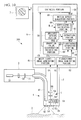
- the fluorescence observation apparatus 1 is an endoscopic apparatus. As shown in Fig. 1 , the fluorescence observation apparatus 1 includes an elongated insertion portion 2 that is inserted into a body; a light source 3; an illumination unit 4 that radiates excitation light and white light (reference light) from the light source 3 from a distal end 2a of the insertion portion 2 toward a subject X; an image-acquisition unit 5 that is provided in the distal end 2a of the insertion portion 2 and that acquires image information S1 and S2 of the subject X; an image-processing unit 6 that is disposed at the base end of the insertion portion 2 and that processes the image information S1 and S2 acquired by the image-acquisition unit 5; and a display portion 7 that displays an image G which has been processed by the image-processing unit 6.
- the light source 3 includes a xenon lamp 31; a filter 32 that extracts excitation light and white light from the light emitted from the xenon lamp 31; and a coupling lens 33 that focuses the excitation light and the white light extracted by the filter 32.
- the filter 32 selectively transmits light with a wavelength band of 400 nm to 740 nm corresponding to the excitation light and white light.
- near-infrared light e.g. a wavelength band of 700 nm to 740 nm
- the excitation light in this embodiment.
- the illumination unit 4 includes a light guide fiber 41 that is disposed along almost the entire length in the longitudinal direction of the insertion portion 2 and an illumination optical system 42 that is provided at the distal end 2a of the insertion portion 2.
- the light guide fiber 41 guides the excitation light and the white light focused by the coupling lens 33.
- the illumination optical system 42 spreads out the excitation light and the white light that have been guided by the light guide fiber 41, and radiates them onto the subject X that faces the distal end 2a of the insertion portion 2.
- the image-acquisition unit 5 includes an objective lens 51 that collects light from the subject X; a dichroic mirror 52 that reflects excitation light and fluorescence among the light collected by the objective lens 51 and that transmits white light (with a wavelength band of 400 nm to 700 nm; return light) having a wavelength shorter than that of the excitation light; two focusing lenses 53 and 54 that respectively focus the fluorescence reflected by the dichroic mirror 52 and the white light transmitted through the dichroic mirror 52; an image-acquisition device 55, such as a color CCD, that captures the white light focused by the focusing lens 54; and an image-acquisition device 56, such as a highly sensitive monochrome CCD, that captures the fluorescence focused by the focusing lens 53.
- an objective lens 51 that collects light from the subject X
- a dichroic mirror 52 that reflects excitation light and fluorescence among the light collected by the objective lens 51 and that transmits white light (with a wavelength band of 400 nm to 700 nm; return light
- reference sign 57 refers to an excitation-light cutting filter that selectively transmits fluorescence (e.g., a wavelength band of 760 nm to 850 nm) among the light reflected by the dichroic mirror 52 and that blocks excitation light.
- fluorescence e.g., a wavelength band of 760 nm to 850 nm
- a white-light image G1 and a fluorescence image G2 can simultaneously be acquired, for example, by administering an anti-CEA antibody labeled with a fluorescent dye Cy7 to the subject X, followed by observation.
- CEA is a protein that is expressed specifically in cancer.
- the image-processing unit 6 includes a white-light-image generating portion (reference-image generating portion) 61 that generates a white-light image (reference image) G1 from white-light image information S1 acquired by the image-acquisition device 55; a fluorescence-image generating portion 62 that generates a fluorescence image G2 from fluorescence image information S2 acquired by the image-acquisition device 56; an extraction portion 63 that extracts a fluorescence region F from the fluorescence image G2 generated by the fluorescence-image generating portion 62; a coefficient-calculating portion 64 that calculates a coefficient c for generation of a frame image Gf described below by use of a gradation value of the fluorescence region F extracted by the extraction portion 63; a motion-effect generating portion 65 that generates a frame image Gf time-varying at the position of the fluorescence region F; and a synthesis portion 66 that adds the frame image Gf generated by the motion-effect generating portion 65 to the white-light image G
- the extraction portion 63 compares the gradation value of each pixel of the fluorescence image G2 input from the fluorescence-image generating portion 62 with a prescribed threshold S, and extracts pixels having a gradation value equal to or higher than the prescribed threshold S as a fluorescence region F, as shown in (b) of Fig. 2 .
- the extraction portion 63 outputs gradation values of the extracted pixels to the coefficient-calculating portion 64 and outputs positions of the extracted pixels to the motion-effect generating portion 65.
- the coefficient-calculating portion 64 calculates a mean m of gradation values of pixels, constituting the fluorescence region F, that have been input by the extraction portion 63, calculates a coefficient c based on the calculated mean m, and outputs the calculated coefficient c to the motion-effect generating portion 65.
- the coefficient c is set as a function that increases with an increase of the mean m, for example, a function proportional to the mean m.
- the coefficient-calculating portion 64 may calculate the coefficient c by use of a median or mode of gradation values of pixels extracted by the extraction portion 63, instead of using the mean m.
- the motion-effect generating portion 65 has a clock that counts time t.
- the motion-effect generating portion 65 generates the frame image Gf constituting an animation that moves with a motion quantity (variation quantity) based on the coefficient c as time t passes, depending on the time t counted by the clock.
- the motion-effect generating portion 65 generates the frame image Gf displaying a predetermined object 0 within a region corresponding to the fluorescence region F, as shown in (c) of Fig. 2 , based on positions of pixels input by the extraction portion 63.
- the frame image Gf has a gradation value in pixels that constitute the object O.
- the gradation value may be any prescribed value, or may be a value set based on the gradation value of the fluorescence region F.
- (c) of Fig. 2 as one example of the predetermined object O, a plurality of circles that have a certain dimension and that are arranged at a regular interval are shown.
- the motion-effect generating portion 65 creates a frame image Gf generating an animation in which the circles move within the fluorescence region F over time t when the frame image Gf is continuously displayed.
- the motion quantity means the amplitude and speed of motion of the object O, and is set as a function that increases with an increase of the coefficient c, for example, a function proportional to the coefficient c.
- the motion-effect generating portion 65 generates a frame image Gf to make at least one of the amplitude and the speed of the motion of the object O larger.
- the synthesis portion 66 adds the frame image Gf input from the motion-effect generating portion 65 to any of a red (R)-component image, a green (G)-component image, and a blue (B)-component image, for example, to the G-component image, that constitute the white-light image G1 input from the white-light-image generating portion 61. Specifically, the synthesis portion 66 adds gradation values of respective pixels of the frame image Gf to gradation values of respective pixels of the G-component image.
- the synthetic image G is synthesized from the G-component image to which the frame image Gf has been added, as well as the other two, that is, the R-component image and the B-component image, and the generated synthetic image G is output to the display portion 7.
- the fluorescence observation apparatus 1 configured in such a manner.
- a fluorescence substance that accumulates in the lesion is preliminarily administered to the subject X.
- the insertion portion 2 is inserted into the body so that its distal end 2a is disposed facing the subject X, and excitation light and white light are radiated from the distal end 2a of the insertion portion 2 to the subject X by operation of the light source 3.
- the fluorescent substance included in the lesion is excited by the excitation light, thereby emitting fluorescence therefrom, and white light is reflected at the surface of the subject X. Portions of the fluorescence emitted from the subject X and the reflected white light return to the distal end 2a of the insertion portion 2, and are collected by the objective lens 51.
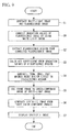
- FIG. 3 A flowchart illustrating image-processing in the image-processing unit 6 is shown in Fig. 3 .
- the white-light image information S1 is input to the white-light-image generating portion 61, thus generating the white-light image G1
- the fluorescence image information S2 is input to the fluorescence-image generating portion 62, thus generating the fluorescence image G2 (Step S1).
- the fluorescence image G2 is delivered to the extraction portion 63, and a fluorescence region F having gradation values equal to or higher than a prescribed threshold S is extracted (Step S2).
- Gradation values of respective positions of the extracted fluorescence region F are delivered to the coefficient-calculating portion 64 and position information of the fluorescence region F are delivered to the motion-effect generating portion 65.
- a mean m of gradation values of the fluorescence region F is calculated from gradation values delivered from the extraction portion 63, and a coefficient c is further calculated from the mean m (Step S3).
- a frame image Gf displaying a predetermined object O at the position of the fluorescence region F is generated based on the time t and the coefficient c (Step S4).
- the frame image Gf is added to a G-component image of the three component images that constitute the white-light image G1 (Step S5), a color synthetic image G is generated by use of the G-component image to which the frame image Gf has been added, as well as a raw R-component image and a raw B-component image (Step S6), and the generated synthetic image G is displayed on the display portion 7 (Step S7).
- the predetermined object O included in the synthetic image G produces a motion effect.
- an animation in which a predetermined green object O moves with a motion quantity depending on the gradation value of the fluorescence region F is displayed in a region corresponding to the fluorescence region F in the synthetic image G.
- the animation in which the predetermined object O moves is displayed at the position of the lesion within the synthetic image G on the display portion 7 that the observer is observing.
- the observer can easily recognize the lesion by the predetermined object O that is moving.
- the observer can intuitively and easily recognize fluorescence intensities, i.e., pathological severity in the lesion, based on the amplitude or speed of the motion of the predetermined object O.
- gradation values of three color-component images that constitute the white-light image G1 i.e. information on the morphology of the subject X, are included in the region of the synthetic image G where the object O is displayed. Therefore, even when the object O is displayed at the position of the lesion in the synthetic image G, the morphology of the lesion can be observed with sufficient clearness.
- the frame image Gf is added to the G-component image of the white-light image G1.
- the frame image Gf may be added to the R-component image or the B-component image.
- the frame image Gf may be divided and added to a plurality of component images. For example, gradation values of the frame image may be divided and added to the G-component image and the B-component image at a ratio of 2:1.
- the motion-effect generating portion 65 is assumed to impart a spatial motion effect to a region of the lesion within the synthetic image G.
- the aspect for the motion effect that the motion-effect generating portion 65 imparts to the region of the lesion is not limited thereto, and, as long as the motion effect is an effect causing a visual variation over time, such an effect is sufficient.
- the motion-effect generating portion 65 may generate a frame image that is assigned a gradation value that causes the color to vary over time within the region of the lesion, thus providing an effect causing the color to vary with a time period or with a range depending on the gradation values of the fluorescence region F.
- such an color variation effect may be combined with the above-described motion effect of the object O.
- the color variation refers to variation of hues, intensity, brightness or contrast of color.
- such a color variation effect may also be provided to allow the observer to easily recognize the lesion.
- the time period or range of the color variation can be set depending on the gradation values of the fluorescence region F to thereby allow the observer to intuitively and easily recognize the pathological severity of the lesion.
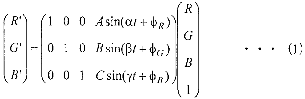
- the relation among the synthetic image G, the white-light image G1, and the frame image Gf in the region to which the color variation effect is imparted is defined by a matrix generally represented as formula (1).
- R', G', and B' are gradation values of the R-component, the G-component, and the B-component, respectively, of the synthetic image G.
- R, G, and B are gradation values of the R-component, the G-component, and the B-component, respectively, of the white-light image G1.
- Each component represented by sin is a gradation value of each color component of the frame image Gf.
- A, B and C are 0 or the coefficient c.
- a fluorescence observation apparatus 100 further includes a movement-quantity detecting portion 67 that detects a movement quantity of a subject X within a white-light image G1.
- the movement-quantity detecting portion 67 calculates a movement quantity Mv between a distal end 2a of an insertion portion 2 and the subject X by using well-known techniques such as, for example, by extracting a characteristic region from the white-light image G1 and calculating of a motion vector of the extracted characteristic region. Then, the movement-quantity detecting portion 67 outputs the calculated movement quantity Mv to a coefficient-calculating portion 64.
- the coefficient-calculating portion 64 calculates a coefficient c' based on the movement quantity Mv input from the movement-quantity detecting portion 67 and a mean m of gradation values of a fluorescence region F input from an extraction portion 63. For example, the coefficient-calculating portion 64 adds the movement quantity Mv to the above-described coefficient c to thereby calculate a coefficient c'.
- Step S8 the movement quantity Mv of the subject X within the white-light image G1 generated in Step S1 is detected from the white-light image G1 (Step S8).
- Step S3' the coefficient c' is calculated by also taking into consideration the detected movement quantity Mv.
- Step S4 the frame image Gf is generated by using the coefficient c' instead of using the coefficient c. Subsequent processing is identical to Fig. 3 , and therefore, descriptions thereof are omitted.
- the motion quantity of the object O varies depending on the movement quantity Mv.
- the motion quantity in a case where a viewing field of the white-light image G1 is moving is larger.
- a fluorescence observation apparatus 200 further includes a fluorescence-correcting portion 68 that corrects a fluorescence image G2 generated by a fluorescence-image generating portion 62 by use of a white-light image G1 generated by a white-light image-generating part 61.
- the fluorescence-correcting portion 68 divides gradation values of respective pixels of the fluorescence image G2 input from the fluorescence-image generating portion 62 by gradation values of respective pixels of the white-light image G1 input from the white-light-image generating portion 61 to thereby generate a corrected fluorescence image G2' in which gradation values are corrected, and outputs the generated corrected fluorescence image G2' to an extraction portion 63.
- the extraction portion 63 extracts a fluorescence region F from the corrected fluorescence image G2' instead of the fluorescence image G2.
- a gradation value of the fluorescence image G2 generated in Step S1 is corrected with a gradation value of the white-light image G1 (Step S9).
- Step S2' a fluorescence region F is extracted from the corrected fluorescence image G2' in which the gradation values have been corrected. Subsequent processing is identical to Fig. 3 , and therefore, descriptions thereof are omitted.
- the corrected fluorescence image G2' in which gradation values have been normalized by using the white-light image G1 is an image in which changes of gradation values depending on an observation distance and an observation angle between the distal end 2a of the insertion portion 2 and the subject X have been eliminated and in which original intensities of fluorescence emitted from each position of the subject X are more accurately reflected.
- the extraction portion 63 can extract the lesion as a fluorescence region F even more accurately by using such a corrected fluorescence image G2' instead of an unprocessed fluorescence image G2.
- the motion-effect generating portion 65 can provide the fluorescence region F with a motion quantity that still more-accurately represents the pathological severity of the lesion.
- a fluorescence observation apparatus 300 according to a third modification of this embodiment is one that is obtained by further modifying the second modification, and further includes a gradation-value-distribution calculating portion 69 that calculates the distribution of gradation values in the corrected fluorescence image G2' and a threshold-setting portion 70 that sets a threshold S in an extraction portion 63, as shown in Fig. 10 .
- the gradation-value-distribution calculating portion 69 calculate a mean M and a standard deviation ⁇ of gradation values of the corrected fluorescence image G2' based on the distribution of gradation values of the entirety of or a predetermined portion of the region of the corrected fluorescence image G2', and outputs the resulting mean M and standard deviation ⁇ to the threshold-setting portion 70 and a coefficient-calculating portion 64.
- the threshold-setting portion 70 calculates a threshold S from a sum of the mean M and the standard deviation ⁇ of gradation values. Then, the threshold-setting portion 70 sets the calculated threshold S as a prescribed threshold S for extracting the fluorescence region F in the extraction portion 63.
- the coefficient-calculating portion 64 uses m, M and ⁇ to calculate a coefficient c, for example, from the following formula (3).
- C m - M / ⁇
- Step S9 a mean M and a standard deviation ⁇ of gradation values of the corrected fluorescence image G2' are calculated (Step S10), and a threshold S that is used in the extraction portion 63 is set based on the values of M and ⁇ (Step S11).
- Step S11 a fluorescence region F having a gradation value equal to or higher than the threshold S set in Step S11 is extracted from the corrected fluorescence image G2'. Subsequent processing is identical to Fig. 3 , and therefore, descriptions thereof are omitted.
- the threshold S which is used in the extraction portion 63, and the coefficient c, which is used in the motion-effect generating portion 65, vary depending on the distribution of gradation values of the corrected fluorescence image G2'. Accordingly, even when there is a remaining variation of gradation values that depends on the observation distance and the observation angle, in the corrected fluorescence image G2', the lesion can always accurately be extracted. Additionally, even when there is variability among gradation values of respective pixels in the corrected fluorescence image G2', an even more highly accurate threshold S can be set. As a result, accuracy of extraction of the lesion can further be improved.
Landscapes
- Physics & Mathematics (AREA)
- Health & Medical Sciences (AREA)
- Life Sciences & Earth Sciences (AREA)
- Optics & Photonics (AREA)
- Surgery (AREA)
- Engineering & Computer Science (AREA)
- General Physics & Mathematics (AREA)
- General Health & Medical Sciences (AREA)
- Nuclear Medicine, Radiotherapy & Molecular Imaging (AREA)
- Pathology (AREA)
- Animal Behavior & Ethology (AREA)
- Veterinary Medicine (AREA)
- Public Health (AREA)
- Biophysics (AREA)
- Radiology & Medical Imaging (AREA)
- Molecular Biology (AREA)
- Medical Informatics (AREA)
- Biomedical Technology (AREA)
- Heart & Thoracic Surgery (AREA)
- Astronomy & Astrophysics (AREA)
- Chemical & Material Sciences (AREA)
- Analytical Chemistry (AREA)
- Signal Processing (AREA)
- Biochemistry (AREA)
- Immunology (AREA)
- Theoretical Computer Science (AREA)
- Endoscopes (AREA)
- Instruments For Viewing The Inside Of Hollow Bodies (AREA)
- Investigating, Analyzing Materials By Fluorescence Or Luminescence (AREA)
Abstract
Description
- The present invention relates to a fluorescence observation apparatus.
- In the related art, there have been known fluorescence observation apparatuses that acquire a reference image, such as a white-light image, capturing the morphology of a subject, and a fluorescence image visualizing a lesion by capturing fluorescence from the subject, and that display the lesion within the fluorescence image with the lesion superimposed on the reference image (for example, see
Patent Literatures 1 and 2) . -
- {PTL 1} the Publication of Japanese Patent No.
4533673 - {PTL 2} Japanese Unexamined Patent Application, Publication No.
2005-204958 - In
Patent Literature 1, the fluorescence image is added to any of a red-component image, a green-component image, and a blue-component image constituting the color reference image to thereby display the lesion as a red, green, or blue region on the reference image. In this case, since the reference image includes information on original gradation values, i.e. information on the morphology of the subject, in a region displaying the lesion, there is an advantage that the morphology of the lesion can also be observed. However, there is a disadvantage that it is difficult to obtain sufficient visibility of the lesion. On the other hand, inPatent Literature 2, the region of the lesion in the reference image is filled with a false color. In this case, although there is an advantage that the visibility of the lesion will be improved, there is a disadvantage that observation of the morphology of the lesion within the reference image is impeded by the false color. - The present invention was conceived in view of the above-described circumstances, and an object thereof is to provide a fluorescence observation apparatus that can display a lesion on a reference image with excellent visibility without impeding observation of the lesion using the reference image.
- In order to achieve the above-described object, the present invention provides the following solutions.
- The present invention provides a fluorescence observation apparatus including: a light source that irradiates a subject with reference light and excitation light; a fluorescence-image generating portion that captures fluorescence produced in the subject due to irradiation with the excitation light from the light source to generate a fluorescence image; a reference-image generating portion that captures return light returning from the subject due to irradiation with the reference light from the light source to generate a color reference image; an extraction portion that extracts, from the fluorescence image generated by the fluorescence-image generating portion, a fluorescence region having a gradation value equal to or higher than a prescribed threshold; a motion-effect generating portion that generates a frame image that is assigned a time-varying gradation value so as to bring about an effect that is visually time-varying with a variation quantity depending on a gradation value of the fluorescence region, in a region corresponding to the fluorescence region extracted by the extraction portion; and a synthesis portion that adds the frame image generated by the motion-effect generating portion to at least one of a plurality of color-component images constituting the reference image, to synthesize a synthetic image from the plurality of color-component images including the color-component image that the frame image has been added to.
- According to the present invention, the reference image in which the morphology of the subject is captured by irradiating the subject with reference light from the light source is acquired by the reference-image generating portion. Meanwhile, the fluorescence image in which fluorescence from a lesion present in the subject is captured with irradiation of excitation light from the light source is acquired by the fluorescence-image generating portion. The lesion within the fluorescence image is extracted as a fluorescence region by the extraction portion. Subsequently, the frame image having a gradation value is generated, by a motion-effect generating portion, in the region within the reference image corresponding to the extracted lesion. Then, the frame image is added to a color-component image constituting the reference image by a synthesis portion, to thereby synthesize the synthetic image displaying the lesion on the reference image.
- In this case, in the lesion within continuously-displayed synthetic images, a motion effect is caused by time-dependent variation of the gradation value with a variation quantity set depending on an intensity of fluorescence from the lesion. Therefore, the lesion can be displayed on the reference image with excellent visibility. In addition, the synthetic image includes information on gradation values possessed by color-component images constituting the reference image, i.e., information on the morphology of the subject, within the region of lesion. Therefore, observation of the lesion using the reference image can also be carried out.
- In the above-described invention, a coefficient-calculating portion that calculates a coefficient, which increases with an increase of the gradation value of the fluorescence region, based on said gradation value may be provided, and the motion-effect generating portion may determine the variation quantity based on the coefficient calculated by the coefficient-calculating portion.
- This allows appropriate adjustment of the variation quantity for the motion effect in the lesion by use of the coefficient that has appropriately been set by the coefficient-calculating portion. Accordingly, even when the gradation value of the fluorescence region is small, a sufficiently-large motion effect can be imparted to the lesion, thereby allowing an observer to even more reliably recognize the lesion.
- In the above-described invention, the motion-effect generating portion may generate the frame image that brings about an effect causing the predetermined object to move within the corresponding region at a speed depending on the gradation value of the fluorescence region.
- This provides an effect causing a predetermined object to move in the lesion within the synthetic image. The observer can intuitively and easily recognize the pathological severity of the lesion from the speed of movement of the object.
- In the above-described invention, the motion-effect generating portion may generate the frame image that brings about an effect causing a predetermined object to move within the corresponding region with an amplitude depending on the gradation value of the fluorescence region.
- This provides an effect causing the predetermined object to move in the lesion within the synthetic image. The observer can intuitively and easily recognize the pathological severity of the lesion from the amplitude of movement of the object.
- In the above-described invention, the motion-effect generating portion may generate the frame image that brings about an effect causing a color to vary with a period depending on the gradation value of the fluorescence region.
- This brings about an effect causing a color to vary in the lesion within the synthetic image. The observer can intuitively and easily recognize the pathological severity of the lesion from the time period of the color variation.
- In the above-described invention, the motion-effect generating portion may generate the frame image that brings about an effect causing a color to vary with a range depending on the gradation value of the fluorescence region.
- This brings about an effect causing a color to vary in the lesion within the synthetic image. The observer can intuitively and easily recognize the pathological severity of the lesion from the range of color variation.
- In the above-described configuration displaying an object in the synthetic image, a movement-quantity detecting portion that detects a movement quantity of the subject in the reference image may be provided, and the motion-effect generating portion may provide a variation effect with a variation quantity depending on a value obtained by adding the movement quantity of the subject detected by the movement-quantity detecting portion to the gradation value of the fluorescence region.
- This allows the magnitude of the motion of the object in the lesion to vary against the motion of the subject when the subject is moving within the reference image because of movement of the field of view. Accordingly, the motion of the object can sufficiently be accentuated against the moving subject.
- In the above-described invention, a fluorescence-correcting portion that divides the fluorescence image generated by the fluorescence-image generating portion by the reference image generated by the reference-image generating portion to thereby correct the gradation value of the fluorescence image may be provided, and the extraction portion may extract the fluorescence region from the fluorescence image corrected by the fluorescence-correcting portion.
- This eliminates changes of gradation values within the fluorescence image depending on an observation distance and an observation angle, thereby obtaining a fluorescence image that has been corrected so as to more accurately reflect original intensities of fluorescence caused in the subject. By use of such a corrected fluorescence image, the lesion can more accurately be extracted. Furthermore, a motion effect of more accurately representing the pathological severity of the lesion can be imparted to the lesion.
- In the above-described configuration including the fluorescence-correcting portion, a threshold-setting portion that sets the prescribed threshold in the extraction portion based on a sum of a mean of gradation values of respective pixels in the fluorescence image corrected by the fluorescence-correcting portion and a standard deviation of the gradation values may be provided.
- This makes it possible to update the threshold in the extraction portion to follow variations of gradation values of respective pixels in the fluorescence image. Furthermore, even when there is variability among the gradation values of respective pixels, a highly precise threshold can be set.
- The present invention affords the advantage that it is possible to display a lesion on a reference image with excellent visibility without impeding observation of the lesion using the reference image.
-
- {
Fig. 1 }
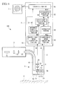
Fig. 1 is a diagram showing the overall configuration of a fluorescence observation apparatus according to one embodiment of the present invention. - {
Fig. 2 }
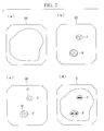
Fig. 2 shows (a) a white-light image, (b) a fluorescence image, (c) a frame image, and (d) a synthetic image that are generated in an image-processing unit of the fluorescence observation apparatus inFig. 1 . - {
Fig. 3 }
Fig. 3 is a flowchart illustrating processing in the image-processing unit inFig. 1 . - {
Fig. 4 }
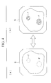
Fig. 4 is a modification of a synthetic image generated in the image-processing unit of the fluorescence observation apparatus inFig. 1 , and shows (a) a case where the gradation value is minimum and (b) a case where the gradation value is maximum. - {
Fig. 5 }
Fig. 5 is a modification of a synthetic image generated in the image-processing unit of the fluorescence observation apparatus inFig. 1 , and shows (a) a case where the hue is red, (b) a case where the hue is green, and (c) a case where the hue is blue. - {
Fig. 6 }
Fig. 6 is an overall configuration diagram of a first modification of the fluorescence observation apparatus inFig. 1 . - {
Fig. 7 }
Fig. 7 is a flowchart illustrating processing in the image-processing unit inFig. 6 . - {
Fig. 8 }
Fig. 8 is an overall configuration diagram of a second modification of the fluorescence observation apparatus inFig. 1 . - {
Fig. 9 }
Fig. 9 is a flowchart illustrating processing in the image-processing unit inFig. 8 . - {
Fig. 10 }
Fig. 10 is an overall configuration diagram of a third modification of the fluorescence observation apparatus inFig. 1 . - {
Fig. 11 }
Fig. 11 is a flowchart illustrating processing in the image-processing unit inFig. 10 . - A
fluorescence observation apparatus 1 according to one embodiment of the present invention will be described below with reference toFigs. 1 to 5 . - The
fluorescence observation apparatus 1 according to this embodiment is an endoscopic apparatus. As shown inFig. 1 , thefluorescence observation apparatus 1 includes anelongated insertion portion 2 that is inserted into a body; alight source 3; anillumination unit 4 that radiates excitation light and white light (reference light) from thelight source 3 from adistal end 2a of theinsertion portion 2 toward a subject X; an image-acquisition unit 5 that is provided in thedistal end 2a of theinsertion portion 2 and that acquires image information S1 and S2 of the subject X; an image-processing unit 6 that is disposed at the base end of theinsertion portion 2 and that processes the image information S1 and S2 acquired by the image-acquisition unit 5; and adisplay portion 7 that displays an image G which has been processed by the image-processing unit 6. - The
light source 3 includes axenon lamp 31; afilter 32 that extracts excitation light and white light from the light emitted from thexenon lamp 31; and acoupling lens 33 that focuses the excitation light and the white light extracted by thefilter 32. Thefilter 32 selectively transmits light with a wavelength band of 400 nm to 740 nm corresponding to the excitation light and white light. In other words, near-infrared light (e.g. a wavelength band of 700 nm to 740 nm) is used as the excitation light in this embodiment. - The
illumination unit 4 includes alight guide fiber 41 that is disposed along almost the entire length in the longitudinal direction of theinsertion portion 2 and an illuminationoptical system 42 that is provided at thedistal end 2a of theinsertion portion 2. Thelight guide fiber 41 guides the excitation light and the white light focused by thecoupling lens 33. The illuminationoptical system 42 spreads out the excitation light and the white light that have been guided by thelight guide fiber 41, and radiates them onto the subject X that faces thedistal end 2a of theinsertion portion 2. - The image-
acquisition unit 5 includes anobjective lens 51 that collects light from the subject X; adichroic mirror 52 that reflects excitation light and fluorescence among the light collected by theobjective lens 51 and that transmits white light (with a wavelength band of 400 nm to 700 nm; return light) having a wavelength shorter than that of the excitation light; two focusinglenses dichroic mirror 52 and the white light transmitted through thedichroic mirror 52; an image-acquisition device 55, such as a color CCD, that captures the white light focused by the focusinglens 54; and an image-acquisition device 56, such as a highly sensitive monochrome CCD, that captures the fluorescence focused by the focusinglens 53. In the figure,reference sign 57 refers to an excitation-light cutting filter that selectively transmits fluorescence (e.g., a wavelength band of 760 nm to 850 nm) among the light reflected by thedichroic mirror 52 and that blocks excitation light. - Based on the combination of the
filter 32, thedichroic mirror 52, and the excitation-light cutting filter 67 having such wavelength characteristics, a white-light image G1 and a fluorescence image G2 can simultaneously be acquired, for example, by administering an anti-CEA antibody labeled with a fluorescent dye Cy7 to the subject X, followed by observation. CEA is a protein that is expressed specifically in cancer. - The image-
processing unit 6 includes a white-light-image generating portion (reference-image generating portion) 61 that generates a white-light image (reference image) G1 from white-light image information S1 acquired by the image-acquisition device 55; a fluorescence-image generating portion 62 that generates a fluorescence image G2 from fluorescence image information S2 acquired by the image-acquisition device 56; anextraction portion 63 that extracts a fluorescence region F from the fluorescence image G2 generated by the fluorescence-image generating portion 62; a coefficient-calculatingportion 64 that calculates a coefficient c for generation of a frame image Gf described below by use of a gradation value of the fluorescence region F extracted by theextraction portion 63; a motion-effect generating portion 65 that generates a frame image Gf time-varying at the position of the fluorescence region F; and asynthesis portion 66 that adds the frame image Gf generated by the motion-effect generating portion 65 to the white-light image G1 to generate a synthetic image G.Fig. 2(a)-(d) show different types of images G1, G2, Gf, and G that are generated in image-processing in the image-processing unit 6. - The
extraction portion 63 compares the gradation value of each pixel of the fluorescence image G2 input from the fluorescence-image generating portion 62 with a prescribed threshold S, and extracts pixels having a gradation value equal to or higher than the prescribed threshold S as a fluorescence region F, as shown in (b) ofFig. 2 . Theextraction portion 63 outputs gradation values of the extracted pixels to the coefficient-calculatingportion 64 and outputs positions of the extracted pixels to the motion-effect generating portion 65. - The coefficient-calculating
portion 64 calculates a mean m of gradation values of pixels, constituting the fluorescence region F, that have been input by theextraction portion 63, calculates a coefficient c based on the calculated mean m, and outputs the calculated coefficient c to the motion-effect generating portion 65. The coefficient c is set as a function that increases with an increase of the mean m, for example, a function proportional to the mean m. - The coefficient-calculating
portion 64 may calculate the coefficient c by use of a median or mode of gradation values of pixels extracted by theextraction portion 63, instead of using the mean m. - The motion-
effect generating portion 65 has a clock that counts time t. The motion-effect generating portion 65 generates the frame image Gf constituting an animation that moves with a motion quantity (variation quantity) based on the coefficient c as time t passes, depending on the time t counted by the clock. - Specifically, the motion-
effect generating portion 65 generates the frame image Gf displaying a predetermined object 0 within a region corresponding to the fluorescence region F, as shown in (c) ofFig. 2 , based on positions of pixels input by theextraction portion 63. In other words, the frame image Gf has a gradation value in pixels that constitute the object O. The gradation value may be any prescribed value, or may be a value set based on the gradation value of the fluorescence region F. - In (c) of
Fig. 2 , as one example of the predetermined object O, a plurality of circles that have a certain dimension and that are arranged at a regular interval are shown. The motion-effect generating portion 65 creates a frame image Gf generating an animation in which the circles move within the fluorescence region F over time t when the frame image Gf is continuously displayed. - The motion quantity means the amplitude and speed of motion of the object O, and is set as a function that increases with an increase of the coefficient c, for example, a function proportional to the coefficient c. As the coefficient c becomes larger, i.e. as the gradation value of the fluorescence region F becomes larger, the motion-
effect generating portion 65 generates a frame image Gf to make at least one of the amplitude and the speed of the motion of the object O larger. - The
synthesis portion 66 adds the frame image Gf input from the motion-effect generating portion 65 to any of a red (R)-component image, a green (G)-component image, and a blue (B)-component image, for example, to the G-component image, that constitute the white-light image G1 input from the white-light-image generating portion 61. Specifically, thesynthesis portion 66 adds gradation values of respective pixels of the frame image Gf to gradation values of respective pixels of the G-component image. Then, the synthetic image G is synthesized from the G-component image to which the frame image Gf has been added, as well as the other two, that is, the R-component image and the B-component image, and the generated synthetic image G is output to thedisplay portion 7. - Next, the operation of the
fluorescence observation apparatus 1 configured in such a manner will be described. In order to observe biological tissue inside the body, which is the subject X, by using thefluorescence observation apparatus 1 according to this embodiment, a fluorescence substance that accumulates in the lesion is preliminarily administered to the subject X. Then, theinsertion portion 2 is inserted into the body so that itsdistal end 2a is disposed facing the subject X, and excitation light and white light are radiated from thedistal end 2a of theinsertion portion 2 to the subject X by operation of thelight source 3. - In the subject X, the fluorescent substance included in the lesion is excited by the excitation light, thereby emitting fluorescence therefrom, and white light is reflected at the surface of the subject X. Portions of the fluorescence emitted from the subject X and the reflected white light return to the
distal end 2a of theinsertion portion 2, and are collected by theobjective lens 51. - White light among the light collected by the
objective lens 51 passes through thedichroic mirror 52, is focused by the focusinglens 54, and is acquired as white-light image information S1 by the image-acquisition device 55. Meanwhile, the fluorescence collected by theobjective lens 51 is reflected by thedichroic mirror 52, and excitation light is removed therefrom by the excitation-light cutting filter 57. Then, the fluorescence is focused by the focusinglens 53 and is acquired as fluorescence image information S2 by the image-acquisition device 56. Image information S1 and S2 acquired by the respective image-acquisition devices processing unit 6. - A flowchart illustrating image-processing in the image-
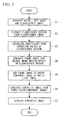
processing unit 6 is shown inFig. 3 . - In the image-
processing unit 6, the white-light image information S1 is input to the white-light-image generating portion 61, thus generating the white-light image G1, and the fluorescence image information S2 is input to the fluorescence-image generating portion 62, thus generating the fluorescence image G2 (Step S1). - The fluorescence image G2 is delivered to the
extraction portion 63, and a fluorescence region F having gradation values equal to or higher than a prescribed threshold S is extracted (Step S2). Gradation values of respective positions of the extracted fluorescence region F are delivered to the coefficient-calculatingportion 64 and position information of the fluorescence region F are delivered to the motion-effect generating portion 65. Then, in the coefficient-calculatingportion 64, a mean m of gradation values of the fluorescence region F is calculated from gradation values delivered from theextraction portion 63, and a coefficient c is further calculated from the mean m (Step S3). - Then, in the motion-
effect generating portion 65, a frame image Gf displaying a predetermined object O at the position of the fluorescence region F is generated based on the time t and the coefficient c (Step S4). Then, in thesynthesis portion 66, the frame image Gf is added to a G-component image of the three component images that constitute the white-light image G1 (Step S5), a color synthetic image G is generated by use of the G-component image to which the frame image Gf has been added, as well as a raw R-component image and a raw B-component image (Step S6), and the generated synthetic image G is displayed on the display portion 7 (Step S7). - In the synthetic image G continuously displayed on the
display portion 7, the predetermined object O included in the synthetic image G produces a motion effect. In other words, an animation in which a predetermined green object O moves with a motion quantity depending on the gradation value of the fluorescence region F is displayed in a region corresponding to the fluorescence region F in the synthetic image G. - Thus, according to this embodiment, the animation in which the predetermined object O moves is displayed at the position of the lesion within the synthetic image G on the
display portion 7 that the observer is observing. The observer can easily recognize the lesion by the predetermined object O that is moving. Furthermore, the observer can intuitively and easily recognize fluorescence intensities, i.e., pathological severity in the lesion, based on the amplitude or speed of the motion of the predetermined object O. Additionally, gradation values of three color-component images that constitute the white-light image G1, i.e. information on the morphology of the subject X, are included in the region of the synthetic image G where the object O is displayed. Therefore, even when the object O is displayed at the position of the lesion in the synthetic image G, the morphology of the lesion can be observed with sufficient clearness. - In this embodiment, it is assumed that the frame image Gf is added to the G-component image of the white-light image G1. However, instead of this, the frame image Gf may be added to the R-component image or the B-component image. Alternatively, the frame image Gf may be divided and added to a plurality of component images. For example, gradation values of the frame image may be divided and added to the G-component image and the B-component image at a ratio of 2:1.
- In this embodiment, the motion-
effect generating portion 65 is assumed to impart a spatial motion effect to a region of the lesion within the synthetic image G. However, the aspect for the motion effect that the motion-effect generating portion 65 imparts to the region of the lesion is not limited thereto, and, as long as the motion effect is an effect causing a visual variation over time, such an effect is sufficient. For example, the motion-effect generating portion 65 may generate a frame image that is assigned a gradation value that causes the color to vary over time within the region of the lesion, thus providing an effect causing the color to vary with a time period or with a range depending on the gradation values of the fluorescence region F. Additionally, such an color variation effect may be combined with the above-described motion effect of the object O. In this case, the color variation refers to variation of hues, intensity, brightness or contrast of color. - Thus, as an alternative to or besides spatial motion, such a color variation effect may also be provided to allow the observer to easily recognize the lesion. Additionally, the time period or range of the color variation can be set depending on the gradation values of the fluorescence region F to thereby allow the observer to intuitively and easily recognize the pathological severity of the lesion.
- In this case, the relation among the synthetic image G, the white-light image G1, and the frame image Gf in the region to which the color variation effect is imparted is defined by a matrix generally represented as formula (1). In formula (1), R', G', and B' are gradation values of the R-component, the G-component, and the B-component, respectively, of the synthetic image G. R, G, and B are gradation values of the R-component, the G-component, and the B-component, respectively, of the white-light image G1. Each component represented by sin is a gradation value of each color component of the frame image Gf. A, B and C are 0 or the coefficient c.
- {Math. 1}
- Speaking of cases where a color-contrast variation effect is provided, when letting ΦR=ΦG=ΦB=0, all gradation values of the R-component, the G-component, and the B-component vary in the same phase in the frame image Gf. Further, when letting A=C=0, B=c and β=1, a gradation value of the G-component of the frame image Gf that periodically varies with a range proportional to the coefficient c is added to a gradation value of the G-component image. Accordingly, as shown in (a) and (b) of
Fig. 4 , the fluorescence region F blinks between a transparent color and a dark green in the synthetic image G. On the other hand, when letting A=C=0, B=1 and β=c, the gradation value of the G-component of the frame image Gf that periodically varies with a speed proportional to the coefficient c is added to the G-component image. Accordingly, the fluorescence region F blinks in the synthetic image G. In contrast, when letting A=-1, B=1, C=0 and α=β=1, the gradation value of the R-component and the gradation value of the G component of the frame image Gf that vary in phases opposite to one another are added to the R-component image and the G-component image, respectively, of the white-light image G1. In this case, when the gradation value of the G-component is maximum in the synthetic image G, the gradation value of the R-component is minimum, and the hue of the fluorescence region F varies alternately between red and green. - Speaking of cases where a hue variation effect is provided, when values that are different from each other are assigned to ϕR, ϕG and ϕB, gradation values of the R component, the G component, and the B component vary with different phases from one another in the frame image Gf. For example, when letting ϕR=0, ϕG=2π/3, and ϕB=4π/3, as well as A=B=C=1 and α=β=γ=c, as shown in (a) to (c) of
Fig. 5 , the hue of the fluorescence region F in the synthetic image G varies in the order red, green and blue with a time period proportional to the coefficient c. On the other hand, when letting A=B=C=c and α=β=γ=1, the hue of the fluorescence region F in the synthetic image G varies with a range proportional to the coefficient c. In (a) to (c) ofFig. 5 , differences in the hatching directions represent differences in the hue. - Next, modifications of the above-described
fluorescence observation apparatus 1 according to this embodiment will be described. - As shown in
Fig. 6 , afluorescence observation apparatus 100 according to a first modification of this embodiment further includes a movement-quantity detecting portion 67 that detects a movement quantity of a subject X within a white-light image G1. - The movement-quantity detecting portion 67 calculates a movement quantity Mv between a
distal end 2a of aninsertion portion 2 and the subject X by using well-known techniques such as, for example, by extracting a characteristic region from the white-light image G1 and calculating of a motion vector of the extracted characteristic region. Then, the movement-quantity detecting portion 67 outputs the calculated movement quantity Mv to a coefficient-calculatingportion 64. - The coefficient-calculating
portion 64 calculates a coefficient c' based on the movement quantity Mv input from the movement-quantity detecting portion 67 and a mean m of gradation values of a fluorescence region F input from anextraction portion 63. For example, the coefficient-calculatingportion 64 adds the movement quantity Mv to the above-described coefficient c to thereby calculate a coefficient c'. - The operation of the
fluorescence observation apparatus 100 configured in such a manner will be described with reference toFig. 7 . - In the this modification, the movement quantity Mv of the subject X within the white-light image G1 generated in Step S1 is detected from the white-light image G1 (Step S8). In next Step S3', the coefficient c' is calculated by also taking into consideration the detected movement quantity Mv. In Step S4, the frame image Gf is generated by using the coefficient c' instead of using the coefficient c. Subsequent processing is identical to
Fig. 3 , and therefore, descriptions thereof are omitted. - Thus, according to this modification, when the subject X is moved within the white-light image G1 based on relative movement of the
distal end 2a of theinsertion portion 2 and the subject X, the motion quantity of the object O varies depending on the movement quantity Mv. In other words, relative to a motion quantity in a case where the viewing field of the white-light image G1 is constant, the motion quantity in a case where a viewing field of the white-light image G1 is moving is larger. In such a way, by varying the motion quantity of the object O relative to the motion quantity of the subject X, motion of the object O is sufficiently accentuated against the moving subject X, thereby allowing the observer to reliably recognize the lesion. - As shown in
Fig. 8 , afluorescence observation apparatus 200 according to the second modification of this embodiment further includes a fluorescence-correctingportion 68 that corrects a fluorescence image G2 generated by a fluorescence-image generating portion 62 by use of a white-light image G1 generated by a white-light image-generatingpart 61. The fluorescence-correctingportion 68 divides gradation values of respective pixels of the fluorescence image G2 input from the fluorescence-image generating portion 62 by gradation values of respective pixels of the white-light image G1 input from the white-light-image generating portion 61 to thereby generate a corrected fluorescence image G2' in which gradation values are corrected, and outputs the generated corrected fluorescence image G2' to anextraction portion 63. - The
extraction portion 63 extracts a fluorescence region F from the corrected fluorescence image G2' instead of the fluorescence image G2. - The operation of the
fluorescence observation apparatus 200 configured in such a manner will be described with reference toFig. 9 . - In the present modification, a gradation value of the fluorescence image G2 generated in Step S1 is corrected with a gradation value of the white-light image G1 (Step S9). In the subsequent Step S2', a fluorescence region F is extracted from the corrected fluorescence image G2' in which the gradation values have been corrected. Subsequent processing is identical to
Fig. 3 , and therefore, descriptions thereof are omitted. - Thus, according to the present modification, the corrected fluorescence image G2' in which gradation values have been normalized by using the white-light image G1 is an image in which changes of gradation values depending on an observation distance and an observation angle between the
distal end 2a of theinsertion portion 2 and the subject X have been eliminated and in which original intensities of fluorescence emitted from each position of the subject X are more accurately reflected. Theextraction portion 63 can extract the lesion as a fluorescence region F even more accurately by using such a corrected fluorescence image G2' instead of an unprocessed fluorescence image G2. Additionally, the motion-effect generating portion 65 can provide the fluorescence region F with a motion quantity that still more-accurately represents the pathological severity of the lesion. - A
fluorescence observation apparatus 300 according to a third modification of this embodiment is one that is obtained by further modifying the second modification, and further includes a gradation-value-distribution calculating portion 69 that calculates the distribution of gradation values in the corrected fluorescence image G2' and a threshold-settingportion 70 that sets a threshold S in anextraction portion 63, as shown inFig. 10 . - The gradation-value-
distribution calculating portion 69 calculate a mean M and a standard deviation σ of gradation values of the corrected fluorescence image G2' based on the distribution of gradation values of the entirety of or a predetermined portion of the region of the corrected fluorescence image G2', and outputs the resulting mean M and standard deviation σ to the threshold-settingportion 70 and a coefficient-calculatingportion 64. - For example, as shown in the following formula (2), the threshold-setting
portion 70 calculates a threshold S from a sum of the mean M and the standard deviation σ of gradation values. Then, the threshold-settingportion 70 sets the calculated threshold S as a prescribed threshold S for extracting the fluorescence region F in theextraction portion 63. Here, a and b are coefficients that are set so as to decrease with an increase in the proportion of a region of a predetermined gradation value or higher occupying the corrected fluorescence image G2'.
- The coefficient-calculating
portion 64 uses m, M and σ to calculate a coefficient c, for example, from the following formula (3).
- The operation of the
fluorescence observation apparatus 300 configured in such a manner will be described with reference toFig. 11 . - In the present modification, after the corrected fluorescence image G2' is generated in Step S9, a mean M and a standard deviation σ of gradation values of the corrected fluorescence image G2' are calculated (Step S10), and a threshold S that is used in the
extraction portion 63 is set based on the values of M and σ (Step S11). In subsequent Step S2', a fluorescence region F having a gradation value equal to or higher than the threshold S set in Step S11 is extracted from the corrected fluorescence image G2'. Subsequent processing is identical toFig. 3 , and therefore, descriptions thereof are omitted. - Thus, according to the present modification, the threshold S, which is used in the
extraction portion 63, and the coefficient c, which is used in the motion-effect generating portion 65, vary depending on the distribution of gradation values of the corrected fluorescence image G2'. Accordingly, even when there is a remaining variation of gradation values that depends on the observation distance and the observation angle, in the corrected fluorescence image G2', the lesion can always accurately be extracted. Additionally, even when there is variability among gradation values of respective pixels in the corrected fluorescence image G2', an even more highly accurate threshold S can be set. As a result, accuracy of extraction of the lesion can further be improved. -
- 1, 100, 200, 300
- Fluorescence observation apparatus
- 2
- Insertion portion
- 3
- Light source
- 31
- Xenon lamp
- 32
- Filter
- 33
- Coupling lens
- 4
- Illumination unit
- 41
- Light guide fiber
- 42
- Illumination optical system
- 5
- Image-acquisition unit
- 51
- Objective lens
- 52
- Dichroic mirror
- 53, 54
- Focusing lens
- 55, 56
- Image-acquisition device
- 57
- Excitation-light cutting filter
- 6
- Image-processing unit
- 61
- White-light-image generating portion (reference-image generating portion)
- 62
- Fluorescence-image generating portion
- 63
- Extraction portion
- 64
- Coefficient-calculating portion
- 65
- Motion-effect generating portion
- 66
- Synthesis portion
- 67
- Movement-quantity detecting portion
- 68
- Fluorescence-correcting portion
- 69
- Gradation-value-distribution calculating portion
- 70
- Threshold-setting portion
- 7
- Display portion
- G
- Synthetic image
- G1
- White-light image (reference image)
- G2
- Fluorescence image
- G2'
- Corrected fluorescence image
- Gf
- Frame image
Claims (9)
- A fluorescence observation apparatus, comprising:a light source that irradiates a subject with reference light and excitation light;a fluorescence-image generating portion that captures fluorescence produced in the subject due to irradiation with the excitation light from the light source to generate a fluorescence image;a reference-image generating portion that captures return light returning from the subject due to irradiation with the reference light from the light source to generate a color reference image;an extraction portion that extracts, from the fluorescence image generated by the fluorescence-image generating portion, a fluorescence region having a gradation value equal to or higher than a prescribed threshold;a motion-effect generating portion that generates a frame image that is assigned a time-varying gradation value so as to bring about an effect that is visually time-varying with a variation quantity depending on a gradation value of the fluorescence region, in a region corresponding to the fluorescence region extracted by the extraction portion; anda synthesis portion that adds the frame image generated by the motion-effect generating portion to at least one of a plurality of color-component images constituting the reference image, to synthesize a synthetic image from the plurality of color-component images comprising the color-component image that the frame image has been added to.
- The fluorescence observation apparatus according to claim 1, further comprising a coefficient-calculating portion that calculates a coefficient, which increases with an increase of the gradation value of the fluorescence region, based on said gradation value, wherein the motion-effect generating portion determines the variation quantity based on the coefficient calculated by the coefficient-calculating portion.
- The fluorescence observation apparatus according to claim 1 or 2, wherein the motion-effect generating portion generates the frame image that brings about an effect causing a predetermined object to move within the corresponding region at a speed depending on the gradation value of the fluorescence region.
- The fluorescence observation apparatus according to any one of claims 1 to 3, wherein the motion-effect generating portion generates the frame image that brings about an effect causing a predetermined object to move within the corresponding region with an amplitude depending on the gradation value of the fluorescence region.
- The fluorescence observation apparatus according to any one of claims 1 to 4, wherein the motion-effect generating portion generates the frame image that brings about an effect causing a color to vary with a period depending on the gradation value of the fluorescence region.
- The fluorescence observation apparatus according to any one of claims 1 to 5, wherein the motion-effect generating portion generates the frame image that brings about an effect causing a color to vary with a range depending on the gradation value of the fluorescence region.
- The fluorescence observation apparatus according to claim 3 or 4, further comprising a movement-quantity detecting portion that detects a movement quantity of the subject in the reference image, wherein the motion-effect generating portion generates the frame image that varies with a variation quantity depending on a value obtained by adding the movement quantity of the subject detected by the movement-quantity detecting portion to the gradation value of the fluorescence region.
- The fluorescence observation apparatus according to any one of claims 1 to 7, further comprising a fluorescence-correcting portion that divides the fluorescence image generated by the fluorescence-image generating portion by the reference image generated by the reference-image generating portion to thereby correct the gradation value of the fluorescence image, wherein the extraction portion extracts the fluorescence region from the fluorescence image corrected by the fluorescence-correcting portion.
- The fluorescence observation apparatus according to claim 8, further comprising a threshold-setting portion that sets the prescribed threshold in the extraction portion based on a sum of a mean of gradation values of respective pixels in the fluorescence image corrected by the fluorescence-correcting portion and a standard deviation of the gradation values.
Applications Claiming Priority (2)
| Application Number | Priority Date | Filing Date | Title |
|---|---|---|---|
| JP2012272305 | 2012-12-13 | ||
| PCT/JP2013/082437 WO2014091964A1 (en) | 2012-12-13 | 2013-12-03 | Fluorescent observation device |
Publications (2)
| Publication Number | Publication Date |
|---|---|
| EP2932882A1 true EP2932882A1 (en) | 2015-10-21 |
| EP2932882A4 EP2932882A4 (en) | 2017-01-11 |
Family
ID=50934256
Family Applications (1)
| Application Number | Title | Priority Date | Filing Date |
|---|---|---|---|
| EP13863259.1A Withdrawn EP2932882A4 (en) | 2012-12-13 | 2013-12-03 | Fluorescent observation device |
Country Status (5)
| Country | Link |
|---|---|
| US (1) | US9207179B2 (en) |
| EP (1) | EP2932882A4 (en) |
| JP (1) | JP6188721B2 (en) |
| CN (1) | CN104853666B (en) |
| WO (1) | WO2014091964A1 (en) |
Cited By (3)
| Publication number | Priority date | Publication date | Assignee | Title |
|---|---|---|---|---|
| CN110381806A (en) * | 2017-03-31 | 2019-10-25 | Hoya株式会社 | Electronic endoscope system |
| EP3616596A3 (en) * | 2016-05-23 | 2020-03-18 | Leica Instruments (Singapore) Pte. Ltd. | Image processor, medical observation device, such as a microscope or an endoscope, and method using pseudo-color image data |
| EP3733042A1 (en) * | 2019-05-01 | 2020-11-04 | Karl Storz Imaging, Inc. | Video display system having an adaptive overlay |
Families Citing this family (17)
| Publication number | Priority date | Publication date | Assignee | Title |
|---|---|---|---|---|
| CN104515760B (en) * | 2014-12-17 | 2017-10-31 | 深圳市纳观生物有限公司 | Two Colour Fluorescence positions super-resolution biology microscope method and system |
| WO2016203572A1 (en) * | 2015-06-17 | 2016-12-22 | オリンパス株式会社 | Imaging apparatus |
| WO2017175452A1 (en) * | 2016-04-04 | 2017-10-12 | ソニー株式会社 | Image processing device, image pickup device, image processing method, and program |
| KR101998592B1 (en) * | 2017-09-20 | 2019-07-10 | 인더스마트 주식회사 | Apparatus and method for detecting near-infrared fluorescence |
| CN108195802B (en) * | 2017-11-21 | 2020-09-15 | 广州标旗电子科技有限公司 | Diamond luminescence imaging detection method |
| JP7134759B2 (en) * | 2018-07-13 | 2022-09-12 | ソニー・オリンパスメディカルソリューションズ株式会社 | Medical image processing device and medical observation system |
| JP7337073B2 (en) * | 2018-08-17 | 2023-09-01 | 富士フイルム株式会社 | MEDICAL IMAGE PROCESSING APPARATUS, ENDOSCOPE SYSTEM, AND METHOD OF OPERATION OF MEDICAL IMAGE PROCESSING APPARATUS |
| WO2020054542A1 (en) * | 2018-09-11 | 2020-03-19 | 富士フイルム株式会社 | Medical image processing device, medical image processing method and program, and endoscope system |
| EP4285809B1 (en) * | 2018-09-28 | 2025-09-03 | FUJIFILM Corporation | Medical image processing device, medical image processing method, program, diagnosis assistance device, and endoscope system |
| JP7038641B2 (en) * | 2018-11-02 | 2022-03-18 | 富士フイルム株式会社 | Medical diagnosis support device, endoscopic system, and operation method |
| EP3690819B1 (en) * | 2019-01-31 | 2023-09-13 | Leica Instruments (Singapore) Pte. Ltd. | Image processing device and method, and medical observation device comprising such an image processing device, using an intensity or brightness-dependent variation of a pseudocolor pattern characteristic |
| WO2021039438A1 (en) * | 2019-08-27 | 2021-03-04 | 富士フイルム株式会社 | Medical image processing system and method for operating same |
| DE102019134799B3 (en) * | 2019-12-17 | 2021-03-25 | Schölly Fiberoptic GmbH | Image recording method using a color transformation and the associated medical image recording system |
| CN111803013A (en) * | 2020-07-21 | 2020-10-23 | 深圳市博盛医疗科技有限公司 | An endoscopic imaging method and an endoscopic imaging system |
| WO2022120212A1 (en) * | 2020-12-04 | 2022-06-09 | Board Of Regents Of The Nevada System Of Higher Education, On Behalf Of The University Of Nevada, Reno | Apparatus and method for detecting cervical cancer |
| CN116671846A (en) * | 2022-01-28 | 2023-09-01 | 深圳迈瑞生物医疗电子股份有限公司 | Special light quantitative imaging method and endoscope system for endoscopy |
| US12239409B2 (en) | 2022-02-28 | 2025-03-04 | Visionsense Ltd. | Fluorescence imaging camera assembly for open surgery |
Family Cites Families (15)
| Publication number | Priority date | Publication date | Assignee | Title |
|---|---|---|---|---|
| JP4298151B2 (en) * | 2000-01-13 | 2009-07-15 | 富士フイルム株式会社 | Fluorescent image display method and apparatus |
| US20020138008A1 (en) * | 2000-01-13 | 2002-09-26 | Kazuhiro Tsujita | Method and apparatus for displaying fluorescence images and method and apparatus for acquiring endoscope images |
| EP1301118B1 (en) * | 2000-07-14 | 2006-09-06 | Xillix Technologies Corp. | Compact fluorescence endoscopy video system |
| JP3862582B2 (en) * | 2001-06-29 | 2006-12-27 | 富士フイルムホールディングス株式会社 | Fluorescence image acquisition method, apparatus and program |
| JP2005204958A (en) | 2004-01-23 | 2005-08-04 | Pentax Corp | Electronic endoscope apparatus and system capable of autofluorescence observation |
| JP4533673B2 (en) | 2004-06-07 | 2010-09-01 | オリンパス株式会社 | Infrared observation system and operation method by infrared observation system |
| JP4611674B2 (en) * | 2004-06-29 | 2011-01-12 | Hoya株式会社 | Electronic endoscope system |
| JP5461753B2 (en) * | 2004-07-30 | 2014-04-02 | オリンパス株式会社 | Endoscope device |
| US20060173358A1 (en) * | 2005-01-11 | 2006-08-03 | Olympus Corporation | Fluorescence observation endoscope apparatus and fluorescence observation method |
| JP5114003B2 (en) * | 2005-11-04 | 2013-01-09 | オリンパス株式会社 | Fluorescence endoscope device |
| JP2007215927A (en) * | 2006-02-20 | 2007-08-30 | Pentax Corp | Endoscope processor, pseudo color image generation program, and fluorescence endoscope system |
| JP5160343B2 (en) * | 2008-08-22 | 2013-03-13 | オリンパスメディカルシステムズ株式会社 | Imaging system and endoscope system |
| JP2011005002A (en) * | 2009-06-26 | 2011-01-13 | Hoya Corp | Endoscope apparatus |
| CN102781305B (en) | 2010-03-09 | 2015-06-03 | 奥林巴斯株式会社 | Fluorescent endoscope device |
| JP5484977B2 (en) * | 2010-03-23 | 2014-05-07 | オリンパス株式会社 | Fluorescence observation equipment |
-
2013
- 2013-12-03 CN CN201380064740.5A patent/CN104853666B/en not_active Expired - Fee Related
- 2013-12-03 EP EP13863259.1A patent/EP2932882A4/en not_active Withdrawn
- 2013-12-03 JP JP2014551989A patent/JP6188721B2/en active Active
- 2013-12-03 WO PCT/JP2013/082437 patent/WO2014091964A1/en not_active Ceased
-
2015
- 2015-06-12 US US14/738,010 patent/US9207179B2/en active Active
Cited By (3)
| Publication number | Priority date | Publication date | Assignee | Title |
|---|---|---|---|---|
| EP3616596A3 (en) * | 2016-05-23 | 2020-03-18 | Leica Instruments (Singapore) Pte. Ltd. | Image processor, medical observation device, such as a microscope or an endoscope, and method using pseudo-color image data |
| CN110381806A (en) * | 2017-03-31 | 2019-10-25 | Hoya株式会社 | Electronic endoscope system |
| EP3733042A1 (en) * | 2019-05-01 | 2020-11-04 | Karl Storz Imaging, Inc. | Video display system having an adaptive overlay |
Also Published As
| Publication number | Publication date |
|---|---|
| CN104853666A (en) | 2015-08-19 |
| US9207179B2 (en) | 2015-12-08 |
| EP2932882A4 (en) | 2017-01-11 |
| US20150276602A1 (en) | 2015-10-01 |
| JPWO2014091964A1 (en) | 2017-01-05 |
| JP6188721B2 (en) | 2017-08-30 |
| WO2014091964A1 (en) | 2014-06-19 |
| CN104853666B (en) | 2016-11-02 |
Similar Documents
| Publication | Publication Date | Title |
|---|---|---|
| EP2932882A1 (en) | Fluorescent observation device | |
| EP2979611A1 (en) | Fluorescence observation device | |
| EP3540494B1 (en) | Augmented reality surgical microscope and microscopy method | |
| US9392942B2 (en) | Fluoroscopy apparatus and fluoroscopy system | |
| US8933964B2 (en) | Image display method and apparatus | |
| JP6468287B2 (en) | Scanning projection apparatus, projection method, scanning apparatus, and surgery support system | |
| CN103796566B (en) | Endoscopic system and method for displaying image | |
| US9417188B2 (en) | Fluorescence observation device | |
| EP2520211A1 (en) | Fluorescence endoscope device | |
| CN102958417B (en) | Fluorescence observation device | |
| EP2835092A1 (en) | Fluorescent observation device and method for operating fluorescent observation device | |
| CN103200857B (en) | Fluorescence monitoring apparatus | |
| CN103547207A (en) | Fluorescence observation device | |
| CN104010558A (en) | Fluorescence observation device, fluorescence observation method, and working method of fluorescence observation device | |
| US20130250079A1 (en) | Fluorescence endoscope apparatus | |
| CN106659360A (en) | Diagnostic support device and diagnostic support information display method | |
| JP2016075825A (en) | Color separation prism and imaging device | |
| CN105934191A (en) | Fluorescence viewer | |
| AU2017346249B2 (en) | Multi-wavelength endoscopic system and image processing method using same | |
| US20140085448A1 (en) | Image processing apparatus | |
| CN107923851A (en) | Observation assistance device, information processing method, and program | |
| JP2014157428A (en) | Image display device, image display method, and program | |
| JP2010259532A5 (en) | ||
| CN115087386B (en) | Learning device and medical image processing device | |
| US10610088B2 (en) | Multi-wavelength endoscopic system and image processing method using same |
Legal Events
| Date | Code | Title | Description |
|---|---|---|---|
| PUAI | Public reference made under article 153(3) epc to a published international application that has entered the european phase |
Free format text: ORIGINAL CODE: 0009012 |
|
| 17P | Request for examination filed |
Effective date: 20150702 |
|
| AK | Designated contracting states |
Kind code of ref document: A1 Designated state(s): AL AT BE BG CH CY CZ DE DK EE ES FI FR GB GR HR HU IE IS IT LI LT LU LV MC MK MT NL NO PL PT RO RS SE SI SK SM TR |
|
| AX | Request for extension of the european patent |
Extension state: BA ME |
|
| DAX | Request for extension of the european patent (deleted) | ||
| RIC1 | Information provided on ipc code assigned before grant |
Ipc: A61B 1/04 20060101ALI20160803BHEP Ipc: A61B 1/00 20060101AFI20160803BHEP Ipc: A61B 1/06 20060101ALI20160803BHEP Ipc: G06T 5/50 20060101ALI20160803BHEP |
|
| RAP1 | Party data changed (applicant data changed or rights of an application transferred) |
Owner name: OLYMPUS CORPORATION |
|
| RIN1 | Information on inventor provided before grant (corrected) |
Inventor name: ISHIHARA, YASUSHIGE |
|
| A4 | Supplementary search report drawn up and despatched |
Effective date: 20161212 |
|
| RIC1 | Information provided on ipc code assigned before grant |
Ipc: A61B 1/04 20060101ALI20161206BHEP Ipc: G06T 5/50 20060101ALI20161206BHEP Ipc: A61B 1/00 20060101AFI20161206BHEP Ipc: A61B 1/06 20060101ALI20161206BHEP |
|
| STAA | Information on the status of an ep patent application or granted ep patent |
Free format text: STATUS: THE APPLICATION HAS BEEN WITHDRAWN |
|
| 18W | Application withdrawn |
Effective date: 20180723 |