EP2932633B1 - Gerät und verfahren zum umschalten zwischen einem ersten datenstrom und einem zweiten datenstrom - Google Patents
Gerät und verfahren zum umschalten zwischen einem ersten datenstrom und einem zweiten datenstrom Download PDFInfo
- Publication number
- EP2932633B1 EP2932633B1 EP13801547.4A EP13801547A EP2932633B1 EP 2932633 B1 EP2932633 B1 EP 2932633B1 EP 13801547 A EP13801547 A EP 13801547A EP 2932633 B1 EP2932633 B1 EP 2932633B1
- Authority
- EP
- European Patent Office
- Prior art keywords
- data stream
- data
- video
- audio
- time offset
- Prior art date
- Legal status (The legal status is an assumption and is not a legal conclusion. Google has not performed a legal analysis and makes no representation as to the accuracy of the status listed.)
- Active
Links
- 238000000034 method Methods 0.000 title claims description 13
- 238000001514 detection method Methods 0.000 claims description 5
- 239000003550 marker Substances 0.000 claims description 5
- 238000004590 computer program Methods 0.000 claims description 4
- 230000006837 decompression Effects 0.000 claims description 3
- 230000003111 delayed effect Effects 0.000 claims 2
- 238000010219 correlation analysis Methods 0.000 description 8
- 230000006870 function Effects 0.000 description 6
- 238000010521 absorption reaction Methods 0.000 description 3
- 230000006399 behavior Effects 0.000 description 2
- 230000005540 biological transmission Effects 0.000 description 2
- 238000009792 diffusion process Methods 0.000 description 2
- 230000006835 compression Effects 0.000 description 1
- 238000007906 compression Methods 0.000 description 1
- 230000001419 dependent effect Effects 0.000 description 1
- 230000000694 effects Effects 0.000 description 1
- 230000035755 proliferation Effects 0.000 description 1
- 238000009877 rendering Methods 0.000 description 1
- 230000005236 sound signal Effects 0.000 description 1
Images
Classifications
-
- H—ELECTRICITY
- H04—ELECTRIC COMMUNICATION TECHNIQUE
- H04L—TRANSMISSION OF DIGITAL INFORMATION, e.g. TELEGRAPHIC COMMUNICATION
- H04L65/00—Network arrangements, protocols or services for supporting real-time applications in data packet communication
- H04L65/60—Network streaming of media packets
- H04L65/75—Media network packet handling
- H04L65/762—Media network packet handling at the source
-
- H—ELECTRICITY
- H04—ELECTRIC COMMUNICATION TECHNIQUE
- H04H—BROADCAST COMMUNICATION
- H04H20/00—Arrangements for broadcast or for distribution combined with broadcast
- H04H20/20—Arrangements for broadcast or distribution of identical information via plural systems
- H04H20/22—Arrangements for broadcast of identical information via plural broadcast systems
-
- H—ELECTRICITY
- H04—ELECTRIC COMMUNICATION TECHNIQUE
- H04L—TRANSMISSION OF DIGITAL INFORMATION, e.g. TELEGRAPHIC COMMUNICATION
- H04L65/00—Network arrangements, protocols or services for supporting real-time applications in data packet communication
- H04L65/80—Responding to QoS
Definitions
- the present invention relates to switching from a first data stream to a second data stream in the context of the broadcasting of audio and / or video content.
- the same device can be adapted to receive, by a first means, a first stream of data representative of audio and / or video content and, by a second means, a second data stream representative of the same audio and / or video content.
- the same decoder device can receive the same TV channels from two broadcasting networks, such as cable and satellite.
- Such a decoder is then equipped with two tuners, or tuners, which must be managed adequately. Indeed, given that these tuners can provide data streams with different characteristics at least for certain content, such as for example different resolutions, and / or that these tuners can make it possible to receive different sets of television channels, it is necessary to arbitrate in their use.
- EP 1,233,556 A1 describes a system for switching between two program transmissions using two tuners. To minimize a broadcast time lag, a buffer is used during the switchover to record data from each tuner and to synchronize the switchover from one tuner to another so as to minimize the broadcast time offset.
- EP 1 073 224 A2 describes a method of data flow switching to achieve transparent switching between data flows.
- a first data stream is received, a second data stream is probed.
- the quality of reception and the delay between the guard band of the current channel and the guard band of the data stream are recorded.
- a portion of dynamic data from the second channel is directly toggled for immediate broadcast.
- the device may have to perform switches from one stream to another. Since these flows are received or processed by different means, there is typically a certain time lag between these flows. Switching then from one to the other causes inconvenience for a user seeing his flow switch from one source to another, such as for example image and / or sound dropouts.
- the invention relates to a method according to claim 1.
- the switchover is carried out in a transparent manner (paused) or at least not very perceptible (bit rate reduction) for the user.
- the invention also relates to a device for broadcasting audio and / or video content according to claim 7.
- the invention also relates to a computer program according to claim 8 and a recording medium according to claim 9.
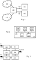
- the Fig. 1 schematically illustrates a system in which the present invention can be implemented.
- the system of Fig. 1 comprises a device 100 connected to a first communication network 120, such as the Internet, and to a second communication network 110, such as a satellite network.
- a first communication network 120 such as the Internet
- a second communication network 110 such as a satellite network.
- the device 100 is adapted to receive, via the first 110 and second 120 networks, audio and / or video content in the form of data streams broadcast continuously (“live streaming” in English).
- the device 100 is adapted to receive audio and / or video content via the first 110 and second 120 networks simultaneously.
- the device 100 is also connected via a link 130 to a first device 131 consumer of audiovisual content, such as a screen, and via a link 140 to a second device 141 consumer of audiovisual content, such as a digital recorder or a another screen.
- the device 100 is a device for broadcasting audio and / or video content.
- the links 130 and 140 can be wired or wireless.
- the device 100 When the device 100 receives audio and / or video content via the first 110 and second 120 networks simultaneously, the device 100 therefore receives two data streams. These two data streams are generally time-shifted since these two data streams do not follow the same propagation paths. It would be the same if the device 100 received a data stream from a communication network and if separate preprocesses, therefore with distinct latency, were applied to this data stream to form two data streams injected into the device 100.
- the data streams are preferably according to a format defined by the MPEG group (“Moving Picture Experts Group” in English), such as for example the MPEG-2 format.
- the audio and / or video content as broadcast by the device 100 via the link 130 and / or the link 140 is either in the form of a stream of decoded data, that is to say decompressed and therefore the device 100 comprises a corresponding decoder, either in the form of a stream of non-decoded data, that is to say compressed and therefore the consumer devices 131 and 141 respectively comprise corresponding decoders.
- the device 100 is previously configured to broadcast the audio and / or video content from a first data stream among these two data streams.
- the behavior of the device 100 following a detection of a command to switch the broadcasting of audio and / or video content from the first data stream to a second data stream from these two data streams, is detailed below in relationship with the Fig. 4 .
- a modular cutting of at least part of the device 100 to implement this behavior is detailed below in relation to the Fig. 3 .
- the Fig. 2 schematically illustrates an example of hardware architecture of the device 100.
- the device 100 then comprises, connected by a communication bus 220: a processor or CPU (“Central Processing Unit” in English) 210; a random access memory RAM (“Random Access Memory” in English) 211; a ROM (“Read Only Memory”) 212; a storage unit or a storage medium reader, such as an SD (“Secure Digital” in English) card reader or a HDD (“Hard Disk Drive”) 213; and a set of interfaces 214 making it possible to receive audiovisual content via the first 110 and second 120 networks and to transmit audiovisual content via the first 130 and second 140 links.
- a processor or CPU Central Processing Unit” in English
- RAM Random Access Memory
- ROM Read Only Memory
- storage unit or a storage medium reader such as an SD (“Secure Digital” in English) card reader or a HDD (“Hard Disk Drive”) 213
- SD Secure Digital
- HDD Hard Disk Drive
- the processor 210 is capable of executing instructions loaded into the RAM 211 from the ROM 212, from an external memory (not shown), from a storage medium, or from a communication network. When device 100 is powered up, processor 210 is capable of reading instructions from RAM 211 and executing them. These instructions form a computer program causing the implementation, by the processor 210, of all or part of the modules, algorithms and steps described below.
- all or part of the modules, algorithms and steps described below can be implemented in software form by execution of a set of instructions by a programmable machine, such as a DSP ("Digital Signal Processor” in English) or a microcontroller. All or part of the algorithms and steps described below can also be implemented in hardware form by a machine or a dedicated component, such as an FPGA ("Field-Programmable Gate Array” in English) or an ASIC ("Application-Specific Integrated Circuit ”.
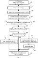
- the Fig. 3 schematically illustrates an example of modular cutting of at least part of the device 100.
- the device 100 includes a first reception module 301 adapted to receive the first data stream, denoted F1 on the Fig. 3 , representative of the audio and / or video content, and a second module 302 adapted to receive the second data stream, denoted F2 on the Fig. 3 , representative of the audio and / or video content.
- the first 301 and second 302 reception modules include a tuner (“tuner” in English) making it possible to select a data stream representative of audio and / or video content from a plurality of data streams streamed and representative of audio and / or video content.
- the device 100 further comprises an arbitration module 320 making it possible to select from the first F1 and second F2 data streams, and to switch from the first F1 data stream to the second F2 data stream, following a detection of a toggle order.
- the selected stream is thus transmitted by the arbitration module 320, for example via the link 130.
- the device 100 further comprises a module 310 for determining by correlation of a mark of the audio and / or video content in the first data stream F1 and in the second data stream F2, connected to the first 301 and second 302 reception modules .
- the purpose of the correlation determination module 310 is to find the same image and / or the same sound in the first F1 and second F2 data streams.
- the correlation determination module 310 finds a mark in the audio and / or video content, and determines a time offset between the first data stream F1 and the second data stream F2, based on timestamp information. associated with this reference in each of the first F1 and second F2 data streams.
- the correlation determination module 310 then supplies information representative of this time difference to the arbitration module 320.
- the device 100 further comprises a module 311 for reducing the broadcast rate of the first data stream F1, which is interposed between the first reception module 301 and the arbitration module 320.
- the arbitration module 320 requires the module 311 to reduce the broadcast rate (" frame rate " in English) of the first F1 data stream, and this up to with absorption of the time difference. The broadcasting of the first data stream F1 is thus temporarily slowed down, then the arbitration module 320 can switch from the first data stream F1 to the second data stream F2.
- the device 100 further comprises a module 312 for pausing the second data stream F2, which is interposed between the first reception module 301 and the arbitration module 320.
- This principle is called time shifting in English terminology.
- the arbitration module 320 requires the module 312 to pause the data stream F2, and this until absorption of the time difference.
- the second data stream F2 is paused by rerouting the second data stream F2 in a memory, which is activated for reading as soon as the time offset is absorbed.
- any data from the F2 stream written at an instant T is only made available to the arbitration module 320 at a time T + D, where D represents the time offset between the first F1 and second F2 data stream.
- the arbitration module 320 can switch from the first data stream F1 to the second data stream F2.
- the Fig. 3 considers the case of a switchover from the first data stream F1 to the second data stream F2. If a switchover were also to be allowed, the module 311 should also include a function for pausing the first data stream F1, and the module 312 should also include a function for reducing the transmission rate of the second data stream F2.
- the Fig. 4 schematically illustrates a configuration management algorithm of the device 100.
- the device 100 is configured so that the device 100 receives the first F1 and second F2 data streams representative of the audio and / or video content.
- the device 100 is further configured so that the device 100 broadcasts, for example via the link 130, the first data stream F1 or a decompressed version of the first data stream F1.
- the arbitration module 320 As part of the modular cutting of the Fig. 3 , such a configuration is applied by the arbitration module 320.
- the device 100 detects a broadcast switching order from the first data stream D1 to the second data stream F2.
- the first data stream F1 comes from a tuner allowing to receive a first set of television channels
- the second data stream F2 comes from a tuner making it possible to receive a second set of television channels
- the tuner from which the first data stream F1 is derived must be released to allow another consumer device to receive a television channel only present in the first set of television channels.
- the device 100 analyzes by correlation the data of the stream F1 and of the stream F2, or of data resulting from a decoding of the stream F1 and of the stream F2. As part of the modular cutting of the Fig. 3 , such a correlation analysis is carried out by the module 310.
- the audio and / or video data of the first F1 and second F2 stream being obtained from the same digitization or encoding operation, these audio and / or video data are assumed to be identical, when 'they correspond to the same portion of the audio and / or video content.
- Correlation analysis consists in locating in the second flow F2 (or in the first stream F1) at which position is a predetermined set of data of the first stream F1 (respectively of the second stream F2).
- the device 100 can also select audio and / or video data from the first stream F1 (or from the second stream F2), as an image, and search in the second stream F2 (respectively in the first stream F1), data with a correlation rate higher than a predefined threshold.
- the device 100 can also select audio and / or video data from the first stream F1 (or from the second stream F2), such as an image, and search in the second data stream F2 (respectively in the first data stream F1), data having the highest correlation rate among a set of data. This makes it possible to manage the case where the data of the first F1 and second F2 streams are not obtained by the same scanning or encoding operation, or if noise has been inserted into the data of at least one of the F1 and F2 data flow.
- the device 100 can perform the correlation analysis on the basis of luminance histograms of the images of the first F1 and second F2 data stream.
- the device 100 can implement the dynamic time deformation algorithm DTW ("Dynamic Time Wraping" in English), to measure similarities in audio data.
- DTW Dynamic Time Wraping
- the correlation analysis is carried out by determining acoustic imprints on portions of the first F1 and second F2 data flow.
- the device 100 determines a first acoustic footprint corresponding to a predefined duration of the content for the first data stream F1 (or the second data stream F2) and determines a second acoustic footprint for different data sets of the second stream F2 (respectively of the first flow F1) corresponding to the same predefined duration.
- An acoustic fingerprint is summed up deterministically from an audio signal.
- the first acoustic imprint serves as a reference and the device 100 uses a sliding window on the data of the second stream F2 to compare the second acoustic footprint with the first acoustic footprint until a correlation rate greater than a predefined threshold is obtained.
- the determination of such fingerprints involves, for example, a detection of frequency peaks and a determination of the difference between these frequency peaks in a simplified spectrogram of the audio content.
- the device 100 proceeds beforehand to a corresponding decompression of at least part of the audio data and / or video of the first F1 and second F2 streams, to allow the implementation of the correlation analysis operation.
- the device 100 can perform this decoding operation only on the images with internal coding, that is to say the images intra , and do not practice this decoding operation only on images with predictive coding, that is to say inter images .
- the device 100 determines a mark of the audio and / or video content in the first data stream F1 and in the second data stream F2.
- the device 100 determines a time offset between the first data stream F1 and the second data stream F2 to based on time stamping information associated with the marker in each of the first F1 and second F2 data streams.
- the time stamping information may be representative of times at which the corresponding audio and / or video data must be supported by a decoder and which is called DTS (“Decode Time Stamp” in English), or be representative of times at which the corresponding audio and / or video data must be presented to a consumer device and which is called PTS (“ Time Stamp presentation ”.
- DTS Decode Time Stamp
- PTS Time Stamp presentation
- the device 100 stores information representative of the time offset determines and uses this information to configure the correlation analysis for a next switchover between the first F1 and second F2 data stream.
- the stored information defines for example the starting point of the correlation analysis during this next changeover.
- a step 405 as a function of the determined time offset, the device 100 determines whether the second data stream F2 is late with respect to the first data stream F1. If this is the case, a step 407 is carried out; otherwise, a step 406 is carried out.
- a step 406 as a function of the determined time offset, the device 100 determines whether the second data stream F2 is ahead of the first data stream F1. If this is the case, a step 409 is carried out; otherwise, there is no time offset and a step 410 is performed.
- step 407 the second data stream F2 lags behind the first data stream F1.
- the device 100 then reduces the diffusion rate, called frame rate, of the first data stream F1 until the time offset is absorbed.
- the device 100 modifies the timestamp information of the data of the first data stream F1 accordingly, in particular the PTS information within the framework of an MPEG stream.
- the arbitration module 320 requires the module 311 to activate the rate reduction function of the second data stream F2, until the time offset is absorbed.
- An optional step 408 can be performed, otherwise step 410 is performed.
- step 408 when the data of the first F1 and second F2 stream are audio or audiovisual data, the device 100 performs audio processing on the data in order to preserve the pitch (“pitch”). that is, in order to avoid that, because of the slowing down linked to the decrease in the speed of the diffusion of the first data stream F1, the sound rendering is more serious.
- a phase vocoder (“Phase Vocoder” in English) can be implemented, using algorithms from Flanagan, Griffin and Lim, Laroche and Dolson, or Roebel.
- a SOLA (“Synchonized OverLap-Add”) algorithm can be implemented, thus limiting the consumption of processing resources to maintain the pitch. Audio processing is applied until the time difference is absorbed. Then, step 410 is implemented.
- step 409 the second data stream F2 is ahead of the first data stream F1.
- the device 100 then pauses the second data stream F2 until the time offset is absorbed.
- the arbitration module 320 requires the module 312 to activate the pause function of the second data stream F2, until absorption of the time offset. Then, step 410 is implemented.
- step 410 the device 100 switches to a configuration such that the device 100 broadcasts, for example via the link 130, the second data stream F2 or a decompressed version of the second data stream F2.
- a configuration is applied by the arbitration module 320.
Landscapes
- Engineering & Computer Science (AREA)
- Signal Processing (AREA)
- Multimedia (AREA)
- Computer Networks & Wireless Communication (AREA)
- Two-Way Televisions, Distribution Of Moving Picture Or The Like (AREA)
- Compression Or Coding Systems Of Tv Signals (AREA)
- Signal Processing For Digital Recording And Reproducing (AREA)
Claims (9)
- Verfahren, welches von einer Vorrichtung (100) zur Verbreitung von Video- oder Audio-Video-Inhalten durchgeführt wird, wobei die Vorrichtung einen ersten Datenstrom, der für einen Video- oder Audio-Video-Inhalt repräsentativ ist, und einen zweiten Datenstrom, der für den Video- oder Audio-Video-Inhalt repräsentativ ist, empfängt, wobei die Vorrichtung zuvor dafür konfiguriert wird (400), den Video- oder Audio-Video-Inhalt anhand des ersten Datenstroms zu verbreiten,
wobei das Verfahren so ausgelegt ist, dass die Vorrichtung vor einem Umschalten (410) vom ersten Datenstrom zum zweiten Datenstrom die folgenden Schritte ausführt:- Anhalten (409) des zweiten Datenstroms bis zum Ausgleich einer zeitlichen Verschiebung, wenn die zeitliche Verschiebung anzeigt, dass der erste Datenstrom gegenüber dem zweiten Datenstrom verzögert ist;- Verringerung (407) einer Bildfrequenz des ersten Datenstroms bis zum Ausgleich der zeitlichen Verschiebung, wenn die zeitliche Verschiebung anzeigt, dass der erste Datenstrom dem zweiten Datenstrom vorauseilt,wobei das Verfahren dadurch gekennzeichnet ist, dass die Vorrichtung im Anschluss an eine Erkennung (401) eines Befehls zum Umschalten der Verbreitung des Video- oder Audio-Video-Inhalts vom ersten Datenstrom zum zweiten Datenstrom die folgenden Schritte ausführt:- Bestimmung (402,403), durch Korrelation, eines Kennzeichens des Video- oder Audio-Video-Inhalts im ersten Datenstrom und im zweiten Datenstrom, wobei die Korrelation auf der Basis von Leuchtdichte-Histogrammen von Bildern des ersten und zweiten Datenstroms durchgeführt wird;- Bestimmung (404) der zeitlichen Verschiebung zwischen dem ersten Datenstrom und dem zweiten Datenstrom anhand einer Zeitstempelinformation, die dem Kennzeichen im ersten und im zweiten Datenstrom jeweils zugeordnet ist. - Verfahren nach Anspruch 1, wobei das Anhalten des zweiten Datenstroms durch Umleitung des zweiten Datenstroms in einen Speicher realisiert wird, wobei der Speicher zum Lesen aktiviert wird, sobald der Ausgleich der zeitlichen Verschiebung erfolgt ist.
- Verfahren nach einem der Ansprüche 1 und 2, wobei, wenn die Daten des ersten und zweiten Stroms komprimierte Daten sind, die Vorrichtung vor dem Schritt der Bestimmung durch Korrelation einen Schritt der Datendekomprimierung durchführt und die Korrelation auf der Basis der dekomprimierten Daten durchführt.
- Verfahren nach Anspruch 3, wobei, wenn die Daten des ersten und zweiten Stroms durch prädiktive Codierung komprimierte Video- oder Audio-Video-Daten sind, die Vorrichtung die Dekomprimierung nur an Intra-Bildern für die Korrelation durchführt.
- Verfahren nach einem der Ansprüche 1 bis 4, wobei die Vorrichtung eine Information speichert, die für die zeitliche Verschiebung repräsentativ ist, und diese Information verwendet, um die Korrelation für ein nächstes Umschalten zwischen dem ersten und zweiten Datenstrom zu parametrieren.
- Verfahren nach einem der Ansprüche 1 bis 5, wobei, wenn die Daten des ersten und zweiten Stroms Audio-Video-Daten sind und wenn die Vorrichtung die Bildfrequenz des ersten Datenstroms bis zum Ausgleich der zeitlichen Verschiebung verringert, die Vorrichtung eine Audioverarbeitung (408) an den Daten des ersten Stroms durchführt, um dessen Tonhöhe beizubehalten.
- Vorrichtung (100) zur Verbreitung von Video- oder Audio-Video-Inhalten, wobei die Vorrichtung Mittel zum Empfangen eines ersten Datenstroms, der für einen Video- oder Audio-Video-Inhalt repräsentativ ist, und eines zweiten Datenstroms, der für den Video- oder Audio-Video-Inhalt repräsentativ ist, aufweist, wobei die Vorrichtung dafür konfiguriert ist (400), den Video- oder Audio-Video-Inhalt anhand des ersten Datenstroms zu verbreiten,
wobei die Vorrichtung so ausgelegt ist, dass die Vorrichtung vor einem Umschalten (410) vom ersten Datenstrom zum zweiten Datenstrom einsetzt:- Mittel zum Anhalten (409) des zweiten Datenstroms bis zum Ausgleich einer zeitlichen Verschiebung, wenn die zeitliche Verschiebung anzeigt, dass der erste Datenstrom gegenüber dem zweiten Datenstrom verzögert ist;- Mittel zur Verringerung (407) einer Bildfrequenz des ersten Datenstroms bis zum Ausgleich der zeitlichen Verschiebung, wenn die zeitliche Verschiebung anzeigt,dass der erste Datenstrom dem zweiten Datenstrom vorauseilt,
dadurch gekennzeichnet, dass die Vorrichtung im Anschluss an eine Erkennung (401) eines Befehls zum Umschalten der Verbreitung des Video- oder Audio-Video-Inhalts vom ersten Datenstrom zum zweiten Datenstrom einsetzt:- Mittel zur Bestimmung, durch Korrelation (402, 403), eines Kennzeichens des Video- oder Audio-Video-Inhalts im ersten Datenstrom und im zweiten Datenstrom, wobei die Korrelation auf der Basis von Leuchtdichte-Histogrammen von Bildern des ersten und zweiten Datenstroms durchgeführt wird;- Mittel zur Bestimmung (404) der zeitlichen Verschiebung zwischen dem ersten Datenstrom und dem zweiten Datenstrom anhand einer Zeitstempelinformation, die dem Kennzeichen im ersten und im zweiten Datenstrom jeweils zugeordnet ist. - Computerprogramm, welches Anweisungen zur Durchführung des Verfahrens nach einem der Ansprüche 1 bis 6 durch einen Prozessor, wenn das Programm von dem Prozessor ausgeführt wird, umfasst.
- Aufzeichnungsmedium, auf welchem ein Computerprogramm gespeichert ist, das Anweisungen zur Durchführung des Verfahrens nach einem der Ansprüche 1 bis 6 durch einen Prozessor, wenn das Programm von dem Prozessor ausgeführt wird, umfasst.
Applications Claiming Priority (2)
| Application Number | Priority Date | Filing Date | Title |
|---|---|---|---|
| FR1261880A FR2999370B1 (fr) | 2012-12-11 | 2012-12-11 | Dispositif et procede de basculement depuis un premier flux vers un second flux |
| PCT/EP2013/075454 WO2014090643A1 (fr) | 2012-12-11 | 2013-12-04 | Dispositif et procede de basculement depuis un premier flux de donnees vers un second flux de donnees |
Publications (2)
| Publication Number | Publication Date |
|---|---|
| EP2932633A1 EP2932633A1 (de) | 2015-10-21 |
| EP2932633B1 true EP2932633B1 (de) | 2020-02-05 |
Family
ID=47754748
Family Applications (1)
| Application Number | Title | Priority Date | Filing Date |
|---|---|---|---|
| EP13801547.4A Active EP2932633B1 (de) | 2012-12-11 | 2013-12-04 | Gerät und verfahren zum umschalten zwischen einem ersten datenstrom und einem zweiten datenstrom |
Country Status (6)
| Country | Link |
|---|---|
| US (1) | US9832248B2 (de) |
| EP (1) | EP2932633B1 (de) |
| CN (1) | CN105052060B (de) |
| BR (1) | BR112015013536A2 (de) |
| FR (1) | FR2999370B1 (de) |
| WO (1) | WO2014090643A1 (de) |
Families Citing this family (8)
| Publication number | Priority date | Publication date | Assignee | Title |
|---|---|---|---|---|
| US9900362B2 (en) * | 2014-02-11 | 2018-02-20 | Kiswe Mobile Inc. | Methods and apparatus for reducing latency shift in switching between distinct content streams |
| US10210545B2 (en) * | 2015-12-30 | 2019-02-19 | TCL Research America Inc. | Method and system for grouping devices in a same space for cross-device marketing |
| CN107197394B (zh) * | 2017-05-05 | 2019-12-13 | 中广热点云科技有限公司 | 一种视频播放中音频切换的方法 |
| US11159635B2 (en) | 2019-05-07 | 2021-10-26 | Hulu, LLC | Soft server push in video streaming |
| FR3113448B1 (fr) * | 2020-08-11 | 2022-08-12 | Continental Automotive | Suivi de station FM en audio non synchronisé |
| US11831943B2 (en) | 2021-10-26 | 2023-11-28 | Apple Inc. | Synchronized playback of media content |
| US12010260B2 (en) * | 2021-11-03 | 2024-06-11 | Capital One Services, Llc | Detecting synthetic sounds in call audio |
| US12613958B2 (en) | 2024-07-02 | 2026-04-28 | Wiz, Inc. | Temporal cause analysis of cybersecurity events |
Family Cites Families (10)
| Publication number | Priority date | Publication date | Assignee | Title |
|---|---|---|---|---|
| US6415326B1 (en) * | 1998-09-15 | 2002-07-02 | Microsoft Corporation | Timeline correlation between multiple timeline-altered media streams |
| EP1073224A3 (de) * | 1999-05-07 | 2002-08-14 | Sony International (Europe) GmbH | Strategie für die Umschaltung auf alternative Frequenzen für DRM |
| AU5140200A (en) * | 1999-05-26 | 2000-12-18 | Enounce, Incorporated | Method and apparatus for controlling time-scale modification during multi-media broadcasts |
| EP1233556A1 (de) * | 2001-02-16 | 2002-08-21 | Sony International (Europe) GmbH | Empfänger für den Empfang von Rundfunksignalen mit Verwendung von zwei Empfängern, für den Empfang eines Rundfunksignals das auf zwei unterschiedlichen Rundfunkfrequenzen oder mit zwei unterschiedlichen Übertragungssystemen übertragen wird |
| US20020116178A1 (en) * | 2001-04-13 | 2002-08-22 | Crockett Brett G. | High quality time-scaling and pitch-scaling of audio signals |
| US8107535B2 (en) * | 2003-06-10 | 2012-01-31 | Rensselaer Polytechnic Institute (Rpi) | Method and apparatus for scalable motion vector coding |
| US9047236B2 (en) * | 2008-06-06 | 2015-06-02 | Amazon Technologies, Inc. | Client side stream switching |
| US20110149753A1 (en) * | 2009-12-21 | 2011-06-23 | Qualcomm Incorporated | Switching between media broadcast streams having varying levels of quality |
| EP2416318B1 (de) * | 2010-08-04 | 2016-10-12 | Nero Ag | Mehrsprachenpufferung während der Medienwiedergabe |
| US20130331972A1 (en) * | 2010-11-15 | 2013-12-12 | Egonocast | System and method for synchronizing an application with audio content |
-
2012
- 2012-12-11 FR FR1261880A patent/FR2999370B1/fr not_active Expired - Fee Related
-
2013
- 2013-12-04 CN CN201380072741.4A patent/CN105052060B/zh not_active Expired - Fee Related
- 2013-12-04 WO PCT/EP2013/075454 patent/WO2014090643A1/fr not_active Ceased
- 2013-12-04 US US14/650,404 patent/US9832248B2/en not_active Expired - Fee Related
- 2013-12-04 BR BR112015013536A patent/BR112015013536A2/pt active Search and Examination
- 2013-12-04 EP EP13801547.4A patent/EP2932633B1/de active Active
Non-Patent Citations (1)
| Title |
|---|
| None * |
Also Published As
| Publication number | Publication date |
|---|---|
| WO2014090643A1 (fr) | 2014-06-19 |
| US9832248B2 (en) | 2017-11-28 |
| CN105052060A (zh) | 2015-11-11 |
| BR112015013536A2 (pt) | 2017-07-11 |
| US20150312304A1 (en) | 2015-10-29 |
| EP2932633A1 (de) | 2015-10-21 |
| CN105052060B (zh) | 2018-04-03 |
| FR2999370B1 (fr) | 2018-04-27 |
| FR2999370A1 (fr) | 2014-06-13 |
Similar Documents
| Publication | Publication Date | Title |
|---|---|---|
| EP2932633B1 (de) | Gerät und verfahren zum umschalten zwischen einem ersten datenstrom und einem zweiten datenstrom | |
| US8788933B2 (en) | Time-shifted presentation of media streams | |
| US10720188B2 (en) | Systems and methods of thumbnail generation | |
| US20150271546A1 (en) | Synchronized provision of social media content with time-delayed video program events | |
| EP3681162B1 (de) | Nahtlose inhaltskodierung und -übertragung | |
| US20140201368A1 (en) | Method and apparatus for enforcing behavior of dash or other clients | |
| EP3167617B1 (de) | Verfahren und vorrichtung zur fernaufzeichnung von videoprogrammen | |
| EP2870773B1 (de) | Datenaufzeichnungsvorrichtung und verfahren im zusammenhang mit einer verschiebungsfunktion auf einem aufzeichnungsmedium | |
| EP3317799B1 (de) | Verfahren zur bereitstellung von geschütztem multimediainhalt | |
| EP3501125B1 (de) | Verfahren zur synchronisation von zwei datenströmen sowie anwendung dieses verfahrens im rahmen eines empfängers | |
| FR3075543B1 (fr) | Procede de telechargement de chaine pour le zapping d'une chaine numerique en fonction du comportement utilisateur | |
| FR2954650A1 (fr) | " procede et dispositif d'enregistrement et de diffusion video par decalage temporel, dit " timeshifting "." | |
| FR3131160A1 (fr) | Procédé de restitution d’un contenu multimédia, programme d’ordinateur et terminal lecteur de flux multimédia correspondants. | |
| WO2009119031A1 (ja) | デジタルテレビジョン放送受信装置 | |
| WO2020188097A1 (fr) | Procédé de restitution de contenus de personnalisation d'un flux radiophonique principal | |
| FR3043219A1 (fr) | Procede de mise en veille automatique d'un equipement multimedia | |
| KR20150070039A (ko) | 오디오 콘텐츠의 가속화된 복원을 위한 방법 및 관련 장치 |
Legal Events
| Date | Code | Title | Description |
|---|---|---|---|
| PUAI | Public reference made under article 153(3) epc to a published international application that has entered the european phase |
Free format text: ORIGINAL CODE: 0009012 |
|
| 17P | Request for examination filed |
Effective date: 20150707 |
|
| AK | Designated contracting states |
Kind code of ref document: A1 Designated state(s): AL AT BE BG CH CY CZ DE DK EE ES FI FR GB GR HR HU IE IS IT LI LT LU LV MC MK MT NL NO PL PT RO RS SE SI SK SM TR |
|
| AX | Request for extension of the european patent |
Extension state: BA ME |
|
| DAX | Request for extension of the european patent (deleted) | ||
| RAP1 | Party data changed (applicant data changed or rights of an application transferred) |
Owner name: SAGEMCOM SAS |
|
| RAP1 | Party data changed (applicant data changed or rights of an application transferred) |
Owner name: SAGEMCOM BROADBAND SAS |
|
| STAA | Information on the status of an ep patent application or granted ep patent |
Free format text: STATUS: EXAMINATION IS IN PROGRESS |
|
| 17Q | First examination report despatched |
Effective date: 20190329 |
|
| GRAP | Despatch of communication of intention to grant a patent |
Free format text: ORIGINAL CODE: EPIDOSNIGR1 |
|
| STAA | Information on the status of an ep patent application or granted ep patent |
Free format text: STATUS: GRANT OF PATENT IS INTENDED |
|
| INTG | Intention to grant announced |
Effective date: 20190801 |
|
| GRAS | Grant fee paid |
Free format text: ORIGINAL CODE: EPIDOSNIGR3 |
|
| GRAA | (expected) grant |
Free format text: ORIGINAL CODE: 0009210 |
|
| STAA | Information on the status of an ep patent application or granted ep patent |
Free format text: STATUS: THE PATENT HAS BEEN GRANTED |
|
| AK | Designated contracting states |
Kind code of ref document: B1 Designated state(s): AL AT BE BG CH CY CZ DE DK EE ES FI FR GB GR HR HU IE IS IT LI LT LU LV MC MK MT NL NO PL PT RO RS SE SI SK SM TR |
|
| REG | Reference to a national code |
Ref country code: GB Ref legal event code: FG4D Free format text: NOT ENGLISH |
|
| REG | Reference to a national code |
Ref country code: AT Ref legal event code: REF Ref document number: 1230609 Country of ref document: AT Kind code of ref document: T Effective date: 20200215 |
|
| REG | Reference to a national code |
Ref country code: DE Ref legal event code: R096 Ref document number: 602013065505 Country of ref document: DE |
|
| REG | Reference to a national code |
Ref country code: IE Ref legal event code: FG4D Free format text: LANGUAGE OF EP DOCUMENT: FRENCH |
|
| REG | Reference to a national code |
Ref country code: CH Ref legal event code: EP |
|
| REG | Reference to a national code |
Ref country code: NL Ref legal event code: MP Effective date: 20200205 |
|
| PG25 | Lapsed in a contracting state [announced via postgrant information from national office to epo] |
Ref country code: PT Free format text: LAPSE BECAUSE OF FAILURE TO SUBMIT A TRANSLATION OF THE DESCRIPTION OR TO PAY THE FEE WITHIN THE PRESCRIBED TIME-LIMIT Effective date: 20200628 Ref country code: FI Free format text: LAPSE BECAUSE OF FAILURE TO SUBMIT A TRANSLATION OF THE DESCRIPTION OR TO PAY THE FEE WITHIN THE PRESCRIBED TIME-LIMIT Effective date: 20200205 Ref country code: NO Free format text: LAPSE BECAUSE OF FAILURE TO SUBMIT A TRANSLATION OF THE DESCRIPTION OR TO PAY THE FEE WITHIN THE PRESCRIBED TIME-LIMIT Effective date: 20200505 Ref country code: RS Free format text: LAPSE BECAUSE OF FAILURE TO SUBMIT A TRANSLATION OF THE DESCRIPTION OR TO PAY THE FEE WITHIN THE PRESCRIBED TIME-LIMIT Effective date: 20200205 |
|
| REG | Reference to a national code |
Ref country code: LT Ref legal event code: MG4D |
|
| PG25 | Lapsed in a contracting state [announced via postgrant information from national office to epo] |
Ref country code: GR Free format text: LAPSE BECAUSE OF FAILURE TO SUBMIT A TRANSLATION OF THE DESCRIPTION OR TO PAY THE FEE WITHIN THE PRESCRIBED TIME-LIMIT Effective date: 20200506 Ref country code: HR Free format text: LAPSE BECAUSE OF FAILURE TO SUBMIT A TRANSLATION OF THE DESCRIPTION OR TO PAY THE FEE WITHIN THE PRESCRIBED TIME-LIMIT Effective date: 20200205 Ref country code: BG Free format text: LAPSE BECAUSE OF FAILURE TO SUBMIT A TRANSLATION OF THE DESCRIPTION OR TO PAY THE FEE WITHIN THE PRESCRIBED TIME-LIMIT Effective date: 20200505 Ref country code: IS Free format text: LAPSE BECAUSE OF FAILURE TO SUBMIT A TRANSLATION OF THE DESCRIPTION OR TO PAY THE FEE WITHIN THE PRESCRIBED TIME-LIMIT Effective date: 20200605 Ref country code: SE Free format text: LAPSE BECAUSE OF FAILURE TO SUBMIT A TRANSLATION OF THE DESCRIPTION OR TO PAY THE FEE WITHIN THE PRESCRIBED TIME-LIMIT Effective date: 20200205 Ref country code: LV Free format text: LAPSE BECAUSE OF FAILURE TO SUBMIT A TRANSLATION OF THE DESCRIPTION OR TO PAY THE FEE WITHIN THE PRESCRIBED TIME-LIMIT Effective date: 20200205 |
|
| PG25 | Lapsed in a contracting state [announced via postgrant information from national office to epo] |
Ref country code: NL Free format text: LAPSE BECAUSE OF FAILURE TO SUBMIT A TRANSLATION OF THE DESCRIPTION OR TO PAY THE FEE WITHIN THE PRESCRIBED TIME-LIMIT Effective date: 20200205 |
|
| PG25 | Lapsed in a contracting state [announced via postgrant information from national office to epo] |
Ref country code: ES Free format text: LAPSE BECAUSE OF FAILURE TO SUBMIT A TRANSLATION OF THE DESCRIPTION OR TO PAY THE FEE WITHIN THE PRESCRIBED TIME-LIMIT Effective date: 20200205 Ref country code: CZ Free format text: LAPSE BECAUSE OF FAILURE TO SUBMIT A TRANSLATION OF THE DESCRIPTION OR TO PAY THE FEE WITHIN THE PRESCRIBED TIME-LIMIT Effective date: 20200205 Ref country code: LT Free format text: LAPSE BECAUSE OF FAILURE TO SUBMIT A TRANSLATION OF THE DESCRIPTION OR TO PAY THE FEE WITHIN THE PRESCRIBED TIME-LIMIT Effective date: 20200205 Ref country code: DK Free format text: LAPSE BECAUSE OF FAILURE TO SUBMIT A TRANSLATION OF THE DESCRIPTION OR TO PAY THE FEE WITHIN THE PRESCRIBED TIME-LIMIT Effective date: 20200205 Ref country code: EE Free format text: LAPSE BECAUSE OF FAILURE TO SUBMIT A TRANSLATION OF THE DESCRIPTION OR TO PAY THE FEE WITHIN THE PRESCRIBED TIME-LIMIT Effective date: 20200205 Ref country code: SM Free format text: LAPSE BECAUSE OF FAILURE TO SUBMIT A TRANSLATION OF THE DESCRIPTION OR TO PAY THE FEE WITHIN THE PRESCRIBED TIME-LIMIT Effective date: 20200205 Ref country code: RO Free format text: LAPSE BECAUSE OF FAILURE TO SUBMIT A TRANSLATION OF THE DESCRIPTION OR TO PAY THE FEE WITHIN THE PRESCRIBED TIME-LIMIT Effective date: 20200205 Ref country code: SK Free format text: LAPSE BECAUSE OF FAILURE TO SUBMIT A TRANSLATION OF THE DESCRIPTION OR TO PAY THE FEE WITHIN THE PRESCRIBED TIME-LIMIT Effective date: 20200205 |
|
| REG | Reference to a national code |
Ref country code: DE Ref legal event code: R097 Ref document number: 602013065505 Country of ref document: DE |
|
| REG | Reference to a national code |
Ref country code: AT Ref legal event code: MK05 Ref document number: 1230609 Country of ref document: AT Kind code of ref document: T Effective date: 20200205 |
|
| PLBE | No opposition filed within time limit |
Free format text: ORIGINAL CODE: 0009261 |
|
| STAA | Information on the status of an ep patent application or granted ep patent |
Free format text: STATUS: NO OPPOSITION FILED WITHIN TIME LIMIT |
|
| 26N | No opposition filed |
Effective date: 20201106 |
|
| PG25 | Lapsed in a contracting state [announced via postgrant information from national office to epo] |
Ref country code: IT Free format text: LAPSE BECAUSE OF FAILURE TO SUBMIT A TRANSLATION OF THE DESCRIPTION OR TO PAY THE FEE WITHIN THE PRESCRIBED TIME-LIMIT Effective date: 20200205 Ref country code: AT Free format text: LAPSE BECAUSE OF FAILURE TO SUBMIT A TRANSLATION OF THE DESCRIPTION OR TO PAY THE FEE WITHIN THE PRESCRIBED TIME-LIMIT Effective date: 20200205 |
|
| PGFP | Annual fee paid to national office [announced via postgrant information from national office to epo] |
Ref country code: GB Payment date: 20201123 Year of fee payment: 8 Ref country code: FR Payment date: 20201120 Year of fee payment: 8 Ref country code: DE Payment date: 20201119 Year of fee payment: 8 |
|
| PG25 | Lapsed in a contracting state [announced via postgrant information from national office to epo] |
Ref country code: PL Free format text: LAPSE BECAUSE OF FAILURE TO SUBMIT A TRANSLATION OF THE DESCRIPTION OR TO PAY THE FEE WITHIN THE PRESCRIBED TIME-LIMIT Effective date: 20200205 Ref country code: SI Free format text: LAPSE BECAUSE OF FAILURE TO SUBMIT A TRANSLATION OF THE DESCRIPTION OR TO PAY THE FEE WITHIN THE PRESCRIBED TIME-LIMIT Effective date: 20200205 |
|
| REG | Reference to a national code |
Ref country code: CH Ref legal event code: PL |
|
| PG25 | Lapsed in a contracting state [announced via postgrant information from national office to epo] |
Ref country code: MC Free format text: LAPSE BECAUSE OF FAILURE TO SUBMIT A TRANSLATION OF THE DESCRIPTION OR TO PAY THE FEE WITHIN THE PRESCRIBED TIME-LIMIT Effective date: 20200205 |
|
| REG | Reference to a national code |
Ref country code: BE Ref legal event code: MM Effective date: 20201231 |
|
| PG25 | Lapsed in a contracting state [announced via postgrant information from national office to epo] |
Ref country code: LU Free format text: LAPSE BECAUSE OF NON-PAYMENT OF DUE FEES Effective date: 20201204 Ref country code: IE Free format text: LAPSE BECAUSE OF NON-PAYMENT OF DUE FEES Effective date: 20201204 |
|
| PG25 | Lapsed in a contracting state [announced via postgrant information from national office to epo] |
Ref country code: LI Free format text: LAPSE BECAUSE OF NON-PAYMENT OF DUE FEES Effective date: 20201231 Ref country code: CH Free format text: LAPSE BECAUSE OF NON-PAYMENT OF DUE FEES Effective date: 20201231 |
|
| PG25 | Lapsed in a contracting state [announced via postgrant information from national office to epo] |
Ref country code: TR Free format text: LAPSE BECAUSE OF FAILURE TO SUBMIT A TRANSLATION OF THE DESCRIPTION OR TO PAY THE FEE WITHIN THE PRESCRIBED TIME-LIMIT Effective date: 20200205 Ref country code: MT Free format text: LAPSE BECAUSE OF FAILURE TO SUBMIT A TRANSLATION OF THE DESCRIPTION OR TO PAY THE FEE WITHIN THE PRESCRIBED TIME-LIMIT Effective date: 20200205 Ref country code: CY Free format text: LAPSE BECAUSE OF FAILURE TO SUBMIT A TRANSLATION OF THE DESCRIPTION OR TO PAY THE FEE WITHIN THE PRESCRIBED TIME-LIMIT Effective date: 20200205 |
|
| PG25 | Lapsed in a contracting state [announced via postgrant information from national office to epo] |
Ref country code: MK Free format text: LAPSE BECAUSE OF FAILURE TO SUBMIT A TRANSLATION OF THE DESCRIPTION OR TO PAY THE FEE WITHIN THE PRESCRIBED TIME-LIMIT Effective date: 20200205 Ref country code: AL Free format text: LAPSE BECAUSE OF FAILURE TO SUBMIT A TRANSLATION OF THE DESCRIPTION OR TO PAY THE FEE WITHIN THE PRESCRIBED TIME-LIMIT Effective date: 20200205 |
|
| REG | Reference to a national code |
Ref country code: DE Ref legal event code: R119 Ref document number: 602013065505 Country of ref document: DE |
|
| PG25 | Lapsed in a contracting state [announced via postgrant information from national office to epo] |
Ref country code: BE Free format text: LAPSE BECAUSE OF NON-PAYMENT OF DUE FEES Effective date: 20201231 |
|
| GBPC | Gb: european patent ceased through non-payment of renewal fee |
Effective date: 20211204 |
|
| PG25 | Lapsed in a contracting state [announced via postgrant information from national office to epo] |
Ref country code: GB Free format text: LAPSE BECAUSE OF NON-PAYMENT OF DUE FEES Effective date: 20211204 Ref country code: DE Free format text: LAPSE BECAUSE OF NON-PAYMENT OF DUE FEES Effective date: 20220701 |
|
| PG25 | Lapsed in a contracting state [announced via postgrant information from national office to epo] |
Ref country code: FR Free format text: LAPSE BECAUSE OF NON-PAYMENT OF DUE FEES Effective date: 20211231 |