EP2932464B1 - Procédé d'affichage et système d'aide à la navigation - Google Patents
Procédé d'affichage et système d'aide à la navigation Download PDFInfo
- Publication number
- EP2932464B1 EP2932464B1 EP13802630.7A EP13802630A EP2932464B1 EP 2932464 B1 EP2932464 B1 EP 2932464B1 EP 13802630 A EP13802630 A EP 13802630A EP 2932464 B1 EP2932464 B1 EP 2932464B1
- Authority
- EP
- European Patent Office
- Prior art keywords
- image
- pixels
- headset
- orientation
- size
- Prior art date
- Legal status (The legal status is an assumption and is not a legal conclusion. Google has not performed a legal analysis and makes no representation as to the accuracy of the status listed.)
- Active
Links
Images

Classifications
-
- G—PHYSICS
- G06—COMPUTING OR CALCULATING; COUNTING
- G06T—IMAGE DATA PROCESSING OR GENERATION, IN GENERAL
- G06T19/00—Manipulating 3D models or images for computer graphics
- G06T19/006—Mixed reality
-
- G—PHYSICS
- G02—OPTICS
- G02B—OPTICAL ELEMENTS, SYSTEMS OR APPARATUS
- G02B27/00—Optical systems or apparatus not provided for by any of the groups G02B1/00 - G02B26/00, G02B30/00
- G02B27/01—Head-up displays
- G02B27/017—Head mounted
-
- G—PHYSICS
- G06—COMPUTING OR CALCULATING; COUNTING
- G06F—ELECTRIC DIGITAL DATA PROCESSING
- G06F3/00—Input arrangements for transferring data to be processed into a form capable of being handled by the computer; Output arrangements for transferring data from processing unit to output unit, e.g. interface arrangements
- G06F3/01—Input arrangements or combined input and output arrangements for interaction between user and computer
- G06F3/011—Arrangements for interaction with the human body, e.g. for user immersion in virtual reality
-
- G—PHYSICS
- G06—COMPUTING OR CALCULATING; COUNTING
- G06T—IMAGE DATA PROCESSING OR GENERATION, IN GENERAL
- G06T3/00—Geometric image transformations in the plane of the image
- G06T3/40—Scaling of whole images or parts thereof, e.g. expanding or contracting
- G06T3/4038—Image mosaicing, e.g. composing plane images from plane sub-images
-
- G—PHYSICS
- G02—OPTICS
- G02B—OPTICAL ELEMENTS, SYSTEMS OR APPARATUS
- G02B27/00—Optical systems or apparatus not provided for by any of the groups G02B1/00 - G02B26/00, G02B30/00
- G02B27/01—Head-up displays
- G02B27/0101—Head-up displays characterised by optical features
- G02B2027/0138—Head-up displays characterised by optical features comprising image capture systems, e.g. camera
Definitions
- the present invention relates to a display method.
- the invention also relates to a navigation aid system and to a vehicle comprising the navigation aid system.
- the targeted field is that of the aid to the navigation of an air or land vehicle, and more specifically, the improvement of the perception of the external environment of the vehicle.
- the operator is often equipped with an augmented reality helmet.
- a helmet allows the operator to simultaneously view on the same semi-transparent screen part of the environment in direct vision and projected images of the same part of the environment acquired by a detection device.
- the detection device comprises several cameras operating in the infrared.
- the operator visualizes the environment part both in the visible band (in direct view) and in an infrared band (via the detection device). The operator thus has more information on the environment of the vehicle than by direct vision.
- the latency time translates for the operator by a latency in content and a latency in position.
- the latency in content is manifested in the observation of a car moving in the environment from the rear to the front while the driver and the vehicle remain fixed.
- the vehicle observed in direct vision will be ahead of the projected vehicle.
- it should limit the latency content to 80 milliseconds (ms).
- the latency in position is manifested especially when the vehicle is fixed with an environment without moving parts and the driver moves his head. It exists then an offset between the orientation of the pilot at the time of the projection of the image on the helmet screen and the direction of sight of the cameras at the time of acquisition of the images by the cameras.
- the projected image and the image displayed in direct vision overlap without being superimposed, although the environment remains unchanged between the moment of acquisition of the images and the instant of projection of the images on the helmet screen. .
- a phenomenon of dragging occurs. Therefore, it is necessary to limit the latency in position to 20 ms.
- the image processing unit which displays improved vision images based on a plurality of image sources.
- the image processing unit comprises a serial processing unit and a parallel processing unit.
- the serial processing unit performs the low volume data computations required by the parallel processing unit for displaying an image.
- the serial processing unit precalculates transformations required to convert the data from each source to a main coordinate system.
- the parallel processing unit uses the transformations and correlates the data from each source with a pixel-by-pixel display, so as to provide display data with reduced latency.
- a method of displaying an image on a screen of a helmet of a navigation aid system includes the helmet and a calculator.
- the display method comprises the steps successive measurement of the orientation of the helmet of the operator with the helmet for processing a first image having a first number of pixels to obtain a first processed image, extraction of a portion of the first image processed according to the measured orientation of the headset to obtain a second image, the second image having a second number of pixels strictly less than the first number of pixels and sending by the computer to the headset of the second image for display on the screen.
- the invention also relates to a method of displaying images on the respective screens of at least two helmets of a navigation aid system.
- the navigation aid system comprises at least two helmets, a plurality of cameras adapted to acquire at least one image of a part of an environment and a computer.
- the method comprises, for each screen, the steps of the method as previously described.
- the invention also relates to a navigation aid system for a vehicle comprising a computer and at least one helmet, the computer being adapted to the implementation of the method as previously described.
- the invention also relates to a vehicle comprising the navigation aid system as previously described.
- the invention also relates to a display method according to claim 1.
- the invention also relates to a vehicle navigation aid system according to claim 8.
- the invention also relates to a vehicle according to claim 9.
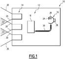
- the vehicle 10 represented at figure 1 is an air or land vehicle.
- the vehicle 10 is a helicopter.
- the vehicle 10 comprises a system 12 for aiding navigation.
- the navigation aid system 12 comprises a plurality of cameras 14, a helmet 16 and a computer 18.
- the navigation aid system 12 comprises three cameras 14.
- the three cameras 14 are arranged on a portion of the vehicle 10 so that the cameras 14 are adapted to acquire images of the environment of the vehicle 10.
- the cameras 14 are part of the vehicle hull 10.
- the fields of observation of the cameras 14 determine the parts of the environment in which the cameras 14 are suitable for acquiring images.
- the fields of observation are delimited on the figure 1 by continuous lines 20.
- the fields of the cameras 14 overlap as indicated by the areas 22 of overlap highlighted by broken lines. This makes it possible to avoid the existence of unobserved angular areas near a vehicle operator.
- the cameras 14 are suitable for detecting photons emitted by the environment in the infrared.
- the cameras 14 are able to detect photons emitted by the environment in the visible spectrum with a low level of light (for example at dusk). Such visible cameras are sometimes referred to by the acronym "BNL" for "Low Level of Light”.
- the helmet 16 is intended for an operator of the vehicle 10.
- the helmet 16 comprises a screen 24, an image projector 26 and a gyrometer 28.
- the image projector 26 is adapted to project an image on the screen 24.
- the screen 24 is semi-transparent to allow the operator to simultaneously view the outside environment of the vehicle 10 and an image projected by the projector 26. For this reason, the headset 16 is qualified as "augmented reality headset 16". .
- the gyro 28 is capable of delivering information that makes it possible to determine the orientation of the helmet 16 with respect to a reference R taking into account the movements of the vehicle provided by an inertial unit of the vehicle or by any other means.
- the gyro 28 delivers measurements of angular derivatives along three axes of an inertial reference.
- the reference R is the orientation of the helmet 16 in which the operator looks straight ahead.
- the own motion of the vehicle 10 is taken into account to reduce the orientation of the helmet 16 calculated from the information of the gyro 28 in an absolute reference in the vehicle mark.
- the orientation of the helmet 16 of the operator is then marked by two angles relative to the reference R.
- the helmet 16 is connected to the computer 18 by a cable 30.
- the computer 18 is adapted to receive the images acquired by the cameras 14, to process the received images and then to display them on the screen 24 of the helmet 16 by the projector 26.
- the computer 18 is, for example, a graphics processor.
- a graphics processor, or GPU Graphics Processing Unit
- GPU Graphics Processing Unit
- the computer 18 is a programmable logic circuit.
- a circuit is a logic integrated circuit that can be reprogrammed after its manufacture.
- the computer 18 is an FPGA (the English acronym field-programmable gate array) which is a set of gates in situ programmable.
- the cameras 14 simultaneously acquire three images of the external environment of the vehicle 10. The three images are transmitted to the computer 18.
- the computer 18 then implements a method of displaying an image on the screen 24 of the headset 16 with reference to the flowchart of FIG. figure 2 .
- the method comprises a step 100 of reception by the computer 18 of the images of the environment part acquired by the three cameras 14.
- the method also comprises a step 102 of determining the orientation of the helmet 16 with respect to the reference R.
- Step 102 is implemented by a measurement with the gyro 28.
- the orientation of the helmet 16 determined is a predicted orientation using a predictive filtering on the movements of the operator.
- the method then comprises a step 104 of merging the images received at the reception step 100 to obtain a merged image IF of the environment.
- the overlapping zones 22 are imaged by several cameras 14.
- the melting step comprises calculating the value of the pixel by calculating a linear combination of the pixel value for one of the two cameras 14 and the value of the same pixel for the other camera 14.
- the coefficients of the linear combination depend on the distance of the pixel considered to the pixels situated at the periphery of the images to be merged.
- the fusion step 104 thus makes it possible to obtain the merged image IF which is a panoramic image of the environment.
- the merged image IF associates a point of the field of view of the operator with a pixel value.
- the coordinates of this point can be expressed in several references. In particular, the coordinates of the point are locatable in the same reference mark which makes it possible to locate the orientation of the operator.
- only the images that will be used to produce the final image are merged. For example, if the operator looks to the left of the vehicle, the images acquired by the cameras on the right are not merged; only the images acquired by the cameras on the left and in the center are used for the fusion.
- the method also includes a first step 106 of extracting a portion of the merged image IF to obtain a first image I1.
- the first image I1 has a first number of pixels N1.
- the first image I1 has a first size T1 in a first direction of the image and a second size T2 in a second direction of the image perpendicular to the first direction of the image.
- the first size T1 is 1200 pixels and the second size T2 is 1000 pixels.
- the first number N1 of pixels is then 1200 x 1000 pixels.
- the first step 106 of extracting the portion of the merged image IF is a function of the orientation of the helmet 16 determined in the determination step 102.
- the orientation of the helmet 16 determined in the determination step 102 is the center of the first image I1.
- the first extraction step 106 is implemented in two stages. First, it is determined which pixel of the merged image IF corresponds to the orientation of the helmet 16 determined in the determination step 102. In a second step, a rectangle of sizes T1 and T2 is extracted around this pixel. The pixels belonging to this rectangle form the first image I1.
- the method also includes a step 108 of processing the first image I1 to obtain a first processed image IT1.
- Step 108 of processing aims to improve the quality of the first image I1.
- the processing comprises the implementation of a treatment of the brightness of the first image called "tone mapping".
- tone mapping a treatment of the brightness of the first image
- the processed image IT1 has the same number of pixels as the first image I1.
- the method also comprises a step 110 for measuring the orientation of the helmet 16 after the step 108 of processing the first image I1.
- This measurement is, for example, implemented with the gyro 28 of the helmet 16.
- the movement of the vehicle between the instants of implementation of measurement steps 102 and 110 is also taken into account.
- the movement of the vehicle is, for example, obtained using an inertial unit.
- the method also comprises a second step 112 for extracting a portion of the first processed image IT1 as a function of the orientation measured at the measurement step 110 to obtain a second image I2.
- the measured orientation is the center of the second image I2.
- the second image I2 has a second number of pixels N2.
- the second number of pixels N2 is fixed by the size of the image that is displayable on the screen 24 because the dimensions of the screen 24 are finished.
- the second number of pixels N2 is 1024 ⁇ 768 pixels.
- the second number of pixels N2 is strictly less than the first number of pixels N1.
- the ratio between the first number of pixels N1 and the second number of pixels N2 is chosen on the basis of an increase in the amplitude of the movements of the helmet 16 of the operator during the duration of the processing steps 104, 106 and 108 .
- the duration of processing steps 104, 106 and 108 is limited. Typically, the duration of the processing step is 30 ms.
- An increase in the amplitude of the movements of the operator's helmet 16 during the duration of the processing step 108 thus makes it possible to obtain a set of possible orientations for the helmet of the operator.
- a central pixel on the merged image IF is determinable. Assuming that the field of view of the operator is fixed, i.e., the number of pixels N2 is fixed, for each central pixel determined by correspondence with a possible orientation, a set of N2 pixels is also determined. In other words, at each possible orientation, it is associated N2 pixels around the determined central pixel.
- the pixels that belong to the different sets of N2 pixels for the different possible orientations are the pixels of the first image I1.
- the ratio between the first number of pixels N1 and the second number of pixels N2 is less than 160%.
- the ratio between the first number of pixels N1 and the second number of pixels N2 is 152%.
- the ratio between the first number of pixels N1 and the second number of pixels N2 is less than 130%.
- the second image I2 has a third size T3 in the first direction of the image and a fourth size T4 in the second direction of the image.
- the ratio between the first size T1 and the third size T3 is equal to the ratio between the second size T2 and the fourth size T4.
- the method then comprises a step 114 of sending data relating to the second image I2 from the computer 18 to the headset 16.
- the projector 16 then displays the second image on the screen 24.
- the operator then simultaneously displays on the screen 24 a part of the environment in direct vision and projected images of the same part of the environment acquired by the cameras 14.
- the display method has two extractions. Indeed, the first extraction step 106 is a "coarse extraction” step whereas the second extraction step 112 is a "fine extraction” step.
- processing step 108 is implemented on a part of the merged image IF only. This makes it possible to limit the duration of step 108 of treatment.
- step 114 of sending the data and the step 110 of measuring the orientation of the helmet 16 of the operator are synchronized since the duration of the second extraction step 112 is very short.
- the second image I2 displayed takes into account a measured orientation of the helmet 16 and not a predicted orientation.
- the position of the second image I2 is more precise than in the state of the art.
- the method therefore makes it possible to greatly reduce the latency in position of the image displayed to the operator.
- the method is easy to implement.
- the navigation aid system 12 is suitable for several operators.
- the pilot and the co-pilot are required to work at the same time to observe the same environment, each observing a different part of the environment.
- the first extraction step 106, the processing step 108, the measurement step 110, the second extraction step 112, and the data sending step 114 are simultaneously implemented. for the different operators using the navigation aid system 12.
Landscapes
- Engineering & Computer Science (AREA)
- Physics & Mathematics (AREA)
- General Physics & Mathematics (AREA)
- Theoretical Computer Science (AREA)
- General Engineering & Computer Science (AREA)
- Computer Graphics (AREA)
- Human Computer Interaction (AREA)
- Computer Hardware Design (AREA)
- Software Systems (AREA)
- Optics & Photonics (AREA)
- Navigation (AREA)
- Radar, Positioning & Navigation (AREA)
- Remote Sensing (AREA)
- Automation & Control Theory (AREA)
Priority Applications (1)
| Application Number | Priority Date | Filing Date | Title |
|---|---|---|---|
| PL13802630T PL2932464T3 (pl) | 2012-12-17 | 2013-12-10 | Sposób wyświetlania i system wspomagający nawigację |
Applications Claiming Priority (2)
| Application Number | Priority Date | Filing Date | Title |
|---|---|---|---|
| FR1203441A FR2999759B1 (fr) | 2012-12-17 | 2012-12-17 | Procede d'affichage et systeme d'aide a la navigation |
| PCT/EP2013/076042 WO2014095480A1 (fr) | 2012-12-17 | 2013-12-10 | Procede d'affichage et systeme d'aide a la navigation |
Publications (2)
| Publication Number | Publication Date |
|---|---|
| EP2932464A1 EP2932464A1 (fr) | 2015-10-21 |
| EP2932464B1 true EP2932464B1 (fr) | 2019-09-11 |
Family
ID=48607311
Family Applications (1)
| Application Number | Title | Priority Date | Filing Date |
|---|---|---|---|
| EP13802630.7A Active EP2932464B1 (fr) | 2012-12-17 | 2013-12-10 | Procédé d'affichage et système d'aide à la navigation |
Country Status (6)
| Country | Link |
|---|---|
| US (1) | US10311639B2 (pl) |
| EP (1) | EP2932464B1 (pl) |
| FR (1) | FR2999759B1 (pl) |
| IL (1) | IL239460B (pl) |
| PL (1) | PL2932464T3 (pl) |
| WO (1) | WO2014095480A1 (pl) |
Families Citing this family (2)
| Publication number | Priority date | Publication date | Assignee | Title |
|---|---|---|---|---|
| GB201713052D0 (en) | 2017-08-15 | 2017-09-27 | Imagination Tech Ltd | Single pass rendering for head mounted displays |
| US11082635B2 (en) | 2019-05-02 | 2021-08-03 | The Boeing Company | Systems and methods for video display |
Family Cites Families (7)
| Publication number | Priority date | Publication date | Assignee | Title |
|---|---|---|---|---|
| US7180476B1 (en) * | 1999-06-30 | 2007-02-20 | The Boeing Company | Exterior aircraft vision system using a helmet-mounted display |
| US7148861B2 (en) * | 2003-03-01 | 2006-12-12 | The Boeing Company | Systems and methods for providing enhanced vision imaging with decreased latency |
| US7486291B2 (en) * | 2003-07-08 | 2009-02-03 | Berson Barry L | Systems and methods using enhanced vision to provide out-the-window displays for a device |
| US7499079B2 (en) * | 2004-03-18 | 2009-03-03 | Northrop Grumman Corporation | Multi-camera image stitching for a distributed aperture system |
| US20110291918A1 (en) * | 2010-06-01 | 2011-12-01 | Raytheon Company | Enhancing Vision Using An Array Of Sensor Modules |
| US9690099B2 (en) * | 2010-12-17 | 2017-06-27 | Microsoft Technology Licensing, Llc | Optimized focal area for augmented reality displays |
| US9213185B1 (en) * | 2012-01-06 | 2015-12-15 | Google Inc. | Display scaling based on movement of a head-mounted display |
-
2012
- 2012-12-17 FR FR1203441A patent/FR2999759B1/fr not_active Expired - Fee Related
-
2013
- 2013-12-10 PL PL13802630T patent/PL2932464T3/pl unknown
- 2013-12-10 WO PCT/EP2013/076042 patent/WO2014095480A1/fr not_active Ceased
- 2013-12-10 US US14/652,137 patent/US10311639B2/en active Active
- 2013-12-10 EP EP13802630.7A patent/EP2932464B1/fr active Active
-
2015
- 2015-06-16 IL IL239460A patent/IL239460B/en active IP Right Grant
Non-Patent Citations (1)
| Title |
|---|
| ASHIKHMIN M ED - GIBSON S ET AL: "A TONE MAPPING ALGORITHM FOR HIGH CONTRAST IMAGES", RENDERING TECHNIQUES 2002. EUROGRAPHICS WORKSHOP PROCEEDINGS. PISA, ITALY, JUNE 26 - 28, 2002, 26 June 2002 (2002-06-26), pages 145 - 155, XP001232388 * |
Also Published As
| Publication number | Publication date |
|---|---|
| US10311639B2 (en) | 2019-06-04 |
| IL239460B (en) | 2019-02-28 |
| US20150332503A1 (en) | 2015-11-19 |
| FR2999759A1 (fr) | 2014-06-20 |
| FR2999759B1 (fr) | 2017-09-01 |
| WO2014095480A1 (fr) | 2014-06-26 |
| IL239460A0 (en) | 2015-07-30 |
| PL2932464T3 (pl) | 2020-03-31 |
| EP2932464A1 (fr) | 2015-10-21 |
Similar Documents
| Publication | Publication Date | Title |
|---|---|---|
| KR102298378B1 (ko) | 정보 처리 장치, 정보 처리 방법, 및 프로그램 | |
| EP2891953B1 (en) | Eye vergence detection on a display | |
| JP6176541B2 (ja) | 情報表示装置、情報表示方法及びプログラム | |
| WO2012118575A2 (en) | Alignment control in an augmented reality headpiece | |
| US20180164114A1 (en) | Vehicle Navigation Display System And Method Thereof | |
| FR3028767A1 (fr) | Systeme video pour le pilotage d'un drone en mode immersif | |
| CN107615755A (zh) | 头戴式显示器、平视显示器和影像显示方法 | |
| EP3465086B1 (fr) | Equipement optronique de vision pour un vehicule terrestre | |
| JP5533766B2 (ja) | 車両用表示装置 | |
| CN106970748A (zh) | 基于环境光颜色自动调节车载hud显示颜色的方法和系统 | |
| WO2012020558A1 (ja) | 画像処理装置、画像処理方法、表示装置、表示方法およびプログラム | |
| JP2017126009A (ja) | 表示制御装置、表示制御方法、およびプログラム | |
| WO2018134897A1 (ja) | 位置姿勢検出装置、ar表示装置、位置姿勢検出方法およびar表示方法 | |
| EP3355277A1 (fr) | Procédé d'affichage sur un écran d'au moins une représentation d'un objet, programme d'ordinateur, dispositif et appareil électroniques d'affichage associés | |
| EP2932464B1 (fr) | Procédé d'affichage et système d'aide à la navigation | |
| FR3030092A1 (fr) | Procede de representation tridimensionnelle d'une scene | |
| JP4857159B2 (ja) | 車両運転支援装置 | |
| FR3071650A1 (fr) | Procede de realite augmentee pour la visualisation de plats de restaurant | |
| FR3033903A1 (fr) | Systeme d'aide a la navigation d'un aeronef avec ecran d'affichage tete haute et camera. | |
| EP3871074A1 (fr) | Procédé de pilotage de l'affichage d'informations sur un bandeau d'écran équipant une passerelle de bateau | |
| EP2469869A1 (fr) | Procédé de suppression d'un masque de cockpit et système de visualisation de casque associé | |
| JP7192907B2 (ja) | 俯瞰映像生成装置及び俯瞰映像生成方法 | |
| US12306403B2 (en) | Electronic device and method for controlling electronic device | |
| US20250209685A1 (en) | Image processing apparatus for performing reprojection processing for reducing cg image delay and control method for image processing apparatus | |
| WO2016129241A1 (ja) | 表示制御装置及び表示システム |
Legal Events
| Date | Code | Title | Description |
|---|---|---|---|
| PUAI | Public reference made under article 153(3) epc to a published international application that has entered the european phase |
Free format text: ORIGINAL CODE: 0009012 |
|
| 17P | Request for examination filed |
Effective date: 20150612 |
|
| AK | Designated contracting states |
Kind code of ref document: A1 Designated state(s): AL AT BE BG CH CY CZ DE DK EE ES FI FR GB GR HR HU IE IS IT LI LT LU LV MC MK MT NL NO PL PT RO RS SE SI SK SM TR |
|
| AX | Request for extension of the european patent |
Extension state: BA ME |
|
| DAX | Request for extension of the european patent (deleted) | ||
| 17Q | First examination report despatched |
Effective date: 20160713 |
|
| STAA | Information on the status of an ep patent application or granted ep patent |
Free format text: STATUS: EXAMINATION IS IN PROGRESS |
|
| GRAP | Despatch of communication of intention to grant a patent |
Free format text: ORIGINAL CODE: EPIDOSNIGR1 |
|
| STAA | Information on the status of an ep patent application or granted ep patent |
Free format text: STATUS: GRANT OF PATENT IS INTENDED |
|
| INTG | Intention to grant announced |
Effective date: 20190408 |
|
| GRAS | Grant fee paid |
Free format text: ORIGINAL CODE: EPIDOSNIGR3 |
|
| GRAA | (expected) grant |
Free format text: ORIGINAL CODE: 0009210 |
|
| STAA | Information on the status of an ep patent application or granted ep patent |
Free format text: STATUS: THE PATENT HAS BEEN GRANTED |
|
| AK | Designated contracting states |
Kind code of ref document: B1 Designated state(s): AL AT BE BG CH CY CZ DE DK EE ES FI FR GB GR HR HU IE IS IT LI LT LU LV MC MK MT NL NO PL PT RO RS SE SI SK SM TR |
|
| REG | Reference to a national code |
Ref country code: GB Ref legal event code: FG4D Free format text: NOT ENGLISH |
|
| REG | Reference to a national code |
Ref country code: CH Ref legal event code: EP |
|
| REG | Reference to a national code |
Ref country code: AT Ref legal event code: REF Ref document number: 1179433 Country of ref document: AT Kind code of ref document: T Effective date: 20190915 |
|
| REG | Reference to a national code |
Ref country code: DE Ref legal event code: R096 Ref document number: 602013060439 Country of ref document: DE Ref country code: IE Ref legal event code: FG4D Free format text: LANGUAGE OF EP DOCUMENT: FRENCH |
|
| REG | Reference to a national code |
Ref country code: RO Ref legal event code: EPE |
|
| REG | Reference to a national code |
Ref country code: SE Ref legal event code: TRGR |
|
| REG | Reference to a national code |
Ref country code: EE Ref legal event code: FG4A Ref document number: E018431 Country of ref document: EE Effective date: 20191125 Ref country code: NL Ref legal event code: MP Effective date: 20190911 |
|
| REG | Reference to a national code |
Ref country code: LT Ref legal event code: MG4D |
|
| PG25 | Lapsed in a contracting state [announced via postgrant information from national office to epo] |
Ref country code: HR Free format text: LAPSE BECAUSE OF FAILURE TO SUBMIT A TRANSLATION OF THE DESCRIPTION OR TO PAY THE FEE WITHIN THE PRESCRIBED TIME-LIMIT Effective date: 20190911 Ref country code: NO Free format text: LAPSE BECAUSE OF FAILURE TO SUBMIT A TRANSLATION OF THE DESCRIPTION OR TO PAY THE FEE WITHIN THE PRESCRIBED TIME-LIMIT Effective date: 20191211 Ref country code: LT Free format text: LAPSE BECAUSE OF FAILURE TO SUBMIT A TRANSLATION OF THE DESCRIPTION OR TO PAY THE FEE WITHIN THE PRESCRIBED TIME-LIMIT Effective date: 20190911 Ref country code: BG Free format text: LAPSE BECAUSE OF FAILURE TO SUBMIT A TRANSLATION OF THE DESCRIPTION OR TO PAY THE FEE WITHIN THE PRESCRIBED TIME-LIMIT Effective date: 20191211 |
|
| PG25 | Lapsed in a contracting state [announced via postgrant information from national office to epo] |
Ref country code: LV Free format text: LAPSE BECAUSE OF FAILURE TO SUBMIT A TRANSLATION OF THE DESCRIPTION OR TO PAY THE FEE WITHIN THE PRESCRIBED TIME-LIMIT Effective date: 20190911 Ref country code: AL Free format text: LAPSE BECAUSE OF FAILURE TO SUBMIT A TRANSLATION OF THE DESCRIPTION OR TO PAY THE FEE WITHIN THE PRESCRIBED TIME-LIMIT Effective date: 20190911 Ref country code: ES Free format text: LAPSE BECAUSE OF FAILURE TO SUBMIT A TRANSLATION OF THE DESCRIPTION OR TO PAY THE FEE WITHIN THE PRESCRIBED TIME-LIMIT Effective date: 20190911 Ref country code: RS Free format text: LAPSE BECAUSE OF FAILURE TO SUBMIT A TRANSLATION OF THE DESCRIPTION OR TO PAY THE FEE WITHIN THE PRESCRIBED TIME-LIMIT Effective date: 20190911 |
|
| REG | Reference to a national code |
Ref country code: AT Ref legal event code: MK05 Ref document number: 1179433 Country of ref document: AT Kind code of ref document: T Effective date: 20190911 |
|
| REG | Reference to a national code |
Ref country code: GR Ref legal event code: EP Ref document number: 20190403616 Country of ref document: GR Effective date: 20200318 |
|
| PG25 | Lapsed in a contracting state [announced via postgrant information from national office to epo] |
Ref country code: NL Free format text: LAPSE BECAUSE OF FAILURE TO SUBMIT A TRANSLATION OF THE DESCRIPTION OR TO PAY THE FEE WITHIN THE PRESCRIBED TIME-LIMIT Effective date: 20190911 Ref country code: PT Free format text: LAPSE BECAUSE OF FAILURE TO SUBMIT A TRANSLATION OF THE DESCRIPTION OR TO PAY THE FEE WITHIN THE PRESCRIBED TIME-LIMIT Effective date: 20200113 Ref country code: AT Free format text: LAPSE BECAUSE OF FAILURE TO SUBMIT A TRANSLATION OF THE DESCRIPTION OR TO PAY THE FEE WITHIN THE PRESCRIBED TIME-LIMIT Effective date: 20190911 Ref country code: IT Free format text: LAPSE BECAUSE OF FAILURE TO SUBMIT A TRANSLATION OF THE DESCRIPTION OR TO PAY THE FEE WITHIN THE PRESCRIBED TIME-LIMIT Effective date: 20190911 |
|
| PG25 | Lapsed in a contracting state [announced via postgrant information from national office to epo] |
Ref country code: SK Free format text: LAPSE BECAUSE OF FAILURE TO SUBMIT A TRANSLATION OF THE DESCRIPTION OR TO PAY THE FEE WITHIN THE PRESCRIBED TIME-LIMIT Effective date: 20190911 Ref country code: SM Free format text: LAPSE BECAUSE OF FAILURE TO SUBMIT A TRANSLATION OF THE DESCRIPTION OR TO PAY THE FEE WITHIN THE PRESCRIBED TIME-LIMIT Effective date: 20190911 Ref country code: IS Free format text: LAPSE BECAUSE OF FAILURE TO SUBMIT A TRANSLATION OF THE DESCRIPTION OR TO PAY THE FEE WITHIN THE PRESCRIBED TIME-LIMIT Effective date: 20200224 |
|
| REG | Reference to a national code |
Ref country code: DE Ref legal event code: R097 Ref document number: 602013060439 Country of ref document: DE |
|
| PLBE | No opposition filed within time limit |
Free format text: ORIGINAL CODE: 0009261 |
|
| STAA | Information on the status of an ep patent application or granted ep patent |
Free format text: STATUS: NO OPPOSITION FILED WITHIN TIME LIMIT |
|
| PG2D | Information on lapse in contracting state deleted |
Ref country code: IS |
|
| PG25 | Lapsed in a contracting state [announced via postgrant information from national office to epo] |
Ref country code: DK Free format text: LAPSE BECAUSE OF FAILURE TO SUBMIT A TRANSLATION OF THE DESCRIPTION OR TO PAY THE FEE WITHIN THE PRESCRIBED TIME-LIMIT Effective date: 20190911 Ref country code: IS Free format text: LAPSE BECAUSE OF FAILURE TO SUBMIT A TRANSLATION OF THE DESCRIPTION OR TO PAY THE FEE WITHIN THE PRESCRIBED TIME-LIMIT Effective date: 20200112 |
|
| REG | Reference to a national code |
Ref country code: CH Ref legal event code: PL |
|
| 26N | No opposition filed |
Effective date: 20200615 |
|
| PG25 | Lapsed in a contracting state [announced via postgrant information from national office to epo] |
Ref country code: SI Free format text: LAPSE BECAUSE OF FAILURE TO SUBMIT A TRANSLATION OF THE DESCRIPTION OR TO PAY THE FEE WITHIN THE PRESCRIBED TIME-LIMIT Effective date: 20190911 Ref country code: MC Free format text: LAPSE BECAUSE OF FAILURE TO SUBMIT A TRANSLATION OF THE DESCRIPTION OR TO PAY THE FEE WITHIN THE PRESCRIBED TIME-LIMIT Effective date: 20190911 |
|
| PG25 | Lapsed in a contracting state [announced via postgrant information from national office to epo] |
Ref country code: LU Free format text: LAPSE BECAUSE OF NON-PAYMENT OF DUE FEES Effective date: 20191210 Ref country code: IE Free format text: LAPSE BECAUSE OF NON-PAYMENT OF DUE FEES Effective date: 20191210 |
|
| PG25 | Lapsed in a contracting state [announced via postgrant information from national office to epo] |
Ref country code: CH Free format text: LAPSE BECAUSE OF NON-PAYMENT OF DUE FEES Effective date: 20191231 Ref country code: LI Free format text: LAPSE BECAUSE OF NON-PAYMENT OF DUE FEES Effective date: 20191231 |
|
| PG25 | Lapsed in a contracting state [announced via postgrant information from national office to epo] |
Ref country code: CY Free format text: LAPSE BECAUSE OF FAILURE TO SUBMIT A TRANSLATION OF THE DESCRIPTION OR TO PAY THE FEE WITHIN THE PRESCRIBED TIME-LIMIT Effective date: 20190911 |
|
| PG25 | Lapsed in a contracting state [announced via postgrant information from national office to epo] |
Ref country code: MT Free format text: LAPSE BECAUSE OF FAILURE TO SUBMIT A TRANSLATION OF THE DESCRIPTION OR TO PAY THE FEE WITHIN THE PRESCRIBED TIME-LIMIT Effective date: 20190911 Ref country code: HU Free format text: LAPSE BECAUSE OF FAILURE TO SUBMIT A TRANSLATION OF THE DESCRIPTION OR TO PAY THE FEE WITHIN THE PRESCRIBED TIME-LIMIT; INVALID AB INITIO Effective date: 20131210 |
|
| PG25 | Lapsed in a contracting state [announced via postgrant information from national office to epo] |
Ref country code: MK Free format text: LAPSE BECAUSE OF FAILURE TO SUBMIT A TRANSLATION OF THE DESCRIPTION OR TO PAY THE FEE WITHIN THE PRESCRIBED TIME-LIMIT Effective date: 20190911 |
|
| P01 | Opt-out of the competence of the unified patent court (upc) registered |
Effective date: 20230522 |
|
| PGFP | Annual fee paid to national office [announced via postgrant information from national office to epo] |
Ref country code: DE Payment date: 20241211 Year of fee payment: 12 |
|
| PGFP | Annual fee paid to national office [announced via postgrant information from national office to epo] |
Ref country code: GB Payment date: 20251229 Year of fee payment: 13 |
|
| PGFP | Annual fee paid to national office [announced via postgrant information from national office to epo] |
Ref country code: FI Payment date: 20251124 Year of fee payment: 13 |
|
| PGFP | Annual fee paid to national office [announced via postgrant information from national office to epo] |
Ref country code: FR Payment date: 20251230 Year of fee payment: 13 |
|
| PGFP | Annual fee paid to national office [announced via postgrant information from national office to epo] |
Ref country code: TR Payment date: 20251205 Year of fee payment: 13 Ref country code: BE Payment date: 20251226 Year of fee payment: 13 Ref country code: GR Payment date: 20251124 Year of fee payment: 13 |
|
| PGFP | Annual fee paid to national office [announced via postgrant information from national office to epo] |
Ref country code: SE Payment date: 20251218 Year of fee payment: 13 |
|
| PGFP | Annual fee paid to national office [announced via postgrant information from national office to epo] |
Ref country code: CZ Payment date: 20251210 Year of fee payment: 13 |
|
| PGFP | Annual fee paid to national office [announced via postgrant information from national office to epo] |
Ref country code: PL Payment date: 20251121 Year of fee payment: 13 |
|
| PGFP | Annual fee paid to national office [announced via postgrant information from national office to epo] |
Ref country code: EE Payment date: 20251124 Year of fee payment: 13 |
|
| PGFP | Annual fee paid to national office [announced via postgrant information from national office to epo] |
Ref country code: RO Payment date: 20251127 Year of fee payment: 13 |