EP2932418B1 - Metadata driven real-time analytics framework - Google Patents
Metadata driven real-time analytics framework Download PDFInfo
- Publication number
- EP2932418B1 EP2932418B1 EP13818085.6A EP13818085A EP2932418B1 EP 2932418 B1 EP2932418 B1 EP 2932418B1 EP 13818085 A EP13818085 A EP 13818085A EP 2932418 B1 EP2932418 B1 EP 2932418B1
- Authority
- EP
- European Patent Office
- Prior art keywords
- real
- application
- data analytics
- time data
- definition
- Prior art date
- Legal status (The legal status is an assumption and is not a legal conclusion. Google has not performed a legal analysis and makes no representation as to the accuracy of the status listed.)
- Active
Links
Images


Classifications
-
- G—PHYSICS
- G06—COMPUTING OR CALCULATING; COUNTING
- G06F—ELECTRIC DIGITAL DATA PROCESSING
- G06F8/00—Arrangements for software engineering
- G06F8/20—Software design
-
- G—PHYSICS
- G06—COMPUTING OR CALCULATING; COUNTING
- G06F—ELECTRIC DIGITAL DATA PROCESSING
- G06F8/00—Arrangements for software engineering
- G06F8/30—Creation or generation of source code
- G06F8/31—Programming languages or programming paradigms
-
- G—PHYSICS
- G06—COMPUTING OR CALCULATING; COUNTING
- G06F—ELECTRIC DIGITAL DATA PROCESSING
- G06F21/00—Security arrangements for protecting computers, components thereof, programs or data against unauthorised activity
- G06F21/30—Authentication, i.e. establishing the identity or authorisation of security principals
- G06F21/31—User authentication
-
- G—PHYSICS
- G06—COMPUTING OR CALCULATING; COUNTING
- G06F—ELECTRIC DIGITAL DATA PROCESSING
- G06F21/00—Security arrangements for protecting computers, components thereof, programs or data against unauthorised activity
- G06F21/30—Authentication, i.e. establishing the identity or authorisation of security principals
- G06F21/44—Program or device authentication
-
- G—PHYSICS
- G06—COMPUTING OR CALCULATING; COUNTING
- G06F—ELECTRIC DIGITAL DATA PROCESSING
- G06F8/00—Arrangements for software engineering
- G06F8/30—Creation or generation of source code
- G06F8/38—Creation or generation of source code for implementing user interfaces
-
- G—PHYSICS
- G06—COMPUTING OR CALCULATING; COUNTING
- G06F—ELECTRIC DIGITAL DATA PROCESSING
- G06F8/00—Arrangements for software engineering
- G06F8/60—Software deployment
- G06F8/61—Installation
-
- G—PHYSICS
- G06—COMPUTING OR CALCULATING; COUNTING
- G06F—ELECTRIC DIGITAL DATA PROCESSING
- G06F2221/00—Indexing scheme relating to security arrangements for protecting computers, components thereof, programs or data against unauthorised activity
- G06F2221/21—Indexing scheme relating to G06F21/00 and subgroups addressing additional information or applications relating to security arrangements for protecting computers, components thereof, programs or data against unauthorised activity
- G06F2221/2141—Access rights, e.g. capability lists, access control lists, access tables, access matrices
Definitions
- Data analytics refers to techniques for the analysis of data to draw conclusions about the data. Data analytics is used by many entities, including being used by businesses to make better business decisions, and being used by scientists to verify or disprove existing models or theories. Data analytics is different from data mining. In data mining, data miners sort through huge data sets to identify undiscovered patterns and establish hidden relationships. In contrast, data analytics is directed to deriving conclusions based on the data and the knowledge of the researcher configuring the data analytics. Data analytics may include the inspecting, cleaning, transforming, and modeling of data to highlight useful information, suggest conclusions, support decision making, and/or provide other beneficial results.
- data analytics may be performed on "real-time" data, which is data that is delivered for analysis as soon as it is collected or generated.
- a data analytics application that analyzes real-time data may be referred to as a real-time data analytics application.
- the development of an end-to-end real-time data analytics application is complicated and labor intensive.
- a developer of such a real-time data analytics application has to spend a significant amount of time programming the various components of the application, including having to program a data acquisition component, an analytics component, and a results dissemination component.
- US 2009/288064 A1 discloses techniques for integration of specialized elements into application programs.
- the application program and the specialized elements are bound together using an application program/specialized element interface, which more specifically defines possible ways in which the application program may interact with the specialized elements.
- US 2012/022916 A1 discloses a digital analytics platform, which includes a client profile database, a client identification unit, and an analytics engine.
- the client profile database is configured to store client profile data.
- the client identification unit is configured to identify the client profile data corresponding to a first client currently logged into the digital analytics platform.
- US 2010/083287 A1 generally relates to creation of networked or Web applications, and more particularly relates to declarative representations of networked or Web applications.
- US 2011/029963 A1 discloses a system and method for upgrading computer systems.
- An instance of the data analytics application may be deployed at a network-based service (e.g., a cloud service) by un-packaging the application definition application into a generic framework that provides the data acquisition, data analytics, and results dissemination components.
- the deployed data analytics application may receive data, including real-time data, and may process the received data to generate output data.
- the output data may be received and displayed to a user accessing a user dashboard.
- a deployable real-time data analytics application is configured.
- a user is enabled to provide a name for the real-time data analytics application, to provide at least one payload definition that defines real-time data to be received by the real-time data analytics application, to provide at least one reference data definition that defines reference data to be accessed by the real-time data analytics application, and to provide at least one query definition that defines at least one query configured to operate on the real-time data and the reference data to generate output data for the real-time analytics application.
- the user may be enabled to configure further components of the real-time data analytics application, including security, control flows, user interface dashboard assemblies, and further components.
- An application definition package is generated that indicates the application name and includes the payload definition(s), the reference data definition(s), and the query definition(s).
- the application definition package is configured to be applied to a service framework to enable an instance of the real-time data analytics application to be deployed and be network-accessible.
- a selection is received of an application definition package that defines a real-time data analytics application.
- the application definition package indicates an application name and includes at least one payload definition, at least one reference data definition, at least one query definition, and optionally further components.
- a domain name is provided for the real-time data analytics application, and a network-based service is generated that is associated with the domain name.
- the application definition package is applied to an application template to generate a finalized real-time data analytics package.
- the finalized real-time data analytics package is unpackagcd to create an instance of the real-time data analytics application that is deployed to the network-based service.
- a real-time data analytics service includes a data analytics application framework and a network-based service.
- the data analytics application framework is configurable to generate a real-time data analytics application.
- the data analytics application framework includes an event collection module, a reference data service, and a data analytics processing engine.
- the network-based service executes in at least one server and is configured to provide network access for the real-time data analytics application.
- the event collection module is configured to receive at least one payload definition that defines real-time data to be received by the event collection module.
- the reference data service is configured to receive at least one reference data definition that defines reference data to be provided by the reference data service.
- the data analytics processing engine is configured to receive at least a query definition that defines at least one query.
- the data analytics processing engine is configured to process the real-time data and the reference data according to the query/queries to generate output data for the real-time analytics application.
- Computer program products containing computer readable storage media are also described herein that store computer code/instructions for developing a deployable real-time data analytics application in the form of a package, for deploying such a package to generate a real-time data analytics application, and for operating a deployed instance of a real-time data analytics application, as well as enabling additional embodiments described herein.
- references in the specification to "one embodiment,” “an embodiment,” “an example embodiment,” etc., indicate that the embodiment described may include a particular feature, structure, or characteristic, but every embodiment may not necessarily include the particular feature, structure, or characteristic. Moreover, such phrases are not necessarily referring to the same embodiment. Further, when a particular feature, structure, or characteristic is described in connection with an embodiment, it is submitted that it is within the knowledge of one skilled in the art to effect such feature, structure, or characteristic in connection with other embodiments whether or not explicitly described.
- Data analytics refers to techniques for the analysis of data to draw conclusions about the data, and is used by many entities to make improved business decisions, to verify or disprove existing models or theories, and for further reasons. Data analytics may include the inspecting, cleaning, transforming, and modeling of data to highlight useful information, suggest conclusions, support decision making, and/or provide other beneficial results. In some cases, data analytics may be performed on "real-time" data, which is data that is delivered for analysis as soon as it is collected or generated. Such real-time data may be received continually, and may be analyzed at any time to make conclusions about the applicable environment at the collection time.
- a data analytics application that analyzes real-time data may be referred to as a real-time analytics application.
- a real-time data analytics application that is deployed to a network-based service e.g., a cloud service
- a real-time data analytics service e.g., a cloud service
- the development of an end-to-end real-time data analytics service is complicated and labor intensive.
- a developer of such a real-time data analytics service has to spend a significant amount of time programming the various components of the service, including having to program a data acquisition component, an analytics component, and a results dissemination component for the service.
- a data analytics framework or system that enables data analytics applications to be developed in a more efficient manner.
- a data analytics development portal may be used to develop a data analytics application in a deployable form, such as a package.
- a management portal may receive the package, and based on the package may deploy an instance of the data analytics application in the data analytics framework as a service.
- the data analytics framework provides an interface for data collection, an analytics engine for performing the data analytics, and an interface for outputting information to one or more clients.
- the framework is configured according to the package to operate as a data analytics service for the data analytics application.
- a meta-data driven real-time analytic framework utilizes a deployment container for an end-to-end real-time analytics solution, and a real-time analytics service host.
- a developer may make use of a design tool used to model the end-to-end analytics solution.
- the analytics model includes various components configured by the developer such as ingress event acquisition endpoints, an ingress event payload definition, a result payload definition, reference data, a control-flow, and configurations.
- the analytics model may be encapsulated into a deployment container that is a single deployment file (e.g., an ".adpac" file), which can be provided to a network location (e.g., to the "cloud”).
- FIG. 1 shows a block diagram of a data analytics system 100, according to an example embodiment.
- data analytics system 100 includes a development portal 102, a management portal 104, and a service 106 that is a service for a data analytics application 110.
- Deployment portal 102 is configured to provide an interface (e.g., a tool, etc.) for a developer to configure and package components of a data analytics application. Examples of the components include an input data definition (or model), a reference data definition (or model), and a data analytics logic definition (e.g., one or more queries).
- Deployment portal 102 packages the components in a data analytics application package 108 (e.g., a file or other container) that is transportable and may be deployed to create an instance of the data analytics application.
- a data analytics application package 108 e.g., a file or other container
- management portal 104 may receive data analytics application package 108, and may create an instance of the data analytics application defined by data analytics application package 108 by unpacking the components contained therein. For instance, as shown in FIG. 1 , management portal 104 may deploy data analytics application package 108 at service 106 to create a data analytics application 110 that is hosted by service 106.
- Service 106 provides a framework for data analytics application 110, such as an input data interface, a reference data service, a data analytics engine, and an output data interface (e.g., a user or client interface).
- Service 106 may be a network or cloud-based service so that clients may receive output information from data analytics application 110. Any number of instances of data analytics application 110 may be deployed at one or more services as data analytics services based on data analytics application package 108.
- data analytics system 100 shown in FIG. 1 may be configured in various ways, in embodiments.
- Example embodiments for data analytics system 100 are described in the following subsections.
- deployment portal 102 is configured to provide an interface for a developer to configure components of a data analytics application, and to generate data analytics application package 108, which is a transportable and deployable container to that may be used to generate instances of the data analytics application.
- Deployment portal 102 may be configured in various ways, and may perform its functions in various ways.
- FIG. 2 shows a flowchart 200 providing a process for enabling a user to develop a deployable data analytics application package, according to an example embodiment.
- flowchart 200 may be performed by deployment portal 102.
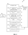
- FIG. 3 shows a block diagram of a data analytics application development system 300, according to an example embodiment.
- Data analytics application development system 300 is an example of development portal 102 of FIG. 1 .
- data analytics application development system 300 includes a development tool 302 and a user interface 304 generated by development tool 302.
- Development tool 302 includes an application information editor 306, a payload definition editor 308, a reference data definition editor 310, a query definition editor 312, a control flow editor 314, a dashboard UI assembly receiver 328, and a package generator 330.
- Flowchart 200 and data analytics application development system 300 are described as follows. Note that not every step of flowchart 200 is performed in every embodiment, and the steps of flowchart 200 may be performed in other orders. Further structural and operational embodiments will be apparent to persons skilled in the relevant art(s) based on the following description.
- Development tool 302 is a tool that a developer may interact with to generate a deployable package for a data analytics application, such as application definition package 108.
- Development tool 302 may be implemented in various ways. For instance, development tool 302 may be implemented in a computing device that the developer interacts with directly, including in the form of an application such as a desktop application, a mobile app, or a Web app. Alternatively, development tool 302 may be implemented in a remote computing device (e.g., a server) that transmits user interface 304 to a computing device of the developer in the form of a web page, and the web page is displayed to the developer in a web browser.
- a remote computing device e.g., a server
- Examples of a suitable computing device include a stationary computer (e.g., a personal computer, a server, etc.) or a mobile computing device such as a handheld device (e.g., a Palm ® device, a RIM Blackberry ® device, a personal digital assistant (PDA)), a laptop computer, a notebook computer, a tablet computer (e.g., an Apple iPad TM , a Microsoft Surface TM , etc.), a netbook, a mobile phone (e.g., a smart phone such as an Apple iPhone, a Google Android TM phone, a Microsoft Windows ® phone, etc.), or other type of computing device.
- Examples of web browsers include Internet Explorer ® , developed by Microsoft Corp. of Redmond, Washington, Mozilla Firefox ® , developed by Mozilla Corp. of Mountain View, California, and Google ® Chrome of Mountain View, California.
- User interface 304 may have any number and combination of user interface elements that may be interacted with by a developer.
- user interface 304 may be a graphical user interface (GUI) that includes one or more graphical user interface controls (e.g., text entry boxes, pull down menus, radio buttons, check boxes, etc.).
- GUI graphical user interface
- User interface 304 may be interacted with by a user in any manner, such as by a keyboard, a thumb wheel, a pointing device, a roller ball, a stick pointer, a touch sensitive display (e.g., by using gesture input), a voice recognition system, and/or other user interface elements described elsewhere herein or otherwise known.
- step 202 a user is enabled to provide a name for the real-time data analytics application.
- application information editor 306 may generate a user interface control that enables a developer to provide a name for a real-time data analytics application being developed by the developer. For instance, the developer may type in the application name, may speak the application name, or provide the application name in another manner to user interface 304, to have the application name received by application information editor 306.
- Application information editor 306 may output the application name in application information 316 in any form, including as a file (e.g., a text file, an XML file, etc.).
- a user may be enabled to provide further application information in this manner.
- the user may be able to interact with a user interface control generated by application information editor 306 to configure security characteristics for the real-time data analytics application, such as being enabled to configure an authentication type or an authorization policy.
- the authentication type may be used by an authentication module to authenticate users and/or devices that attempt to communicate with the real-time data analytics application over a network. Examples of authentication types include passwords, Kerberos, public key encryption, etc.
- the authorization policy may be used by an authorization module to provide access control for purposes of information security, to control users and/or devices that can interact with a particular resource of the real-time data analytics application over a network (e.g., to define access rights, such as read, write, and execute rights). Examples of authorization policies include the use of access control lists, capability-based security, etc.
- Application information editor 306 may indicate the security characteristics in application information 316.
- the user is enabled to provide at least one payload definition that defines real-time data to be received by the real-time data analytics application.
- payload definition editor 308 may generate a user interface control that enables a developer to provide one or more payload definitions.
- a payload definition defines a format of real-time data received from one or more real-time data collection entities. "Real-time data" refers to data that is delivered for processing as soon as it is collected/generated, and typically is data that changes over time.
- a payload definition may define an identifier for a data structure or object received as real-time data, one or more data fields/properties of the identified data structure, and/or one or more further aspects of received real-time data.
- Payload definition editor 308 may output the one or more payload definitions in payload definition(s) 318 in any form, including as a file (e.g., a text file, an XML file, etc.).
- an example payload definition may be provided for real-time data representative of the travel of city buses along their routes within a city.
- Such a payload definition may be identified as "bus travel data" and may include one or more fields such as a bus identifier, a bus location (e.g., coordinates), a bus velocity, a bus travel direction, and a timestamp.
- reference data definition editor 310 may generate a user interface control that enables a developer to provide one or more reference data definitions.
- a reference data definition defines a format of reference data received from a reference data source. "Reference data” refers to fixed data associated with a real-time data analytics application.
- a reference data definition may define an identifier for a data structure or object for reference data, one or more data fields/properties of the identified data structure, and/or one or more further aspects of reference data.
- reference data definition editor 310 may output the one or more reference data definitions in reference definition(s) 320 in any form, including as a file (e.g., a text file, an XML file, etc.).
- an example reference data definition may be provided for locations of bus stops, which are fixed locations.
- Such a reference data definition may be identified as "bus stop location data" and may include one or more fields such as a bus stop identifier, and a bus stop location (e.g., coordinates).
- the user is enabled to provide at least one query definition configured to operate on the real-time data and the reference data to generate output data for the real-time data analytics application.
- query definition editor 312 may generate a user interface control that enables a developer to provide one or more query definitions.
- a query definition defines data analytics logic to be performed on real-time data (defined according to one or more payload definitions) and optionally on reference data (defined according to one or more reference data definitions) to generate output data for a real-time data analytics application.
- a query definition may be formatted in any suitable manner, including as a formula or equation, in the form of a computer program (e.g., XML, JavaScript, C++, etc.), or in another manner.
- an example query definition may be provided for to determine the number of buses traveling over 50 Km/hr within a 1 minute time range.
- a query definition may be provided to determine which buses are within 1 minute of reaching a bus stop at a particular time.
- control flow editor 314 may generate a user interface control that enables a developer to provide one or more control flows (also referred to as workflows).
- a control flow defines control logic to be performed to control the flow of output data from the real-time data analytics application.
- a control flow may synchronize the providing of output data and/or may define other control related functions.
- a control flow may be formatted in any suitable manner, including in the form of a table, as a computer program, or in another manner.
- Control flow editor 314 may output the one or more control flows in control flow definition(s) 324 in any form, including as a file (e.g., a text file, an XML file, etc.).
- dashboard UI assembly receiver 328 may generate a user interface control that enables a developer to provide one or more dashboard UI assemblies.
- a dashboard UI assembly defines a user interface output display element that can be displayed in a user dashboard (e.g., in a web page or other user interface) for providing the output data of the real-time data analytics application to users (e.g., to customers).
- an example first dashboard UI assembly of a table showing lists of buses determined to be traveling over 50 Km/hr and buses within 1 minute of reaching a bus stop and a second dashboard UI assembly that is a city map showing locations of bus stops in the city, and locations of the buses listed in the table.
- dashboard UI assembly receiver 328 may generate a user interface control that enables a developer to provide an application icon that may be used to identify the real-time data analytics application in a list of such applications, and to provide further types of dashboard UI assemblies.
- an application definition package is generated that is configured to enable instances of the real-time data analytics application to be deployed.
- package generator 330 may be configured to generate application definition package 108 to include the generated components for the data analytics application.
- package generator 330 may include one or more of application information 316, payload definition(s) 318, reference data definition(s) 320, query definition(s) 322, control flow definition(s) 324, and dashboard UI assemblies 326.
- Package generator 330 may generate application definition package 108 in various ways, including as a single file that is compressed (e.g., a .ZIP file) or is not compressed, as a folder containing multiple files, etc.
- package generator 330 may generate an application manifest file that lists the components included in application definition package 108, and may include the application manifest file in application definition package 108.
- management portal 104 may be interacted with by a user to create an instance of the data analytics application defined by data analytics application package 108. For instance, as shown in FIG. 1 , management portal 104 may deploy data analytics application package 108 at service 106 to create a data analytics application 110 that is hosted by service 106. Management portal 104 may be configured in various ways, and may perform its functions in various ways.
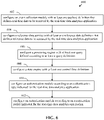
- FIG. 4 shows a flowchart 400 providing a process for deploying a data analytics application based on a deployable data analytics application package, according to an example embodiment.
- flowchart 400 may be performed by management portal 104.
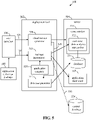
- FIG. 5 shows a block diagram of a data analytics application management system 500, according to an example embodiment.
- Data analytics application management system 500 is an example of management portal 104 of FIG. 1 .
- data analytics application management system 500 includes a deployment tool 502, a server 504, and a user interface 506 generated by deployment tool 502.
- Deployment tool 502 includes a cloud service generator 508, a package instantiator 510, and a database generator 512.
- Server 504 includes a cloud service 514, which is an example of service 106 in FIG. 1 .
- Flowchart 400 and data analytics application management system 500 are described as follows. Note that not every step of flowchart 400 is performed in every embodiment, and the steps of flowchart 400 may be performed in other orders. Further structural and operational embodiments will be apparent to persons skilled in the relevant art(s) based on the following description.
- Deployment tool 502 is a tool that a user (e.g., a customer, etc.) may interact with to generate a data analytics application based on a deployable data analytics application package, such as application definition package 108.
- Deployment tool 502 may be implemented in various ways, including in a similar fashion as development tool 302 of FIG. 3 (e.g., as an application in a remote or local computing device).
- user interface 506 may be implemented similarly to user interface 304 of FIG. 3 (e.g., as a user interface of a local application, a web page displayed in a browser, etc.).
- User interface 506 may be configured in any manner, and may have any number and combination of user interface controls that may be interacted with by a user, including the user interface configurations and controls described above and those that are otherwise known.
- step 402 a selection is received of an application definition package that defines the real-time data analytics application.
- a user may interact with user interface 506 (e.g., a customer dashboard) to select application definition package 108 for deployment as a network-based real-time data analytics service.
- package 108 may be selected from a list of packages displayed in user interface 506.
- an application icon and/or an application name may be displayed in user interface 506 to identify package 108 for selection (in a list of other application names and/or application icons).
- application definition package 108 may be loaded by deployment tool 502 (e.g., into memory).
- deployment tool 502 may verify package 108. For instance, the contents of package 108 may be analyzed to determine whether all components are present (e.g., as indicated by an application manifest, etc.), and each component may be analyzed to determine whether it is valid. For instance, header information may be analyzed, error checking may be performed, and/or further verification processes may be performed.
- a domain name is received for the real-time data analytics application.
- a user may interact with user interface 506 to input a domain name for the network-based real-time data analytics service that is being deployed.
- the user may type in the domain name, may speak the domain name, or provide the domain name in another manner to user interface 506, to have the domain name received by cloud service generator 508.
- a network-based service associated with the domain name is generated.
- cloud (network-based) service generator 508 may generate a cloud service 514 (a network-based service) that is hosted by server 504.
- Cloud service 514 may be hosted at server 504 to be accessible at the domain name provided by the user (in step 404).
- Cloud service 514 is configured to provide the real-time data analytics application as a service over a network.
- the network may be a local area network (LAN), a wide area network (WAN), or a combination of networks, such as the Internet.
- Cloud service 514 may host a website that includes at least one web page (an application dashboard) that enables users to access output data from the real-time data analytics application using a web browser, a mobile, or other application. Furthermore, cloud service 514 may host a web page that is a back-end monitoring console for monitoring the health and/or other activity of the real-time data analytics application. Still further, cloud service 514 may host an address to which real-time data may be transmitted to be used by the real-time data analytics application.
- an application dashboard an application dashboard
- the application definition package is applied to an application template to generate a finalized real-time data analytics package.
- package instantiator 510 receives application definition package 108.
- package instantiator 510 may un-package package 108, and optionally apply the components of package 108 to an application template to generate a finalized real-time data analytics package.
- an application template may be present that includes fillable blanks, fillable program code portions, configurable parameters, and/or other fillable or configurable portions that may be filled and/or configured by the components of a real-time data analytics application package to generate a corresponding fully-configured, end-to-end real-time data analytics service. In this manner, any number of different types of real-time data analytics services/applications may be generated by filling in a generic application template with application-specific information from a data analytics application package.
- FIG. 5 shows an application template 520 that may be received by package instantiator 510.
- Package instantiator 510 may configure application template 520 according to data analytics application package 108 to generate a finalized data analytics application package for deployment to cloud service 514.
- Application template 520 includes one or more of the following configurable data analytics application portions, including a data analytics engine, an application monitor, an authentication module, an authorization module, an event collector, a reference data service, a state engine, and a user dashboard. These portions of application template 520 are further described in the next subsection.
- step 410 the finalized real-time data analytics package is instantiated to the network-based service.
- package instantiator 510 deploys a real-time analytics application 522 at cloud service 514 based on application definition package 108.
- cloud service 514 provides real-time data analytics application 522 as a service over a network, including hosting web pages for real-time data analytics application 522 at the associated domain name, as described above. Further detail on the deployment of a real-time analytics application at a cloud service is described in the following subsection.
- a database is generated for storage of output data from the real-time data analytics application.
- cloud service generator 508 may provide a generate database instruction 528 to database generator 512.
- database generator 512 generates a database 516, which is coupled to real-time data analytics application 522.
- Database 516 is configured to receive, store, and organize data associated with real-time data analytics application 522, including output data generated thereby.
- Database 516 may be an SQL (structured query language)-based database, or other type of database 516, as would be known to persons skilled in the relevant art(s).
- step 414 at least one user interface assembly included in the application definition package is deployed to a network-accessible user dashboard generated for the real-time data analytics application.
- package 108 may include one or more dashboard UI assemblies for a user dashboard.
- package instantiator 510 may unpack and provide the one or more dashboard UI assemblies to server 504 to be included in an application dashboard 518.
- Application dashboard 518 includes one or more network-accessible web pages hosted by cloud service 514 at the network address assigned by cloud service generator 508 (e.g., http://foo.cloudapp.net) as described above.
- the one or more dashboard UI assemblies may be included in the one or more web pages for display to users (e.g., at clients) to enable and/or enhance the display of output data.
- the one or more dashboard UI assemblies may be arranged according to a application dashboard page definition, when present.
- the real-time data analytics application is registered with a central database.
- package instantiator 510 may generate a registration request 530 that is transmitted to a central database 524.
- Central database 524 may be associated with server 504 or may be located at another computing device.
- Registration request 530 causes central database 524 to indicate real-time data analytics application 522 in a list of active data analytics applications maintained thereby.
- an indication of whether real-time data analytics application 522 is running or is stopped, and/or further status information regarding real-time data analytics application 522 may be indicated in central database 524.
- a user may interact with user interface 506 to perform one or more functions, such as starting real-time data analytics application 522, stopping real-time data analytics application 522, removing real-time data analytics application 522, etc.
- an instance of a data analytics application may be generated deployment tool 502 of FIG. 4 by applying a data analytics application package to an application template, and instantiating the results to a cloud service.
- step 602 an event collection module is configured with at least one payload definition that defines real-time data to be received by the real-time data analytics application.
- Package instantiator 510 configures an event collection module of application template 520 with one or more payload definitions (e.g., payload definition(s) 318 of FIG. 3 ) received in package 108.
- the event collection module is configured to receive real-time data.
- the event collection module is capable of receiving real-time data configured according to the one or more payload definitions.
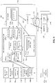
- FIG. 7 shows a block diagram of an application template 700 that can be configured by a data analytics application package to operate as a data analytics service, according to an example embodiment.
- FIG. 7 shows a graphical representation of application template 700, which may actually be implemented in the form of program code (e.g., XML code, JavaScript code, C++ code, etc.).
- application template 700 includes a data analytics processing engine 702, an application monitor 704, an authentication module 706, an authorization module 708, an event collector 710, a reference data service 712, a state engine 714, and a user dashboard 716.
- Application template 700 may be populated by components of an application definition package, and hosted in a cloud service, to generate a real-time data analytics service.
- Event collector 710 of FIG. 7 is configured to receive real-time data.
- event collector 710 When configured by package instantiator 510, event collector 710 is capable of receiving real-time data configured according to the one or more payload definitions.
- FIG. 8 shows a block diagram of application template 700 of FIG. 7 configured according to a data analytics application package to implement a full data analytics application service 800, according to an example embodiment.
- event collector 710 is configured with a first payload definition 802a and a second payload definition 802b.
- First and second payload definitions 802a and 802b define first and second types of real-time data that can be received by event collector 710 (during operation of service 800), as described further above.
- event collector 710 may be configured with any number of payload definitions, corresponding to the number of different types of real-time data to be received.
- event collector 710 receives real-time data 818 that is generated and/or collected by one or more data sources 828a-828n.
- Data sources 828a-828n may include one or more stationary devices, mobile devices, etc, that include sensors of any suitable type.
- Data sources 828a-828n collect and/or generate real-time data, and provide real-time data 818 to event collector 710 in a wired and/or wireless fashion.
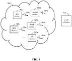
- FIG. 9 shows a block diagram of a data acquisition network 900 that provides data to event collector 710 of a cloud-based data analytics service, according to an example embodiment.
- Data acquisition network 900 is an example of a network of data acquisition devices provided for purposes of illustration.
- data acquisition network 900 includes first-nth devices 902a-902n.
- First-nth devices 902a-902n are examples of data source(s) 828a-828n in FIG. 8 .
- Each of devices 902a-902n is configured to collect (e.g., sense) data and/or to generate real-time data.
- Examples of devices 902a-902n include stationary devices and mobile devices that may each include one or more sensors, processors or other logic, and/or other features for collecting and/or generating data. For instance, sensors may measure speed, temperature, pressure, orientation, amounts of data transmitted, and/or any further parameters that may be expressed as data. Devices 902a-902n may be capable of transmitting such data as real-time data 904a-904n, respectively, in a wireless or wired manner. Any type of real-time data may be generated and/or collected. Event collector 710 may receive real-time data 904a-904n in any manner. In FIG. 8 , real-time data 904a-904n includes real-time data formatted according to first payload definition 804a and according to second payload definition 804b.
- devices 902a-902n may be location, velocity, and orientation sensors carried on city buses.
- Real-time data 904a-904n may include the real-time data collected by devices 902a-902n, including a bus location, a bus velocity, a bus travel direction, and a timestamp, as well as including a bus identifier.
- a reference data service is configured with at least one reference data definition that defines reference data to be accessed by the real-time data analytics application.
- Package instantiator 510 configures a reference data service of application template 520 with one or more reference data definitions (e.g., reference data definition(s) 320 of FIG. 3 ) received in package 108.
- reference data service 712 of application template 700 in FIG. 7 may be configured by package instantiator 510 with reference data definitions 812a-812n, as shown in FIG. 8 .
- reference data service 712 When configured by package instantiator 510, reference data service 712 is capable of receiving and/or maintaining reference data (e.g., stored in a database or other storage) configured according to reference data definitions 812a-812n. During operation of service 800, data analytics processing engine 702 may request reference data from reference data service 712 for use in processing queries.
- reference data e.g., stored in a database or other storage
- a processing engine is configured with at least one query defined according to at least a query definition.
- Package instantiator 510 configures data analytics processing logic of application template 520 with one or more query definitions (e.g., query definition(s) 322 of FIG. 3 ) received in package 108.
- query definitions e.g., query definition(s) 322 of FIG. 3
- data analytics processing engine 702 of application template 700 in FIG. 7 may be configured by package instantiator 510 with queries 808a-808c (based on corresponding query definitions), as shown in FIG. 8 .
- data analytics processing engine 702 When configured by package instantiator 510, data analytics processing engine 702 is capable of receiving reference data 832 from reference data service 712 (formatted according to reference data definitions 812a-812n) and real-time data 820a and 820b from event collector 710 (formatted according to payload definitions 802a and 802b). During operation of service 800, data analytics processing engine 702 executes queries 808a-808c, which each use real-time data 820a and 802b and/or reference data 812a-812n, to generate output data 810a-810c.
- state engine 714 When configured by package instantiator 510, state engine 714 is capable of synchronizing output data 810a-810c at user dashboard 716 as synchronized output data 824 according to control flows 814a-814n. In this manner, various output data generated by processing engine 702 for a particular time value may be provided for display together (e.g., in a common table row, in a map together, etc.) at user dashboard 716. Furthermore, state engine 714 provides a reference data control signal 822 to reference data service 832 to control the timing of reference data provided to data analytics processing engine 702 according to control flows 814a-814n.
- one or more clients 830 may access user dashboard 716 for synchronized output data 824.
- Client(s) 830 may receive synchronized output data 824 from user dashboard 716 in a web page or other form, as output data 816a and 816b.
- Output data 816a and 816b may be received by client(s) 830 through a network 834 (e.g., a LAN, a WAN, a combination of networks such as the Internet, etc.).
- a network 834 e.g., a LAN, a WAN, a combination of networks such as the Internet, etc.
- output data 816a and 816b may be displayed in the web page according to one or more dashboard UI assemblies provided in package 108, in one or more tables (displayed by a table viewer), or in another form.
- an authentication module is configured according to an authentication type indicated for the real-time data analytics application.
- package instantiator 510 may configure an authentication module of application template 520 with an authentication type received in package 108 (e.g., in application information 316).
- authentication module 706 of application template 700 in FIG. 7 may be configured by package instantiator 510 with the authentication type.
- the authentication type may be used by authentication module 706 to authenticate client(s) 830 that attempt to communicate with service 800 over network 834. Examples of authentication types include passwords, Kerberos, public key encryption, etc.
- an authorization module is configured according to an authorization policy indicated for the real-time data analytics application.
- package instantiator 510 may configure an authorization module of application template 520 with an authorization policy received in package 108 (e.g., in application information 316).
- authorization module 708 of application template 700 in FIG. 7 may be configured by package instantiator 510 with the authorization policy.
- the authorization policy may be used by authorization module 706 to provide access control for purposes of information security, to control client(s) 830 that can receive output data. Examples of authorization policies include the use of access control lists, capability-based security, etc.
- Development portal 102, management portal 104, service 106, data analytics application 110, development tool 302, application information editor 306, payload definition editor 308, reference data definition editor 310, query definition editor 312, control flow editor 314, dashboard UI assembly receiver 328, package generator 330, deployment tool 502, cloud service generator 508, package instantiator 510, database generator 512, cloud service 514, real-time data analytics application 522, data analytics processing engine 702, application monitor 704, authentication module 706, authorization module 708, event collector 710, reference data service 712, state engine 714, user dashboard 716, flowchart 200, flowchart 400, and flowchart 600 may be implemented in hardware, or hardware and any combination of software and/or firmware.
- development portal 102, management portal 104, service 106, data analytics application 110, development tool 302, application information editor 306, payload definition editor 308, reference data definition editor 310, query definition editor 312, control flow editor 314, dashboard UI assembly receiver 328, package generator 330, deployment tool 502, cloud service generator 508, package instantiator 510, database generator 512, cloud service 514, real-time data analytics application 522, data analytics processing engine 702, application monitor 704, authentication module 706, authorization module 708, event collector 710, reference data service 712, state engine 714, user dashboard 716, flowchart 200, flowchart 400, and/or flowchart 600 may be implemented as computer program code configured to be executed in one or more processors and stored in a computer readable storage medium.
- development portal 102, management portal 104, service 106, data analytics application 110, development tool 302, application information editor 306, payload definition editor 308, reference data definition editor 310, query definition editor 312, control flow editor 314, dashboard UI assembly receiver 328, package generator 330, deployment tool 502, cloud service generator 508, package instantiator 510, database generator 512, cloud service 514, real-time data analytics application 522, data analytics processing engine 702, application monitor 704, authentication module 706, authorization module 708, event collector 710, reference data service 712, state engine 714, user dashboard 716, flowchart 200, flowchart 400, and/or flowchart 600 may be implemented as hardware logic/electrical circuitry.
- one or more of development portal 102, management portal 104, service 106, data analytics application 110, development tool 302, application information editor 306, payload definition editor 308, reference data definition editor 310, query definition editor 312, control flow editor 314, dashboard UI assembly receiver 328, package generator 330, deployment tool 502, cloud service generator 508, package instantiator 510, database generator 512, cloud service 514, real-time data analytics application 522, data analytics processing engine 702, application monitor 704, authentication module 706, authorization module 708, event collector 710, reference data service 712, state engine 714, user dashboard 716, flowchart 200, flowchart 400, and/or flowchart 600 may be implemented together in a system-on-chip (SoC).
- SoC system-on-chip
- the SoC may include an integrated circuit chip that includes one or more of a processor (e.g., a microcontroller, microprocessor, digital signal processor (DSP), etc.), memory, one or more communication interfaces, and/or further circuits and/or embedded firmware to perform its functions.
- a processor e.g., a microcontroller, microprocessor, digital signal processor (DSP), etc.
- FIG. 10 depicts an exemplary implementation of a computer 1000 in which embodiments of the present invention may be implemented.
- deployment portal 102, management portal 104, service 106, development system 300, deployment tool 502, and/or server 504 may be implemented in one or more computer systems similar to computer 1000, including one or more features of computer 1000 and/or alternative features.
- the description of computer 1000 provided herein is provided for purposes of illustration, and is not intended to be limiting. Embodiments of the present invention may be implemented in further types of computer systems, as would be known to persons skilled in the relevant art(s).
- computer 1000 includes one or more processors 1002, a system memory 1004, and a bus 1006 that couples various system components including system memory 1004 to processor 1002.
- Bus 1006 represents one or more of any of several types of bus structures, including a memory bus or memory controller, a peripheral bus, an accelerated graphics port, and a processor or local bus using any of a variety of bus architectures.
- System memory 1004 includes read only memory (ROM) 1008 and random access memory (RAM) 1010.
- ROM read only memory
- RAM random access memory
- BIOS basic input/output system 1012
- Computer 1000 also has one or more of the following drives: a hard disk drive 1014 for reading from and writing to a hard disk, a magnetic disk drive 1016 for reading from or writing to a removable magnetic disk 1018, and an optical disk drive 1020 for reading from or writing to a removable optical disk 1022 such as a CD ROM, DVD ROM, or other optical media.
- Hard disk drive 1014, magnetic disk drive 1016, and optical disk drive 1020 are connected to bus 1006 by a hard disk drive interface 1024, a magnetic disk drive interface 1026, and an optical drive interface 1028, respectively.
- the drives and their associated computer-readable media provide nonvolatile storage of computer-readable instructions, data structures, program modules and other data for the computer.
- a hard disk, a removable magnetic disk and a removable optical disk are described, other types of computer-readable storage media can be used to store data, such as flash memory cards, digital video disks, random access memories (RAMs), read only memories (ROM), and the like.
- a number of program modules may be stored on the hard disk, magnetic disk, optical disk, ROM, or RAM. These programs include an operating system 1030, one or more application programs 1032, other program modules 1034, and program data 1036.
- Application programs 1032 or program modules 1034 may include, for example, computer program logic (e.g., computer program code or instructions) for implementing development portal 102, management portal 104, service 106, data analytics application 110, development tool 302, application information editor 306, payload definition editor 308, reference data definition editor 310, query definition editor 312, control flow editor 314, dashboard UI assembly receiver 328, package generator 330, deployment tool 502, cloud service generator 508, package instantiator 510, database generator 512, cloud service 514, real-time data analytics application 522, data analytics processing engine 702, application monitor 704, authentication module 706, authorization module 708, event collector 710, reference data service 712, state engine 714, user dashboard 716, flowchart 200, flowchart 400, and/or flowchart 600 (including any step of flowcharts 200
- a user may enter commands and information into the computer 1000 through input devices such as keyboard 1038 and pointing device 1040.
- Other input devices may include a microphone, joystick, game pad, satellite dish, scanner, a touch screen and/or touch pad, a voice recognition system to receive voice input, a gesture recognition system to receive gesture input, or the like.
- processor 1002 may be connected to processor 1002 through a serial port interface 1042 that is coupled to bus 1006, but may be connected by other interfaces, such as a parallel port, game port, or a universal serial bus (USB).
- serial port interface 1042 is coupled to bus 1006, but may be connected by other interfaces, such as a parallel port, game port, or a universal serial bus (USB).
- a display component 1044 is also connected to bus 1006 via an interface, such as a video adapter 1046.
- computer 1000 may include other peripheral output devices (not shown) such as speakers and printers.
- computer program medium As used herein, the terms “computer program medium,” “computer-readable medium,” and “computer-readable storage medium” are used to generally refer to media such as the hard disk associated with hard disk drive 1014, removable magnetic disk 1018, removable optical disk 1022, as well as other media such as flash memory cards, digital video disks, random access memories (RAMs), read only memories (ROM), and the like.
- Such computer-readable storage media are distinguished from and non-overlapping with communication media (do not include communication media).
- Communication media typically embodies computer-readable instructions, data structures, program modules or other data in a modulated data signal such as a carrier wave.
- modulated data signal means a signal that has one or more of its characteristics set or changed in such a manner as to encode information in the signal.
- communication media includes wireless media such as acoustic, RF, infrared and other wireless media. Embodiments are also directed to such communication media.
- computer programs and modules may be stored on the hard disk, magnetic disk, optical disk, ROM, or RAM. Such computer programs may also be received via network interface 1050, serial port interface 1042, or any other interface type. Such computer programs, when executed or loaded by an application, enable computer 1000 to implement features of embodiments of the present invention discussed herein. Accordingly, such computer programs represent controllers of the computer 1000.
- the invention is also directed to computer program products comprising software stored on any computer useable medium.
- Such software when executed in one or more data processing devices, causes a data processing device(s) to operate as described herein.
- Embodiments of the present invention employ any computer-useable or computer-readable medium, known now or in the future. Examples of computer-readable mediums include, but are not limited to storage devices such as RAM, hard drives, floppy disks, CD ROMs, DVD ROMs, zip disks, tapes, magnetic storage devices, optical storage devices, MEMs, nanotechnology-based storage devices, and the like.
Landscapes
- Engineering & Computer Science (AREA)
- Theoretical Computer Science (AREA)
- Software Systems (AREA)
- General Engineering & Computer Science (AREA)
- Physics & Mathematics (AREA)
- General Physics & Mathematics (AREA)
- Computer Security & Cryptography (AREA)
- Computer Hardware Design (AREA)
- Computing Systems (AREA)
- Human Computer Interaction (AREA)
- Debugging And Monitoring (AREA)
- Stored Programmes (AREA)
- Management, Administration, Business Operations System, And Electronic Commerce (AREA)
Description
- "Data analytics" refers to techniques for the analysis of data to draw conclusions about the data. Data analytics is used by many entities, including being used by businesses to make better business decisions, and being used by scientists to verify or disprove existing models or theories. Data analytics is different from data mining. In data mining, data miners sort through huge data sets to identify undiscovered patterns and establish hidden relationships. In contrast, data analytics is directed to deriving conclusions based on the data and the knowledge of the researcher configuring the data analytics. Data analytics may include the inspecting, cleaning, transforming, and modeling of data to highlight useful information, suggest conclusions, support decision making, and/or provide other beneficial results.
- In some cases, data analytics may be performed on "real-time" data, which is data that is delivered for analysis as soon as it is collected or generated. A data analytics application that analyzes real-time data may be referred to as a real-time data analytics application. The development of an end-to-end real-time data analytics application is complicated and labor intensive. A developer of such a real-time data analytics application has to spend a significant amount of time programming the various components of the application, including having to program a data acquisition component, an analytics component, and a results dissemination component.
-
US 2009/288064 A1 discloses techniques for integration of specialized elements into application programs. At a development time, the application program and the specialized elements are bound together using an application program/specialized element interface, which more specifically defines possible ways in which the application program may interact with the specialized elements. -
US 2012/022916 A1 discloses a digital analytics platform, which includes a client profile database, a client identification unit, and an analytics engine. The client profile database is configured to store client profile data. The client identification unit is configured to identify the client profile data corresponding to a first client currently logged into the digital analytics platform. -
US 2010/083287 A1 generally relates to creation of networked or Web applications, and more particularly relates to declarative representations of networked or Web applications. -
US 2011/029963 A1 discloses a system and method for upgrading computer systems. - It is therefore the object of the present invention to provide an improved method for deploying a real-time data analytics application, a corresponding deployment tool configured to deploy the real-time data analytics application, and a corresponding computer program product.
- This object is solved by the subject matter of the independent claims.
- Preferred embodiments are defined by the dependent claims.
- This Summary is provided to introduce a selection of concepts in a simplified form that are further described below in the Detailed Description. This Summary is not intended to identify key features or essential features of the claimed subject matter, nor is it intended to be used to limit the scope of the claimed subject matter.
- Methods, systems, and computer program products are provided for developing an application definition package that contains components used to build a data analytics application. An instance of the data analytics application may be deployed at a network-based service (e.g., a cloud service) by un-packaging the application definition application into a generic framework that provides the data acquisition, data analytics, and results dissemination components. The deployed data analytics application may receive data, including real-time data, and may process the received data to generate output data. The output data may be received and displayed to a user accessing a user dashboard.
- In one implementation, a deployable real-time data analytics application is configured. A user is enabled to provide a name for the real-time data analytics application, to provide at least one payload definition that defines real-time data to be received by the real-time data analytics application, to provide at least one reference data definition that defines reference data to be accessed by the real-time data analytics application, and to provide at least one query definition that defines at least one query configured to operate on the real-time data and the reference data to generate output data for the real-time analytics application. The user may be enabled to configure further components of the real-time data analytics application, including security, control flows, user interface dashboard assemblies, and further components. An application definition package is generated that indicates the application name and includes the payload definition(s), the reference data definition(s), and the query definition(s). The application definition package is configured to be applied to a service framework to enable an instance of the real-time data analytics application to be deployed and be network-accessible.
- In a further implementation, a selection is received of an application definition package that defines a real-time data analytics application. The application definition package indicates an application name and includes at least one payload definition, at least one reference data definition, at least one query definition, and optionally further components. A domain name is provided for the real-time data analytics application, and a network-based service is generated that is associated with the domain name. The application definition package is applied to an application template to generate a finalized real-time data analytics package. The finalized real-time data analytics package is unpackagcd to create an instance of the real-time data analytics application that is deployed to the network-based service.
- In one implementation, a real-time data analytics service includes a data analytics application framework and a network-based service. The data analytics application framework is configurable to generate a real-time data analytics application. The data analytics application framework includes an event collection module, a reference data service, and a data analytics processing engine. The network-based service executes in at least one server and is configured to provide network access for the real-time data analytics application. The event collection module is configured to receive at least one payload definition that defines real-time data to be received by the event collection module. The reference data service is configured to receive at least one reference data definition that defines reference data to be provided by the reference data service. The data analytics processing engine is configured to receive at least a query definition that defines at least one query. The data analytics processing engine is configured to process the real-time data and the reference data according to the query/queries to generate output data for the real-time analytics application.
- Computer program products containing computer readable storage media are also described herein that store computer code/instructions for developing a deployable real-time data analytics application in the form of a package, for deploying such a package to generate a real-time data analytics application, and for operating a deployed instance of a real-time data analytics application, as well as enabling additional embodiments described herein.
- Further features and advantages of the invention, as well as the structure and operation of various embodiments of the invention, are described in detail below with reference to the accompanying drawings. It is noted that the invention is not limited to the specific embodiments described herein. Such embodiments are presented herein for illustrative purposes only. Additional embodiments will be apparent to persons skilled in the relevant art(s) based on the teachings contained herein.
- The accompanying drawings, which are incorporated herein and form a part of the specification, illustrate the present invention and, together with the description, further serve to explain the principles of the invention and to enable a person skilled in the pertinent art to make and use the invention.
-
FIG. 1 shows a block diagram of a data analytics system, according to an example embodiment. -
FIG. 2 shows a flowchart providing a process for enabling a user to develop a deployable data analytics application package, according to an example embodiment. -
FIG. 3 shows a block diagram of a data analytics application development system, according to an example embodiment. -
FIG. 4 shows a flowchart providing a process for deploying a data analytics application based on a deployable data analytics application package, according to an example embodiment. -
FIG. 5 shows a block diagram of a data analytics application management system, according to an example embodiment. -
FIG. 6 shows a flowchart providing a process for operating a data analytics application deployed as a service from a data analytics application package, according to an example embodiment. -
FIG. 7 shows a block diagram of an application template that can be configured by a data analytics application package to operate as a data analytics service, according to an example embodiment. -
FIG. 8 shows a block diagram of the application template ofFIG. 7 configured according to a data analytics application package to implement a full data analytics service, according to an example embodiment. -
FIG. 9 shows a block diagram of a data acquisition network that provides data to an event collector of a cloud-based data analytics service, according to an example embodiment. -
FIG. 10 shows a block diagram of an example computer that may be used to implement embodiments of the present invention. - The features and advantages of the present invention will become more apparent from the detailed description set forth below when taken in conjunction with the drawings, in which like reference characters identify corresponding elements throughout. In the drawings, like reference numbers generally indicate identical, functionally similar, and/or structurally similar elements. The drawing in which an element first appears is indicated by the leftmost digit(s) in the corresponding reference number.
- The invention is defined by the claims appended hereto.
- References in the specification to "one embodiment," "an embodiment," "an example embodiment," etc., indicate that the embodiment described may include a particular feature, structure, or characteristic, but every embodiment may not necessarily include the particular feature, structure, or characteristic. Moreover, such phrases are not necessarily referring to the same embodiment. Further, when a particular feature, structure, or characteristic is described in connection with an embodiment, it is submitted that it is within the knowledge of one skilled in the art to effect such feature, structure, or characteristic in connection with other embodiments whether or not explicitly described.
- Numerous exemplary embodiments of the present invention are described as follows. It is noted that any section/subsection headings provided herein are not intended to be limiting. Embodiments are described throughout this document, and any type of embodiment may be included under any section/subsection. Furthermore, embodiments disclosed in any section/subsection may be combined with any other embodiments described in the same section/subsection and/or a different section/subsection in any manner.
- "Data analytics" refers to techniques for the analysis of data to draw conclusions about the data, and is used by many entities to make improved business decisions, to verify or disprove existing models or theories, and for further reasons. Data analytics may include the inspecting, cleaning, transforming, and modeling of data to highlight useful information, suggest conclusions, support decision making, and/or provide other beneficial results. In some cases, data analytics may be performed on "real-time" data, which is data that is delivered for analysis as soon as it is collected or generated. Such real-time data may be received continually, and may be analyzed at any time to make conclusions about the applicable environment at the collection time.
- A data analytics application that analyzes real-time data may be referred to as a real-time analytics application. A real-time data analytics application that is deployed to a network-based service (e.g., a cloud service) may be referred to as a real-time data analytics service. The development of an end-to-end real-time data analytics service is complicated and labor intensive. A developer of such a real-time data analytics service has to spend a significant amount of time programming the various components of the service, including having to program a data acquisition component, an analytics component, and a results dissemination component for the service.
- According to embodiments, a data analytics framework or system is provided that enables data analytics applications to be developed in a more efficient manner. For instance, in an embodiment, a data analytics development portal may be used to develop a data analytics application in a deployable form, such as a package. A management portal may receive the package, and based on the package may deploy an instance of the data analytics application in the data analytics framework as a service. The data analytics framework provides an interface for data collection, an analytics engine for performing the data analytics, and an interface for outputting information to one or more clients. The framework is configured according to the package to operate as a data analytics service for the data analytics application.
- For instance, in an embodiment, a meta-data driven real-time analytic framework is provided. The framework utilizes a deployment container for an end-to-end real-time analytics solution, and a real-time analytics service host. A developer may make use of a design tool used to model the end-to-end analytics solution. The analytics model includes various components configured by the developer such as ingress event acquisition endpoints, an ingress event payload definition, a result payload definition, reference data, a control-flow, and configurations. The analytics model may be encapsulated into a deployment container that is a single deployment file (e.g., an ".adpac" file), which can be provided to a network location (e.g., to the "cloud").
- The real-time analytics service host may receive the analytics model in the deployment file, and may deploy the analytics model by physically instantiating the different components included in the deployment file. The host may automatically connect the different components together, and the user may configure and startup the resulting data analytics solution as a real-time data analytics service. The real-time analytic service host may be configured to monitor the health of the real-time data analytics service.
- As such, according to embodiments, a developer can define the core components of a data analytics service, such as a structure of the input data, a structure of any reference data, and the analytics logic (e.g., in the form of a query) to be performed on the input data and reference data to generate output data, without having to additionally generate a data acquisition component, an analytics component, and a results dissemination component. Instead, the infrastructure or framework for a data acquisition component, an analytics component, and a results dissemination component are provided for the developer. The components provided by the developer are instantiated in the provided framework to create an end-to-end data analytics service.
-
FIG. 1 shows a block diagram of adata analytics system 100, according to an example embodiment. As shown inFIG. 1 ,data analytics system 100 includes adevelopment portal 102, amanagement portal 104, and aservice 106 that is a service for adata analytics application 110.Deployment portal 102 is configured to provide an interface (e.g., a tool, etc.) for a developer to configure and package components of a data analytics application. Examples of the components include an input data definition (or model), a reference data definition (or model), and a data analytics logic definition (e.g., one or more queries).Deployment portal 102 packages the components in a data analytics application package 108 (e.g., a file or other container) that is transportable and may be deployed to create an instance of the data analytics application. - As shown in
FIG. 1 ,management portal 104 may receive dataanalytics application package 108, and may create an instance of the data analytics application defined by dataanalytics application package 108 by unpacking the components contained therein. For instance, as shown inFIG. 1 ,management portal 104 may deploy dataanalytics application package 108 atservice 106 to create adata analytics application 110 that is hosted byservice 106.Service 106 provides a framework fordata analytics application 110, such as an input data interface, a reference data service, a data analytics engine, and an output data interface (e.g., a user or client interface).Service 106 may be a network or cloud-based service so that clients may receive output information fromdata analytics application 110. Any number of instances ofdata analytics application 110 may be deployed at one or more services as data analytics services based on dataanalytics application package 108. - The elements of
data analytics system 100 shown inFIG. 1 may be configured in various ways, in embodiments. Example embodiments fordata analytics system 100 are described in the following subsections. - As described above,
deployment portal 102 is configured to provide an interface for a developer to configure components of a data analytics application, and to generate dataanalytics application package 108, which is a transportable and deployable container to that may be used to generate instances of the data analytics application.Deployment portal 102 may be configured in various ways, and may perform its functions in various ways. - For instance,
FIG. 2 shows aflowchart 200 providing a process for enabling a user to develop a deployable data analytics application package, according to an example embodiment. In an embodiment,flowchart 200 may be performed bydeployment portal 102. For purposes of illustration,flowchart 200 ofFIG. 2 is described with respect toFIG. 3. FIG. 3 shows a block diagram of a data analyticsapplication development system 300, according to an example embodiment. Data analyticsapplication development system 300 is an example ofdevelopment portal 102 ofFIG. 1 . As shown inFIG. 3 , data analyticsapplication development system 300 includes adevelopment tool 302 and auser interface 304 generated bydevelopment tool 302.Development tool 302 includes anapplication information editor 306, apayload definition editor 308, a referencedata definition editor 310, aquery definition editor 312, acontrol flow editor 314, a dashboardUI assembly receiver 328, and apackage generator 330.Flowchart 200 and data analyticsapplication development system 300 are described as follows. Note that not every step offlowchart 200 is performed in every embodiment, and the steps offlowchart 200 may be performed in other orders. Further structural and operational embodiments will be apparent to persons skilled in the relevant art(s) based on the following description. -
Development tool 302 is a tool that a developer may interact with to generate a deployable package for a data analytics application, such asapplication definition package 108.Development tool 302 may be implemented in various ways. For instance,development tool 302 may be implemented in a computing device that the developer interacts with directly, including in the form of an application such as a desktop application, a mobile app, or a Web app. Alternatively,development tool 302 may be implemented in a remote computing device (e.g., a server) that transmitsuser interface 304 to a computing device of the developer in the form of a web page, and the web page is displayed to the developer in a web browser. - Examples of a suitable computing device include a stationary computer (e.g., a personal computer, a server, etc.) or a mobile computing device such as a handheld device (e.g., a Palm® device, a RIM Blackberry® device, a personal digital assistant (PDA)), a laptop computer, a notebook computer, a tablet computer (e.g., an Apple iPad™, a Microsoft Surface™, etc.), a netbook, a mobile phone (e.g., a smart phone such as an Apple iPhone, a Google Android™ phone, a Microsoft Windows® phone, etc.), or other type of computing device. Examples of web browsers include Internet Explorer®, developed by Microsoft Corp. of Redmond, Washington, Mozilla Firefox®, developed by Mozilla Corp. of Mountain View, California, and Google® Chrome of Mountain View, California.
-
User interface 304 may have any number and combination of user interface elements that may be interacted with by a developer. For instance,user interface 304 may be a graphical user interface (GUI) that includes one or more graphical user interface controls (e.g., text entry boxes, pull down menus, radio buttons, check boxes, etc.).User interface 304 may be interacted with by a user in any manner, such as by a keyboard, a thumb wheel, a pointing device, a roller ball, a stick pointer, a touch sensitive display (e.g., by using gesture input), a voice recognition system, and/or other user interface elements described elsewhere herein or otherwise known. - As shown in
FIG. 2 ,flowchart 200 begins withstep 202. Instep 202, a user is enabled to provide a name for the real-time data analytics application. For example, in an embodiment,application information editor 306 may generate a user interface control that enables a developer to provide a name for a real-time data analytics application being developed by the developer. For instance, the developer may type in the application name, may speak the application name, or provide the application name in another manner touser interface 304, to have the application name received byapplication information editor 306.Application information editor 306 may output the application name inapplication information 316 in any form, including as a file (e.g., a text file, an XML file, etc.). - In embodiments, a user may be enabled to provide further application information in this manner. For instance, the user may be able to interact with a user interface control generated by
application information editor 306 to configure security characteristics for the real-time data analytics application, such as being enabled to configure an authentication type or an authorization policy. The authentication type may be used by an authentication module to authenticate users and/or devices that attempt to communicate with the real-time data analytics application over a network. Examples of authentication types include passwords, Kerberos, public key encryption, etc. The authorization policy may be used by an authorization module to provide access control for purposes of information security, to control users and/or devices that can interact with a particular resource of the real-time data analytics application over a network (e.g., to define access rights, such as read, write, and execute rights). Examples of authorization policies include the use of access control lists, capability-based security, etc.Application information editor 306 may indicate the security characteristics inapplication information 316. - In
step 204, the user is enabled to provide at least one payload definition that defines real-time data to be received by the real-time data analytics application. For instance, in an embodiment,payload definition editor 308 may generate a user interface control that enables a developer to provide one or more payload definitions. A payload definition defines a format of real-time data received from one or more real-time data collection entities. "Real-time data" refers to data that is delivered for processing as soon as it is collected/generated, and typically is data that changes over time. For instance, a payload definition may define an identifier for a data structure or object received as real-time data, one or more data fields/properties of the identified data structure, and/or one or more further aspects of received real-time data. As such, the user may type in a payload definition, provide a payload definition by voice, or provide a payload definition in another manner touser interface 304, to have the payload definition received bypayload definition editor 308. Any number of payload definitions may be provided for a particular real-time data analytics application, to define corresponding different types of real-time data to be received.Payload definition editor 308 may output the one or more payload definitions in payload definition(s) 318 in any form, including as a file (e.g., a text file, an XML file, etc.). - For instance, in a city bus transportation data analytics application, an example payload definition may be provided for real-time data representative of the travel of city buses along their routes within a city. Such a payload definition may be identified as "bus travel data" and may include one or more fields such as a bus identifier, a bus location (e.g., coordinates), a bus velocity, a bus travel direction, and a timestamp.
- In
step 206, the user is enabled to provide at least one reference data definition that defines reference data to be used by the real-time data analytics application. For instance, in an embodiment, referencedata definition editor 310 may generate a user interface control that enables a developer to provide one or more reference data definitions. A reference data definition defines a format of reference data received from a reference data source. "Reference data" refers to fixed data associated with a real-time data analytics application. For instance, a reference data definition may define an identifier for a data structure or object for reference data, one or more data fields/properties of the identified data structure, and/or one or more further aspects of reference data. As such, the user may type in a reference data definition, provide a reference data definition by voice, or provide a reference data definition in another manner touser interface 304, to have the reference data definition received by referencedata definition editor 310. Any number of reference data definitions may be provided for a particular real-time data analytics application, to define corresponding different types of reference data to be received. Referencedata definition editor 310 may output the one or more reference data definitions in reference definition(s) 320 in any form, including as a file (e.g., a text file, an XML file, etc.). - For instance, continuing the city bus transportation data analytics application, an example reference data definition may be provided for locations of bus stops, which are fixed locations. Such a reference data definition may be identified as "bus stop location data" and may include one or more fields such as a bus stop identifier, and a bus stop location (e.g., coordinates).
- In
step 208, the user is enabled to provide at least one query definition configured to operate on the real-time data and the reference data to generate output data for the real-time data analytics application. For instance, in an embodiment,query definition editor 312 may generate a user interface control that enables a developer to provide one or more query definitions. A query definition defines data analytics logic to be performed on real-time data (defined according to one or more payload definitions) and optionally on reference data (defined according to one or more reference data definitions) to generate output data for a real-time data analytics application. A query definition may be formatted in any suitable manner, including as a formula or equation, in the form of a computer program (e.g., XML, JavaScript, C++, etc.), or in another manner. As such, the user may type in a query definition, provide a query definition by voice, load a query definition from a document, or provide a query definition in another manner touser interface 304, to have the query definition received byquery definition editor 312.Query definition editor 312 may provide for automatic code completion to assist entry of query definitions, in an embodiment. Any number of query definitions may be provided for a particular real-time data analytics application, to define corresponding queries to be performed.Query definition editor 312 may output the one or more query definitions in query definition(s) 322 in any form, including as a file (e.g., a text file, an XML file, etc.). - For instance, continuing the city bus transportation data analytics application, an example query definition may be provided for to determine the number of buses traveling over 50 Km/hr within a 1 minute time range. In another example, a query definition may be provided to determine which buses are within 1 minute of reaching a bus stop at a particular time.
- In
step 210, the user is enabled to provide at least one control flow definition for the real-time data analytics application. For instance, in an embodiment,control flow editor 314 may generate a user interface control that enables a developer to provide one or more control flows (also referred to as workflows). A control flow defines control logic to be performed to control the flow of output data from the real-time data analytics application. For instance, in an embodiment, a control flow may synchronize the providing of output data and/or may define other control related functions. A control flow may be formatted in any suitable manner, including in the form of a table, as a computer program, or in another manner. As such, the user may type in a control flow, provide a control flow by voice, load a control flow from a document, or provide a control flow in another manner touser interface 304, to have the control flow received bycontrol flow editor 314. Any number of control flows may be provided for a particular real-time data analytics application.Control flow editor 314 may output the one or more control flows in control flow definition(s) 324 in any form, including as a file (e.g., a text file, an XML file, etc.). - For instance, continuing the city bus transportation data analytics application, an example control flow may be provided that synchronizes the output data indicating the determined number of buses traveling over 50 Km/hr and the determined buses that are within 1 minute of reaching a bus stop, to a same 1 minute time span.
- In
step 212, the user is enabled to provide at least one dashboard user interface (UI) assembly for a user dashboard for the real-time data analytics application. For instance, in an embodiment, dashboardUI assembly receiver 328 may generate a user interface control that enables a developer to provide one or more dashboard UI assemblies. A dashboard UI assembly defines a user interface output display element that can be displayed in a user dashboard (e.g., in a web page or other user interface) for providing the output data of the real-time data analytics application to users (e.g., to customers). Any type and number of user interface output display elements may be provided as dashboard UI assemblies, including images, maps, tables, charts, graphs, UI elements defined in program code (e.g., XML, JavaScript, etc.), etc., for displaying output data. An application dashboard page definition may be provided in the form of program code (e.g., XML, HTML, etc.) that defines a layout of the application dashboard, including locations for any provided dashboard UI assemblies. As such, the user may upload or provide dashboard UI assemblies (and application dashboard page definition) in any manner touser interface 304, to be received by dashboardUI assembly receiver 328. Any number of dashboard UI assemblies may be provided for a particular real-time data analytics application. DashboardUI assembly receiver 328 may output the one or more dashboard UI assemblies (and application dashboard page definition) indashboard UI assemblies 326. - For instance, continuing the city bus transportation data analytics application, an example first dashboard UI assembly of a table showing lists of buses determined to be traveling over 50 Km/hr and buses within 1 minute of reaching a bus stop, and a second dashboard UI assembly that is a city map showing locations of bus stops in the city, and locations of the buses listed in the table.
- In another embodiment, dashboard
UI assembly receiver 328 may generate a user interface control that enables a developer to provide an application icon that may be used to identify the real-time data analytics application in a list of such applications, and to provide further types of dashboard UI assemblies. - Referring back to
FIG. 2 , instep 214, an application definition package is generated that is configured to enable instances of the real-time data analytics application to be deployed. For example, in an embodiment,package generator 330 may be configured to generateapplication definition package 108 to include the generated components for the data analytics application. For instance,package generator 330 may include one or more ofapplication information 316, payload definition(s) 318, reference data definition(s) 320, query definition(s) 322, control flow definition(s) 324, anddashboard UI assemblies 326.Package generator 330 may generateapplication definition package 108 in various ways, including as a single file that is compressed (e.g., a .ZIP file) or is not compressed, as a folder containing multiple files, etc. In an embodiment,package generator 330 may generate an application manifest file that lists the components included inapplication definition package 108, and may include the application manifest file inapplication definition package 108. - As described above with respect to
FIG. 1 ,management portal 104 may be interacted with by a user to create an instance of the data analytics application defined by dataanalytics application package 108. For instance, as shown inFIG. 1 ,management portal 104 may deploy dataanalytics application package 108 atservice 106 to create adata analytics application 110 that is hosted byservice 106.Management portal 104 may be configured in various ways, and may perform its functions in various ways. - For instance,
FIG. 4 shows aflowchart 400 providing a process for deploying a data analytics application based on a deployable data analytics application package, according to an example embodiment. In an embodiment,flowchart 400 may be performed bymanagement portal 104. For purposes of illustration,flowchart 400 ofFIG. 4 is described with respect toFIG. 5. FIG. 5 shows a block diagram of a data analyticsapplication management system 500, according to an example embodiment. Data analyticsapplication management system 500 is an example ofmanagement portal 104 ofFIG. 1 . As shown inFIG. 5 , data analyticsapplication management system 500 includes adeployment tool 502, aserver 504, and auser interface 506 generated bydeployment tool 502.Deployment tool 502 includes acloud service generator 508, apackage instantiator 510, and adatabase generator 512.Server 504 includes acloud service 514, which is an example ofservice 106 inFIG. 1 .Flowchart 400 and data analyticsapplication management system 500 are described as follows. Note that not every step offlowchart 400 is performed in every embodiment, and the steps offlowchart 400 may be performed in other orders. Further structural and operational embodiments will be apparent to persons skilled in the relevant art(s) based on the following description. -
Deployment tool 502 is a tool that a user (e.g., a customer, etc.) may interact with to generate a data analytics application based on a deployable data analytics application package, such asapplication definition package 108.Deployment tool 502 may be implemented in various ways, including in a similar fashion asdevelopment tool 302 ofFIG. 3 (e.g., as an application in a remote or local computing device). Similarly,user interface 506 may be implemented similarly touser interface 304 ofFIG. 3 (e.g., as a user interface of a local application, a web page displayed in a browser, etc.).User interface 506 may be configured in any manner, and may have any number and combination of user interface controls that may be interacted with by a user, including the user interface configurations and controls described above and those that are otherwise known. - In
FIG. 4 ,flowchart 400 begins withstep 402. Instep 402, a selection is received of an application definition package that defines the real-time data analytics application. For example, as shown inFIG. 5 , a user may interact with user interface 506 (e.g., a customer dashboard) to selectapplication definition package 108 for deployment as a network-based real-time data analytics service. For instance,package 108 may be selected from a list of packages displayed inuser interface 506. In one embodiment an application icon and/or an application name (as described above) may be displayed inuser interface 506 to identifypackage 108 for selection (in a list of other application names and/or application icons). Upon selection,application definition package 108 may be loaded by deployment tool 502 (e.g., into memory). - In an embodiment, when
package 108 is loaded, deployment tool 502 (e.g., package instantiator 510) may verifypackage 108. For instance, the contents ofpackage 108 may be analyzed to determine whether all components are present (e.g., as indicated by an application manifest, etc.), and each component may be analyzed to determine whether it is valid. For instance, header information may be analyzed, error checking may be performed, and/or further verification processes may be performed. - In
step 404, a domain name is received for the real-time data analytics application. For example, as shown inFIG. 5 , a user may interact withuser interface 506 to input a domain name for the network-based real-time data analytics service that is being deployed. For instance, the user may type in the domain name, may speak the domain name, or provide the domain name in another manner touser interface 506, to have the domain name received bycloud service generator 508. - In
step 406, a network-based service associated with the domain name is generated. For example, in an embodiment, cloud (network-based)service generator 508 may generate a cloud service 514 (a network-based service) that is hosted byserver 504.Cloud service 514 may be hosted atserver 504 to be accessible at the domain name provided by the user (in step 404).Cloud service 514 is configured to provide the real-time data analytics application as a service over a network. The network may be a local area network (LAN), a wide area network (WAN), or a combination of networks, such as the Internet.Cloud service 514 may host a website that includes at least one web page (an application dashboard) that enables users to access output data from the real-time data analytics application using a web browser, a mobile, or other application. Furthermore,cloud service 514 may host a web page that is a back-end monitoring console for monitoring the health and/or other activity of the real-time data analytics application. Still further,cloud service 514 may host an address to which real-time data may be transmitted to be used by the real-time data analytics application. - For instance, in one illustrative example, when a user provides a domain name of "foo" to
user interface 506, in response,cloud service generator 508 may assign the following URLs for the resulting cloud service: - http://foo.cloudapp.net - this is a network address for the application dashboard
- http://foo.cloudapp.net/EventReceiver - this is a network address to which real-time data collection devices send real-data
- http://foo.cloudapp.net/monitor: this is a network address for a back-end monitoring console
- In
step 408, the application definition package is applied to an application template to generate a finalized real-time data analytics package. As shown inFIG. 5 ,package instantiator 510 receivesapplication definition package 108. In an embodiment,package instantiator 510 may un-packagepackage 108, and optionally apply the components ofpackage 108 to an application template to generate a finalized real-time data analytics package. For instance, an application template may be present that includes fillable blanks, fillable program code portions, configurable parameters, and/or other fillable or configurable portions that may be filled and/or configured by the components of a real-time data analytics application package to generate a corresponding fully-configured, end-to-end real-time data analytics service. In this manner, any number of different types of real-time data analytics services/applications may be generated by filling in a generic application template with application-specific information from a data analytics application package. - For instance,
FIG. 5 shows anapplication template 520 that may be received bypackage instantiator 510.Package instantiator 510 may configureapplication template 520 according to dataanalytics application package 108 to generate a finalized data analytics application package for deployment tocloud service 514.Application template 520 includes one or more of the following configurable data analytics application portions, including a data analytics engine, an application monitor, an authentication module, an authorization module, an event collector, a reference data service, a state engine, and a user dashboard. These portions ofapplication template 520 are further described in the next subsection. - In
step 410, the finalized real-time data analytics package is instantiated to the network-based service. As inFIG. 5 ,package instantiator 510 deploys a real-time analytics application 522 atcloud service 514 based onapplication definition package 108. When activated,cloud service 514 provides real-timedata analytics application 522 as a service over a network, including hosting web pages for real-timedata analytics application 522 at the associated domain name, as described above. Further detail on the deployment of a real-time analytics application at a cloud service is described in the following subsection. - In
step 412, a database is generated for storage of output data from the real-time data analytics application. For example, as shown inFIG. 5 ,cloud service generator 508 may provide a generatedatabase instruction 528 todatabase generator 512. In response,database generator 512 generates adatabase 516, which is coupled to real-timedata analytics application 522.Database 516 is configured to receive, store, and organize data associated with real-timedata analytics application 522, including output data generated thereby.Database 516 may be an SQL (structured query language)-based database, or other type ofdatabase 516, as would be known to persons skilled in the relevant art(s). - In
step 414, at least one user interface assembly included in the application definition package is deployed to a network-accessible user dashboard generated for the real-time data analytics application. For example, as described above,package 108 may include one or more dashboard UI assemblies for a user dashboard. In an embodiment,package instantiator 510 may unpack and provide the one or more dashboard UI assemblies toserver 504 to be included in anapplication dashboard 518.Application dashboard 518 includes one or more network-accessible web pages hosted bycloud service 514 at the network address assigned by cloud service generator 508 (e.g., http://foo.cloudapp.net) as described above. The one or more dashboard UI assemblies may be included in the one or more web pages for display to users (e.g., at clients) to enable and/or enhance the display of output data. The one or more dashboard UI assemblies may be arranged according to a application dashboard page definition, when present. - In
step 416, the real-time data analytics application is registered with a central database. For example, as shown inFIG. 5 ,package instantiator 510 may generate aregistration request 530 that is transmitted to acentral database 524.Central database 524 may be associated withserver 504 or may be located at another computing device.Registration request 530 causescentral database 524 to indicate real-timedata analytics application 522 in a list of active data analytics applications maintained thereby. Furthermore, an indication of whether real-timedata analytics application 522 is running or is stopped, and/or further status information regarding real-timedata analytics application 522 may be indicated incentral database 524. - Furthermore, upon instantiating real-time
data analytics application 522, a user may interact withuser interface 506 to perform one or more functions, such as starting real-timedata analytics application 522, stopping real-timedata analytics application 522, removing real-timedata analytics application 522, etc. - As described above with respect to
steps FIG. 4 ), an instance of a data analytics application may be generateddeployment tool 502 ofFIG. 4 by applying a data analytics application package to an application template, and instantiating the results to a cloud service. -
FIG. 6 shows a flowchart providing a process for operating a data analytics application deployed as a service from a data analytics application package, according to an example embodiment. In an embodiment,flowchart 600 may be performed bypackage instantiator 510 ofFIG. 5 .Flowchart 600 is described as follows with respect toFIGS. 7-9 . Note that not every step offlowchart 600 is performed in every embodiment, and the steps offlowchart 600 may be performed in other orders than the order shown inFIG. 6 . Further structural and operational embodiments will be apparent to persons skilled in the relevant art(s) based on the following description. - In
FIG. 6 ,flowchart 600 begins withstep 602. Instep 602, an event collection module is configured with at least one payload definition that defines real-time data to be received by the real-time data analytics application.Package instantiator 510 configures an event collection module ofapplication template 520 with one or more payload definitions (e.g., payload definition(s) 318 ofFIG. 3 ) received inpackage 108. The event collection module is configured to receive real-time data. When configured bypackage instantiator 510, the event collection module is capable of receiving real-time data configured according to the one or more payload definitions. - For instance,
FIG. 7 shows a block diagram of anapplication template 700 that can be configured by a data analytics application package to operate as a data analytics service, according to an example embodiment.FIG. 7 shows a graphical representation ofapplication template 700, which may actually be implemented in the form of program code (e.g., XML code, JavaScript code, C++ code, etc.). As shown inFIG. 7 ,application template 700 includes a dataanalytics processing engine 702, anapplication monitor 704, anauthentication module 706, anauthorization module 708, anevent collector 710, areference data service 712, astate engine 714, and auser dashboard 716. One or more of these features ofapplication template 700 may not be present in some embodiments.Application template 700 may be populated by components of an application definition package, and hosted in a cloud service, to generate a real-time data analytics service. -
Event collector 710 ofFIG. 7 is configured to receive real-time data. When configured bypackage instantiator 510,event collector 710 is capable of receiving real-time data configured according to the one or more payload definitions. For instance,FIG. 8 shows a block diagram ofapplication template 700 ofFIG. 7 configured according to a data analytics application package to implement a full dataanalytics application service 800, according to an example embodiment. As shown inFIG. 8 ,event collector 710 is configured with afirst payload definition 802a and asecond payload definition 802b. First andsecond payload definitions event collector 710 may be configured with any number of payload definitions, corresponding to the number of different types of real-time data to be received. - As shown in
FIG. 8 ,event collector 710 receives real-time data 818 that is generated and/or collected by one ormore data sources 828a-828n.Data sources 828a-828n may include one or more stationary devices, mobile devices, etc, that include sensors of any suitable type.Data sources 828a-828n collect and/or generate real-time data, and provide real-time data 818 toevent collector 710 in a wired and/or wireless fashion. - For instance,
FIG. 9 shows a block diagram of adata acquisition network 900 that provides data toevent collector 710 of a cloud-based data analytics service, according to an example embodiment.Data acquisition network 900 is an example of a network of data acquisition devices provided for purposes of illustration. As shown inFIG. 9 ,data acquisition network 900 includes first-nth devices 902a-902n. First-nth devices 902a-902n are examples of data source(s) 828a-828n inFIG. 8 . Each ofdevices 902a-902n is configured to collect (e.g., sense) data and/or to generate real-time data. Examples ofdevices 902a-902n include stationary devices and mobile devices that may each include one or more sensors, processors or other logic, and/or other features for collecting and/or generating data. For instance, sensors may measure speed, temperature, pressure, orientation, amounts of data transmitted, and/or any further parameters that may be expressed as data.Devices 902a-902n may be capable of transmitting such data as real-time data 904a-904n, respectively, in a wireless or wired manner. Any type of real-time data may be generated and/or collected.Event collector 710 may receive real-time data 904a-904n in any manner. InFIG. 8 , real-time data 904a-904n includes real-time data formatted according to first payload definition 804a and according tosecond payload definition 804b. - For instance, continuing the city bus transportation example,
devices 902a-902n may be location, velocity, and orientation sensors carried on city buses. Real-time data 904a-904n may include the real-time data collected bydevices 902a-902n, including a bus location, a bus velocity, a bus travel direction, and a timestamp, as well as including a bus identifier. - Referring back to
FIG. 6 , instep 604, a reference data service is configured with at least one reference data definition that defines reference data to be accessed by the real-time data analytics application.Package instantiator 510 configures a reference data service ofapplication template 520 with one or more reference data definitions (e.g., reference data definition(s) 320 ofFIG. 3 ) received inpackage 108. For instance,reference data service 712 ofapplication template 700 inFIG. 7 may be configured bypackage instantiator 510 withreference data definitions 812a-812n, as shown inFIG. 8 . When configured bypackage instantiator 510,reference data service 712 is capable of receiving and/or maintaining reference data (e.g., stored in a database or other storage) configured according toreference data definitions 812a-812n. During operation ofservice 800, dataanalytics processing engine 702 may request reference data fromreference data service 712 for use in processing queries. - In
step 606, a processing engine is configured with at least one query defined according to at least a query definition.Package instantiator 510 configures data analytics processing logic ofapplication template 520 with one or more query definitions (e.g., query definition(s) 322 ofFIG. 3 ) received inpackage 108. For instance, dataanalytics processing engine 702 ofapplication template 700 inFIG. 7 may be configured bypackage instantiator 510 withqueries 808a-808c (based on corresponding query definitions), as shown inFIG. 8 . When configured bypackage instantiator 510, dataanalytics processing engine 702 is capable of receivingreference data 832 from reference data service 712 (formatted according toreference data definitions 812a-812n) and real-time data payload definitions service 800, dataanalytics processing engine 702 executesqueries 808a-808c, which each use real-time data reference data 812a-812n, to generateoutput data 810a-810c. - In
step 608, a state engine is configured with at least one control flow definition.Package instantiator 510 configures a state engine ofapplication template 520 with one or more control flow definitions (e.g., control flow definition(s) 324 ofFIG. 3 ) received inpackage 108. For instance,state engine 714 ofapplication template 700 inFIG. 7 may be configured bypackage instantiator 510 withcontrol flows 814a-814n (based on corresponding control flow definitions), as shown inFIG. 8 .State engine 714 is configured to provide a "view of the world" forservice 800, and may interact with dataanalytics processing engine 702,reference data service 712, anduser dashboard 824 to perform its functions. When configured bypackage instantiator 510,state engine 714 is capable of synchronizingoutput data 810a-810c atuser dashboard 716 assynchronized output data 824 according tocontrol flows 814a-814n. In this manner, various output data generated by processingengine 702 for a particular time value may be provided for display together (e.g., in a common table row, in a map together, etc.) atuser dashboard 716. Furthermore,state engine 714 provides a referencedata control signal 822 toreference data service 832 to control the timing of reference data provided to dataanalytics processing engine 702 according tocontrol flows 814a-814n. - During operation of
service 800, one ormore clients 830 may accessuser dashboard 716 forsynchronized output data 824. Client(s) 830 may receivesynchronized output data 824 fromuser dashboard 716 in a web page or other form, asoutput data Output data output data package 108, in one or more tables (displayed by a table viewer), or in another form. - In
step 610, an authentication module is configured according to an authentication type indicated for the real-time data analytics application. In an embodiment,package instantiator 510 may configure an authentication module ofapplication template 520 with an authentication type received in package 108 (e.g., in application information 316). For instance,authentication module 706 ofapplication template 700 inFIG. 7 may be configured bypackage instantiator 510 with the authentication type. The authentication type may be used byauthentication module 706 to authenticate client(s) 830 that attempt to communicate withservice 800 overnetwork 834. Examples of authentication types include passwords, Kerberos, public key encryption, etc. - In
step 612, an authorization module is configured according to an authorization policy indicated for the real-time data analytics application. In an embodiment,package instantiator 510 may configure an authorization module ofapplication template 520 with an authorization policy received in package 108 (e.g., in application information 316). For instance,authorization module 708 ofapplication template 700 inFIG. 7 may be configured bypackage instantiator 510 with the authorization policy. The authorization policy may be used byauthorization module 706 to provide access control for purposes of information security, to control client(s) 830 that can receive output data. Examples of authorization policies include the use of access control lists, capability-based security, etc. -
Development portal 102,management portal 104,service 106,data analytics application 110,development tool 302,application information editor 306,payload definition editor 308, referencedata definition editor 310,query definition editor 312,control flow editor 314, dashboardUI assembly receiver 328,package generator 330,deployment tool 502,cloud service generator 508,package instantiator 510,database generator 512,cloud service 514, real-timedata analytics application 522, dataanalytics processing engine 702,application monitor 704,authentication module 706,authorization module 708,event collector 710,reference data service 712,state engine 714,user dashboard 716,flowchart 200,flowchart 400, andflowchart 600 may be implemented in hardware, or hardware and any combination of software and/or firmware. For example,development portal 102,management portal 104,service 106,data analytics application 110,development tool 302,application information editor 306,payload definition editor 308, referencedata definition editor 310,query definition editor 312,control flow editor 314, dashboardUI assembly receiver 328,package generator 330,deployment tool 502,cloud service generator 508,package instantiator 510,database generator 512,cloud service 514, real-timedata analytics application 522, dataanalytics processing engine 702,application monitor 704,authentication module 706,authorization module 708,event collector 710,reference data service 712,state engine 714,user dashboard 716,flowchart 200,flowchart 400, and/orflowchart 600 may be implemented as computer program code configured to be executed in one or more processors and stored in a computer readable storage medium. Alternatively,development portal 102,management portal 104,service 106,data analytics application 110,development tool 302,application information editor 306,payload definition editor 308, referencedata definition editor 310,query definition editor 312,control flow editor 314, dashboardUI assembly receiver 328,package generator 330,deployment tool 502,cloud service generator 508,package instantiator 510,database generator 512,cloud service 514, real-timedata analytics application 522, dataanalytics processing engine 702,application monitor 704,authentication module 706,authorization module 708,event collector 710,reference data service 712,state engine 714,user dashboard 716,flowchart 200,flowchart 400, and/orflowchart 600 may be implemented as hardware logic/electrical circuitry. - For instance, in an embodiment, one or more of
development portal 102,management portal 104,service 106,data analytics application 110,development tool 302,application information editor 306,payload definition editor 308, referencedata definition editor 310,query definition editor 312,control flow editor 314, dashboardUI assembly receiver 328,package generator 330,deployment tool 502,cloud service generator 508,package instantiator 510,database generator 512,cloud service 514, real-timedata analytics application 522, dataanalytics processing engine 702,application monitor 704,authentication module 706,authorization module 708,event collector 710,reference data service 712,state engine 714,user dashboard 716,flowchart 200,flowchart 400, and/orflowchart 600 may be implemented together in a system-on-chip (SoC). The SoC may include an integrated circuit chip that includes one or more of a processor (e.g., a microcontroller, microprocessor, digital signal processor (DSP), etc.), memory, one or more communication interfaces, and/or further circuits and/or embedded firmware to perform its functions. -
FIG. 10 depicts an exemplary implementation of acomputer 1000 in which embodiments of the present invention may be implemented. For example,deployment portal 102,management portal 104,service 106,development system 300,deployment tool 502, and/orserver 504 may be implemented in one or more computer systems similar tocomputer 1000, including one or more features ofcomputer 1000 and/or alternative features. The description ofcomputer 1000 provided herein is provided for purposes of illustration, and is not intended to be limiting. Embodiments of the present invention may be implemented in further types of computer systems, as would be known to persons skilled in the relevant art(s). - As shown in
FIG. 10 ,computer 1000 includes one ormore processors 1002, asystem memory 1004, and abus 1006 that couples various system components includingsystem memory 1004 toprocessor 1002.Bus 1006 represents one or more of any of several types of bus structures, including a memory bus or memory controller, a peripheral bus, an accelerated graphics port, and a processor or local bus using any of a variety of bus architectures.System memory 1004 includes read only memory (ROM) 1008 and random access memory (RAM) 1010. A basic input/output system 1012 (BIOS) is stored inROM 1008. -
Computer 1000 also has one or more of the following drives: ahard disk drive 1014 for reading from and writing to a hard disk, amagnetic disk drive 1016 for reading from or writing to a removablemagnetic disk 1018, and anoptical disk drive 1020 for reading from or writing to a removableoptical disk 1022 such as a CD ROM, DVD ROM, or other optical media.Hard disk drive 1014,magnetic disk drive 1016, andoptical disk drive 1020 are connected tobus 1006 by a harddisk drive interface 1024, a magneticdisk drive interface 1026, and anoptical drive interface 1028, respectively. The drives and their associated computer-readable media provide nonvolatile storage of computer-readable instructions, data structures, program modules and other data for the computer. Although a hard disk, a removable magnetic disk and a removable optical disk are described, other types of computer-readable storage media can be used to store data, such as flash memory cards, digital video disks, random access memories (RAMs), read only memories (ROM), and the like. - A number of program modules may be stored on the hard disk, magnetic disk, optical disk, ROM, or RAM. These programs include an
operating system 1030, one ormore application programs 1032,other program modules 1034, andprogram data 1036.Application programs 1032 orprogram modules 1034 may include, for example, computer program logic (e.g., computer program code or instructions) for implementingdevelopment portal 102,management portal 104,service 106,data analytics application 110,development tool 302,application information editor 306,payload definition editor 308, referencedata definition editor 310,query definition editor 312,control flow editor 314, dashboardUI assembly receiver 328,package generator 330,deployment tool 502,cloud service generator 508,package instantiator 510,database generator 512,cloud service 514, real-timedata analytics application 522, dataanalytics processing engine 702,application monitor 704,authentication module 706,authorization module 708,event collector 710,reference data service 712,state engine 714,user dashboard 716,flowchart 200,flowchart 400, and/or flowchart 600 (including any step offlowcharts - A user may enter commands and information into the
computer 1000 through input devices such askeyboard 1038 andpointing device 1040. Other input devices (not shown) may include a microphone, joystick, game pad, satellite dish, scanner, a touch screen and/or touch pad, a voice recognition system to receive voice input, a gesture recognition system to receive gesture input, or the like. These and other input devices are often connected toprocessor 1002 through aserial port interface 1042 that is coupled tobus 1006, but may be connected by other interfaces, such as a parallel port, game port, or a universal serial bus (USB). - A
display component 1044 is also connected tobus 1006 via an interface, such as avideo adapter 1046. In addition to the monitor,computer 1000 may include other peripheral output devices (not shown) such as speakers and printers. -
Computer 1000 is connected to a network 1048 (e.g., the Internet) through an adaptor ornetwork interface 1050, amodem 1052, or other means for establishing communications over the network.Modem 1052, which may be internal or external, may be connected tobus 1006 viaserial port interface 1042, as shown inFIG. 10 , or may be connected tobus 1006 using another interface type, including a parallel interface. - As used herein, the terms "computer program medium," "computer-readable medium," and "computer-readable storage medium" are used to generally refer to media such as the hard disk associated with
hard disk drive 1014, removablemagnetic disk 1018, removableoptical disk 1022, as well as other media such as flash memory cards, digital video disks, random access memories (RAMs), read only memories (ROM), and the like. Such computer-readable storage media are distinguished from and non-overlapping with communication media (do not include communication media). Communication media typically embodies computer-readable instructions, data structures, program modules or other data in a modulated data signal such as a carrier wave. The term "modulated data signal" means a signal that has one or more of its characteristics set or changed in such a manner as to encode information in the signal. By way of example, and not limitation, communication media includes wireless media such as acoustic, RF, infrared and other wireless media. Embodiments are also directed to such communication media. - As noted above, computer programs and modules (including
application programs 1032 and other program modules 1034) may be stored on the hard disk, magnetic disk, optical disk, ROM, or RAM. Such computer programs may also be received vianetwork interface 1050,serial port interface 1042, or any other interface type. Such computer programs, when executed or loaded by an application, enablecomputer 1000 to implement features of embodiments of the present invention discussed herein. Accordingly, such computer programs represent controllers of thecomputer 1000. - The invention is also directed to computer program products comprising software stored on any computer useable medium. Such software, when executed in one or more data processing devices, causes a data processing device(s) to operate as described herein. Embodiments of the present invention employ any computer-useable or computer-readable medium, known now or in the future. Examples of computer-readable mediums include, but are not limited to storage devices such as RAM, hard drives, floppy disks, CD ROMs, DVD ROMs, zip disks, tapes, magnetic storage devices, optical storage devices, MEMs, nanotechnology-based storage devices, and the like.
- While various embodiments of the present invention have been described above, it should be understood that they have been presented by way of example only, and not limitation. It will be understood by those skilled in the relevant art(s) that various changes in form and details may be made therein without departing from the spirit and scope of the invention as defined in the appended claims. Accordingly, the breadth and scope of the present invention should not be limited by any of the above-described exemplary embodiments, but should be defined only in accordance with the following claims and their equivalents.
Claims (10)
- A method for deploying a real-time data analytics application (522), comprising:receiving (402) a selection of an application definition package (108) that defines the real-time data analytics application, the application definition package indicating an application name and including at least one payload definition (318, 802a, 802b), at least one reference data definition (320, 812a, 812n), at least one query definition (322), and at least one control flow definition (324);receiving (404) a domain name for the real-time data analytics application;generating (406) a network-based service associated with the domain name;applying (408) the application definition package to an application template (520, 700) to generate a finalized real-time data analytics package (800), wherein the application template comprises an event collector (710), a reference data service (712), a data analytics processing engine (702), a state engine (714), and a user dashboard (716),wherein:the event collector is configured with the at least one payload definition, wherein the at least one payload definition defines real-time data (818) to be received by the real-time data analytics application,the reference data service is configured with the at least one reference data definition,wherein the at least one reference data definition defines reference data (832) to be accessed by the real-time data analytics application,the data analytics processing engine is configured with at least one query (808a, 808b, 808c), wherein the at least one query is defined according to the at least one query definition,the data analytics processing engine is configured to process the real-time data and the reference data according to the at least one query to generate output data (810a, 810b, 810c) for the real-time data analytics application, andthe state engine is configured with control flows (814a, .., 814n) based on the at least one control flow definition, wherein the state engine is capable of synchronizing the output data at the user dashboard as synchronized output data (824) according to the control flows, and wherein the state engine provides a reference data control signal (822) to the reference data service (832) to control a timing of the reference dataprovided to the data analytics processing engine according to the control flows;instantiating (410) the finalized real-time data analytics package in the network-based service to create an instance of the real-time data analytics application; anddeploying the real-time data analytics application at the network-based service.
- The method of claim 1, further comprising:
generating (412) a database (516) for storage of the output data (810a, 810b, 810c) from the real-time data analytics application (522). - The method of claim 1, further comprising:
deploying (414) at least one dashboard user interface, Ul, assembly included in the application definition package (108) to a network-accessible user dashboard (518, 716) generated for the real-time data analytics application (522). - The method of claim 1, further comprising:
registering (416) the real-time data analytics application (522) with a central database (524). - The method of claim 1, further comprising:providing a user with a first network address of a user dashboard (518, 716) generated for the real-time data analytics application (522);providing a user with a second network address at which the real-time data (818) is to be sent to be received by the real-time data analytics application; andproviding a user with a third network address for a monitoring console for the real-time data analytics application.
- The method of claim 1, further comprising:
enabling a user to start the instance of the real-time data analytics application, to stop the instance of the real-time data analytics application, or to remove the instance of the real-time data analytics application. - A deployment tool (502), comprising:a package instantiator (510) configured to receive a selection of an application definition package (108) that defines a real-time data analytics application (522), the application definition package indicating an application name and including at least one payload definition (318, 802a, 802b), at least one reference data definition (320, 812a, 812n), at least one query definition (322), and at least one control flow definition (324); anda cloud service generator (508) configured to receive a domain name for the real-time data analytics application, and to generate a network-based service associated with the domain name;the package instantiator (510) configured to:apply the application definition package to an application template (520, 700) to generate a finalized real-time data analytics package (800), wherein the application template comprises an event collector (710), a reference data service (712), a data analytics processing engine (702), a state engine (714), and a user dashboard (716),configure the event collector with the at least one payload definition, wherein the at least one payload definition defines real-time data (818) to be received by the real-time data analytics application,configure the reference data service with the at least one reference data definition, wherein the at least one reference data definition defines reference data (832) to be accessed by the real-time data analytics application,configure the data analytics processing engine with at least one query (808a, 808b, 808c), wherein the at least one query is defined according to the at least one query definition, and wherein the data analytics processing engine is configured to process the real-time data and the reference data according to the at least one query to generate output data (810a, 810b, 810c) for the real-time data analytics application,configure the state engine with control flows (814a, .., 814n) based on the at least one control flow definition, wherein the state engine is capable of synchronizing the output data at the user dashboard as synchronized output data (824) according to the control flows, and wherein the state engine provides a reference data control signal (822) to the reference data service (832) to control a timing of the reference data provided to the data analytics processing engine according to the control flows, andinstantiate the finalized real-time data analytics package in the network-based service to create an instance of the real-time data analytics application;wherein the deployment tool is configured to deploy the real-time data analytics application at the network-based service.
- The deployment tool of claim 7, wherein the cloud service generator (508) is configured to generate a database (516) for storage of the output data (810a, 810b, 810c) from the real-time data analytics application (522); and
the package instantiator (510) is configured to deploy at least one dashboard user interface, Ul, assembly included in the application definition package (108) to a network-accessible user dashboard (518, 716) generated for the real-time data analytics application, and to register the real-time data analytics application with a central database (524). - The deployment tool of claim 7, wherein the cloud service generator (508) is configured to provide a user with a first network address of a user dashboard (518, 716) generated for the real-time data analytics application (522), provide a user with a second network address at which real-time data is to be sent to be received by the real-time data analytics application, and provide a user with a third network address for a monitoring console for the real-time data analytics application.
- A computer program product comprising a computer-readable medium having computer program code recorded thereon, comprising: computer program code which when executed on a processor (1002) performs a method according to any of claims 1-6
Applications Claiming Priority (2)
| Application Number | Priority Date | Filing Date | Title |
|---|---|---|---|
| US13/713,369 US9251324B2 (en) | 2012-12-13 | 2012-12-13 | Metadata driven real-time analytics framework |
| PCT/US2013/075158 WO2014093909A2 (en) | 2012-12-13 | 2013-12-13 | Metadata driven real-time analytics framework |
Publications (3)
| Publication Number | Publication Date |
|---|---|
| EP2932418A2 EP2932418A2 (en) | 2015-10-21 |
| EP2932418A4 EP2932418A4 (en) | 2016-08-24 |
| EP2932418B1 true EP2932418B1 (en) | 2022-08-03 |
Family
ID=49918853
Family Applications (1)
| Application Number | Title | Priority Date | Filing Date |
|---|---|---|---|
| EP13818085.6A Active EP2932418B1 (en) | 2012-12-13 | 2013-12-13 | Metadata driven real-time analytics framework |
Country Status (4)
| Country | Link |
|---|---|
| US (2) | US9251324B2 (en) |
| EP (1) | EP2932418B1 (en) |
| CN (1) | CN105027126B (en) |
| WO (1) | WO2014093909A2 (en) |
Families Citing this family (33)
| Publication number | Priority date | Publication date | Assignee | Title |
|---|---|---|---|---|
| US9251324B2 (en) | 2012-12-13 | 2016-02-02 | Microsoft Technology Licensing, Llc | Metadata driven real-time analytics framework |
| US9258668B2 (en) | 2013-07-31 | 2016-02-09 | Sap Se | Mobile application framework extensibiilty |
| KR101501669B1 (en) * | 2013-12-24 | 2015-03-12 | 한국인터넷진흥원 | Behavior detection system for detecting abnormal behavior |
| US9838431B2 (en) * | 2014-11-28 | 2017-12-05 | International Business Machines Corporation | Context-based cloud security assurance system |
| US9459843B1 (en) * | 2015-03-31 | 2016-10-04 | Mckesson Financial Holdings | Methods and apparatuses for providing dynamic definition and selection of metric applications |
| US10261985B2 (en) | 2015-07-02 | 2019-04-16 | Microsoft Technology Licensing, Llc | Output rendering in dynamic redefining application |
| US10198405B2 (en) | 2015-07-08 | 2019-02-05 | Microsoft Technology Licensing, Llc | Rule-based layout of changing information |
| KR20170010574A (en) * | 2015-07-20 | 2017-02-01 | 삼성전자주식회사 | Information processing apparatus, image processsing apparatus and control methods thereof |
| US10437575B2 (en) | 2015-08-14 | 2019-10-08 | Aeris Communications, Inc. | Aercloud application express and aercloud application express launcher |
| US10648823B2 (en) | 2017-06-22 | 2020-05-12 | Aeris Communications, Inc. | Learning common routes and automatic geofencing in fleet management |
| US9774994B2 (en) | 2015-08-14 | 2017-09-26 | Aeris Communications, Inc. | System and method for monitoring devices relative to a user defined geographic area |
| US10231084B2 (en) | 2015-08-14 | 2019-03-12 | Aeris Communications, Inc. | System and method for monitoring devices relative to a learned geographic area |
| US10277582B2 (en) | 2015-08-27 | 2019-04-30 | Microsoft Technology Licensing, Llc | Application service architecture |
| US9542655B1 (en) * | 2015-12-09 | 2017-01-10 | International Business Machines Corporation | Generating streaming analytics applications using a glossary |
| US10250452B2 (en) | 2015-12-14 | 2019-04-02 | Microsoft Technology Licensing, Llc | Packaging tool for first and third party component deployment |
| US10666517B2 (en) | 2015-12-15 | 2020-05-26 | Microsoft Technology Licensing, Llc | End-to-end automated servicing model for cloud computing platforms |
| WO2017112864A1 (en) * | 2015-12-22 | 2017-06-29 | Opera Solutions U.S.A., Llc | System and method for rapid development and deployment of reusable analytic code for use in computerized data modeling and analysis |
| US20170242559A1 (en) * | 2016-02-18 | 2017-08-24 | Salesforce.Com, Inc. | Automation of application creation utilizing flexible frameworks |
| US10270796B1 (en) * | 2016-03-25 | 2019-04-23 | EMC IP Holding Company LLC | Data protection analytics in cloud computing platform |
| US10606450B2 (en) * | 2016-06-24 | 2020-03-31 | Accenture Global Solutions Limited | Method and system for visual requirements and component reuse driven rapid application composition |
| US11741036B2 (en) * | 2017-02-17 | 2023-08-29 | Visa International Service Association | Unified smart connector |
| US10691514B2 (en) | 2017-05-08 | 2020-06-23 | Datapipe, Inc. | System and method for integration, testing, deployment, orchestration, and management of applications |
| US10735904B2 (en) | 2017-06-22 | 2020-08-04 | Aeris Communications, Inc. | System and method for monitoring location and activity of devices |
| US12349023B2 (en) | 2017-06-22 | 2025-07-01 | Aeris Communications, Inc. | Learning locations of interest using IoT devices |
| US11132636B2 (en) | 2017-06-22 | 2021-09-28 | Aeris Communications, Inc. | System and method for monitoring and sharing location and activity of devices |
| US11627195B2 (en) | 2017-06-22 | 2023-04-11 | Aeris Communications, Inc. | Issuing alerts for IoT devices |
| US10956363B2 (en) * | 2018-04-13 | 2021-03-23 | EMC IP Holding Company LLC | Automated data management via machine-readable data definition files |
| US20190361697A1 (en) * | 2018-05-22 | 2019-11-28 | Pure Storage, Inc. | Automatically creating a data analytics pipeline |
| US11050735B2 (en) * | 2018-08-23 | 2021-06-29 | International Business Machines Corporation | Customizable authentication system |
| US11316754B2 (en) * | 2019-11-07 | 2022-04-26 | Verizon Patent And Licensing Inc. | Systems and methods for network analytics service automation |
| US20220086846A1 (en) * | 2020-09-11 | 2022-03-17 | Motojeannie, Inc. | Latency-as-a-service (laas) platform |
| CN112149391B (en) * | 2020-09-28 | 2023-06-09 | 平安证券股份有限公司 | Information processing method, information processing apparatus, terminal device, and storage medium |
| US20220188089A1 (en) * | 2020-12-15 | 2022-06-16 | Baker Hughes Holdings Llc | Framework for industrial analytics |
Family Cites Families (23)
| Publication number | Priority date | Publication date | Assignee | Title |
|---|---|---|---|---|
| US6272213B1 (en) * | 1997-12-31 | 2001-08-07 | Alcatel Usa Sourcing, L.P. | Method and system for service engineering in an advanced intelligent network |
| US7657887B2 (en) * | 2000-05-17 | 2010-02-02 | Interwoven, Inc. | System for transactionally deploying content across multiple machines |
| US20110214157A1 (en) * | 2000-09-25 | 2011-09-01 | Yevgeny Korsunsky | Securing a network with data flow processing |
| US7882497B2 (en) | 2001-05-17 | 2011-02-01 | Attachmate Corporation | Symbiotic computer application and system and method for generation and presentation of same |
| US7350184B2 (en) * | 2002-05-02 | 2008-03-25 | Bea Systems, Inc. | System and method for enterprise application interactions |
| US7058657B1 (en) | 2003-01-07 | 2006-06-06 | Perlegen Sciences, Inc. | Architecture for developing and reusing analytic and visualization components and methods of use thereof |
| US20060136417A1 (en) | 2004-12-17 | 2006-06-22 | General Electric Company | Method and system for search, analysis and display of structured data |
| US8341259B2 (en) * | 2005-06-06 | 2012-12-25 | Adobe Systems Incorporated | ASP for web analytics including a real-time segmentation workbench |
| CN101326515A (en) * | 2005-12-09 | 2008-12-17 | 微软公司 | Metadata-driven application deployment |
| US20080159633A1 (en) | 2007-01-03 | 2008-07-03 | Blue Reference, Inc. | Method and Apparatus for Managing Data-Analysis Parts in a Word Processor Application |
| US20080163043A1 (en) * | 2007-01-03 | 2008-07-03 | Blue Reference, Inc. | Method and Apparatus for Data Analysis in a Word Processor Application |
| US7937243B2 (en) | 2007-08-03 | 2011-05-03 | Ailive, Inc. | Method and apparatus for non-disruptive embedding of specialized elements |
| US20090240695A1 (en) * | 2008-03-18 | 2009-09-24 | International Business Machines Corporation | Unique cohort discovery from multimodal sensory devices |
| US7596620B1 (en) | 2008-11-04 | 2009-09-29 | Aptana, Inc. | System and method for developing, deploying, managing and monitoring a web application in a single environment |
| US9395956B2 (en) * | 2008-09-30 | 2016-07-19 | International Business Machines Corporation | Declarative representation of networked applications |
| US8572717B2 (en) * | 2008-10-09 | 2013-10-29 | Juniper Networks, Inc. | Dynamic access control policy with port restrictions for a network security appliance |
| US9182964B2 (en) * | 2009-07-31 | 2015-11-10 | Hewlett-Packard Development Company, L.P. | System and method for deploying software into a computing environment |
| AU2011204831B2 (en) * | 2010-07-20 | 2012-11-29 | Accenture Global Services Limited | Digital analytics platform |
| US20120102103A1 (en) * | 2010-10-20 | 2012-04-26 | Microsoft Corporation | Running legacy applications on cloud computing systems without rewriting |
| US9251215B2 (en) * | 2011-01-14 | 2016-02-02 | Hewlett Packard Enterprise Development Lp | Data staging for results of analytics |
| US9159024B2 (en) * | 2011-12-07 | 2015-10-13 | Wal-Mart Stores, Inc. | Real-time predictive intelligence platform |
| US9396504B2 (en) * | 2012-04-18 | 2016-07-19 | Abb Research Ltd. | Centralized control center for electrical network computational services |
| US9251324B2 (en) * | 2012-12-13 | 2016-02-02 | Microsoft Technology Licensing, Llc | Metadata driven real-time analytics framework |
-
2012
- 2012-12-13 US US13/713,369 patent/US9251324B2/en active Active
-
2013
- 2013-12-13 WO PCT/US2013/075158 patent/WO2014093909A2/en not_active Ceased
- 2013-12-13 CN CN201380065209.XA patent/CN105027126B/en active Active
- 2013-12-13 EP EP13818085.6A patent/EP2932418B1/en active Active
-
2015
- 2015-12-18 US US14/975,392 patent/US10013239B2/en active Active
Also Published As
| Publication number | Publication date |
|---|---|
| US9251324B2 (en) | 2016-02-02 |
| US20160103657A1 (en) | 2016-04-14 |
| US10013239B2 (en) | 2018-07-03 |
| CN105027126A (en) | 2015-11-04 |
| CN105027126B (en) | 2018-05-15 |
| EP2932418A4 (en) | 2016-08-24 |
| WO2014093909A2 (en) | 2014-06-19 |
| EP2932418A2 (en) | 2015-10-21 |
| WO2014093909A3 (en) | 2014-10-09 |
| US20140173683A1 (en) | 2014-06-19 |
Similar Documents
| Publication | Publication Date | Title |
|---|---|---|
| EP2932418B1 (en) | Metadata driven real-time analytics framework | |
| CN105612497B (en) | Automatic installation of the selected update in multiple environment | |
| CN110832453B (en) | Distributed version control of applications using cloud-based systems | |
| US9582493B2 (en) | Lemma mapping to universal ontologies in computer natural language processing | |
| US10462210B2 (en) | Techniques for automated installation, packing, and configuration of cloud storage services | |
| JP6871943B2 (en) | Preformed instructions for mobile cloud services | |
| CN107431721B (en) | Method, system and medium for partitioning application distribution for different electronic devices | |
| CN105612495B (en) | Selected update of installation solves conflict automatically later in computer systems | |
| CN105612496B (en) | Recommend the method and system updated automatically for the life cycle information based on storage | |
| US20170053242A1 (en) | System and Method for a Big Data Analytics Enterprise Framework | |
| US20150339628A1 (en) | Online software service system and method | |
| US10956026B2 (en) | Smart element filtering method via gestures | |
| US11151448B2 (en) | Location tagging for visual data of places using deep learning | |
| US20200409724A1 (en) | User interface widget recommendation | |
| US8856152B2 (en) | Apparatus and method for visualizing data | |
| US20160275299A1 (en) | Verification and access control for industry-specific solution package | |
| US10275440B2 (en) | Setup data extraction for deploying a solution package | |
| US12124616B2 (en) | Enhancement of trustworthiness of artificial intelligence systems through data quality assessment | |
| US9811256B2 (en) | Touch screen tactile gestures for data manipulation | |
| US11106867B2 (en) | Techniques for document marker tracking | |
| US12561045B2 (en) | Content-based menus for tabbed user interface | |
| CN108717417B (en) | Map retrieval input prompting method and system | |
| CN117406990B (en) | Page generation method, device, electronic device and computer-readable storage medium | |
| KR20160127351A (en) | Apparatus and method sharing customizable contents using user information of the mobile terminal | |
| KR102336676B1 (en) | Electronic device for providing function for creating web page and method for operating thereof |
Legal Events
| Date | Code | Title | Description |
|---|---|---|---|
| PUAI | Public reference made under article 153(3) epc to a published international application that has entered the european phase |
Free format text: ORIGINAL CODE: 0009012 |
|
| 17P | Request for examination filed |
Effective date: 20150611 |
|
| AK | Designated contracting states |
Kind code of ref document: A2 Designated state(s): AL AT BE BG CH CY CZ DE DK EE ES FI FR GB GR HR HU IE IS IT LI LT LU LV MC MK MT NL NO PL PT RO RS SE SI SK SM TR |
|
| AX | Request for extension of the european patent |
Extension state: BA ME |
|
| DAX | Request for extension of the european patent (deleted) | ||
| A4 | Supplementary search report drawn up and despatched |
Effective date: 20160726 |
|
| RIC1 | Information provided on ipc code assigned before grant |
Ipc: G06F 19/00 20110101AFI20160720BHEP Ipc: G06F 9/44 20060101ALI20160720BHEP Ipc: G06F 9/445 20060101ALI20160720BHEP |
|
| STAA | Information on the status of an ep patent application or granted ep patent |
Free format text: STATUS: EXAMINATION IS IN PROGRESS |
|
| 17Q | First examination report despatched |
Effective date: 20170327 |
|
| RAP3 | Party data changed (applicant data changed or rights of an application transferred) |
Owner name: MICROSOFT TECHNOLOGY LICENSING, LLC |
|
| REG | Reference to a national code |
Ref country code: DE Ref legal event code: R079 Ref document number: 602013082241 Country of ref document: DE Free format text: PREVIOUS MAIN CLASS: G06F0019000000 Ipc: G06F0008300000 |
|
| GRAP | Despatch of communication of intention to grant a patent |
Free format text: ORIGINAL CODE: EPIDOSNIGR1 |
|
| RIC1 | Information provided on ipc code assigned before grant |
Ipc: G06F 21/44 20130101ALI20220307BHEP Ipc: G06F 8/61 20180101ALI20220307BHEP Ipc: G06F 8/30 20180101AFI20220307BHEP |
|
| INTG | Intention to grant announced |
Effective date: 20220328 |
|
| STAA | Information on the status of an ep patent application or granted ep patent |
Free format text: STATUS: GRANT OF PATENT IS INTENDED |
|
| GRAS | Grant fee paid |
Free format text: ORIGINAL CODE: EPIDOSNIGR3 |
|
| GRAA | (expected) grant |
Free format text: ORIGINAL CODE: 0009210 |
|
| STAA | Information on the status of an ep patent application or granted ep patent |
Free format text: STATUS: THE PATENT HAS BEEN GRANTED |
|
| AK | Designated contracting states |
Kind code of ref document: B1 Designated state(s): AL AT BE BG CH CY CZ DE DK EE ES FI FR GB GR HR HU IE IS IT LI LT LU LV MC MK MT NL NO PL PT RO RS SE SI SK SM TR |
|
| REG | Reference to a national code |
Ref country code: AT Ref legal event code: REF Ref document number: 1509287 Country of ref document: AT Kind code of ref document: T Effective date: 20220815 Ref country code: CH Ref legal event code: EP |
|
| REG | Reference to a national code |
Ref country code: DE Ref legal event code: R096 Ref document number: 602013082241 Country of ref document: DE |
|
| REG | Reference to a national code |
Ref country code: IE Ref legal event code: FG4D |
|
| GRAP | Despatch of communication of intention to grant a patent |
Free format text: ORIGINAL CODE: EPIDOSNIGR1 |
|
| REG | Reference to a national code |
Ref country code: LT Ref legal event code: MG9D |
|
| REG | Reference to a national code |
Ref country code: NL Ref legal event code: MP Effective date: 20220803 |
|
| PG25 | Lapsed in a contracting state [announced via postgrant information from national office to epo] |
Ref country code: SE Free format text: LAPSE BECAUSE OF FAILURE TO SUBMIT A TRANSLATION OF THE DESCRIPTION OR TO PAY THE FEE WITHIN THE PRESCRIBED TIME-LIMIT Effective date: 20220803 Ref country code: RS Free format text: LAPSE BECAUSE OF FAILURE TO SUBMIT A TRANSLATION OF THE DESCRIPTION OR TO PAY THE FEE WITHIN THE PRESCRIBED TIME-LIMIT Effective date: 20220803 Ref country code: PT Free format text: LAPSE BECAUSE OF FAILURE TO SUBMIT A TRANSLATION OF THE DESCRIPTION OR TO PAY THE FEE WITHIN THE PRESCRIBED TIME-LIMIT Effective date: 20221205 Ref country code: NO Free format text: LAPSE BECAUSE OF FAILURE TO SUBMIT A TRANSLATION OF THE DESCRIPTION OR TO PAY THE FEE WITHIN THE PRESCRIBED TIME-LIMIT Effective date: 20221103 Ref country code: NL Free format text: LAPSE BECAUSE OF FAILURE TO SUBMIT A TRANSLATION OF THE DESCRIPTION OR TO PAY THE FEE WITHIN THE PRESCRIBED TIME-LIMIT Effective date: 20220803 Ref country code: LV Free format text: LAPSE BECAUSE OF FAILURE TO SUBMIT A TRANSLATION OF THE DESCRIPTION OR TO PAY THE FEE WITHIN THE PRESCRIBED TIME-LIMIT Effective date: 20220803 Ref country code: LT Free format text: LAPSE BECAUSE OF FAILURE TO SUBMIT A TRANSLATION OF THE DESCRIPTION OR TO PAY THE FEE WITHIN THE PRESCRIBED TIME-LIMIT Effective date: 20220803 Ref country code: FI Free format text: LAPSE BECAUSE OF FAILURE TO SUBMIT A TRANSLATION OF THE DESCRIPTION OR TO PAY THE FEE WITHIN THE PRESCRIBED TIME-LIMIT Effective date: 20220803 Ref country code: ES Free format text: LAPSE BECAUSE OF FAILURE TO SUBMIT A TRANSLATION OF THE DESCRIPTION OR TO PAY THE FEE WITHIN THE PRESCRIBED TIME-LIMIT Effective date: 20220803 |
|
| REG | Reference to a national code |
Ref country code: AT Ref legal event code: MK05 Ref document number: 1509287 Country of ref document: AT Kind code of ref document: T Effective date: 20220803 |
|
| PG25 | Lapsed in a contracting state [announced via postgrant information from national office to epo] |
Ref country code: PL Free format text: LAPSE BECAUSE OF FAILURE TO SUBMIT A TRANSLATION OF THE DESCRIPTION OR TO PAY THE FEE WITHIN THE PRESCRIBED TIME-LIMIT Effective date: 20220803 Ref country code: IS Free format text: LAPSE BECAUSE OF FAILURE TO SUBMIT A TRANSLATION OF THE DESCRIPTION OR TO PAY THE FEE WITHIN THE PRESCRIBED TIME-LIMIT Effective date: 20221203 Ref country code: HR Free format text: LAPSE BECAUSE OF FAILURE TO SUBMIT A TRANSLATION OF THE DESCRIPTION OR TO PAY THE FEE WITHIN THE PRESCRIBED TIME-LIMIT Effective date: 20220803 Ref country code: GR Free format text: LAPSE BECAUSE OF FAILURE TO SUBMIT A TRANSLATION OF THE DESCRIPTION OR TO PAY THE FEE WITHIN THE PRESCRIBED TIME-LIMIT Effective date: 20221104 |
|
| PG25 | Lapsed in a contracting state [announced via postgrant information from national office to epo] |
Ref country code: SM Free format text: LAPSE BECAUSE OF FAILURE TO SUBMIT A TRANSLATION OF THE DESCRIPTION OR TO PAY THE FEE WITHIN THE PRESCRIBED TIME-LIMIT Effective date: 20220803 Ref country code: RO Free format text: LAPSE BECAUSE OF FAILURE TO SUBMIT A TRANSLATION OF THE DESCRIPTION OR TO PAY THE FEE WITHIN THE PRESCRIBED TIME-LIMIT Effective date: 20220803 Ref country code: DK Free format text: LAPSE BECAUSE OF FAILURE TO SUBMIT A TRANSLATION OF THE DESCRIPTION OR TO PAY THE FEE WITHIN THE PRESCRIBED TIME-LIMIT Effective date: 20220803 Ref country code: CZ Free format text: LAPSE BECAUSE OF FAILURE TO SUBMIT A TRANSLATION OF THE DESCRIPTION OR TO PAY THE FEE WITHIN THE PRESCRIBED TIME-LIMIT Effective date: 20220803 Ref country code: AT Free format text: LAPSE BECAUSE OF FAILURE TO SUBMIT A TRANSLATION OF THE DESCRIPTION OR TO PAY THE FEE WITHIN THE PRESCRIBED TIME-LIMIT Effective date: 20220803 |
|
| REG | Reference to a national code |
Ref country code: DE Ref legal event code: R097 Ref document number: 602013082241 Country of ref document: DE |
|
| PG25 | Lapsed in a contracting state [announced via postgrant information from national office to epo] |
Ref country code: SK Free format text: LAPSE BECAUSE OF FAILURE TO SUBMIT A TRANSLATION OF THE DESCRIPTION OR TO PAY THE FEE WITHIN THE PRESCRIBED TIME-LIMIT Effective date: 20220803 Ref country code: EE Free format text: LAPSE BECAUSE OF FAILURE TO SUBMIT A TRANSLATION OF THE DESCRIPTION OR TO PAY THE FEE WITHIN THE PRESCRIBED TIME-LIMIT Effective date: 20220803 |
|
| PLBE | No opposition filed within time limit |
Free format text: ORIGINAL CODE: 0009261 |
|
| STAA | Information on the status of an ep patent application or granted ep patent |
Free format text: STATUS: NO OPPOSITION FILED WITHIN TIME LIMIT |
|
| P01 | Opt-out of the competence of the unified patent court (upc) registered |
Effective date: 20230505 |
|
| PG25 | Lapsed in a contracting state [announced via postgrant information from national office to epo] |
Ref country code: AL Free format text: LAPSE BECAUSE OF FAILURE TO SUBMIT A TRANSLATION OF THE DESCRIPTION OR TO PAY THE FEE WITHIN THE PRESCRIBED TIME-LIMIT Effective date: 20220803 |
|
| 26N | No opposition filed |
Effective date: 20230504 |
|
| REG | Reference to a national code |
Ref country code: CH Ref legal event code: PL |
|
| REG | Reference to a national code |
Ref country code: BE Ref legal event code: MM Effective date: 20221231 |
|
| PG25 | Lapsed in a contracting state [announced via postgrant information from national office to epo] |
Ref country code: SI Free format text: LAPSE BECAUSE OF FAILURE TO SUBMIT A TRANSLATION OF THE DESCRIPTION OR TO PAY THE FEE WITHIN THE PRESCRIBED TIME-LIMIT Effective date: 20220803 Ref country code: LU Free format text: LAPSE BECAUSE OF NON-PAYMENT OF DUE FEES Effective date: 20221213 |
|
| PG25 | Lapsed in a contracting state [announced via postgrant information from national office to epo] |
Ref country code: LI Free format text: LAPSE BECAUSE OF NON-PAYMENT OF DUE FEES Effective date: 20221231 Ref country code: IE Free format text: LAPSE BECAUSE OF NON-PAYMENT OF DUE FEES Effective date: 20221213 Ref country code: CH Free format text: LAPSE BECAUSE OF NON-PAYMENT OF DUE FEES Effective date: 20221231 |
|
| PG25 | Lapsed in a contracting state [announced via postgrant information from national office to epo] |
Ref country code: BE Free format text: LAPSE BECAUSE OF NON-PAYMENT OF DUE FEES Effective date: 20221231 |
|
| PGFP | Annual fee paid to national office [announced via postgrant information from national office to epo] |
Ref country code: FR Payment date: 20231122 Year of fee payment: 11 |
|
| PG25 | Lapsed in a contracting state [announced via postgrant information from national office to epo] |
Ref country code: HU Free format text: LAPSE BECAUSE OF FAILURE TO SUBMIT A TRANSLATION OF THE DESCRIPTION OR TO PAY THE FEE WITHIN THE PRESCRIBED TIME-LIMIT; INVALID AB INITIO Effective date: 20131213 |
|
| PG25 | Lapsed in a contracting state [announced via postgrant information from national office to epo] |
Ref country code: CY Free format text: LAPSE BECAUSE OF FAILURE TO SUBMIT A TRANSLATION OF THE DESCRIPTION OR TO PAY THE FEE WITHIN THE PRESCRIBED TIME-LIMIT Effective date: 20220803 |
|
| PG25 | Lapsed in a contracting state [announced via postgrant information from national office to epo] |
Ref country code: MK Free format text: LAPSE BECAUSE OF FAILURE TO SUBMIT A TRANSLATION OF THE DESCRIPTION OR TO PAY THE FEE WITHIN THE PRESCRIBED TIME-LIMIT Effective date: 20220803 Ref country code: IT Free format text: LAPSE BECAUSE OF FAILURE TO SUBMIT A TRANSLATION OF THE DESCRIPTION OR TO PAY THE FEE WITHIN THE PRESCRIBED TIME-LIMIT Effective date: 20220803 |
|
| PG25 | Lapsed in a contracting state [announced via postgrant information from national office to epo] |
Ref country code: MC Free format text: LAPSE BECAUSE OF FAILURE TO SUBMIT A TRANSLATION OF THE DESCRIPTION OR TO PAY THE FEE WITHIN THE PRESCRIBED TIME-LIMIT Effective date: 20220803 |
|
| PG25 | Lapsed in a contracting state [announced via postgrant information from national office to epo] |
Ref country code: MC Free format text: LAPSE BECAUSE OF FAILURE TO SUBMIT A TRANSLATION OF THE DESCRIPTION OR TO PAY THE FEE WITHIN THE PRESCRIBED TIME-LIMIT Effective date: 20220803 |
|
| PG25 | Lapsed in a contracting state [announced via postgrant information from national office to epo] |
Ref country code: BG Free format text: LAPSE BECAUSE OF FAILURE TO SUBMIT A TRANSLATION OF THE DESCRIPTION OR TO PAY THE FEE WITHIN THE PRESCRIBED TIME-LIMIT Effective date: 20220803 |
|
| PG25 | Lapsed in a contracting state [announced via postgrant information from national office to epo] |
Ref country code: MT Free format text: LAPSE BECAUSE OF FAILURE TO SUBMIT A TRANSLATION OF THE DESCRIPTION OR TO PAY THE FEE WITHIN THE PRESCRIBED TIME-LIMIT Effective date: 20220803 |
|
| PG25 | Lapsed in a contracting state [announced via postgrant information from national office to epo] |
Ref country code: FR Free format text: LAPSE BECAUSE OF NON-PAYMENT OF DUE FEES Effective date: 20241231 |
|
| PG25 | Lapsed in a contracting state [announced via postgrant information from national office to epo] |
Ref country code: TR Free format text: LAPSE BECAUSE OF FAILURE TO SUBMIT A TRANSLATION OF THE DESCRIPTION OR TO PAY THE FEE WITHIN THE PRESCRIBED TIME-LIMIT Effective date: 20220803 |
|
| PGFP | Annual fee paid to national office [announced via postgrant information from national office to epo] |
Ref country code: DE Payment date: 20251126 Year of fee payment: 13 |
|
| PGFP | Annual fee paid to national office [announced via postgrant information from national office to epo] |
Ref country code: GB Payment date: 20251120 Year of fee payment: 13 |