EP2932344B1 - Haushaltgerät umfassend eines knopf - Google Patents
Haushaltgerät umfassend eines knopf Download PDFInfo
- Publication number
- EP2932344B1 EP2932344B1 EP13792019.5A EP13792019A EP2932344B1 EP 2932344 B1 EP2932344 B1 EP 2932344B1 EP 13792019 A EP13792019 A EP 13792019A EP 2932344 B1 EP2932344 B1 EP 2932344B1
- Authority
- EP
- European Patent Office
- Prior art keywords
- knob
- housing
- household appliance
- light source
- carrier
- Prior art date
- Legal status (The legal status is an assumption and is not a legal conclusion. Google has not performed a legal analysis and makes no representation as to the accuracy of the status listed.)
- Active
Links
Images




Classifications
-
- G—PHYSICS
- G05—CONTROLLING; REGULATING
- G05G—CONTROL DEVICES OR SYSTEMS INSOFAR AS CHARACTERISED BY MECHANICAL FEATURES ONLY
- G05G1/00—Controlling members, e.g. knobs or handles; Assemblies or arrangements thereof; Indicating position of controlling members
- G05G1/08—Controlling members for hand actuation by rotary movement, e.g. hand wheels
- G05G1/10—Details, e.g. of discs, knobs, wheels or handles
- G05G1/105—Details, e.g. of discs, knobs, wheels or handles comprising arrangements for illumination
-
- F—MECHANICAL ENGINEERING; LIGHTING; HEATING; WEAPONS; BLASTING
- F24—HEATING; RANGES; VENTILATING
- F24C—DOMESTIC STOVES OR RANGES ; DETAILS OF DOMESTIC STOVES OR RANGES, OF GENERAL APPLICATION
- F24C7/00—Stoves or ranges heated by electric energy
- F24C7/08—Arrangement or mounting of control or safety devices
- F24C7/082—Arrangement or mounting of control or safety devices on ranges, e.g. control panels, illumination
Definitions
- the present invention relates to a household appliance comprising a knob.
- knobs providing the operation of the household appliance or the adjustment of programs parameters are widely used.
- the peripheries of the knobs are illuminated.
- LED light emitting diode
- a knob comprising LED light bulbs. LED light bulbs are positioned behind the knob.
- a household appliance that comprises a knob the outer periphery of which is illuminated by means of the light sources positioned in the housing.
- EP 1 995 751 A2 discloses a household appliance comprising an opening arranged on a body; a cylindrical knob, which is moved by being rotated and pushed, and at least one light source that emits light into the housing, a transparent illumination aperture extending along the line where the front and lateral surfaces of the knob intersect; and a carrier whereon the light source is placed so as to illuminate the illumination aperture when the knob is placed into the housing.
- the aim of the present invention is the realization of a household appliance comprising a knob of which the outer periphery is illuminated and ease of assembly is provided.
- the household appliance realized in order to attain the aim of the present invention, explicated in the first claim and the respective claims thereof comprises a housing placed into an opening on a body and a knob mounted into the housing.
- Light sources are placed at the rear side of the knob.
- the periphery of the knob is illuminated by means of an illumination aperture that transmits the light coming from the light source.
- the light sources are positioned on a carrier.
- the periphery of the knob is illuminated by means of the carrier and the illumination aperture.
- the carrier is ring-shaped.
- the carrier can be easily placed into the housing.
- the household appliance comprises two upright members that limit the movement of the knob while the knob is rotated right and left and a C-shaped carrier placed between the upright members.
- the C-shaped carrier can be easily placed between the upright members.
- the household appliance comprises a stopper disposed on the knob and protrusions disposed on the inner wall of the housing so as to provide the stopper to move in steps.
- the stopper is provided to pass over the protrusion and thus the user is enabled to sense that he/she brings the knob to the desired position.
- the household appliance comprises a push-release mechanism having a first element with a heart-shaped channel, a second element with a pin suitable for moving in the channel and a spring providing the connection of the first element and the second element.
- the knob is enabled to enter the housing when pushed and stay inside the housing and to protrude from the housing when pushed again.
- the carrier is placed between segment-shaped retainers.
- the carrier is easily mounted to the housing.
- transparent parameter values are situated around the knob and an indicator is disposed on the housing, indicating which parameter value is activated when the user rotates the knob. In this embodiment, all the parameter values are illuminated.
- a light transmitter which transmits the light received from the light source only to the parameter value indicated by the indicator.
- only one light source is used in order to illuminate the parameter value at the level of the indicator.
- the household appliance comprises a circuit board.
- the circuit board is fixed to the housing by means of a connection member disposed behind the housing.
- connection between the knob and the circuit board is provided by means of a shaft.
- the shaft passes through a first hole arranged on the base of the housing.
- the cables whereto the light source is connected are fixed to the circuit board by passing through a second hole arranged on the base of the housing.
- the light source is a LED light bulb. Consequently, energy saving is provided.
- the assembly of the light sources used in the knobs, the peripheries of which are illuminated, to the household appliance is easily performed.
- the household appliance (1) comprises an opening (2) arranged on the body (26), a housing (3) placed into t
- a cylindrical knob (4) that is placed into the housing (3) and moved by being rotated and pushed, and at least one light source (5) that emits light into the housing (3).
- the household appliance (1) of the present invention comprises a transparent illumination aperture (6) extending along the line where the front and lateral surfaces of the knob (4) intersect and a carrier (7) whereon the light source (5) is placed so as to illuminate the illumination aperture (6) when the knob (4) is placed into the housing (3).
- the light source (5) is mounted on the carrier (7) before being placed into the housing (3). Afterwards, the knob (4) is placed into the housing (3).
- the light source (5) emits light into the housing (3) by being activated.
- the knob (4) is moved in the housing (3) by being rotated and pushed.
- the knob (4) is desired to be used, the user causes the knob (4) to protrude from the housing (3) by pressing on the knob (4).
- the user rotates the knob (4) in order to bring the knob (4) to the desired program parameter.
- the carrier (7) does not rotate while the knob (4) is being rotated in the housing (3).
- the user hides the knob (4) in the housing (3) by pressing on the knob (4) again after adjusting the desired program parameter by means of the knob (4).
- the light source (5) illuminates the periphery of the knob (4) by means of the illumination aperture (6) and the carrier (7) while the knob (4) is in the housing (3) and is used outside the housing (3) by being rotated ( Figure 1 , Figure 2
- the household appliance (1) comprises the ring-shaped carrier (7).
- the carrier (7) is disposed at the rear side of the circular illumination aperture (6) and is in the same form as the illumination aperture (6).
- the household appliance (1) comprises two upright members (24, 124) that extend from the base of the housing (3) towards the knob (4) and that limit the movement of the knob (4) in the housing (3), and the partial ring-shaped carrier (7) placed between the two upright members (24, 124).
- the upright members (24, 124) placed into the housing (3) limit the movement of the knob (4) in the housing (3) in both directions.
- the carrier (7) is positioned at the level of the arc where the knob (4) moves so as to remain between the two upright members (24, 124).
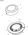
- the partial ring-shaped carrier (7) is disposed at the rear side of the circular illumination aperture (6) ( Figure 4 ).
- the household appliance (1) comprises a stopper (8) disposed on the knob (4) and providing the knob (4) to remain in the desired position when rotated, and more than one protrusion (9) disposed on the inner wall of the housing (3) and enabling the user to sense that he/she selects the desired program parameter by passing over the stopper (8) with the movement of the knob (4).
- the protrusions (9) are arranged in a circular manner in the housing (3) with certain intervals. Each protrusion (9) corresponds to a program parameter predetermined by the producer ( Figure 4 ).
- the household appliance (1) comprises a push-release mechanism (15) having a first element (11) with a channel (10) placed into the housing (3), a second element (13) disposed behind the knob (4) with a pin (12) suitable for moving inside the channel (10) and a spring (14) that provides the second element (13) to move tautly while the pin (12) moves in the channel (10).
- the knob (4) is a push-release type that the knob (4) is outside the housing (3) when used and is hidden inside the housing (3) by being pushed when not used. During the back and forth movement of the pin (12) in the channel (10), the knob (4) exits and enters the housing (3) a little ( Figure 7 ).
- the household appliance (1) comprises more than one segment-shaped retainer (16) enabling the carrier (7) to be mounted to the housing (3) and placed such that a distance remains therebetween.
- the retainers (16) are placed at intervals and in two rows along the base of the housing (3).
- the carrier (7) is mounted between the retainers (16) ( Figure 5 ).
- the household appliance (1) comprises more than one transparent parameter value (17) that is situated around the knob (4) and rotates together with the knob (4), and an indicator (18) disposed on the housing (3) and providing the indication of the parameter value (17) adjusted by means of the knob (4).
- the user brings the desired parameter value (17) to the level of the indicator (18) by rotating the knob (4) ( Figure 2, Figure 3 ).
- the household appliance (1) comprises a light transmitter (19) extending from the light source (5) towards the illumination aperture (6) so as to provide the parameter value (17) at the level of the indicator (18) to be illuminated.
- the light transmitter (19) extends at the level of the indicator (18) and the parameter value (17) remains between the light transmitter (19) and the indicator (18). All the parameter values (17) around the knob (4) are not illuminated ( Figure 2 ).
- the household appliance (1) comprises a circuit board (20) that is placed behind the housing (3) and that controls the operation of the selected program parameters.
- the household appliance (1) comprises at least one connection member (21) that is disposed behind the housing (3) and that provides the circuit board (20) to be fixed to the housing (3) by being slid.
- the circuit board (20) is easily mounted to the housing (3).
- the household appliance (1) comprises a first hole (22) arranged on the base of the housing (3) and a shaft (23) that is disposed at the lower part of the first element (11) and that transmits the movement of the knob (4) to the circuit board (20) by passing through the first hole (22) ( Figure 6 ).
- the household appliance (1) comprises a second hole (25) arranged on the base of the housing (3), through which the cables between the light source (5) and the circuit board (20) pass.
- the connection between the light source (5) and the circuit board (20) is easily realized.
- the household appliance (1) comprises a light source (5) which is a LED light bulb.
- a light source (5) which is a LED light bulb.
- the household appliance (1) is a cooling device, a laundry dryer, a cooking device, a washing machine or a dishwasher.
- the carrier (7) By the light source (5) being placed in the housing (3) by means of the carrier (7), ease of assembly is provided and thus the speed of production is increased. Furthermore, the carrier (7) allows the light source (5) to be easily changed in case of any malfunction.
Landscapes
- Engineering & Computer Science (AREA)
- Physics & Mathematics (AREA)
- General Physics & Mathematics (AREA)
- Automation & Control Theory (AREA)
- Chemical & Material Sciences (AREA)
- Combustion & Propulsion (AREA)
- Mechanical Engineering (AREA)
- General Engineering & Computer Science (AREA)
- Switches With Compound Operations (AREA)
Claims (15)
- Ein Haushaltsgerät (1) umfassend,- eine Öffnung (2) angeordnet auf einem Gehäuse (26),- eine Aufnahme (3), die in die Öffnung (2) eingesetzt ist und von der Öffnung (2) ausgehend in die Innere des Gehäuses (26) erstreckt,- einen zylindrischen Knopf (4), der in die Aufnahme (3) hinein gesteckt und durch Drehen und Schieben bewegt wird, und- eine Lichtquelle (5), die Licht in die Aufnahme (3) ausstrahlt,- einen transparente Beleuchtungsspalt (6), die entlang der Linie, wo die Flächen des Knopf (4) und der seitlichen Wänden sich schneiden, erstreckt, und- einen Träger (7), worauf die Lichtquelle (5) aufgesetzt ist, um den Beleuchtungsspalt (6) nach dem Einstecken Knopfs (4) in die Aufnahme (3) zu beleuchten.
- Haushaltsgerät (1) nach Anspruch 1 gekennzeichnet durch einen ringförmigen Träger (7)
- Haushaltsgerät (1) nach Anspruch 1 gekennzeichnet durch zwei vertikalen Elementen (24, 124), die vom Boden der Aufnahme (3) ausgehend bis zum Knopf (4) erstrecken und die Bewegung des Knopfes (4) in der Aufnahme (3) einschränkt, sowie einen teilweise ringförmigen Träger (7), der zwischen zwei vertikalen Elementen (24, 124) eingesetzt ist.
- Haushaltsgerät (1) nach einem der vorhergehenden Ansprüche gekennzeichnet durch einen Anschlag (8), den man auf den Knopf (4) einsetzt und der sicherstellt , dass der Knopf (4) in der gewünschten Position bleibt, wenn man ihn umdreht und mehrere Vorsprünge (9), die man in die innere Wand der Aufnahme (3) einsetzt und sie sicherstellen, dass der/die Anwender/Anwenderin es fühlt, dass der Knopf (4) in die gewünschte Position mittels der Bewegung des Knopfs (4) durch Übergehen über den Anschlag (8) gebracht ist.
- Haushaltsgerät (1) nach einem der vorhergehenden Ansprüche gekennzeichnet durch mehrere intermittierende Halterteile (16), die die Montage des Trägers (7) in die Aufnahme (3) gewährleistet und die derart angeordnet werden, dass zwischen denen einen Abstand zurückbleibt.
- Haushaltsgerät (1) nach einem der vorhergehenden Ansprüche gekennzeichnet durch mehrere transparente Parameterwertezeichen (17) die am Umfang des Knopfs (4) angeordnet sind und mit dem Knopf (4) zusammen rotieren, und eine Anzeige (18), die auf die Aufnahme (3) eingesetzt wird und die sicherstellt, die eingestellte Parameterwerte (17) mittels des Knopfes (4) angibt.
- Haushaltsgerät (1) nach Anspruch 6 gekennzeichnet durch einen Lichtemitter (19), der von der Lichtquelle (5) ausgehend bis zum Beleuchtungsspalt (6) erstreckt, um den Parameterwert (17) auf der Anzeige (18) zu beleuchten.
- Haushaltsgerät (1) nach einem der vorhergehenden Ansprüche gekennzeichnet durch eine Leiterplatte (20), die hinter der Aufnahme (3) eingesetzt wird und die die Verfahrensparameter des gewählten Programms kontrolliert.
- Haushaltsgerät (1) nach Anspruch 8 gekennzeichnet durch ein Anschlusselement (21), das hinter der Aufnahme (3) eingesetzt wird und sicherstellt, dass die Leiterplatte (20) durch Schieben in die Aufnahme (3) befestigt wird.
- Haushaltsgerät (1) nach Anspruch 8 oder 9 gekennzeichnet durch ein zweites Bohrloch (25), wodurch die Kabeln zwischen der Lichtquelle (5) und der Leiterplatte (20) durchlaufen und das auf dem Boden der Aufnahme (3) angeordnet ist.
- Haushaltsgerät (1) nach einem der vorhergehenden Ansprüche 1 bis 10 gekennzeichnet durch eine Kühlvorrichtung,
- Haushaltsgerät (1) nach einem der vorhergehenden Ansprüche 1 bis 10 gekennzeichnet durch einen Wäschetrockner.
- Haushaltsgerät (1) nach einem der vorhergehenden Ansprüche 1 bis 10 gekennzeichnet durch ein Kochgerät.
- Haushaltsgerät (1) nach einem der vorhergehenden Ansprüche 1 bis 10 gekennzeichnet durch eine Waschmaschine.
- Haushaltsgerät (1) nach einem der vorhergehenden Ansprüche 1 bis 10 gekennzeichnet durch eine Geschirrspülmaschine.
Priority Applications (1)
| Application Number | Priority Date | Filing Date | Title |
|---|---|---|---|
| PL13792019T PL2932344T3 (pl) | 2012-12-14 | 2013-11-18 | Urządzenie gospodarstwa domowego zawierające pokrętło |
Applications Claiming Priority (2)
| Application Number | Priority Date | Filing Date | Title |
|---|---|---|---|
| TR201214710 | 2012-12-14 | ||
| PCT/EP2013/074064 WO2014090511A1 (en) | 2012-12-14 | 2013-11-18 | Household appliance comprising knob |
Publications (2)
| Publication Number | Publication Date |
|---|---|
| EP2932344A1 EP2932344A1 (de) | 2015-10-21 |
| EP2932344B1 true EP2932344B1 (de) | 2017-06-21 |
Family
ID=49585408
Family Applications (1)
| Application Number | Title | Priority Date | Filing Date |
|---|---|---|---|
| EP13792019.5A Active EP2932344B1 (de) | 2012-12-14 | 2013-11-18 | Haushaltgerät umfassend eines knopf |
Country Status (3)
| Country | Link |
|---|---|
| EP (1) | EP2932344B1 (de) |
| PL (1) | PL2932344T3 (de) |
| WO (1) | WO2014090511A1 (de) |
Cited By (1)
| Publication number | Priority date | Publication date | Assignee | Title |
|---|---|---|---|---|
| EP3850273A4 (de) * | 2018-11-13 | 2021-11-17 | Samsung Electronics Co., Ltd. | Knopf und kochgerät damit |
Families Citing this family (2)
| Publication number | Priority date | Publication date | Assignee | Title |
|---|---|---|---|---|
| US10345514B2 (en) | 2017-02-22 | 2019-07-09 | Haier Us Appliance Solutions, Inc. | Appliance and illuminated knob assembly |
| EP3514656A1 (de) * | 2018-01-23 | 2019-07-24 | Hurst + Schröder GmbH | Drehschalter eines elektrischen haushaltsgerätes |
Family Cites Families (4)
| Publication number | Priority date | Publication date | Assignee | Title |
|---|---|---|---|---|
| DE19857837A1 (de) | 1998-12-15 | 2000-06-21 | Mannesmann Vdo Ag | Bedienvorrichtung |
| DE10236935A1 (de) * | 2002-08-12 | 2004-02-26 | BSH Bosch und Siemens Hausgeräte GmbH | Drehschalter für Haushaltsgeräte |
| DE102007024437A1 (de) * | 2007-05-25 | 2008-11-27 | BSH Bosch und Siemens Hausgeräte GmbH | Bedienschalter für ein Haushaltsgerät |
| GB0901923D0 (en) | 2009-02-05 | 2009-03-11 | Sprung Ltd | A knee pad and knee pad assembly |
-
2013
- 2013-11-18 EP EP13792019.5A patent/EP2932344B1/de active Active
- 2013-11-18 WO PCT/EP2013/074064 patent/WO2014090511A1/en not_active Ceased
- 2013-11-18 PL PL13792019T patent/PL2932344T3/pl unknown
Non-Patent Citations (1)
| Title |
|---|
| None * |
Cited By (1)
| Publication number | Priority date | Publication date | Assignee | Title |
|---|---|---|---|---|
| EP3850273A4 (de) * | 2018-11-13 | 2021-11-17 | Samsung Electronics Co., Ltd. | Knopf und kochgerät damit |
Also Published As
| Publication number | Publication date |
|---|---|
| WO2014090511A1 (en) | 2014-06-19 |
| EP2932344A1 (de) | 2015-10-21 |
| PL2932344T3 (pl) | 2017-11-30 |
Similar Documents
| Publication | Publication Date | Title |
|---|---|---|
| US9607792B2 (en) | Knob assemblies with encoder-controlled illumination | |
| US8813676B2 (en) | User interface for a controller | |
| ES2259155T3 (es) | Selector rotativo. | |
| EP3043131A1 (de) | Gerät mit einer mensch-maschine-schnittstelle und beleuchteter griffvertiefung | |
| KR102701592B1 (ko) | 스위치 어셈블리 및 이를 포함하는 조리기기 | |
| AU2011351598A1 (en) | A household appliance comprising a knob the outer periphery of which is illuminated | |
| KR102133189B1 (ko) | 의류처리기기 | |
| US8575501B2 (en) | Household appliance having a user interface with a user-exchangeable touch wheel and rotary encoder | |
| US10036181B2 (en) | Household appliance having a pocket handle and associated display | |
| EP3988699A1 (de) | Waschmaschine | |
| WO2017026960A1 (en) | A household appliance comprising a knob with illuminated outer periphery | |
| US20150299931A1 (en) | Laundry treatment apparatus | |
| WO2014090511A1 (en) | Household appliance comprising knob | |
| US20180238556A1 (en) | Appliance and illuminated knob assembly | |
| US10503286B2 (en) | Household appliance with a user interface element | |
| CN104866005A (zh) | 旋钮机构及带有旋钮机构的家电 | |
| EP2455930A1 (de) | Display zur Anzeige eines Betriebsvorgangs eines Geräts, im Besonderen eines Haushaltsgeräts | |
| US20060164397A1 (en) | Appliance with membrane overlay | |
| US10358761B2 (en) | Household appliance with a rotational user interface element | |
| US8807770B2 (en) | Appliance user interface having reverse mount LEDs | |
| ES2601835T5 (es) | Dispositivo de control de un aparato electrodoméstico | |
| KR20110049269A (ko) | 다이얼 노브 어셈블리 및 이를 포함하는 조리기기 | |
| EP2764524B1 (de) | Haushaltsgerät | |
| KR102853497B1 (ko) | 세탁장치 | |
| WO2015063004A1 (en) | A household appliance comprising a knob |
Legal Events
| Date | Code | Title | Description |
|---|---|---|---|
| PUAI | Public reference made under article 153(3) epc to a published international application that has entered the european phase |
Free format text: ORIGINAL CODE: 0009012 |
|
| 17P | Request for examination filed |
Effective date: 20150521 |
|
| AK | Designated contracting states |
Kind code of ref document: A1 Designated state(s): AL AT BE BG CH CY CZ DE DK EE ES FI FR GB GR HR HU IE IS IT LI LT LU LV MC MK MT NL NO PL PT RO RS SE SI SK SM TR |
|
| AX | Request for extension of the european patent |
Extension state: BA ME |
|
| DAX | Request for extension of the european patent (deleted) | ||
| GRAP | Despatch of communication of intention to grant a patent |
Free format text: ORIGINAL CODE: EPIDOSNIGR1 |
|
| INTG | Intention to grant announced |
Effective date: 20170317 |
|
| GRAS | Grant fee paid |
Free format text: ORIGINAL CODE: EPIDOSNIGR3 |
|
| GRAA | (expected) grant |
Free format text: ORIGINAL CODE: 0009210 |
|
| AK | Designated contracting states |
Kind code of ref document: B1 Designated state(s): AL AT BE BG CH CY CZ DE DK EE ES FI FR GB GR HR HU IE IS IT LI LT LU LV MC MK MT NL NO PL PT RO RS SE SI SK SM TR |
|
| REG | Reference to a national code |
Ref country code: GB Ref legal event code: FG4D |
|
| REG | Reference to a national code |
Ref country code: CH Ref legal event code: EP |
|
| REG | Reference to a national code |
Ref country code: IE Ref legal event code: FG4D |
|
| REG | Reference to a national code |
Ref country code: AT Ref legal event code: REF Ref document number: 903481 Country of ref document: AT Kind code of ref document: T Effective date: 20170715 |
|
| REG | Reference to a national code |
Ref country code: DE Ref legal event code: R096 Ref document number: 602013022625 Country of ref document: DE |
|
| REG | Reference to a national code |
Ref country code: NL Ref legal event code: MP Effective date: 20170621 |
|
| PG25 | Lapsed in a contracting state [announced via postgrant information from national office to epo] |
Ref country code: NO Free format text: LAPSE BECAUSE OF FAILURE TO SUBMIT A TRANSLATION OF THE DESCRIPTION OR TO PAY THE FEE WITHIN THE PRESCRIBED TIME-LIMIT Effective date: 20170921 Ref country code: GR Free format text: LAPSE BECAUSE OF FAILURE TO SUBMIT A TRANSLATION OF THE DESCRIPTION OR TO PAY THE FEE WITHIN THE PRESCRIBED TIME-LIMIT Effective date: 20170922 Ref country code: HR Free format text: LAPSE BECAUSE OF FAILURE TO SUBMIT A TRANSLATION OF THE DESCRIPTION OR TO PAY THE FEE WITHIN THE PRESCRIBED TIME-LIMIT Effective date: 20170621 Ref country code: FI Free format text: LAPSE BECAUSE OF FAILURE TO SUBMIT A TRANSLATION OF THE DESCRIPTION OR TO PAY THE FEE WITHIN THE PRESCRIBED TIME-LIMIT Effective date: 20170621 Ref country code: LT Free format text: LAPSE BECAUSE OF FAILURE TO SUBMIT A TRANSLATION OF THE DESCRIPTION OR TO PAY THE FEE WITHIN THE PRESCRIBED TIME-LIMIT Effective date: 20170621 |
|
| REG | Reference to a national code |
Ref country code: LT Ref legal event code: MG4D |
|
| REG | Reference to a national code |
Ref country code: AT Ref legal event code: MK05 Ref document number: 903481 Country of ref document: AT Kind code of ref document: T Effective date: 20170621 |
|
| REG | Reference to a national code |
Ref country code: FR Ref legal event code: PLFP Year of fee payment: 5 |
|
| PG25 | Lapsed in a contracting state [announced via postgrant information from national office to epo] |
Ref country code: NL Free format text: LAPSE BECAUSE OF FAILURE TO SUBMIT A TRANSLATION OF THE DESCRIPTION OR TO PAY THE FEE WITHIN THE PRESCRIBED TIME-LIMIT Effective date: 20170621 Ref country code: SE Free format text: LAPSE BECAUSE OF FAILURE TO SUBMIT A TRANSLATION OF THE DESCRIPTION OR TO PAY THE FEE WITHIN THE PRESCRIBED TIME-LIMIT Effective date: 20170621 Ref country code: RS Free format text: LAPSE BECAUSE OF FAILURE TO SUBMIT A TRANSLATION OF THE DESCRIPTION OR TO PAY THE FEE WITHIN THE PRESCRIBED TIME-LIMIT Effective date: 20170621 Ref country code: BG Free format text: LAPSE BECAUSE OF FAILURE TO SUBMIT A TRANSLATION OF THE DESCRIPTION OR TO PAY THE FEE WITHIN THE PRESCRIBED TIME-LIMIT Effective date: 20170921 Ref country code: LV Free format text: LAPSE BECAUSE OF FAILURE TO SUBMIT A TRANSLATION OF THE DESCRIPTION OR TO PAY THE FEE WITHIN THE PRESCRIBED TIME-LIMIT Effective date: 20170621 |
|
| PG25 | Lapsed in a contracting state [announced via postgrant information from national office to epo] |
Ref country code: AT Free format text: LAPSE BECAUSE OF FAILURE TO SUBMIT A TRANSLATION OF THE DESCRIPTION OR TO PAY THE FEE WITHIN THE PRESCRIBED TIME-LIMIT Effective date: 20170621 Ref country code: RO Free format text: LAPSE BECAUSE OF FAILURE TO SUBMIT A TRANSLATION OF THE DESCRIPTION OR TO PAY THE FEE WITHIN THE PRESCRIBED TIME-LIMIT Effective date: 20170621 Ref country code: EE Free format text: LAPSE BECAUSE OF FAILURE TO SUBMIT A TRANSLATION OF THE DESCRIPTION OR TO PAY THE FEE WITHIN THE PRESCRIBED TIME-LIMIT Effective date: 20170621 Ref country code: SK Free format text: LAPSE BECAUSE OF FAILURE TO SUBMIT A TRANSLATION OF THE DESCRIPTION OR TO PAY THE FEE WITHIN THE PRESCRIBED TIME-LIMIT Effective date: 20170621 Ref country code: CZ Free format text: LAPSE BECAUSE OF FAILURE TO SUBMIT A TRANSLATION OF THE DESCRIPTION OR TO PAY THE FEE WITHIN THE PRESCRIBED TIME-LIMIT Effective date: 20170621 |
|
| PG25 | Lapsed in a contracting state [announced via postgrant information from national office to epo] |
Ref country code: IS Free format text: LAPSE BECAUSE OF FAILURE TO SUBMIT A TRANSLATION OF THE DESCRIPTION OR TO PAY THE FEE WITHIN THE PRESCRIBED TIME-LIMIT Effective date: 20171021 Ref country code: ES Free format text: LAPSE BECAUSE OF FAILURE TO SUBMIT A TRANSLATION OF THE DESCRIPTION OR TO PAY THE FEE WITHIN THE PRESCRIBED TIME-LIMIT Effective date: 20170621 Ref country code: SM Free format text: LAPSE BECAUSE OF FAILURE TO SUBMIT A TRANSLATION OF THE DESCRIPTION OR TO PAY THE FEE WITHIN THE PRESCRIBED TIME-LIMIT Effective date: 20170621 |
|
| REG | Reference to a national code |
Ref country code: DE Ref legal event code: R097 Ref document number: 602013022625 Country of ref document: DE |
|
| PLBE | No opposition filed within time limit |
Free format text: ORIGINAL CODE: 0009261 |
|
| STAA | Information on the status of an ep patent application or granted ep patent |
Free format text: STATUS: NO OPPOSITION FILED WITHIN TIME LIMIT |
|
| PG25 | Lapsed in a contracting state [announced via postgrant information from national office to epo] |
Ref country code: DK Free format text: LAPSE BECAUSE OF FAILURE TO SUBMIT A TRANSLATION OF THE DESCRIPTION OR TO PAY THE FEE WITHIN THE PRESCRIBED TIME-LIMIT Effective date: 20170621 |
|
| 26N | No opposition filed |
Effective date: 20180322 |
|
| PG25 | Lapsed in a contracting state [announced via postgrant information from national office to epo] |
Ref country code: MC Free format text: LAPSE BECAUSE OF FAILURE TO SUBMIT A TRANSLATION OF THE DESCRIPTION OR TO PAY THE FEE WITHIN THE PRESCRIBED TIME-LIMIT Effective date: 20170621 |
|
| PG25 | Lapsed in a contracting state [announced via postgrant information from national office to epo] |
Ref country code: LI Free format text: LAPSE BECAUSE OF NON-PAYMENT OF DUE FEES Effective date: 20171130 Ref country code: CH Free format text: LAPSE BECAUSE OF NON-PAYMENT OF DUE FEES Effective date: 20171130 |
|
| PG25 | Lapsed in a contracting state [announced via postgrant information from national office to epo] |
Ref country code: LU Free format text: LAPSE BECAUSE OF NON-PAYMENT OF DUE FEES Effective date: 20171118 Ref country code: SI Free format text: LAPSE BECAUSE OF FAILURE TO SUBMIT A TRANSLATION OF THE DESCRIPTION OR TO PAY THE FEE WITHIN THE PRESCRIBED TIME-LIMIT Effective date: 20170621 |
|
| REG | Reference to a national code |
Ref country code: BE Ref legal event code: MM Effective date: 20171130 |
|
| REG | Reference to a national code |
Ref country code: IE Ref legal event code: MM4A |
|
| PG25 | Lapsed in a contracting state [announced via postgrant information from national office to epo] |
Ref country code: MT Free format text: LAPSE BECAUSE OF NON-PAYMENT OF DUE FEES Effective date: 20171118 |
|
| PG25 | Lapsed in a contracting state [announced via postgrant information from national office to epo] |
Ref country code: IE Free format text: LAPSE BECAUSE OF NON-PAYMENT OF DUE FEES Effective date: 20171118 |
|
| PG25 | Lapsed in a contracting state [announced via postgrant information from national office to epo] |
Ref country code: BE Free format text: LAPSE BECAUSE OF NON-PAYMENT OF DUE FEES Effective date: 20171130 |
|
| PG25 | Lapsed in a contracting state [announced via postgrant information from national office to epo] |
Ref country code: HU Free format text: LAPSE BECAUSE OF FAILURE TO SUBMIT A TRANSLATION OF THE DESCRIPTION OR TO PAY THE FEE WITHIN THE PRESCRIBED TIME-LIMIT; INVALID AB INITIO Effective date: 20131118 |
|
| PG25 | Lapsed in a contracting state [announced via postgrant information from national office to epo] |
Ref country code: CY Free format text: LAPSE BECAUSE OF FAILURE TO SUBMIT A TRANSLATION OF THE DESCRIPTION OR TO PAY THE FEE WITHIN THE PRESCRIBED TIME-LIMIT Effective date: 20170621 |
|
| PG25 | Lapsed in a contracting state [announced via postgrant information from national office to epo] |
Ref country code: MK Free format text: LAPSE BECAUSE OF FAILURE TO SUBMIT A TRANSLATION OF THE DESCRIPTION OR TO PAY THE FEE WITHIN THE PRESCRIBED TIME-LIMIT Effective date: 20170621 |
|
| PG25 | Lapsed in a contracting state [announced via postgrant information from national office to epo] |
Ref country code: PT Free format text: LAPSE BECAUSE OF FAILURE TO SUBMIT A TRANSLATION OF THE DESCRIPTION OR TO PAY THE FEE WITHIN THE PRESCRIBED TIME-LIMIT Effective date: 20170621 |
|
| PG25 | Lapsed in a contracting state [announced via postgrant information from national office to epo] |
Ref country code: AL Free format text: LAPSE BECAUSE OF FAILURE TO SUBMIT A TRANSLATION OF THE DESCRIPTION OR TO PAY THE FEE WITHIN THE PRESCRIBED TIME-LIMIT Effective date: 20170621 |
|
| PGFP | Annual fee paid to national office [announced via postgrant information from national office to epo] |
Ref country code: DE Payment date: 20251119 Year of fee payment: 13 |
|
| PGFP | Annual fee paid to national office [announced via postgrant information from national office to epo] |
Ref country code: GB Payment date: 20251121 Year of fee payment: 13 |
|
| PGFP | Annual fee paid to national office [announced via postgrant information from national office to epo] |
Ref country code: IT Payment date: 20251125 Year of fee payment: 13 |
|
| PGFP | Annual fee paid to national office [announced via postgrant information from national office to epo] |
Ref country code: FR Payment date: 20251125 Year of fee payment: 13 |
|
| PGFP | Annual fee paid to national office [announced via postgrant information from national office to epo] |
Ref country code: TR Payment date: 20251111 Year of fee payment: 13 |
|
| PGFP | Annual fee paid to national office [announced via postgrant information from national office to epo] |
Ref country code: PL Payment date: 20251107 Year of fee payment: 13 |