EP2932211B1 - Wrist-worn device for sensing ambient light intensity - Google Patents
Wrist-worn device for sensing ambient light intensity Download PDFInfo
- Publication number
- EP2932211B1 EP2932211B1 EP13826856.0A EP13826856A EP2932211B1 EP 2932211 B1 EP2932211 B1 EP 2932211B1 EP 13826856 A EP13826856 A EP 13826856A EP 2932211 B1 EP2932211 B1 EP 2932211B1
- Authority
- EP
- European Patent Office
- Prior art keywords
- wrist
- light
- worn device
- sensor
- sensors
- Prior art date
- Legal status (The legal status is an assumption and is not a legal conclusion. Google has not performed a legal analysis and makes no representation as to the accuracy of the status listed.)
- Active
Links
Images

Classifications
-
- G—PHYSICS
- G01—MEASURING; TESTING
- G01J—MEASUREMENT OF INTENSITY, VELOCITY, SPECTRAL CONTENT, POLARISATION, PHASE OR PULSE CHARACTERISTICS OF INFRARED, VISIBLE OR ULTRAVIOLET LIGHT; COLORIMETRY; RADIATION PYROMETRY
- G01J1/00—Photometry, e.g. photographic exposure meter
- G01J1/42—Photometry, e.g. photographic exposure meter using electric radiation detectors
- G01J1/44—Electric circuits
-
- G—PHYSICS
- G01—MEASURING; TESTING
- G01J—MEASUREMENT OF INTENSITY, VELOCITY, SPECTRAL CONTENT, POLARISATION, PHASE OR PULSE CHARACTERISTICS OF INFRARED, VISIBLE OR ULTRAVIOLET LIGHT; COLORIMETRY; RADIATION PYROMETRY
- G01J1/00—Photometry, e.g. photographic exposure meter
- G01J1/02—Details
- G01J1/0233—Handheld
-
- G—PHYSICS
- G01—MEASURING; TESTING
- G01J—MEASUREMENT OF INTENSITY, VELOCITY, SPECTRAL CONTENT, POLARISATION, PHASE OR PULSE CHARACTERISTICS OF INFRARED, VISIBLE OR ULTRAVIOLET LIGHT; COLORIMETRY; RADIATION PYROMETRY
- G01J1/00—Photometry, e.g. photographic exposure meter
- G01J1/02—Details
- G01J1/0242—Control or determination of height or angle information of sensors or receivers; Goniophotometry
-
- G—PHYSICS
- G01—MEASURING; TESTING
- G01J—MEASUREMENT OF INTENSITY, VELOCITY, SPECTRAL CONTENT, POLARISATION, PHASE OR PULSE CHARACTERISTICS OF INFRARED, VISIBLE OR ULTRAVIOLET LIGHT; COLORIMETRY; RADIATION PYROMETRY
- G01J1/00—Photometry, e.g. photographic exposure meter
- G01J1/02—Details
- G01J1/0271—Housings; Attachments or accessories for photometers
-
- G—PHYSICS
- G01—MEASURING; TESTING
- G01J—MEASUREMENT OF INTENSITY, VELOCITY, SPECTRAL CONTENT, POLARISATION, PHASE OR PULSE CHARACTERISTICS OF INFRARED, VISIBLE OR ULTRAVIOLET LIGHT; COLORIMETRY; RADIATION PYROMETRY
- G01J1/00—Photometry, e.g. photographic exposure meter
- G01J1/02—Details
- G01J1/04—Optical or mechanical part supplementary adjustable parts
- G01J1/0407—Optical elements not provided otherwise, e.g. manifolds, windows, holograms, gratings
- G01J1/0425—Optical elements not provided otherwise, e.g. manifolds, windows, holograms, gratings using optical fibers
-
- G—PHYSICS
- G01—MEASURING; TESTING
- G01J—MEASUREMENT OF INTENSITY, VELOCITY, SPECTRAL CONTENT, POLARISATION, PHASE OR PULSE CHARACTERISTICS OF INFRARED, VISIBLE OR ULTRAVIOLET LIGHT; COLORIMETRY; RADIATION PYROMETRY
- G01J1/00—Photometry, e.g. photographic exposure meter
- G01J1/42—Photometry, e.g. photographic exposure meter using electric radiation detectors
- G01J1/4204—Photometry, e.g. photographic exposure meter using electric radiation detectors with determination of ambient light
-
- G—PHYSICS
- G01—MEASURING; TESTING
- G01J—MEASUREMENT OF INTENSITY, VELOCITY, SPECTRAL CONTENT, POLARISATION, PHASE OR PULSE CHARACTERISTICS OF INFRARED, VISIBLE OR ULTRAVIOLET LIGHT; COLORIMETRY; RADIATION PYROMETRY
- G01J1/00—Photometry, e.g. photographic exposure meter
- G01J1/42—Photometry, e.g. photographic exposure meter using electric radiation detectors
- G01J1/4228—Photometry, e.g. photographic exposure meter using electric radiation detectors arrangements with two or more detectors, e.g. for sensitivity compensation
Definitions
- the invention relates to the field of wrist-worn devices for sensing ambient light intensity, as well as to a corresponding method for sensing ambient light intensity using such a wrist-worn device.
- Exposure to light is the key mechanism that enables a proper synchronization of the body clock with the solar day cycle. Timing, duration, intensity and spectral composition of light exposure all have impact on the so-called entrainment of a person to a 24-hour circadian rhythm. It has been shown that restorative sleep can only occur in synchronicity with the body clock. For certain people who have a phase shift of their internal body clock relative to the social schedules around them, exposure to bright light at welldefined times can be used to shift their body clock forward or backwards to better align it with their social needs. Also for the treatment of seasonal affective disorder, timed and regular exposure to bright light is an effective means.
- Such a wrist-worn device is shown, for example, in US 2008/0319354 A1 , showing a system and method for monitoring information related to sleep.
- the wrist-worn device shown in this document comprises an illumination sensor to provide information related to the intensity of ambient illumination of the user.
- the signal of the sensor can be further processed by suitable electronic computing means.
- UK patent application GB 2358919 discloses a light monitoring device comprising at least one light sensitive element and recording means. The output from the or each element is recordable by the recording means. The recorded data is related to the lighting conditions around the device. A programme running on the computer is able to extract the memorised data and construct a virtual spacial distribution of light.
- EP patent application EP 0930512 A1 discloses a system intended to determine the orientation in the space of a body integral with a photoreceiver, comprised of three photosensors which receive light from a photoemitter, and which provides through an electronic calculation subsystem to determine the direction of the incident radiation.
- the common sensor modules are usually mounted such that the axis of main sensitivity is orthogonal to the display surface of the operation module, i.e., orthogonal to the outer hand surface of the user.
- the axis of main sensitivity of the sensor is completely independent from the direction of gaze of the user, with the consequence that there is no good correlation between the light levels being measured and those light levels present at the user's eyes which would be optimal for the estimation of the visual and non-visual effects caused by light exposure such as e.g., shifting human circadian phase.
- the main axis of sensitivity is different from the direction from which the main portion of ambient light is received.
- the wrist-worn device for sensing ambient light intensity comprises not only one but a plurality of light receivers arranged at different positions of the wrist-worn device in different orientations to receive light from different directions.
- the effect of a directional receptivity of one of the receivers is counterbalanced by different receivers pointing in different directions, so that a multi-directional measurement is possible.
- With increasing number of light receivers used in this arrangement a quasi omni-directional light measurement is possible, being almost independent from the present orientation of the wrist-worn device on the body of the user.
- the light receivers are light sensors that collect light and convert the received light intensity into a corresponding electric signal that can be further processed.
- the receptivity of the light receiver corresponds to the sensitivity of the sensor.
- each of the different directions corresponds to a main axis of maximum receptivity of one of the light receivers.
- the maximum receptivity corresponds to the maximum sensitivity of the sensor on its main axis.
- At least some of the different directions are orthogonal to each other.
- one of the light receivers may be placed on top of the wrist-worn device, with its main axis of maximum receptivity standing orthogonal to the back of the hand of the user, while another light receiver is arranged laterally at the wrist-worn device, pointing in a direction orthogonal to the first light receiver.
- two different light receivers can be arranged on opposite sides of the wrist-worn device.
- the light receivers are arranged in pairs, wherein the two light receivers of each pair are arranged in opposite orientations on one spatial axis of a Cartesian coordinate system.
- six light receivers can be used in total, with three pairs of light receivers on the spatial axes of a three dimensional coordinate system.
- the wrist-worn device comprises an operation module and a wrist band connected with its ends to opposite sides of the operation module, and the light receivers are arranged in different positions on the operation module and/or the wrist band.
- the operation module can be, for example, a housing receiving an integrated circuit for processing and storing the signals provided by sensors used as light receivers, comparable to the housing of a common wrist watch.
- the light receivers are sensors for generating a signal corresponding to the received light intensity.
- the light receivers are connected via light conductors with one common sensor that collects the light received by the light receivers.
- the light receivers themselves are not provided as sensors but only as optical light collecting devices, such as optical lenses, coupled to light conduction fibers that supply the collected light towards the sensor for further processing.
- the light receivers are provided to receive light of one or a plurality of spectral ranges, for example, within the visible light spectrum or also including the infrared or ultraviolet spectral range.
- the wrist-worn device further comprises a central processing unit for processing signals representing the intensities received by the light receivers and for identifying and further processing a signal representing a maximum intensity among these intensities.
- a central processing unit for processing signals representing the intensities received by the light receivers and for identifying and further processing a signal representing a maximum intensity among these intensities.
- only the signal of the light receiver having received the maximum intensity among all receivers is further processed.
- the central processing unit is provided for identifying and further processing a signal representing the maximum intensity in one predetermined spectral range.
- the wrist-worn device comprises a central processing unit for processing signals representing the intensities received by the light receivers and for combining these signals to one general intensity signal.
- This combination can be achieved, for example, by adding all signals of the light receivers, or by any other linear or non-linear combination of them.
- the wrist-worn device further comprises an accelerometer for sensing the spatial orientation of the of the wrist-worn device.
- the signal of the accelerometer can be used to identify, for example, the light receiver that points to the ground, or another light receiver that points to the ceiling or to the sky. This information can be used to enhance the overall sensing sensitivity from the spatial arrangement of the light receivers.
- the invention also refers to a method for sensing ambient light intensity using a wrist-worn device of the above kind, comprising the steps of supplying signals representing the intensities received by the light receivers to the central processing unit, comparing the supplied signals, and identifying a signal representing the maximum intensity among the received intensities.
- Another method for sensing ambient light intensity comprises the steps of supplying signals representing the intensities received by the light receivers to central processing unit, and combining the supplying signals to one general intensity signal.
- Fig. 1 shows a wrist-worn device 10 for sensing the ambient light intensity in the environment of a user (not shown) wearing this device 10.
- the wrist-worn device 10 comprises an operation module 12 in the shape of a flat rectangular box, and a flexible wrist band 14 that is attached with its ends to opposite sides of the operation module 12 such that the operation module 12 and the wrist band 14 form a ring.
- the inner diameter of the wrist band 14 is dimensioned such that the wrist-worn device 10 can comfortably be worn on the wrist of a user.
- the wrist band 14 may have a certain elasticity to be widened, or a opening and closing mechanism (not shown in the Figures) may be provided for connecting one end of the wrist band 14 to the operation module 12.
- the operation module 12 and the wrist band 14 are formed similar to a common wrist watch.
- the operation module 12 is formed as a housing that receives an integrated electronic circuit for processing and storing electric signals, as will be described further below.
- a display 18 for displaying a status information of the device 10 or any other information, like, for example, the daytime.
- a light sensor 20 for measuring the ambient light intensity.
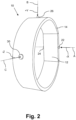
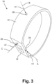
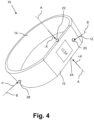
- Other sensors 22 and 24 are arranged laterally at the operation module 12, while another sensor 26 is arranged on top of the wrist band 14 (with respect to the orientation in Fig. 1 ), a fifth light sensor 28 is positioned opposite to the top sensor 26 on the bottom of the wrist band 14, and finally a sixth sensor (not shown in Fig. 1 but present in Fig. 2 ) is located on the back of the wrist band, opposite to the front sensor 20 on top of the operation module 12.
- All sensors 20, 22, 24, 26, 28, 30 are arranged at different positions of the wrist-worn device 10 to receive light from different directions. Each of these directions corresponds to a main axis of maximum sensitivity of one of the sensors 20, 22, 24, 26, 28, 30.
- the right sensor 24 on the right side of the operation module 12 is oriented such that it receives light from the right side in Fig. 1 , and this sensor 24 has a main axis of maximum sensitivity marked by a dashed line A that stands perpendicular to the side wall of the operation module 12 and to the ring plane of the wrist band 14. In this axis A, the sensitivity of the sensor 24 is at its maximum.
- the sensor 24 is positioned to receive light from a direction +X (marked by an arrow in Fig. 1 ) along its main axis A.
- the sensor 22 is arranged on the opposite lateral side of the operation module 12, with its main axis of maximum sensitivity falling together with the axis A of the sensor 24 described before. However, this left sensor 22 is arranged to receive light from the opposite direction -X (also marked by an arrow opposite to the arrow +X in Fig. 1 ) along this axis A. As a result, both opposite sensors 22 and 24 are opposite to each other, arranged to receive light from opposite directions +X, -X on a common axis A of maximum sensitivity.
- the top sensor 26 and the bottom sensor 28 are also arranged opposite to each other to receive light from opposite directions. Namely, the top sensor 26 is arranged to receive light from a top direction +Y perpendicular to the surface of the wrist band 14, while the bottom sensor 28 is arranged to receive light from the opposite direction -Y, while the marked directions +Y, -Y both lie on the same main axis B representing the maximum sensitivity of the sensors 26 and 28.
- This second main axis B of sensitivity is marked by the dashed line in Fig. 1 . It is noted that this second main axis B of maximum sensitivity stands perpendicular to the first main axis A of maximum sensitivity of the left and right sensors 22 and 24.
- front sensor 20 on top of the operation module 12 and the back sensor 30 are opposite to each other to receive light from the opposite directions marked by arrows +Z, -Z.
- Each of these directions +Z, -Z lies on a main axis C of maximum sensitivity of the front and back sensors 20 and 30.
- each two light sensors of the six light sensors 20, 22, 24, 26, 28, 30 are arranged in pairs, wherein two light sensors of one pair are arranged in opposite orientations +X, -X, +Y, -Y, and +Z, -Z, respectively, on one spatial axis of a Cartesian coordinate system spanned by the orthogonal axes of these pairs.
- These orthogonal axes are represented by the described axes A, B, and C of maximum sensitivity of the sensors 20, 22, 24, 26, 28, 30.
- each two sensors are arranged orthogonal to each other, for example the left sensor 22 and the top sensor 26, the right sensor 24 and the bottom sensor 28, or the top sensor 26 and the back sensor 30, and so forth.
- sensors are used as light receivers to transform light into an electric signal that can be further processed and/or stored by a central processing unit in the operation module 12.
- the sensors 20, 22, 24, 26, 28, 30 are represented by opto-sensitive electronic components.
- other kinds of light receivers in place of the sensors 20, 22, 24, 26, 28, 30 at the same positions and with the same orientations, that also have a main axis of maximum receptivity for light, in form of optical elements that collect light and further supply the collected light via light conductors towards a common sensor that is housed within the operation module 12, so that the electric signal is generated by this common sensor.
- the light receivers i.e., sensors or any other kinds of light collecting optical elements
- the central processing unit may then process signals representing the intensities received by the light receivers and identify the signal that represents the maximum measured intensity, for further storing and/or processing. This means that the central processing unit decides which of the light receivers or sensors measures the maximum intensity, and further processes only the signals of this identified sensor. It is further possible to carry out this identification and further processing on one selected spectral range of the sensors.
- Another possibility is to combine the signals of all light receivers or light sensors to one general intensity signal within the central processing unit, by any linear or non-linear combination.
- This processing can also be weighted by an accelerometer (not shown) that is provided within the operation module 12 for sensing the spatial orientation of the wrist-worn device 10.
- an accelerometer not shown
Landscapes
- Physics & Mathematics (AREA)
- General Physics & Mathematics (AREA)
- Spectroscopy & Molecular Physics (AREA)
- Life Sciences & Earth Sciences (AREA)
- Sustainable Development (AREA)
- Measuring Pulse, Heart Rate, Blood Pressure Or Blood Flow (AREA)
- Photometry And Measurement Of Optical Pulse Characteristics (AREA)
- Optical Communication System (AREA)
Applications Claiming Priority (2)
| Application Number | Priority Date | Filing Date | Title |
|---|---|---|---|
| US201261737165P | 2012-12-14 | 2012-12-14 | |
| PCT/IB2013/060322 WO2014091340A1 (en) | 2012-12-14 | 2013-11-22 | Wrist-worn device for sensing ambient light intensity |
Publications (2)
| Publication Number | Publication Date |
|---|---|
| EP2932211A1 EP2932211A1 (en) | 2015-10-21 |
| EP2932211B1 true EP2932211B1 (en) | 2024-11-20 |
Family
ID=50033599
Family Applications (1)
| Application Number | Title | Priority Date | Filing Date |
|---|---|---|---|
| EP13826856.0A Active EP2932211B1 (en) | 2012-12-14 | 2013-11-22 | Wrist-worn device for sensing ambient light intensity |
Country Status (5)
| Country | Link |
|---|---|
| US (1) | US9752930B2 (enExample) |
| EP (1) | EP2932211B1 (enExample) |
| JP (1) | JP6248122B2 (enExample) |
| CN (1) | CN104870953B (enExample) |
| WO (1) | WO2014091340A1 (enExample) |
Families Citing this family (3)
| Publication number | Priority date | Publication date | Assignee | Title |
|---|---|---|---|---|
| US7656393B2 (en) | 2005-03-04 | 2010-02-02 | Apple Inc. | Electronic device having display and surrounding touch sensitive bezel for user interface and control |
| FR3019320B1 (fr) * | 2014-03-28 | 2017-12-15 | Fogale Nanotech | Dispositif electronique de type montre-bracelet avec interface de commande sans contact et procede de controle d'un tel dispositif |
| US10324620B2 (en) | 2016-09-06 | 2019-06-18 | Apple Inc. | Processing capacitive touch gestures implemented on an electronic device |
Citations (2)
| Publication number | Priority date | Publication date | Assignee | Title |
|---|---|---|---|---|
| GB2358919A (en) * | 2000-01-26 | 2001-08-08 | Andrew Steven Russell | Measuring and modelling light distribution |
| US20080165116A1 (en) * | 2007-01-05 | 2008-07-10 | Herz Scott M | Backlight and Ambient Light Sensor System |
Family Cites Families (18)
| Publication number | Priority date | Publication date | Assignee | Title |
|---|---|---|---|---|
| US4491727A (en) * | 1981-07-01 | 1985-01-01 | Ramot University Authority For Applied Research | Solar radiation sensor and system including same for measuring solar radiation distribution |
| JPS6140689U (ja) * | 1984-08-20 | 1986-03-14 | カシオ計算機株式会社 | 電子腕時計のスイツチ構造 |
| JPH02115726A (ja) * | 1988-10-25 | 1990-04-27 | Matsushita Electric Works Ltd | 受光量計測装置 |
| US4975584A (en) * | 1989-03-29 | 1990-12-04 | Mountain Ocean, Ltd. | Method and apparatus for collecting, processing and displaying ultraviolet radiation data |
| JPH063188A (ja) * | 1992-06-22 | 1994-01-11 | Nippon Telegr & Teleph Corp <Ntt> | 紫外線識別センサ |
| ES2119697B1 (es) * | 1996-09-13 | 1999-04-16 | Infrarrojo Y Microelectronica | Fotosensor vectorial. |
| US6084228A (en) * | 1998-11-09 | 2000-07-04 | Control Devices, Inc. | Dual zone solar sensor |
| JP4042340B2 (ja) * | 2000-05-17 | 2008-02-06 | カシオ計算機株式会社 | 情報機器 |
| US7192136B2 (en) * | 2003-04-15 | 2007-03-20 | Howell Thomas A | Tethered electrical components for eyeglasses |
| EP1671276B1 (en) | 2003-09-30 | 2007-09-05 | Koninklijke Philips Electronics N.V. | Image rendering with interactive motion parallax |
| DE102004028022B4 (de) | 2004-06-09 | 2006-11-16 | Perkinelmer Optoelectronics Gmbh & Co.Kg | Sensor |
| JP4607709B2 (ja) | 2005-08-26 | 2011-01-05 | シャープ株式会社 | 検出装置 |
| US8852127B2 (en) * | 2007-06-08 | 2014-10-07 | Ric Investments, Llc | System and method for monitoring information related to sleep |
| TWM341193U (en) * | 2008-02-05 | 2008-09-21 | Tennrich Int Corp | Display apparatus for displaying light intensity and its application |
| EP3266383A1 (en) | 2009-10-23 | 2018-01-10 | Koninklijke Philips N.V. | Optical sensing - enabled interventional instruments for rapid distributed measurements of pressure |
| US9579521B2 (en) | 2010-01-21 | 2017-02-28 | Koninklijke Philips N.V. | Control device, wearable device and lighting system for light therapy purposes |
| EP2460464A1 (en) | 2010-12-03 | 2012-06-06 | Koninklijke Philips Electronics N.V. | Sleep disturbance monitoring apparatus |
| CN202284971U (zh) * | 2011-10-08 | 2012-06-27 | 江苏科融电子技术有限公司 | 用于热释电红外传感器的半导体封装结构件及其传感器 |
-
2013
- 2013-11-22 US US14/647,842 patent/US9752930B2/en active Active
- 2013-11-22 EP EP13826856.0A patent/EP2932211B1/en active Active
- 2013-11-22 JP JP2015547209A patent/JP6248122B2/ja active Active
- 2013-11-22 WO PCT/IB2013/060322 patent/WO2014091340A1/en not_active Ceased
- 2013-11-22 CN CN201380065133.0A patent/CN104870953B/zh active Active
Patent Citations (2)
| Publication number | Priority date | Publication date | Assignee | Title |
|---|---|---|---|---|
| GB2358919A (en) * | 2000-01-26 | 2001-08-08 | Andrew Steven Russell | Measuring and modelling light distribution |
| US20080165116A1 (en) * | 2007-01-05 | 2008-07-10 | Herz Scott M | Backlight and Ambient Light Sensor System |
Also Published As
| Publication number | Publication date |
|---|---|
| CN104870953B (zh) | 2018-03-27 |
| US20150346026A1 (en) | 2015-12-03 |
| US9752930B2 (en) | 2017-09-05 |
| CN104870953A (zh) | 2015-08-26 |
| JP6248122B2 (ja) | 2017-12-13 |
| EP2932211A1 (en) | 2015-10-21 |
| WO2014091340A1 (en) | 2014-06-19 |
| JP2016503882A (ja) | 2016-02-08 |
Similar Documents
| Publication | Publication Date | Title |
|---|---|---|
| US12343120B2 (en) | Athletic performance monitoring system utilizing heart rate information | |
| EP3039390B1 (en) | System for sensing light exposure of a user | |
| Figueiro et al. | Comparisons of three practical field devices used to measure personal light exposures and activity levels | |
| US10274901B2 (en) | Wearable article | |
| CN108012445A (zh) | 包括生物测定传感器的电子设备 | |
| US20170014071A1 (en) | Magnet-based monitoring system | |
| EP2932211B1 (en) | Wrist-worn device for sensing ambient light intensity | |
| CN115177240B (zh) | 基于可穿戴设备的光环境及姿态检测方法、装置、系统 | |
| US20160228055A1 (en) | Vaporization heat quantity measuring device, biological information measuring device, and electronic apparatus | |
| JP2016503882A5 (enExample) | ||
| Figueiro et al. | New tools to measure light exposure, activity, and circadian disruption in older adults | |
| IT202000009541A1 (it) | Dispositivo diagnostico portatile | |
| CN110623672A (zh) | 一种失能检测及监测方法和失能检测及监测设备 | |
| SK500362015A3 (sk) | Spôsob získavania a/alebo spracovania neuromarketingových dát, systém na jeho uskutočnenie |
Legal Events
| Date | Code | Title | Description |
|---|---|---|---|
| PUAI | Public reference made under article 153(3) epc to a published international application that has entered the european phase |
Free format text: ORIGINAL CODE: 0009012 |
|
| 17P | Request for examination filed |
Effective date: 20150714 |
|
| AK | Designated contracting states |
Kind code of ref document: A1 Designated state(s): AL AT BE BG CH CY CZ DE DK EE ES FI FR GB GR HR HU IE IS IT LI LT LU LV MC MK MT NL NO PL PT RO RS SE SI SK SM TR |
|
| AX | Request for extension of the european patent |
Extension state: BA ME |
|
| DAX | Request for extension of the european patent (deleted) | ||
| STAA | Information on the status of an ep patent application or granted ep patent |
Free format text: STATUS: EXAMINATION IS IN PROGRESS |
|
| 17Q | First examination report despatched |
Effective date: 20190612 |
|
| RAP1 | Party data changed (applicant data changed or rights of an application transferred) |
Owner name: KONINKLIJKE PHILIPS N.V. |
|
| GRAP | Despatch of communication of intention to grant a patent |
Free format text: ORIGINAL CODE: EPIDOSNIGR1 |
|
| STAA | Information on the status of an ep patent application or granted ep patent |
Free format text: STATUS: GRANT OF PATENT IS INTENDED |
|
| GRAJ | Information related to disapproval of communication of intention to grant by the applicant or resumption of examination proceedings by the epo deleted |
Free format text: ORIGINAL CODE: EPIDOSDIGR1 |
|
| STAA | Information on the status of an ep patent application or granted ep patent |
Free format text: STATUS: EXAMINATION IS IN PROGRESS |
|
| INTG | Intention to grant announced |
Effective date: 20240430 |
|
| INTC | Intention to grant announced (deleted) | ||
| GRAP | Despatch of communication of intention to grant a patent |
Free format text: ORIGINAL CODE: EPIDOSNIGR1 |
|
| STAA | Information on the status of an ep patent application or granted ep patent |
Free format text: STATUS: GRANT OF PATENT IS INTENDED |
|
| INTG | Intention to grant announced |
Effective date: 20240620 |
|
| GRAS | Grant fee paid |
Free format text: ORIGINAL CODE: EPIDOSNIGR3 |
|
| GRAA | (expected) grant |
Free format text: ORIGINAL CODE: 0009210 |
|
| STAA | Information on the status of an ep patent application or granted ep patent |
Free format text: STATUS: THE PATENT HAS BEEN GRANTED |
|
| AK | Designated contracting states |
Kind code of ref document: B1 Designated state(s): AL AT BE BG CH CY CZ DE DK EE ES FI FR GB GR HR HU IE IS IT LI LT LU LV MC MK MT NL NO PL PT RO RS SE SI SK SM TR |
|
| REG | Reference to a national code |
Ref country code: GB Ref legal event code: FG4D |
|
| REG | Reference to a national code |
Ref country code: CH Ref legal event code: EP |
|
| REG | Reference to a national code |
Ref country code: DE Ref legal event code: R096 Ref document number: 602013086312 Country of ref document: DE |
|
| REG | Reference to a national code |
Ref country code: IE Ref legal event code: FG4D |
|
| PGFP | Annual fee paid to national office [announced via postgrant information from national office to epo] |
Ref country code: DE Payment date: 20241128 Year of fee payment: 12 |
|
| PGFP | Annual fee paid to national office [announced via postgrant information from national office to epo] |
Ref country code: GB Payment date: 20241126 Year of fee payment: 12 |
|
| PGFP | Annual fee paid to national office [announced via postgrant information from national office to epo] |
Ref country code: FR Payment date: 20241126 Year of fee payment: 12 |
|
| REG | Reference to a national code |
Ref country code: LT Ref legal event code: MG9D |
|
| REG | Reference to a national code |
Ref country code: NL Ref legal event code: MP Effective date: 20241120 |
|
| PG25 | Lapsed in a contracting state [announced via postgrant information from national office to epo] |
Ref country code: HR Free format text: LAPSE BECAUSE OF FAILURE TO SUBMIT A TRANSLATION OF THE DESCRIPTION OR TO PAY THE FEE WITHIN THE PRESCRIBED TIME-LIMIT Effective date: 20241120 Ref country code: IS Free format text: LAPSE BECAUSE OF FAILURE TO SUBMIT A TRANSLATION OF THE DESCRIPTION OR TO PAY THE FEE WITHIN THE PRESCRIBED TIME-LIMIT Effective date: 20250320 Ref country code: PT Free format text: LAPSE BECAUSE OF FAILURE TO SUBMIT A TRANSLATION OF THE DESCRIPTION OR TO PAY THE FEE WITHIN THE PRESCRIBED TIME-LIMIT Effective date: 20250320 |
|
| PG25 | Lapsed in a contracting state [announced via postgrant information from national office to epo] |
Ref country code: FI Free format text: LAPSE BECAUSE OF FAILURE TO SUBMIT A TRANSLATION OF THE DESCRIPTION OR TO PAY THE FEE WITHIN THE PRESCRIBED TIME-LIMIT Effective date: 20241120 Ref country code: NL Free format text: LAPSE BECAUSE OF FAILURE TO SUBMIT A TRANSLATION OF THE DESCRIPTION OR TO PAY THE FEE WITHIN THE PRESCRIBED TIME-LIMIT Effective date: 20241120 |
|
| REG | Reference to a national code |
Ref country code: AT Ref legal event code: MK05 Ref document number: 1743944 Country of ref document: AT Kind code of ref document: T Effective date: 20241120 |
|
| PG25 | Lapsed in a contracting state [announced via postgrant information from national office to epo] |
Ref country code: BG Free format text: LAPSE BECAUSE OF FAILURE TO SUBMIT A TRANSLATION OF THE DESCRIPTION OR TO PAY THE FEE WITHIN THE PRESCRIBED TIME-LIMIT Effective date: 20241120 |
|
| PG25 | Lapsed in a contracting state [announced via postgrant information from national office to epo] |
Ref country code: ES Free format text: LAPSE BECAUSE OF FAILURE TO SUBMIT A TRANSLATION OF THE DESCRIPTION OR TO PAY THE FEE WITHIN THE PRESCRIBED TIME-LIMIT Effective date: 20241120 |
|
| PG25 | Lapsed in a contracting state [announced via postgrant information from national office to epo] |
Ref country code: NO Free format text: LAPSE BECAUSE OF FAILURE TO SUBMIT A TRANSLATION OF THE DESCRIPTION OR TO PAY THE FEE WITHIN THE PRESCRIBED TIME-LIMIT Effective date: 20250220 |
|
| PG25 | Lapsed in a contracting state [announced via postgrant information from national office to epo] |
Ref country code: GR Free format text: LAPSE BECAUSE OF FAILURE TO SUBMIT A TRANSLATION OF THE DESCRIPTION OR TO PAY THE FEE WITHIN THE PRESCRIBED TIME-LIMIT Effective date: 20250221 Ref country code: AT Free format text: LAPSE BECAUSE OF FAILURE TO SUBMIT A TRANSLATION OF THE DESCRIPTION OR TO PAY THE FEE WITHIN THE PRESCRIBED TIME-LIMIT Effective date: 20241120 Ref country code: LV Free format text: LAPSE BECAUSE OF FAILURE TO SUBMIT A TRANSLATION OF THE DESCRIPTION OR TO PAY THE FEE WITHIN THE PRESCRIBED TIME-LIMIT Effective date: 20241120 |
|
| PG25 | Lapsed in a contracting state [announced via postgrant information from national office to epo] |
Ref country code: PL Free format text: LAPSE BECAUSE OF FAILURE TO SUBMIT A TRANSLATION OF THE DESCRIPTION OR TO PAY THE FEE WITHIN THE PRESCRIBED TIME-LIMIT Effective date: 20241120 |
|
| PG25 | Lapsed in a contracting state [announced via postgrant information from national office to epo] |
Ref country code: RS Free format text: LAPSE BECAUSE OF FAILURE TO SUBMIT A TRANSLATION OF THE DESCRIPTION OR TO PAY THE FEE WITHIN THE PRESCRIBED TIME-LIMIT Effective date: 20250220 |
|
| REG | Reference to a national code |
Ref country code: CH Ref legal event code: PL |
|
| PG25 | Lapsed in a contracting state [announced via postgrant information from national office to epo] |
Ref country code: SM Free format text: LAPSE BECAUSE OF FAILURE TO SUBMIT A TRANSLATION OF THE DESCRIPTION OR TO PAY THE FEE WITHIN THE PRESCRIBED TIME-LIMIT Effective date: 20241120 |
|
| PG25 | Lapsed in a contracting state [announced via postgrant information from national office to epo] |
Ref country code: DK Free format text: LAPSE BECAUSE OF FAILURE TO SUBMIT A TRANSLATION OF THE DESCRIPTION OR TO PAY THE FEE WITHIN THE PRESCRIBED TIME-LIMIT Effective date: 20241120 |
|
| PG25 | Lapsed in a contracting state [announced via postgrant information from national office to epo] |
Ref country code: LU Free format text: LAPSE BECAUSE OF NON-PAYMENT OF DUE FEES Effective date: 20241122 |
|
| REG | Reference to a national code |
Ref country code: CH Ref legal event code: PL |
|
| PG25 | Lapsed in a contracting state [announced via postgrant information from national office to epo] |
Ref country code: EE Free format text: LAPSE BECAUSE OF FAILURE TO SUBMIT A TRANSLATION OF THE DESCRIPTION OR TO PAY THE FEE WITHIN THE PRESCRIBED TIME-LIMIT Effective date: 20241120 |
|
| PG25 | Lapsed in a contracting state [announced via postgrant information from national office to epo] |
Ref country code: CH Free format text: LAPSE BECAUSE OF NON-PAYMENT OF DUE FEES Effective date: 20241130 |
|
| PG25 | Lapsed in a contracting state [announced via postgrant information from national office to epo] |
Ref country code: RO Free format text: LAPSE BECAUSE OF FAILURE TO SUBMIT A TRANSLATION OF THE DESCRIPTION OR TO PAY THE FEE WITHIN THE PRESCRIBED TIME-LIMIT Effective date: 20241120 |
|
| PG25 | Lapsed in a contracting state [announced via postgrant information from national office to epo] |
Ref country code: SK Free format text: LAPSE BECAUSE OF FAILURE TO SUBMIT A TRANSLATION OF THE DESCRIPTION OR TO PAY THE FEE WITHIN THE PRESCRIBED TIME-LIMIT Effective date: 20241120 |
|
| PG25 | Lapsed in a contracting state [announced via postgrant information from national office to epo] |
Ref country code: CZ Free format text: LAPSE BECAUSE OF FAILURE TO SUBMIT A TRANSLATION OF THE DESCRIPTION OR TO PAY THE FEE WITHIN THE PRESCRIBED TIME-LIMIT Effective date: 20241120 |
|
| PG25 | Lapsed in a contracting state [announced via postgrant information from national office to epo] |
Ref country code: IT Free format text: LAPSE BECAUSE OF FAILURE TO SUBMIT A TRANSLATION OF THE DESCRIPTION OR TO PAY THE FEE WITHIN THE PRESCRIBED TIME-LIMIT Effective date: 20241120 |
|
| REG | Reference to a national code |
Ref country code: DE Ref legal event code: R097 Ref document number: 602013086312 Country of ref document: DE |
|
| REG | Reference to a national code |
Ref country code: BE Ref legal event code: MM Effective date: 20241130 |
|
| PG25 | Lapsed in a contracting state [announced via postgrant information from national office to epo] |
Ref country code: SE Free format text: LAPSE BECAUSE OF FAILURE TO SUBMIT A TRANSLATION OF THE DESCRIPTION OR TO PAY THE FEE WITHIN THE PRESCRIBED TIME-LIMIT Effective date: 20241120 |
|
| PG25 | Lapsed in a contracting state [announced via postgrant information from national office to epo] |
Ref country code: MC Free format text: LAPSE BECAUSE OF FAILURE TO SUBMIT A TRANSLATION OF THE DESCRIPTION OR TO PAY THE FEE WITHIN THE PRESCRIBED TIME-LIMIT Effective date: 20241120 |
|
| PLBE | No opposition filed within time limit |
Free format text: ORIGINAL CODE: 0009261 |
|
| STAA | Information on the status of an ep patent application or granted ep patent |
Free format text: STATUS: NO OPPOSITION FILED WITHIN TIME LIMIT |
|
| PG25 | Lapsed in a contracting state [announced via postgrant information from national office to epo] |
Ref country code: BE Free format text: LAPSE BECAUSE OF NON-PAYMENT OF DUE FEES Effective date: 20241130 |
|
| 26N | No opposition filed |
Effective date: 20250821 |
|
| PG25 | Lapsed in a contracting state [announced via postgrant information from national office to epo] |
Ref country code: IE Free format text: LAPSE BECAUSE OF NON-PAYMENT OF DUE FEES Effective date: 20241122 |