EP2932185B1 - Verfahren zur modifizierung einer hohlladung - Google Patents
Verfahren zur modifizierung einer hohlladung Download PDFInfo
- Publication number
- EP2932185B1 EP2932185B1 EP13803074.7A EP13803074A EP2932185B1 EP 2932185 B1 EP2932185 B1 EP 2932185B1 EP 13803074 A EP13803074 A EP 13803074A EP 2932185 B1 EP2932185 B1 EP 2932185B1
- Authority
- EP
- European Patent Office
- Prior art keywords
- liner
- design
- shaped charge
- varying
- hole shape
- Prior art date
- Legal status (The legal status is an assumption and is not a legal conclusion. Google has not performed a legal analysis and makes no representation as to the accuracy of the status listed.)
- Revoked
Links
Images


Classifications
-
- E—FIXED CONSTRUCTIONS
- E21—EARTH OR ROCK DRILLING; MINING
- E21B—EARTH OR ROCK DRILLING; OBTAINING OIL, GAS, WATER, SOLUBLE OR MELTABLE MATERIALS OR A SLURRY OF MINERALS FROM WELLS
- E21B43/00—Methods or apparatus for obtaining oil, gas, water, soluble or meltable materials or a slurry of minerals from wells
- E21B43/11—Perforators; Permeators
- E21B43/116—Gun or shaped-charge perforators
- E21B43/117—Shaped-charge perforators
-
- E—FIXED CONSTRUCTIONS
- E21—EARTH OR ROCK DRILLING; MINING
- E21B—EARTH OR ROCK DRILLING; OBTAINING OIL, GAS, WATER, SOLUBLE OR MELTABLE MATERIALS OR A SLURRY OF MINERALS FROM WELLS
- E21B43/00—Methods or apparatus for obtaining oil, gas, water, soluble or meltable materials or a slurry of minerals from wells
- E21B43/11—Perforators; Permeators
- E21B43/116—Gun or shaped-charge perforators
-
- F—MECHANICAL ENGINEERING; LIGHTING; HEATING; WEAPONS; BLASTING
- F42—AMMUNITION; BLASTING
- F42B—EXPLOSIVE CHARGES, e.g. FOR BLASTING, FIREWORKS, AMMUNITION
- F42B1/00—Explosive charges characterised by form or shape but not dependent on shape of container
- F42B1/02—Shaped or hollow charges
- F42B1/028—Shaped or hollow charges characterised by the form of the liner
-
- F—MECHANICAL ENGINEERING; LIGHTING; HEATING; WEAPONS; BLASTING
- F42—AMMUNITION; BLASTING
- F42B—EXPLOSIVE CHARGES, e.g. FOR BLASTING, FIREWORKS, AMMUNITION
- F42B1/00—Explosive charges characterised by form or shape but not dependent on shape of container
- F42B1/02—Shaped or hollow charges
- F42B1/036—Manufacturing processes therefor
Definitions
- the present invention relates to a shaped charge liner, a shaped charge and a method of modifying a shaped charge.
- the present invention relates to the use of shaped charge liners and shaped charges within an oil and gas extraction environment.
- the present invention may have other applications such as in water/steam boreholes for power generation, for example, and also to enhance the performance of bore holes to release drinking water.
- Fracturing is an important process during the formation of some oil and gas wells, referred to as unconventional wells, to stimulate the flow of oil or gas from a rock formation.
- a borehole is drilled into the rock formation and lined with a casing.
- the outside of the casing may be filled with cement.
- the main purpose of the casing is to prevent the borehole from collapsing under the significant hydrostatic loading due to the rock above. It is not uncommon for boreholes to be several kilometres deep and they can be vertical as well as having horizontal paths depending on the rock strata and the application they are being used for.
- the borehole casing is typically much smaller than the bore hole (for a 0.23-0.25 metre diameter bore hole, the external diameter of the casing might be 0.15-0.18metres).
- the annulus between the casing and the bore hole is filled with cement which is pumped in from a pipe that is lowered to the bottom of the well and thereby feeds cement into the annulus so that it flows up the side of the casing to the surface.
- the casing serves two crucial purposes: (i) given that a well might be 5-10 kilometres underground, the cementation layer acts as a 'glue' between the casing and the rock so that the weight of the casing is carried by the rock (if the load isn't transferred to the rock then essentially you would be left with a 10 km long pipe hung from the surface. Under such loading conditions the casing would more than likely fail); (ii) the cementation layer acts as a seal to isolate each individual perforation track and to prevent any oil or gas from passing through the annulus and out of the well. It is noted that the Gulf of Mexico disaster was a result of the cementation layer failing (referred to as a well blow out). In that situation, the fluid is flowing out through the annulus and because it isn't flowing up through the casing, there will be no valves or control of any sort possible.
- Perforation involves firing a series of perforation charges, i.e. shaped charges, from within the casing that create perforations through the casing and cement that extend into the rock formation.
- the rock is fractured by pumping a customised fluid, which is usually water based containing a variety of chemicals (often strong acids), down the well under high pressure.
- a customised fluid which is usually water based containing a variety of chemicals (often strong acids), down the well under high pressure.
- This fluid is therefore forced into the perforations and, when sufficient pressure is reached, causes fracturing of the rock.
- a solid particulate such as sand, is typically added to the fluid to lodge in the fissures that are formed and keep them open.
- a solid particulate is referred to as proppant.
- the well may be perforated in a series of sections. Thus when a section of well has been perforated it may be blocked off by a blanking plug whilst the next section of well is perforated and fractured.
- the perforator 10 comprises a generally cylindrical charge case 20 within which is mounted a shaped charge liner 30.
- the charge case is retained by an initiator holder 40 at a first end and is open at a second end 50.
- the liner is generally conical in shape such that a volume is defined between the charge case and the liner which is filled with an explosive composition 60.
- this composition typically comprises a variety of HMX based compositions in pressed powder form.
- the liner 30 is placed within a charge case, which is filled with the main explosive.
- An initiator system is placed at the first end of the charge case, the initiator system being contained within the initiator holder.
- the base of the liner is open and is oriented in a radially outward direction when in use, facing the casing.
- the initiator system is operable to detonate the explosive composition which causes the liner material to collapse and be ejected from the charge case in the form of a high velocity jet of material.
- the jet breaches the wall of the perforator gun (see below) and the well casing, and then penetrates into the cementation layer and the rock, thereby causing a hole (a perforation tunnel) to form.
- the perforation tunnel provides the path between the well bore and the rock for fluid flow (i.e. either for hydraulic fracking or for oil/gas extraction).
- the liner shape can be chosen to suit the rock strata and application. Liners can be conical or hemispherical in general, conical liners typically giving more penetration than hemispherical liners, although there are variants on these shapes (e.g. tapered liners).
- the casing of the perforator is conventionally steel although other materials (such as brass and polymers) can be used depending on the particular application.
- GB 1465259 discloses an military explosive charge formed with a recess which is lined with a metal casing consisting of a plurality of triangular walls, wherein the mouth of the recess takes the shape of a plane polygon.
- the charge generates a very large number of high velocity splinters propelled in a given solid angle, and the thrust of the embodiments appears to be towards splinter dispersion rather than shaped charge effects.
- US 2011/0232519 discloses a shaped charge for use as a cutting tool which may have a polygonal shape.
- the liner has a recess in the form of a groove encircling an axis of symmetry so as to provide a cut pattern which is a polygonal pyramid and hence, has a different configuration to directional charges for fracking purposes.
- Perforators may be arranged into a perforator gun which comprises a detonation cord which has perforator charges mounted thereon.
- the particular configuration within the gun is again dependent on the application. This can range from a helical arrangement with many thousands of charges along the gun at 13-20 spacing per metre over many tens of metres or hundreds of metres to other configurations where there is a sparse distribution of charges over 50 metres or so.
- FIG. 2 An example of a perforator gun is shown in Figure 2 which shows a borehole 70 projecting through a rock formation 80.
- the rock comprises a number of bedding planes 90.
- Within the borehole is a metal casing 100 and the volume between the casing and the borehole has been filled with cement 110.
- a perforator gun 120 comprising a detonator cord 130 (and associated control circuitry) and a plurality of perforators 140 is located within the body of the perforating gun. Once detonated a perforator will eject a jet of material to form a hole (a 'perforation tunnel' located, for example, at 150) through the wall of the perforating gun, the well casing and the cementation layer into the rock formation.
- the fracturing process is a key step in unconventional well formation and it is the fracturing process that effectively determines the efficiency of the well.
- the pressure, the amount of fluid and proppant and the flow rate are generally measured to help manage the fracturing process, including the identification of any potential problems (e.g. seal/plug failures).
- the down-hole temperature is likely to be in the region of 80-120°C, but can be as high as 170°C.
- Rock formations that contain oil and gas deposits generally comprise rock strata that have aligned to form a number of bedding planes. Examples of such rock formations include oil/gas bearing shales in, for example, Canada, Minnesota etc and oil/gas bearing tight rock formations in, for example, the North Sea.
- the bedding planes represent a plane of least resistance for the growth of such fractures which may typically extend out from the bore hole by 50 metres.
- oil and gas deposits are situated such that they intersect a bedding plane then detonation of a standard perforator will enable the oil/gas to be extracted.
- the oil/gas deposits may be situated between bedding planes. In order to access these such deposits it would be preferable to have more control over the direction that fractures propagate in and, in particular, to be able to generate "out of bedding plane" fractures by means of the perforator gun.
- Known methods of encouraging out of plane fracture propagation include: increasing the pressure of the fluid that is pumped into the hole and including chemicals in the fluid that etch the rock in an effort to produce out of plane cracking.
- a method of optimising a shaped charge liner design for use in an oil/gas well perforator in order to form a desired hole shape in a rock formation comprises comparing the desired hole shape to a library of known liner designs, the library comprising data relating to the hole shape formed by each liner design within the library; selecting the liner design that produces the closest hole shape to the desired hole shape; varying at least one parameter of the selected liner design to form a modified liner design; modelling the hole shape that the modified liner design produces; repeating the varying and modelling steps until the hole shape of the modified liner design converges towards the desired hole shape.
- the varying step may comprise varying the thickness of the selected liner design.
- the selected shaped charge liner design may define an internal apex angle and the varying step may comprise varying the internal apex angle of the selected liner design.
- the varying step may comprise varying the liner material of the selected liner design. Multiple parameters of the selected liner design may be varied. In one variant, the multiple parameters may be varied in parallel or may be varied sequentially.
- the library may comprise data for a plurality of liner designs and the hole shape each liner produces in a range of different rock strata.
- the selecting step may comprise filtering the data for the plurality of liner designs against the rock conditions for a particular well environment.
- a method of generating a library of shaped charge liners detailing the performance of such liners in different environmental conditions comprising: receiving desired hole target parameters; receiving data relating to the environmental conditions that the shaped charge liner is to be operated under; modelling bespoke shaped charge liner; determining the hole parameters that such a bespoke liner creates in relation to the environmental conditions and adding data relating to the shaped charge liner and its performance to a library.
- the invention also extends to a computer readable medium comprising a computer program arranged to configure a computer to implement the method according to the first and second aspects of the invention. It is noted that preferred features of aspects of the present invention may be applied to other aspects of the present invention.
- non-circularly symmetric liners - optionally with and non-circularly symmetric cases - result in the creation of a collapse jet with tuneable, non circular characteristics.
- This leads to the deliberate creation of non-circular holes (perforation tunnels) in the rock formation, thereby establishing near-bore tunnel geometries and residual stress states that allow greater control over fracture initiation and propagation orientation towards the far field (i.e. at distance from the well-bore rock formation).
- the essence of the invention is that the completion engineer can choose the best bespoke charge option to produce the preferred fracture pattern in the rock using the 'designer hole' concept, optimised for a given rock strata and borehole well dimensions.
- different charge options would be used for different types/size of boreholes and different rock strata environments. This would empower the completion engineer to make informed decisions as to which charge design is best suited to the situation in that borehole/well configuration.
- the perforating gun used to deploy the perforating charges (depicted in Figures 4 to 6 ) down-well has to fit readily within the well casing (see Figure 2 ).
- the maximum gun diameter is therefore in the region of 90mm for this case, which gives a stand-off distance between the shaped charge liner and the well casing of less than 10mm.
- the perforators will sit within a carrier inside the perforator gun.
- the wall of the perforating gun is usually scalloped internally (counter-bored) and the perforators are aligned with the scallop pocket to minimise the thickness of gun body that the perforator jet must pass through.
- the standoff between the perforator and the inside surface of the perforating gun is likely to be of the order of a few mm (since the apex of the perforator body is sitting on the scallop pocket).
- Figure 3 shows a target 200 which was used in proof of principle laboratory firing trials to evaluate the shaped charge liners in accordance with embodiments of the present invention.
- the target was designed to mimic the down-hole arrangement of liner casing, cement and rock. Consequently, a thin front plate 202 having a diameter of 500 mm was arranged above a block of cement 204 backed by rock 206.
- Byro sandstone was identified as having a density and porosity similar to the rock conditions in a typical well.
- Byro rock was regarded as representative of the strength of the rock strata in the down well condition.
- the target was encased in a concrete 208 and steel box 210 to contain any cement and rock to prevent the target from shattering and to contain any localised fractures and thereby facilitate post-firing examination and measurement.
- a main liner axis 220 is shown that passes through both the apex 230 and base 240 of the liner in question.
- the shaped charge liner may comprise a planar axis that passes through both the apex and base of the liner in question.
- the term liner axis should therefore be read accordingly. In relation to this point see for example Figure 4 where the axis 220 is actually a planar axis that passes through the line defined by points 250 and 252.
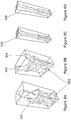
- Figure 4 shows a generally prismatic liner shape 260 in which the ends of the prism have been formed into a "half cone" shape 262.
- the base end of the shaped charge liner is formed into a lip member 264 which has a circular profile for convenient engagement with the perforator charge casing.
- the apex 230 of the liner of Figure 4 is a line rather than a point. It is noted that looking down the main liner axis 220 (from above the apex 230 end of the liner) it can be seen that the liner of Figure 4 demonstrates rotational symmetry (such that a 180° rotation, 2-fold symmetry will leave the liner unchanged) but does not demonstrate circular symmetry. In other words any angular rotation of the liner of Figure 4 , other than 180° or a multiple thereof, will not result in the liner appearing identical to the start position.
- Figure 5 shows a pyramidal shaped charge liner 270. Again the base 240 of the liner is formed into a lip member 264. Again, viewed from above the liner demonstrates rotational symmetry (4-fold rotational symmetry) but does not display circular symmetry.
- Figure 6 shows a shaped charge liner 280 that has a star-like cross section.
- the particular liner depicted in Figure 5 is a four pointed star but it is noted that the liner may be constructed as a five pointed, six pointed or an n-pointed star (where n is an integer).
- the base 240 of the shaped charge liner is formed into a similar lip member 264 to that of Figure 4 . Again, viewed from above the liner demonstrates rotational symmetry (4-fold rotational symmetry) but does not display circular symmetry.
- the liners (260, 270, 280) depicted in Figures 4 to 6 are therefore distinguished from known conical or hemispherical liners which exhibit circular symmetry.
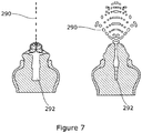
- Figure 7 shows a simulation of the shaped charge liner 260 of Figure 4 when fired from a perforator gun. It can be seen that the jet 290 of ejected material is dispersed into distinctive planes (the left hand and right hand images in Figure 7 show two perpendicular planes). It is also noted that the rear of the jet (the "slug" 292) is rectangular in shape.
- Figure 8 shows the simulated effects of the jet 290 of Figure 7 impacting the target arrangement 200 of Figure 3 . It can be seen that the jet 290 is predicted to penetrate through the well casing 202, the cement 204 and into the rock 206. It is noted that Figures 7 and 8 represent a shaped charge liner in accordance with Figure 4 . In this case the liner was fabricated from wrought copper but could also be pressed powder or even non-metallic or reactive.
- Figure 9a is a three dimensional representation of the predicted tunnel geometry 300 formed by the jet 290 of Figure 7 (liner 260 of Figure 4 ). It can be seen that the hole 302 in the backing rock is generally slot shaped (i.e. it has a rectilinear geometry). It is also noted that the hole in the well casing is also slot shaped
- Figure 9b shows the predicted tunnel geometry formed for a liner of Figure 4 fabricated from tungsten powder. It can be seen that the hole of Figure 9b is also slotted in shape but additionally has two offshoots 304 from the main hole 302 such that the overall jet shape is generally "Y" shaped. The two offshoots provide a mechanism for producing preferential fracture initiation sites in the rock formation.
- Figures 9c and 9d show the tunnels that result from copper liners according to Figures 6 and 5 respectively.
- the tunnel 306 formed in Figure 9c can be seen to be generally diamond shaped and the tunnel 308 formed in Figure 9d can be seen to be generally elliptically shaped.
- Variants of the liner 260 depicted in Figure 4 were then further tested using the in the laboratory tests using the charge design 310 shown in Figure 10 .
- the charge design of Figure 10 used in the laboratory tests comprised a steel charge holder 312 within which was held a main explosive charge of EDC 1(S) 314. One end 315 of the charge holder held the shaped charge liner under test. At the other end of the holder a booster pellet 316 (for initiating the main charge) was mounted so that it was in contact with (in communication with) the high/low voltage detonator 318.
- the further testing comprised changing the liner profile of the shaped charge liner of Figure 4 slightly in order to "tune" the performance of the liner upon detonation.
- Two different liner profiles were tested.
- Figure 11 shows a cross section through the liner 230 of Figure 4 . It is noted that an internal apex angle ⁇ is defined by the prism sides of the liner. The first liner tested had an internal angle of 50° and the second liner tested had an internal angle of 60° although the skilled person will appreciate that other angles could be used.
- a similar cross section would be apparent for the liners of Figures 5 and 6 , having an apex angle ⁇ .
- FIG. 12a shows the predicted tunnel profile for the EDC1 filled design of shaped charge liner for a 50° internal apex angle
- Figure 12b shows the predicted tunnel profile for the shaped charge liner for a 60° internal apex angle. It can be seen that the changed apex angle results in a slightly different tunnel profile.
- the primary tunnel 334 is more prominent compared to the offshoots 336.
- the primary tunnel 338 and offshoots 340 are of similar size.
- the liner of Figure 4 with an internal apex angle of 50° was fired into a target consistent with the arrangement of Figure 3 .
- a slot shaped tunnel 350 was created through the cement layer, through the well casing and with an initial incursion into the rock, as shown in the photograph of Figure 13 .
- the test firing was repeated with another liner of the same profile.
- Two further test firings were performed with a liner of the shape of Figure 4 with an internal apex angle of 60°. The results of the various firings are shown below in Table 1 which show the hole dimensions in each part of the target.
- the liner trials demonstrate that slot holes can be produced with a prismatic liner 260 with varying internal apex angles. The results are reproducible and also demonstrate that varying the apex angle alters the size of the resultant hole.
- holes produced in the steel plate 202 are approximately 10 times larger in cross section than holes produced from an equivalent standard perforator charge which are generally 12.5 mm in diameter (as defined in the JRC Shaped Charge Listing performance handbook).
- Figure 14a to 14d show the results of measuring the jet formation of the liners (firing rounds in Table 1) 1-4 tested above using a flash X-ray radiography set up.
- Figures 14a and 14b show orthogonal flash X-rays for the 50° liner design taken 25 ⁇ s after firing.
- Figures 14c and 14d show orthogonal flash X-rays for the 60° liner design taken 25 ⁇ s after firing.
- the X-rays all also show that the jet is a 'blade' shape in one plane and a narrow jet in the other plane and there is some evidence of the jet splitting. There is also a pronounced slug in the jet. The rounds were reproducible.
- Figures 15a to 15d correspond to Figures 14a to 14b and additionally show the results of computer modelling of the shape of the jet formed from the 50° and 60° liners. It can be seen that there is a good correspondence between simulation and experiment.
- Figures 3 to 15 show how, according to a first aspect of the present invention, the liner geometry can be customised such that desirable perforation tunnel geometric features are created, to order, within the well casing, cementation layer and rock strata.
- desirable features include (but are not limited to):-
- Tests presented above on the liner 260 variants depicted in Figure 4 indicated the effects of changing the internal apex angle of the liner. It is noted that additionally, or alternatively, the liner or charge configuration may be varied to produce a designer hole. These are listed below and can be used to customise the hole produced by the charge.
- a method of generating a library of shaped charge liners detailing the performance of such liners in different environmental conditions According to a yet further aspect of the present invention there is provided a method of optimising a shaped charge liner design for use in an oil/gas well perforator to form a desired hole shape in a rock formation.
- Figure 16a is a flow chart 400 that details the process of generating a library of shape charge liners. So the process is to select or calculate the type of hole required for the given strata, gun dimensions, perforator geometrical constraints and well conditions (Step 402 - receive desired hole "target" parameters and Step 404 - receive environmental parameters). One would then develop a bespoke charge design (Step 406) to produce a 'designer hole' based on advanced simulation techniques. As experience is gained this would be expanded into a library of charge configurations/designs suitable for a range of wells that the completion engineer could select for a given application. This library would evolve (Step 408) to encompass more relevant situations encountered by the completion engineer. Additional simulations (e.g.
- Figure 16b is a flow chart 410 that relates to the process of liner/charge optimisation.
- FIG. 17 An example of the data contained in such a library is shown in Figure 17 . It can be seen that four different liner types, A-D, are characterised (there may be, for example, prismatic, star shaped, pyramid, hexagonal liners). For each liner type the performance of different rock types (R1, R2, R3, R4) is detailed and the data on the hole produced includes the type of cross section and the depth that the jet produced by the liner penetrates into the rock around the oil well. This would also be repeated for a range of gun and well dimensions. It should be noted that it is unlikely that the charges can simply be scaled from one gun/well condition to another.
- the library may additionally include data on the effect of different liner materials on the performance of such liners (in which case each of the entries against each liner type in Figure 17 would be repeated for each potential liner material).
- Step 412 parameters relating to a desired hole to be formed in the rock adjacent to an oil/gas well are received.
- Such parameters may comprise the required hole depth and the general hole profile required (e.g. "slot like" cross section).
- Step 414 the received hole parameters are compared to the data contained within the library. It is noted that the performance of each liner within the library may be characterised for different rock types (e.g. sandstone, granite etc) and gun geometry, well conditions and additional constraints.
- the comparison of Step 414 would include filtering the data contained in the library to relate to the correct environment including rock type and strata conditions (i.e. the rock type that corresponds to the intended rock type that an oil/gas well is located in).
- Step 416 the shaped charge liner within the library that results in a hole that is closest to the desired hole shape is chosen.
- a parameter relating to the selected liner is varied.
- This parameter may be the liner material, the liner thickness, the depth of the liner (or the internal apex angle) or any other relevant parameter.
- Step 420 the performance of the modified liner is modelled.
- suitable modelling methods comprise the GRIM hydrocode package.
- Step 422 the hole produced by the modified liner design is compared again to the desired hole profile. Steps 418 and 420 may then be repeated until the liner performance shows no further improvement (or until the liner performance shows no appreciable improvement). In other words the optimisation method checks whether the modified liner performance has converged towards the desired hole shape.
- the resultant shaped charge liner design represents an optimised design that is suitable for use in the particular down-well environment that relates to the desired hole shape.
Landscapes
- Engineering & Computer Science (AREA)
- Geology (AREA)
- Life Sciences & Earth Sciences (AREA)
- Mining & Mineral Resources (AREA)
- General Engineering & Computer Science (AREA)
- Physics & Mathematics (AREA)
- Environmental & Geological Engineering (AREA)
- Fluid Mechanics (AREA)
- General Life Sciences & Earth Sciences (AREA)
- Geochemistry & Mineralogy (AREA)
- Manufacturing & Machinery (AREA)
- Earth Drilling (AREA)
- Drilling And Exploitation, And Mining Machines And Methods (AREA)
Claims (8)
- Verfahren zur Optimierung einer Hohlladungsauskleidungsausführung zur Verwendung in einem Öl-/Gas-Bohrlochperforator, um eine gewünschte Lochform in einer Gesteinsformation zu bilden, wobei das Verfahren das Vergleichen der gewünschten Lochform mit einer Bibliothek von bekannten Auskleidungsausführungen, wobei die Bibliothek Daten betreffend die Lochform umfasst, die durch jede Auskleidungsausführung in der Bibliothek gebildet wird;
das Auswählen der Auskleidungsausführung, die die Lochform erzeugt, die der gewünschten Lochform am nächsten kommt;
das Ändern von mindestens einem Parameter der ausgewählten Auskleidungsausführung, um eine modifizierte Auskleidungsausführung zu bilden;
das Modellieren der Lochform, die die modifizierte Auskeidungsausführung erzeugt;
das Wiederholen der Änderungs- und Modellierungsschritte, bis die Lochform der modifizierten Auskleidungsausführung zur gewünschten Lochform hin konvergiert, umfasst. - Verfahren nach Anspruch 1, wobei der Änderungsschritt das Ändern der Dicke der ausgewählten Auskleidungsausführung umfasst.
- Verfahren nach Anspruch 1 oder 2, wobei die ausgewählte Hohlladungsauskleidungsausführung einen internen Spitzenwinkel definiert und der Änderungsschritt das Ändern des internen Spitzenwinkels der ausgewählten Auskleidungsausführung umfasst.
- Verfahren nach einem der Ansprüche 1 bis 2, wobei der Änderungsschritt das Ändern des Auskleidungsmaterials der ausgewählten Auskleidungsausführung umfasst.
- Verfahren nach einem der Ansprüche 1 bis 4, ferner umfassend Ändern mehrerer Parameter der ausgewählten Auskleidungsausführung, wobei optional die mehreren Parameter parallel geändert werden, optional die mehreren Parameter sequenziell geändert werden.
- Verfahren nach einem der Ansprüche 1 bis 5, wobei die Bibliothek Daten für eine Vielzahl von Auskleidungsausführungen und die Lochform, die jede Auskleidung in einem Bereich unterschiedlicher Gesteinsschichten erzeugt, umfasst, optional wobei der Auswahlschritt das Filtern der Daten für die Vielzahl von Auskleidungsausführungen gegen die Gesteinszustände für eine bestimmte Bohrlochumgebung umfasst.
- Verfahren zum Erzeugen einer Bibliothek von Hohlladungsauskleidungen, die das Verhalten derartiger Auskleidungen in unterschiedlichen Umgebungsbedingungen detailliert beschreiben, wobei das Verfahren Folgendes umfasst: Empfangen von gewünschten Loch-Zielparametern;
Empfangen von Daten betreffend die Umgebungsbedingungen, unter denen die Hohlladungsauskleidung betrieben werden soll;
Modellieren der zugeschnittenen Hohlladungsauskleidung
Bestimmen der Lochparameter, die eine derartige zugeschnittene Auskleidung im Zusammenhang mit den Umgebungsbedingungen erzeugt, und Hinzufügen von Daten betreffend die Hohlladungsauskleidung und ihr Verhalten in eine Bibliothek. - Computerlesbares Medium, umfassend eine Computerprogramm, das angeordnet ist, um einen Computer so zu konfigurieren, dass er das Verfahren nach einem der Ansprüche 1 bis 7 implementiert.
Applications Claiming Priority (2)
| Application Number | Priority Date | Filing Date | Title |
|---|---|---|---|
| GBGB1222474.7A GB201222474D0 (en) | 2012-12-13 | 2012-12-13 | Shaped charge and method of modifying a shaped charge |
| PCT/EP2013/076578 WO2014091004A1 (en) | 2012-12-13 | 2013-12-13 | Shaped charge and method of modifying a shaped charge |
Publications (2)
| Publication Number | Publication Date |
|---|---|
| EP2932185A1 EP2932185A1 (de) | 2015-10-21 |
| EP2932185B1 true EP2932185B1 (de) | 2018-05-30 |
Family
ID=47630656
Family Applications (1)
| Application Number | Title | Priority Date | Filing Date |
|---|---|---|---|
| EP13803074.7A Revoked EP2932185B1 (de) | 2012-12-13 | 2013-12-13 | Verfahren zur modifizierung einer hohlladung |
Country Status (5)
| Country | Link |
|---|---|
| US (4) | US10533401B2 (de) |
| EP (1) | EP2932185B1 (de) |
| CA (2) | CA2933302C (de) |
| GB (3) | GB201222474D0 (de) |
| WO (1) | WO2014091004A1 (de) |
Cited By (1)
| Publication number | Priority date | Publication date | Assignee | Title |
|---|---|---|---|---|
| US20210072008A1 (en) * | 2018-11-27 | 2021-03-11 | Halliburton Energy Services, Inc. | Shaped charge effect measurement |
Families Citing this family (15)
| Publication number | Priority date | Publication date | Assignee | Title |
|---|---|---|---|---|
| GB201222474D0 (en) | 2012-12-13 | 2013-01-30 | Qinetiq Ltd | Shaped charge and method of modifying a shaped charge |
| US10184326B2 (en) * | 2014-06-17 | 2019-01-22 | Baker Hughes, A Ge Company Llc | Perforating system for hydraulic fracturing operations |
| WO2018231847A1 (en) * | 2017-06-12 | 2018-12-20 | Owen Oil Tools Lp | Limited penetration perforating methods for oilfield applications |
| CA3073997C (en) | 2017-09-14 | 2022-06-21 | DynaEnergetics Europe GmbH | Shaped charge liner, shaped charge for high temperature wellbore operations and method of perforating a wellbore using same |
| CN111971453A (zh) | 2017-11-29 | 2020-11-20 | 德力能欧洲有限公司 | 封闭构件和具有封闭构件的封装的开槽聚能射孔弹 |
| US10520286B2 (en) | 2018-04-06 | 2019-12-31 | Dynaenergetics Gmbh & Co. Kg | Inlay for shaped charge and method of use |
| US11053782B2 (en) | 2018-04-06 | 2021-07-06 | DynaEnergetics Europe GmbH | Perforating gun system and method of use |
| US11591885B2 (en) | 2018-05-31 | 2023-02-28 | DynaEnergetics Europe GmbH | Selective untethered drone string for downhole oil and gas wellbore operations |
| US12031417B2 (en) | 2018-05-31 | 2024-07-09 | DynaEnergetics Europe GmbH | Untethered drone string for downhole oil and gas wellbore operations |
| WO2019238410A1 (en) | 2018-06-11 | 2019-12-19 | Dynaenergetics Gmbh & Co. Kg | Contoured liner for a rectangular slotted shaped charge |
| USD981345S1 (en) * | 2020-11-12 | 2023-03-21 | DynaEnergetics Europe GmbH | Shaped charge casing |
| WO2022135749A1 (en) | 2020-12-21 | 2022-06-30 | DynaEnergetics Europe GmbH | Encapsulated shaped charge |
| WO2022148557A1 (en) | 2021-01-08 | 2022-07-14 | DynaEnergetics Europe GmbH | Perforating gun assembly and components |
| US12253339B2 (en) | 2021-10-25 | 2025-03-18 | DynaEnergetics Europe GmbH | Adapter and shaped charge apparatus for optimized perforation jet |
| US12312925B2 (en) | 2021-12-22 | 2025-05-27 | DynaEnergetics Europe GmbH | Manually oriented internal shaped charge alignment system and method of use |
Citations (5)
| Publication number | Priority date | Publication date | Assignee | Title |
|---|---|---|---|---|
| US3100445A (en) | 1959-01-14 | 1963-08-13 | Borg Warner | Shaped charge and method of firing the same |
| CA2196385A1 (en) | 1997-01-30 | 1998-07-30 | Norman Gerald Lussier | Shaped charge assembly system |
| US6283214B1 (en) | 1999-05-27 | 2001-09-04 | Schlumberger Technology Corp. | Optimum perforation design and technique to minimize sand intrusion |
| WO2009117548A1 (en) | 2008-03-19 | 2009-09-24 | Owen Oil Tools Lp | Devices and methods for perforating a wellbore |
| WO2012082186A1 (en) | 2010-12-17 | 2012-06-21 | Halliburton Energy Services, Inc. | Coupler compliance tuning for mitigating shock produced by well perforating |
Family Cites Families (47)
| Publication number | Priority date | Publication date | Assignee | Title |
|---|---|---|---|---|
| US2839997A (en) * | 1950-05-12 | 1958-06-24 | Joseph H Church | Shaped charges |
| US3726224A (en) * | 1950-08-23 | 1973-04-10 | Us Army | Fluted liners for shaped charges |
| US2935020A (en) * | 1953-08-07 | 1960-05-03 | Pan American Petroleum Corp | Apparatus for cutting holes in well casing |
| NL210985A (de) | 1956-01-04 | 1964-01-15 | ||
| US3255659A (en) * | 1961-12-13 | 1966-06-14 | Dresser Ind | Method of manufacturing shaped charge explosive with powdered metal liner |
| US3242987A (en) * | 1962-03-06 | 1966-03-29 | Schlumberger Well Surv Corp | Methods and apparatus for completing wells |
| DE977835C (de) * | 1964-09-09 | Messerschmitt Boelkow Blohm | Hohlladung zur Erzeugung schnittartiger Wirkungen | |
| US3251300A (en) * | 1965-06-24 | 1966-05-17 | Schlumberger Prospection | Shaped charge apparatus |
| US3371605A (en) | 1966-07-05 | 1968-03-05 | Robert E. Eckels | Shaped explosive charge |
| GB1237392A (en) * | 1967-12-15 | 1971-06-30 | Messerschmitt Boelkow Blohm | Improvements in explosive charges |
| FR2316847A5 (fr) | 1969-04-24 | 1977-01-28 | France Etat | Nouveau procede de generation d'eclats, adaptation de ce procede aux tetes militaires sol-air ou air-air |
| US4841864A (en) * | 1988-02-09 | 1989-06-27 | The United States Of America As Represented By The Secretary Of The Army | Controlled explosively formed penetrator |
| US4958569B1 (en) | 1990-03-26 | 1997-11-04 | Olin Corp | Wrought copper alloy-shaped charge liner |
| US5859383A (en) * | 1996-09-18 | 1999-01-12 | Davison; David K. | Electrically activated, metal-fueled explosive device |
| US6026750A (en) * | 1998-04-01 | 2000-02-22 | Alliant Techsystems Inc. | Shaped charge liner with integral initiation mechanism |
| US6305289B1 (en) * | 1998-09-30 | 2001-10-23 | Western Atlas International, Inc. | Shaped charge for large diameter perforations |
| US6634300B2 (en) * | 2000-05-20 | 2003-10-21 | Baker Hughes, Incorporated | Shaped charges having enhanced tungsten liners |
| CA2354883A1 (en) * | 2000-08-09 | 2002-02-09 | Steven L. Renfro | Thinned-skirt shaped-charge liner |
| GB2382122A (en) * | 2001-11-14 | 2003-05-21 | Qinetiq Ltd | Shaped charge liner |
| US6668726B2 (en) * | 2002-01-17 | 2003-12-30 | Innicor Subsurface Technologies Inc. | Shaped charge liner and process |
| US20030183113A1 (en) * | 2002-03-12 | 2003-10-02 | Barlow Darren R. | Shaped-charge liner with precursor liner |
| IL154247A0 (en) * | 2003-02-02 | 2004-03-28 | Rafael Armament Dev Authority | Double explosively-formed ring warhead |
| US6840178B2 (en) | 2003-02-21 | 2005-01-11 | Titan Specialties, Ltd. | Shaped charge liner |
| US6983698B1 (en) * | 2003-04-24 | 2006-01-10 | The United States Of America As Represented By The Secretary Of The Army | Shaped charge explosive device and method of making same |
| GB0323717D0 (en) * | 2003-10-10 | 2003-11-12 | Qinetiq Ltd | Improvements in and relating to oil well perforators |
| US6925924B2 (en) * | 2003-10-14 | 2005-08-09 | Molycorp Inc. | Method and apparatus to improve perforating effectiveness using a unique multiple point initiated shaped charge perforator |
| GB0425216D0 (en) | 2004-11-16 | 2004-12-15 | Qinetiq Ltd | Improvements in and relating to oil well perforators |
| US7600476B1 (en) * | 2006-03-24 | 2009-10-13 | The United States Of America As Represented By The Secretary Of The Army | Geometric/mechanical apparatus to improve well perforator performance |
| US20100000397A1 (en) * | 2006-04-17 | 2010-01-07 | Owen Oil Tools Lp | High Density Perforating Gun System Producing Reduced Debris |
| US20070240599A1 (en) * | 2006-04-17 | 2007-10-18 | Owen Oil Tools Lp | High density perforating gun system producing reduced debris |
| EP2100088A4 (de) * | 2006-12-20 | 2012-11-28 | James D Ruhlman | Bombe mit reduzierten kollateralschäden mit sicherungssystem mit hohlladung sowie herstellungssystem und -verfahren dafür |
| US8156871B2 (en) * | 2007-09-21 | 2012-04-17 | Schlumberger Technology Corporation | Liner for shaped charges |
| US8006621B1 (en) * | 2008-02-07 | 2011-08-30 | Cherry Christopher R | Linear explosive breaching apparatus and method |
| US8037829B1 (en) * | 2008-06-11 | 2011-10-18 | Raytheon Company | Reactive shaped charge, reactive liner, and method for target penetration using a reactive shaped charge |
| US8166882B2 (en) | 2009-06-23 | 2012-05-01 | Schlumberger Technology Corporation | Shaped charge liner with varying thickness |
| GB2503186B (en) * | 2009-11-25 | 2015-03-25 | Secr Defence | Shaped charge casing |
| GB2476994B (en) | 2010-01-18 | 2015-02-11 | Jet Physics Ltd | Linear shaped charge |
| US8381652B2 (en) * | 2010-03-09 | 2013-02-26 | Halliburton Energy Services, Inc. | Shaped charge liner comprised of reactive materials |
| US8375859B2 (en) | 2010-03-24 | 2013-02-19 | Southwest Research Institute | Shaped explosive charge |
| US8813651B1 (en) * | 2011-12-21 | 2014-08-26 | The United States Of America As Represented By The Secretary Of The Army | Method of making shaped charges and explosively formed projectiles |
| US9394767B2 (en) * | 2012-02-08 | 2016-07-19 | Hunting Titan, Inc. | Transient control of wellbore pressure |
| GB201222474D0 (en) * | 2012-12-13 | 2013-01-30 | Qinetiq Ltd | Shaped charge and method of modifying a shaped charge |
| BR112015016521A2 (pt) * | 2013-02-05 | 2017-07-11 | Halliburton Energy Services Inc | métodos de controlar a pressão dinâmica criada durante detonação de uma carga moldada utilizando uma substância |
| US10480295B2 (en) * | 2013-05-30 | 2019-11-19 | Halliburton Energy Services, Inc. | Jet perforating device for creating a wide diameter perforation |
| US9383176B2 (en) * | 2013-06-14 | 2016-07-05 | Schlumberger Technology Corporation | Shaped charge assembly system |
| US10267603B2 (en) * | 2017-07-25 | 2019-04-23 | Southwest Research Institute | Off-axis annular precision initiation charge |
| WO2020112089A1 (en) * | 2018-11-27 | 2020-06-04 | Halliburton Energy Services, Inc. | Shaped charge effect measurement |
-
2012
- 2012-12-13 GB GBGB1222474.7A patent/GB201222474D0/en not_active Ceased
-
2013
- 2013-12-13 CA CA2933302A patent/CA2933302C/en active Active
- 2013-12-13 CA CA3091618A patent/CA3091618A1/en active Pending
- 2013-12-13 US US14/651,829 patent/US10533401B2/en active Active
- 2013-12-13 GB GBGB2003896.4A patent/GB202003896D0/en not_active Ceased
- 2013-12-13 GB GB1322090.0A patent/GB2510482B/en not_active Expired - Fee Related
- 2013-12-13 WO PCT/EP2013/076578 patent/WO2014091004A1/en not_active Ceased
- 2013-12-13 EP EP13803074.7A patent/EP2932185B1/de not_active Revoked
-
2019
- 2019-12-05 US US16/704,524 patent/US11002118B2/en not_active Expired - Fee Related
-
2020
- 2020-05-13 US US15/930,939 patent/US11215039B2/en not_active Expired - Fee Related
-
2021
- 2021-04-13 US US17/229,093 patent/US11702912B2/en active Active
Patent Citations (5)
| Publication number | Priority date | Publication date | Assignee | Title |
|---|---|---|---|---|
| US3100445A (en) | 1959-01-14 | 1963-08-13 | Borg Warner | Shaped charge and method of firing the same |
| CA2196385A1 (en) | 1997-01-30 | 1998-07-30 | Norman Gerald Lussier | Shaped charge assembly system |
| US6283214B1 (en) | 1999-05-27 | 2001-09-04 | Schlumberger Technology Corp. | Optimum perforation design and technique to minimize sand intrusion |
| WO2009117548A1 (en) | 2008-03-19 | 2009-09-24 | Owen Oil Tools Lp | Devices and methods for perforating a wellbore |
| WO2012082186A1 (en) | 2010-12-17 | 2012-06-21 | Halliburton Energy Services, Inc. | Coupler compliance tuning for mitigating shock produced by well perforating |
Non-Patent Citations (13)
| Title |
|---|
| "Fundamentals of Shaped Charges", 1989, article WILLIAM P WALTERS: "Chapter 1 - 4", pages: 1 - 71, XP055576030 |
| "Introduction to API 19b Section IV testing on sandstone cores and shaped charge testing for 2'' and 2 1/8'' systems", DYNAENERGETICS, EWAPS, November 2012 (2012-11-01), pages 1 - 20, XP055576022 |
| .: ".", API DATA SHEET |
| 2011 MOSELEY WEBSITE |
| BAUMANN ET AL.: "Perforating Innovations-Shooting Holes in Performance Models", OILFIELD REVIEW, 2014, XP055576062 |
| CLINTON C. QUATTLEBAUM ET AL.: "SPE 159085 Optimising Perforating Charge Design for Stimulation", SPE, 2012, pages 1 - 13, XP055576008 |
| DAVID DAVISON ET AL.: "A HYDROCODE-DESIGNED WELL PERFORATOR WITH EXCEPTIONAL PERFORMANCE", 17TH INTERNATIONAL SYMPOSIUM ON BALLISTICS, March 1998 (1998-03-01), Midrand, South Africa, pages 1 - 9, XP055576002 |
| JRC DATA SHEET |
| LS-DYNA EXAMPLES MANUAL, March 1998 (1998-03-01) |
| LS-DYNA USER'S MANUAL, May 1999 (1999-05-01) |
| LS-OPT USER'S MANUAL, December 2010 (2010-12-01) |
| P.S. SMITH ET AL.: "SPE 38141 Improvements in Perforating Performance in High Compressive Strength Rocks", SPE, 1997, pages 1 - 6, XP055576014 |
| SANDIA: "Optimized Conical Shaped Charge Design Using the SCAP Code", SAND REPORT, September 1988 (1988-09-01), pages 1 - 87, XP055576053 |
Cited By (2)
| Publication number | Priority date | Publication date | Assignee | Title |
|---|---|---|---|---|
| US20210072008A1 (en) * | 2018-11-27 | 2021-03-11 | Halliburton Energy Services, Inc. | Shaped charge effect measurement |
| US11585646B2 (en) * | 2018-11-27 | 2023-02-21 | Halliburton Energy Services, Inc. | Shaped charge effect measurement |
Also Published As
| Publication number | Publication date |
|---|---|
| GB201322090D0 (en) | 2014-01-29 |
| GB201222474D0 (en) | 2013-01-30 |
| US11002118B2 (en) | 2021-05-11 |
| CA3091618A1 (en) | 2014-06-19 |
| GB2510482A (en) | 2014-08-06 |
| EP2932185A1 (de) | 2015-10-21 |
| GB2510482B (en) | 2020-05-13 |
| US20200277842A1 (en) | 2020-09-03 |
| CA2933302A1 (en) | 2014-06-19 |
| US20150316360A1 (en) | 2015-11-05 |
| WO2014091004A1 (en) | 2014-06-19 |
| US20200109615A1 (en) | 2020-04-09 |
| GB202003896D0 (en) | 2020-05-06 |
| US11215039B2 (en) | 2022-01-04 |
| CA2933302C (en) | 2021-01-12 |
| US11702912B2 (en) | 2023-07-18 |
| US20210230985A1 (en) | 2021-07-29 |
| US10533401B2 (en) | 2020-01-14 |
Similar Documents
| Publication | Publication Date | Title |
|---|---|---|
| US11702912B2 (en) | Shaped charge and method of modifying a shaped charge | |
| CN112434419B (zh) | 深层页岩气预应力干预的体积压裂方法 | |
| US11021936B2 (en) | Utilizing electrically actuated explosives downhole | |
| US10920557B2 (en) | Utilizing electrically actuated explosives downhole | |
| WO2017099717A1 (en) | Mapping fractures using micro-seismic events | |
| US12523107B2 (en) | Explosive downhole tools having improved wellbore conveyance and debris properties, methods of using the explosive downhole tools in a wellbore, and explosive units for explosive column tools | |
| US12392211B2 (en) | Explosive downhole tools having improved wellbore conveyance and debris properties, methods of using the explosive downhole tools in a wellbore, and explosive units for explosive column tools | |
| US20200018144A1 (en) | Charge based stimulation of adjacent wells to form interconnected fracture network and hydrocarbon production therefrom | |
| Halleck et al. | Penetration of shaped charges in stressed rock | |
| US20190040311A1 (en) | Methods for enhancing applications of electrically controlled propellants in subterranean formations | |
| Baumann et al. | Perforating Innovations–Shooting Holes in Performance Models | |
| US10613239B2 (en) | Propellant stimulation for measurement of transient pressure effects of the propellant | |
| Krilov et al. | Advanced well stimulation method applying a propellant based technology | |
| Norouzi et al. | Stress-dependent perforation in carbonate rocks: an experimental study | |
| US10961828B2 (en) | Utilizing electrically actuated explosives downhole | |
| Gladkikh et al. | Predicting depth of penetration of downhole perforators | |
| Hebda et al. | Numerical modelling of shaped charges with an elliptical liner | |
| WO2025193906A1 (en) | Explosive downhole tools having improved wellbore conveyance and debris properties, methods of using the explosive downhole tools in a wellbore, and explosive units for explosive column tools | |
| RU2659446C1 (ru) | Способ формирования щелевой полости любой конфигурации в скальном массиве с использованием параллельно сближенных шпуровых и скважинных зарядов | |
| Lee | Computational Solid Mechanics for Oil Well Perforator Design | |
| Aspiras et al. | Selection of Candidate Geothermal Wells for Deflagration | |
| Brinsden et al. | Energetics Applications for the Oil and Gas Industry |
Legal Events
| Date | Code | Title | Description |
|---|---|---|---|
| PUAI | Public reference made under article 153(3) epc to a published international application that has entered the european phase |
Free format text: ORIGINAL CODE: 0009012 |
|
| 17P | Request for examination filed |
Effective date: 20150710 |
|
| AK | Designated contracting states |
Kind code of ref document: A1 Designated state(s): AL AT BE BG CH CY CZ DE DK EE ES FI FR GB GR HR HU IE IS IT LI LT LU LV MC MK MT NL NO PL PT RO RS SE SI SK SM TR |
|
| AX | Request for extension of the european patent |
Extension state: BA ME |
|
| RIN1 | Information on inventor provided before grant (corrected) |
Inventor name: TOWNSLEY, RICHARD GORDON Inventor name: CHURCH, PHILIP DUNCAN Inventor name: HINTON, MICHAEL JOHN Inventor name: GOULD, PETER JOHN |
|
| DAX | Request for extension of the european patent (deleted) | ||
| STAA | Information on the status of an ep patent application or granted ep patent |
Free format text: STATUS: EXAMINATION IS IN PROGRESS |
|
| 17Q | First examination report despatched |
Effective date: 20170314 |
|
| REG | Reference to a national code |
Ref country code: DE Ref legal event code: R079 Ref document number: 602013038285 Country of ref document: DE Free format text: PREVIOUS MAIN CLASS: F42B0001028000 Ipc: E21B0043117000 |
|
| GRAP | Despatch of communication of intention to grant a patent |
Free format text: ORIGINAL CODE: EPIDOSNIGR1 |
|
| STAA | Information on the status of an ep patent application or granted ep patent |
Free format text: STATUS: GRANT OF PATENT IS INTENDED |
|
| RIC1 | Information provided on ipc code assigned before grant |
Ipc: F42B 1/036 20060101ALI20180118BHEP Ipc: E21B 43/117 20060101AFI20180118BHEP Ipc: F42B 1/028 20060101ALI20180118BHEP |
|
| INTG | Intention to grant announced |
Effective date: 20180209 |
|
| GRAS | Grant fee paid |
Free format text: ORIGINAL CODE: EPIDOSNIGR3 |
|
| GRAA | (expected) grant |
Free format text: ORIGINAL CODE: 0009210 |
|
| STAA | Information on the status of an ep patent application or granted ep patent |
Free format text: STATUS: THE PATENT HAS BEEN GRANTED |
|
| AK | Designated contracting states |
Kind code of ref document: B1 Designated state(s): AL AT BE BG CH CY CZ DE DK EE ES FI FR GB GR HR HU IE IS IT LI LT LU LV MC MK MT NL NO PL PT RO RS SE SI SK SM TR |
|
| REG | Reference to a national code |
Ref country code: GB Ref legal event code: FG4D |
|
| REG | Reference to a national code |
Ref country code: CH Ref legal event code: EP |
|
| REG | Reference to a national code |
Ref country code: AT Ref legal event code: REF Ref document number: 1003785 Country of ref document: AT Kind code of ref document: T Effective date: 20180615 |
|
| REG | Reference to a national code |
Ref country code: IE Ref legal event code: FG4D |
|
| REG | Reference to a national code |
Ref country code: DE Ref legal event code: R096 Ref document number: 602013038285 Country of ref document: DE |
|
| REG | Reference to a national code |
Ref country code: NL Ref legal event code: MP Effective date: 20180530 |
|
| REG | Reference to a national code |
Ref country code: LT Ref legal event code: MG4D |
|
| PG25 | Lapsed in a contracting state [announced via postgrant information from national office to epo] |
Ref country code: LT Free format text: LAPSE BECAUSE OF FAILURE TO SUBMIT A TRANSLATION OF THE DESCRIPTION OR TO PAY THE FEE WITHIN THE PRESCRIBED TIME-LIMIT Effective date: 20180530 Ref country code: CY Free format text: LAPSE BECAUSE OF FAILURE TO SUBMIT A TRANSLATION OF THE DESCRIPTION OR TO PAY THE FEE WITHIN THE PRESCRIBED TIME-LIMIT Effective date: 20180530 Ref country code: NO Free format text: LAPSE BECAUSE OF FAILURE TO SUBMIT A TRANSLATION OF THE DESCRIPTION OR TO PAY THE FEE WITHIN THE PRESCRIBED TIME-LIMIT Effective date: 20180830 Ref country code: BG Free format text: LAPSE BECAUSE OF FAILURE TO SUBMIT A TRANSLATION OF THE DESCRIPTION OR TO PAY THE FEE WITHIN THE PRESCRIBED TIME-LIMIT Effective date: 20180830 Ref country code: SE Free format text: LAPSE BECAUSE OF FAILURE TO SUBMIT A TRANSLATION OF THE DESCRIPTION OR TO PAY THE FEE WITHIN THE PRESCRIBED TIME-LIMIT Effective date: 20180530 Ref country code: FI Free format text: LAPSE BECAUSE OF FAILURE TO SUBMIT A TRANSLATION OF THE DESCRIPTION OR TO PAY THE FEE WITHIN THE PRESCRIBED TIME-LIMIT Effective date: 20180530 Ref country code: ES Free format text: LAPSE BECAUSE OF FAILURE TO SUBMIT A TRANSLATION OF THE DESCRIPTION OR TO PAY THE FEE WITHIN THE PRESCRIBED TIME-LIMIT Effective date: 20180530 |
|
| PG25 | Lapsed in a contracting state [announced via postgrant information from national office to epo] |
Ref country code: GR Free format text: LAPSE BECAUSE OF FAILURE TO SUBMIT A TRANSLATION OF THE DESCRIPTION OR TO PAY THE FEE WITHIN THE PRESCRIBED TIME-LIMIT Effective date: 20180831 Ref country code: HR Free format text: LAPSE BECAUSE OF FAILURE TO SUBMIT A TRANSLATION OF THE DESCRIPTION OR TO PAY THE FEE WITHIN THE PRESCRIBED TIME-LIMIT Effective date: 20180530 Ref country code: LV Free format text: LAPSE BECAUSE OF FAILURE TO SUBMIT A TRANSLATION OF THE DESCRIPTION OR TO PAY THE FEE WITHIN THE PRESCRIBED TIME-LIMIT Effective date: 20180530 Ref country code: RS Free format text: LAPSE BECAUSE OF FAILURE TO SUBMIT A TRANSLATION OF THE DESCRIPTION OR TO PAY THE FEE WITHIN THE PRESCRIBED TIME-LIMIT Effective date: 20180530 |
|
| REG | Reference to a national code |
Ref country code: AT Ref legal event code: MK05 Ref document number: 1003785 Country of ref document: AT Kind code of ref document: T Effective date: 20180530 |
|
| PG25 | Lapsed in a contracting state [announced via postgrant information from national office to epo] |
Ref country code: NL Free format text: LAPSE BECAUSE OF FAILURE TO SUBMIT A TRANSLATION OF THE DESCRIPTION OR TO PAY THE FEE WITHIN THE PRESCRIBED TIME-LIMIT Effective date: 20180530 |
|
| PG25 | Lapsed in a contracting state [announced via postgrant information from national office to epo] |
Ref country code: DK Free format text: LAPSE BECAUSE OF FAILURE TO SUBMIT A TRANSLATION OF THE DESCRIPTION OR TO PAY THE FEE WITHIN THE PRESCRIBED TIME-LIMIT Effective date: 20180530 Ref country code: EE Free format text: LAPSE BECAUSE OF FAILURE TO SUBMIT A TRANSLATION OF THE DESCRIPTION OR TO PAY THE FEE WITHIN THE PRESCRIBED TIME-LIMIT Effective date: 20180530 Ref country code: CZ Free format text: LAPSE BECAUSE OF FAILURE TO SUBMIT A TRANSLATION OF THE DESCRIPTION OR TO PAY THE FEE WITHIN THE PRESCRIBED TIME-LIMIT Effective date: 20180530 Ref country code: AT Free format text: LAPSE BECAUSE OF FAILURE TO SUBMIT A TRANSLATION OF THE DESCRIPTION OR TO PAY THE FEE WITHIN THE PRESCRIBED TIME-LIMIT Effective date: 20180530 Ref country code: SK Free format text: LAPSE BECAUSE OF FAILURE TO SUBMIT A TRANSLATION OF THE DESCRIPTION OR TO PAY THE FEE WITHIN THE PRESCRIBED TIME-LIMIT Effective date: 20180530 Ref country code: RO Free format text: LAPSE BECAUSE OF FAILURE TO SUBMIT A TRANSLATION OF THE DESCRIPTION OR TO PAY THE FEE WITHIN THE PRESCRIBED TIME-LIMIT Effective date: 20180530 Ref country code: PL Free format text: LAPSE BECAUSE OF FAILURE TO SUBMIT A TRANSLATION OF THE DESCRIPTION OR TO PAY THE FEE WITHIN THE PRESCRIBED TIME-LIMIT Effective date: 20180530 |
|
| PG25 | Lapsed in a contracting state [announced via postgrant information from national office to epo] |
Ref country code: IT Free format text: LAPSE BECAUSE OF FAILURE TO SUBMIT A TRANSLATION OF THE DESCRIPTION OR TO PAY THE FEE WITHIN THE PRESCRIBED TIME-LIMIT Effective date: 20180530 Ref country code: SM Free format text: LAPSE BECAUSE OF FAILURE TO SUBMIT A TRANSLATION OF THE DESCRIPTION OR TO PAY THE FEE WITHIN THE PRESCRIBED TIME-LIMIT Effective date: 20180530 |
|
| REG | Reference to a national code |
Ref country code: DE Ref legal event code: R026 Ref document number: 602013038285 Country of ref document: DE |
|
| PLBI | Opposition filed |
Free format text: ORIGINAL CODE: 0009260 |
|
| PLAX | Notice of opposition and request to file observation + time limit sent |
Free format text: ORIGINAL CODE: EPIDOSNOBS2 |
|
| 26 | Opposition filed |
Opponent name: DYNAENERGETICS GMBH & CO. KG Effective date: 20190228 |
|
| PG25 | Lapsed in a contracting state [announced via postgrant information from national office to epo] |
Ref country code: SI Free format text: LAPSE BECAUSE OF FAILURE TO SUBMIT A TRANSLATION OF THE DESCRIPTION OR TO PAY THE FEE WITHIN THE PRESCRIBED TIME-LIMIT Effective date: 20180530 |
|
| PLBB | Reply of patent proprietor to notice(s) of opposition received |
Free format text: ORIGINAL CODE: EPIDOSNOBS3 |
|
| REG | Reference to a national code |
Ref country code: CH Ref legal event code: PL |
|
| PG25 | Lapsed in a contracting state [announced via postgrant information from national office to epo] |
Ref country code: MC Free format text: LAPSE BECAUSE OF FAILURE TO SUBMIT A TRANSLATION OF THE DESCRIPTION OR TO PAY THE FEE WITHIN THE PRESCRIBED TIME-LIMIT Effective date: 20180530 Ref country code: LU Free format text: LAPSE BECAUSE OF NON-PAYMENT OF DUE FEES Effective date: 20181213 |
|
| REG | Reference to a national code |
Ref country code: IE Ref legal event code: MM4A |
|
| REG | Reference to a national code |
Ref country code: BE Ref legal event code: MM Effective date: 20181231 |
|
| PG25 | Lapsed in a contracting state [announced via postgrant information from national office to epo] |
Ref country code: IE Free format text: LAPSE BECAUSE OF NON-PAYMENT OF DUE FEES Effective date: 20181213 |
|
| PG25 | Lapsed in a contracting state [announced via postgrant information from national office to epo] |
Ref country code: AL Free format text: LAPSE BECAUSE OF FAILURE TO SUBMIT A TRANSLATION OF THE DESCRIPTION OR TO PAY THE FEE WITHIN THE PRESCRIBED TIME-LIMIT Effective date: 20180530 Ref country code: BE Free format text: LAPSE BECAUSE OF NON-PAYMENT OF DUE FEES Effective date: 20181231 |
|
| PG25 | Lapsed in a contracting state [announced via postgrant information from national office to epo] |
Ref country code: LI Free format text: LAPSE BECAUSE OF NON-PAYMENT OF DUE FEES Effective date: 20181231 Ref country code: CH Free format text: LAPSE BECAUSE OF NON-PAYMENT OF DUE FEES Effective date: 20181231 |
|
| PG25 | Lapsed in a contracting state [announced via postgrant information from national office to epo] |
Ref country code: MT Free format text: LAPSE BECAUSE OF NON-PAYMENT OF DUE FEES Effective date: 20181213 |
|
| PG25 | Lapsed in a contracting state [announced via postgrant information from national office to epo] |
Ref country code: TR Free format text: LAPSE BECAUSE OF FAILURE TO SUBMIT A TRANSLATION OF THE DESCRIPTION OR TO PAY THE FEE WITHIN THE PRESCRIBED TIME-LIMIT Effective date: 20180530 |
|
| PG25 | Lapsed in a contracting state [announced via postgrant information from national office to epo] |
Ref country code: PT Free format text: LAPSE BECAUSE OF FAILURE TO SUBMIT A TRANSLATION OF THE DESCRIPTION OR TO PAY THE FEE WITHIN THE PRESCRIBED TIME-LIMIT Effective date: 20180530 |
|
| PG25 | Lapsed in a contracting state [announced via postgrant information from national office to epo] |
Ref country code: HU Free format text: LAPSE BECAUSE OF FAILURE TO SUBMIT A TRANSLATION OF THE DESCRIPTION OR TO PAY THE FEE WITHIN THE PRESCRIBED TIME-LIMIT; INVALID AB INITIO Effective date: 20131213 Ref country code: MK Free format text: LAPSE BECAUSE OF NON-PAYMENT OF DUE FEES Effective date: 20180530 |
|
| PG25 | Lapsed in a contracting state [announced via postgrant information from national office to epo] |
Ref country code: IS Free format text: LAPSE BECAUSE OF FAILURE TO SUBMIT A TRANSLATION OF THE DESCRIPTION OR TO PAY THE FEE WITHIN THE PRESCRIBED TIME-LIMIT Effective date: 20180930 |
|
| PLAB | Opposition data, opponent's data or that of the opponent's representative modified |
Free format text: ORIGINAL CODE: 0009299OPPO |
|
| R26 | Opposition filed (corrected) |
Opponent name: DYNAENERGETICS GMBH & CO. KG Effective date: 20190228 |
|
| RDAF | Communication despatched that patent is revoked |
Free format text: ORIGINAL CODE: EPIDOSNREV1 |
|
| RDAD | Information modified related to despatch of communication that patent is revoked |
Free format text: ORIGINAL CODE: EPIDOSCREV1 |
|
| APBM | Appeal reference recorded |
Free format text: ORIGINAL CODE: EPIDOSNREFNO |
|
| APBP | Date of receipt of notice of appeal recorded |
Free format text: ORIGINAL CODE: EPIDOSNNOA2O |
|
| APAH | Appeal reference modified |
Free format text: ORIGINAL CODE: EPIDOSCREFNO |
|
| APBQ | Date of receipt of statement of grounds of appeal recorded |
Free format text: ORIGINAL CODE: EPIDOSNNOA3O |
|
| PGFP | Annual fee paid to national office [announced via postgrant information from national office to epo] |
Ref country code: GB Payment date: 20221227 Year of fee payment: 10 Ref country code: FR Payment date: 20221227 Year of fee payment: 10 |
|
| REG | Reference to a national code |
Ref country code: DE Ref legal event code: R103 Ref document number: 602013038285 Country of ref document: DE Ref country code: DE Ref legal event code: R064 Ref document number: 602013038285 Country of ref document: DE |
|
| APBU | Appeal procedure closed |
Free format text: ORIGINAL CODE: EPIDOSNNOA9O |
|
| RDAG | Patent revoked |
Free format text: ORIGINAL CODE: 0009271 |
|
| STAA | Information on the status of an ep patent application or granted ep patent |
Free format text: STATUS: PATENT REVOKED |
|
| PGFP | Annual fee paid to national office [announced via postgrant information from national office to epo] |
Ref country code: DE Payment date: 20221228 Year of fee payment: 10 |
|
| REG | Reference to a national code |
Ref country code: CH Ref legal event code: PL |
|
| 27W | Patent revoked |
Effective date: 20230517 |
|
| GBPR | Gb: patent revoked under art. 102 of the ep convention designating the uk as contracting state |
Effective date: 20230517 |