EP2931429B1 - Method for connecting components of a microfluidic flow cell - Google Patents
Method for connecting components of a microfluidic flow cell Download PDFInfo
- Publication number
- EP2931429B1 EP2931429B1 EP13836251.2A EP13836251A EP2931429B1 EP 2931429 B1 EP2931429 B1 EP 2931429B1 EP 13836251 A EP13836251 A EP 13836251A EP 2931429 B1 EP2931429 B1 EP 2931429B1
- Authority
- EP
- European Patent Office
- Prior art keywords
- gap
- flow cell
- gap space
- components
- solvent
- Prior art date
- Legal status (The legal status is an assumption and is not a legal conclusion. Google has not performed a legal analysis and makes no representation as to the accuracy of the status listed.)
- Active
Links
- 238000000034 method Methods 0.000 title claims description 30
- 239000000463 material Substances 0.000 claims description 57
- 239000002904 solvent Substances 0.000 claims description 30
- 239000004020 conductor Substances 0.000 claims description 15
- 230000008020 evaporation Effects 0.000 claims description 8
- 238000001704 evaporation Methods 0.000 claims description 8
- 229920003229 poly(methyl methacrylate) Polymers 0.000 claims description 6
- 239000004926 polymethyl methacrylate Substances 0.000 claims description 6
- 229920001871 amorphous plastic Polymers 0.000 claims description 5
- 230000008021 deposition Effects 0.000 claims 3
- 229920003023 plastic Polymers 0.000 description 33
- 239000004033 plastic Substances 0.000 description 33
- 239000000853 adhesive Substances 0.000 description 15
- 230000001070 adhesive effect Effects 0.000 description 15
- 239000012530 fluid Substances 0.000 description 10
- 239000011888 foil Substances 0.000 description 9
- 238000004519 manufacturing process Methods 0.000 description 9
- 230000005855 radiation Effects 0.000 description 6
- 239000000758 substrate Substances 0.000 description 6
- XUIMIQQOPSSXEZ-UHFFFAOYSA-N Silicon Chemical compound [Si] XUIMIQQOPSSXEZ-UHFFFAOYSA-N 0.000 description 5
- 239000011521 glass Substances 0.000 description 5
- 229910052710 silicon Inorganic materials 0.000 description 5
- 239000010703 silicon Substances 0.000 description 5
- 230000000694 effects Effects 0.000 description 4
- 238000005516 engineering process Methods 0.000 description 4
- 239000004065 semiconductor Substances 0.000 description 4
- XEKOWRVHYACXOJ-UHFFFAOYSA-N Ethyl acetate Chemical compound CCOC(C)=O XEKOWRVHYACXOJ-UHFFFAOYSA-N 0.000 description 3
- YXFVVABEGXRONW-UHFFFAOYSA-N Toluene Chemical compound CC1=CC=CC=C1 YXFVVABEGXRONW-UHFFFAOYSA-N 0.000 description 3
- 238000004026 adhesive bonding Methods 0.000 description 3
- 230000010354 integration Effects 0.000 description 3
- 238000003466 welding Methods 0.000 description 3
- CSCPPACGZOOCGX-UHFFFAOYSA-N Acetone Chemical compound CC(C)=O CSCPPACGZOOCGX-UHFFFAOYSA-N 0.000 description 2
- 230000002411 adverse Effects 0.000 description 2
- 239000012472 biological sample Substances 0.000 description 2
- 239000011248 coating agent Substances 0.000 description 2
- 238000000576 coating method Methods 0.000 description 2
- 238000004049 embossing Methods 0.000 description 2
- 230000005484 gravity Effects 0.000 description 2
- 238000001746 injection moulding Methods 0.000 description 2
- 230000013011 mating Effects 0.000 description 2
- 238000005259 measurement Methods 0.000 description 2
- 230000010076 replication Effects 0.000 description 2
- 231100000331 toxic Toxicity 0.000 description 2
- 230000002588 toxic effect Effects 0.000 description 2
- 238000007704 wet chemistry method Methods 0.000 description 2
- -1 are integrated Substances 0.000 description 1
- 230000015572 biosynthetic process Effects 0.000 description 1
- 238000009509 drug development Methods 0.000 description 1
- 238000007306 functionalization reaction Methods 0.000 description 1
- 230000001771 impaired effect Effects 0.000 description 1
- 239000007788 liquid Substances 0.000 description 1
- 239000002184 metal Substances 0.000 description 1
- 230000000750 progressive effect Effects 0.000 description 1
- 230000000630 rising effect Effects 0.000 description 1
- 239000000523 sample Substances 0.000 description 1
- 239000007787 solid Substances 0.000 description 1
- 239000000243 solution Substances 0.000 description 1
- 238000009736 wetting Methods 0.000 description 1
Images


Classifications
-
- B—PERFORMING OPERATIONS; TRANSPORTING
- B01—PHYSICAL OR CHEMICAL PROCESSES OR APPARATUS IN GENERAL
- B01L—CHEMICAL OR PHYSICAL LABORATORY APPARATUS FOR GENERAL USE
- B01L3/00—Containers or dishes for laboratory use, e.g. laboratory glassware; Droppers
- B01L3/50—Containers for the purpose of retaining a material to be analysed, e.g. test tubes
- B01L3/502—Containers for the purpose of retaining a material to be analysed, e.g. test tubes with fluid transport, e.g. in multi-compartment structures
- B01L3/5027—Containers for the purpose of retaining a material to be analysed, e.g. test tubes with fluid transport, e.g. in multi-compartment structures by integrated microfluidic structures, i.e. dimensions of channels and chambers are such that surface tension forces are important, e.g. lab-on-a-chip
- B01L3/502707—Containers for the purpose of retaining a material to be analysed, e.g. test tubes with fluid transport, e.g. in multi-compartment structures by integrated microfluidic structures, i.e. dimensions of channels and chambers are such that surface tension forces are important, e.g. lab-on-a-chip characterised by the manufacture of the container or its components
-
- B—PERFORMING OPERATIONS; TRANSPORTING
- B29—WORKING OF PLASTICS; WORKING OF SUBSTANCES IN A PLASTIC STATE IN GENERAL
- B29C—SHAPING OR JOINING OF PLASTICS; SHAPING OF MATERIAL IN A PLASTIC STATE, NOT OTHERWISE PROVIDED FOR; AFTER-TREATMENT OF THE SHAPED PRODUCTS, e.g. REPAIRING
- B29C65/00—Joining or sealing of preformed parts, e.g. welding of plastics materials; Apparatus therefor
- B29C65/48—Joining or sealing of preformed parts, e.g. welding of plastics materials; Apparatus therefor using adhesives, i.e. using supplementary joining material; solvent bonding
- B29C65/4895—Solvent bonding, i.e. the surfaces of the parts to be joined being treated with solvents, swelling or softening agents, without adhesives
-
- B—PERFORMING OPERATIONS; TRANSPORTING
- B29—WORKING OF PLASTICS; WORKING OF SUBSTANCES IN A PLASTIC STATE IN GENERAL
- B29C—SHAPING OR JOINING OF PLASTICS; SHAPING OF MATERIAL IN A PLASTIC STATE, NOT OTHERWISE PROVIDED FOR; AFTER-TREATMENT OF THE SHAPED PRODUCTS, e.g. REPAIRING
- B29C65/00—Joining or sealing of preformed parts, e.g. welding of plastics materials; Apparatus therefor
- B29C65/48—Joining or sealing of preformed parts, e.g. welding of plastics materials; Apparatus therefor using adhesives, i.e. using supplementary joining material; solvent bonding
- B29C65/52—Joining or sealing of preformed parts, e.g. welding of plastics materials; Apparatus therefor using adhesives, i.e. using supplementary joining material; solvent bonding characterised by the way of applying the adhesive
- B29C65/54—Joining or sealing of preformed parts, e.g. welding of plastics materials; Apparatus therefor using adhesives, i.e. using supplementary joining material; solvent bonding characterised by the way of applying the adhesive between pre-assembled parts
-
- B—PERFORMING OPERATIONS; TRANSPORTING
- B29—WORKING OF PLASTICS; WORKING OF SUBSTANCES IN A PLASTIC STATE IN GENERAL
- B29C—SHAPING OR JOINING OF PLASTICS; SHAPING OF MATERIAL IN A PLASTIC STATE, NOT OTHERWISE PROVIDED FOR; AFTER-TREATMENT OF THE SHAPED PRODUCTS, e.g. REPAIRING
- B29C66/00—General aspects of processes or apparatus for joining preformed parts
- B29C66/01—General aspects dealing with the joint area or with the area to be joined
- B29C66/05—Particular design of joint configurations
- B29C66/10—Particular design of joint configurations particular design of the joint cross-sections
- B29C66/12—Joint cross-sections combining only two joint-segments; Tongue and groove joints; Tenon and mortise joints; Stepped joint cross-sections
- B29C66/122—Joint cross-sections combining only two joint-segments, i.e. one of the parts to be joined comprising only two joint-segments in the joint cross-section
- B29C66/1222—Joint cross-sections combining only two joint-segments, i.e. one of the parts to be joined comprising only two joint-segments in the joint cross-section comprising at least a lapped joint-segment
-
- B—PERFORMING OPERATIONS; TRANSPORTING
- B29—WORKING OF PLASTICS; WORKING OF SUBSTANCES IN A PLASTIC STATE IN GENERAL
- B29C—SHAPING OR JOINING OF PLASTICS; SHAPING OF MATERIAL IN A PLASTIC STATE, NOT OTHERWISE PROVIDED FOR; AFTER-TREATMENT OF THE SHAPED PRODUCTS, e.g. REPAIRING
- B29C66/00—General aspects of processes or apparatus for joining preformed parts
- B29C66/01—General aspects dealing with the joint area or with the area to be joined
- B29C66/05—Particular design of joint configurations
- B29C66/10—Particular design of joint configurations particular design of the joint cross-sections
- B29C66/12—Joint cross-sections combining only two joint-segments; Tongue and groove joints; Tenon and mortise joints; Stepped joint cross-sections
- B29C66/122—Joint cross-sections combining only two joint-segments, i.e. one of the parts to be joined comprising only two joint-segments in the joint cross-section
- B29C66/1224—Joint cross-sections combining only two joint-segments, i.e. one of the parts to be joined comprising only two joint-segments in the joint cross-section comprising at least a butt joint-segment
-
- B—PERFORMING OPERATIONS; TRANSPORTING
- B29—WORKING OF PLASTICS; WORKING OF SUBSTANCES IN A PLASTIC STATE IN GENERAL
- B29C—SHAPING OR JOINING OF PLASTICS; SHAPING OF MATERIAL IN A PLASTIC STATE, NOT OTHERWISE PROVIDED FOR; AFTER-TREATMENT OF THE SHAPED PRODUCTS, e.g. REPAIRING
- B29C66/00—General aspects of processes or apparatus for joining preformed parts
- B29C66/40—General aspects of joining substantially flat articles, e.g. plates, sheets or web-like materials; Making flat seams in tubular or hollow articles; Joining single elements to substantially flat surfaces
- B29C66/47—Joining single elements to sheets, plates or other substantially flat surfaces
-
- B—PERFORMING OPERATIONS; TRANSPORTING
- B29—WORKING OF PLASTICS; WORKING OF SUBSTANCES IN A PLASTIC STATE IN GENERAL
- B29C—SHAPING OR JOINING OF PLASTICS; SHAPING OF MATERIAL IN A PLASTIC STATE, NOT OTHERWISE PROVIDED FOR; AFTER-TREATMENT OF THE SHAPED PRODUCTS, e.g. REPAIRING
- B29C66/00—General aspects of processes or apparatus for joining preformed parts
- B29C66/50—General aspects of joining tubular articles; General aspects of joining long products, i.e. bars or profiled elements; General aspects of joining single elements to tubular articles, hollow articles or bars; General aspects of joining several hollow-preforms to form hollow or tubular articles
- B29C66/51—Joining tubular articles, profiled elements or bars; Joining single elements to tubular articles, hollow articles or bars; Joining several hollow-preforms to form hollow or tubular articles
- B29C66/53—Joining single elements to tubular articles, hollow articles or bars
- B29C66/534—Joining single elements to open ends of tubular or hollow articles or to the ends of bars
- B29C66/5346—Joining single elements to open ends of tubular or hollow articles or to the ends of bars said single elements being substantially flat
-
- B—PERFORMING OPERATIONS; TRANSPORTING
- B29—WORKING OF PLASTICS; WORKING OF SUBSTANCES IN A PLASTIC STATE IN GENERAL
- B29C—SHAPING OR JOINING OF PLASTICS; SHAPING OF MATERIAL IN A PLASTIC STATE, NOT OTHERWISE PROVIDED FOR; AFTER-TREATMENT OF THE SHAPED PRODUCTS, e.g. REPAIRING
- B29C66/00—General aspects of processes or apparatus for joining preformed parts
- B29C66/50—General aspects of joining tubular articles; General aspects of joining long products, i.e. bars or profiled elements; General aspects of joining single elements to tubular articles, hollow articles or bars; General aspects of joining several hollow-preforms to form hollow or tubular articles
- B29C66/61—Joining from or joining on the inside
-
- B—PERFORMING OPERATIONS; TRANSPORTING
- B29—WORKING OF PLASTICS; WORKING OF SUBSTANCES IN A PLASTIC STATE IN GENERAL
- B29C—SHAPING OR JOINING OF PLASTICS; SHAPING OF MATERIAL IN A PLASTIC STATE, NOT OTHERWISE PROVIDED FOR; AFTER-TREATMENT OF THE SHAPED PRODUCTS, e.g. REPAIRING
- B29C66/00—General aspects of processes or apparatus for joining preformed parts
- B29C66/70—General aspects of processes or apparatus for joining preformed parts characterised by the composition, physical properties or the structure of the material of the parts to be joined; Joining with non-plastics material
- B29C66/73—General aspects of processes or apparatus for joining preformed parts characterised by the composition, physical properties or the structure of the material of the parts to be joined; Joining with non-plastics material characterised by the intensive physical properties of the material of the parts to be joined, by the optical properties of the material of the parts to be joined, by the extensive physical properties of the parts to be joined, by the state of the material of the parts to be joined or by the material of the parts to be joined being a thermoplastic or a thermoset
- B29C66/737—General aspects of processes or apparatus for joining preformed parts characterised by the composition, physical properties or the structure of the material of the parts to be joined; Joining with non-plastics material characterised by the intensive physical properties of the material of the parts to be joined, by the optical properties of the material of the parts to be joined, by the extensive physical properties of the parts to be joined, by the state of the material of the parts to be joined or by the material of the parts to be joined being a thermoplastic or a thermoset characterised by the state of the material of the parts to be joined
- B29C66/7377—General aspects of processes or apparatus for joining preformed parts characterised by the composition, physical properties or the structure of the material of the parts to be joined; Joining with non-plastics material characterised by the intensive physical properties of the material of the parts to be joined, by the optical properties of the material of the parts to be joined, by the extensive physical properties of the parts to be joined, by the state of the material of the parts to be joined or by the material of the parts to be joined being a thermoplastic or a thermoset characterised by the state of the material of the parts to be joined amorphous, semi-crystalline or crystalline
- B29C66/73771—General aspects of processes or apparatus for joining preformed parts characterised by the composition, physical properties or the structure of the material of the parts to be joined; Joining with non-plastics material characterised by the intensive physical properties of the material of the parts to be joined, by the optical properties of the material of the parts to be joined, by the extensive physical properties of the parts to be joined, by the state of the material of the parts to be joined or by the material of the parts to be joined being a thermoplastic or a thermoset characterised by the state of the material of the parts to be joined amorphous, semi-crystalline or crystalline the to-be-joined area of at least one of the parts to be joined being amorphous
-
- B—PERFORMING OPERATIONS; TRANSPORTING
- B01—PHYSICAL OR CHEMICAL PROCESSES OR APPARATUS IN GENERAL
- B01L—CHEMICAL OR PHYSICAL LABORATORY APPARATUS FOR GENERAL USE
- B01L2200/00—Solutions for specific problems relating to chemical or physical laboratory apparatus
- B01L2200/02—Adapting objects or devices to another
- B01L2200/026—Fluid interfacing between devices or objects, e.g. connectors, inlet details
- B01L2200/027—Fluid interfacing between devices or objects, e.g. connectors, inlet details for microfluidic devices
-
- B—PERFORMING OPERATIONS; TRANSPORTING
- B01—PHYSICAL OR CHEMICAL PROCESSES OR APPARATUS IN GENERAL
- B01L—CHEMICAL OR PHYSICAL LABORATORY APPARATUS FOR GENERAL USE
- B01L2200/00—Solutions for specific problems relating to chemical or physical laboratory apparatus
- B01L2200/06—Fluid handling related problems
- B01L2200/0689—Sealing
-
- B—PERFORMING OPERATIONS; TRANSPORTING
- B01—PHYSICAL OR CHEMICAL PROCESSES OR APPARATUS IN GENERAL
- B01L—CHEMICAL OR PHYSICAL LABORATORY APPARATUS FOR GENERAL USE
- B01L2200/00—Solutions for specific problems relating to chemical or physical laboratory apparatus
- B01L2200/12—Specific details about manufacturing devices
-
- B—PERFORMING OPERATIONS; TRANSPORTING
- B01—PHYSICAL OR CHEMICAL PROCESSES OR APPARATUS IN GENERAL
- B01L—CHEMICAL OR PHYSICAL LABORATORY APPARATUS FOR GENERAL USE
- B01L2300/00—Additional constructional details
- B01L2300/06—Auxiliary integrated devices, integrated components
- B01L2300/0627—Sensor or part of a sensor is integrated
- B01L2300/0636—Integrated biosensor, microarrays
-
- B—PERFORMING OPERATIONS; TRANSPORTING
- B01—PHYSICAL OR CHEMICAL PROCESSES OR APPARATUS IN GENERAL
- B01L—CHEMICAL OR PHYSICAL LABORATORY APPARATUS FOR GENERAL USE
- B01L2300/00—Additional constructional details
- B01L2300/06—Auxiliary integrated devices, integrated components
- B01L2300/0627—Sensor or part of a sensor is integrated
- B01L2300/0645—Electrodes
-
- B—PERFORMING OPERATIONS; TRANSPORTING
- B01—PHYSICAL OR CHEMICAL PROCESSES OR APPARATUS IN GENERAL
- B01L—CHEMICAL OR PHYSICAL LABORATORY APPARATUS FOR GENERAL USE
- B01L2300/00—Additional constructional details
- B01L2300/08—Geometry, shape and general structure
- B01L2300/0809—Geometry, shape and general structure rectangular shaped
- B01L2300/0816—Cards, e.g. flat sample carriers usually with flow in two horizontal directions
-
- B—PERFORMING OPERATIONS; TRANSPORTING
- B01—PHYSICAL OR CHEMICAL PROCESSES OR APPARATUS IN GENERAL
- B01L—CHEMICAL OR PHYSICAL LABORATORY APPARATUS FOR GENERAL USE
- B01L2300/00—Additional constructional details
- B01L2300/08—Geometry, shape and general structure
- B01L2300/0861—Configuration of multiple channels and/or chambers in a single devices
- B01L2300/0877—Flow chambers
-
- B—PERFORMING OPERATIONS; TRANSPORTING
- B01—PHYSICAL OR CHEMICAL PROCESSES OR APPARATUS IN GENERAL
- B01L—CHEMICAL OR PHYSICAL LABORATORY APPARATUS FOR GENERAL USE
- B01L2300/00—Additional constructional details
- B01L2300/12—Specific details about materials
-
- B—PERFORMING OPERATIONS; TRANSPORTING
- B29—WORKING OF PLASTICS; WORKING OF SUBSTANCES IN A PLASTIC STATE IN GENERAL
- B29C—SHAPING OR JOINING OF PLASTICS; SHAPING OF MATERIAL IN A PLASTIC STATE, NOT OTHERWISE PROVIDED FOR; AFTER-TREATMENT OF THE SHAPED PRODUCTS, e.g. REPAIRING
- B29C66/00—General aspects of processes or apparatus for joining preformed parts
- B29C66/70—General aspects of processes or apparatus for joining preformed parts characterised by the composition, physical properties or the structure of the material of the parts to be joined; Joining with non-plastics material
- B29C66/71—General aspects of processes or apparatus for joining preformed parts characterised by the composition, physical properties or the structure of the material of the parts to be joined; Joining with non-plastics material characterised by the composition of the plastics material of the parts to be joined
-
- B—PERFORMING OPERATIONS; TRANSPORTING
- B29—WORKING OF PLASTICS; WORKING OF SUBSTANCES IN A PLASTIC STATE IN GENERAL
- B29C—SHAPING OR JOINING OF PLASTICS; SHAPING OF MATERIAL IN A PLASTIC STATE, NOT OTHERWISE PROVIDED FOR; AFTER-TREATMENT OF THE SHAPED PRODUCTS, e.g. REPAIRING
- B29C66/00—General aspects of processes or apparatus for joining preformed parts
- B29C66/70—General aspects of processes or apparatus for joining preformed parts characterised by the composition, physical properties or the structure of the material of the parts to be joined; Joining with non-plastics material
- B29C66/73—General aspects of processes or apparatus for joining preformed parts characterised by the composition, physical properties or the structure of the material of the parts to be joined; Joining with non-plastics material characterised by the intensive physical properties of the material of the parts to be joined, by the optical properties of the material of the parts to be joined, by the extensive physical properties of the parts to be joined, by the state of the material of the parts to be joined or by the material of the parts to be joined being a thermoplastic or a thermoset
- B29C66/739—General aspects of processes or apparatus for joining preformed parts characterised by the composition, physical properties or the structure of the material of the parts to be joined; Joining with non-plastics material characterised by the intensive physical properties of the material of the parts to be joined, by the optical properties of the material of the parts to be joined, by the extensive physical properties of the parts to be joined, by the state of the material of the parts to be joined or by the material of the parts to be joined being a thermoplastic or a thermoset characterised by the material of the parts to be joined being a thermoplastic or a thermoset
- B29C66/7392—General aspects of processes or apparatus for joining preformed parts characterised by the composition, physical properties or the structure of the material of the parts to be joined; Joining with non-plastics material characterised by the intensive physical properties of the material of the parts to be joined, by the optical properties of the material of the parts to be joined, by the extensive physical properties of the parts to be joined, by the state of the material of the parts to be joined or by the material of the parts to be joined being a thermoplastic or a thermoset characterised by the material of the parts to be joined being a thermoplastic or a thermoset characterised by the material of at least one of the parts being a thermoplastic
-
- B—PERFORMING OPERATIONS; TRANSPORTING
- B29—WORKING OF PLASTICS; WORKING OF SUBSTANCES IN A PLASTIC STATE IN GENERAL
- B29L—INDEXING SCHEME ASSOCIATED WITH SUBCLASS B29C, RELATING TO PARTICULAR ARTICLES
- B29L2022/00—Hollow articles
-
- B—PERFORMING OPERATIONS; TRANSPORTING
- B29—WORKING OF PLASTICS; WORKING OF SUBSTANCES IN A PLASTIC STATE IN GENERAL
- B29L—INDEXING SCHEME ASSOCIATED WITH SUBCLASS B29C, RELATING TO PARTICULAR ARTICLES
- B29L2031/00—Other particular articles
- B29L2031/756—Microarticles, nanoarticles
Definitions
- the invention relates to a method for connecting components of a microfluidic flow cell, in particular for integrating components into a carrier structure of the flow cell, a gap space with a gap base limiting the gap depth being formed between the components to be connected.
- the invention further relates to a flow cell according to claim 5 produced by the method according to the invention.
- flow cells such as those used in medical analytics and diagnostics, biochemistry and molecular biology as well as drug development, and which have a plastic carrier structure into which functional components, in particular sensors made of silicon, are integrated , glass or metal are integrated.
- Such flow cells are subject to a trend towards progressive miniaturization and increasing complexity of their functions, so that such flow cells are now referred to as lab-on-chip.
- Processes from semiconductor technology are used to produce such flow cells, in particular for the microstructuring of glass or silicon substrates. This results in high material costs, especially in the manufacture of complex flow cells.
- a second production technique used is based on replication processes, e.g. injection molding or embossing processes. This means that substrates made of plastic, such as PMMA, PC, PP or COC, can be produced inexpensively, the surfaces of which can be modified and/or functionalized using plasma coating or wet-chemical processes. Adhesive methods, but also laser welding methods can be used to assemble such substrates.
- a disadvantage is that the aspect ratios that can be achieved in the latter way are significantly lower than in the case of semiconductor technology processes.
- the third disadvantage is the adhesive material, which comes into direct contact with the fluids to be examined. As a result, incorrect measurements can occur. Toxic effects on biological sample material cannot be ruled out either.
- Another disadvantage is that such adhesive materials have a comparatively high viscosity and low wettability, which means that such an adhesive does not fill an assembly gap by itself, ie not capillary, and has to be transported into the assembly gap with great effort.
- a method of the type mentioned can be the U.S. 7,001,572 B1 as well as the WO 2012/004 296 A1 remove. Gap spaces are formed between components to be connected to one another, which gaps are filled with an adhesive, the adhesive then curing.
- the invention is based on the object of creating a new method of the type mentioned at the outset, which enables components of a flow cell to be connected with increased precision and manufacturing reliability.
- the method according to the invention is characterized in that the gap space is filled with a solvent and the filled-in solvent dissolves material from at least one of the components delimiting the gap space, with the dissolved material in the course of evaporation of the solvent producing a connection between the Components deposited in the direction of the gap bottom and fills the gap space in its width completely and partially in its height and that several filling and evaporation / settling cycles are carried out to successively fill the gap space.
- such a solvent can quickly penetrate into very narrow assembly gaps by capillary action, which enables high precision in the mutual positioning of the components to be connected to one another.
- the solvent filled into the gap space can contain material dissolved therein for connecting the components from the outset, which is identical to the material of at least one of the components to be connected.
- the proportion by volume of the filling material is only 0.1 to 5% of the proportion by volume of the solvent so as not to limit its flowability too much.
- the assembly gap is at least partially filled by the material, which has solidified again after the solvent has evaporated, and a fluid-tight, firm connection is thus established between the components. Since the material corresponds to the material of one of the components, a practically one-piece connection of the filling with this component results, in particular for amorphous plastic material.
- the material can settle under the influence of gravity, i.e. in this case the gap space must be closed at the bottom.
- the settling of the material could be controlled by inertial forces, particularly centrifugal force.
- the filling of the gap space with material that settles can be influenced by setting the temperature that is decisive for evaporation. Additionally or alternatively, e.g. when using a centrifuge, the size of the force decisive for the settling of the material could also be controlled.
- the material mentioned is preferably an amorphous plastic, e.g. PMMA, PC, PS, COC or COP.
- the component is arranged in a pocket of the support structure and the gap space is designed as an annular gap that surrounds the component and is open on one axial side.
- the component In the pocket of the carrier structure, the component can rest against an annular shoulder that closes off the gap space on its other axial side, or a bottom of the pocket.
- the annular shoulder is formed by a perforated foil connected to the carrier structure.
- the annular shoulder or the pocket base has a structured surface such that a gap space area expanding the gap space is formed between the support structure and the component lying against the annular shoulder or the pocket base.
- the component can advantageously also be connected to the carrier structure in a fluid-tight manner in the region of the annular shoulder by means of offset material.
- the component has a functionalized surface on its side facing the annular shoulder. This functionalization, which is located close to the connection, is not impaired by the type of connection according to the invention.
- One of the components to be connected can additionally have one or more channel structures open on one side and/or reservoirs which connect a location for introducing the solvent to the annular gap or serve as an overflow space to accommodate solvent that exceeds the volume of the gap to be filled. In this way, the solvent can be introduced with comparatively large dosing tolerances.
- the microfluidic flow cell shown in part includes a plate-shaped support structure 1, which is preferably made of an amorphous plastic, such as PMMA, PC, PS, COC or COP.
- a microcomponent 3, in the example shown in the basic form of a circular disk or square plate, is arranged in a pocket 2 of the carrier structure 1 can be functionalized in different ways.
- the microcomponent 3 rests against an annular shoulder 4 of the pocket 2 that otherwise runs through the carrier structure 1 .
- An annular gap 5 formed between the carrier structure 1 and the microcomponent 3 is open on its one axial side and closed on its other axial side by the annular shoulder 4 of the carrier structure 1 .
- the gap width 3 of the annular gap 5 is typically between 0.01 and 0.1 mm.
- the annular gap 5 is partially filled with plastic material 6.
- FIG. 1b The width of the annular gap 5 bridging the plastic material 6 agrees with the Material match, from which the support structure 1 consists. It has settled out during the evaporation of a solvent 7 filled into the annular gap according to FIG. 1a, with the annular gap 5 being filled.
- the solvent 7 dissolves the carrier structure 1 so that the plastic material 6 deposited from the evaporated solution is at least partially material that has been removed from the carrier structure 1 . However, such material can already be dissolved in the solvent 7 filled into the annular gap 5 from the outset.
- solvents can be used, e.g. acetone-based solvent for PMMA plastic, ethyl acetate-based solvent for PC plastic and toluene-based solvent for COC plastic.
- the contact angles between such solvents and the plastic material of the support structure are typically below 10°, so that very fine gaps can be filled by capillary action.
- the plastic material 6 that settles in the annular gap 5 during the evaporation of the solvent 7 under the influence of gravity forms a bridge that closes the annular gap between the carrier structure 1 and the microcomponent 3 in a fluid-tight manner, through which a mechanically strong connection is also established between the components mentioned.
- the amorphous plastic material that settles forms a practically one-piece connection with the adjacent plastic of the support structure.
- the annular shoulder 4 has such a surface structure 8 that an angled gap area, continuing the annular gap 5, is formed, into which the solvent 7 can penetrate and which can be filled with resolidified plastic material 6.
- the capillary filling of the annular gap by the solvent is stopped at the inner edge of the annular shoulder 4 due to the abrupt interruption of the capillary effect, so that no solvent outside the annular shoulder 4 wets the underside of the microcomponent.
- a fluid-tight connection between the microcomponent 3 and the carrier structure 1 is also created in the area of the annular shoulder 4.
- a surface structure 8 suitable for forming such a gap widening can be a have defined roughness, grooves, webs and/or local, for example cylindrical elevations, the end faces of which then form the bearing surface for the microcomponent.
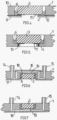
- the annular shoulder 4 accommodating the microcomponent 3 is formed by a perforated film 9 .
- the foil 9 together with a plastic plate 10 forms the carrier structure 1 and is glued or welded to the plastic plate 10 .
- a connection between the microcomponent 3 and the plastic plate 10 produced by offset plastic material 6 also stabilizes the foil 9 perforated to produce the annular shoulder 4. Due to the low height of the foil 9, it advantageously does not occur in the area of the surface of the microcomponent 3 adjoining the foil 9 to a dead volume, which could possibly have a negative effect on the examination of a fluid flowing past the microcomponent 3 .
- the film thickness is preferably between 0.01 and 0.2 mm.
- the foil 9 can be detachably connected to the microcomponent 3 .
- Adhesive foils or tapes, for example, are suitable for the connection. These can be removed again after the annular gap 5 has been filled with the plastic material 6 .
- a in 4 The exemplary embodiment shown differs from the previous exemplary embodiment in that the microcomponent 3 is connected to conductor tracks 11 which are in contact with conductor tracks 12 which are fed between the foil 9 and the plastic plate 10 .
- the width of the conductor tracks can be between 0.01 and 1 mm, their height between 0.01 and 10 ⁇ m.
- annular shoulder 4 is again formed in one piece with the rest of the support structure 1 and conductor tracks 11 connected to the microcomponent 3 are electrically in contact with conductor pins 13 which extend perpendicularly to the conductor tracks 11 through the annular shoulder 4 .
- the solid connection made by deposed plastic material 6 between the Microcomponent 3 and the support structure 1 also stabilizes the electrical contact between the conductor tracks 11 and conductor pins 13.
- a fluid channel 18 is formed in the support structure 1 and extends between connections 14 , 15 and is partially delimited by foils 16 and 17 .
- the fluid channel 18 leads past a functionalized surface 19 of the microcomponent 3 integrated into the carrier structure 1 by means of deposited plastic material 6 .
- a fluid channel 18 extends through a passage 20 of the microcomponent 3, also in the embodiment of FIG 9 , where the microcomponent 3 to 8 installed in the reverse position.
- a flow cell to be operated in the vertical position shown, having a supporting structure 1 and a further supporting structure 1', which is connected to the supporting structure 1 via a film 21, for example by means of gluing or welding.
- An inlet 22 on the support structure 1′ is connected to a channel 23, which leads to a microcomponent 3 with a functionalized surface 19, possibly via a plurality of fluid treatment and fluid processing stations (not shown). Fluid filled in through the inlet 22 rises in the channel 23 , with displaced air being able to escape through a vent opening 24 .
- the microcomponent 3 integrated into the carrier structure 1 by the deposited plastic material 6 is under increased fluid pressure, so that particularly high demands are made on the tightness of the integration.
Description
Die Erfindung betrifft gemäß Oberbegriff des Anspruchs 1 ein Verfahren zur Verbindung von Komponenten einer mikrofluidischen Flusszelle, insbesondere zur Einbindung von Bauteilen in eine Trägerstruktur der Flusszelle, wobei zwischen den zu verbindenden Komponenten ein Spaltraum mit einem die Spalttiefe begrenzenden Spaltboden gebildet wird.According to the preamble of claim 1, the invention relates to a method for connecting components of a microfluidic flow cell, in particular for integrating components into a carrier structure of the flow cell, a gap space with a gap base limiting the gap depth being formed between the components to be connected.
Die Erfindung betrifft ferner eine nach dem erfindungsgemäßen Verfahren hergestellte Flusszelle gemäß Anspruch 5.The invention further relates to a flow cell according to claim 5 produced by the method according to the invention.
Hauptanwendungsgebiet für das in Betracht stehende Verfahren ist die Herstellung von Flusszellen, wie sie z.B. in der medizinischen Analytik und Diagnostik, der Biochemie und der Molekularbiologie sowie der Medikamentenentwicklung zum Einsatz kommen und die eine Trägerstruktur aus Kunststoff aufweisen, in die Funktionsbauteile, insbesondere Sensoren aus Silizium, Glas oder Metall eingebunden sind. Derartige Flusszellen unterliegen einem Trend zu fortschreitender Miniaturisierung und zunehmender Komplexität ihrer Funktionen, so dass solche Flusszellen inzwischen als lab-on-chip bezeichnet werden.The main area of application for the process under consideration is the production of flow cells, such as those used in medical analytics and diagnostics, biochemistry and molecular biology as well as drug development, and which have a plastic carrier structure into which functional components, in particular sensors made of silicon, are integrated , glass or metal are integrated. Such flow cells are subject to a trend towards progressive miniaturization and increasing complexity of their functions, so that such flow cells are now referred to as lab-on-chip.
Bei der Herstellung solcher miniaturisierten Flusszellen müssen Funktionsstrukturen mit Abmessungen von wenigen 10 µm bis zu einigen 100 µm erzeugt werden. In diesen Funktionsstrukturen spielen Oberflächeneigenschaften eine dominante Rolle, z.B. im Hinblick auf die kapillare Befüllung von Kanälen und Probenkammern. Ferner sind Montagetechniken erforderlich, die ein flüssigkeitsdichtes und druckstabiles Verschließen von Mikrokammern und Kanälen und insbesondere die Bildung geschlossener mikrofluidischer Netzwerke erlauben. Solche Flusszellen kostengünstig in großen Stückzahlen zu produzieren, um sie beispielsweise in der medizinischen Diagnostik einsetzen zu können, erfordert hohen Aufwand.In the production of such miniaturized flow cells, functional structures with dimensions of a few 10 µm to several 100 µm must be created. In these functional structures, surface properties play a dominant role, for example with regard to the capillary filling of channels and sample chambers. Furthermore, assembly techniques are required that allow a liquid-tight and pressure-resistant closure of microchambers and channels and in particular the formation of closed microfluidic networks. Producing such flow cells in large quantities at low cost, for example to be able to use them in medical diagnostics, requires a great deal of effort.
Zur Herstellung solcher Flusszellen werden zum einen Verfahren der Halbleitertechnik eingesetzt, insbesondere zur Mikrostrukturierung von Glas- oder Siliziumsubstraten. Vor allem bei der Herstellung komplexer Flusszellen ergeben sich dabei hohe Materialkosten. Eine zweite verwendete Produktionstechnik basiert auf Replikationsverfahren, z.B. Spritzgieß- oder Prägeverfahren. Hierdurch lassen sich kostengünstig Substrate aus Kunststoff, wie z.B. aus PMMA, PC, PP oder COC herstellen, deren Oberflächen mittels Plasmabeschichtung oder nasschemischer Verfahren modifiziert oder/und funktionalisiert werden können. Zur Montage solcher Substrate lassen sich Klebeverfahren, aber auch Laserschweißverfahren einsetzen. Nachteilig sind die auf letztere Weise realisierbaren Aspektverhältnisse deutlich geringer als bei den Verfahren der Halbleitertechnik.Processes from semiconductor technology are used to produce such flow cells, in particular for the microstructuring of glass or silicon substrates. This results in high material costs, especially in the manufacture of complex flow cells. A second production technique used is based on replication processes, e.g. injection molding or embossing processes. This means that substrates made of plastic, such as PMMA, PC, PP or COC, can be produced inexpensively, the surfaces of which can be modified and/or functionalized using plasma coating or wet-chemical processes. Adhesive methods, but also laser welding methods can be used to assemble such substrates. A disadvantage is that the aspect ratios that can be achieved in the latter way are significantly lower than in the case of semiconductor technology processes.
Aus der
Aus den
Ein Verfahren der eingangs erwähnten Art lässt sich der
Der Erfindung liegt die Aufgabe zugrunde, ein neues Verfahren der eingangs erwähnten Art zu schaffen, das Verbindungen von Komponenten einer Flusszelle mit erhöhter Präzision und Fertigungssicherheit ermöglicht.The invention is based on the object of creating a new method of the type mentioned at the outset, which enables components of a flow cell to be connected with increased precision and manufacturing reliability.
Diese Aufgabe wird mit den Merkmalen des Anspruchs 1 gelöst.This object is achieved with the features of claim 1.
Das Verfahren nach der Erfindung ist dadurch gekennzeichnet, dass der Spaltraum mit einem Lösungsmittel gefüllt und durch das eingefüllte Lösungsmittel Material von wenigstens einer der den Spaltraum begrenzenden Komponenten gelöst wird, wobei sich das gelöste Material im Zuge einer Verdunstung des Lösungsmittels unter Herstellung einer Verbindung zwischen den Komponenten in Richtung zu dem Spaltboden absetzt und den Spaltraum in seiner Breite vollständig und in seiner Höhe teilweise auffüllt und dass zur sukzessiven Auffüllung des Spaltraums mehrere Einfüll- und Verdunstungs-/Absetzzyklen durchgeführt werden.The method according to the invention is characterized in that the gap space is filled with a solvent and the filled-in solvent dissolves material from at least one of the components delimiting the gap space, with the dissolved material in the course of evaporation of the solvent producing a connection between the Components deposited in the direction of the gap bottom and fills the gap space in its width completely and partially in its height and that several filling and evaporation / settling cycles are carried out to successively fill the gap space.
Vorteilhaft kann ein solches Lösungsmittel aufgrund seiner guten Benetzungseigenschaften schnell durch Kapillarwirkung in sehr enge Montagespalte eindringen, was eine hohe Präzision der gegenseitigen Positionierung der miteinander zu verbindenden Komponenten ermöglicht.Advantageously, due to its good wetting properties, such a solvent can quickly penetrate into very narrow assembly gaps by capillary action, which enables high precision in the mutual positioning of the components to be connected to one another.
Zum Füllen größerer Spalte kann das in den Spaltraum eingefüllte Lösungsmittel von vornherein darin aufgelöstes Material zur Verbindung der Komponenten enthalten, welches mit dem Material von wenigstens einer der zu verbindenden Komponenten identisch ist. Dabei beträgt der Volumenanteil des Füllmaterials nur 0,1 bis 5% des Volumenanteils des Lösungsmittels, um dessen Fließfähigkeit nicht zu stark einzuschränken.In order to fill larger gaps, the solvent filled into the gap space can contain material dissolved therein for connecting the components from the outset, which is identical to the material of at least one of the components to be connected. The proportion by volume of the filling material is only 0.1 to 5% of the proportion by volume of the solvent so as not to limit its flowability too much.
In jedem Fall wird der Montagespalt durch das nach Verdunsten des Lösungsmittels wieder verfestigte Material wenigstens teilweise aufgefüllt und so eine fluiddichte feste Verbindung zwischen den Komponenten hergestellt. Da das Material mit dem Material einer der Komponenten übereinstimmt, ergibt sich, insbesondere für amorphes Kunststoffmaterial eine praktisch einstückige Verbindung der Füllung mit dieser Komponente.In any case, the assembly gap is at least partially filled by the material, which has solidified again after the solvent has evaporated, and a fluid-tight, firm connection is thus established between the components. Since the material corresponds to the material of one of the components, a practically one-piece connection of the filling with this component results, in particular for amorphous plastic material.
Das Material kann sich unter dem Einfluss der Schwerkraft absetzen, d.h. dass der Spaltraum in diesem Fall nach unten abgeschlossen sein muss. Alternativ oder zusätzlich könnte das Absetzen des Materials durch Trägheitskräfte gesteuert werden, insbesondere durch eine Zentrifugalkraft.The material can settle under the influence of gravity, i.e. in this case the gap space must be closed at the bottom. Alternatively or additionally, the settling of the material could be controlled by inertial forces, particularly centrifugal force.
Das Auffüllen des Spaltraums mit sich absetzendem Material kann durch Einstellung der für die Verdunstung maßgebenden Temperatur beeinflusst werden. Zusätzlich oder alternativ ließe sich, z.B. bei Verwendung einer Zentrifuge, auch die Größe der für das Absetzen des Materials maßgebenden Kraft steuern.The filling of the gap space with material that settles can be influenced by setting the temperature that is decisive for evaporation. Additionally or alternatively, e.g. when using a centrifuge, the size of the force decisive for the settling of the material could also be controlled.
Bei dem genannten, ggf. wenigstens eine der Komponenten bildenden Material handelt es sich vorzugsweise um einen amorphen Kunststoff, z.B. PMMA, PC, PS, COC oder COP.The material mentioned, possibly forming at least one of the components, is preferably an amorphous plastic, e.g. PMMA, PC, PS, COC or COP.
In einer zweckmäßigen Ausführungsform der nach dem Verfahren hergestellten Flusszelle ist das Bauteil in einer Tasche der Trägerstruktur angeordnet und der Spaltraum als das Bauteil umgebender, zu einer axialen Seite hin offener Ringspalt ausgebildet.In an expedient embodiment of the flow cell produced according to the method, the component is arranged in a pocket of the support structure and the gap space is designed as an annular gap that surrounds the component and is open on one axial side.
Das Bauteil kann in der Tasche der Trägerstruktur gegen eine den Spaltraum auf dessen anderer axialen Seite abschließende Ringschulter oder einen Boden der Tasche anliegen.In the pocket of the carrier structure, the component can rest against an annular shoulder that closes off the gap space on its other axial side, or a bottom of the pocket.
Die Ringschulter ist in einer Ausführungsform durch eine mit der Trägerstruktur verbundene gelochte Folie gebildet.In one embodiment, the annular shoulder is formed by a perforated foil connected to the carrier structure.
In weiterer Ausgestaltung der Erfindung weist die Ringschulter oder der Taschenboden eine strukturierte Oberfläche derart auf, dass zwischen der Trägerstruktur und dem gegen die Ringschulter oder den Taschenboden anliegenden Bauteil ein den Spaltraum erweiternder Spaltraumbereich gebildet ist. Vorteilhaft lässt sich das Bauteil auf diese Weise auch im Bereich der Ringschulter mit der Trägerstruktur fluiddicht durch abgesetztes Material verbinden.In a further embodiment of the invention, the annular shoulder or the pocket base has a structured surface such that a gap space area expanding the gap space is formed between the support structure and the component lying against the annular shoulder or the pocket base. In this way, the component can advantageously also be connected to the carrier structure in a fluid-tight manner in the region of the annular shoulder by means of offset material.
In weiterer vorteilhafter Ausgestaltung der Erfindung weist das Bauteil auf seiner der Ringschulter zugewandten Seite eine funktionalisierte Oberfläche auf. Durch die erfindungsgemäße Art der Verbindung wird diese, nahe bei der Verbindung gelegene Funktionalisierung nicht beeinträchtigt.In a further advantageous embodiment of the invention, the component has a functionalized surface on its side facing the annular shoulder. This functionalization, which is located close to the connection, is not impaired by the type of connection according to the invention.
Eine der zu verbindenden Komponenten kann zusätzlich einen oder mehrere einseitig offene Kanalstrukturen oder/und Reservoirs aufweisen, welchen einen Ort zum Einbringen des Lösungsmittels mit dem ringförmigen Spalt verbinden oder als Überlaufraum dienen, um Lösungsmittel, welches das Volumen des zu füllenden Spaltes übersteigt, aufzunehmen. Auf diese Weise kann das Lösungsmittel mit vergleichsweise großen Dosiertoleranzen eingebracht werden.One of the components to be connected can additionally have one or more channel structures open on one side and/or reservoirs which connect a location for introducing the solvent to the annular gap or serve as an overflow space to accommodate solvent that exceeds the volume of the gap to be filled. In this way, the solvent can be introduced with comparatively large dosing tolerances.
Die Erfindung wird nachfolgend anhand von Ausführungsbeispielen und der beiliegenden, sich auf diese Ausführungsbeispiele beziehenden Zeichnungen weiter erläutert. Es zeigen:
- Fig. 1
- ein erstes Ausführungsbeispiel für eine nach dem erfindungsgemäßen Verbindungsverfahren hergestellte Flusszelle nach der Erfindung,
- Fig. 2
- ein zweites Ausführungsbeispiel für eine Flusszelle nach der Erfindung mit einem erweiterten Verbindungsbereich,
- Fig. 3
- ein drittes Ausführungsbeispiel für eine Flusszelle nach der Erfindung mit einem aus einer Kunststoffplatte und einer Folie gebildeten Trägerstruktur,
- Fig. 4
- ein viertes Ausführungsbeispiel für eine Flusszelle nach der Erfindung, die gegenüber dem Ausführungsbeispiel von
Fig. 3 zusätzlich elektrische Leiterbahnen aufweist, - Fig. 5
- ein fünftes Ausführungsbeispiel für eine Flusszelle nach der Erfindung mit Leiterbahnen und Leiterstiften, und
- Fig. 6
bis 10 - weitere Ausführungsbeispiele für Flusszellen nach der Erfindung.
- 1
- a first exemplary embodiment of a flow cell according to the invention produced by the connection method according to the invention,
- 2
- a second embodiment of a flow cell according to the invention with an extended connection area,
- 3
- a third exemplary embodiment of a flow cell according to the invention with a support structure formed from a plastic plate and a film,
- 4
- a fourth embodiment of a flow cell according to the invention, compared to the embodiment of
3 additionally has electrical conductor tracks, - figure 5
- a fifth exemplary embodiment of a flow cell according to the invention with conductor tracks and conductor pins, and
- Figures 6 to 10
- further exemplary embodiments for flow cells according to the invention.
Eine in
In einer Tasche 2 der Trägerstruktur 1 ist ein Mikrobauteil 3, in dem gezeigten Beispiel in der Grundform einer Kreisscheibe oder quadratischen Platte, angeordnet, die vorzugsweise aus Silizium hergestellt, aber z.B. auch aus Metall, Keramik, Kunststoff oder Glas gebildet und an ihrer Oberfläche auf verschiedene Weise funktionalisiert sein kann.A
Das Mikrobauteil 3 liegt gegen eine Ringschulter 4 der ansonsten durch die Trägerstruktur 1 durchgehenden Tasche 2 an. Ein zwischen der Trägerstruktur 1 und dem Mikrobauteil 3 gebildeter Ringspalt 5 ist zu seiner einen axialen Seite hin offen und auf seiner anderen axialen Seite durch die Ringschulter 4 der Trägerstruktur 1 verschlossen. Die Spaltbreite 3 des Ringspalts 5 liegt typischerweise zwischen 0,01 und 0,1 mm.The
Gemäß Fig. 1b ist der Ringspalt 5 teilweise mit Kunststoffmaterial 6 aufgefüllt. Das den Ringspalt 5 in seiner Breite überbrückende Kunststoffmaterial 6 stimmt mit dem Material überein, aus welchem die Trägerstruktur 1 besteht. Es hat sich während der Verdunstung eines gemäß Fig. 1a in den Ringspalt eingefüllten Lösungsmittels 7 unter Auffüllung des Ringspalts 5 abgesetzt.According to FIG. 1b, the annular gap 5 is partially filled with
Das Lösungsmittel 7 löst die Trägerstruktur 1 an, so dass es sich bei dem aus der verdunsteten Lösung abgesetzten Kunststoffmaterial 6 zumindest teilweise um von der Trägerstruktur 1 abgetragenes Material handelt. In dem in den Ringspalt 5 eingefüllten Lösungsmittel 7 kann jedoch von vornherein schon solches Material aufgelöst sein.The solvent 7 dissolves the carrier structure 1 so that the
Je nach dem Kunststoff, aus welchem die Trägerstruktur besteht, können unterschiedliche Lösungsmittel zum Einsatz kommen, für PMMA-Kunststoff z.B. Aceton basiertes Lösungsmittel, für PC-Kunststoff Ethylacetat basiertes Lösungsmittel und für COC-Kunststoff Toluol basiertes Lösungsmittel. Die Kontaktwinkel zwischen solchen Lösungsmitteln und dem Kunststoffmaterial der Trägerstruktur liegen typisch unterhalb 10°, so dass sehr feine Spalte kapillar gefüllt werden können.Depending on the plastic from which the support structure is made, different solvents can be used, e.g. acetone-based solvent for PMMA plastic, ethyl acetate-based solvent for PC plastic and toluene-based solvent for COC plastic. The contact angles between such solvents and the plastic material of the support structure are typically below 10°, so that very fine gaps can be filled by capillary action.
Das sich in dem Ringspalt 5 während der Verdunstung des Lösungsmittel 7 unter dem Einfluss der Schwerkraft absetzende Kunststoffmaterial 6 bildet eine den Ringspalt zwischen der Trägerstruktur 1 und dem Mikrobauteil 3 fluiddicht abschließende Brücke, durch die zwischen den genannten Komponenten auch eine mechanisch feste Verbindung hergestellt ist. Das sich absetzende amorphe Kunststoffmaterial bildet mit dem angrenzenden Kunststoff der Trägerstruktur praktisch eine einstückige Verbindung.The
Erfindungsgemäß werden zur weiteren Auffüllung des Ringspalts 5 mit dem Kunststoffmaterial 6 weitere Einfüll- und Absetzzyklen durchgeführt.According to the invention, further filling and settling cycles are carried out for further filling of the annular gap 5 with the
Bei einem in
Bei einem in
Für die Kunststoffplatte 10 der Trägerstruktur 1 kommen die weiter oben für die Trägerstruktur 1 genannten Materialien in Betracht.For the
Alternativ kann die Folie 9 lösbar mit dem Mikrobauteil 3 verbunden sein. Zur Verbindung eignen sich z.B. Klebefolien oder Tapes. Diese können nach Auffüllen des Ringspalts 5 durch das Kunststoffmaterial 6 wieder entfernt werden.Alternatively, the
Ein in
Bei dem Ausführungsbeispiel von
Gemäß
Gemäß
Gemäß Ausführungsbeispiel von
Durch den über das Mikrobauteil 3 hinaus ansteigenden Flüssigkeitsspiegel steht das durch abgesetztes Kunststoffmaterial 6 in die Trägerstruktur 1 eingebundene Mikrobauteil 3 unter erhöhtem Fluiddruck, so dass sich besonders hohe Anforderungen an die Dichtigkeit der Einbindung ergeben. Durch die erfindungsgemäße Art der Einbindung können diese Anforderungen erfüllt werden.As a result of the liquid level rising above the
Claims (13)
- Method for connecting components of a microfluidic flow cell, in particular for incorporating parts (3) into a carrier structure (1) of the flow cell, wherein a gap space (5) with a gap bottom delimiting the gap depth is formed between the components (1, 3) that are to be connected,
characterized in that
the gap space (5) is filled with a solvent (7) and material (6) from at least one of the components (1, 3) delimiting the gap space (5) is dissolved by the introduced solvent (7), wherein, as the solvent (7) evaporates, the dissolved material (6) settles as deposit towards the gap bottom with establishment of a connection between the components (1, 3) and fills the gap space (5) over all of its width and some of its height, and in that, to successively fill the gap space (5), multiple introduction and evaporation/deposition cycles are performed. - Method according to Claim 1,
characterized in that
the solvent (7) introduced in the gap space (5) contains a small amount of 0.1 to 5% by volume of material (6) dissolved therein at the outset for connecting the components (1, 3). - Method according to Claim 1 or 2,
characterized in that
the material (6) settles as deposit towards the gap bottom under the influence of gravitational force or/and a force of inertia, in particular centrifugal force. - Method according to one of Claims 1 to 3,
characterized in that
the filling of the gap space (5) with material (6) settling as deposit is controlled by setting the temperature definitive for the evaporation or/and by setting the force definitive for the deposition. - Microfluidic flow cell which comprises interconnected components, in particular a part (3) incorporated in a carrier structure (1), wherein a gap space (5) with a gap bottom delimiting the gap depth is formed between the interconnected components (1, 3) and material (6) connecting the components (1, 3) is disposed in the gap space (5),
characterized in that
the material (6) connecting the components is dissolved from at least one of the components (1, 3) by a solvent (7) introduced in the gap space (5), and, as the solvent (7) evaporates, is deposited on the gap bottom with successive filling of the gap space (5) in multiple introduction and evaporation/deposition cycles. - Flow cell according to Claim 5,
characterized in that
the material is an amorphous plastic, for example PMMA, PC, PS, COC or COP. - Flow cell according to Claim 5 or 6,
characterized in that
the part (3) is disposed in a pocket (2) of the carrier structure (1) and the gap space is in the form of an annular gap (5) which surrounds the part (3) and is open towards an axial side. - Flow cell according to one of Claims 5 to 7,
characterized in that
the part (3) in a pocket (2) of the carrier structure (1) bears against an annular shoulder (4), which terminates the gap space (5) on its one axial side, or a pocket bottom. - Flow cell according to Claim 8,
characterized in that
the annular shoulder (4) is formed by a perforated film (9) connected to the carrier structure (1). - Flow cell according to Claim 8 or 9,
characterized in that
the annular shoulder (4) or the pocket bottom comprises a structured surface (8) such that a further gap space region connected to the gap space (5) is formed between the carrier structure (1) and the part (3) that bears against the annular shoulder (4) or the pocket bottom. - Flow cell according to one of Claims 8 to 10,
characterized in that
the part (3) comprises a functionalized surface (19) on its side that faces towards the annular shoulder (4). - Flow cell according to one of Claims 5 to 11,
characterized in that
the part (3) comprises conductors (11) on its side that faces towards the annular shoulder (4). - Flow cell according to Claim 12,
characterized in that
the conductors (11) are in contact with conductors (12) which lead to the part (3) and are connected to the carrier structure.
Applications Claiming Priority (2)
| Application Number | Priority Date | Filing Date | Title |
|---|---|---|---|
| DE102012112306.3A DE102012112306A1 (en) | 2012-12-14 | 2012-12-14 | Method for connecting components of a microfluidic flow cell |
| PCT/DE2013/100408 WO2014090225A1 (en) | 2012-12-14 | 2013-12-05 | Method for connecting components of a microfluidic flow cell |
Publications (3)
| Publication Number | Publication Date |
|---|---|
| EP2931429A1 EP2931429A1 (en) | 2015-10-21 |
| EP2931429C0 EP2931429C0 (en) | 2023-08-30 |
| EP2931429B1 true EP2931429B1 (en) | 2023-08-30 |
Family
ID=50276877
Family Applications (1)
| Application Number | Title | Priority Date | Filing Date |
|---|---|---|---|
| EP13836251.2A Active EP2931429B1 (en) | 2012-12-14 | 2013-12-05 | Method for connecting components of a microfluidic flow cell |
Country Status (4)
| Country | Link |
|---|---|
| US (2) | US10343158B2 (en) |
| EP (1) | EP2931429B1 (en) |
| DE (1) | DE102012112306A1 (en) |
| WO (1) | WO2014090225A1 (en) |
Families Citing this family (7)
| Publication number | Priority date | Publication date | Assignee | Title |
|---|---|---|---|---|
| GB2516672B (en) | 2013-07-29 | 2015-05-20 | Atlas Genetics Ltd | A system and method for expelling liquid from a fluidic cartridge |
| GB2516675A (en) | 2013-07-29 | 2015-02-04 | Atlas Genetics Ltd | A valve which depressurises, and a valve system |
| GB2516667A (en) | 2013-07-29 | 2015-02-04 | Atlas Genetics Ltd | An improved cartridge, cartridge reader and method for preventing reuse |
| GB2516666B (en) | 2013-07-29 | 2015-09-09 | Atlas Genetics Ltd | Fluidic cartridge for nucleic acid amplification and detection |
| GB2516669B (en) | 2013-07-29 | 2015-09-09 | Atlas Genetics Ltd | A method for processing a liquid sample in a fluidic cartridge |
| US9610579B2 (en) | 2014-01-07 | 2017-04-04 | Daktari Diagnostics, Inc. | Fluid delivery devices, systems, and methods |
| CN105420103A (en) * | 2015-12-07 | 2016-03-23 | 内江师范学院 | Simple micro-fluidic chip and cell analysis method |
Citations (1)
| Publication number | Priority date | Publication date | Assignee | Title |
|---|---|---|---|---|
| DE19922075A1 (en) * | 1999-05-14 | 2000-11-16 | Inst Mikrotechnik Mainz Gmbh | Bonding two microstructured plastics workpieces together, comprises introducing a plastics-dissolving organic solvent into a groove between the workpieces |
Family Cites Families (12)
| Publication number | Priority date | Publication date | Assignee | Title |
|---|---|---|---|---|
| US5879115A (en) * | 1992-05-22 | 1999-03-09 | Unimation, Inc. | Method and insert for connecting components to plastic members |
| US5222850A (en) * | 1992-05-22 | 1993-06-29 | The Fastron Company | Method and insert for connecting components to plastic members |
| GB9422783D0 (en) | 1994-11-11 | 1995-01-04 | Rotalac Plastics | Bonding |
| DE19851644B4 (en) * | 1997-11-14 | 2006-01-05 | INSTITUT FüR MIKROTECHNIK MAINZ GMBH | Method for joining microstructured workpieces made of plastic and use of the method for the production of components |
| FR2796571B1 (en) | 1999-07-19 | 2001-09-14 | Bio Merieux | ANALYSIS DEVICE WITH A BIOPUCE |
| DE10130428B4 (en) * | 2001-06-23 | 2005-12-22 | Boehringer Ingelheim Microparts Gmbh | Method for laminar joining of bodies |
| JP4129947B2 (en) * | 2002-04-01 | 2008-08-06 | 臼井国際産業株式会社 | Adhesion method using capillary condensation effect |
| KR100572207B1 (en) | 2003-12-18 | 2006-04-19 | 주식회사 디지탈바이오테크놀러지 | Bonding method of plastic microchip |
| US8080675B2 (en) * | 2004-09-21 | 2011-12-20 | Marshall Edwards, Inc. | Chroman derivatives, medicaments and use in therapy |
| US8715446B2 (en) * | 2004-10-13 | 2014-05-06 | Rheonix, Inc. | Latent solvent-based microfluidic apparatus, methods, and applications |
| US20110182775A1 (en) | 2008-10-05 | 2011-07-28 | Arkray, Inc. | Analytical instrument and method for manufacturing same |
| WO2012004296A1 (en) | 2010-07-09 | 2012-01-12 | Sophion Bioscience A/S | A chip assembly for use in a microfluidic analysis system |
-
2012
- 2012-12-14 DE DE102012112306.3A patent/DE102012112306A1/en active Pending
-
2013
- 2013-12-05 WO PCT/DE2013/100408 patent/WO2014090225A1/en active Application Filing
- 2013-12-05 US US14/652,316 patent/US10343158B2/en active Active
- 2013-12-05 EP EP13836251.2A patent/EP2931429B1/en active Active
-
2019
- 2019-05-24 US US16/421,772 patent/US11453000B2/en active Active
Patent Citations (1)
| Publication number | Priority date | Publication date | Assignee | Title |
|---|---|---|---|---|
| DE19922075A1 (en) * | 1999-05-14 | 2000-11-16 | Inst Mikrotechnik Mainz Gmbh | Bonding two microstructured plastics workpieces together, comprises introducing a plastics-dissolving organic solvent into a groove between the workpieces |
Also Published As
| Publication number | Publication date |
|---|---|
| EP2931429C0 (en) | 2023-08-30 |
| US10343158B2 (en) | 2019-07-09 |
| US20150290642A1 (en) | 2015-10-15 |
| US11453000B2 (en) | 2022-09-27 |
| DE102012112306A1 (en) | 2014-06-18 |
| WO2014090225A1 (en) | 2014-06-19 |
| EP2931429A1 (en) | 2015-10-21 |
| US20190275517A1 (en) | 2019-09-12 |
Similar Documents
| Publication | Publication Date | Title |
|---|---|---|
| EP2931429B1 (en) | Method for connecting components of a microfluidic flow cell | |
| EP2576065B1 (en) | Flow cell with cavity and diaphragm | |
| WO2015001070A1 (en) | Flow cell with an integrated dry substance | |
| EP2687290B1 (en) | Microfluidic storage device for storing a fluid, method for its manufacture and use of the same | |
| DE112012004445T5 (en) | Microfluidic device with interconnections | |
| EP1833607A1 (en) | Fluid structure and method for production of a fluid structure | |
| WO2015044040A1 (en) | Analysis unit for performing a polymerase chain reaction, method for operating such an analysis unit, and method for producing such an analysis unit | |
| DE102011079698B4 (en) | Microfluidic device having a chamber for storing a liquid | |
| DE102012206042A1 (en) | Method and device for targeted process control in a microfluidic processor with integrated active elements | |
| DE102010038445A1 (en) | Process for producing a microfluidic system | |
| WO2014023320A1 (en) | Method for producing a hermetically sealed housing | |
| DE19851644B4 (en) | Method for joining microstructured workpieces made of plastic and use of the method for the production of components | |
| DE102010031757A1 (en) | Microfluidic system and manufacturing method for a microfluidic system | |
| WO2017129340A1 (en) | Microfluidic flow cell comprising an integrated electrode, and method for manufacturing same | |
| DE19922075A1 (en) | Bonding two microstructured plastics workpieces together, comprises introducing a plastics-dissolving organic solvent into a groove between the workpieces | |
| DE102012201714B4 (en) | METHOD FOR PRODUCING MICROFLUID SYSTEMS | |
| DE102009006065A1 (en) | Microfluidic device used for separating organic matter from biological material surrounding fluid or cells from biological fluids, preferably blood, comprises structured substrate and microporous membrane | |
| DE102005038752B4 (en) | Method for mounting semiconductor chips and corresponding semiconductor chip arrangement | |
| DE102013101752A1 (en) | Non-planar shaped body, process for its preparation, its use, process for the preparation of a microstructure and its use | |
| EP1404447B1 (en) | Analysis device | |
| EP1549928A1 (en) | Thin-layer sensor | |
| AT500433B1 (en) | ANALYSIS DEVICE | |
| DE19846958C2 (en) | Method for manufacturing a device for the transport of very small quantities of liquid | |
| WO2000011461A1 (en) | Device for transporting very small quantities of liquid and method for producing same |
Legal Events
| Date | Code | Title | Description |
|---|---|---|---|
| PUAI | Public reference made under article 153(3) epc to a published international application that has entered the european phase |
Free format text: ORIGINAL CODE: 0009012 |
|
| 17P | Request for examination filed |
Effective date: 20150618 |
|
| AK | Designated contracting states |
Kind code of ref document: A1 Designated state(s): AL AT BE BG CH CY CZ DE DK EE ES FI FR GB GR HR HU IE IS IT LI LT LU LV MC MK MT NL NO PL PT RO RS SE SI SK SM TR |
|
| AX | Request for extension of the european patent |
Extension state: BA ME |
|
| DAX | Request for extension of the european patent (deleted) | ||
| STAA | Information on the status of an ep patent application or granted ep patent |
Free format text: STATUS: EXAMINATION IS IN PROGRESS |
|
| 17Q | First examination report despatched |
Effective date: 20180625 |
|
| STAA | Information on the status of an ep patent application or granted ep patent |
Free format text: STATUS: EXAMINATION IS IN PROGRESS |
|
| RAP3 | Party data changed (applicant data changed or rights of an application transferred) |
Owner name: THINXXS MICROTECHNOLOGY GMBH |
|
| GRAP | Despatch of communication of intention to grant a patent |
Free format text: ORIGINAL CODE: EPIDOSNIGR1 |
|
| STAA | Information on the status of an ep patent application or granted ep patent |
Free format text: STATUS: GRANT OF PATENT IS INTENDED |
|
| RIC1 | Information provided on ipc code assigned before grant |
Ipc: B29C 65/54 20060101ALI20230221BHEP Ipc: B29C 65/48 20060101ALI20230221BHEP Ipc: B01L 3/00 20060101AFI20230221BHEP Ipc: B29L 31/00 20060101ALN20230221BHEP Ipc: B29C 65/00 20060101ALN20230221BHEP |
|
| RIC1 | Information provided on ipc code assigned before grant |
Ipc: B29L 31/00 20060101ALN20230307BHEP Ipc: B29C 65/00 20060101ALN20230307BHEP Ipc: B29C 65/54 20060101ALI20230307BHEP Ipc: B29C 65/48 20060101ALI20230307BHEP Ipc: B01L 3/00 20060101AFI20230307BHEP |
|
| INTG | Intention to grant announced |
Effective date: 20230323 |
|
| GRAS | Grant fee paid |
Free format text: ORIGINAL CODE: EPIDOSNIGR3 |
|
| GRAA | (expected) grant |
Free format text: ORIGINAL CODE: 0009210 |
|
| STAA | Information on the status of an ep patent application or granted ep patent |
Free format text: STATUS: THE PATENT HAS BEEN GRANTED |
|
| AK | Designated contracting states |
Kind code of ref document: B1 Designated state(s): AL AT BE BG CH CY CZ DE DK EE ES FI FR GB GR HR HU IE IS IT LI LT LU LV MC MK MT NL NO PL PT RO RS SE SI SK SM TR |
|
| REG | Reference to a national code |
Ref country code: GB Ref legal event code: FG4D Free format text: NOT ENGLISH |
|
| REG | Reference to a national code |
Ref country code: CH Ref legal event code: EP |
|
| REG | Reference to a national code |
Ref country code: DE Ref legal event code: R096 Ref document number: 502013016451 Country of ref document: DE |
|
| REG | Reference to a national code |
Ref country code: IE Ref legal event code: FG4D Free format text: LANGUAGE OF EP DOCUMENT: GERMAN |
|
| U01 | Request for unitary effect filed |
Effective date: 20230919 |
|
| U07 | Unitary effect registered |
Designated state(s): AT BE BG DE DK EE FI FR IT LT LU LV MT NL PT SE SI Effective date: 20230925 |
|
| PG25 | Lapsed in a contracting state [announced via postgrant information from national office to epo] |
Ref country code: GR Free format text: LAPSE BECAUSE OF FAILURE TO SUBMIT A TRANSLATION OF THE DESCRIPTION OR TO PAY THE FEE WITHIN THE PRESCRIBED TIME-LIMIT Effective date: 20231201 |
|
| PGFP | Annual fee paid to national office [announced via postgrant information from national office to epo] |
Ref country code: GB Payment date: 20231220 Year of fee payment: 11 |
|
| PG25 | Lapsed in a contracting state [announced via postgrant information from national office to epo] |
Ref country code: IS Free format text: LAPSE BECAUSE OF FAILURE TO SUBMIT A TRANSLATION OF THE DESCRIPTION OR TO PAY THE FEE WITHIN THE PRESCRIBED TIME-LIMIT Effective date: 20231230 |
|
| PG25 | Lapsed in a contracting state [announced via postgrant information from national office to epo] |
Ref country code: RS Free format text: LAPSE BECAUSE OF FAILURE TO SUBMIT A TRANSLATION OF THE DESCRIPTION OR TO PAY THE FEE WITHIN THE PRESCRIBED TIME-LIMIT Effective date: 20230830 Ref country code: NO Free format text: LAPSE BECAUSE OF FAILURE TO SUBMIT A TRANSLATION OF THE DESCRIPTION OR TO PAY THE FEE WITHIN THE PRESCRIBED TIME-LIMIT Effective date: 20231130 Ref country code: IS Free format text: LAPSE BECAUSE OF FAILURE TO SUBMIT A TRANSLATION OF THE DESCRIPTION OR TO PAY THE FEE WITHIN THE PRESCRIBED TIME-LIMIT Effective date: 20231230 Ref country code: HR Free format text: LAPSE BECAUSE OF FAILURE TO SUBMIT A TRANSLATION OF THE DESCRIPTION OR TO PAY THE FEE WITHIN THE PRESCRIBED TIME-LIMIT Effective date: 20230830 Ref country code: GR Free format text: LAPSE BECAUSE OF FAILURE TO SUBMIT A TRANSLATION OF THE DESCRIPTION OR TO PAY THE FEE WITHIN THE PRESCRIBED TIME-LIMIT Effective date: 20231201 |
|
| U20 | Renewal fee paid [unitary effect] |
Year of fee payment: 11 Effective date: 20231227 |
|
| PG25 | Lapsed in a contracting state [announced via postgrant information from national office to epo] |
Ref country code: PL Free format text: LAPSE BECAUSE OF FAILURE TO SUBMIT A TRANSLATION OF THE DESCRIPTION OR TO PAY THE FEE WITHIN THE PRESCRIBED TIME-LIMIT Effective date: 20230830 |