EP2931369B1 - Bestrahlungsplanung einer partikelbestrahlung unter berücksichtigung einer bewegung eines zielvolumens - Google Patents
Bestrahlungsplanung einer partikelbestrahlung unter berücksichtigung einer bewegung eines zielvolumens Download PDFInfo
- Publication number
- EP2931369B1 EP2931369B1 EP13783019.6A EP13783019A EP2931369B1 EP 2931369 B1 EP2931369 B1 EP 2931369B1 EP 13783019 A EP13783019 A EP 13783019A EP 2931369 B1 EP2931369 B1 EP 2931369B1
- Authority
- EP
- European Patent Office
- Prior art keywords
- target
- target volume
- motion
- irradiation
- dose
- Prior art date
- Legal status (The legal status is an assumption and is not a legal conclusion. Google has not performed a legal analysis and makes no representation as to the accuracy of the status listed.)
- Active
Links
Images


Classifications
-
- A—HUMAN NECESSITIES
- A61—MEDICAL OR VETERINARY SCIENCE; HYGIENE
- A61N—ELECTROTHERAPY; MAGNETOTHERAPY; RADIATION THERAPY; ULTRASOUND THERAPY
- A61N5/00—Radiation therapy
- A61N5/10—X-ray therapy; Gamma-ray therapy; Particle-irradiation therapy
- A61N5/103—Treatment planning systems
- A61N5/1037—Treatment planning systems taking into account the movement of the target, e.g. 4D-image based planning
-
- A—HUMAN NECESSITIES
- A61—MEDICAL OR VETERINARY SCIENCE; HYGIENE
- A61N—ELECTROTHERAPY; MAGNETOTHERAPY; RADIATION THERAPY; ULTRASOUND THERAPY
- A61N5/00—Radiation therapy
- A61N5/10—X-ray therapy; Gamma-ray therapy; Particle-irradiation therapy
- A61N5/103—Treatment planning systems
- A61N5/1031—Treatment planning systems using a specific method of dose optimization
-
- A—HUMAN NECESSITIES
- A61—MEDICAL OR VETERINARY SCIENCE; HYGIENE
- A61N—ELECTROTHERAPY; MAGNETOTHERAPY; RADIATION THERAPY; ULTRASOUND THERAPY
- A61N5/00—Radiation therapy
- A61N5/10—X-ray therapy; Gamma-ray therapy; Particle-irradiation therapy
- A61N5/1042—X-ray therapy; Gamma-ray therapy; Particle-irradiation therapy with spatial modulation of the radiation beam within the treatment head
- A61N5/1043—Scanning the radiation beam, e.g. spot scanning or raster scanning
- A61N5/1044—Scanning the radiation beam, e.g. spot scanning or raster scanning with multiple repetitions of the scanning pattern
-
- A—HUMAN NECESSITIES
- A61—MEDICAL OR VETERINARY SCIENCE; HYGIENE
- A61N—ELECTROTHERAPY; MAGNETOTHERAPY; RADIATION THERAPY; ULTRASOUND THERAPY
- A61N5/00—Radiation therapy
- A61N5/10—X-ray therapy; Gamma-ray therapy; Particle-irradiation therapy
- A61N5/1048—Monitoring, verifying, controlling systems and methods
- A61N5/1064—Monitoring, verifying, controlling systems and methods for adjusting radiation treatment in response to monitoring
- A61N5/1065—Beam adjustment
-
- A—HUMAN NECESSITIES
- A61—MEDICAL OR VETERINARY SCIENCE; HYGIENE
- A61N—ELECTROTHERAPY; MAGNETOTHERAPY; RADIATION THERAPY; ULTRASOUND THERAPY
- A61N5/00—Radiation therapy
- A61N5/10—X-ray therapy; Gamma-ray therapy; Particle-irradiation therapy
- A61N5/1048—Monitoring, verifying, controlling systems and methods
- A61N5/1071—Monitoring, verifying, controlling systems and methods for verifying the dose delivered by the treatment plan
- A61N2005/1072—Monitoring, verifying, controlling systems and methods for verifying the dose delivered by the treatment plan taking into account movement of the target
-
- A—HUMAN NECESSITIES
- A61—MEDICAL OR VETERINARY SCIENCE; HYGIENE
- A61N—ELECTROTHERAPY; MAGNETOTHERAPY; RADIATION THERAPY; ULTRASOUND THERAPY
- A61N5/00—Radiation therapy
- A61N5/10—X-ray therapy; Gamma-ray therapy; Particle-irradiation therapy
- A61N5/1048—Monitoring, verifying, controlling systems and methods
- A61N5/1049—Monitoring, verifying, controlling systems and methods for verifying the position of the patient with respect to the radiation beam
Definitions
- the invention relates to a method and a device for irradiation planning and to an accelerator device with a particle beam.
- Heavy ion tumor therapy has become an established method of treating tissue, particularly tumor disease, over the past several decades.
- the experience gained is also applied in purely technical fields, such as research or product development using inanimate matter.
- a common feature of all known methods here is that a bundled particle beam provided by an accelerator system is directed by means of a high-energy beam transport system to one or more irradiation or treatment rooms.
- a target volume to be irradiated is positioned and irradiated with the particle beam.
- a target volume to be irradiated can move.
- a lung tumor can be arranged in the target volume, which in the case of a breath of the Patient is moved.
- the movement can be modeled by means of non-living model bodies called phantoms and such a phantom can be irradiated with the particle beam.
- a particular challenge in the context of particle therapy is to achieve the most homogeneous possible distribution of the radiation dose deposited in the tissue.
- One reason why a homogeneous dose distribution in the target volume is of particular interest is the fact that the cells of the target volume only die with sufficient certainty above a threshold dose, but at the same time an excessive burden on the surrounding healthy tissue should be prevented.
- the target points of the target volume are approached several times, so that the total dose to be applied successively by several, repeatedly applied single doses is built up during the rescan passages.
- Repeated start-up of the single-dose target allows to reduce the influence of the exercise on the total dose distribution in the target volume by statistical means of single doses. In other words, possibly incorrectly deposited doses can be statistically averaged and movements of the target volume during the irradiation period can be at least partially compensated.
- the DE 10 2009 055 902 A1 teaches the consideration of a 4D computed tomogram to determine the model of motion.
- the object of the invention is therefore to provide a method which simplifies the irradiation planning of a target volume and while the aforementioned disadvantages of the prior art reduces or eliminates.
- a further object of the invention is to make the irradiation result more robust to changes, in particular movements, of the target volume.
- the invention is also intended to reduce the duration of the entire treatment or dosage application.
- the target volume is set in a reference state of movement of the body and / or the target volume.
- it is a moving target volume, wherein in the movement of the target volume, a reference phase is recognizable or definable.
- a particularly simple example of a movement with a reference phase is pulmonary respiration, ie a cyclical respiratory movement.
- the end of the expiration or the beginning of the inspiration can be defined as the reference phase of the respiration.
- a respiratory cycle corresponds to the sum of the (anticipated) movement phases of the movement of the target volume.
- other moving target volumes are included in which at least one reference phase of the movement can be defined and thus the irradiation with the particle beam can be correlated to the movement.
- the target volume is subdivided into a plurality of target points which can be approached individually with the particle beam.
- the particle beam is preferably deflected with small changes in direction shortly before it leaves the vacuum, ie shortly before it hits the target volume.
- deflecting magnets such as those of the raster scanning device of the applicant, can preferably be used.
- a point grid of target points with defined point distances is placed in the target volume.
- the dot pitches are defined in the directions corresponding to the longitudinal main propagation direction of the particle beam and the transverse directions, respectively.
- the main propagation direction of the particle beam is that imaginary axis on which the non-deflected particle beam passes.
- the point grid may therefore preferably correspond to a Cartesian coordinate system, with the directions x and y corresponding to the horizontal and vertical perpendicular with respect to the main propagation direction of the particle beam, and further the direction z corresponding to the (longitudinal) penetration depth of the particle beam in the material.
- the target volume can be irradiated, for example, from the opposite direction, so that the part of the target volume distal to this side receives a further partial dose.
- the target volume from the same direction are further irradiated and the proximal part are irradiated with a weaker dose, ie in particular with a smaller particle number, so that the target dose per target point is finally reached and the total dose is distributed as homogeneously as possible in the target volume.
- the total dose distribution over the target volume corresponds to a step function. This is naturally difficult to achieve in practice.
- the target points are each given a target dose, i. the planned or desired value of the radiation dose to be deposited at the respective target point.
- the irradiation planning calculates the target dose to be deposited at the respective target points and writes the result into the irradiation plan.
- the target dose is further divided into a number of rescan passes, in each of which at least a portion of the target points is approached.
- rescan passes in each Rescan passage of the particle beam all target points are approached, possibly the Rescan-passages are also identical to each other with respect to the approach of the target points.
- the statistical averaging effect of the rescanning method occurs in an advantageous manner.
- a number of rescan passes are already determined in the irradiation planning, in which the target points of the target volume are approached in each case.
- An essential advantage of Dividing the target dose on rescan passages is that if, for example, an unexpected movement of the target volume takes place later in the application of the dose at one of the target points, whereby the dose to be administered is deposited incorrectly not at the target point but statistically is at least partially compensated by the preceding or subsequent Rescan passes.
- the target points of the moving target volume move in the same direction in the body, so that the target volume essentially translates undeformed and the point grid of the target points remains uniform.
- the movement of the target points of the target volume can also take place relative to one another.
- the target volume can be stretched, squeezed, stretched, or otherwise reshaped, and also density variations in the target volume or in the surrounding material can be important to the penetration depth of the particle beam, such that the target points shift accordingly.
- a superimposition of a translation with a deformation of the target volume must also be considered and is also understood as a movement of the target volume.
- a movement model is available which allows conclusions to be drawn regarding the expected movement of the target volume and / or the movement of the target points of the target volume.
- the basis for determining the movement model is a patient model, a mathematical (movement) function, and / or a respiratory study considered.
- the respiratory study may be determined on a single target volume or on a whole series of target volumes, for example in the form of a patient survey, so that a mean expected movement of the target volume targets, for example a lung tumor, can be predicted.
- the further bases for the determination of the movement model also make it possible to predict a mean expected movement of the target points of the target volume.
- the weighted mean of the dose contributions from the expected states of motion is taken into account for determining the movement model.
- the movement model which predicts the movement of the target points of the target volume, can be used to record the deviation of the target movement-free dose from the dose deposition which is to be expected in consideration of the movement within the scope of the radiation planning.
- an evaluation of the movement model can increase the homogeneity of the dose deposition and / or the conformity, ie the edge sharpness of the dose deposition, in the case of a rescanning method with a scanned particle beam already in advance of the irradiation, ie in the context of the irradiation planning.
- the movement model is also used with regard to the detection of movement phases and the irradiation with the particle beam with at least one movement phase, in particular the reference phase, time correlated.
- the advantage of the rescanning method namely the time savings over alternative methods, can be maintained by the period of the irradiation at least several Moving phases includes or even includes the entire process of movement of the target volume.
- the homogeneity of the dose distribution achievable by means of rescanning and the sharpness of the dose deposition in the target volume margin, the conformity can be significantly improved so that safety margins around the target volume, which may be located in healthy tissue or even in organs at risk (OAR) must be able to be scaled down or even completely eliminated.
- the expected average movement of the target points of the target volume can be taken into account by correcting the target dose at each target point on the basis of the found deviation.
- the target dose can be adjusted, for example, by changing the particle number to be deposited at the target point, the total particle number being divided between the rescan passes, and the individual particle counts per rescan run also being different.
- irradiation planning can be defined more sharply the edge area of the dose deposition in the target volume and the radiation exposure of the material surrounding the target volume, in particular healthy tissue or organs to be protected, can be reduced.
- the movement and the resulting deviation of the target points of the target volume due to the movement control parameters for the irradiation system are generated so that the desired corrected target dose per target point can be deposited with the irradiation system.
- the control parameters include the particle number to be deposited per target point and rescan passage in the target volume.
- the target points may be associated with isoenergy layers of the particle beam.
- the target points an isoenergy layer with constant particle energy, ie in particular unchanged accelerator settings, are irradiated.
- the expected dose distributions for the target points of the target volume can be calculated in particular for the isoenergy layers of the particle beam.
- the isoenergy layers are each with the occurrence of a fixed state of motion, so for example, the reference state of the movement, approached.
- the startup (start-up) of an isoenergy layer can be synchronized with a certain phase of movement. This can further increase the robustness of the dose deposition to movements of the target volume.
- the irradiation method uses the irradiation planning data generated in advance of the irradiation by loading the irradiation plan into a control unit of the irradiation facility.
- a movement detection device For detecting the movement of the target volume in the course of the irradiation, a movement detection device is used, so that the predicted movement in the course of the irradiation can also be verified and / or corrected on the basis of the actual movement.
- further control parameters for the irradiation system can accordingly be generated by means of which the desired dose planned in advance on the basis of the irradiation planning can be corrected.
- control parameters generated on the basis of the irradiation parameters and the further control parameters generated on the basis of the movement detection device are finally used to control the particle beam, so that the target volume can be irradiated with the particle beam taking into account the movement of the target volume.
- an irradiation facility is provided which is suitable for carrying out the steps of the above-mentioned methods.
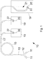
- FIG. 1 shows the schematic structure of a per se known particle therapy system 10.
- the particle therapy system 10 generates and accelerates charged particles, which are provided in the form of a particle beam 20 for further use and by means of a beam guide 17 in a definable target volume 34 (see FIG. 3 ) are steerable.
- the target volume 34 contains, for example, in the context of tumor therapy a tumor, but it can also be defined for scientific purposes, animal experiments, model and material samples and generally for research of particle beam and / or particle therapy, a target volume 34, which inanimate material and / or cell cultures contains.
- the particle therapy system 10 is also used for the irradiation of phantoms with the particle beam 20, by means of which a plurality of irradiation parameters can be verified before and / or after a successful irradiation or treatment of a patient.
- the particles are in the in FIG. 1 example shown in one of the two ion sources 11 and pre-accelerated.
- the ion sources 11 can provide a wide variety of particles from protons to uranium. Because of their properties advantageous for particle therapy, such as the characteristic (particle-dependent) interaction with matter and the penetration depth, preference is given to using protons, pions, helium ions or particularly preferably carbon ions. In general, hadrons are preferably used as particles.
- the particles in a pre-accelerator 13, in the case shown, the linear accelerator UNILAC 13 (Universal Linear Accelerator), threaded.
- the linear accelerator 13 accelerates the particles to a first energy level and bundles the particles into a particle beam 20.
- the particles are finally threaded into the accelerator unit 15, eg a synchrotron, or a cyclotron as shown, with another low-energy beam guide 12 there further accelerated to the adjustable extraction energy for each application.
- the beam guide 17 finally guides the particle beam 20 to the desired target, called "target", in a measuring space 19 or therapy room 21, where the particle beam 20 with a typical beam diameter of 3 to 30 millimeters can be applied or provided there.
- the order of approaching the target points 30 of the target volume 34 is recorded in an irradiation plan, which may further include other essential parameters, such as in particular the parameters of the target volume 34 and / or an expected movement of the target volume 34.
- One of the key benefits of the raster scan device 22 is in that it provides the possibility of directing the particle beam 20 permanently to the target volume 34 without activating it individually for starting the respective target point 30.
- the entire particle therapy system 10 is finally controlled by an accelerator control system, which in particular controls the accelerator unit 15 and the beam guide 17 and collects measurement data for monitoring beam parameters.
- the parameters for controlling the particle therapy system 10 may be adjusted based on the treatment plan so that the treatment plan also includes the adjustment data for controlling the particle therapy system 10.
- FIG. 2 shows a schematic representation of devices known per se, which in the preparation of the treatment plan, ie the treatment planning, for generating a data set, the target points 30 defined in a target volume 34 in a body 77, and in the control of an irradiation system 10, as for example based on FIG. 1 was shown, can be used.
- the position and extent of a tumor or another target volume 34 to be irradiated can be determined.
- Data from the scanner 71 is processed immediately or after conditioning by a device 81 to create a data set.
- the device 81 is, for example, a workstation computer, a workstation or another computer.
- the device 81 is further adapted, through its user interface, software, or other features, for medical personnel to define the target volume 34, the doses to be administered, the division thereof into multiple fractions, the direction of the irradiation, and other details of the particle therapy.
- the body 77 to be irradiated can be monitored with differently designed monitoring devices before, during or after the irradiation by the particle therapy system 10.
- a PET camera 72 Positron Emission Tomography
- a distance sensor 73 for detecting a body 77 to be irradiated, which is mounted on a bearing surface 78, are provided.
- the PET camera 72 and / or the distance sensor 73 and the bearing surface 78 can within one of the above with reference to FIG. 1 be shown 19 irradiation spaces arranged.
- the dose generated by a particle beam 20 and movements of the irradiated body 77 can be detected by means of the PET camera 72 and / or the distance sensor 73.
- the PET camera 72, the distance sensor 73, and the bearing surface 78 are disposed outside of an irradiation space.
- the body 77 may be monitored by means of a fluoroscopy device, an X-ray device, an ultrasound sensor, a breathing belt, and / or other external sensors.
- Data from the scanner 71, from the PET camera 72, and from the distance sensor 73 may be processed by means 82 for determining one or more motion parameters.
- movements of partial regions of the body 77 for example due to respiration or heartbeat
- the motion parameter (s) determined by the device 82 may be taken into account by the device 81 for creating a data set.
- data on the amplitudes of typical and / or periodic movements or on a relationship between the spatial position of the target volume and / or a variable that can be detected from outside are suitable for taking into account the creation of a data record.
- the device 82 can use specific parameters or data directly from a controller 86 for controlling an irradiation system 10, as described with reference to FIG FIG. 1 was presented, processed.
- Particularly suitable for this purpose are data which are acquired by the PET camera 72 or the distance sensor 73 during the irradiation.
- the control unit 86 is also the created by the device 81 record. Via control lines 87 or otherwise, the Control unit 86 coupled to the irradiation system 10.
- FIG. 1 The basis of the FIG. 1
- the illustrated basic structure of an irradiation facility 10 is typical for many particle therapy facilities and other irradiation facilities.
- the embodiments described below are both in connection with the basis of the FIG. 1 shown irradiation system and the basis of the FIG. 2 used devices as well as with other irradiation facilities and facilities used.
- FIG. 3 schematically shows an irradiation of a target volume.
- the accelerator unit 15 provides the particle beam 20, which is scanned with two magnetic scan pairs 40, 42 transversely to the beam direction of the particle beam, ie laterally over the target volume 34.
- the target points 30 of the target volume 34 define the dot grid of the target volume, the target points being arranged in a plurality of isoenergy layers, in the example shown the isoenergy layers 341 to 347.
- the isoenergy layers 341 to 347 are successively scanned with the particle beam 20.
- the isoenergy layer 345 is being scanned laterally.
- a movement of the target volume 34 is symbolized by the arrows 36. This can be detected by means of a movement detection device 46, which detects the movement of the body 77.
- the particle beam may have a round cross-section, so that the dose distribution concentrically decreases from the center of the beam outwardly decreases.
- a three-dimensional dose deposition which may also include target points 30 of neighboring isoenergy layers 344, 346, the calculation of the three-dimensional predososes and the selection of the irradiation order of the isoenergy layers, since this is already known from the above Figures on the full irradiation process can infer and in particular the irradiation plan for all Isoenergy Wegen 341 to 347 can adjust equally.
- the method based on the description and the figures on spatially distributed in the target volume 34 target points 30 can be transmitted.
- FIG. 4 shows the influence of the consideration of the movement on the dose distribution in the range of the target volume.
- the arrows 50 symbolize the movement, which in the case shown represents a periodic respiratory movement.
- the inner area shows the clinical target volume 52 (CTV Clinical Target Volume) enclosed by safety cavities 54 (IM Internal Margins).
- Target clinical volume 52 and safety margins 54 together form the target volume 55.
- This with the embodiments of the Figures 2 and 3 described target volume 34 may correspond to the target volume 55.
- a risk area 56 (OAR Organs At Risk), which is to be taken into account with particular care, that is to be burdened by the lowest possible radiation dose, is arranged adjacent to the target volume 55.
- the Step function 58 shows the usually desired desired dose distribution within the target volume 55.
- a homogeneous, lowest possible but lethal dose should be deposited in the entire target volume 55, which includes the clinical target volume 52 and the safety margins 54.
- the dose distribution typically deposited in tissue based on such uncorrected target dose distribution shows the distribution curve 60.
- Significant dose rate is typically also deposited in the risk area 56.
- the corrected distribution curve 62 finally shows the corrected target dose distribution 62 after the correction by the expected average movement of the target points 30 of the target volume 34, 55, as proposed by the invention.
- the consideration of the movement can therefore better adapt the dose distribution in the tissue to the target of the irradiation, namely the sufficiently high dose deposition in the clinical target volume 52.
- the safety seams 54 introduced earlier in the case of moving target volumes can therefore be narrowed using the methods according to the invention or, if appropriate, completely omitted. A better protection of the risk area 56 also takes place.
- the dose rate deposited in the tissue on the basis of the corrected target dose distribution 62 shows the distribution curve 64.
- the essential aim of the optimization is to adapt the target dose distribution to a moving target volume 55 and thus to limit the area in which a dose rate is deposited as far as possible to the target clinical volume 52 , This can be quite clearly the FIG. 4 remove.
- the target dose distribution 62 corrected in accordance with the invention produces a distribution curve 64 of the dose deposition which has significantly steeper flanks and is not so far away from the clinical target volume 52, ie thus relates to less surrounding material such as healthy tissue or risk areas 56.
- D plan represents the target dose and D i .
- ref ⁇ j N j denote the dose deposited at a target point i , 30 in the reference phase of the movement as a function of the particle numbers N j deposited at all target points j , 30.
- this function corresponds to the optimization of a static tumor, which is used for classical rescanning and requires consideration of safety margins around the tumor. This leads to increased irradiation of healthy tissue.
- the dose deposited at a target point i , 30 is calculated from the weighted average of the dose contributions from all expected movement states m .
- the movement of the target volume is explicitly taken into account by means of the movement model.
- this function it is possible to predict the anticipated dose dependency of each halftone dot, which is calculable for each phase of the movement and weighted by the probability function. This Thus, the optimization can be based on an actually expected 4D dose deposition, instead of the previous stationary 3D dose deposition. It is therefore a true 4D optimization, which can especially increase the conformity of the dose.
- this probability function may depend not only on the motion state m but also on the position of the target point j , 30. This would be the case, for example, if changes in the movement trajectory were known before the irradiation or if they were artificially induced.
- the state of motion may be set at the start of the startup of each isoenergy layer or the particle intensity may be varied during the irradiation.
- the application of the planned target dose thus takes place via the optimization, which, unlike in conventional rescanning, explicitly takes into account information from all states of motion, instead of being guaranteed solely via the determination of the safety margins 54.
- the area in which the dose is deposited can thus be reduced. In particular, this will result in better protection of vulnerable organs 56 located near the target clinical volume 52.
- the decision as to whether the safety spaces 54 are reduced or whether they may possibly even be dispensed with can either be taken manually or be adapted accordingly in an automatic optimization. Also is a use of conventional safety seams 54 with the method according to the invention conceivable, for example, to achieve an improved dose deposition in the case of respiratory patterns which deviate greatly from an even distribution of the states of motion, or to be better able to estimate the dose deposited in the risk organs 56, including the influence of movement.
- an average movement of the target points of the target volume can be calculated.
- the average calculated movement of the target points of the target volume can be taken into account in the treatment planning in order to increase the conformity of the dose deposition.
- the method can also be combined with the gating method so that the irradiation takes place only in a selected subset of all movement states. This could be e.g. Compared to pure gating with target volume 55 a larger gating window tolerated and thus the total exposure time can be reduced.
- the choice of gating window can be manual or part of the optimization.
- this method can be used by additionally measuring the course of the movement during the irradiation. If too large a deviation in the distribution of the movement phases from the assumed distribution is detected, various countermeasures can be taken, for example: pausing (gating) of the radiation during the dominant states of motion, rescheduling for the current or future fraction or fields, modulating the irradiated particle intensity (Increase during subdominant or reduction during dominant states of movement) and controlled breathing of the patient, eg via respiratory coaching or artificial respiration.
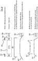
- FIG. 5 shows left hand eight steps of the irradiation planning procedure preceding the irradiation.
- patient data and the motion model to be applied are loaded.
- the patient data contain information about the dose rate to be applied, the extent of the target volume 34, 55, information about risk areas 56 and information about density courses in the body 77, so that the particle energies and the individual dose distributions can be calculated.
- the target volume 34, 55 is defined at step 102, and at step 103 a point grid, ie the target points 30 of the target volume, is defined.
- step 104 according to the example of FIG. 5 set the number of rescan passes.
- the target dose 58 is divided per target point 30 on the Rescan passes.
- step 105 the particle number per target point 30 is calculated, which is to be deposited with the particle beam 20 of the accelerator system 10.
- the number of particles per target point 30 can be calculated on the basis of the target dose 58 to be deposited.
- the selected motion model is applied to the target dose distribution 58 in the target volume 34, 55, and the average motion of the target points 30 is determined from the target Calculated motion model.
- a correction of the particle number takes place with step 107, whereby a corrected nominal dose 62 is calculated on the basis of the movement model.
- control parameters for the irradiation facility corrected on the basis of the movement model are generated with step 108 and can thus be retrieved in the irradiation plan for a later irradiation.
- the method for irradiating a target volume 34, 55 may be the following, also in FIG. 5 include outlined steps.
- the treatment plan is loaded into a control unit 86 for controlling the irradiation system 10, which already contains the patient data, the target volume and the dot matrix data as well as the corrected target dose distribution 62 prepared.
- a movement detection device 82 which can detect the movements of the target volume 34, 55 quantitatively, the movement of the target volume 34, 55 is preferably detected in step 112 during the entire irradiation process.
- control of the correct irradiation can also be carried out with the movement detection device 82.
- step 113 on the basis of the actual movement data of the target volume 34, 55 generated with the movement detection device 82, further control parameters are generated by means of which the control of the irradiation facility 10 can be continuously corrected if the actual movement data are based on the of the motion model precalculated motion data.
- a possibly to be made correction of the control of the irradiation system is performed with step 114, with which the irradiation system is finally controlled taking into account the control parameters and the other control parameters.
Landscapes
- Health & Medical Sciences (AREA)
- Engineering & Computer Science (AREA)
- Biomedical Technology (AREA)
- Pathology (AREA)
- Nuclear Medicine, Radiotherapy & Molecular Imaging (AREA)
- Radiology & Medical Imaging (AREA)
- Life Sciences & Earth Sciences (AREA)
- Animal Behavior & Ethology (AREA)
- General Health & Medical Sciences (AREA)
- Public Health (AREA)
- Veterinary Medicine (AREA)
- Radiation-Therapy Devices (AREA)
Applications Claiming Priority (2)
| Application Number | Priority Date | Filing Date | Title |
|---|---|---|---|
| DE102012112348.9A DE102012112348B4 (de) | 2012-12-14 | 2012-12-14 | Bestrahlungsplanung einer Partikelbestrahlung unter Berücksichtigung einer Bewegung eines Zielvolumens |
| PCT/EP2013/071858 WO2014090456A1 (de) | 2012-12-14 | 2013-10-18 | Bestrahlungsplanung einer partikelbestrahlung unter berücksichtigung einer bewegung eines zielvolumens |
Publications (2)
| Publication Number | Publication Date |
|---|---|
| EP2931369A1 EP2931369A1 (de) | 2015-10-21 |
| EP2931369B1 true EP2931369B1 (de) | 2017-05-03 |
Family
ID=49486463
Family Applications (1)
| Application Number | Title | Priority Date | Filing Date |
|---|---|---|---|
| EP13783019.6A Active EP2931369B1 (de) | 2012-12-14 | 2013-10-18 | Bestrahlungsplanung einer partikelbestrahlung unter berücksichtigung einer bewegung eines zielvolumens |
Country Status (7)
| Country | Link |
|---|---|
| US (1) | US10252082B2 (ko) |
| EP (1) | EP2931369B1 (ko) |
| JP (1) | JP6105081B2 (ko) |
| KR (1) | KR101662762B1 (ko) |
| CN (1) | CN104981272B (ko) |
| DE (1) | DE102012112348B4 (ko) |
| WO (1) | WO2014090456A1 (ko) |
Cited By (1)
| Publication number | Priority date | Publication date | Assignee | Title |
|---|---|---|---|---|
| US10252082B2 (en) | 2012-12-14 | 2019-04-09 | Gsi Helmholtzzentrum Für Schwerionenforschung Gmbh | Planning the irradiation of a particle beam while taking into consideration a movement of a target volume |
Families Citing this family (4)
| Publication number | Priority date | Publication date | Assignee | Title |
|---|---|---|---|---|
| US9789342B2 (en) * | 2015-05-18 | 2017-10-17 | Varian Medical Systems, Inc. | System and method for in-layer synchronization for fast spot rescanning |
| JP6527241B2 (ja) * | 2015-11-13 | 2019-06-05 | 株式会社日立製作所 | 粒子線治療システム |
| EP3324318A1 (en) * | 2016-11-17 | 2018-05-23 | RaySearch Laboratories AB | System and method for ion based radiotherapy treatment plan evaluation |
| US10583313B2 (en) * | 2017-01-11 | 2020-03-10 | Varian Medical Systems Particle Therapy Gmbh | Mitigation of interplay effect in particle radiation therapy |
Family Cites Families (13)
| Publication number | Priority date | Publication date | Assignee | Title |
|---|---|---|---|---|
| EP1584353A1 (en) * | 2004-04-05 | 2005-10-12 | Paul Scherrer Institut | A system for delivery of proton therapy |
| US10279196B2 (en) * | 2006-09-28 | 2019-05-07 | Accuray Incorporated | Radiation treatment planning using four-dimensional imaging data |
| JP5126770B2 (ja) * | 2006-12-20 | 2013-01-23 | 独立行政法人放射線医学総合研究所 | 粒子線照射システム、並びに、これに用いるコンピュータプログラム及びコンピュータ読み取り可能な記憶媒体 |
| DE102007045879B4 (de) * | 2007-09-25 | 2014-07-10 | Gsi Helmholtzzentrum Für Schwerionenforschung Gmbh | Bestrahlung eines bewegten Zielvolumens |
| DE102008027485B4 (de) * | 2008-06-09 | 2010-02-11 | Gsi Helmholtzzentrum Für Schwerionenforschung Gmbh | Deposition einer Solldosisverteilung in einem zyklisch bewegten Zielgebiet |
| DE102008036478A1 (de) * | 2008-08-05 | 2010-02-11 | Forschungszentrum Dresden - Rossendorf E.V. | Vorrichtung und Verfahren zur Auswertung einer Aktivitätsverteilung sowie Bestrahlungsanlage |
| US8212223B2 (en) * | 2009-06-09 | 2012-07-03 | Mitsubishi Electric Corporation | Particle beam irradiation apparatus |
| US8859264B2 (en) * | 2009-07-29 | 2014-10-14 | Gsi Helmholtzzentrum Fuer Schwerionenforschung Gmbh | Phantom for the experimental in-vitro validation of radiation procedures under the influence of motion, taking into account the biological effective dose |
| JP2012210232A (ja) * | 2009-08-19 | 2012-11-01 | Mitsubishi Electric Corp | 放射線治療システム |
| DE102009055902B4 (de) * | 2009-11-26 | 2013-02-21 | Gsi Helmholtzzentrum Für Schwerionenforschung Gmbh | Verfahren und Vorrichtung zur Steuerung der Dosisapplikation bei der Bestrahlung |
| US8280002B2 (en) * | 2010-07-01 | 2012-10-02 | Siemens Medical Solutions Usa, Inc. | Radiation treatment of moving targets |
| WO2012123894A1 (en) * | 2011-03-15 | 2012-09-20 | Koninklijke Philips Electronics N.V. | Studying dosimetric impact of motion to generate adaptive patient-specific margins in ebrt planning |
| DE102012112348B4 (de) | 2012-12-14 | 2014-11-06 | Gsi Helmholtzzentrum Für Schwerionenforschung Gmbh | Bestrahlungsplanung einer Partikelbestrahlung unter Berücksichtigung einer Bewegung eines Zielvolumens |
-
2012
- 2012-12-14 DE DE102012112348.9A patent/DE102012112348B4/de not_active Expired - Fee Related
-
2013
- 2013-10-18 JP JP2015546905A patent/JP6105081B2/ja not_active Expired - Fee Related
- 2013-10-18 US US14/651,884 patent/US10252082B2/en active Active
- 2013-10-18 EP EP13783019.6A patent/EP2931369B1/de active Active
- 2013-10-18 KR KR1020157018807A patent/KR101662762B1/ko active IP Right Grant
- 2013-10-18 WO PCT/EP2013/071858 patent/WO2014090456A1/de active Application Filing
- 2013-10-18 CN CN201380072785.7A patent/CN104981272B/zh active Active
Cited By (1)
| Publication number | Priority date | Publication date | Assignee | Title |
|---|---|---|---|---|
| US10252082B2 (en) | 2012-12-14 | 2019-04-09 | Gsi Helmholtzzentrum Für Schwerionenforschung Gmbh | Planning the irradiation of a particle beam while taking into consideration a movement of a target volume |
Also Published As
| Publication number | Publication date |
|---|---|
| WO2014090456A1 (de) | 2014-06-19 |
| CN104981272A (zh) | 2015-10-14 |
| JP6105081B2 (ja) | 2017-03-29 |
| US20150306424A1 (en) | 2015-10-29 |
| CN104981272B (zh) | 2019-11-05 |
| DE102012112348B4 (de) | 2014-11-06 |
| EP2931369A1 (de) | 2015-10-21 |
| DE102012112348A1 (de) | 2014-06-18 |
| US10252082B2 (en) | 2019-04-09 |
| KR20150120946A (ko) | 2015-10-28 |
| JP2015536770A (ja) | 2015-12-24 |
| KR101662762B1 (ko) | 2016-10-05 |
Similar Documents
| Publication | Publication Date | Title |
|---|---|---|
| EP2307096B1 (de) | Vorrichtung und verfahren zur auswertung einer aktivitätsverteilung sowie bestrahlungsanlage | |
| DE102009055902B4 (de) | Verfahren und Vorrichtung zur Steuerung der Dosisapplikation bei der Bestrahlung | |
| EP2352555B1 (de) | Vorrichtung und verfahren zur bestimmung von steuerparametern für eine bestrahlungsanlage | |
| DE102007045879B4 (de) | Bestrahlung eines bewegten Zielvolumens | |
| EP2285448B1 (de) | Deposition einer solldosisverteilung in einem zyklisch bewegten zielgebiet | |
| EP3342463B1 (de) | Verfahren und bestrahlungsanlage zur bestrahlung eines zielvolumens | |
| EP2482926B1 (de) | Verfahren und vorrichtung zur überprüfung einer bestrahlungsplanung sowie bestrahlungsanlage | |
| EP2931369B1 (de) | Bestrahlungsplanung einer partikelbestrahlung unter berücksichtigung einer bewegung eines zielvolumens | |
| EP2506929B1 (de) | Bestrahlungsvorrichtung | |
| EP2627410B1 (de) | Verfahren zur erstellung einer bestrahlungsplanung | |
| EP2916912B1 (de) | Verfahren zur bestrahlungsplanung | |
| WO2011006732A1 (de) | Vorrichtung und verfahren zur steuerung einer bestrahlungsanlage | |
| EP2366428B1 (de) | Verfahren zum Registrieren eines ersten Abbildungsdatensatzes zu einem zweiten Abbildungsdatensatz | |
| DE102011080368B4 (de) | Bestrahlungsplanung und Bestrahlung bei einem sich quasi-zyklisch bewegenden Zielvolumen | |
| EP2453982B1 (de) | Verfahren zur bestrahlung eines sich bewegenden zielvolumens sowie bestrahlungsanlage | |
| EP2453986B1 (de) | Verfahren zur bestrahlung eines sich bewegenden zielvolumens sowie bestrahlungsanlage |
Legal Events
| Date | Code | Title | Description |
|---|---|---|---|
| PUAI | Public reference made under article 153(3) epc to a published international application that has entered the european phase |
Free format text: ORIGINAL CODE: 0009012 |
|
| 17P | Request for examination filed |
Effective date: 20150526 |
|
| AK | Designated contracting states |
Kind code of ref document: A1 Designated state(s): AL AT BE BG CH CY CZ DE DK EE ES FI FR GB GR HR HU IE IS IT LI LT LU LV MC MK MT NL NO PL PT RO RS SE SI SK SM TR |
|
| AX | Request for extension of the european patent |
Extension state: BA ME |
|
| DAX | Request for extension of the european patent (deleted) | ||
| GRAJ | Information related to disapproval of communication of intention to grant by the applicant or resumption of examination proceedings by the epo deleted |
Free format text: ORIGINAL CODE: EPIDOSDIGR1 |
|
| GRAP | Despatch of communication of intention to grant a patent |
Free format text: ORIGINAL CODE: EPIDOSNIGR1 |
|
| GRAP | Despatch of communication of intention to grant a patent |
Free format text: ORIGINAL CODE: EPIDOSNIGR1 |
|
| INTG | Intention to grant announced |
Effective date: 20160518 |
|
| GRAJ | Information related to disapproval of communication of intention to grant by the applicant or resumption of examination proceedings by the epo deleted |
Free format text: ORIGINAL CODE: EPIDOSDIGR1 |
|
| GRAP | Despatch of communication of intention to grant a patent |
Free format text: ORIGINAL CODE: EPIDOSNIGR1 |
|
| GRAJ | Information related to disapproval of communication of intention to grant by the applicant or resumption of examination proceedings by the epo deleted |
Free format text: ORIGINAL CODE: EPIDOSDIGR1 |
|
| INTC | Intention to grant announced (deleted) | ||
| INTG | Intention to grant announced |
Effective date: 20160930 |
|
| GRAP | Despatch of communication of intention to grant a patent |
Free format text: ORIGINAL CODE: EPIDOSNIGR1 |
|
| GRAJ | Information related to disapproval of communication of intention to grant by the applicant or resumption of examination proceedings by the epo deleted |
Free format text: ORIGINAL CODE: EPIDOSDIGR1 |
|
| INTG | Intention to grant announced |
Effective date: 20161014 |
|
| INTG | Intention to grant announced |
Effective date: 20161021 |
|
| INTG | Intention to grant announced |
Effective date: 20161026 |
|
| GRAP | Despatch of communication of intention to grant a patent |
Free format text: ORIGINAL CODE: EPIDOSNIGR1 |
|
| INTG | Intention to grant announced |
Effective date: 20161102 |
|
| INTC | Intention to grant announced (deleted) | ||
| INTG | Intention to grant announced |
Effective date: 20161130 |
|
| GRAS | Grant fee paid |
Free format text: ORIGINAL CODE: EPIDOSNIGR3 |
|
| GRAA | (expected) grant |
Free format text: ORIGINAL CODE: 0009210 |
|
| AK | Designated contracting states |
Kind code of ref document: B1 Designated state(s): AL AT BE BG CH CY CZ DE DK EE ES FI FR GB GR HR HU IE IS IT LI LT LU LV MC MK MT NL NO PL PT RO RS SE SI SK SM TR |
|
| REG | Reference to a national code |
Ref country code: GB Ref legal event code: FG4D Free format text: NOT ENGLISH |
|
| REG | Reference to a national code |
Ref country code: AT Ref legal event code: REF Ref document number: 889308 Country of ref document: AT Kind code of ref document: T Effective date: 20170515 Ref country code: CH Ref legal event code: EP |
|
| REG | Reference to a national code |
Ref country code: IE Ref legal event code: FG4D Free format text: LANGUAGE OF EP DOCUMENT: GERMAN |
|
| REG | Reference to a national code |
Ref country code: DE Ref legal event code: R096 Ref document number: 502013007165 Country of ref document: DE |
|
| REG | Reference to a national code |
Ref country code: NL Ref legal event code: MP Effective date: 20170503 |
|
| REG | Reference to a national code |
Ref country code: LT Ref legal event code: MG4D |
|
| REG | Reference to a national code |
Ref country code: FR Ref legal event code: PLFP Year of fee payment: 5 |
|
| PG25 | Lapsed in a contracting state [announced via postgrant information from national office to epo] |
Ref country code: HR Free format text: LAPSE BECAUSE OF FAILURE TO SUBMIT A TRANSLATION OF THE DESCRIPTION OR TO PAY THE FEE WITHIN THE PRESCRIBED TIME-LIMIT Effective date: 20170503 Ref country code: FI Free format text: LAPSE BECAUSE OF FAILURE TO SUBMIT A TRANSLATION OF THE DESCRIPTION OR TO PAY THE FEE WITHIN THE PRESCRIBED TIME-LIMIT Effective date: 20170503 Ref country code: ES Free format text: LAPSE BECAUSE OF FAILURE TO SUBMIT A TRANSLATION OF THE DESCRIPTION OR TO PAY THE FEE WITHIN THE PRESCRIBED TIME-LIMIT Effective date: 20170503 Ref country code: LT Free format text: LAPSE BECAUSE OF FAILURE TO SUBMIT A TRANSLATION OF THE DESCRIPTION OR TO PAY THE FEE WITHIN THE PRESCRIBED TIME-LIMIT Effective date: 20170503 Ref country code: GR Free format text: LAPSE BECAUSE OF FAILURE TO SUBMIT A TRANSLATION OF THE DESCRIPTION OR TO PAY THE FEE WITHIN THE PRESCRIBED TIME-LIMIT Effective date: 20170804 Ref country code: NO Free format text: LAPSE BECAUSE OF FAILURE TO SUBMIT A TRANSLATION OF THE DESCRIPTION OR TO PAY THE FEE WITHIN THE PRESCRIBED TIME-LIMIT Effective date: 20170803 |
|
| PG25 | Lapsed in a contracting state [announced via postgrant information from national office to epo] |
Ref country code: NL Free format text: LAPSE BECAUSE OF FAILURE TO SUBMIT A TRANSLATION OF THE DESCRIPTION OR TO PAY THE FEE WITHIN THE PRESCRIBED TIME-LIMIT Effective date: 20170503 Ref country code: RS Free format text: LAPSE BECAUSE OF FAILURE TO SUBMIT A TRANSLATION OF THE DESCRIPTION OR TO PAY THE FEE WITHIN THE PRESCRIBED TIME-LIMIT Effective date: 20170503 Ref country code: IS Free format text: LAPSE BECAUSE OF FAILURE TO SUBMIT A TRANSLATION OF THE DESCRIPTION OR TO PAY THE FEE WITHIN THE PRESCRIBED TIME-LIMIT Effective date: 20170903 Ref country code: PL Free format text: LAPSE BECAUSE OF FAILURE TO SUBMIT A TRANSLATION OF THE DESCRIPTION OR TO PAY THE FEE WITHIN THE PRESCRIBED TIME-LIMIT Effective date: 20170503 Ref country code: SE Free format text: LAPSE BECAUSE OF FAILURE TO SUBMIT A TRANSLATION OF THE DESCRIPTION OR TO PAY THE FEE WITHIN THE PRESCRIBED TIME-LIMIT Effective date: 20170503 Ref country code: BG Free format text: LAPSE BECAUSE OF FAILURE TO SUBMIT A TRANSLATION OF THE DESCRIPTION OR TO PAY THE FEE WITHIN THE PRESCRIBED TIME-LIMIT Effective date: 20170803 Ref country code: LV Free format text: LAPSE BECAUSE OF FAILURE TO SUBMIT A TRANSLATION OF THE DESCRIPTION OR TO PAY THE FEE WITHIN THE PRESCRIBED TIME-LIMIT Effective date: 20170503 |
|
| PG25 | Lapsed in a contracting state [announced via postgrant information from national office to epo] |
Ref country code: SK Free format text: LAPSE BECAUSE OF FAILURE TO SUBMIT A TRANSLATION OF THE DESCRIPTION OR TO PAY THE FEE WITHIN THE PRESCRIBED TIME-LIMIT Effective date: 20170503 Ref country code: EE Free format text: LAPSE BECAUSE OF FAILURE TO SUBMIT A TRANSLATION OF THE DESCRIPTION OR TO PAY THE FEE WITHIN THE PRESCRIBED TIME-LIMIT Effective date: 20170503 Ref country code: RO Free format text: LAPSE BECAUSE OF FAILURE TO SUBMIT A TRANSLATION OF THE DESCRIPTION OR TO PAY THE FEE WITHIN THE PRESCRIBED TIME-LIMIT Effective date: 20170503 Ref country code: CZ Free format text: LAPSE BECAUSE OF FAILURE TO SUBMIT A TRANSLATION OF THE DESCRIPTION OR TO PAY THE FEE WITHIN THE PRESCRIBED TIME-LIMIT Effective date: 20170503 Ref country code: DK Free format text: LAPSE BECAUSE OF FAILURE TO SUBMIT A TRANSLATION OF THE DESCRIPTION OR TO PAY THE FEE WITHIN THE PRESCRIBED TIME-LIMIT Effective date: 20170503 |
|
| PGFP | Annual fee paid to national office [announced via postgrant information from national office to epo] |
Ref country code: FR Payment date: 20171023 Year of fee payment: 5 |
|
| REG | Reference to a national code |
Ref country code: DE Ref legal event code: R097 Ref document number: 502013007165 Country of ref document: DE |
|
| PG25 | Lapsed in a contracting state [announced via postgrant information from national office to epo] |
Ref country code: SM Free format text: LAPSE BECAUSE OF FAILURE TO SUBMIT A TRANSLATION OF THE DESCRIPTION OR TO PAY THE FEE WITHIN THE PRESCRIBED TIME-LIMIT Effective date: 20170503 |
|
| PGFP | Annual fee paid to national office [announced via postgrant information from national office to epo] |
Ref country code: CH Payment date: 20171023 Year of fee payment: 5 Ref country code: IT Payment date: 20171020 Year of fee payment: 5 |
|
| PLBE | No opposition filed within time limit |
Free format text: ORIGINAL CODE: 0009261 |
|
| STAA | Information on the status of an ep patent application or granted ep patent |
Free format text: STATUS: NO OPPOSITION FILED WITHIN TIME LIMIT |
|
| 26N | No opposition filed |
Effective date: 20180206 |
|
| PG25 | Lapsed in a contracting state [announced via postgrant information from national office to epo] |
Ref country code: SI Free format text: LAPSE BECAUSE OF FAILURE TO SUBMIT A TRANSLATION OF THE DESCRIPTION OR TO PAY THE FEE WITHIN THE PRESCRIBED TIME-LIMIT Effective date: 20170503 Ref country code: MC Free format text: LAPSE BECAUSE OF FAILURE TO SUBMIT A TRANSLATION OF THE DESCRIPTION OR TO PAY THE FEE WITHIN THE PRESCRIBED TIME-LIMIT Effective date: 20170503 |
|
| GBPC | Gb: european patent ceased through non-payment of renewal fee |
Effective date: 20171018 |
|
| REG | Reference to a national code |
Ref country code: IE Ref legal event code: MM4A |
|
| PG25 | Lapsed in a contracting state [announced via postgrant information from national office to epo] |
Ref country code: LU Free format text: LAPSE BECAUSE OF NON-PAYMENT OF DUE FEES Effective date: 20171018 Ref country code: GB Free format text: LAPSE BECAUSE OF NON-PAYMENT OF DUE FEES Effective date: 20171018 |
|
| REG | Reference to a national code |
Ref country code: BE Ref legal event code: MM Effective date: 20171031 |
|
| PG25 | Lapsed in a contracting state [announced via postgrant information from national office to epo] |
Ref country code: BE Free format text: LAPSE BECAUSE OF NON-PAYMENT OF DUE FEES Effective date: 20171031 |
|
| PG25 | Lapsed in a contracting state [announced via postgrant information from national office to epo] |
Ref country code: MT Free format text: LAPSE BECAUSE OF FAILURE TO SUBMIT A TRANSLATION OF THE DESCRIPTION OR TO PAY THE FEE WITHIN THE PRESCRIBED TIME-LIMIT Effective date: 20170503 |
|
| PG25 | Lapsed in a contracting state [announced via postgrant information from national office to epo] |
Ref country code: IE Free format text: LAPSE BECAUSE OF NON-PAYMENT OF DUE FEES Effective date: 20171018 |
|
| REG | Reference to a national code |
Ref country code: CH Ref legal event code: PL |
|
| PG25 | Lapsed in a contracting state [announced via postgrant information from national office to epo] |
Ref country code: HU Free format text: LAPSE BECAUSE OF FAILURE TO SUBMIT A TRANSLATION OF THE DESCRIPTION OR TO PAY THE FEE WITHIN THE PRESCRIBED TIME-LIMIT; INVALID AB INITIO Effective date: 20131018 |
|
| PG25 | Lapsed in a contracting state [announced via postgrant information from national office to epo] |
Ref country code: CH Free format text: LAPSE BECAUSE OF NON-PAYMENT OF DUE FEES Effective date: 20181031 Ref country code: LI Free format text: LAPSE BECAUSE OF NON-PAYMENT OF DUE FEES Effective date: 20181031 Ref country code: FR Free format text: LAPSE BECAUSE OF NON-PAYMENT OF DUE FEES Effective date: 20181031 |
|
| PG25 | Lapsed in a contracting state [announced via postgrant information from national office to epo] |
Ref country code: IT Free format text: LAPSE BECAUSE OF NON-PAYMENT OF DUE FEES Effective date: 20181018 Ref country code: CY Free format text: LAPSE BECAUSE OF FAILURE TO SUBMIT A TRANSLATION OF THE DESCRIPTION OR TO PAY THE FEE WITHIN THE PRESCRIBED TIME-LIMIT Effective date: 20170503 |
|
| PG25 | Lapsed in a contracting state [announced via postgrant information from national office to epo] |
Ref country code: MK Free format text: LAPSE BECAUSE OF FAILURE TO SUBMIT A TRANSLATION OF THE DESCRIPTION OR TO PAY THE FEE WITHIN THE PRESCRIBED TIME-LIMIT Effective date: 20170503 |
|
| REG | Reference to a national code |
Ref country code: AT Ref legal event code: MM01 Ref document number: 889308 Country of ref document: AT Kind code of ref document: T Effective date: 20181018 |
|
| PG25 | Lapsed in a contracting state [announced via postgrant information from national office to epo] |
Ref country code: AT Free format text: LAPSE BECAUSE OF NON-PAYMENT OF DUE FEES Effective date: 20181018 |
|
| PG25 | Lapsed in a contracting state [announced via postgrant information from national office to epo] |
Ref country code: TR Free format text: LAPSE BECAUSE OF FAILURE TO SUBMIT A TRANSLATION OF THE DESCRIPTION OR TO PAY THE FEE WITHIN THE PRESCRIBED TIME-LIMIT Effective date: 20170503 |
|
| PG25 | Lapsed in a contracting state [announced via postgrant information from national office to epo] |
Ref country code: PT Free format text: LAPSE BECAUSE OF FAILURE TO SUBMIT A TRANSLATION OF THE DESCRIPTION OR TO PAY THE FEE WITHIN THE PRESCRIBED TIME-LIMIT Effective date: 20170503 |
|
| PG25 | Lapsed in a contracting state [announced via postgrant information from national office to epo] |
Ref country code: AL Free format text: LAPSE BECAUSE OF FAILURE TO SUBMIT A TRANSLATION OF THE DESCRIPTION OR TO PAY THE FEE WITHIN THE PRESCRIBED TIME-LIMIT Effective date: 20170503 |
|
| PGFP | Annual fee paid to national office [announced via postgrant information from national office to epo] |
Ref country code: DE Payment date: 20221020 Year of fee payment: 10 |