EP2931084B1 - Hybrid mattress assemblies - Google Patents
Hybrid mattress assemblies Download PDFInfo
- Publication number
- EP2931084B1 EP2931084B1 EP13799158.4A EP13799158A EP2931084B1 EP 2931084 B1 EP2931084 B1 EP 2931084B1 EP 13799158 A EP13799158 A EP 13799158A EP 2931084 B1 EP2931084 B1 EP 2931084B1
- Authority
- EP
- European Patent Office
- Prior art keywords
- layer
- mattress
- foam
- core
- mattress core
- Prior art date
- Legal status (The legal status is an assumption and is not a legal conclusion. Google has not performed a legal analysis and makes no representation as to the accuracy of the status listed.)
- Active
Links
- 230000000712 assembly Effects 0.000 title description 17
- 238000000429 assembly Methods 0.000 title description 17
- 239000006260 foam Substances 0.000 claims description 81
- 210000004027 cell Anatomy 0.000 claims description 48
- 229920005830 Polyurethane Foam Polymers 0.000 claims description 22
- 239000011496 polyurethane foam Substances 0.000 claims description 22
- 239000012782 phase change material Substances 0.000 claims description 10
- 210000003850 cellular structure Anatomy 0.000 claims description 7
- 229920001821 foam rubber Polymers 0.000 claims description 4
- 230000000284 resting effect Effects 0.000 claims description 3
- 239000012530 fluid Substances 0.000 claims description 2
- 239000010410 layer Substances 0.000 description 138
- 239000004744 fabric Substances 0.000 description 14
- 229920002635 polyurethane Polymers 0.000 description 9
- 239000004814 polyurethane Substances 0.000 description 9
- 239000000853 adhesive Substances 0.000 description 8
- 239000012792 core layer Substances 0.000 description 7
- 238000000034 method Methods 0.000 description 7
- 230000001070 adhesive effect Effects 0.000 description 6
- 125000006850 spacer group Chemical group 0.000 description 6
- 229920000079 Memory foam Polymers 0.000 description 5
- 238000010276 construction Methods 0.000 description 5
- 239000000463 material Substances 0.000 description 5
- 239000008210 memory foam Substances 0.000 description 5
- 229910000831 Steel Inorganic materials 0.000 description 3
- 239000010959 steel Substances 0.000 description 3
- 229920001247 Reticulated foam Polymers 0.000 description 2
- 210000002421 cell wall Anatomy 0.000 description 2
- 230000006835 compression Effects 0.000 description 2
- 238000007906 compression Methods 0.000 description 2
- 238000004519 manufacturing process Methods 0.000 description 2
- 235000019645 odor Nutrition 0.000 description 2
- 229920003023 plastic Polymers 0.000 description 2
- 239000004033 plastic Substances 0.000 description 2
- -1 polyethylene Polymers 0.000 description 2
- 239000003190 viscoelastic substance Substances 0.000 description 2
- RNFJDJUURJAICM-UHFFFAOYSA-N 2,2,4,4,6,6-hexaphenoxy-1,3,5-triaza-2$l^{5},4$l^{5},6$l^{5}-triphosphacyclohexa-1,3,5-triene Chemical compound N=1P(OC=2C=CC=CC=2)(OC=2C=CC=CC=2)=NP(OC=2C=CC=CC=2)(OC=2C=CC=CC=2)=NP=1(OC=1C=CC=CC=1)OC1=CC=CC=C1 RNFJDJUURJAICM-UHFFFAOYSA-N 0.000 description 1
- WZRJTRPJURQBRM-UHFFFAOYSA-N 4-amino-n-(5-methyl-1,2-oxazol-3-yl)benzenesulfonamide;5-[(3,4,5-trimethoxyphenyl)methyl]pyrimidine-2,4-diamine Chemical compound O1C(C)=CC(NS(=O)(=O)C=2C=CC(N)=CC=2)=N1.COC1=C(OC)C(OC)=CC(CC=2C(=NC(N)=NC=2)N)=C1 WZRJTRPJURQBRM-UHFFFAOYSA-N 0.000 description 1
- RYGMFSIKBFXOCR-UHFFFAOYSA-N Copper Chemical compound [Cu] RYGMFSIKBFXOCR-UHFFFAOYSA-N 0.000 description 1
- 206010011985 Decubitus ulcer Diseases 0.000 description 1
- 241001669679 Eleotris Species 0.000 description 1
- 239000004593 Epoxy Substances 0.000 description 1
- 239000004831 Hot glue Substances 0.000 description 1
- RRHGJUQNOFWUDK-UHFFFAOYSA-N Isoprene Chemical compound CC(=C)C=C RRHGJUQNOFWUDK-UHFFFAOYSA-N 0.000 description 1
- 239000004698 Polyethylene Substances 0.000 description 1
- 239000004743 Polypropylene Substances 0.000 description 1
- 208000004210 Pressure Ulcer Diseases 0.000 description 1
- RTAQQCXQSZGOHL-UHFFFAOYSA-N Titanium Chemical compound [Ti] RTAQQCXQSZGOHL-UHFFFAOYSA-N 0.000 description 1
- 239000000654 additive Substances 0.000 description 1
- 230000002009 allergenic effect Effects 0.000 description 1
- 229910052782 aluminium Inorganic materials 0.000 description 1
- XAGFODPZIPBFFR-UHFFFAOYSA-N aluminium Chemical compound [Al] XAGFODPZIPBFFR-UHFFFAOYSA-N 0.000 description 1
- 230000004888 barrier function Effects 0.000 description 1
- 230000006399 behavior Effects 0.000 description 1
- 230000001413 cellular effect Effects 0.000 description 1
- 238000004891 communication Methods 0.000 description 1
- 239000010949 copper Substances 0.000 description 1
- 229910052802 copper Inorganic materials 0.000 description 1
- 229920001971 elastomer Polymers 0.000 description 1
- 230000001747 exhibiting effect Effects 0.000 description 1
- 239000000835 fiber Substances 0.000 description 1
- 239000003063 flame retardant Substances 0.000 description 1
- 239000006261 foam material Substances 0.000 description 1
- 230000004927 fusion Effects 0.000 description 1
- 239000004816 latex Substances 0.000 description 1
- 229920000126 latex Polymers 0.000 description 1
- 230000014759 maintenance of location Effects 0.000 description 1
- 229910052751 metal Inorganic materials 0.000 description 1
- 239000002184 metal Substances 0.000 description 1
- 239000000203 mixture Substances 0.000 description 1
- 238000000465 moulding Methods 0.000 description 1
- 238000004806 packaging method and process Methods 0.000 description 1
- 230000002093 peripheral effect Effects 0.000 description 1
- 229920000573 polyethylene Polymers 0.000 description 1
- 229920001155 polypropylene Polymers 0.000 description 1
- 230000002028 premature Effects 0.000 description 1
- 238000011084 recovery Methods 0.000 description 1
- 239000005060 rubber Substances 0.000 description 1
- 239000000565 sealant Substances 0.000 description 1
- 239000002356 single layer Substances 0.000 description 1
- 239000007787 solid Substances 0.000 description 1
- 239000000126 substance Substances 0.000 description 1
- 239000010936 titanium Substances 0.000 description 1
- 229910052719 titanium Inorganic materials 0.000 description 1
- 238000009423 ventilation Methods 0.000 description 1
Images
Classifications
-
- A—HUMAN NECESSITIES
- A47—FURNITURE; DOMESTIC ARTICLES OR APPLIANCES; COFFEE MILLS; SPICE MILLS; SUCTION CLEANERS IN GENERAL
- A47C—CHAIRS; SOFAS; BEDS
- A47C27/00—Spring, stuffed or fluid mattresses or cushions specially adapted for chairs, beds or sofas
- A47C27/04—Spring, stuffed or fluid mattresses or cushions specially adapted for chairs, beds or sofas with spring inlays
- A47C27/05—Spring, stuffed or fluid mattresses or cushions specially adapted for chairs, beds or sofas with spring inlays with padding material, e.g. foamed material, in top, bottom, or side layers
- A47C27/056—Spring, stuffed or fluid mattresses or cushions specially adapted for chairs, beds or sofas with spring inlays with padding material, e.g. foamed material, in top, bottom, or side layers with different layers of foamed material
-
- A—HUMAN NECESSITIES
- A47—FURNITURE; DOMESTIC ARTICLES OR APPLIANCES; COFFEE MILLS; SPICE MILLS; SUCTION CLEANERS IN GENERAL
- A47C—CHAIRS; SOFAS; BEDS
- A47C27/00—Spring, stuffed or fluid mattresses or cushions specially adapted for chairs, beds or sofas
- A47C27/04—Spring, stuffed or fluid mattresses or cushions specially adapted for chairs, beds or sofas with spring inlays
- A47C27/05—Spring, stuffed or fluid mattresses or cushions specially adapted for chairs, beds or sofas with spring inlays with padding material, e.g. foamed material, in top, bottom, or side layers
- A47C27/053—Spring, stuffed or fluid mattresses or cushions specially adapted for chairs, beds or sofas with spring inlays with padding material, e.g. foamed material, in top, bottom, or side layers with only one layer of foamed material
-
- A—HUMAN NECESSITIES
- A47—FURNITURE; DOMESTIC ARTICLES OR APPLIANCES; COFFEE MILLS; SPICE MILLS; SUCTION CLEANERS IN GENERAL
- A47C—CHAIRS; SOFAS; BEDS
- A47C27/00—Spring, stuffed or fluid mattresses or cushions specially adapted for chairs, beds or sofas
- A47C27/04—Spring, stuffed or fluid mattresses or cushions specially adapted for chairs, beds or sofas with spring inlays
- A47C27/06—Spring inlays
- A47C27/063—Spring inlays wrapped or otherwise protected
- A47C27/064—Pocketed springs
Definitions
- the present disclosure generally relates to mattress cores and mattress assemblies, and more particularly, to hybrid mattress cores and assemblies including an upper most foam layer and at least one coil spring layer disposed a viscoelastic foam support layer.
- Mattresses such as those formed of polyurethane foam, latex foam, and the like, with or without coiled springs, are generally known in the art.
- One of the ongoing problems associated with mattress assemblies is user comfort.
- these mattresses are often fabricated with multiple foam layers having varying properties such as density and hardness, among others, to suit the needs of the intended user.
- manufacturers have employed so called memory foams, also commonly referred to as viscoelastic foams, which are typically a combination of polyurethane and one or more additives that increase foam density and viscosity, thereby increasing its viscoelasticity.
- These foams are often open cell foam structures having both closed and open cells but in some instances may be reticulated foam structures.
- the memory foam When used in a mattress, the memory foam conforms to the shape of a user when the user exerts pressure onto the foam, thereby minimizing pressure points from the user's body. The memory foam then returns to its original shape when the user and associated pressure are removed. However, the return to the original shape is a relatively slow process because of the viscoelastic cellular structure of these types of foams.
- the high density of foams used in current mattress assemblies generally prevents proper ventilation.
- the foam material can exhibit an uncomfortable level of heat to the user after a period of time.
- these foams can retain a high level of moisture, further causing discomfort to the user and potentially leading to foul odors.
- a mattress assembly especially a mattress including one or more layers of viscoelastic memory foam, with an improved airflow to effectively dissipate user heat. Still further, it would be desirable to provide foam mattress assemblies with increased user comfort.
- US 2007/204407 relates to a foam integrated innerspring mattress and method of manufacture, wherein a flexible polyurethane foam is adhered onto the top and bottom of individually wrapped pocket innersprings, and additional polyurethane foam is molded onto the sides of the mattress.
- an elongated mattress core according to claim 1 is provided.
- a mattress assembly comprises a mattress core of the invention as defined above; and a side rail assembly circumscribing a perimeter of the mattress core, the side rail assembly comprising a layer of a polyurethane foam comprising an open cellular structure, wherein the open cellular structure comprises about 25 to 102 cells per cm (about 10 to about 40 cells per inch), a hardness of about 15.9 kgf to 45.4 kgf (about 35 pounds-force to about 100 pounds-force), and a density of about 19.2 kg/m 3 to 32.0 kg/m 3 (about 1.2 pounds per cubic foot to about 2.0 pounds per cubic foot), wherein the layer is configured to be disposed about a perimeter of an inner core of the mattress and is configured to permit the flow of fluid from and to the mattress core through the layer.
- the mattress assemblies include a combination of foam layers and at least one coil spring layer, wherein the at least one coil spring layer is disposed directly on an underlying viscoelastic foam layer. Additional foam layers of any type can be provided to overlay and/or underlay the combination of the coil spring layer and the underlying viscoelastic foam layer.
- the mattress assemblies may be a mattress of any size, including standard sizes such as a twin, queen, oversized queen, king, or California king sized mattress, as well as custom or non-standard sizes constructed to accommodate a particular user or a particular room.
- the mattress assemblies can be configured as one sided or two sided mattresses depending on the configuration and the desired application.
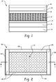
- FIG. 1 there is depicted a mattress core 10 for use in a mattress assembly including a plurality of layers.
- the mattress core 10 has at least one coil spring layer 12 disposed on a viscoelastic foam layer 14.
- One or more additional foam layers 16, 18, 20, 22, and 24 of any type may be included as may be desired to attain a desired mattress thickness. Although five additional layers are depicted, more or less foam layers can be employed.
- the thicknesses of the various foam layers including the viscoelastic foam layer 14 can vary and are generally from about 1.3cm to 30.5cm (about 1 ⁇ 2 inch in thickness to about 12 inches) in thickness.
- the Applicants have discovered that by providing at least one coil layer on an underlying viscoelastic layer, improved user comfort results.
- improved temperature management results since airflow into and out of the core is increased relative to an all-foam mattress.
- Viscoelastic polyurethane foam has an open-cell structure that reacts to body heat and weight by molding to the sleeper's body, helping relieve pressure points, preventing pressure sores, and the like. Most viscoelastic polyurethane foams have the same basic chemical composition; however the density and layer thickness of the foam makes different mattresses feel very different. A high-density mattress will have better compression ratings over the life of the bedding. A lower-density one will generally have slightly shorter life due to the compression that takes place after repeated use. Cell structures can vary from very open to almost closed cell. The tighter the cell structure, the less airflow through the foam. Breathable viscoelastic foam will have a more open cell structure, allowing higher airflow, better recovery, and lower odor retention at packaging.
- the coil springs are not intended to be limited to any specific type or shape.
- the coil springs can be single stranded or multi-stranded, pocketed or not pocketed, asymmetric or symmetric, and the like.
- the pocket coils may be manufactured in single pocket coils or strings of pocket coils, either of which may be suitably employed with the mattresses described herein.
- the attachment between coil springs may be any suitable attachment.
- pocket coils are commonly attached to one another using hot-melt adhesive applied to abutting surfaces during construction.
- the proposed coil spring construction for use in the mattress assembly can employ a stranded wire spring which is made of at least 2 wire strands that are twisted to form a multi-wire cord.
- the number of strands employed will vary according to the application and may vary based on the type of material used to form the strand.
- the wire may include two or more strands, and can include from three to fifty strands.
- the strands may be twisted, weaved, clipped or bonded together and any suitable method for forming the stranded wire spring may be employed without departing from the scope of the invention.
- the strands may be steel, aluminum, plastic, copper, titanium, rubber or any other suitable material and the type of material selected will depend upon the application at hand.
- the strands may have any suitable shape and may be long cylindrical wires, hexagonal wire, square wire or any other shape or geometry.
- the wire strand gauge may vary according to the application and in one embodiment comprises 710 gauge wire, although other gauges may be used.
- coiling may be achieved construction by passing a braided strand through a coiler, such as the type of coiler employed for forming steel mattress coils wherein a heavy-gauge steel wire is compressed into a barrel-shaped coil such that no turns touch for eliminating noise and vibration.
- the coils may then be passed to a pocketing machine or station to pocket the springs into individual sleeves of a non-woven, non-allergenic fabric such as Duon.
- Each sleeve may be ultrasonically sealed, a process where the fibers are melted together to form solid plastic seams that are secure and tear-resistant.
- the coils are then fusion bonded to produce a strong, stable construction.
- the number of coils in each unit may vary, and the types of coils and the number of strands and gauge of strands can vary from pocket to pocket.
- the individual strands are connected with each other at least at the ends of the coil. Since the strands can rub against each other over the length of the coil, which can cause fretting and premature wear, the strands may be coated and/or pre-galvanized. Moreover, the stranded coil may also be sealed with a sealant, such as an epoxy. Thus, in alternative and optional embodiments, the strands may be coated or otherwise treated and the wire may be sealed or coated. Exemplary stranded wire for use in mattresses is disclosed in US Pat. No. 7,047,581 , US Pat. No. 7,168,117 , and US Pat. No. 8,099,811 .
- the coil springs may optionally be encased, i.e., pocketed, in an envelope or an open coil and arranged in rows.
- the construction of the coil spring layer may be a plurality of rows of parallel coils with the coils aligned in columns so that the coils line up in both longitudinal and lateral directions or they may be nested in a honeycomb configuration wherein coils in one row are offset from coils in an adjacent row as is generally known in the art.
- Adjacent spring coils may be connected with adhesive.
- adjacent spring coils may be connected with a hog ring or other metal fasteners. In yet other embodiments, adjacent spring coils are not connected along the upper portion of the coils.
- the coils can be of any diameter; be symmetrical or asymmetrical, be designed with linear or non-linear behavior, or the like as may be desired for the different intended applications.
- the length of the coils range from 1 to 10 inches; and 2 to 6 inches in other embodiments.
- Suitable other foam layers include, without limitation, synthetic and natural latex, polyurethane, polyethylene, polypropylene, and the like.
- one or more of the foam layers may be pre-stressed such as is disclosed in US Pat. Pub. No. 2010/0072676 .
- the one or more additional layers may include a relatively firm bottom panel layer that distributes the upward force of each spring top to provide a more uniform feel to the sleeping surface.
- the combination of the coil spring layer disposed in direct contact on the viscoelastic foam layer will overlay the bottom panel layer.
- the mattress assemblies may be manufactured using techniques known in the art of mattress making, with variations to achieve the mattress described above.
- the various mattress layers in the mattress assemblies described above may be adjoined to one another using an adhesive or may be thermally bonded to one another or may be mechanically fastened to one using another hog rings, staples, and/or other techniques known in the art.
- a mattress core having an overall thickness of 27.9m (11 inches) includes, in sequence from bottom to top, a 5.1 cm (2 inch) layer of pre-stressed polyurethane (P85), a 2.5 cm (1 inch) pre-stressed latex layer (L-30), a 1.3cm (1 ⁇ 2 inch) viscoelastic foam layer having a density of 40.0 kg/m 3 (2.5 lb/ft 3 ), 8.9 cm(3.5 inch) stranded pocketed coil spring, 5.1 cm (2 inches) of pre-stressed polyurethane foam layer (P11); a 2.5 cm (1 inch) viscoelastic foam layer having a density of 72.1 kg/m 3 (4.5 lb/ft 3 ), and a 2.5 cm (1 inch) microgel infused phase change material foam layer having a convoluted surface with the tips facing downwards.
- the microgel infused phase change material layer overlies the foam layers, and in some embodiments, will overly a side rail assembly that circumscribes
- the core is disposed on a 5.1 cm (2 inch) layer of pre-stressed polyurethane (P85) and includes a 5.1 cm (2 inch) pre-stressed polyurethane foam layer (P85), a 1.3cm (1/2 inch) thick viscoelastic foam layer having a density of 72.1 kg/m 3 (4.5 lb/ft 3 ), a 8.9cm (3.5 inch) coil spring, a 2.5 cm (1 inch) thick viscoelastic foam layer having a density of 72.1 kg/m 3 (4.5 lb/ft 3 ), a 2.5 cm (1 inch) pre-stressed polyurethane foam layer (P85), and a 5.1 cm (2 inch) microgel infused phase change material layer having a convoluted surface with the tips facing downwards.
- the microgel infused phase change material layer overlies the foam layers, and in some embodiments, will overly a side rail assembly that circumscribes a perimeter of the
- the core is disposed on a 7.6cm (3 inch) layer of pre-stressed polyurethane (P85) and includes a 3.8cm (1.5 inch) pre-stressed latex foam layer (L-30), a 2.5cm (1 inch) thick viscoelastic foam layer having a density of 72.1 kg/m 3 (4.5 lb/ft 3 ), a 3.5 inch coil spring, a 5.1 cm (2 inch) of thick viscoelastic foam layer having a density of 72.1 kg/m 3 (4.5 lb/ft 3 ), and a 5.1 cm (2 inch) microgel infused phase change material layer having a convoluted surface with the tips facing downwards.
- the microgel infused phase change material layer overlies the foam layers and the 20.3 (8 inch) thick foam rails that are circumscribing the perimeter of the various layers seated on the polyurethane base layer.
- the core is disposed on a 10.2cm (4 inch) layer of pre-stressed polyurethane foam layer (P85) and includes a 5.1 cm (2 inch) viscoelastic foam layer having a density of 88.1 kg/m 3 (5.5 lb/ft 3 ), a 8.9cm (3.5 inch) coil spring layer, 1.3cm (1 ⁇ 2 inch) of a latex foam layer having a ILD of 14, 1.3cm (1 ⁇ 2 inch) of viscoelastic foam layer having a density of 88.1 kg/m 3 (5.5 lb/ft 3 ), a 3.8cm (1.5 inch) pre-stressed polyurethane foam layer (P85), and a 10.2cm (4 inch) microgel infused phase change material layer having a convoluted surface with the tips facing downwards.
- the microgel infused phase change material layer overlies the foam layers, and in some embodiments, will overly a side rail assembly that circumscribe
- the various multiply stacked layers may be adjoined to one another using an adhesive or may be thermally bonded to one another or may be mechanically fastened to one another.
- the combination of the foam layers and the at least one coil spring layer in the various mattress core embodiments can be encased with a high airflow side rail system to define the respective mattress assembly.
- encasement it is meant that the side rail assemblies can be disposed about a perimeter of the mattress inner core and provide support to a peripheral edge of a mattress. At least a portion of the side rail assembly, in some embodiments the entire assembly, in other embodiments one or more layers, is comprised of the high airflow foam, which is described in detail below.
- FIGS. 2-3 a top down view representative of an exemplary mattress assembly 50 including a mattress core 10 and a high airflow side rail assembly 100 is illustrated.
- the various embodiments of the mattress assemblies have in common the following components: multiple stacked layers including at least one coil spring layer disposed on a viscoelastic layer that defines the mattress core 10 wherein the uppermost foam layer 24 of the mattress core is shown, a side rail assembly 100 about at least a portion of the perimeter of the stacked mattress layers, and an optional fabric covering 104 about the side rail assembly 100 as shown, i.e., mattress border.
- the uppermost layer 24 is generally referred to herein as the cover layer and has a planar top surface adapted to substantially face the user resting on the mattress assembly and having a length and width dimensions sufficient to support a reclining body of the user.
- Said upper most layer 24 is a microgel infused phase change material layer having a convoluted surface with the tips facing downwards.
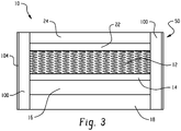
- FIG. 3 shows a cross sectional view of a mattress assembly taken along lines 1-1 of FIG. 2 .
- the mattress assembly 50 includes a base core foam layer 18 configured with generally planar top and bottom surfaces.
- the base core foam layer 18 is chosen to have a thickness greater than or equal to the overall thickness of the mattress assembly.
- the thickness of the base core foam layer 18 is 2.5cm to 15.2cm (1 inch to 6 inches), and a thickness of about 2.5cm to 10.2cm (about 1 inch to 4 inches) thickness in other embodiments.
- the base core foam layer 18 can be formed of standard polyurethane foam although other foams can be used, including without limitation, viscoelastic foams.
- the base core foam layer is an open cell polyurethane foam and is pre-stressed.
- Suitable pre-stressed polyurethane foams are generally formed in the manner disclosed in U.S. Pat. No. 7,690,096 to Gladney et al.
- a force can be applied to at least a section of a standard polyurethane foam layer in an amount sufficient to temporarily compress its height so as to permanently alter a mechanical property of the foam layer to provide a pre-stressed foam layer having a firmness that is different from the firmness of a similar polyurethane foam that was not pre-stressed.
- the pre-stressed foam layer can be a standard polyurethane foam as noted above (i.e., not viscoelastic) and generally has a pre-stressed thickness of less than 15.2cm (6 inches).
- the mattress assembly further includes a foam side rail assembly 100 about all or a portion of the perimeter of the mattress layers e.g., 12, 14, 16, 18, 20, 22, and 24.
- the side rails that define the assembly may be attached or placed adjacent to at least a portion of the perimeter of the mattress layers. Side rails may be placed on opposing sides of the stacked mattress layers, on all four sides of the stacked mattress layers, or only on one side of the stacked mattress layers. In certain embodiments, the side rails may comprise edge supports with a firmness greater than that provided by the stacked mattress layers.
- the side rails may be fastened to the stacked mattress layers via adhesives, thermal bonding, or mechanical fasteners.
- the side rail assembly 100 is formed of open cell polyurethane foam having a non-random large cell structure or a random cellular structure with many large cells.
- the open cell foam structure includes a plurality of interconnected cells, wherein the windows between the adjacent cells are broken and/or removed.
- a closed cell foam has substantially no interconnected cells and the windows between the adjacent cells are substantially intact. In reticulated foams, substantially all of the windows are removed.
- the polyurethane foam of the side rail assembly 100 has an open cell structure, wherein the percentage of intact windows (i.e., cell walls) between adjacent cells is less than about 50 percent; specifically less than about 40 percent; more specifically less than about 30 percent; and still more specifically less than about 20 percent.
- the large cell structure can also be defined by the number of cells per linear inch. In one embodiment, the large cell structure is about 25 to 102 cells per cm (about 10 to 40 cells per inch), with about 38 to 76 cells per cm (about 15 to 30 cells per inch) in other embodiments, and with about 51 cells per cm (about 20 cells per inch) in still other embodiments.
- the hardness of the foam side rail also referred to as the indention load deflection (ILD) or indention force deflection (IFD) is within a range of 15.9 kgf to 45.4 kgf (about 35 to about 100 pounds-force), wherein the hardness is measured in accordance with ASTM D-3574.
- the hardness is 20.4 kgf to 40.8 kgf (about 45 to about 90 pounds-force); and specifically 22.7 kgf to 34.0 kgf (about 50 to about 75 pounds-force).
- the high air flow foam of the side rail assembly further includes a density of about 16.0 kg/m 3 to 48.1 kg/m 3 (about 1.0 to about 3.0 pounds per cubic foot); and specifically about 19.2 kg/m 3 to 32.0 kg/m 3 (about 1.2 to about 2.0 pounds per cubic foot).
- the side rail assembly 100 includes reticulated viscoelastic polyurethane foam.
- the side rail assembly may be assembled in linear sections as is generally shown in FIG. 2 that are joined to one another to form the perimeter about the mattress core layers. The ends may be square as shown in the top down view FIG. 2 or may be mitered (not shown).
- Each section of the side rail assembly 100 can include a single layer of high air flow foam.
- the side rail assembly can have one or more layers.
- the side rail assembly can have the same number of layers as the mattress or the assembly can have a different amount of layers.
- each layer of the side rail assembly is aligned with a corresponding layer of the mattress. Exemplary embodiments of multilayered side rail assemblies will be described in more detail below.
- the optional fabric layer 104 is disposed about the perimeter of the side rail, i.e., serves as a mattress border.
- the fabric border layer is attached at one end to the top planar surface of the uppermost mattress layer e.g., 24 and at the other end to the bottom planar surface of the bottom most layer, e.g., 18.
- at least a portion of the fabric layer is formed of a spacer fabric to provide a further increase in airflow.
- spacer fabrics are generally defined as pile fabrics that have not been cut including at least two layers of fabric knitted independently that are interconnected by a separate spacer yarn. The spacer fabrics generally provide increased breathability relative to other fabrics, crush resistance, and a three dimensional appearance.
- the at least two fabric layers may be the same or different, i.e., the same or different density, mesh, materials, and like depending on the intended application.
- a lightweight flame retardant barrier layer may be disposed intermediate to the mattress foam layers and the spacer fabric about the perimeter of the side rail assembly.
- a side rail assembly 200 includes a base rail layer 202 disposed in physical communication with and adjacent to the bottommost core foam layer, e.g., 18.
- a top rail layer 204 is disposed above the base rail layer 202.
- the top rail layer 204 can be formed of high airflow open-cell foam having a non-random large cell structure or a random cellular structure with many large cells.
- the high airflow foam of the top rail layer 204 can have an open cell structure, wherein the percentage of intact windows (i.e., cell walls) between adjacent cells is less than about 50 percent; specifically less than about 40 percent; more specifically less than about 30 percent; and still more specifically less than about 20 percent.
- the large cell structure is about 25 to 102 cells per cm (about 10 to 40 cells per inch), with about 38 to 76 cells per cm (about 15 to 30 cells per inch) in other embodiments, and with about 51 cells per cm (about 20 cells per inch) in still other embodiments.
- the top rail layer 204 is aligned with the core layers of the mattress including the at least one coil spring layer. Because top rail layer 204 is formed of high airflow foams and the at least one coil spring layer includes a relatively large amount of free space compared to foams in general, the top rail layer 204 of the side rail assembly 205 acts as a direct vent through the side rail assembly 200 to permit the flow of air and moisture from the mattress core layers through the top rail layer and out of the mattress.
- the side rails of the assembly may be fastened to the stacked mattress layers via adhesives, thermal bonding, or mechanical fasteners.
- the rails are adhesively or thermally attached to the mattress core layers, e.g., 14, 16, 18, 20, 22, 24, the skeletal struts of the open cell foam in the top rail layer 204 will bond to at least one of the mattress core layers and the voids of the cell structure can remain free of adhesive agent. As such, air and moisture transfer is uninterrupted by the thermal bonding process or adhesive and airflow from the mattress layers through the side rails to the environment is maintained.
Landscapes
- Mattresses And Other Support Structures For Chairs And Beds (AREA)
Description
- The present disclosure generally relates to mattress cores and mattress assemblies, and more particularly, to hybrid mattress cores and assemblies including an upper most foam layer and at least one coil spring layer disposed a viscoelastic foam support layer.
- Mattresses such as those formed of polyurethane foam, latex foam, and the like, with or without coiled springs, are generally known in the art. One of the ongoing problems associated with mattress assemblies is user comfort. To address user comfort, these mattresses are often fabricated with multiple foam layers having varying properties such as density and hardness, among others, to suit the needs of the intended user. More recently, manufacturers have employed so called memory foams, also commonly referred to as viscoelastic foams, which are typically a combination of polyurethane and one or more additives that increase foam density and viscosity, thereby increasing its viscoelasticity. These foams are often open cell foam structures having both closed and open cells but in some instances may be reticulated foam structures. When used in a mattress, the memory foam conforms to the shape of a user when the user exerts pressure onto the foam, thereby minimizing pressure points from the user's body. The memory foam then returns to its original shape when the user and associated pressure are removed. However, the return to the original shape is a relatively slow process because of the viscoelastic cellular structure of these types of foams.
- Unfortunately, the high density of foams used in current mattress assemblies, particularly those employing memory foam layers, generally prevents proper ventilation. As a result, the foam material can exhibit an uncomfortable level of heat to the user after a period of time. Additionally, these foams can retain a high level of moisture, further causing discomfort to the user and potentially leading to foul odors.
- Accordingly, it would be desirable to provide a mattress assembly, especially a mattress including one or more layers of viscoelastic memory foam, with an improved airflow to effectively dissipate user heat. Still further, it would be desirable to provide foam mattress assemblies with increased user comfort.
-
US 2007/204407 relates to a foam integrated innerspring mattress and method of manufacture, wherein a flexible polyurethane foam is adhered onto the top and bottom of individually wrapped pocket innersprings, and additional polyurethane foam is molded onto the sides of the mattress. - Disclosed herein are mattress assemblies and mattress cores exhibiting increased airflow and user comfort. In one embodiment of the claimed invention, an elongated mattress core according to claim 1 is provided.
- In another embodiment of the claimed invention, a mattress assembly comprises a mattress core of the invention as defined above; and a side rail assembly circumscribing a perimeter of the mattress core, the side rail assembly comprising a layer of a polyurethane foam comprising an open cellular structure, wherein the open cellular structure comprises about 25 to 102 cells per cm (about 10 to about 40 cells per inch), a hardness of about 15.9 kgf to 45.4 kgf (about 35 pounds-force to about 100 pounds-force), and a density of about 19.2 kg/m3 to 32.0 kg/m3 (about 1.2 pounds per cubic foot to about 2.0 pounds per cubic foot), wherein the layer is configured to be disposed about a perimeter of an inner core of the mattress and is configured to permit the flow of fluid from and to the mattress core through the layer.
- The disclosure may be understood more readily by reference to the following detailed description of the various features of the disclosure and the examples included therein.
- Referring now to the figures wherein the like elements are numbered alike:
-
FIG. 1 illustrates a cross sectional view of a mattress core in accordance with an embodiment of the present disclosure; -
FIG. 2 illustrates a top down view of a mattress assembly in accordance with an embodiment of the present disclosure; and -
FIG. 3 illustrates a cross sectional view of a mattress assembly taken along line 1-1 ofFIG. 2 in accordance with an embodiment of the present disclosure - Disclosed herein are mattress cores, and mattress assemblies including the mattress cores, that provide improved user comfort as well as improved airflow to effectively dissipate user heat during use, among other advantages. The mattress assemblies include a combination of foam layers and at least one coil spring layer, wherein the at least one coil spring layer is disposed directly on an underlying viscoelastic foam layer. Additional foam layers of any type can be provided to overlay and/or underlay the combination of the coil spring layer and the underlying viscoelastic foam layer. The mattress assemblies may be a mattress of any size, including standard sizes such as a twin, queen, oversized queen, king, or California king sized mattress, as well as custom or non-standard sizes constructed to accommodate a particular user or a particular room. Moreover, the mattress assemblies can be configured as one sided or two sided mattresses depending on the configuration and the desired application.
- Turning now to
FIG. 1 , there is depicted amattress core 10 for use in a mattress assembly including a plurality of layers. Themattress core 10 has at least onecoil spring layer 12 disposed on aviscoelastic foam layer 14. One or moreadditional foam layers viscoelastic foam layer 14 can vary and are generally from about 1.3cm to 30.5cm (about ½ inch in thickness to about 12 inches) in thickness. The Applicants have discovered that by providing at least one coil layer on an underlying viscoelastic layer, improved user comfort results. Moreover, by use of a coil spring layer in the foam mattress core, improved temperature management results since airflow into and out of the core is increased relative to an all-foam mattress. - Viscoelastic polyurethane foam has an open-cell structure that reacts to body heat and weight by molding to the sleeper's body, helping relieve pressure points, preventing pressure sores, and the like. Most viscoelastic polyurethane foams have the same basic chemical composition; however the density and layer thickness of the foam makes different mattresses feel very different. A high-density mattress will have better compression ratings over the life of the bedding. A lower-density one will generally have slightly shorter life due to the compression that takes place after repeated use. Cell structures can vary from very open to almost closed cell. The tighter the cell structure, the less airflow through the foam. Breathable viscoelastic foam will have a more open cell structure, allowing higher airflow, better recovery, and lower odor retention at packaging.
- The coil springs are not intended to be limited to any specific type or shape. The coil springs can be single stranded or multi-stranded, pocketed or not pocketed, asymmetric or symmetric, and the like. It will be appreciated that the pocket coils may be manufactured in single pocket coils or strings of pocket coils, either of which may be suitably employed with the mattresses described herein. The attachment between coil springs may be any suitable attachment. For example, pocket coils are commonly attached to one another using hot-melt adhesive applied to abutting surfaces during construction.
- The proposed coil spring construction for use in the mattress assembly can employ a stranded wire spring which is made of at least 2 wire strands that are twisted to form a multi-wire cord. The number of strands employed will vary according to the application and may vary based on the type of material used to form the strand. Thus, the wire may include two or more strands, and can include from three to fifty strands.
- The strands may be twisted, weaved, clipped or bonded together and any suitable method for forming the stranded wire spring may be employed without departing from the scope of the invention. The strands may be steel, aluminum, plastic, copper, titanium, rubber or any other suitable material and the type of material selected will depend upon the application at hand. Moreover, the strands may have any suitable shape and may be long cylindrical wires, hexagonal wire, square wire or any other shape or geometry. Additionally, the wire strand gauge may vary according to the application and in one embodiment comprises 710 gauge wire, although other gauges may be used.
- In one practice, coiling may be achieved construction by passing a braided strand through a coiler, such as the type of coiler employed for forming steel mattress coils wherein a heavy-gauge steel wire is compressed into a barrel-shaped coil such that no turns touch for eliminating noise and vibration. The coils may then be passed to a pocketing machine or station to pocket the springs into individual sleeves of a non-woven, non-allergenic fabric such as Duon. Each sleeve may be ultrasonically sealed, a process where the fibers are melted together to form solid plastic seams that are secure and tear-resistant. The coils are then fusion bonded to produce a strong, stable construction. The number of coils in each unit may vary, and the types of coils and the number of strands and gauge of strands can vary from pocket to pocket.
- The individual strands are connected with each other at least at the ends of the coil. Since the strands can rub against each other over the length of the coil, which can cause fretting and premature wear, the strands may be coated and/or pre-galvanized. Moreover, the stranded coil may also be sealed with a sealant, such as an epoxy. Thus, in alternative and optional embodiments, the strands may be coated or otherwise treated and the wire may be sealed or coated. Exemplary stranded wire for use in mattresses is disclosed in
US Pat. No. 7,047,581 ,US Pat. No. 7,168,117 , andUS Pat. No. 8,099,811 . - The coil springs may optionally be encased, i.e., pocketed, in an envelope or an open coil and arranged in rows. The construction of the coil spring layer may be a plurality of rows of parallel coils with the coils aligned in columns so that the coils line up in both longitudinal and lateral directions or they may be nested in a honeycomb configuration wherein coils in one row are offset from coils in an adjacent row as is generally known in the art. Adjacent spring coils may be connected with adhesive. Alternatively, adjacent spring coils may be connected with a hog ring or other metal fasteners. In yet other embodiments, adjacent spring coils are not connected along the upper portion of the coils. As is generally known in the art, the coils can be of any diameter; be symmetrical or asymmetrical, be designed with linear or non-linear behavior, or the like as may be desired for the different intended applications. In one embodiment, the length of the coils range from 1 to 10 inches; and 2 to 6 inches in other embodiments.
- Suitable other foam layers include, without limitation, synthetic and natural latex, polyurethane, polyethylene, polypropylene, and the like. Optionally, in some embodiments, one or more of the foam layers may be pre-stressed such as is disclosed in
US Pat. Pub. No. 2010/0072676 . - Other layers may include any materials suitable for a mattress, such as batting, foam, waterproof liners, and so forth. In certain assemblies using coils, the one or more additional layers may include a relatively firm bottom panel layer that distributes the upward force of each spring top to provide a more uniform feel to the sleeping surface. In this embodiment, the combination of the coil spring layer disposed in direct contact on the viscoelastic foam layer will overlay the bottom panel layer.
- The mattress assemblies, and any variations thereof, may be manufactured using techniques known in the art of mattress making, with variations to achieve the mattress described above. Likewise, the various mattress layers in the mattress assemblies described above may be adjoined to one another using an adhesive or may be thermally bonded to one another or may be mechanically fastened to one using another hog rings, staples, and/or other techniques known in the art.
- By way of example, a mattress core having an overall thickness of 27.9m (11 inches) includes, in sequence from bottom to top, a 5.1 cm (2 inch) layer of pre-stressed polyurethane (P85), a 2.5 cm (1 inch) pre-stressed latex layer (L-30), a 1.3cm (½ inch) viscoelastic foam layer having a density of 40.0 kg/m3 (2.5 lb/ft3), 8.9 cm(3.5 inch) stranded pocketed coil spring, 5.1 cm (2 inches) of pre-stressed polyurethane foam layer (P11); a 2.5 cm (1 inch) viscoelastic foam layer having a density of 72.1 kg/m3 (4.5 lb/ft3), and a 2.5 cm (1 inch) microgel infused phase change material foam layer having a convoluted surface with the tips facing downwards. The microgel infused phase change material layer overlies the foam layers, and in some embodiments, will overly a side rail assembly that circumscribes a perimeter of the various layers seated on the polyurethane base layer.
- In a mattress core having an overall thickness of 30.5cm (12 inches), the core is disposed on a 5.1 cm (2 inch) layer of pre-stressed polyurethane (P85) and includes a 5.1 cm (2 inch) pre-stressed polyurethane foam layer (P85), a 1.3cm (1/2 inch) thick viscoelastic foam layer having a density of 72.1 kg/m3 (4.5 lb/ft3), a 8.9cm (3.5 inch) coil spring, a 2.5 cm (1 inch) thick viscoelastic foam layer having a density of 72.1 kg/m3 (4.5 lb/ft3), a 2.5 cm (1 inch) pre-stressed polyurethane foam layer (P85), and a 5.1 cm (2 inch) microgel infused phase change material layer having a convoluted surface with the tips facing downwards. The microgel infused phase change material layer overlies the foam layers, and in some embodiments, will overly a side rail assembly that circumscribes a perimeter of the various layers seated on the polyurethane base layer.
- In a mattress core having an overall thickness of 33.0cm (13 inches), the core is disposed on a 7.6cm (3 inch) layer of pre-stressed polyurethane (P85) and includes a 3.8cm (1.5 inch) pre-stressed latex foam layer (L-30), a 2.5cm (1 inch) thick viscoelastic foam layer having a density of 72.1 kg/m3 (4.5 lb/ft3), a 3.5 inch coil spring, a 5.1 cm (2 inch) of thick viscoelastic foam layer having a density of 72.1 kg/m3 (4.5 lb/ft3), and a 5.1 cm (2 inch) microgel infused phase change material layer having a convoluted surface with the tips facing downwards. The microgel infused phase change material layer overlies the foam layers and the 20.3 (8 inch) thick foam rails that are circumscribing the perimeter of the various layers seated on the polyurethane base layer.
- In a mattress core having an overall thickness of 35.6 cm (14 inches), the core is disposed on a 10.2cm (4 inch) layer of pre-stressed polyurethane foam layer (P85) and includes a 5.1 cm (2 inch) viscoelastic foam layer having a density of 88.1 kg/m3 (5.5 lb/ft3), a 8.9cm (3.5 inch) coil spring layer, 1.3cm (½ inch) of a latex foam layer having a ILD of 14, 1.3cm (½ inch) of viscoelastic foam layer having a density of 88.1 kg/m3 (5.5 lb/ft3), a 3.8cm (1.5 inch) pre-stressed polyurethane foam layer (P85), and a 10.2cm (4 inch) microgel infused phase change material layer having a convoluted surface with the tips facing downwards. The microgel infused phase change material layer overlies the foam layers, and in some embodiments, will overly a side rail assembly that circumscribes a perimeter of the various layers seated on the polyurethane base layer.
- In these embodiments, the various multiply stacked layers may be adjoined to one another using an adhesive or may be thermally bonded to one another or may be mechanically fastened to one another.
- As noted above, the combination of the foam layers and the at least one coil spring layer in the various mattress core embodiments can be encased with a high airflow side rail system to define the respective mattress assembly. By encasement, it is meant that the side rail assemblies can be disposed about a perimeter of the mattress inner core and provide support to a peripheral edge of a mattress. At least a portion of the side rail assembly, in some embodiments the entire assembly, in other embodiments one or more layers, is comprised of the high airflow foam, which is described in detail below.
- Turning now to
FIGS. 2-3 a top down view representative of anexemplary mattress assembly 50 including amattress core 10 and a high airflowside rail assembly 100 is illustrated. As will be discussed herein, the various embodiments of the mattress assemblies have in common the following components: multiple stacked layers including at least one coil spring layer disposed on a viscoelastic layer that defines themattress core 10 wherein theuppermost foam layer 24 of the mattress core is shown, aside rail assembly 100 about at least a portion of the perimeter of the stacked mattress layers, and an optional fabric covering 104 about theside rail assembly 100 as shown, i.e., mattress border. Theuppermost layer 24 is generally referred to herein as the cover layer and has a planar top surface adapted to substantially face the user resting on the mattress assembly and having a length and width dimensions sufficient to support a reclining body of the user. Said uppermost layer 24 is a microgel infused phase change material layer having a convoluted surface with the tips facing downwards. -
FIG. 3 shows a cross sectional view of a mattress assembly taken along lines 1-1 ofFIG. 2 . Themattress assembly 50 includes a basecore foam layer 18 configured with generally planar top and bottom surfaces. For this as well as the other embodiments disclosed herein, the basecore foam layer 18 is chosen to have a thickness greater than or equal to the overall thickness of the mattress assembly. Generally, the thickness of the basecore foam layer 18 is 2.5cm to 15.2cm (1 inch to 6 inches), and a thickness of about 2.5cm to 10.2cm (about 1 inch to 4 inches) thickness in other embodiments. The basecore foam layer 18 can be formed of standard polyurethane foam although other foams can be used, including without limitation, viscoelastic foams. In one embodiment, the base core foam layer is an open cell polyurethane foam and is pre-stressed. Suitable pre-stressed polyurethane foams are generally formed in the manner disclosed inU.S. Pat. No. 7,690,096 to Gladney et al. By way of example, a force can be applied to at least a section of a standard polyurethane foam layer in an amount sufficient to temporarily compress its height so as to permanently alter a mechanical property of the foam layer to provide a pre-stressed foam layer having a firmness that is different from the firmness of a similar polyurethane foam that was not pre-stressed. The pre-stressed foam layer can be a standard polyurethane foam as noted above (i.e., not viscoelastic) and generally has a pre-stressed thickness of less than 15.2cm (6 inches). - The mattress assembly further includes a foam
side rail assembly 100 about all or a portion of the perimeter of the mattress layers e.g., 12, 14, 16, 18, 20, 22, and 24. The side rails that define the assembly may be attached or placed adjacent to at least a portion of the perimeter of the mattress layers. Side rails may be placed on opposing sides of the stacked mattress layers, on all four sides of the stacked mattress layers, or only on one side of the stacked mattress layers. In certain embodiments, the side rails may comprise edge supports with a firmness greater than that provided by the stacked mattress layers. The side rails may be fastened to the stacked mattress layers via adhesives, thermal bonding, or mechanical fasteners. - In one embodiment, the
side rail assembly 100 is formed of open cell polyurethane foam having a non-random large cell structure or a random cellular structure with many large cells. The open cell foam structure includes a plurality of interconnected cells, wherein the windows between the adjacent cells are broken and/or removed. In contrast, a closed cell foam has substantially no interconnected cells and the windows between the adjacent cells are substantially intact. In reticulated foams, substantially all of the windows are removed. The polyurethane foam of theside rail assembly 100 has an open cell structure, wherein the percentage of intact windows (i.e., cell walls) between adjacent cells is less than about 50 percent; specifically less than about 40 percent; more specifically less than about 30 percent; and still more specifically less than about 20 percent. The large cell structure can also be defined by the number of cells per linear inch. In one embodiment, the large cell structure is about 25 to 102 cells per cm (about 10 to 40 cells per inch), with about 38 to 76 cells per cm (about 15 to 30 cells per inch) in other embodiments, and with about 51 cells per cm (about 20 cells per inch) in still other embodiments. The hardness of the foam side rail, also referred to as the indention load deflection (ILD) or indention force deflection (IFD), is within a range of 15.9 kgf to 45.4 kgf (about 35 to about 100 pounds-force), wherein the hardness is measured in accordance with ASTM D-3574. In one embodiment, the hardness is 20.4 kgf to 40.8 kgf (about 45 to about 90 pounds-force); and specifically 22.7 kgf to 34.0 kgf (about 50 to about 75 pounds-force). The high air flow foam of the side rail assembly further includes a density of about 16.0 kg/m3 to 48.1 kg/m3 (about 1.0 to about 3.0 pounds per cubic foot); and specifically about 19.2 kg/m3 to 32.0 kg/m3 (about 1.2 to about 2.0 pounds per cubic foot). - By using an open cell structure with a large cellular or a random cell structure, high airflow foam is created wherein movement of moisture and air through one or more of the side rails in the
assembly 100 can occur. Also, if the side rail is adhesively or thermally attached to the mattress core layers, it will be the skeletal struts of the open cell foam that bond to the mattress core layers and the voids of the cell structure can remain free of adhesive agent. Air and moisture transfer is thereby facilitated from the mattress layers through the high air flow foam of the side rails to the environment. In one embodiment, theside rail assembly 100 includes reticulated viscoelastic polyurethane foam. - For ease in manufacturing the mattress assembly, the side rail assembly may be assembled in linear sections as is generally shown in
FIG. 2 that are joined to one another to form the perimeter about the mattress core layers. The ends may be square as shown in the top down viewFIG. 2 or may be mitered (not shown). Each section of theside rail assembly 100 can include a single layer of high air flow foam.. In other embodiments, the side rail assembly can have one or more layers. In still other embodiments, the side rail assembly can have the same number of layers as the mattress or the assembly can have a different amount of layers. In one embodiment, each layer of the side rail assembly is aligned with a corresponding layer of the mattress. Exemplary embodiments of multilayered side rail assemblies will be described in more detail below. - The
optional fabric layer 104 is disposed about the perimeter of the side rail, i.e., serves as a mattress border. The fabric border layer is attached at one end to the top planar surface of the uppermost mattress layer e.g., 24 and at the other end to the bottom planar surface of the bottom most layer, e.g., 18. In one embodiment, at least a portion of the fabric layer is formed of a spacer fabric to provide a further increase in airflow. As used herein, spacer fabrics are generally defined as pile fabrics that have not been cut including at least two layers of fabric knitted independently that are interconnected by a separate spacer yarn. The spacer fabrics generally provide increased breathability relative to other fabrics, crush resistance, and a three dimensional appearance. The at least two fabric layers may be the same or different, i.e., the same or different density, mesh, materials, and like depending on the intended application. When employing the spacer fabric, a lightweight flame retardant barrier layer may be disposed intermediate to the mattress foam layers and the spacer fabric about the perimeter of the side rail assembly. - In other embodiments, a side rail assembly 200 includes a base rail layer 202 disposed in physical communication with and adjacent to the bottommost core foam layer, e.g., 18. A top rail layer 204 is disposed above the base rail layer 202. The top rail layer 204 can be formed of high airflow open-cell foam having a non-random large cell structure or a random cellular structure with many large cells. As described above, the high airflow foam of the top rail layer 204 can have an open cell structure, wherein the percentage of intact windows (i.e., cell walls) between adjacent cells is less than about 50 percent; specifically less than about 40 percent; more specifically less than about 30 percent; and still more specifically less than about 20 percent. In one embodiment, the large cell structure is about 25 to 102 cells per cm (about 10 to 40 cells per inch), with about 38 to 76 cells per cm (about 15 to 30 cells per inch) in other embodiments, and with about 51 cells per cm (about 20 cells per inch) in still other embodiments.
- The top rail layer 204 is aligned with the core layers of the mattress including the at least one coil spring layer. Because top rail layer 204 is formed of high airflow foams and the at least one coil spring layer includes a relatively large amount of free space compared to foams in general, the top rail layer 204 of the side rail assembly 205 acts as a direct vent through the side rail assembly 200 to permit the flow of air and moisture from the mattress core layers through the top rail layer and out of the mattress.
- The side rails of the assembly may be fastened to the stacked mattress layers via adhesives, thermal bonding, or mechanical fasteners. Again, if the rails are adhesively or thermally attached to the mattress core layers, e.g., 14, 16, 18, 20, 22, 24, the skeletal struts of the open cell foam in the top rail layer 204 will bond to at least one of the mattress core layers and the voids of the cell structure can remain free of adhesive agent. As such, air and moisture transfer is uninterrupted by the thermal bonding process or adhesive and airflow from the mattress layers through the side rails to the environment is maintained.
- This written description uses examples to disclose the invention, including the best mode, and also to enable any person skilled in the art to make and use the invention. The patentable scope of the invention is defined by the claims.
Claims (13)
- An elongated mattress core (10) for a mattress structure, the mattress core comprising:an upper most foam layer (24); at least one coiled spring layer (12);an underlying support layer (14) comprising a viscoelastic foam, wherein the coiled spring layer is in direct contact with the viscoelastic foam, characterized in that the upper most foam layer (24) comprises microgel infused phase change material, a planar top surface configured to face a user resting on the mattress structure and a convoluted surface facing away from the user resting on the mattress structure and downwards toward the at least one coiled spring layer (12).
- The mattress core (10) of claim 1, wherein the at least one coiled spring layer (12) is of a multi-strand configuration.
- The mattress core (10) of any one of the preceding claims, further comprising a second viscoelastic foam layer (20) disposed on and in direct contact with the coiled spring layer (12).
- The mattress core (10) of any one of the preceding claims, further comprising at least one additional foam layer (16, 18, 20, 22).
- The mattress core (10) of any one of the preceding claims, wherein the at least one coiled spring layer (12) comprises a plurality of pocketed coil springs.
- The mattress core (10) of claim 4, wherein the at least one additional layer (16, 18, 20, 22) comprises a latex foam layer.
- The mattress core (10) of claim 4, wherein the at least one additional layer (16, 18, 20, 22) comprises a pre-stressed foam layer having a firmness that is different from the firmness of the same foam that was not pre-stressed.
- The mattress core (10) of claim 4, wherein the at least one additional layer (16, 18, 20, 22) comprises a polyurethane foam layer.
- The mattress core (10) of any one of claims 1-4 and 6-8, wherein the coiled spring layer (12) comprises open coils.
- A mattress assembly (50) comprising:a mattress core (10) as defined in claim 1; anda side rail assembly (100) circumscribing a perimeter of the mattress core (10) the side rail assembly (100) comprising a layer of a polyurethane foam comprising an open cellular structure, wherein the open cellular structure comprises about 25 to 102 cells per cm (about 10 to about 40 cells per inch), a hardness of about 15.9 kgf to 45.4 kgf (about 35 pounds-force to about 100 pounds-force), and a density of about 19.2 kg/m3 to 32.0 kg/m3 (about 1.2 pounds per cubic foot to about 2.0 pounds per cubic foot), wherein the layer is configured to be disposed about a perimeter of an inner core of the mattress and is configured to permit the flow of fluid from and to the mattress core through the layer.
- The mattress assembly (50) of claim 10, wherein the mattress core (10) further comprises a second viscoelastic foam layer (20) disposed on and in direct contact with the coiled spring layer (12).
- The mattress assembly (50) of any one of claims 10-11, wherein the at least one coiled spring layer (12) of the mattress core (10) comprises a plurality of pocketed coil springs.
- The mattress assembly (50) of any one of claims 10-11, wherein the coiled spring layer (12) comprises open coils.
Priority Applications (2)
| Application Number | Priority Date | Filing Date | Title |
|---|---|---|---|
| EP17186316.0A EP3300633B1 (en) | 2012-12-14 | 2013-11-14 | Hybrid mattress assemblies |
| EP19181596.8A EP3603456A3 (en) | 2012-12-14 | 2013-11-14 | Hybrid mattress assemblies |
Applications Claiming Priority (3)
| Application Number | Priority Date | Filing Date | Title |
|---|---|---|---|
| US201261737537P | 2012-12-14 | 2012-12-14 | |
| US201361750511P | 2013-01-09 | 2013-01-09 | |
| PCT/US2013/070056 WO2014092924A1 (en) | 2012-12-14 | 2013-11-14 | Hybrid mattress assemblies |
Related Child Applications (2)
| Application Number | Title | Priority Date | Filing Date |
|---|---|---|---|
| EP19181596.8A Division EP3603456A3 (en) | 2012-12-14 | 2013-11-14 | Hybrid mattress assemblies |
| EP17186316.0A Division EP3300633B1 (en) | 2012-12-14 | 2013-11-14 | Hybrid mattress assemblies |
Publications (2)
| Publication Number | Publication Date |
|---|---|
| EP2931084A1 EP2931084A1 (en) | 2015-10-21 |
| EP2931084B1 true EP2931084B1 (en) | 2017-08-16 |
Family
ID=49684087
Family Applications (3)
| Application Number | Title | Priority Date | Filing Date |
|---|---|---|---|
| EP13799158.4A Active EP2931084B1 (en) | 2012-12-14 | 2013-11-14 | Hybrid mattress assemblies |
| EP19181596.8A Withdrawn EP3603456A3 (en) | 2012-12-14 | 2013-11-14 | Hybrid mattress assemblies |
| EP17186316.0A Active EP3300633B1 (en) | 2012-12-14 | 2013-11-14 | Hybrid mattress assemblies |
Family Applications After (2)
| Application Number | Title | Priority Date | Filing Date |
|---|---|---|---|
| EP19181596.8A Withdrawn EP3603456A3 (en) | 2012-12-14 | 2013-11-14 | Hybrid mattress assemblies |
| EP17186316.0A Active EP3300633B1 (en) | 2012-12-14 | 2013-11-14 | Hybrid mattress assemblies |
Country Status (5)
| Country | Link |
|---|---|
| US (2) | US9504332B2 (en) |
| EP (3) | EP2931084B1 (en) |
| CN (1) | CN104853652B (en) |
| CA (1) | CA2894194C (en) |
| WO (1) | WO2014092924A1 (en) |
Families Citing this family (39)
| Publication number | Priority date | Publication date | Assignee | Title |
|---|---|---|---|---|
| AU2010202133B2 (en) * | 2009-06-04 | 2016-05-19 | Mantzis Holdings Pty Ltd | Mattress core |
| CA2783982A1 (en) * | 2011-07-29 | 2013-01-29 | Dreamwell, Ltd. | Mattress assembly with high airflow |
| DK2806771T3 (en) * | 2012-01-25 | 2016-07-04 | Sealy Technology Llc | Treated foams for foam mattress constructions |
| US9504332B2 (en) * | 2012-12-14 | 2016-11-29 | Dreamwell, Ltd. | Hybrid mattress assemblies |
| US9326616B2 (en) * | 2013-01-10 | 2016-05-03 | Dreamwell, Ltd. | Active airflow temperature controlled bedding systems |
| WO2014176400A1 (en) | 2013-04-26 | 2014-10-30 | Noel Group Llc | Cushioning assemblies with thermoplastic elements encapsulated in thermoset providing customizable support and airflow, and related methods |
| US9339117B1 (en) | 2013-05-24 | 2016-05-17 | Hickory Springs Manufacturing Company | Mattress with a visco elastic polyurethane foam layer |
| US20150089747A1 (en) * | 2013-09-20 | 2015-04-02 | Guozhong NI | Adjustable mattress topper |
| US9386862B1 (en) * | 2014-02-27 | 2016-07-12 | Hickory Springs Manufacturing Company | Mattress with an air flow channel |
| US9888785B2 (en) | 2014-04-21 | 2018-02-13 | Casper Sleep Inc. | Mattress |
| US10485357B1 (en) | 2016-04-21 | 2019-11-26 | Hickory Springs Manufacturing Company | Foam mattress with reinforced edges |
| US20170311731A1 (en) * | 2016-04-28 | 2017-11-02 | Tualatin Sleep Products | Hybrid mattress unit |
| USD896555S1 (en) * | 2016-07-14 | 2020-09-22 | Maria Luiza Smith | Table cover |
| CN110099587B (en) * | 2016-12-15 | 2022-10-21 | 丝涟科技有限责任公司 | Open coil spring assembly |
| US20180310719A1 (en) | 2017-04-28 | 2018-11-01 | Hill-Rom Services, Inc. | Adaptable Mattress |
| WO2019032830A1 (en) | 2017-08-09 | 2019-02-14 | Dreamwell, Ltd. | Adjustable foundation |
| US11202514B1 (en) | 2017-08-11 | 2021-12-21 | Under Armour, Inc. | Ventilated mattress core |
| CA3072933A1 (en) | 2017-08-14 | 2019-02-21 | Casper Sleep Inc. | Mattress containing ergonomic and firmness-regulating endoskeleton |
| US11317733B2 (en) * | 2017-11-17 | 2022-05-03 | Purple Innovation, Llc | Mattresses including an elastomeric cushioning element and a pocketed coil layer and related methods |
| US11399633B2 (en) * | 2018-03-15 | 2022-08-02 | Hmc I.P. Holdings Inc. | Adjustable mattress |
| US11241100B2 (en) | 2018-04-23 | 2022-02-08 | Casper Sleep Inc. | Temperature-regulating mattress |
| LU100788B1 (en) | 2018-04-27 | 2019-10-28 | Variowell Dev Gmbh | A shaped body made from a foam and springs as well as uses thereof |
| US11103082B2 (en) * | 2018-05-07 | 2021-08-31 | Dreamwell, Ltd. | Mattress assemblies including a hybrid posture support system |
| US20210161301A1 (en) * | 2018-08-24 | 2021-06-03 | Soft-Tex International, Inc. | Cooling mattresses, pads or mats, and mattress protectors |
| EP3643207A1 (en) * | 2018-10-26 | 2020-04-29 | Latexco NV | A hybrid mattress |
| EP3656254A1 (en) * | 2018-11-26 | 2020-05-27 | L&P Swiss Holding GmbH | Pocket spring core |
| US20200187670A1 (en) * | 2018-12-18 | 2020-06-18 | Dreamwell, Ltd. | Active comfort controlled bedding systems |
| US20200214467A1 (en) * | 2019-01-05 | 2020-07-09 | Dockter China Limited | Adjustable Topper and Related Method of Use |
| USD908398S1 (en) | 2019-08-27 | 2021-01-26 | Casper Sleep Inc. | Mattress |
| USD927889S1 (en) | 2019-10-16 | 2021-08-17 | Casper Sleep Inc. | Mattress layer |
| CN110991113B (en) * | 2019-11-29 | 2023-03-31 | 大自然科技股份有限公司 | Design method of lightweight double-layer structure of palm mattress |
| CN110991035B (en) * | 2019-11-29 | 2023-05-05 | 大自然科技股份有限公司 | Design method of palm mattress lightweight structure |
| US20210212474A1 (en) * | 2020-01-14 | 2021-07-15 | Dreamwell, Ltd. | Mattress assemblies including at least one encapsualted panel including a heat absorbing material |
| CN111317298A (en) * | 2020-03-13 | 2020-06-23 | 席梦思床褥家具(苏州)有限公司 | Method for processing spring mattress with two independent bagged springs |
| CN112205811B (en) * | 2020-11-20 | 2022-08-26 | 江苏华智新能源科技有限公司 | Heat-insulation seat cushion |
| US11806978B2 (en) * | 2021-06-09 | 2023-11-07 | Dreamwell, Ltd. | Hybrid side rail assemblies and mattresses including the same |
| CA3224727A1 (en) * | 2021-06-24 | 2022-12-29 | Sealy Technology, Llc | Two-sided hybrid mattress topper |
| CA3224725A1 (en) | 2021-06-24 | 2022-12-29 | Sealy Technology, Llc | Hybrid pillow |
| CN114468671A (en) * | 2022-01-07 | 2022-05-13 | 湖南晚安床垫有限公司 | Anti-falling mattress |
Family Cites Families (35)
| Publication number | Priority date | Publication date | Assignee | Title |
|---|---|---|---|---|
| GB9300229D0 (en) | 1993-01-07 | 1993-03-03 | Welch Robert J D | Patient support mattress |
| US6098224A (en) * | 1998-10-02 | 2000-08-08 | Simmons Company | Pillow top mattress assemblies |
| US7047581B2 (en) | 2003-02-19 | 2006-05-23 | Dreamwell, Ltd. | Stranded mattress spring |
| US7168117B2 (en) * | 2003-02-19 | 2007-01-30 | Dreamwell Ltd. | Multi-stranded coil spring |
| US7870626B2 (en) * | 2003-05-29 | 2011-01-18 | Spring Air International Llc | Mattress having a spring unit with a single upper peripheral border rod locked within a chamber of a synthetic foam plastic material housing |
| US7284494B2 (en) * | 2003-11-10 | 2007-10-23 | Denver Mattress Co., Llc | High comfort mattresses having fiberballs |
| US20110047708A1 (en) | 2009-09-02 | 2011-03-03 | Denver Mattress Co. Llc | Mattresses with heat dissipation |
| US20110173757A1 (en) * | 2009-09-02 | 2011-07-21 | Denver Mattress Co. Llc | Cushioning devices and methods |
| US20060048301A1 (en) * | 2004-09-03 | 2006-03-09 | Serta, Inc. | Fire-resistant mattress having combustible material compartmentalized between fire-resistant layers |
| US7640611B1 (en) * | 2005-01-25 | 2010-01-05 | Kluft Earl S | Mattress design |
| JP4348440B2 (en) * | 2005-09-01 | 2009-10-21 | 有洙 安 | Bed mattress using permeable reinforcing material and foam and method for producing the same |
| US7251847B2 (en) * | 2005-10-13 | 2007-08-07 | L&P Property Management Company | Continuous wire spring mattress or seating product and method of manufacture |
| US20070283501A1 (en) * | 2006-06-12 | 2007-12-13 | L&P Property Management Company | Modular Bedding System and Method of Assembly |
| US7644461B2 (en) | 2006-08-14 | 2010-01-12 | Zinus, Inc. | Foam integrated innerspring mattress and method of manufacture |
| WO2008048743A2 (en) * | 2006-08-29 | 2008-04-24 | Ascion Llc | A foam spring mattress configured with variable firmness |
| WO2009003055A1 (en) | 2007-06-25 | 2008-12-31 | University Of Southern California | Alert when streaming media of live events on computer network |
| US20090025150A1 (en) * | 2007-07-24 | 2009-01-29 | Dreamwell, Ltd. | Systems and methods for hinged bedding assemblies |
| US7690096B1 (en) | 2008-09-19 | 2010-04-06 | Dreamwell, Ltd. | Method of manufacturing an aged mattress assembly |
| US20120272457A1 (en) * | 2011-04-29 | 2012-11-01 | Nomaco Inc. | Unitary composite/hybrid cushioning structure(s) and profile(s) comprised of a thermoplastic foam(s) and a thermoset material(s) and related methods |
| CN201664103U (en) | 2010-02-03 | 2010-12-08 | 嘉兴泰恩弹簧有限公司 | Spring mattress |
| WO2011137260A1 (en) * | 2010-04-28 | 2011-11-03 | Dreamwell, Ltd. | Odorless foam mattress assembly |
| CN201790376U (en) | 2010-06-03 | 2011-04-13 | 谢国浙 | Elastic hard-board mattress |
| US20120180224A1 (en) * | 2011-01-14 | 2012-07-19 | Demoss Larry K | Mattress constructions with densified fiber components |
| US8800082B2 (en) * | 2011-03-30 | 2014-08-12 | Earl S. Kluft | Mattress construction |
| WO2012171017A1 (en) | 2011-06-09 | 2012-12-13 | Polyworks, Inc. | Hybrid cushioning articles and methods of making same |
| CA2783753A1 (en) * | 2011-07-29 | 2013-01-29 | Dreamwell, Ltd. | Foam mattress assembly with increased airflow and independent suspension |
| CA2801633A1 (en) * | 2012-01-10 | 2013-07-10 | Nomaco Inc. | Mattress assemblies and methods employing cloth members(s) thermally bonded to foam side support member(s) to form mattress encasements |
| DK2806771T3 (en) * | 2012-01-25 | 2016-07-04 | Sealy Technology Llc | Treated foams for foam mattress constructions |
| US20130263380A1 (en) * | 2012-04-05 | 2013-10-10 | Julian Thomas Young | Interlocking foam encasement components to form mattress encasements, and related mattress encasements, mattress assemblies and methods |
| US20130269115A1 (en) * | 2012-04-11 | 2013-10-17 | Walter L Bader | Innerspring mattress with shredded foam fill |
| US9504332B2 (en) * | 2012-12-14 | 2016-11-29 | Dreamwell, Ltd. | Hybrid mattress assemblies |
| US9339117B1 (en) * | 2013-05-24 | 2016-05-17 | Hickory Springs Manufacturing Company | Mattress with a visco elastic polyurethane foam layer |
| US9386862B1 (en) * | 2014-02-27 | 2016-07-12 | Hickory Springs Manufacturing Company | Mattress with an air flow channel |
| US11076705B2 (en) * | 2014-05-30 | 2021-08-03 | Sealy Technology, Llc | Spring core with integrated cushioning layer |
| US10357116B2 (en) * | 2015-06-22 | 2019-07-23 | Zeplus, Llc | Pocketed foam systems and methods |
-
2013
- 2013-11-13 US US14/078,837 patent/US9504332B2/en active Active
- 2013-11-14 CN CN201380065284.6A patent/CN104853652B/en active Active
- 2013-11-14 WO PCT/US2013/070056 patent/WO2014092924A1/en active Application Filing
- 2013-11-14 EP EP13799158.4A patent/EP2931084B1/en active Active
- 2013-11-14 CA CA2894194A patent/CA2894194C/en active Active
- 2013-11-14 EP EP19181596.8A patent/EP3603456A3/en not_active Withdrawn
- 2013-11-14 EP EP17186316.0A patent/EP3300633B1/en active Active
-
2016
- 2016-08-30 US US15/251,112 patent/US10357113B2/en active Active
Non-Patent Citations (1)
| Title |
|---|
| None * |
Also Published As
| Publication number | Publication date |
|---|---|
| US20140165292A1 (en) | 2014-06-19 |
| EP2931084A1 (en) | 2015-10-21 |
| US10357113B2 (en) | 2019-07-23 |
| EP3300633A1 (en) | 2018-04-04 |
| US20160367038A1 (en) | 2016-12-22 |
| EP3603456A2 (en) | 2020-02-05 |
| CA2894194C (en) | 2021-06-15 |
| CN104853652B (en) | 2019-12-10 |
| CN104853652A (en) | 2015-08-19 |
| US9504332B2 (en) | 2016-11-29 |
| EP3603456A3 (en) | 2020-03-04 |
| CA2894194A1 (en) | 2014-06-19 |
| EP3300633B1 (en) | 2019-06-26 |
| WO2014092924A1 (en) | 2014-06-19 |
Similar Documents
| Publication | Publication Date | Title |
|---|---|---|
| US10357113B2 (en) | Hybrid mattress assemblies | |
| US10368655B2 (en) | Mattress | |
| US11602227B2 (en) | Mattresses including spacer fabric and related methods | |
| EP3666127B1 (en) | Mattress | |
| US9949571B2 (en) | Spring unit for a mattress | |
| US8984690B2 (en) | Mattress and side rail assembly with high airflow | |
| US10575653B2 (en) | Mattress assembly including thermally conductive foam layer | |
| US20130025070A1 (en) | Mattress assembly with high airflow | |
| US20130025069A1 (en) | Foam mattress assembly with increased airflow and independent suspension | |
| KR102414730B1 (en) | Mattresses and related methods comprising elastomeric cushioning elements and pocketed coil layers | |
| US10617224B2 (en) | Mattress | |
| US11103082B2 (en) | Mattress assemblies including a hybrid posture support system |
Legal Events
| Date | Code | Title | Description |
|---|---|---|---|
| PUAI | Public reference made under article 153(3) epc to a published international application that has entered the european phase |
Free format text: ORIGINAL CODE: 0009012 |
|
| 17P | Request for examination filed |
Effective date: 20150529 |
|
| AK | Designated contracting states |
Kind code of ref document: A1 Designated state(s): AL AT BE BG CH CY CZ DE DK EE ES FI FR GB GR HR HU IE IS IT LI LT LU LV MC MK MT NL NO PL PT RO RS SE SI SK SM TR |
|
| AX | Request for extension of the european patent |
Extension state: BA ME |
|
| DAX | Request for extension of the european patent (deleted) | ||
| 17Q | First examination report despatched |
Effective date: 20160615 |
|
| GRAP | Despatch of communication of intention to grant a patent |
Free format text: ORIGINAL CODE: EPIDOSNIGR1 |
|
| INTG | Intention to grant announced |
Effective date: 20170308 |
|
| GRAS | Grant fee paid |
Free format text: ORIGINAL CODE: EPIDOSNIGR3 |
|
| GRAA | (expected) grant |
Free format text: ORIGINAL CODE: 0009210 |
|
| AK | Designated contracting states |
Kind code of ref document: B1 Designated state(s): AL AT BE BG CH CY CZ DE DK EE ES FI FR GB GR HR HU IE IS IT LI LT LU LV MC MK MT NL NO PL PT RO RS SE SI SK SM TR |
|
| REG | Reference to a national code |
Ref country code: GB Ref legal event code: FG4D |
|
| REG | Reference to a national code |
Ref country code: CH Ref legal event code: EP |
|
| REG | Reference to a national code |
Ref country code: IE Ref legal event code: FG4D |
|
| REG | Reference to a national code |
Ref country code: AT Ref legal event code: REF Ref document number: 918237 Country of ref document: AT Kind code of ref document: T Effective date: 20170915 |
|
| REG | Reference to a national code |
Ref country code: DE Ref legal event code: R096 Ref document number: 602013025201 Country of ref document: DE |
|
| REG | Reference to a national code |
Ref country code: FR Ref legal event code: PLFP Year of fee payment: 5 |
|
| REG | Reference to a national code |
Ref country code: NL Ref legal event code: MP Effective date: 20170816 |
|
| REG | Reference to a national code |
Ref country code: LT Ref legal event code: MG4D |
|
| REG | Reference to a national code |
Ref country code: AT Ref legal event code: MK05 Ref document number: 918237 Country of ref document: AT Kind code of ref document: T Effective date: 20170816 |
|
| PG25 | Lapsed in a contracting state [announced via postgrant information from national office to epo] |
Ref country code: SE Free format text: LAPSE BECAUSE OF FAILURE TO SUBMIT A TRANSLATION OF THE DESCRIPTION OR TO PAY THE FEE WITHIN THE PRESCRIBED TIME-LIMIT Effective date: 20170816 Ref country code: LT Free format text: LAPSE BECAUSE OF FAILURE TO SUBMIT A TRANSLATION OF THE DESCRIPTION OR TO PAY THE FEE WITHIN THE PRESCRIBED TIME-LIMIT Effective date: 20170816 Ref country code: FI Free format text: LAPSE BECAUSE OF FAILURE TO SUBMIT A TRANSLATION OF THE DESCRIPTION OR TO PAY THE FEE WITHIN THE PRESCRIBED TIME-LIMIT Effective date: 20170816 Ref country code: NL Free format text: LAPSE BECAUSE OF FAILURE TO SUBMIT A TRANSLATION OF THE DESCRIPTION OR TO PAY THE FEE WITHIN THE PRESCRIBED TIME-LIMIT Effective date: 20170816 Ref country code: NO Free format text: LAPSE BECAUSE OF FAILURE TO SUBMIT A TRANSLATION OF THE DESCRIPTION OR TO PAY THE FEE WITHIN THE PRESCRIBED TIME-LIMIT Effective date: 20171116 Ref country code: AT Free format text: LAPSE BECAUSE OF FAILURE TO SUBMIT A TRANSLATION OF THE DESCRIPTION OR TO PAY THE FEE WITHIN THE PRESCRIBED TIME-LIMIT Effective date: 20170816 Ref country code: HR Free format text: LAPSE BECAUSE OF FAILURE TO SUBMIT A TRANSLATION OF THE DESCRIPTION OR TO PAY THE FEE WITHIN THE PRESCRIBED TIME-LIMIT Effective date: 20170816 |
|
| PG25 | Lapsed in a contracting state [announced via postgrant information from national office to epo] |
Ref country code: GR Free format text: LAPSE BECAUSE OF FAILURE TO SUBMIT A TRANSLATION OF THE DESCRIPTION OR TO PAY THE FEE WITHIN THE PRESCRIBED TIME-LIMIT Effective date: 20171117 Ref country code: RS Free format text: LAPSE BECAUSE OF FAILURE TO SUBMIT A TRANSLATION OF THE DESCRIPTION OR TO PAY THE FEE WITHIN THE PRESCRIBED TIME-LIMIT Effective date: 20170816 Ref country code: PL Free format text: LAPSE BECAUSE OF FAILURE TO SUBMIT A TRANSLATION OF THE DESCRIPTION OR TO PAY THE FEE WITHIN THE PRESCRIBED TIME-LIMIT Effective date: 20170816 Ref country code: LV Free format text: LAPSE BECAUSE OF FAILURE TO SUBMIT A TRANSLATION OF THE DESCRIPTION OR TO PAY THE FEE WITHIN THE PRESCRIBED TIME-LIMIT Effective date: 20170816 Ref country code: IS Free format text: LAPSE BECAUSE OF FAILURE TO SUBMIT A TRANSLATION OF THE DESCRIPTION OR TO PAY THE FEE WITHIN THE PRESCRIBED TIME-LIMIT Effective date: 20171216 Ref country code: ES Free format text: LAPSE BECAUSE OF FAILURE TO SUBMIT A TRANSLATION OF THE DESCRIPTION OR TO PAY THE FEE WITHIN THE PRESCRIBED TIME-LIMIT Effective date: 20170816 Ref country code: BG Free format text: LAPSE BECAUSE OF FAILURE TO SUBMIT A TRANSLATION OF THE DESCRIPTION OR TO PAY THE FEE WITHIN THE PRESCRIBED TIME-LIMIT Effective date: 20171116 |
|
| PG25 | Lapsed in a contracting state [announced via postgrant information from national office to epo] |
Ref country code: CZ Free format text: LAPSE BECAUSE OF FAILURE TO SUBMIT A TRANSLATION OF THE DESCRIPTION OR TO PAY THE FEE WITHIN THE PRESCRIBED TIME-LIMIT Effective date: 20170816 Ref country code: DK Free format text: LAPSE BECAUSE OF FAILURE TO SUBMIT A TRANSLATION OF THE DESCRIPTION OR TO PAY THE FEE WITHIN THE PRESCRIBED TIME-LIMIT Effective date: 20170816 Ref country code: RO Free format text: LAPSE BECAUSE OF FAILURE TO SUBMIT A TRANSLATION OF THE DESCRIPTION OR TO PAY THE FEE WITHIN THE PRESCRIBED TIME-LIMIT Effective date: 20170816 |
|
| REG | Reference to a national code |
Ref country code: DE Ref legal event code: R097 Ref document number: 602013025201 Country of ref document: DE |
|
| PG25 | Lapsed in a contracting state [announced via postgrant information from national office to epo] |
Ref country code: SM Free format text: LAPSE BECAUSE OF FAILURE TO SUBMIT A TRANSLATION OF THE DESCRIPTION OR TO PAY THE FEE WITHIN THE PRESCRIBED TIME-LIMIT Effective date: 20170816 Ref country code: EE Free format text: LAPSE BECAUSE OF FAILURE TO SUBMIT A TRANSLATION OF THE DESCRIPTION OR TO PAY THE FEE WITHIN THE PRESCRIBED TIME-LIMIT Effective date: 20170816 Ref country code: SK Free format text: LAPSE BECAUSE OF FAILURE TO SUBMIT A TRANSLATION OF THE DESCRIPTION OR TO PAY THE FEE WITHIN THE PRESCRIBED TIME-LIMIT Effective date: 20170816 Ref country code: IT Free format text: LAPSE BECAUSE OF FAILURE TO SUBMIT A TRANSLATION OF THE DESCRIPTION OR TO PAY THE FEE WITHIN THE PRESCRIBED TIME-LIMIT Effective date: 20170816 |
|
| PLBE | No opposition filed within time limit |
Free format text: ORIGINAL CODE: 0009261 |
|
| STAA | Information on the status of an ep patent application or granted ep patent |
Free format text: STATUS: NO OPPOSITION FILED WITHIN TIME LIMIT |
|
| PG25 | Lapsed in a contracting state [announced via postgrant information from national office to epo] |
Ref country code: MC Free format text: LAPSE BECAUSE OF FAILURE TO SUBMIT A TRANSLATION OF THE DESCRIPTION OR TO PAY THE FEE WITHIN THE PRESCRIBED TIME-LIMIT Effective date: 20170816 |
|
| 26N | No opposition filed |
Effective date: 20180517 |
|
| PG25 | Lapsed in a contracting state [announced via postgrant information from national office to epo] |
Ref country code: LI Free format text: LAPSE BECAUSE OF NON-PAYMENT OF DUE FEES Effective date: 20171130 Ref country code: CH Free format text: LAPSE BECAUSE OF NON-PAYMENT OF DUE FEES Effective date: 20171130 |
|
| PG25 | Lapsed in a contracting state [announced via postgrant information from national office to epo] |
Ref country code: LU Free format text: LAPSE BECAUSE OF NON-PAYMENT OF DUE FEES Effective date: 20171114 Ref country code: SI Free format text: LAPSE BECAUSE OF FAILURE TO SUBMIT A TRANSLATION OF THE DESCRIPTION OR TO PAY THE FEE WITHIN THE PRESCRIBED TIME-LIMIT Effective date: 20170816 |
|
| REG | Reference to a national code |
Ref country code: BE Ref legal event code: MM Effective date: 20171130 |
|
| REG | Reference to a national code |
Ref country code: IE Ref legal event code: MM4A |
|
| PG25 | Lapsed in a contracting state [announced via postgrant information from national office to epo] |
Ref country code: MT Free format text: LAPSE BECAUSE OF NON-PAYMENT OF DUE FEES Effective date: 20171114 |
|
| PG25 | Lapsed in a contracting state [announced via postgrant information from national office to epo] |
Ref country code: IE Free format text: LAPSE BECAUSE OF NON-PAYMENT OF DUE FEES Effective date: 20171114 |
|
| PG25 | Lapsed in a contracting state [announced via postgrant information from national office to epo] |
Ref country code: BE Free format text: LAPSE BECAUSE OF NON-PAYMENT OF DUE FEES Effective date: 20171130 |
|
| PG25 | Lapsed in a contracting state [announced via postgrant information from national office to epo] |
Ref country code: HU Free format text: LAPSE BECAUSE OF FAILURE TO SUBMIT A TRANSLATION OF THE DESCRIPTION OR TO PAY THE FEE WITHIN THE PRESCRIBED TIME-LIMIT; INVALID AB INITIO Effective date: 20131114 |
|
| PG25 | Lapsed in a contracting state [announced via postgrant information from national office to epo] |
Ref country code: CY Free format text: LAPSE BECAUSE OF FAILURE TO SUBMIT A TRANSLATION OF THE DESCRIPTION OR TO PAY THE FEE WITHIN THE PRESCRIBED TIME-LIMIT Effective date: 20170816 |
|
| PG25 | Lapsed in a contracting state [announced via postgrant information from national office to epo] |
Ref country code: MK Free format text: LAPSE BECAUSE OF FAILURE TO SUBMIT A TRANSLATION OF THE DESCRIPTION OR TO PAY THE FEE WITHIN THE PRESCRIBED TIME-LIMIT Effective date: 20170816 |
|
| PG25 | Lapsed in a contracting state [announced via postgrant information from national office to epo] |
Ref country code: PT Free format text: LAPSE BECAUSE OF FAILURE TO SUBMIT A TRANSLATION OF THE DESCRIPTION OR TO PAY THE FEE WITHIN THE PRESCRIBED TIME-LIMIT Effective date: 20170816 |
|
| PG25 | Lapsed in a contracting state [announced via postgrant information from national office to epo] |
Ref country code: AL Free format text: LAPSE BECAUSE OF FAILURE TO SUBMIT A TRANSLATION OF THE DESCRIPTION OR TO PAY THE FEE WITHIN THE PRESCRIBED TIME-LIMIT Effective date: 20170816 |
|
| P01 | Opt-out of the competence of the unified patent court (upc) registered |
Effective date: 20230704 |
|
| PGFP | Annual fee paid to national office [announced via postgrant information from national office to epo] |
Ref country code: GB Payment date: 20231127 Year of fee payment: 11 |
|
| PGFP | Annual fee paid to national office [announced via postgrant information from national office to epo] |
Ref country code: TR Payment date: 20231027 Year of fee payment: 11 Ref country code: FR Payment date: 20231127 Year of fee payment: 11 Ref country code: DE Payment date: 20231129 Year of fee payment: 11 |