EP2930919A1 - Image read-in device - Google Patents
Image read-in device Download PDFInfo
- Publication number
- EP2930919A1 EP2930919A1 EP13860951.6A EP13860951A EP2930919A1 EP 2930919 A1 EP2930919 A1 EP 2930919A1 EP 13860951 A EP13860951 A EP 13860951A EP 2930919 A1 EP2930919 A1 EP 2930919A1
- Authority
- EP
- European Patent Office
- Prior art keywords
- light
- transparent member
- image reader
- read
- board
- Prior art date
- Legal status (The legal status is an assumption and is not a legal conclusion. Google has not performed a legal analysis and makes no representation as to the accuracy of the status listed.)
- Granted
Links
Images












Classifications
-
- H—ELECTRICITY
- H04—ELECTRIC COMMUNICATION TECHNIQUE
- H04N—PICTORIAL COMMUNICATION, e.g. TELEVISION
- H04N1/00—Scanning, transmission or reproduction of documents or the like, e.g. facsimile transmission; Details thereof
- H04N1/024—Details of scanning heads ; Means for illuminating the original
- H04N1/028—Details of scanning heads ; Means for illuminating the original for picture information pick-up
- H04N1/02815—Means for illuminating the original, not specific to a particular type of pick-up head
- H04N1/02845—Means for illuminating the original, not specific to a particular type of pick-up head using an elongated light source, e.g. tubular lamp, LED array
- H04N1/0286—Means for illuminating the original, not specific to a particular type of pick-up head using an elongated light source, e.g. tubular lamp, LED array in combination with a light integrating, concentrating or defusing cavity
-
- H—ELECTRICITY
- H04—ELECTRIC COMMUNICATION TECHNIQUE
- H04N—PICTORIAL COMMUNICATION, e.g. TELEVISION
- H04N1/00—Scanning, transmission or reproduction of documents or the like, e.g. facsimile transmission; Details thereof
- H04N1/024—Details of scanning heads ; Means for illuminating the original
- H04N1/028—Details of scanning heads ; Means for illuminating the original for picture information pick-up
- H04N1/0281—Details of scanning heads ; Means for illuminating the original for picture information pick-up with means for collecting light from a line or an area of the original and for guiding it to only one or a relatively low number of picture element detectors
-
- G—PHYSICS
- G03—PHOTOGRAPHY; CINEMATOGRAPHY; ANALOGOUS TECHNIQUES USING WAVES OTHER THAN OPTICAL WAVES; ELECTROGRAPHY; HOLOGRAPHY
- G03B—APPARATUS OR ARRANGEMENTS FOR TAKING PHOTOGRAPHS OR FOR PROJECTING OR VIEWING THEM; APPARATUS OR ARRANGEMENTS EMPLOYING ANALOGOUS TECHNIQUES USING WAVES OTHER THAN OPTICAL WAVES; ACCESSORIES THEREFOR
- G03B27/00—Photographic printing apparatus
- G03B27/32—Projection printing apparatus, e.g. enlarger, copying camera
- G03B27/52—Details
- G03B27/54—Lamp housings; Illuminating means
-
- H—ELECTRICITY
- H04—ELECTRIC COMMUNICATION TECHNIQUE
- H04N—PICTORIAL COMMUNICATION, e.g. TELEVISION
- H04N1/00—Scanning, transmission or reproduction of documents or the like, e.g. facsimile transmission; Details thereof
- H04N1/024—Details of scanning heads ; Means for illuminating the original
- H04N1/028—Details of scanning heads ; Means for illuminating the original for picture information pick-up
-
- H—ELECTRICITY
- H04—ELECTRIC COMMUNICATION TECHNIQUE
- H04N—PICTORIAL COMMUNICATION, e.g. TELEVISION
- H04N1/00—Scanning, transmission or reproduction of documents or the like, e.g. facsimile transmission; Details thereof
- H04N1/024—Details of scanning heads ; Means for illuminating the original
- H04N1/028—Details of scanning heads ; Means for illuminating the original for picture information pick-up
- H04N1/02815—Means for illuminating the original, not specific to a particular type of pick-up head
- H04N1/02845—Means for illuminating the original, not specific to a particular type of pick-up head using an elongated light source, e.g. tubular lamp, LED array
- H04N1/0285—Means for illuminating the original, not specific to a particular type of pick-up head using an elongated light source, e.g. tubular lamp, LED array in combination with at least one reflector which is in fixed relation to the light source
-
- H—ELECTRICITY
- H04—ELECTRIC COMMUNICATION TECHNIQUE
- H04N—PICTORIAL COMMUNICATION, e.g. TELEVISION
- H04N1/00—Scanning, transmission or reproduction of documents or the like, e.g. facsimile transmission; Details thereof
- H04N1/024—Details of scanning heads ; Means for illuminating the original
- H04N1/028—Details of scanning heads ; Means for illuminating the original for picture information pick-up
- H04N1/02815—Means for illuminating the original, not specific to a particular type of pick-up head
- H04N1/02845—Means for illuminating the original, not specific to a particular type of pick-up head using an elongated light source, e.g. tubular lamp, LED array
- H04N1/02865—Means for illuminating the original, not specific to a particular type of pick-up head using an elongated light source, e.g. tubular lamp, LED array using an array of light sources or a combination of such arrays, e.g. an LED bar
-
- H—ELECTRICITY
- H04—ELECTRIC COMMUNICATION TECHNIQUE
- H04N—PICTORIAL COMMUNICATION, e.g. TELEVISION
- H04N1/00—Scanning, transmission or reproduction of documents or the like, e.g. facsimile transmission; Details thereof
- H04N1/024—Details of scanning heads ; Means for illuminating the original
- H04N1/028—Details of scanning heads ; Means for illuminating the original for picture information pick-up
- H04N1/02815—Means for illuminating the original, not specific to a particular type of pick-up head
- H04N1/02885—Means for compensating spatially uneven illumination, e.g. an aperture arrangement
- H04N1/0289—Light diffusing elements, e.g. plates or filters
-
- H—ELECTRICITY
- H04—ELECTRIC COMMUNICATION TECHNIQUE
- H04N—PICTORIAL COMMUNICATION, e.g. TELEVISION
- H04N1/00—Scanning, transmission or reproduction of documents or the like, e.g. facsimile transmission; Details thereof
- H04N1/024—Details of scanning heads ; Means for illuminating the original
- H04N1/028—Details of scanning heads ; Means for illuminating the original for picture information pick-up
- H04N1/02815—Means for illuminating the original, not specific to a particular type of pick-up head
- H04N1/02895—Additional elements in the illumination means or cooperating with the illumination means, e.g. filters
-
- H—ELECTRICITY
- H04—ELECTRIC COMMUNICATION TECHNIQUE
- H04N—PICTORIAL COMMUNICATION, e.g. TELEVISION
- H04N1/00—Scanning, transmission or reproduction of documents or the like, e.g. facsimile transmission; Details thereof
- H04N1/04—Scanning arrangements, i.e. arrangements for the displacement of active reading or reproducing elements relative to the original or reproducing medium, or vice versa
-
- H—ELECTRICITY
- H04—ELECTRIC COMMUNICATION TECHNIQUE
- H04N—PICTORIAL COMMUNICATION, e.g. TELEVISION
- H04N2201/00—Indexing scheme relating to scanning, transmission or reproduction of documents or the like, and to details thereof
- H04N2201/0077—Types of the still picture apparatus
- H04N2201/0081—Image reader
Definitions
- image readers are used in facsimile machines, copying machines, scanners, banknote checking devices, inspection devices, fingerprint verifying devices and the like.
- Image readers are used to read various types of object-to-be-reads such as manuscripts, books, pages of a magazines, documents, paintings, photographs, transparent positives, rolls of film, banknotes, securities, circuit boards, electronic components and fingerprints.
- image readers receive reflected light from the object-to-be-read through sensor elements, i.e. photosensitive elements, thereby obtaining the image of the object-to-be-read.
- light-source elements such as LEDs or organic EL elements
- the emitted light is guided through the interior of a light guide (light guiding member) formed of a transparent material (transparent member) such as a resin, and the guided light is emitted to illuminate the object-to-be-read (see, for example, Patent Literatures 1 to 7).
- Patent Literatures 1 and 2 disclose image readers in which the light guide and the lens array are in contact with each other.
- Patent Literatures 2 and 3 disclose image readers in which the light guide is integrated with a transparent top panel (guide plate) along which the object-to-be-read passes after having been fed in the feeding direction (sub-scanning direction).
- Patent Literatures 4, 5, 6 and 8 disclose image readers that have a board formed with imaging elements and fastened by attachment members (elastic members) or screws.
- Patent Literature 7 discloses an image reader that includes a board having imaging elements disposed on a light guide.
- the object of the present invention is to obtain an image reader that can perform highly accurate reading and has simple structure, without increase in complexity or size of the structure.
- an image reader configured to focus light emitted from a light source and reflected by an object-to-be-read, and to read an image of the object-to-be-read, the image reader including:
- the imaging optical elements (lens array and photosensitive elements) are reliably supported, and this has the advantageous effect of not requiring a casing that supports directly the imaging optical elements (lens array and photosensitive elements).
- An image reader is an image reader that focuses reflected light that is light (illumination light) emitted from a light source (light-source elements 1) and reflected by an object-to-be-read M to read the image thereof, and that includes a board 6, a line sensor assembly 4 that has a plurality of photosensitive elements formed on one surface of the board 6 along the main scanning direction, a lens array assembly 3 (imaging optical system 3) having a plurality of lenses arrayed along the main scanning direction, and focusing the reflected light on the line sensor assembly 4, a light shield 5 supporting a portion of the lens array assembly 3 at the line-sensor-assembly-4 side, or being in contact with the portion of the lens array assembly 3 at the line-sensor-assembly-4 side, and blocking light other than the light focused by the lens array assembly 3, and a transparent member 2 made of transparent material retaining the lens array assembly 3 and the light shield 5 in a retainer space, and covering a portion of the lens array assembly 3 at the object-to-
- Embodiments of the present invention including Embodiment 1 are explained below.
- the same or equivalent components are denoted by the same reference signs.
- the following explanation is given of an "image reader 10" that is an example image reader of the present invention.
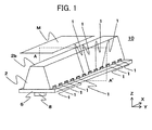
- FIG. 1 is a perspective view of the image reader of Embodiment 1.
- the image reader 10 is a contact image sensor (CIS).
- the X-axis direction illustrated in FIG. 1 indicates the main scanning direction of the image reader 10.
- the Y-axis direction indicates the sub-scanning direction intersecting (at right angle) with the main scanning direction of the image reader 10.
- the sub-scanning direction is a feeding direction in which the object-to-be-read M is fed.
- the Z-axis direction is an axial direction orthogonal to an XY plane defined by the X axis and the Y axis, is also an optical axis direction of the imaging optical system 3 of the image reader 10, and is a reading depth direction that is a direction to indicate the focal depth of the imaging optical system 3.
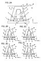
- FIG. 2A is a cross-sectional view of the image reader 10 at a virtual plane AA' that is a parallel plane with an YZ plane defined by the Y axis and the Z axis illustrated in FIG. 1 .
- the virtual plane AA' is a cross-section of a portion that intersects one of the plurality of light-source elements 1 arrayed in the main scanning direction (X-axis direction). Note that the plurality of light-source elements 1 are arrayed in two rows along the main scanning direction (X-axis direction) side-by-side rows sandwiching the imaging optical system 3 therebetween.
- the virtual plane AA' is a cross section that intersects two of the light-source elements 1 disposed respectively in the two rows.
- the virtual plane AA' is a cross section that intersects one of the plurality of light-source elements 1.
- Embodiments 2, 3 and 4, and also this Embodiment 1 are explained for an example configuration in which the light-source elements 1 disposed side by side in the two rows across the imaging optical system 3 are not arranged in the zigzag pattern, but face one another in the sub-scanning direction (Y-axis direction).
- the object-to-be-read M is a reading-target medium (illuminated object) with image information, such as manuscripts, books, magazine pages, documents (general documents), paintings, photographs, transparent positives, rolls of film, banknotes, securities, circuit boards, electronic components and fingerprints.
- FIGS. 2B, 2C and 2D illustrate configurations in which a space (hereinafter, referred to as a "space S") is present between the imaging optical system 3 and the transparent member 2 in the image reader 10 illustrated in FIG. 2A .
- a space S a space
- transparent resin 2r is present in the space S as illustrated in FIGS. 2C and 2D
- the image reader 10 is also presumed to have the space S.
- FIG. 2E illustrates a configuration in which the transparent member 2 of the image reader 10 in FIG. 2A is formed with a below-described cut-out 2n (cut-out portion 2n).
- the cut-out 2n (cut-out portion 2n) exposes the imaging optical system 3 to the object-to-be-read M.
- the space S can be said to be opened.
- the transparent member 2 is a light guide member that is formed, for example, of resin or glass, and that extends in the X-axis direction.
- the transparent member can be also referred to as a light guide.
- light (illumination light) emitted by the light-source elements 1 that are the light source for the image reader 10 is guided through the interior of the transparent member 2, the transparent member 2 is referred to as a light guide 2.
- the image reader 10 includes the light-source elements 1 (light source).
- Embodiment of the present invention discloses only a structure in which the transparent member 2 is the light guide 2, but the present invention is applicable to a configuration in which the light-source elements 1 exist outside the image reader 10, and light from the light-source elements 1 does not enter the interior of the transparent member 2, but rather illuminates directly the object-to-be-read M.
- the reflected light from the object-to-be-read M passes through the interior of the transparent member 2. That is to say, in a configuration in which the transparent member 2 functions by guiding the light from the light source (light-source elements 1) through the interior of the transparent member 2, and by emitting the guided light to the object-to-be-read M, the transparent member can be called "light guide 2".
- the optical path for light from the light source includes a portion formed as the optical path of reflected light of the light guide 2.
- a point light-source element such as an LED (Light Emitting Diode) or an organic EL (Organic Electro Luminescence), is suitable for the light-source element 1 (light source), but the present invention is not limited to the point light source.
- the explanation is given of an example configuration in which the light-source element 1 is an LED.
- a light guide portion 2a of the light guide 2 indicates a part where light from the light source (light-source elements 1) is guided in the light guide 2.
- An object-to-be-read feeding side face 2b of the light guide 2 is, among the surfaces of the light guide 2 (transparent member 2), a surface facing the fed object-to-be-read M.
- the object-to-be-read feeding side face 2b can be understood as a document placement surface 2b.
- the object-to-be-read feeding side face 2b can be understood as the document placement surface 2b.
- the light guide 2 transparent member 2
- the object-to-be-read feeding side face 2b (document placing surface 2b) is completely or partially omitted.
- the object-to-be-read feeding side face 2b (document placing surface 2b) is a virtual surface.
- the object-to-be-read M is not in contact with the virtual surface. The details of the configuration in which the cut-out 2n is formed are explained later.
- the imaging optical system 3 is the lens array assembly 3 which has a plurality of lenses arrayed along the main scanning direction, and which focuses light toward the line sensor assembly.
- the imaging optical system 3 (lens array assembly 3) is constructed by having a plurality of rod lenses (rod lens array) disposed side by side in an array and held between plates
- other lens arrays such as a micro lens array that is the same erecting equal-magnification type optical system as the rod lens array, are applicable. If the micro lens array is used, the imaging optical system 3 becomes a micro lens array assembly 3 that has a plurality of lenses (lens array) held between plates.
- the object-to-be-read feeding side face 2b may have a lens function.
- This lens function can be accomplished by, for example, cutting out a part of the transparent member 2 corresponding to the optical path (a path through which light (including reflected light) travels) of reflected light from the object-to-be-read M and located between the imaging optical system 3 and the object-to-be-read M, and fitting a lens in this cut-out 2n.
- a lens is formed by the object-to-be-read feeding side face 2b, and another lens is fastened to a retainer space 2L of the transparent member 2 in which the imaging optical system 3 is retained.
- the imaging optical system 3 is not limited to the erecting equal-magnification type optical system as long as such a system can be retained in the retainer space 2L of the transparent member 2 or can be formed on the transparent member 2, including the object-to-be-read feeding side face 2b.
- the imaging optical system 3 is provided between the transparent member 2 and the board 6, and in this Embodiment 1, the imaging optical system 3 is fastened to the light shield member 5 arranged between the imaging optical system 3 and the board 6, but may be held on the transparent member 2 by adhesive 21 (adhesive 22), tape and the like, and a wedge member 23 may be pressed in between the transparent member 2 and the imaging optical system 3 to fasten the imaging optical system.
- adhesive 21 adheresive 22
- the optical axis of the imaging optical system 3 is disposed so as to be perpendicular to the reading surface (document surface) of the object-to-be-read M, and the imaging optical system 3 has a function of forming an image on a sensor IC 4 that is a light receiver assembly for focusing reflected light from the object-to-be-read M.
- the sensor IC 4 is the line sensor assembly 4 (can be referred to as a sensor array assembly 4) that has a plurality of photosensitive elements formed along the main scanning direction on one surface of the board 6.
- the sensor IC 4 receives light focused by the imaging optical system 3, performs photoelectric conversion, and outputs electric signals.
- On the sensor IC 4 is mounted a light receiver assembly composed of a semiconductor chip, other drive circuits and the like. These mounted components are arranged on the one surface of the board 6, the other surface thereof and in the interior thereof.
- the light shield member 5 supports a portion of the imaging optical system 3 at the sensor-IC-4 side, and functions as a light shield 5 that blocks light other than light focused by the imaging optical system 3.
- the light shield member 5 disposed between the board 6 and the imaging optical system 3 is provided with a structure having an opening having a certain length in the sub-scanning direction at least a length so as to surround the photosensitive elements of the sensor IC 4, and penetrating in the direction orthogonal to the main scanning direction and the sub-scanning direction, that is, penetrating in the optical axis direction (Z-axis direction) and extending in the main scanning direction.
- the light shield member 5 has a function of blocking light entering to the sensor IC 4 from the exterior of the above-described image reader 10.
- the light shield member 5 is preferably formed of a black resin having a low reflectivity or an anodized material so that light passing through the imaging optical system 3 but not entering to the sensor IC 4 and scattered and reflected by the board 6 and further reflected by the surrounding components does not enter the sensor IC 4.
- the light shield member 5 has a dust-proofing effect in that foreign materials are prevented from entering to the sensor IC 4.
- the dust-proofing effect of the light shield member 5 is explained for configurations using another component (dust-proofing member 7).
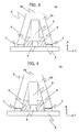
- FIGS. 3 and 4 are cross-sectional views of the image reader 10 at the YZ plane (virtual plane) defined by the Y axis and the Z axis as in FIGS. 2A to 2E , and are each a cross-sectional view of a part where the light-source elements 1 are disposed.
- end portions of the transparent member 2 which are surfaces arranged opposite to the retainer space that retains the imaging optical system 3 and that are located at the opposite side to the object-to-be-read M, protrude and are in contact with the board 6 along the main scanning direction at both of the front and the back in the sub-scanning direction.
- the protruding portions of the transparent member 2 illustrated in FIG. 3 can accomplish the dust-proofing function.
- the sensor IC 4 can be protected from dust even if the dust-proofing function of the light shield member 5 alone is deficient.
- the protruding portions of the transparent member 2 have the dust-proofing function, the light-source elements 1 are also protected from dust.
- the end portions of the transparent member 2 opposite to the object-to-be-read M extend between the plurality of light-source elements 1 (light source array) disposed as an array and the light shield member 5, and are in contact with the board 6 along the main scanning direction.
- the extended portions of the transparent member 2 illustrated in FIG. 4 can accomplish the dust-proofing function.
- the sensor IC 4 can be protected from dust even if the dust-proofing function of the light shield member 5 alone is deficient.
- a combination of the protruding portions of the transparent member 2 illustrated in FIG. 3 and in FIG. 4 may be employed.
- Electronic components such as the light-source elements 1, the sensor IC 4, an external connector 8 and a signal processor IC 11 such as an IC using an ASIC (Application Specific Integrated Circuit) are mounted on the board 6.
- the signal processor IC 11 performs signal processing on, for example, the photoelectric conversion output received through the sensor IC 4.
- the CPU 12a, the RAM 12b and a signal processing circuit 12c in the signal processor IC 11 are collectively referred to as a signal processor 12.
- the external connector 8 is utilized as an input/output signal interface for the photoelectric conversion output by the sensor IC 4, and other signal processing outputs.
- FIG. 5 is an illustrated parts breakdown (exploded oblique drawing) of the image reader according to Embodiment 1.
- the image reader according to Embodiment of the present invention includes the transparent member 2, the imaging optical system 3 and the sensor IC 4, which have lengths equal to or greater than the effective reading width of the object-to-be-read M (effective reading width in main scanning direction).
- the reference sign of the light-source elements 1 is indicated only for the light-source elements (in the figure, four elements) disposed at the ends in the main scanning direction (X-axis direction) of the light source, and such indication is omitted for the other elements.
- the transparent member 2 retains the imaging optical system 3 and the light shield member 5 in the retainer space, and covers a part of the imaging optical system 3 at the object-to-be-read-M side and the light shield member 5.
- fasteners of the image reader 10 of the present invention engagement portion 2c, engagement portion 2d, boss 2e, screw 9, clip 16, clip 17, adhesive 18, and elastic member 19
- fasteners of the image reader 10 of the present invention fasten the transparent member 2 to the board 6, and the pressing force from the board 6 by this fastening causes the light shield member 5 and the imaging optical system 3 to be in contact with the transparent member 2.
- the fasteners of the image reader 10 of the present invention can fasten the transparent member 2 to the board 6, and the pressing force from the board 6 by this fastening can bring the light shield member 5 into contact with the transparent member 2.
- the transparent member 2 can be fastened to the board 6, and the pressing force from the board 6 by this fastening can cause the imaging optical system 3 to be in contact with the transparent member 2 via the light shield member 5.
- the illustration of the image reader 10 in such a configuration is omitted.
- the engagement portion 2c is explained later with reference to FIGS. 6 to 9 .
- the engagement portion 2d, boss 2e, screw 9, clip 16, clip 17, adhesive 18, and the elastic member 19 are explained in Embodiment 5.
- the fastener may be understood as a fastener that further includes a part of the transparent member 2 or the board 6 related to the fastening of the transparent member 2 with the board 6 by the engagement portion 2c, engagement portion 2d, boss 2e, screw 9, clip 16, clip 17, adhesive 18 and elastic member 19.
- the space S can be formed between the portion of the transparent member 2 through which reflected light from the object-to-be-read M passes and a portion of the imaging optical system 3 facing that portion (tip of imaging optical system 3 at object-to-be-read-M side).
- Fresnel reflection can be caused when reflected light from the object-to-be-read M travels to the space S from the transparent member 2. If such reflection occurs, Fresnel reflection can be suppressed if the space S is filled as in the image reader 10 illustrated in FIG. 2C with a transparent resin 2r, i.e. a resin having transparency (suitably having the same or similar refraction index as that of the transparent member 2).
- a transparent resin 2r i.e. a resin having transparency (suitably having the same or similar refraction index as that of the transparent member 2).
- the space S is filled beforehand with the transparent resin 2r, like the image reader 10 illustrated in FIG. 2D , it is unnecessary to cause the transparent member 2 to be contacted with only the plate supporting the plurality of lenses in the imaging optical system 3 or the plate and the portion of the imaging optical system 3 that is not optically functional.
- the example image reader 10 according to Embodiment 6 illustrates a configuration in which the adhesive 21 is applied as the transparent resin 2r to fasten the imaging optical system 3 to the transparent member 2.
- the transparent member 2 can be brought into contact with only the plate supporting the plurality of lenses in the imaging optical system 3 or the plate and the portion of the imaging optical system 3 that is not optically functional, and the imaging optical system 3 may be fastened to the transparent member 2 using the below-described adhesive 21.
- the transparent resin 2r can be non-transparent, such as a colored resin having a light shielding function.
- the Fresnel reflection can be suppressed by, not filling the space S with the transparent resin 2r but rather by using a transparent member 2 having a cut-out portion, which is a portion between the imaging optical system 3 and the object-to-be-read M and which is the optical path of reflected light from the object-to-be-read M, and by opening the space S through this cut-out 2n.
- the cut-out 2n (cut-out portion 2n) is preferably tapered so as to decrease in width toward the imaging optical system 3 from the object-to-be-read M.
- the tapered structure can reduce the reflection (scattered reflection) of the reflected light from the object-to-be-read M in the cut-out portion 2n.
- a black resin of low reflectivity or adonization of the surface of the cut-out portion 2n may be used to accomplish the light shielding effect.
- the transparent member 2 brought into contact with, in the main scanning direction (X-axis direction), only the plate supporting the plurality of lenses in the imaging optical system 3 or the plate and the portion of the imaging optical system 3 that is not optically functional.
- the transparent member 2 may be brought into contact with, in the sub-scanning direction (Y-axis direction), only the plate supporting the plurality of lenses in the imaging optical system 3 or the plate and the portion of the imaging optical system 3 that is not optically functional.
- the transparent member 2 is brought into contact with, in the sub-scanning direction, the plate in the imaging optical system 3 and the portion of the imaging optical system 3 that is not optically functional or, the portion of the imaging optical system 3 that is not optically functional. Needless to say, the transparent member 2 can be brought into contact with the imaging optical system 3 in both main scanning direction and sub-scanning direction.
- the cut-out 2n may be tapered, but when a technology for "causing the object-to-be-read feeding side face 2b to have a lens function" is applied to the tapered cut-out 2n, a lens is fitted in the cut-out 2n.
- the tapered cut-out 2n may decrease in width toward the object-to-be-read M from the imaging optical system 3, which is a change in width opposite to that of the above explanation.
- the cut-out 2n when the lens is fastened to the cut-out 2n, the cut-out 2n does not need to be tapered.
- the cut-out 2n may be formed with a stepped portion, and the lens may be fastened thereto.
- the space S and the cut-out 2n including the tapered cut-out
- the space S and the cut-out 2n can be formed in the transparent member 2.
- FIGS. 6 to 9 illustrate example methods of fastening (fasteners) the transparent member 2 to the board 6.
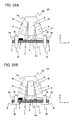
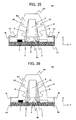
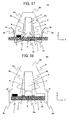
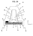
- FIGS. 6 and 7 illustrate a configurations in which multiple protrusions with respective barbs for fastening the board, that is, the engagement portions 2c (fasteners) are provided at several locations of the transparent member 2 at the board-6 side.
- FIG. 6 is a cross-sectional view of FIG. 7 . More specifically, FIG. 6 is a cross-sectional view at the YZ plane (virtual plane) defined by the Y axis and the Z axis in the image reader 10 in FIG. 7 , and is a cross-sectional view of a portion where the light-source elements 1 are disposed.
- YZ plane virtual plane
- the protrusion is preferably divided into several portions and formed at several locations in the main scanning direction. More specifically, a total of eight fasteners are formed, four at each side, in the main scanning direction in FIGS. 6 and 7 .
- the engagement portions 2c (fasteners) illustrated in FIGS. 6 and 7 can be understood as the fasteners that hold and fasten the board 6.
- the engagement portions 2c (fasteners) in FIGS. 6 and 7 are formed integrally with the transparent member 2. Needless to say, the engagement portions 2c (fasteners) may be separate components from the transparent member 2.
- FIG. 8 is a cross-sectional view at the YZ plane (virtual plane) defined by the Y axis and the Z axis in the image reader 10 as in FIGS. 2 and 6 , but is a cross-sectional view of a portion where no light-source element 1 is disposed.
- FIG. 8 corresponds to a configuration in which a hole (multiple holes) is formed between the adjoining light-source elements 1 disposed side by side in an array along the main scanning direction, that is, formed in areas where no light-source element 1 is disposed at the board-6 side, and protrusions (engagement portions 2c) are formed at the portions of the transparent member 2 at the board-6 side facing the respective holes.
- the protrusions (engagement portions 2c) of the transparent member 2 are melted and fusion bonded.
- the fasteners are portions that pass through the board 6 and are fusion bonded.
- the screws are inserted in the screw holes of the transparent member 2 through the holes of the board 6 from the other surface side thereof, and are tightened.
- a set of the screw and the screw hole can be referred to as the engagement portion 2c (fastener) rather than only referring to the screw as the engagement portion 2c (fastener), and the three members that are the screw, the hole (of the board 6) and the screw hole can be collectively referred to as the engagement portion 2c (fastener).
- the engagement portions 2c (fasteners) illustrated in both FIGS. 8 and 9 pass through the board 6 and fasten the board.
- the engagement portions 2c (fasteners) in FIG. 8 are formed integrally with the transparent material 2. Needless to say, the engagement portions 2c (fasteners) in FIG. 8 can be separate parts from the transparent member 2. In addition, the forms of the engagement portions 2c (fasteners) illustrated in FIGS. 8 and 9 can be combined.
- the engagement portions 2c (fasteners) in FIG. 9 that is, portions where the screws are applied to position accurately the transparent member 2 and the board 6 relative to one another, and after this accurate positioning, the engagement portions 2c (fasteners) in FIG. 8 can be fusion bonded. This can facilitate the assembly of the image reader 10.
- the respective forms of the engagement portions 2c (fasteners) in FIGS. 8 and 9 can be combined with the form of the engagement portion 2c illustrated in FIG. 6 (or FIG. 7 ).
- FIG. 10A is a functional block diagram of the image reader 10 of Embodiment 1.
- FIG. 10A illustrates an example configuration in which the signal processor IC 11 is an ASIC 11. Firstly, in conjunction with the CPU 12a, the ASIC 11 transmits a light-source turn-on signal to a light-source drive circuit 1d.
- the light-source drive circuit 1d supplies power for a predetermined time to each of the plurality of light-source elements 1 based on the received light-source turn-on signal. Illumination light emitted by the light-source elements 1 enters the interior of the transparent member 2 (light guide 2), is transmitted or reflected repeatedly, and is emitted to the object-to-be-read M.
- the image reader 10 may drive and control the light-source elements 1 even in a configuration in which the light-source elements 1 are located outside the image reader 10 or in which light from the light-source elements 1 does not enter the interior of the transparent member 2 but rather is emitted directly to the object-to-be-read M.
- the light reflected by the object-to-be-read M is focused on the sensor IC 4 by the imaging optical system 3.
- the sensor IC is a light receiver assembly (photosensitive elements) including, for example, a semiconductor chip that receives the focused light, performs photoelectric conversion, outputs electric signals, and is equipped with other drive circuits and the like.
- the light receiver assembly obtains an analog output (SO) having undergone photoelectric conversion at the timing of a start signal (SI) synchronized with a clock signal (CLK) of the CIS and in synchronization with a system clock (SCLK) of a timing generator.
- An example SO is indicated in the graph of FIG. 10B . In this graph, an output value is plotted along the vertical axis, and time (t: Time) is plotted along the horizontal axis.
- the CPU 12a, the RAM 12b and the signal processing circuit 12c in the ASIC 11 are collectively referred to as a signal processor 12.
- the SO is subjected to analog to digital (A-D) conversion by an A-D converter 13, and the signal processing circuit 12c performs shading correction including processing such as sample holding and all-bit correction.
- A-D analog to digital
- the signal processing circuit 12c performs shading correction including processing such as sample holding and all-bit correction.
- data is acquired from a RAM area storing signal data and from a RAM area storing reference data, and after mathematical processing, the image data of the object-to-be-read M is output as digital output (SIG).
- This image data can be transmitted to a device external to the image reader 10, or can be subjected to a further image processing in the image reader 10, and then can be transmitted to the external device.
- An example SIG is illustrated in the graph of FIG. 10C (256 digit). The output value of this graph is plotted along the vertical axis, and time (as a line segment) is plotted along the horizontal axis. This type of plot is obtained because the image reader 10 is a line sensor. That is to say, the image reader 10 reads the object-to-be-read M line by line in the main scanning direction, and the object-to-be-read M is fed in the sub-scanning direction for scanning of the next line.
- FIG. 11 the path (optical path) is explained through which illumination light emitted by the light-source elements 1 enters the transparent member 2 (light guide 2) and is repeatedly transmitted and reflection therein to be emitted to the object-to-be-read M, among the operations of the image reader of Embodiment 1.
- the image reader 10 illustrated in FIG. 11 employs the same structure as that of the image reader 10 in FIGS. 2A to 2E , and FIG. 11 illustrates a portion of the path for illumination light from the light-source elements 1.
- the figures of the present invention including FIG. 11 illustrate light entering from the array of light-source elements 1 arrayed along the main scanning direction (X-axis direction) at one side of the light guide portion 2a. In the figure, the path for light (optical path) is illustrated at the left portion of the light guide portion 2a.
- the path for illumination light from the light-source elements 1 reflects light at least two times by, in the light guide portion 2a of the light guide 2, the internal surface at the imaging-optical-system-3 side (hereinafter, referred to as the "internal side face of the light guide portion 2a"), and an external surface that is an opposite surface to this internal surface (hereinafter, referred to as the "external side face of the light guide portion 2a") to illuminate the object-to-be-read M or to propagate in the main scanning direction (X-axis direction).
- the major path includes a first path 13a in which the light is reflected at least two times by the internal side face of the light guide portion 2a and the external side face thereof without illuminating the object-to-be-read M, and a second path 13b in which the light is reflected once by the external side face of the light guide portion 2a to illuminate the object-to-be-read M by the reflected light.
- the first path 13a is a light path for the transmission of light without reflection by the light guide portion 2a in the light guide 2. In the figure, this light path is indicated by a thick line.
- the second path 13b is a reflective optical path that reflects the light once by the light guide portion 2a in the light guide 2, and then allows the light to propagate. In the figure, this optical path is indicated by a dotted line.
- the transparent member 2 (light guide 2) includes both end faces in the main scanning direction (X-axis direction) of the transparent member 2 (light guide 2), the internal side face of the light guide path 2a, the external side face thereof, the object-to-be-read feeding side face 2b and a surface that faces the object-to-be-read feeding side face 2b in the optical-axis direction (Z-axis direction) of the imaging optical system 3, and that allows reflected light from the object-to-be-read M to pass through the object-to-be-read feeding side face 2b and emits the light to the imaging optical system 3 through the transparent member 2 (light guide 2).
- the surface that emits light from the transparent member 2 (light guide 2) to the imaging optical system 3 can be understood as a part of the internal side face of the light guide portion 2a.
- the first path 13a illustrated in FIG. 11 is a path in which light emitted by the light-source elements 1 passes through the incident surface of the transparent member 2, travels in the light guide portion 2a, passes through the object-to-be-read feeding side face 2b (is emitted from the object-to-be-read feeding side face 2b), and reaches directly the object-to-be-read M.
- the second path 13b illustrated in FIG.11 is a path in which light emitted from the light-source elements 1 in the direction perpendicular to the object-to-be-read M is reflected once by the external side face of the light guide portion 2a in the light guide 2, travels in the light guide portion 2a, passes through the object-to-be-read feeding side face 2b (is emitted from the object-to-be-read feeding side face 2b), and reaches the object-to-be-read M.
- n is the refractive index of the transparent member 2
- ⁇ is the inclination of the light guide portion 2a of the transparent member 2. Note that as illustrated in FIG. 11 , ⁇ is the narrower angle of the two angles at the YZ plane defined by an intersection of a line parallel to the Z-axis direction (a line indicated by two-dot chain line as an auxiliary line) with the external side face of the light guide portion 2a.
- first path 13a is included in the above-defined paths.
- the second path 13b indicates only the path propagating along the YZ plane.
- the inclination ⁇ of the light guide portion 2a is preferably set to be equal to or smaller than 7.4° so as to satisfy the Formula (1).
- the thickness of the transparent member 2 (light guide 2) in the Y-axis direction from the internal side face of the light guide portion 2a to the external side face thereof is uniform except for a portion transmitting reflected light from the object-to-be-read M. Accordingly, light reflected totally by the surface of the light guide portion 2a enters another surface of the light guide portion 2a at the same angle, and continues propagating in the transparent member 2 by total reflection.
- the light guide portion 2a of the transparent member 2 has uniform thickness in the Y-axis direction except the portion transmitting reflected light from the object-to-be-read M, but in order to promote total reflection in the light guide portion 2a, a structure may be employed in which the light guide 2a of the transparent member 2 becomes thicker as the surface of the light guide portion 2a is approached to the object-to-be-read M.
- the image reader of Embodiment 1 employs a structure in which light is guided to the object-to-be-read M by total reflection.
- the selected value of the inclination ⁇ of the light guide portion 2a is small.
- the path that is the first path 13a, among the major paths for light emitted by the light-source elements 1, intersects the imaging optical system 3, and becomes a path in which light is reflected two or more times by the internal side face of the light guide portion 2a and the external side face thereof.
- the imaging optical system 3 is required to be disposed at a location out of a virtual plane through which pass two virtual lines, i.e. a first virtual line that passes through the array of intersection points of the optical axes of the plurality of lenses forming the imaging optical system 3 with the object-to-be-read M, and a second virtual line passing through the array of the disposed plurality of light-source elements 1.
- the virtual plane is a plane orthogonal to the YZ plane, and among the lines of intersection between the virtual plane and the YZ planes, one line within the transparent member 2 (light guide 2) is the first path 13a.
- the first virtual line and the second virtual line are virtual lines parallel to the main scanning direction (X-axis direction).
- the second virtual line passing through the array of the disposed plurality of light-source elements 1 passes through a portion where the light-source elements 1 emit light.
- FIG. 12 is a cross-sectional view of an image reader according to Embodiment 2.
- FIG. 12 is a cross-sectional view of the image reader 10 at a plane parallel to the YZ plane defined by the Y axis and Z axis. More specifically, this is a cross-sectional view of a portion that intersects one of the plurality of light-source elements 1 arrayed in the main scanning direction (X-axis direction).
- this figure illustrates a configuration in which the plurality of light-source elements 1 are disposed in two rows positioned facing each other in the sub-scanning direction (Y-axis direction).
- the two light-source elements 1 can be seen to sandwich the sensor IC 4.
- "plurality of light-source elements 1 disposed in two rows” may be expressed as a "light source array in two rows” or a "two row light source array” in some cases.
- the same or equivalent component in FIG. 11 used to explain Embodiment 1 is denoted by the same reference sign, and repeated explanation is omitted.
- the image reader 10 illustrated in FIG. 12 indicates a portion of the path for illumination light from the light-source elements 1.
- the major path for illuminating the object-to-be-read M includes the first path 13a in which light is reflected at least two times by the internal side face of the light guide portion 2a and the external side face thereof without illuminating the object-to-be-read M, and the second path 13b in which light is once reflected by the light guide portion 2a and illuminates the object-to-be-read M.
- the external side face of the light guide portion 2a of the transparent member 2 (light guide 2) in the image reader of Embodiment 1 is formed as a mirror surface 14.
- the mirror surface 14 of the transparent member 2 (light guide 2) is a portion of the profile of the transparent member 2 indicated by a thick line.
- the mirror surface 14 can be formed on the external side face of the light guide portion 2a by metal vapor deposition, metal plating, or by placing a metal tape.
- the mirror surface 14 is formed at a portion where illumination light traveling in the Z-axis direction among light emitted by the light-source elements 1 falls on the light guide 2.
- the mirror surface 14 is formed at a part where the virtual line parallel to the Z-axis and passes through the portion of the light sources emitting light intersects the light guide 2. It can be also understood that, when the transparent member 2 includes a below-described reflection area 15, the mirror surface 14 is formed at a portion where a virtual line parallel to the Z-axis and passing through the reflection area 15 intersects the light guide 2.
- the image reader of Embodiment 1 employs a structure in which light is guided to the object-to-be-read M by total reflection.
- the value of the inclination ⁇ of the light guide portion 2a tends to be small. Accordingly, the smaller the inclination ⁇ of the light guide portion 2a, the shorter the distance between the light-source element 1 and the sensor IC 4 in Y-axis direction.
- the package of the light-source elements 1 when the package of the light-source elements 1 is large, only a layout that causes the sensor IC 4 to be in contact with such a package can be selected for some configurations. Needless to say, the space for arranging the light shield member 5 is also lost.
- the sensor IC 4 is required to be mounted on the board 6 in such a way that the light-source elements 1 do not interfere with the sensor IC 4, that is, the inclination ⁇ of the light guide portion 2a may be larger than the value obtained by the Formula (1), and thus the total reflection condition for light incident to the light guide portion 2a of the light guide 2 cannot be satisfied.
- the mirror surface 14 is formed on the external side face of the light guide portion 2a of the transparent member 2 (light guide 2).
- the object-to-be-read M is also illuminated mainly by the first path 13a and the second path 13b. Since the external side face of the light guide portion 2a is formed as the mirror surface 14, light incident on the mirror surface 14 inevitably is reflected regularly.
- the image reader 10 including the mirror surface 14 does not need to satisfy the condition of the Formula (1), explained in Embodiment 1, for propagating light to the object-to-be-read feeding side face 2b by total reflection in the light guide portion 2a.
- Light guided by the light guide portion 2a is emitted (output) as illumination light from the object-to-be-read feeding side face 2b of the transparent member 2 (light guide 2).
- FIG. 13 is a cross-sectional view of the image reader according to Embodiment 2.
- FIG. 13 is the cross-sectional view of the image reader 10 at a plane parallel to the YZ plane defined by the Y-axis and the Z-axis like FIG. 12 . More specifically, this is a cross-sectional view of a portion that intersects one of the plurality of light-source elements 1 arrayed in the main scanning direction (X-axis direction).
- FIG. 13 illustrates a configuration in which the plurality of light-source elements 1 are arranged as two rows at positions in the sub-scanning direction (Y-axis direction), and thus the two light-source elements 1 can be seen to sandwich the sensor IC 4 in this figure.
- the same or equivalent components as those in FIGS. 12 and 11 used to explain Embodiment 1 are denoted by the same reference signs, and repeated explanation of such components is omitted.
- the incident angle at this time can be determined according to the above-explained inclination ⁇ of the light guide portion 2a.
- the inclination ⁇ of the light guide portion 2a is indicated as " ⁇ 2 ", but the definition thereof is the same.
- ⁇ 2 is the narrower angle of two angles in the YZ plane defined by an intersection of a line parallel to the Z-axis direction (line indicated by two-dot chain line as an auxiliary line) with the external side face of the light guide portion 2a.
- the intersection angle of light reflected by the mirror surface 14 with the Z-axis that is, the incident angle of light reflected totally by the mirror surface 14 toward the object-to-be-read feeding side face 2b is 2 ⁇ 2 .
- a condition in which light reflected by the mirror surface 14 is not reflected totally by the object-to-be-read feeding side face 2b can be defined as the following Formula (2).
- the incident angle 2 ⁇ 2 is an intersection angle of the virtual line parallel to the Z-axis direction (line indicated by two-dot chain line orthogonal to the object-to-be-read feeding side face 2b) with illumination light reflected totally by the mirror surface 14 onto the object-to-be-read feeding side face 2b.
- the virtual line parallel to the Z-axis direction corresponds to the optical axis of the imaging optical system 3 (optical-axis direction).
- the two-dot chain line orthogonal to the mirror surface 14 indicates a position where light passing through the second path 13b is reflected by the mirror surface 14.
- the incident angle toward the object-to-be-read feeding side face 2b in the first path 13a is smaller than that of the second path 13b, and thus when the inclination (angle) ⁇ 2 of the light guide portion 2a satisfies the Formula (2), the first path 13a also does not cause total reflection.
- the condition of the Formula (1) explained in Embodiment 1 is included in the Formula (2), and thus no total reflection occurs when light passing through the first path 13a of the light guide portion 2a and the second path 13b thereof in the image reader of Embodiment 1 enters the object-to-be-read feeding side face 2b.
- Embodiment 2 only the external side face of the light guide portion 2a is formed as the mirror surface 14, but the internal side face of the light guide portion 2a at the imaging-optical-system-3 side (except for "the surface that faces the object-to-be-read feeding side face 2b in the optical-axis direction (Z-axis direction) of the imaging optical system 3, and that allows reflected light from the object-to-be-read M to pass through the object-to-be-read feeding side face 2b to emit such light toward the imaging optical system 3 from the transparent member 2 (light guide 2)) can be also formed as the mirror surface 14.
- the transparent member 2 can be formed with fasteners of the image reader of Embodiment 1 (engagement portion 2c, engagement portion 2d, boss 2e, boss 2f and engagement portion 2g), and this transparent member 2 (light guide 2) can be connected to the board 6.
- the details of such fasteners are the same as those of Embodiment 1. That is to say, the image reader of Embodiment 2 can be said to be the image reader of Embodiment 1 equipped with the mirror surface 14.
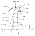
- FIGS. 14 , 15A , 16 , 17A , 18 , 19A , 20 and 21A are each a cross-sectional view of an image reader of Embodiment 3.
- FIGS. 14 , 15A , 16 , 17A , 18 , 19A , 20 and 21A are each a cross-sectional view of an image reader 10 at the plane that is parallel to the YZ plane defined by the Y axis and the Z axis. More specifically, these are cross-sectional views of a portion that intersects one of the plurality of light-source elements 1 disposed side by side in the main scanning direction (X-axis direction).
- FIGS. 14 , 16 , 18 and 20 are cross-sectional views of a portion having no fasteners, such as the engagement portion 2c, engagement portion 2d, boss 2e, boss 2f and engagement portion 2g.
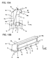
- FIGS. 15A , 17A , 19A and 21A illustrate the engagement portion 2c as an example fastener.
- the same or equivalent component is denoted by the same reference sign, and repeated explanation is omitted.
- FIGS. 15B , 17B , 19B and 21B are oblique drawings of the image reader 10 illustrated in FIGS. 15A , 17A , 19A and 21A , respectively.
- FIGS. 15A, 15B , 17A, 17B , 19A, 19B , 21A and 21B a total of eight fasters (engagement portions 2c) are formed, four at each side, in the main scanning direction, and the transparent member 2 is in contact with the light shield member 5 (light shield 5) at locations where no fastener is formed.
- FIG. 14 , 16 , 18 and 20 the transparent member 2 is not in contact with the light shield member 5 (light shield 5) at a portion where no fastener is formed.
- These figures illustrate configurations in which the transparent member 2 and the fasteners are integrated with each other. These components may be formed separately. In these figures, the same or equivalent component is denoted by the same reference sign, and repeated explanation thereof is omitted.
- FIGS. 14 , 15A , 16 , 17A , 18 , 19A , 20 and 21A illustrate an optical path (path for light) in the image reader of Embodiment 3.
- the light source array which is disposed in two rows in Embodiments 1 and 2, is arranged in one row.
- the transparent member 2 of the image reader of Embodiment 3 is shaped so as to expose one of the respective two side faces of the imaging optical system 3 (lens array assembly 3) and the light shield member 5 (light shield 5) along the main scanning direction (see FIGS.
- FIGS. 15A, 15B , 17A, 17B , 19A, 19B , 21A and 21B is shaped so as to expose one of the two side faces of the imaging optical system 3 (lens array assembly 3) along the main scanning direction (see FIGS. 15A, 15B , 17A, 17B , 19A, 19B , 21A and 21B ).
- the virtual line parallel to the Z-axis direction (line indicated by two-dot chain line orthogonal to the object-to-be-read feeding side face 2b) orthogonal to the object-to-be-read feeding side face 2b illustrated in FIGS. 14 , 15A , 16 , 17A , 18 , 19A , 20 and 21A corresponds to the optical axis of the imaging optical system 3.
- the engagement portions 2c can also be protrusions running in the main scanning direction, rigidity of the protrusions is increased, and the board 6 might not be held well.
- the protrusion can be divided into multiple pieces and formed at several locations in the main scanning direction.
- a portion of which the imaging optical system 3 (lens array assembly 3) is exposed is a plate holds the lens array of the imaging optical system 3 (lens array assembly 3).
- the image reader of Embodiment 3 has built-in light-source elements 1, and the light-source array including the light-source elements 1 is arranged in one row. Hence, when illumination light propagates mainly through the first path 13a and the second path 13b, which are explained in Embodiments 1 and 2, and then is emitted to the object-to-be-read M, the reading position of the imaging optical system 3 is irradiated (illuminated) by only illumination light from one sub-scanning direction (Y-axis direction) side.
- the reading position of the imaging optical system 3 may be illuminated by illumination light from the one sub-scanning direction (Y-axis direction) side, but if the object-to-be-read M is non-planar and is illuminated from only the one side, shadows can be generated on the object-to-be-read M due to non-flatness, and the shadows can be generated in the read image (image data).
- the image data of the object-to-be-read M output by the image reader 10 (signal processing circuit 12c) is utilized for determination of whether the banknote or security is counterfeit or not.
- irregular shadows being generated due to the non-flatness in the data of a particular image in other words, for each banknote (security), can adversely affect the determination of counterfeit status of the banknote or security.
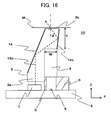
- illumination by illumination light from both sides in the sub-scanning direction can be accomplished by a structure that includes the mirror surface 14, a mirror surface 14a and a mirror surface 14b of the image reader 10 illustrated in FIG. 14 .
- a structure that includes the mirror surface 14, a mirror surface 14a and a mirror surface 14b of the image reader 10 illustrated in FIG. 14 .
- the configuration of the image reader 10 illustrated in FIG. 14 is explained below.
- illumination light traveling a second path 13c (in the figure, indicated by a dashed line) is reflected in order by the mirror surface 14, the object-to-be-read feeding side face 2b, the mirror surface 14a and the mirror surface 14b, that is, reflected multiple times, and illumination light traveling the first path 13a and illumination light traveling the second path 13c are emitted from the object-to-be-read feeding side face 2b at both sides of the reading position of the imaging optical system 3, and thus illumination lights are emitted from opposite directions to each other in the sub-scanning direction.
- the image reader of Embodiment 3 has the "mirror surface 14, mirror surface 14a and mirror surface 14b” , the “mirror surface 14, mirror surface 14c”, or the “mirror surface 14d, mirror surface 14a and mirror surface 14b" formed on the external side faces of the light guide portion 2a of the transparent member 2 (light guide 2).
- the mirror surface 14a, mirror surface 14b, mirror surface 14c and mirror surface 14d can be formed on the external side face of the light guide portion 2a by metal vapor deposition, metal plating, or placement of a metal tape. It can be understood that, like Embodiment 2, the mirror surface 14 of Embodiment 3 is formed at a portion where the virtual line parallel to the Z-axis and passing through the portion of the light-source element 1 emitting light intersects the light guide 2.
- the mirror surface 14d is formed at, including a portion where the virtual line parallel to the Z-axis and passing through the portion of the light-source element 1 emitting light intersects the light guide 2, a portion where the optical axis of light emitted by the light-source element 1 intersects the light guide 2.
- the transparent member 2 has the below-described reflection area 15
- the mirror surface 14d can be said to be formed at a portion where the optical axis of reflected light by the reflection area 15 intersects the light guide 2.
- the mirror surface 14, mirror surface 14a and mirror surface 14b of the transparent member 2 are portions of the outline of the transparent member 2 indicated by thick lines. Irradiation (illumination) of the reading position of the imaging optical system 3 by illumination light from both sides in the sub-scanning direction (Y-axis direction) is explained in detail for the first path 13a, second path 13c and second path 13b explained in Embodiment 2.
- illumination light through the second path 13b is reflected by the mirror surface 14 of the light guide 2 which has the inclination ⁇ ( ⁇ 2 ) condition thereof set so that illumination light is not reflected totally at the object-to-be-read feeding side face 2b as defined by the Formula (2) (Formula (3) when the refractive index of the transparent member 2 is 1.5), thereby emitting the light from the object-to-be-read feeding side face 2b.
- the mirror surface 14 which is located at a position facing the light source of the image reader in FIG. 14 and which reflects illumination light from the light-source elements, is required to have an angle set so as to cause total reflection by the object-to-be-read feeding side face 2b, contrary to Embodiment 2. That is to say, the inequality sign and the condition defined by the Formula (2) (Formula (3) when the refractive index of the transparent member 2 is 1.5) is required to be reversed for the inclination ⁇ ( ⁇ 2 ) of the light guide 2 (light guide portion 2a) formed with the mirror surface 14.
- Illumination light reflected totally by this object-to-be-read feeding side face 2b is reflected totally by the mirror surface 14a, and is further reflected totally by the mirror surface 14b, is emitted from the object-to-be-read feeding side face 2b, and is emitted to the object-to-be-read M.
- the mirror surface 14a is disposed at a position facing the mirror surface 14 in the sub-scanning direction (Y-axis direction), and illumination light reflected totally by the mirror surface 14 and also reflected totally by the object-to-be-read feeding side face 2b is reflected totally in the opposite direction to the object-to-be-read M.
- the mirror surface 14b is a surface of the light guide 2 (light guide portion 2a) that is parallel to the XY plane, and is contiguous with the mirror surface 14a.
- the mirror surface 14a and the mirror surface 14b are adjusted (as may be required, the mirror surface 14 can also be adjusted) in such a way that the incident angle of illumination light to the object-to-be-read feeding side face 2b, which is reflected totally by the mirror surface 14b and which travels toward the object-to-be-read feeding side face 2b, satisfies the same condition as the incident angle 2 ⁇ (2 ⁇ 2 ) of the first path 13a explained in Embodiments 1 and 2, illumination light that travels through the second path 13c, and enters the object-to-be-read feeding side face 2b after being reflected by the mirror surface 14b, is not reflected totally.
- the mirror surface 14b may not be parallel to the XY plane.
- the incident angle 2 ⁇ 2 in this case is an intersection angle of, on the object-to-be-read feeding side face 2b, the virtual line (two-dot chain line) that is parallel to the Z-axis direction with illumination light reflected totally by the mirror surface 14b.
- the first path 13a for traveling illumination light is, as in Embodiments 1 and 2, the path where incident light to the transparent member 2 (light guide 2) passes through the transparent member and illuminates directly the object-to-be-read M.
- the second path 13c after entering the transparent member 2 (light guide 2), light is reflected by the external mirror surface 14 of the light guide portion 2a, is reflected totally by the object-to-be-read feeding side face 2b of the transparent member 2, is further reflected by the multiple mirror surfaces 14a and 14b placed at the opposite side of the transparent member 2 (light guide 2) across the optical axis of the imaging optical system 3, and then illuminates the object-to-be-read M.
- the imaging optical system 3 is preferably disposed at a location out of the virtual plane through which two virtual line pass, the first virtual line passing through the array of intersection points of the respective optical axes of the plurality of lenses constructing the imaging optical system 3 with the object-to-be-read M, and the second virtual line passing through the array of the plurality of disposed light-source elements 1.
- the virtual line formed by the intersection of this virtual plane with the YZ plane corresponds to the first path 13a.
- FIGS. 15A and 15B illustrate a configuration in which protrusions with respective barbs to fasten the board, that is, the engagement portions 2c (fasteners) as explained in Embodiment 1 and illustrated in FIGS. 6 and 7 , are provided at multiple locations of the transparent member 2 at the board-6 side. Needless to say, the light-source elements 1 are not required to face the engagement portions 2c in the sub-scanning direction.
- FIGS. 15A and 15B a total of eight fasteners are formed, four at each side, in the main scanning direction.
- the transparent member 2 is exposed at one face of the two side faces along the main scanning direction of the imaging optical system 3, at the portion shielded by the light shield member 5 that is below the exposed portion of the imaging optical system 3 in the Z-axis direction, and that the engagement portions 2c (fasteners) are arranged in a row of four members along the main scanning direction.
- the engagement portions 2c can be formed in the portion below the exposed portion of the light shield member 5 and the imaging optical system 3 in the Z-axis direction.
- the transparent member 2 can cover a portion of the light shield member 5.
- the engagement portions 2c can be formed at the portion of the transparent member 2 covering the light shield member 5 partially.
- the fasteners explained in Embodiment 1 and a below-described Embodiment 5 also can be used.
- the image reader 10 illustrated in FIG. 14 and FIGS. 15A and 15B causes illumination light from the light-source elements 1 and reflected totally by the mirror surface 14 to be reflected totally in order by the object-to-be-read feeding side face 2b, the mirror surface 14a and the mirror surface 14b, and to be emitted from the object-to-be-read feeding side face 2b.
- the image reader of Embodiment 3 may be the image reader 10 illustrated in FIGS. 16 and 17 , which causes illumination light to be reflected totally by the two surfaces that are the mirror surface 14 and the mirror surface 14c, and to be emitted from the object-to-be-read feeding side face 2b.
- the illumination light emitted from the object-to-be-read feeding side face 2b is emitted to the object-to-be-read M.
- the mirror surface 14c is disposed at a location facing the mirror surface 14 in the sub-scanning direction (Y-axis direction), and reflects totally, toward the object-to-be-read feeding side face 2b, illumination light reflected totally by the mirror surface 14.
- the path of this light is a second path 13d.
- this optical path is indicated by a dashed line.
- the image reader 10 illustrated in FIGS. 16 and 17 has, as the major optical path, the second path 13d, in addition to the first path 13a as an optical path without reflection by the light guide portion 2a and that allows this light to reach the object-to-be-read feeding side face 2b.
- the mirror surface 14a and the mirror surface 14c are adjusted in such a way that the incident angle of, to the object-to-be-read feeding side face 2b, illumination light reflected totally by the mirror surface 14c and travelling toward the object-to-be-read feeding side face 2b satisfies the same condition as that of the incident angle 2 ⁇ (2 ⁇ 2 ) of the first path 13a explained in Embodiments 1 and 2, illumination light travelling through the second path 13d is not reflected totally when entering the object-to-be-read feeding side face 2b after reflection by the mirror surface 14c.
- the mirror surface 14c can become parallel to the XZ plane.
- the incident angle 2 ⁇ 2 in this case is an intersection angle of, on the object-to-be-read feeding side face 2b, the virtual line (two-dot chain line) that is parallel to the Z-axis direction with the illumination light reflected totally by the mirror surface 14c.
- the mirror surface 14 and mirror surface 14c of the transparent member 2 are portions of the profile of the transparent member 2 indicated by thick lines.
- FIGS. 17A and 17B illustrate a configuration in which protrusions with respective barbs for fastening the board, that is, the engagement portions 2c (fasteners) as explained in Embodiment 1, are provided at multiple locations of the transparent member 2 at the board-6 side.
- the structure is the same as illustrated in FIGS. 15A and 15B , and thus the detailed explanation thereof is omitted.
- the fasteners explained in Embodiment 1 and the below-described Embodiment 5 are also applicable.
- the image reader 10 illustrated in FIGS. 16 and 17A has a configuration in that the mirror surface 14c that is arranged at the side opposite to the light-source elements 1, has an angle that is broadened with respect to the object-to-be-read M as viewed from the imaging optical system 3.
- an incident angle ⁇ of light reflected totally by the mirror surface 14c and toward the object-to-be-read feeding side face 2b is required to be set.
- the incident angle ⁇ is an intersection angle of, on the object-to-be-read feeding side face 2b, the virtual line (two-dot chain line) that is parallel to the Z-axis direction with the illumination light reflected totally by the mirror surface 14c.
- the incident angle of light which is the intersection angle of, on the object-to-be-read feeding side face 2b, the virtual line (two-dot chain line) parallel to the Z-axis direction with the illumination light reflected totally by the mirror surface 14c, is set to be 26.6° ⁇ ⁇ (2 ⁇ 2 ) ⁇ 41.8°.
- FIGS. 18 and 19 instead of the mirror surface 14, multiple mirror surfaces 14d or a curved mirror surface 14d that have adjusted angles with respect to the angle of light emitted from the light-source elements 1 so as to allow respective lights to reach the object-to-be-read M may be provided.
- FIGS. 18 and 19 illustrate the angle-adjusted multiple mirror surfaces 14d.
- the mirror surface 14d, mirror surface 14a and mirror surface 14b of the transparent member 2 (light guide 2) are portions of the profile of the transparent member 2 indicated with thick lines.
- the image reader 10 illustrated in FIGS. 18 and 19 corresponds to the image reader 10 that is illustrated in FIGS. 14 and 15 , and that has the two mirror surfaces 14d instead of the mirror surface 14. More specifically, among the two mirror surfaces 14d, the one near the object-to-be-read M has the same inclination angle as that of the mirror surface 14 illustrated in FIGS. 14 and 15 (optical path of illumination light is second path 13c).
- the other mirror surface 14d is formed in the light guide portion 2a in a manner contiguous with the mirror surface 14d corresponding to the mirror surface 14, and has a larger inclination angle (optical path of illumination light is a second path 13e as indicated by the dot-dash line in figures).
- Such two mirror surfaces 14d may be replaced by a continuous arc-shaped mirror surface 14d, or three or more mirror surfaces 14d (planes) approximating this arc-shaped mirror surface 14d can be formed in the light guide portion 2a.
- FIGS. 19A and 19B illustrate a configuration in which protrusions with respective barbs for fastening the board, that is the engagement portions 2c (fasteners) as explained in Embodiment 1, are provided at several locations of the transparent member 2 at the board-6 side.
- the structure is the same as that illustrated in FIGS. 15A and 15B and in FIGS. 17A and 17B , and thus detailed explanation of the structure is omitted.
- the fasteners explained in Embodiment 1 and the below-described Embodiment 5 are also applicable.
- the image reader includes the optical path that reflects light totally by the object-to-be-read feeding side face 2b of the transparent member 2 (light guide 2), if the object-to-be-read M be in intimately contact with the object-to-be-read feeding side face 2b of the transparent member 2, the condition required for total reflection may not be satisfied, and thus the balancing of light intensities from the right and the left, that is, the balancing of the light intensity of illumination light from both sides in the sub-scanning direction (Y-axis direction) may be lost.
- the structure of an image reader 10 illustrated in FIGS. 20 and 21 can maintain the well-balanced light intensity from the right and the left even if the object-to-be-read M is in intimately contact with the transparent member 2.
- the illumination light reflected totally at the angle substantially parallel to the XY plane is reflected totally by the mirror surface 14a arranged at the opposite side across the imaging optical system 3, is further reflected totally by the mirror surface 14b, and is emitted from the object-to-be-read feeding side face 2b, thereby illuminating the object-to-be-read M.
- the second path 13f can be said to be the same optical path as the second path 13c except that light is reflected totally by the mirror surface 14 at the angle substantially parallel to the XY plane.
- the image reader 10 illustrated in FIGS. 20 and 21 has the second path 13f that does not undergo total reflection by the object-to-be-read feeding side face 2b.
- the object-to-be-read M is in intimately contact with the object-to-be-read feeding side face 2b of the transparent member 2 (light guide 2), no change occurs in the path of the illumination light.
- illumination is performed readily with good efficiency and well-balanced light intensity from the right and the left.
- FIGS. 21A and 21B illustrate a configuration in which protrusions with respective barbs to fasten the board, that is, engagement portions 2c (fasteners) as explained in Embodiment 1, are provided at multiple locations of the transparent member 2 at the board-6 side.
- the structure is the same as those illustrated in FIGS. 15A and 15B , FIGS. 17A and 17B , and FIGS. 19A and 19B , and repeated explanation thereof is omitted.
- the fasteners explained in Embodiment 1 and the below-described Embodiment 5 are also applicable.
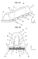
- FIG. 23 is a perspective view of an image reader according to Embodiment 4, and FIG. 22 is a cross-sectional view at the YZ plane (virtual plane) defined by the Y axis and the Z axis in the image reader 10 illustrated in FIG. 23 .
- the same or equivalent component is denoted by the same reference sign, and repeated explanation thereof is omitted.
- the image readers of Embodiments 1, 2 and 3 have the plurality of light-source elements 1 arrayed in the main scanning direction (X-axis direction) along the light shield member 5 so as to face the end portion of the transparent member 2 (light guide 2) opposite to the object-to-be-read M.
- This is called an array light-source type or a light-source array type (LED array type) since the light-source elements 1 are disposed in an array in the main scanning direction.
- the image reader of Embodiment 4 has the light-source elements 1 formed so as to face the end portion of the transparent member 2 (light guide 2) in the main scanning direction (X-axis direction).
- the optical axis of the light-source element 1 is substantially parallel to the X-axis direction.
- light emitted by the light-source element 1 travels efficiently through the transparent member 2 (light guide 2), reflects repeatedly in the interior of the transparent member 2 (light guide 2) and is guided in the main scanning direction (X-axis direction).
- This structure is called a side light type since the light-source elements 1 are disposed at the end portions of the transparent member 2 (light guide 2) in the main scanning direction (X-axis direction).
- the side light type image reader of Embodiment 4 employs a structure, i.e. the reflection area 15, to emit toward the object-to-be-read M light guided in the transparent member 2 (light guide 2), this structure being formed in the transparent member 2 (light guide 2).
- the reflection area 15 is formed at the end portion of the transparent member 2 (light guide 2) opposite to the object-to-be-read M along the main scanning direction (X-axis direction), and reflects light from the light-source elements 1 toward the object-to-be-read M. That is to say, the reflection area 15 can be said to be formed at the part of the light guide 2 corresponding to the location where light emitted by the light-source elements 1 of the image readers of Embodiments 1, 2 and 3 enters the light guide 2.
- the optical path that guides light reflected by the reflection area 15 toward the object-to-be-read-M side and guided in the light guide 2 corresponds to the optical path (i.e. first path 13a, second path 13b, second path 13c, second path 13d, second path 13e and second path 13f) for light emitted by the light-source elements 1 of the image readers of Embodiments 1, 2 and 3.
- the explanation for optical path that guides light reflected by the reflection area 15 toward the object-to-be-read-M side and guided in the light guide 2 is omitted.
- the above-explained reflection area 15 is formed on the side face of the light guide 2 along the main scanning direction (X-axis direction).
- the reflection area 15 may be a print (reflection pattern 15) on the side face of the light guide 2, or may be an irregularity (reflection prism 15) formed on the side face of the light guide 2.
- the reflection pattern 15 and the reflection prism 15 may change in width in the sub-scanning direction (Y-axis direction) in order to make light emitted to the object-to-be-read M uniform along the main scanning direction.
- the width in the sub-scanning direction can be zero. That is to say, the reflection pattern 15 and the reflection prism 15 may be non-continuous in the main scanning direction (X-axis direction).
- the reflection pattern 15 can be formed by applying a white paint in order to manufacture the reflection area 15.
- the reflection prisms 15 can be formed by embossing or by arranging micro structures. In these figures, the same or equivalent component is denoted by the same reference sign, and repeated explanation thereof is omitted.
- Embodiments 1, 2 and 3 the array light-source type that has the light-source elements 1 arrayed in the main scanning direction is employed, but in Embodiment 4, as illustrated in FIGS. 22 and 23 , a side light type is employed that has the light-source elements 1 disposed at both ends of the transparent member 2 in the main scanning direction (X-axis direction) or at one side in the main scanning direction (X-axis direction).
- the light-source elements 1 are also provided at the invisible side in the main scanning direction, that is, the light-source elements 1 are disposed at both ends of the transparent member 2 in the main scanning direction (X-axis direction).
- the number of light-source elements 1 facing both ends or one end of the transparent member 2 (light guide 2) in the main scanning direction (X-axis direction) is two for each end corresponding to the reflection area 15, but the number of the light-source elements 1 is not limited to this configuration.
- the reflection area 15 can be understood as an additional linear light source (array light source, light-source array). Therefore, the configurations of the image readers of Embodiments 1, 2 and 3 are also applicable to the image reader (side light type) of Embodiment 4.
- the reflection area 15 can be applied to the structures of the image reader of Embodiments 1, 2 and 3. That is to say, the imaging optical system 3 is disposed at a location out of the virtual plane through which pass the first virtual line passing through the array of intersection points of the optical axes of a plurality of lenses with the object-to-be-read M and parallel to the main scanning direction (X-axis direction), and the second virtual line passing through the reflection area 15 and parallel to the main scanning direction.
- the image reader according to Embodiment 4 which is the side light type, can reduce the number of light-source elements 1 disposed at the end portion of the transparent member 2 in the main scanning direction in comparison to the image readers of Embodiments 1, 2 and 3.
- the number of the mounted light-source elements 1 can be reduced, while at the same time, the present Embodiment has the advantageous effect of suppression of ripple, i.e. unevenness of the light intensity, which is a problem caused when the number of mounted light-source elements 1 is reduced in an array type light source.
- the light-source elements 1 can be disposed near the end portion of the transparent member 2 in the main scanning direction (X-axis direction) like the below-described light-source holder 31, and by use of a holder that has little leakage of light, a leakage to the external space of light emitted from the light-source elements 1 to the transparent member 2 can be suppressed.
- illumination efficiency can be improved in comparison with a configuration in which only the light-source elements 1 are arranged.
- the screw 9 corresponds to the engagement portion 2c explained using FIG. 9 .
- the image reader 10 is explained that has the light shield member 5 separate from a dust-proofing member 7.
- the structure of the image reader of Embodiment 5 is applicable to the structures of the image reader of Embodiments 1 to 4.
- an image reader 10 is explained that has the external side face of the transparent member 2 (light guide 2) formed in an arc shape.
- the arc-shaped external side face of the light guide portion 2a is also applicable to the image readers of Embodiments 1 to 4.
- FIG. 24 is a perspective view of the image reader according to Embodiment 5.
- FIG. 25 is a cross-sectional view of the image reader 10 at a virtual plane AA' that is a parallel plane to the YZ plane defined by the Y axis and the Z axis in FIG. 24 . More specifically, the virtual plane AA' is a cross-sectional view of a portion that intersects one of the multiple engagement portions 2c arrayed in the main scanning direction (X-axis direction).
- the virtual plane AA' is a cross section that intersects the two engagement portions 2c arranged side by side in the main scanning direction (X-axis direction).
- the virtual plane AA' can be said to be as a cross section that intersects one of the engagement portions 2c arrayed in the main scanning direction (X-axis direction).
- Embodiments of the present invention including this Embodiment 5, example configurations are explained in which the engagement portions 2c are arrayed in two rows sandwiching the imaging optical system 3 without arrangement in a zigzag pattern, and face one other in the sub-scanning direction (Y-axis direction).
- FIG. 26 is a cross-sectional view of the image reader 10 at a virtual plane BB' that is a parallel plane to the YZ plane defined by the Y axis and the Z axis in FIG. 24 .
- the virtual plane BB' is a cross section that intersects one of the light-source elements 1 disposed side by side in the main scanning direction (X-axis direction).
- the light-source elements 1 are arrayed in two rows across the imaging optical system 3 and are arranged in a zigzag pattern.
- the virtual plane BB' is a cross section that intersects one of the light-source elements 1 arrayed in the main scanning direction (X-axis direction).
- FIG. 27 is an illustrated parts breakdown (exploded oblique drawing) of the image reader illustrated in FIG. 24, FIG. 25 and FIG. 26 . As is clear from FIG. 27 , the light-source elements 1 arrayed in two rows are arranged in a zigzag pattern.
- the engagement portions 2c are fasteners that extend toward the board 6 from a flange 2i and that are formed at both sides of the end, opposite to the object-to-be-read M, of the transparent member 2.
- the flange 2i extends in the direction opposite to the imaging optical system 3.
- the fasteners can be said to be as portions for fastening together the board 6 and the flange 2i that extends from the end of the transparent member 2 opposite to the object-to-be-read M and in the direction opposite to the sensor IC 4.
- Embodiments 1 to 4 because the flange 2i is small, the flange is treated as a portion of the engagement portion 2c, but as in Embodiment 5, the flange can be a component that is separate from the engagement portions 2c. Structure strength is higher if the engagement portion 2c (fastener) and the flange 2i are integrated.
- the positioning hole 6b illustrated in FIG. 27 is explained together with the explanation of the image reader 10 illustrated in the below-described FIGS. 28 to 31 .
- the dust-proofing member 7 is arranged between the light shield member 5 and the board 6, and isolates from the exterior a through-hole portion 5a, which is a space surrounded by the light shield member 5, the surface of the imaging optical system 3 at the sensor-IC-4 side, and the board 6. More specifically, this is a member that suppresses entrance into the through-hole portion 5a of foreign materials from the portion of the board 6 at which the light-source elements 1 are arranged and foreign materials from the exterior of the image reader 10.
- the dust-proofing member 7 is arranged on the board in a rectangular shape so as to cover the periphery of the sensor IC 4.
- the dust-proof cover 7 is disposed in the main scanning direction (X-axis direction) so as to be divided into two pieces sandwiching the sensor IC 4.
- the dust-proofing member 7 is disposed in the sub-scanning direction (Y-axis direction) at outside of the photosensitive element disposed at the end portion in the main scanning direction (X-axis direction) with respect to the photosensitive element disposed next to the photosensitive element disposed at the end portion in the main scanning direction
- the dust-proofing member 7 has portions extending in the main scanning direction (X-axis direction) and in the sub-scanning direction (Y-axis direction), the portions connected with each other so as to form a rectangular shape.
- the board 6 of the image reader 10 has the sensor IC 4 fastened thereto by a means such as gluing.
- the dust-proofing member 7 formed of a rubber, a soft resin, or the like is fastened to the board 6 around the sensor IC 4, and the light shield member 5 (light shield 5), formed of a resin or a rigid material like metal, is mounted on the dust-proofing member 7.
- the light shield member 5 is formed with the through-hole portion 5a that has an opening that has a predetermined length in the sub-scanning direction, that passes through the light shield member in the direction (Z-axis direction) orthogonal to the main scanning direction and the sub-scanning direction, and that extends in the main scanning direction.
- a stepped portion, stepped in the Z-axis direction toward the board 6, is formed in the through-hole portion 5a.
- the stepped portion is shaped so as to increase in the width in the Y-axis direction toward the board 6 from a portion where the imaging optical system 3 is fitted in the through-hole portion 5a of the light shield member 5.
- the dust-proofing member 7 is arranged between the peripheral part of the through-hole portion 5a where Y-axis direction width is maximum and the board 6.
- the dust-proofing member 7, light shield member 5 and imaging optical system 3 are arranged in this manner on the board 6, thereby preventing foreign materials from entering to the sensor IC 4.
- the light shield member 5 and the imaging optical system 3 abutting the light shield member 5 are mounted on a portion of the board 6 where the dust-proofing member 7 is arranged.
- the engagement portions 2c of the transparent member 2 engaged with predetermined locations of the board 6, and thus the image reader 10 illustrated in FIG. 24 is obtained.
- FIG. 28 is a perspective view of the image reader according to Embodiment 5.
- FIG. 29 is a cross-sectional view of the image reader 10 at the virtual plane AA', which is a plane parallel to the YZ plane defined by the Y axis and Z axis illustrated in FIG. 28 .
- the virtual plane AA' is a cross-sectional view of a portion that intersects one of the multiple engagement portions 2c arrayed in the main scanning direction (X-axis direction). Note that the engagement portions 2c are arrayed in two rows sandwiching the imaging optical system 3.
- the virtual plane AA' is a cross section that intersects the two engagement portions 2c arrayed in the main scanning direction (X-axis direction).
- the virtual plane AA' can be said to be a cross section that intersects one of the engagement portions 2c multiply arrayed in the main scanning direction (X-axis direction).
- the engagement portions 2d are fasteners of the transparent member 2 that extend toward the board 6 from the flange 2i and are formed at both sides of the end, opposite to the object-to-be-read M, of the transparent member 2.
- the bosses 2e extend toward the board 6 from the flange 2i and are formed at the end of the transparent member 2 opposite to the object-to-be-read M.
- the bosses 2e can be formed at both sides of the end, opposite to the object-to-be-read M, of the transparent member 2.
- Holes 6a for engaging with the engagement portions 2d are formed respectively so as to pass through the board 6.
- Positioning holes 6b are used for positioning by insertion of the bosses 2e.
- the transparent member 2 employs a structure that has the internal recess 2L, and the dust-proofing member 7, light shield member 5 and imaging optical system 3 are retained in this recess 2L.
- the end of the imaging optical system 3 opposite to the sensor IC 4 is in contact with the bottom of the recess 2L of the transparent member 2 because the engagement portions 2d (fasteners) of the transparent member 2 hold the board 6 and the dust-proofing member 7 on the board 6 and the imaging optical system 3 supported by the light shield member 5 are pushed upwardly.
- the bosses 2e of the transparent member 2 are inserted in the positioning holes 6b of the board 6.
- the transparent member 2 is fastened to the board 6 by passing the engagement portions 2d through the holes 6a provided at the outer periphery of the board 6 so as to hold the board 6, and when the transparent member 2 is fastened to the board 6 in this manner, the dust-proofing member 7, light shield member 5 and imaging optical system 3 can be said to be pushed against so as to be fastened to the board 6. Moreover, in order to prevent mispositioning due to clearance between the hole 6a of the board 6 and the engagement portion 2d, the bosses 2e of the transparent member 2 are fitted in the positioning holes 6b of the board 6, thereby securing the aforementioned accurate positioning.
- the image reader 10 illustrated in FIG. 28 uses pressure of the transparent member 2 to fasten the dust-proofing member 7, light shield member 5 and imaging optical system 3 integrally to the board 6. Hence, the image reader 10 can be obtained using a simple structure.
- the image reader 10 illustrated in FIGS. 28 to 31 has portions of the board 6 that protrude in the Y-axis direction and at which the holes 6a are formed.
- the transparent member 2 further includes a portion that extends from the flange 2i toward the board 6 and is formed at both sides of the end portion opposite to the object-to-be-read M besides the engagement portions 2d of the transparent member 2.
- portions extending from the flange 2i toward the board 6 cover the side faces of the board 6.
- FIGS. 32 to 37 are cross-sectional views of a portion that intersects a fastener of the image reader 10 and one of the light-source elements 1 disposed arrayed in the main scanning direction (X-axis direction), and is a cross-sectional view (except for the fastener) at a location corresponding to the virtual plane BB' that is parallel to the YZ plane defined by the Y axis and the Z axis illustrated in FIG. 24 .
- the plurality of light-source elements 1 are arrayed in two rows along the main scanning direction (X-axis direction) sandwiching the imaging optical system 3 and are arranged in a zigzag pattern, and thus the virtual plane BB' is a cross section that intersects one of the light-source elements 1 arrayed in two rows.
- FIG. 32A illustrates a state in which a boss 2f (fastener) is fitted into the hole 6a.
- FIG. 32B illustrates a state in which the distal end of the boss 2f fitted in the hole 6a is thermally fusion bonded to the board 6.
- the bosses 2f are fasteners of the transparent member 2 that extend toward the board 6 from the flange 2i and that are formed at both sides of the end portion of the transparent member 2 opposite to the object-to-be-read M.
- the bosses 2f are fitted in the holes 6a, which pass through the board 6.
- the distal end of the boss 6f fitted in the hole 6a is thermally fusion bonded to the board, thereby fastening, with the transparent member 2 (bosses 2f), the opposite surface of the board 6 to the surface on which the sensor IC 4 is formed.
- the board 6 and the transparent member 2 are fastened by the engagement portions 2c or the engagement portions 2d of the transparent member 2.
- the bosses 2f are fitted in the holes 6a provided at the outer circumference of the board 6.
- a protrusion 2f of the boss 2f from the board 6 is melted by heat, thereby fastening the transparent member 2 to the board 6.
- the bosses 2f can be said to serve as parts for positioning, and after melted by heat, the bosses serve as a fastener.
- the bosses 2f correspond to the bosses 2e
- the holes 6a correspond to the positioning holes 6b.
- FIG. 33 the same or equivalent component is denoted by the same reference sign, and repeated explanation thereof is omitted.
- screws 9 are fitted in the holes 6a that pass through the board 6.
- the screws 9 are fitted in the holes 6a and screw holes 2j of the flange 2i, and are tightened.
- the screw holes 2j pass through the flange 2i from the object-to-be-read-M side to the board-6 side.
- FIGS. 34 and 35 the same or equivalent component is denoted by the same reference sign, and repeated explanation is omitted.
- clips 16 are fasteners that pinch the end portion of the flange 2i and that of the board 6 in the Y-axis direction, thereby fastening those components.
- Clips 17 are fasteners that clip both end portions of the flange 2i in the Y-axis direction from the surface of the board 6 opposite to the surface on which the sensor IC 4 is formed, thereby fastening those components.
- the clip 17 can be said to be such a clip that the two clips 16 are connected at the portions in the side of the surface opposite to surface on which the sensor IC 4 is formed.
- This portion of the clip 17 can be curved so as to abut against the board 6. More specifically, the apex of the curved portion of the clip 17 is made to press against the board 6.
- This curved portion has the same shape as that of the curved portion of the below-described elastic member 19.
- the flange 2i is provided at the outer periphery of the transparent member 2, and the flange 2i and the board 6 are pinched by the clips 16 (clips 17), thereby fastening together the transparent member 2 and the board 6.
- the fasteners (clips 16 and clips 17) can be separate components completely from the transparent member 2 and the board 6. Therefore, an image reader can be obtained that has a high degree of freedom of design, such as the selection of the locations where the fasteners (clips 16, clips 17) are provided and the number of fasteners (clip 16, clip 17).
- an adhesive 18 is used as a fastener that glues and fastens the flange 2i to the end portion of the board 6 in the Y-axis direction by adhesive, adhesive tape, or the like.
- the adhesive 18 may join the transparent member 2 to the board 6 across continuously the main scanning direction (X-axis direction), or may join the transparent member 2 with the board 6 intermittently in that direction.
- FIG. 37 the same or equivalent component is denoted by the same reference sign, and repeated explanation thereof is omitted.
- projections 2k are formed on the respective surfaces of the transparent member 2 located opposite to the retainer space 2L and at both of the front and back in the sub-scanning direction that intersects the main scanning direction.
- An elastic member 19 transparent-member fastening elastic member 19
- the projections 2k with respective through-holes are formed on the outer periphery of the transparent member 2, and the elastic member 19 is engaged with the through-holes of the projections 2k or the holes thereof, thereby fastening together the transparent member 2 and the board 6.
- the elastic member 19 has the first flat portion and the second flat portion that pass through the board 6 or hold the board 6 and exist between the surface of the board 6 on which the sensor IC 4 is formed and the opposite surface thereto, and has the curved portion pushed against the opposite surface of the board 6 to the surface on which the sensor IC 4 is formed and in contact with this surface.
- FIG. 37 An explanation is given of a configuration in which the structure of the image reader 10 illustrated in FIG. 37 is applied to the image reader of Embodiment 3, that is to say, the image reader 10 in a shape that exposes one of the two side faces of the imaging optical system 3 and light shield member 5 along the main scanning direction (X-axis direction) or one of the two side faces of the imaging optical system 3 along the main scanning direction (X-axis direction).
- the fasteners include first projections 2k formed on the surfaces of the transparent member 2 located opposite to the retainer space 2L (exactly same as the projections 2k formed on the transparent member 2 and illustrated in FIG. 37 ), and a second projection formed on a surface of the light shield member 5 opposite to the sensor IC 4 and exposed from the transparent member 2.
- the fasteners also include the elastic member 19, which is similar to the one illustrated in FIG. 37 . That is to say, the elastic member 19 includes the curved portion curved toward the other surface side of the board 6, and the first and the second flat portions formed at both ends of the curved portion, and to be engaged with the first projections 2k and the second projection respectively. Still further, the elastic member has first and second flat portions that pass through the board 6 or hold the board 6 and exist between the one surface of the board 6 and the other surface thereof, and has the curved portion pushed against the other surface of the board 6 and being in contact with this surface.
- the light shield member 5 may also be exposed together with the imaging optical system 3.
- the configurations may be grouped into two groups, one is a configuration in which the second projection is formed on the light shield member 5, and the other is a configuration in which the projection 2k is formed only on the transparent member 2.
- Embodiment 6 of the present invention is explained with reference to FIGS. 38 to 44 .
- the transparent member 2 (light guide 2) is made of transparent material, retains the imaging optical system 3 in the retainer space 2L, and fastens together a portion of the imaging optical system 3 at the object-to-be-read-M side and the retainer space 2L, or causes the imaging optical system 3 to be in contact partially with the retainer space 2L, thereby fastening the imaging optical system 3.
- the light shield member 5 supports the portion of the imaging optical system 3 at the sensor-IC-4 side, or is in contact with the portion of the imaging optical system 3 at the sensor-IC-4 side, blocks light other than light focused by the imaging optical system 3, and is covered by the transparent member 2.
- the image reader of Embodiment 6 and the image reader of other Embodiments are interchangeable with each other.
- FIGS. 38 to 44 are each a cross-sectional view of the fasteners (engagement portions 2c) of the image reader 10 and a portion that intersects one of the plurality of light-source elements 1 arrayed in the main scanning direction (X-axis direction), and is a cross-sectional view at a location corresponding to the virtual plane BB' that is a plane parallel to the YZ plane defined by the Y axis and the Z axis in FIG. 24 (except for the fasteners (engagement portions 2c)).
- the plurality of light-source elements 1 are arrayed in two rows along the main scanning direction (X-axis direction) sandwiching the imaging optical system 3 and are arranged in a zigzag pattern, and thus the virtual plane BB' is a cross section that intersects one of the light-source elements 1 disposed in two rows.
- the light shield member 5 and the board 6 are not illustrated.
- the transparent member 2 illustrated in FIG. 42, FIG. 43 and FIG. 44 are in a state prior to fastening (engaging) of the board 6.
- the imaging optical system 3 when the object-to-be-read-M side of the imaging optical system 3 is fastened to the retainer space 2L by the light shield member 5 in addition to a support by fitting the imaging optical system 3 in the through-hole portion 5a, the imaging optical system 3 can be only in contact with the through-hole portion 5a or the light shield member 5.
- an image reader 10 can be obtained that can hold the imaging optical system 3 regardless of the magnitude of holding force of the board 6 by the fasteners (engagement portions 2c and the like).
- the imaging optical system 3 In the fastening of the imaging optical system 3, rather than just supporting by fitting the imaging optical system 3 in the through-hole portion 5a, when the object-to-be-read-M side of the imaging optical system 3 is fastened to the retainer space 2L by the light shield member 5, the imaging optical system 3 can be only in contact with the through-hole portion 5a or the light shield member 5.
- the transparent member 2 employs a structure that has the recess 2L in the interior, and the light shield member 5 and the imaging optical system 3 are retained in this recess 2L.
- the end portion of the imaging optical system 3 opposite to the sensor IC 4 is in contact with the bottom of the recess 2L of the transparent member 2.
- an image reader can be obtained that can hold the imaging optical system 3 regardless of the magnitude of holding force of the board 6 by the fastener (for example, engagement portion 2c).
- the light shield member 5 (elastic member) is deformable, and when depressed, the portion in contact with the board 6 deforms slightly, thereby also accomplishing the function of the dust-proofing member 7.
- the transparent member 2 may have the engagement portions 2c catching the outer circumference of the board 6, thereby being fastened with the board 6, and when the transparent member 2 is fastened to the board 6 in this manner, the light shield member 5 and the imaging optical system 3 may be fastened by being pressed against the board 6.
- the light shield member 5 (elastic member) and the dust-proofing member 7 can be separate components.
- an adhesive 21 can be used that is non-transparent, such as a colored adhesive having a light shielding function. This is similar to the configuration, explained in Embodiment 1, in which the transparent resin 2r (adhesive 21) is not transparent.
- the virtual plane is a cross-sectional view of a portion that intersects one of the multiple engagement portions 2c arrayed in the main scanning direction (X-axis direction). Since the engagement portions 2c are arrayed in two rows along the main scanning direction (X-axis direction) sandwiching the imaging optical system 3, in a precise sense, the virtual plane is a cross section that intersects the two engagement portions 2c disposed in two rows.
- the same or equivalent component is denoted by the same reference sign, and repeated explanation is omitted.
- the light-source elements 1 are arranged on the same surface of the board 6 on which the sensor IC 4 is formed and at end portions in the main scanning direction (X-axis direction).
- the light-source elements 1 are formed at both ends in the main scanning direction (X-axis direction), but can be formed at only one end.
- the transparent member 2 has the end portions curved toward the board 6 along the main scanning direction (X-axis direction), and covers the light-source elements 1.
- the path (optical path) for light reflected in the Z-axis direction is the same as that of light emitted from the light-source elements 1 in other Embodiments.
- the method of fastening the dust-proofing member 7, light shield member 5, imaging optical system 3 and transparent member 2 to the board 6 of the image reader 10 in FIG. 47 is the same as in the other Embodiments.
- the image reader 10 illustrated in FIGS. 45 , 46 and 47 is a side light type, an image reader having the light-source elements 1 formed on the board 6 or on the XY plane can be obtained.
- each light-source holder 31 (LED holders 31) each allow the end portion of the transparent member 2 to be fitted in a surface on which the light-source elements 1 are mounted. As illustrated in FIG. 49 , each light-source holder 31 is formed with a recess that retains therein a board on which the light-source elements 1 are formed, and the end portion of the transparent member 2.
- the holder pins 31a fit in the holder-pin holes 2m and the holder-pin holes 6c, and the light-source holder 31 thereby fastens to the end portion of the transparent member 2 in the main scanning direction (X-axis direction). More specifically, the barb of the snap fit tip of the holder pin 31a protrudes from the surface of the board 6 opposite to the surface on which the sensor IC 4 is formed, and thus the light-source holder 31 is fastened.
- the portion of the board 6 in which the holder-pin hole 6c is formed can be exposed when the flange 2i is not formed at the end portion of the transparent member 2 in the main scanning direction (X-axis direction), and the holder pin 31a can be fitted directly in such a holder-pin hole 6c.
- the holder pin 31a can be inserted into only the holder pin holes 2m formed in the flange 2i.
- the holder-pin hole 6c may not be formed, and the holder pin 31a can be inserted into only the holder-pin holes 2m formed in the flange 2i.
- the reflection area 15 that reflects light from the light-source elements 1 is formed at the end portion of the transparent member 2 at the opposite side to the object-to-be-read M along the main scanning direction (X-axis direction), and the light-source holder 31 is fixed to the flange 2 of the transparent member 2 (board 6) outside of the photosensitive element disposed at the end portion in the main scanning direction (X-axis direction) with respect to the photosensitive element disposed next to the photosensitive element disposed at the end portion of the sensor IC 4 in the main scanning direction (X-axis direction).
- FIGS. 48 , 49 and 50 is a side light type
- an image reader can be obtained that has built-in light-source elements 1.
- the cross-sectional view of FIG. 50 shows the same shape as that of the cross-sectional view of FIG. 47 , because the layout of the light-source elements 1 is the only difference these image readers.
Landscapes
- Engineering & Computer Science (AREA)
- Multimedia (AREA)
- Signal Processing (AREA)
- Physics & Mathematics (AREA)
- General Physics & Mathematics (AREA)
- Facsimile Heads (AREA)
- Facsimile Scanning Arrangements (AREA)
- Light Sources And Details Of Projection-Printing Devices (AREA)
- Image Input (AREA)
Abstract
Description
- The present invention relates to an image reader that reads the image of an object-to-be-read.
- Conventionally, image readers are used in facsimile machines, copying machines, scanners, banknote checking devices, inspection devices, fingerprint verifying devices and the like. Image readers are used to read various types of object-to-be-reads such as manuscripts, books, pages of a magazines, documents, paintings, photographs, transparent positives, rolls of film, banknotes, securities, circuit boards, electronic components and fingerprints. In addition, image readers receive reflected light from the object-to-be-read through sensor elements, i.e. photosensitive elements, thereby obtaining the image of the object-to-be-read.
- The reflected light from the object-to-be-read includes not only visible light but also light with wavelengths other than those of the visible light. Hence, the types of the light source incorporated in the image reader or provided external to the image reader, i.e. the light source used for emission of light to illuminate the object-to-be-read and to obtain reflected light, include not only types that emit visible light but also types that emit light of non-visible wavelengths.
- If the light source is incorporated in the image reader, light is emitted from light-source elements (point light sources) such as LEDs or organic EL elements, the emitted light is guided through the interior of a light guide (light guiding member) formed of a transparent material (transparent member) such as a resin, and the guided light is emitted to illuminate the object-to-be-read (see, for example,
Patent Literatures 1 to 7). - Needless to say, there are also light sources that have no light guide. Regardless of the presence/absence of the light guide in the light source, there are also image readers that have no built-in light source (see, for example, Patent Literature 8) and that can use such a light source.
-
Patent Literatures Patent Literatures Patent Literatures Patent Literature 7 discloses an image reader that includes a board having imaging elements disposed on a light guide. -
- Patent Literature 1:
- Unexamined Japanese Patent Application Kokai Publication
JP H11-266 340 A FIG. 2 ,FIG. 9 , andFIG. 10 ) - Patent Literature 2:
- National Patent Publication No. 2002-527832 (see, in particular,
FIGS. 3 and 4 ) - Patent Literature 3:
- Unexamined Japanese Patent Application Kokai Publication
JP H10-126 579 A FIG. 3 ) - Patent Literature 4:
- Unexamined Japanese Patent Application Kokai Publication
JP H10-210 216 A FIG. 14 ) - Patent Literature 5:
- Unexamined Japanese Patent Application Kokai Publication
JP H10-243 166 A FIG. 3 ) - Patent Literature 6:
- Unexamined Japanese Patent Application Kokai Publication
JP 2006-285 659 A FIG. 3 ) - Patent Literature 7:
- Unexamined Japanese Patent Application Kokai Publication
JP H9-247 360 A FIG. 1 ) - Patent Literature 8:
- Unexamined Japanese Patent Application Kokai Publication
JP H6-305 191 A FIG. 1 ) - However, conventional image readers have the following technical problems. The image readers disclosed in
Patent Literatures 1 to 5, and 7 have problems in that structural complexity and large size are difficult to be avoided. Although the light guide and the lens (imaging optical system) are configured in contact with each other in the image readers disclosed inPatent Literatures Patent Literature 6 has a simple configuration, this literature does not disclose the details of the lens (imaging optical system), and thus the degree of accuracy of the obtained image is still left as a technical problem. Still further, the image reader disclosed inPatent Literature 8 ignores matters other than the positioning of the lens (imaging optical system) with respect to the photosensitive elements, and this literature does not disclose the details of the light source. - The object of the present invention is to obtain an image reader that can perform highly accurate reading and has simple structure, without increase in complexity or size of the structure.
- According to the present invention, an image reader is provided that is configured to focus light emitted from a light source and reflected by an object-to-be-read, and to read an image of the object-to-be-read, the image reader including:
- a board;
- a line sensor assembly including a plurality of photosensitive elements formed on one surface of the board along a main scanning direction;
- a lens array assembly including a plurality of lenses arrayed along the main scanning direction, and configured to focus the reflected light onto the line sensor assembly;
- a light shield configured to support or to be in contact with a portion of the lens array assembly at the line-sensor-assembly side, and to block light other than the light focused by the lens array assembly;
- a transparent member made of transparent material retaining the lens array assembly and the light shield in a retainer space, and covering a portion of the lens array assembly at the object-to-be-read side and the light shield.
- According to the image reader of the present invention, the imaging optical elements (lens array and photosensitive elements) are reliably supported, and this has the advantageous effect of not requiring a casing that supports directly the imaging optical elements (lens array and photosensitive elements).
-
-
FIG. 1 is a perspective view of an image reader according toEmbodiment 1 of the present invention; -
FIGS. 2A to 2E are cross-sectional views of the image reader according toEmbodiment 1 of the present invention; -
FIG. 3 is a cross-sectional view of the image reader according toEmbodiment 1 of the present invention; -
FIG. 4 is a cross-sectional view of the image reader according toEmbodiment 1 of the present invention; -
FIG. 5 is an illustrated parts breakdown (exploded perspective view) of the image reader according toEmbodiment 1 of the present invention; -
FIG. 6 is a cross-sectional view of the image reader according toEmbodiment 1 of the present invention; -
FIG. 7 is a perspective view of the image reader according toEmbodiment 1 of the present invention; -
FIG. 8 is a cross-sectional view of the image reader according toEmbodiment 1 of the present invention; -
FIG. 9 is a cross-sectional view of the image reader according toEmbodiment 1 of the present invention; -
FIGS. 10A to 10C illustrate a functional block diagram and graphs of the image reader according toEmbodiment 1 of the present invention; -
FIG. 11 is a cross-sectional view of the image reader according toEmbodiment 1 of the present invention; -
FIG. 12 is a cross-sectional view of an image reader according toEmbodiment 2 of the present invention; -
FIG. 13 is a cross-sectional view of the image reader according toEmbodiment 2 of the present invention; -
FIG. 14 is a cross-sectional view of an image reader according toEmbodiment 3 of the present invention; -
FIGS. 15A and 15B illustrate a cross-sectional view and a perspective view of the image reader according toEmbodiment 3 of the present invention; -
FIG. 16 is a cross-sectional view of the image reader according toEmbodiment 3 of the present invention; -
FIGS. 17A and 17B illustrate a cross-sectional view and a perspective view of the image reader according toEmbodiment 3 of the present invention; -
FIG. 18 is a cross-sectional view of the image reader according toEmbodiment 3 of the present invention; -
FIGS. 19A and 19B illustrate a cross-sectional view and a perspective view of the image reader according toEmbodiment 3 of the present invention; -
FIG. 20 is a cross-sectional view of the image reader according toEmbodiment 3 of the present invention; -
FIGS. 21A and 21B illustrate a cross-sectional view and a perspective view of the image reader according toEmbodiment 3 of the present invention; -
FIG. 22 is a cross-sectional view of an image reader according toEmbodiment 4 of the present invention; -
FIG. 23 is a perspective view of the image reader according toEmbodiment 4 of the present invention; -
FIG. 24 is a perspective view of an image reader according toEmbodiment 5 of the present invention; -
FIG. 25 is a cross-sectional view of the image reader according toEmbodiment 5 of the present invention; -
FIG. 26 is a cross-sectional view of the image reader according toEmbodiment 5 of the present invention; -
FIG. 27 is an illustrated parts breakdown (exploded oblique drawing) of the image reader according toEmbodiment 5 of the present invention; -
FIG. 28 is a perspective view of the image reader according toEmbodiment 5 of the present invention; -
FIG. 29 is a cross-sectional view of the image reader according toEmbodiment 5 of the present invention; -
FIG. 30 is a cross-sectional view of the image reader according toEmbodiment 5 of the present invention; -
FIG. 31 is an illustrated parts breakdown (exploded oblique drawing) of the image reader according toEmbodiment 5 of the present invention; -
FIGS. 32A and 32B are a cross-sectional view of the image reader according toEmbodiment 5 of the present invention; -
FIG. 33 is a cross-sectional view of the image reader according toEmbodiment 5 of the present invention; -
FIG. 34 is a cross-sectional view of the image reader according toEmbodiment 5 of the present invention; -
FIG. 35 is a cross-sectional view of the image reader according toEmbodiment 5 of the present invention; -
FIG. 36 is a cross-sectional view of the image reader according toEmbodiment 5 of the present invention; -
FIG. 37 is a cross-sectional view of the image reader according toEmbodiment 5 of the present invention; -
FIG. 38 is a cross-sectional view of an image reader according toEmbodiment 6 of the present invention; -
FIG. 39 is a cross-sectional view of the image reader according toEmbodiment 6 of the present invention; -
FIG. 40 is a cross-sectional view of the image reader according toEmbodiment 6 of the present invention; -
FIG. 41 is a cross-sectional view of the image reader according toEmbodiment 6 of the present invention; -
FIG. 42 is a cross-sectional view of the image reader according toEmbodiment 6 of the present invention; -
FIG. 43 is a cross-sectional view of the image reader according toEmbodiment 6 of the present invention; -
FIG. 44 is a cross-sectional view of the image reader according toEmbodiment 6 of the present invention; -
FIG. 45 is a perspective view of an image reader according toEmbodiment 7 of the present invention; -
FIG. 46 is an illustrated parts breakdown (exploded oblique drawing) of the image reader according toEmbodiment 7 of the present invention; -
FIG. 47 is a cross-sectional view of the image reader according toEmbodiment 7 of the present invention; -
FIG. 48 is a perspective view of the image reader according toEmbodiment 7 of the present invention; -
FIG. 49 is an illustrated parts breakdown (exploded oblique drawing) of the image reader according toEmbodiment 7 of the present invention; and -
FIG. 50 is a cross-sectional view of the image reader according toEmbodiment 7 of the present invention. - An image reader according to the present invention is an image reader that focuses reflected light that is light (illumination light) emitted from a light source (light-source elements 1) and reflected by an object-to-be-read M to read the image thereof, and that includes a
board 6, aline sensor assembly 4 that has a plurality of photosensitive elements formed on one surface of theboard 6 along the main scanning direction, a lens array assembly 3 (imaging optical system 3) having a plurality of lenses arrayed along the main scanning direction, and focusing the reflected light on theline sensor assembly 4, alight shield 5 supporting a portion of thelens array assembly 3 at the line-sensor-assembly-4 side, or being in contact with the portion of thelens array assembly 3 at the line-sensor-assembly-4 side, and blocking light other than the light focused by thelens array assembly 3, and atransparent member 2 made of transparent material retaining thelens array assembly 3 and thelight shield 5 in a retainer space, and covering a portion of thelens array assembly 3 at the object-to-be-read-M side and thelight shield 5. - Embodiments of the present
invention including Embodiment 1 are explained below. In the explanation for the respective Embodiments and the explanation for the respective figures, the same or equivalent components are denoted by the same reference signs. The following explanation is given of an "image reader 10" that is an example image reader of the present invention. -
Embodiment 1 of the present invention is explained with reference toFIGS. 1 to 11 .FIG. 1 is a perspective view of the image reader ofEmbodiment 1. Theimage reader 10 is a contact image sensor (CIS). The X-axis direction illustrated inFIG. 1 indicates the main scanning direction of theimage reader 10. The Y-axis direction indicates the sub-scanning direction intersecting (at right angle) with the main scanning direction of theimage reader 10. - The sub-scanning direction is a feeding direction in which the object-to-be-read M is fed. The Z-axis direction is an axial direction orthogonal to an XY plane defined by the X axis and the Y axis, is also an optical axis direction of the imaging
optical system 3 of theimage reader 10, and is a reading depth direction that is a direction to indicate the focal depth of the imagingoptical system 3. -
FIG. 2A is a cross-sectional view of theimage reader 10 at a virtual plane AA' that is a parallel plane with an YZ plane defined by the Y axis and the Z axis illustrated inFIG. 1 . More specifically, the virtual plane AA' is a cross-section of a portion that intersects one of the plurality of light-source elements 1 arrayed in the main scanning direction (X-axis direction). Note that the plurality of light-source elements 1 are arrayed in two rows along the main scanning direction (X-axis direction) side-by-side rows sandwiching the imagingoptical system 3 therebetween. - Hence, in a precise sense, the virtual plane AA' is a cross section that intersects two of the light-
source elements 1 disposed respectively in the two rows. Needless to say, when the light-source elements 1 disposed side by side in respective two rows along the main scanning direction (X-axis direction) across the imagingoptical system 3 are arranged in a zigzag pattern, the virtual plane AA' is a cross section that intersects one of the plurality of light-source elements 1. -
Embodiments Embodiment 1 are explained for an example configuration in which the light-source elements 1 disposed side by side in the two rows across the imagingoptical system 3 are not arranged in the zigzag pattern, but face one another in the sub-scanning direction (Y-axis direction). The object-to-be-read M is a reading-target medium (illuminated object) with image information, such as manuscripts, books, magazine pages, documents (general documents), paintings, photographs, transparent positives, rolls of film, banknotes, securities, circuit boards, electronic components and fingerprints. -
FIGS. 2B, 2C and 2D illustrate configurations in which a space (hereinafter, referred to as a "space S") is present between the imagingoptical system 3 and thetransparent member 2 in theimage reader 10 illustrated inFIG. 2A . Whentransparent resin 2r is present in the space S as illustrated inFIGS. 2C and 2D , theimage reader 10 is also presumed to have the space S.FIG. 2E illustrates a configuration in which thetransparent member 2 of theimage reader 10 inFIG. 2A is formed with a below-described cut-out 2n (cut-outportion 2n). The cut-out 2n (cut-outportion 2n) exposes the imagingoptical system 3 to the object-to-be-read M. In theimage reader 10 illustrated inFIG. 2E , the space S can be said to be opened. - In
FIGS. 1 and2 , thetransparent member 2 is a light guide member that is formed, for example, of resin or glass, and that extends in the X-axis direction. Hence, the transparent member can be also referred to as a light guide. When, in particular, light (illumination light) emitted by the light-source elements 1 that are the light source for theimage reader 10 is guided through the interior of thetransparent member 2, thetransparent member 2 is referred to as alight guide 2. In Embodiment of the present invention, an example configuration is explained in which theimage reader 10 includes the light-source elements 1 (light source). InEmbodiment 1, the previously explained plurality of light-source elements 1 face an end portion of thetransparent member 2 opposite to the object-to-be-read M, and are arrayed in the main scanning direction (X-axis) along the light shield member 5 (light shield 5), thus serving as a light source. - As explained above, Embodiment of the present invention discloses only a structure in which the
transparent member 2 is thelight guide 2, but the present invention is applicable to a configuration in which the light-source elements 1 exist outside theimage reader 10, and light from the light-source elements 1 does not enter the interior of thetransparent member 2, but rather illuminates directly the object-to-be-read M. - In any configuration, except the configuration in which the optical path (path of propagation of light, including reflected light) of the reflected light from the object-to-be-read M is cut out (that is, the cut-
out 2n is formed) between the imagingoptical system 3 and the object-to-be-read M, the reflected light from the object-to-be-read M passes through the interior of thetransparent member 2. That is to say, in a configuration in which thetransparent member 2 functions by guiding the light from the light source (light-source elements 1) through the interior of thetransparent member 2, and by emitting the guided light to the object-to-be-read M, the transparent member can be called "light guide 2". - When the
transparent member 2 is configured as thelight guide 2 in this way, the optical path for light from the light source (light-source elements 1) includes a portion formed as the optical path of reflected light of thelight guide 2. Note that a point light-source element, such as an LED (Light Emitting Diode) or an organic EL (Organic Electro Luminescence), is suitable for the light-source element 1 (light source), but the present invention is not limited to the point light source. In Embodiments of the present invention, the explanation is given of an example configuration in which the light-source element 1 is an LED. - In
FIGS. 1 and2 , alight guide portion 2a of thelight guide 2 indicates a part where light from the light source (light-source elements 1) is guided in thelight guide 2. An object-to-be-readfeeding side face 2b of the light guide 2 (transparent member 2) is, among the surfaces of the light guide 2 (transparent member 2), a surface facing the fed object-to-be-read M. On the object-to-be-read-feeding-side-face-2b side and at the opposite side to the imagingoptical system 3, it is provided a reading position of the imagingoptical system 3, which is the focal point thereof. - When the focal point is arranged on the object-to-be-read
feeding side face 2b, in order to read the object-to-be-read M, the fed object-to-be-read M passes on or in close vicinity of the object-to-be-readfeeding side face 2b. Hence, the object-to-be-readfeeding side face 2b can be understood as adocument placement surface 2b. In Embodiments of the present invention, an example configuration is explained in which such an object-to-be-readfeeding side face 2b can be understood as thedocument placement surface 2b. In addition, when the light guide 2 (transparent member 2) is provided with a cut-out 2n as explained above, the object-to-be-readfeeding side face 2b (document placing surface 2b) is completely or partially omitted. - In this configuration, at least a part of the object-to-be-read
feeding side face 2b (document placing surface 2b) is a virtual surface. Needless to say, the object-to-be-read M is not in contact with the virtual surface. The details of the configuration in which the cut-out 2n is formed are explained later. - In
FIGS. 1 and2 the imagingoptical system 3 is thelens array assembly 3 which has a plurality of lenses arrayed along the main scanning direction, and which focuses light toward the line sensor assembly. In Embodiments of the present invention, although the explanation is given of an example configuration in which the imaging optical system 3 (lens array assembly 3) is constructed by having a plurality of rod lenses (rod lens array) disposed side by side in an array and held between plates, other lens arrays, such as a micro lens array that is the same erecting equal-magnification type optical system as the rod lens array, are applicable. If the micro lens array is used, the imagingoptical system 3 becomes a microlens array assembly 3 that has a plurality of lenses (lens array) held between plates. - If the imaging
optical system 3 is configured as an erecting equal-magnification type optical system, the object-to-be-readfeeding side face 2b may have a lens function. This lens function can be accomplished by, for example, cutting out a part of thetransparent member 2 corresponding to the optical path (a path through which light (including reflected light) travels) of reflected light from the object-to-be-read M and located between the imagingoptical system 3 and the object-to-be-read M, and fitting a lens in this cut-out 2n. In such configurations, a lens is formed by the object-to-be-readfeeding side face 2b, and another lens is fastened to aretainer space 2L of thetransparent member 2 in which the imagingoptical system 3 is retained. The imagingoptical system 3 is not limited to the erecting equal-magnification type optical system as long as such a system can be retained in theretainer space 2L of thetransparent member 2 or can be formed on thetransparent member 2, including the object-to-be-readfeeding side face 2b. - In addition, the imaging
optical system 3 is provided between thetransparent member 2 and theboard 6, and in thisEmbodiment 1, the imagingoptical system 3 is fastened to thelight shield member 5 arranged between the imagingoptical system 3 and theboard 6, but may be held on thetransparent member 2 by adhesive 21 (adhesive 22), tape and the like, and awedge member 23 may be pressed in between thetransparent member 2 and the imagingoptical system 3 to fasten the imaging optical system. Such a configuration is explained inEmbodiment 6, which is explained below together with the explanation of the adhesive 21 (adhesive 22). - The optical axis of the imaging
optical system 3 is disposed so as to be perpendicular to the reading surface (document surface) of the object-to-be-read M, and the imagingoptical system 3 has a function of forming an image on asensor IC 4 that is a light receiver assembly for focusing reflected light from the object-to-be-read M. Thesensor IC 4 is the line sensor assembly 4 (can be referred to as a sensor array assembly 4) that has a plurality of photosensitive elements formed along the main scanning direction on one surface of theboard 6. Thesensor IC 4 receives light focused by the imagingoptical system 3, performs photoelectric conversion, and outputs electric signals. On thesensor IC 4 is mounted a light receiver assembly composed of a semiconductor chip, other drive circuits and the like. These mounted components are arranged on the one surface of theboard 6, the other surface thereof and in the interior thereof. - The
light shield member 5 supports a portion of the imagingoptical system 3 at the sensor-IC-4 side, and functions as alight shield 5 that blocks light other than light focused by the imagingoptical system 3. Thelight shield member 5 disposed between theboard 6 and the imagingoptical system 3 is provided with a structure having an opening having a certain length in the sub-scanning direction at least a length so as to surround the photosensitive elements of thesensor IC 4, and penetrating in the direction orthogonal to the main scanning direction and the sub-scanning direction, that is, penetrating in the optical axis direction (Z-axis direction) and extending in the main scanning direction. Thelight shield member 5 has a function of blocking light entering to thesensor IC 4 from the exterior of the above-describedimage reader 10. - The
light shield member 5 is preferably formed of a black resin having a low reflectivity or an anodized material so that light passing through the imagingoptical system 3 but not entering to thesensor IC 4 and scattered and reflected by theboard 6 and further reflected by the surrounding components does not enter thesensor IC 4. In addition, thelight shield member 5 has a dust-proofing effect in that foreign materials are prevented from entering to thesensor IC 4. In other Embodiments, the dust-proofing effect of thelight shield member 5 is explained for configurations using another component (dust-proofing member 7). - In addition, as illustrated in
FIGS. 3 and 4 , the light-source elements 1 may be covered by thetransparent member 2 to accomplish the dust-proofing effect.FIGS. 3 and 4 are cross-sectional views of theimage reader 10 at the YZ plane (virtual plane) defined by the Y axis and the Z axis as inFIGS. 2A to 2E , and are each a cross-sectional view of a part where the light-source elements 1 are disposed. First, according to theimage reader 10 illustrated inFIG. 3 , end portions of thetransparent member 2, which are surfaces arranged opposite to the retainer space that retains the imagingoptical system 3 and that are located at the opposite side to the object-to-be-read M, protrude and are in contact with theboard 6 along the main scanning direction at both of the front and the back in the sub-scanning direction. - According to this structure, the protruding portions of the
transparent member 2 illustrated inFIG. 3 can accomplish the dust-proofing function. Hence, thesensor IC 4 can be protected from dust even if the dust-proofing function of thelight shield member 5 alone is deficient. In addition, since the protruding portions of thetransparent member 2 have the dust-proofing function, the light-source elements 1 are also protected from dust. Next, according to theimage reader 10 illustrated inFIG. 4 , the end portions of thetransparent member 2 opposite to the object-to-be-read M extend between the plurality of light-source elements 1 (light source array) disposed as an array and thelight shield member 5, and are in contact with theboard 6 along the main scanning direction. - According to this structure, the extended portions of the
transparent member 2 illustrated inFIG. 4 can accomplish the dust-proofing function. Hence, thesensor IC 4 can be protected from dust even if the dust-proofing function of thelight shield member 5 alone is deficient. Needless to say, a combination of the protruding portions of thetransparent member 2 illustrated inFIG. 3 and inFIG. 4 may be employed. - Electronic components, such as the light-
source elements 1, thesensor IC 4, anexternal connector 8 and a signal processor IC 11 such as an IC using an ASIC (Application Specific Integrated Circuit) are mounted on theboard 6. In conjunction with a CPU (Central Processing Unit) 12a and RAM (Random Access Memory) 12b, the signal processor IC 11 performs signal processing on, for example, the photoelectric conversion output received through thesensor IC 4. TheCPU 12a, theRAM 12b and asignal processing circuit 12c in the signal processor IC 11 are collectively referred to as asignal processor 12. Theexternal connector 8 is utilized as an input/output signal interface for the photoelectric conversion output by thesensor IC 4, and other signal processing outputs. -
FIG. 5 is an illustrated parts breakdown (exploded oblique drawing) of the image reader according toEmbodiment 1. The image reader according to Embodiment of the present invention includes thetransparent member 2, the imagingoptical system 3 and thesensor IC 4, which have lengths equal to or greater than the effective reading width of the object-to-be-read M (effective reading width in main scanning direction). InFIG. 5 , the reference sign of the light-source elements 1 is indicated only for the light-source elements (in the figure, four elements) disposed at the ends in the main scanning direction (X-axis direction) of the light source, and such indication is omitted for the other elements. - According to the
image reader 10 shown inFIG. 1 to FIG. 5 , thetransparent member 2 retains the imagingoptical system 3 and thelight shield member 5 in the retainer space, and covers a part of the imagingoptical system 3 at the object-to-be-read-M side and thelight shield member 5. In addition, the explanation is given of an example case in which fasteners of theimage reader 10 of the present invention (engagement portion 2c,engagement portion 2d,boss 2e, screw 9,clip 16,clip 17, adhesive 18, and elastic member 19) fasten thetransparent member 2 to theboard 6, and the pressing force from theboard 6 by this fastening causes thelight shield member 5 and the imagingoptical system 3 to be in contact with thetransparent member 2. - However, the fasteners of the
image reader 10 of the present invention (engagement portion 2c,engagement portion 2d,boss 2e,boss 2f andengagement portion 2g) can fasten thetransparent member 2 to theboard 6, and the pressing force from theboard 6 by this fastening can bring thelight shield member 5 into contact with thetransparent member 2. Likewise, thetransparent member 2 can be fastened to theboard 6, and the pressing force from theboard 6 by this fastening can cause the imagingoptical system 3 to be in contact with thetransparent member 2 via thelight shield member 5. The illustration of theimage reader 10 in such a configuration is omitted. - The
engagement portion 2c is explained later with reference toFIGS. 6 to 9 . Theengagement portion 2d,boss 2e, screw 9,clip 16,clip 17, adhesive 18, and theelastic member 19 are explained inEmbodiment 5. In addition, in the image reader of the present invention, the fastener may be understood as a fastener that further includes a part of thetransparent member 2 or theboard 6 related to the fastening of thetransparent member 2 with theboard 6 by theengagement portion 2c,engagement portion 2d,boss 2e, screw 9,clip 16,clip 17, adhesive 18 andelastic member 19. - When the
transparent member 2 is fastened to theboard 6 by the fastener (engagement portion 2c,engagement portion 2d,boss 2e,boss 2f andengagement portion 2g), and the pressing force from theboard 6 by this fastening causes thelight shield member 5 to be in contact with thetransparent member 2, or when, by the fastener (engagement portion 2c,engagement portion 2d,boss 2e,boss 2f andengagement portion 2g), the imagingoptical system 3 is brought into contact with thetransparent member 2 but the imagingoptical system 3 is not in contact with thetransparent member 2 at the tip of the imagingoptical system 3 at the object-to-be-read-M side, that is, at a portion facing a part of thetransparent member 2 through which reflected light from the object-to-be-read M passes, as illustrated inFIG. 2B , the space S can be formed between the portion of thetransparent member 2 through which reflected light from the object-to-be-read M passes and a portion of the imagingoptical system 3 facing that portion (tip of imagingoptical system 3 at object-to-be-read-M side). - When the space S is formed, Fresnel reflection can be caused when reflected light from the object-to-be-read M travels to the space S from the
transparent member 2. If such reflection occurs, Fresnel reflection can be suppressed if the space S is filled as in theimage reader 10 illustrated inFIG. 2C with atransparent resin 2r, i.e. a resin having transparency (suitably having the same or similar refraction index as that of the transparent member 2). For to theimage readers 10 illustrated inFIGS. 2B and 2C , like theimage reader 10 illustrated inFIG. 2A , the same condition is illustrated as in the configuration in which the end portion of the imagingoptical system 3 at the object-to-be-read-M side is in contact with thetransparent member 2. - That is to say, according to the
image reader 10 illustrated inFIGS. 2B and 2C , in order to fasten the imagingoptical system 3 to thetransparent member 2, only the plate that supports the plurality of lenses in the imagingoptical system 3, or the plate and a portion of the imagingoptical system 3 that is not optically functional, is in contact with thetransparent member 2. - Needless to say, when the space S is filled beforehand with the
transparent resin 2r, like theimage reader 10 illustrated inFIG. 2D , it is unnecessary to cause thetransparent member 2 to be contacted with only the plate supporting the plurality of lenses in the imagingoptical system 3 or the plate and the portion of the imagingoptical system 3 that is not optically functional. Theexample image reader 10 according toEmbodiment 6 illustrates a configuration in which the adhesive 21 is applied as thetransparent resin 2r to fasten the imagingoptical system 3 to thetransparent member 2. - In addition, like the
image reader 10 illustrated inFIG. 2D , thetransparent member 2 can be brought into contact with only the plate supporting the plurality of lenses in the imagingoptical system 3 or the plate and the portion of the imagingoptical system 3 that is not optically functional, and the imagingoptical system 3 may be fastened to thetransparent member 2 using the below-describedadhesive 21. When a resin is applied at the outer circumference of the contact faces of the imagingoptical system 3 and of thetransparent member 2, more specifically, when the outer circumference of the imagingoptical system 3 is limited to the plate supporting the plurality of lenses in the imagingoptical system 3 or the plate and the portion of the imagingoptical system 3 not optically functional (a portion not optically functional), thetransparent resin 2r can be non-transparent, such as a colored resin having a light shielding function. - Still further, the Fresnel reflection can be suppressed by, not filling the space S with the
transparent resin 2r but rather by using atransparent member 2 having a cut-out portion, which is a portion between the imagingoptical system 3 and the object-to-be-read M and which is the optical path of reflected light from the object-to-be-read M, and by opening the space S through this cut-out 2n. - In this case, as illustrated in
FIG. 2E , the cut-out 2n (cut-outportion 2n) is preferably tapered so as to decrease in width toward the imagingoptical system 3 from the object-to-be-read M. The tapered structure can reduce the reflection (scattered reflection) of the reflected light from the object-to-be-read M in the cut-outportion 2n. Yet still further, a black resin of low reflectivity or adonization of the surface of the cut-outportion 2n may be used to accomplish the light shielding effect. - According to the
image reader 10 illustrated inFIGS. 2B, 2C and 2E , a structure is illustrated in which thetransparent member 2 brought into contact with, in the main scanning direction (X-axis direction), only the plate supporting the plurality of lenses in the imagingoptical system 3 or the plate and the portion of the imagingoptical system 3 that is not optically functional. Needless to say, according to the image reader of the present invention, thetransparent member 2 may be brought into contact with, in the sub-scanning direction (Y-axis direction), only the plate supporting the plurality of lenses in the imagingoptical system 3 or the plate and the portion of the imagingoptical system 3 that is not optically functional. - In this case, when the lens of the imaging
optical system 3 at the end in the main scanning direction can be optically disabled, thetransparent member 2 is brought into contact with, in the sub-scanning direction, the plate in the imagingoptical system 3 and the portion of the imagingoptical system 3 that is not optically functional or, the portion of the imagingoptical system 3 that is not optically functional. Needless to say, thetransparent member 2 can be brought into contact with the imagingoptical system 3 in both main scanning direction and sub-scanning direction. - As is explained with reference to
FIG. 2E , the cut-out 2n may be tapered, but when a technology for "causing the object-to-be-readfeeding side face 2b to have a lens function" is applied to the tapered cut-out 2n, a lens is fitted in the cut-out 2n. In this case, the tapered cut-out 2n may decrease in width toward the object-to-be-read M from the imagingoptical system 3, which is a change in width opposite to that of the above explanation. - Needless to say, when the lens is fastened to the cut-
out 2n, the cut-out 2n does not need to be tapered. The cut-out 2n may be formed with a stepped portion, and the lens may be fastened thereto. In Embodiments other thanEmbodiment 1, although the illustration of the space S and the cut-out 2n (including the tapered cut-out) are omitted, the space S and the cut-out 2n (including the tapered cut-out) can be formed in thetransparent member 2. -
FIGS. 6 to 9 illustrate example methods of fastening (fasteners) thetransparent member 2 to theboard 6.FIGS. 6 and7 illustrate a configurations in which multiple protrusions with respective barbs for fastening the board, that is, theengagement portions 2c (fasteners) are provided at several locations of thetransparent member 2 at the board-6 side.FIG. 6 is a cross-sectional view ofFIG. 7 . More specifically,FIG. 6 is a cross-sectional view at the YZ plane (virtual plane) defined by the Y axis and the Z axis in theimage reader 10 inFIG. 7 , and is a cross-sectional view of a portion where the light-source elements 1 are disposed. - According to the
image reader 10 inFIGS. 6 and7 , the light-source element 1 and theengagement portion 2c face one another in the sub-scanning direction (Y-axis direction). Needless to say, the light-source element 1 and theengagement portion 2c do not necessarily face one another in the sub-scanning direction. In addition, theengagement portion 2c may be a single protrusion elongated in the main scanning direction. - However, if the rigidity of the protrusion is increased and the
board 6 cannot be held well, as illustrated inFIGS. 6 and7 , the protrusion is preferably divided into several portions and formed at several locations in the main scanning direction. More specifically, a total of eight fasteners are formed, four at each side, in the main scanning direction inFIGS. 6 and7 . Hence, theengagement portions 2c (fasteners) illustrated inFIGS. 6 and7 can be understood as the fasteners that hold and fasten theboard 6. Theengagement portions 2c (fasteners) inFIGS. 6 and7 are formed integrally with thetransparent member 2. Needless to say, theengagement portions 2c (fasteners) may be separate components from thetransparent member 2. -
FIG. 8 is a cross-sectional view at the YZ plane (virtual plane) defined by the Y axis and the Z axis in theimage reader 10 as inFIGS. 2 and6 , but is a cross-sectional view of a portion where no light-source element 1 is disposed.FIG. 8 corresponds to a configuration in which a hole (multiple holes) is formed between the adjoining light-source elements 1 disposed side by side in an array along the main scanning direction, that is, formed in areas where no light-source element 1 is disposed at the board-6 side, and protrusions (engagement portions 2c) are formed at the portions of thetransparent member 2 at the board-6 side facing the respective holes. In a state in which these protrusions (engagement portions 2c) fit in the holes of theboard 6, the protrusions (engagement portions 2c) of thetransparent member 2 are melted and fusion bonded. In other words, the fasteners are portions that pass through theboard 6 and are fusion bonded. - Next,
FIG. 9 corresponds to a case in which a hole (multiple holes) is formed between the adjoining light-source elements 1 disposed side by side in an array along the main scanning direction, that is, formed in areas where no light-source element 1 is disposed at the board-6 side, and screw holes are formed in the portions of thetransparent member 2 at the board-6 side facing the respective holes. That is to say,FIG. 9 illustrates a case in which screw fastening is performed using screws (engagement portions 2c). - More specifically, the screws (
engagement portions 2c) are inserted in the screw holes of thetransparent member 2 through the holes of theboard 6 from the other surface side thereof, and are tightened. Note that a set of the screw and the screw hole can be referred to as theengagement portion 2c (fastener) rather than only referring to the screw as theengagement portion 2c (fastener), and the three members that are the screw, the hole (of the board 6) and the screw hole can be collectively referred to as theengagement portion 2c (fastener). - Hence, the
engagement portions 2c (fasteners) illustrated in bothFIGS. 8 and9 pass through theboard 6 and fasten the board. Theengagement portions 2c (fasteners) inFIG. 8 are formed integrally with thetransparent material 2. Needless to say, theengagement portions 2c (fasteners) inFIG. 8 can be separate parts from thetransparent member 2. In addition, the forms of theengagement portions 2c (fasteners) illustrated inFIGS. 8 and9 can be combined. - For example, the
engagement portions 2c (fasteners) inFIG. 9 , that is, portions where the screws are applied to position accurately thetransparent member 2 and theboard 6 relative to one another, and after this accurate positioning, theengagement portions 2c (fasteners) inFIG. 8 can be fusion bonded. This can facilitate the assembly of theimage reader 10. The respective forms of theengagement portions 2c (fasteners) inFIGS. 8 and9 can be combined with the form of theengagement portion 2c illustrated inFIG. 6 (orFIG. 7 ). - Here, operation of the
image reader 10 according toEmbodiment 1 is explained. Theimage reader 10 to be explained includes the built-in light-source elements 1, and light emitted by the light-source elements 1 is guided through the interior of thetransparent member 2. That is to say, this is a configuration in which thetransparent member 2 serves as thelight guide 2.FIG. 10A is a functional block diagram of theimage reader 10 ofEmbodiment 1. In addition,FIG. 10A illustrates an example configuration in which the signal processor IC 11 is an ASIC 11. Firstly, in conjunction with theCPU 12a, the ASIC 11 transmits a light-source turn-on signal to a light-source drive circuit 1d. - The light-
source drive circuit 1d supplies power for a predetermined time to each of the plurality of light-source elements 1 based on the received light-source turn-on signal. Illumination light emitted by the light-source elements 1 enters the interior of the transparent member 2 (light guide 2), is transmitted or reflected repeatedly, and is emitted to the object-to-be-read M. Theimage reader 10 may drive and control the light-source elements 1 even in a configuration in which the light-source elements 1 are located outside theimage reader 10 or in which light from the light-source elements 1 does not enter the interior of thetransparent member 2 but rather is emitted directly to the object-to-be-read M. - The light reflected by the object-to-be-read M is focused on the
sensor IC 4 by the imagingoptical system 3. The sensor IC is a light receiver assembly (photosensitive elements) including, for example, a semiconductor chip that receives the focused light, performs photoelectric conversion, outputs electric signals, and is equipped with other drive circuits and the like. The light receiver assembly obtains an analog output (SO) having undergone photoelectric conversion at the timing of a start signal (SI) synchronized with a clock signal (CLK) of the CIS and in synchronization with a system clock (SCLK) of a timing generator. An example SO is indicated in the graph ofFIG. 10B . In this graph, an output value is plotted along the vertical axis, and time (t: Time) is plotted along the horizontal axis. - In
FIG. 10A , as explained above, theCPU 12a, theRAM 12b and thesignal processing circuit 12c in the ASIC 11 (signal processor IC 11) are collectively referred to as asignal processor 12. The SO is subjected to analog to digital (A-D) conversion by anA-D converter 13, and thesignal processing circuit 12c performs shading correction including processing such as sample holding and all-bit correction. In order to correct the signal data, data is acquired from a RAM area storing signal data and from a RAM area storing reference data, and after mathematical processing, the image data of the object-to-be-read M is output as digital output (SIG). - This image data can be transmitted to a device external to the
image reader 10, or can be subjected to a further image processing in theimage reader 10, and then can be transmitted to the external device. An example SIG is illustrated in the graph ofFIG. 10C (256 digit). The output value of this graph is plotted along the vertical axis, and time (as a line segment) is plotted along the horizontal axis. This type of plot is obtained because theimage reader 10 is a line sensor. That is to say, theimage reader 10 reads the object-to-be-read M line by line in the main scanning direction, and the object-to-be-read M is fed in the sub-scanning direction for scanning of the next line. - Next, with reference to
FIG. 11 , the path (optical path) is explained through which illumination light emitted by the light-source elements 1 enters the transparent member 2 (light guide 2) and is repeatedly transmitted and reflection therein to be emitted to the object-to-be-read M, among the operations of the image reader ofEmbodiment 1. Theimage reader 10 illustrated inFIG. 11 (cross-sectional view) employs the same structure as that of theimage reader 10 inFIGS. 2A to 2E , andFIG. 11 illustrates a portion of the path for illumination light from the light-source elements 1. The figures of the present invention includingFIG. 11 illustrate light entering from the array of light-source elements 1 arrayed along the main scanning direction (X-axis direction) at one side of thelight guide portion 2a. In the figure, the path for light (optical path) is illustrated at the left portion of thelight guide portion 2a. - The path for illumination light from the light-
source elements 1 reflects light at least two times by, in thelight guide portion 2a of thelight guide 2, the internal surface at the imaging-optical-system-3 side (hereinafter, referred to as the "internal side face of thelight guide portion 2a"), and an external surface that is an opposite surface to this internal surface (hereinafter, referred to as the "external side face of thelight guide portion 2a") to illuminate the object-to-be-read M or to propagate in the main scanning direction (X-axis direction). - However, as illustrated in
FIG. 11 , the major path includes afirst path 13a in which the light is reflected at least two times by the internal side face of thelight guide portion 2a and the external side face thereof without illuminating the object-to-be-read M, and asecond path 13b in which the light is reflected once by the external side face of thelight guide portion 2a to illuminate the object-to-be-read M by the reflected light. Thefirst path 13a is a light path for the transmission of light without reflection by thelight guide portion 2a in thelight guide 2. In the figure, this light path is indicated by a thick line. Thesecond path 13b is a reflective optical path that reflects the light once by thelight guide portion 2a in thelight guide 2, and then allows the light to propagate. In the figure, this optical path is indicated by a dotted line. - Note that the transparent member 2 (light guide 2) includes both end faces in the main scanning direction (X-axis direction) of the transparent member 2 (light guide 2), the internal side face of the
light guide path 2a, the external side face thereof, the object-to-be-readfeeding side face 2b and a surface that faces the object-to-be-readfeeding side face 2b in the optical-axis direction (Z-axis direction) of the imagingoptical system 3, and that allows reflected light from the object-to-be-read M to pass through the object-to-be-readfeeding side face 2b and emits the light to the imagingoptical system 3 through the transparent member 2 (light guide 2). The surface that emits light from the transparent member 2 (light guide 2) to the imagingoptical system 3 can be understood as a part of the internal side face of thelight guide portion 2a. - The
first path 13a illustrated inFIG. 11 is a path in which light emitted by the light-source elements 1 passes through the incident surface of thetransparent member 2, travels in thelight guide portion 2a, passes through the object-to-be-readfeeding side face 2b (is emitted from the object-to-be-readfeeding side face 2b), and reaches directly the object-to-be-read M. Thesecond path 13b illustrated inFIG.11 is a path in which light emitted from the light-source elements 1 in the direction perpendicular to the object-to-be-read M is reflected once by the external side face of thelight guide portion 2a in thelight guide 2, travels in thelight guide portion 2a, passes through the object-to-be-readfeeding side face 2b (is emitted from the object-to-be-readfeeding side face 2b), and reaches the object-to-be-read M. - When light is reflected by the external side face of the
light guide portion 2a, if the reflection is total reflection, the reflection loss is minimized, and thus illumination can be performed with efficiency. In addition, as explained previously, there is also a light path in which light is repeatedly reflected multiple times in thelight guide portion 2a, and reaches the object-to-be-read M. Hence, efficient illumination can be performed by design such that the entire light incident on thetransparent member 2, rather than just the light in thefirst path 13a and thesecond path 13b, is guided to the object-to-be-read M by total reflection. - The following Formula (1) is required to be satisfied in order that light at all angles incident on the
transparent member 2 including thesecond path 13b illustrated inFIG. 11 undergoes total reflection by thelight guide portion 2a, where n is the refractive index of thetransparent member 2, and θ is the inclination of thelight guide portion 2a of thetransparent member 2. Note that as illustrated inFIG. 11 , θ is the narrower angle of the two angles at the YZ plane defined by an intersection of a line parallel to the Z-axis direction (a line indicated by two-dot chain line as an auxiliary line) with the external side face of thelight guide portion 2a. - In addition, the "paths in which light travels through the
light guide portion 2a, passes through the object-to-be-readfeeding side face 2b (is emitted from the object-to-be-readfeeding side face 2b) and reaches directly the object-to-be-read M" including thefirst path 13a do not need to satisfy the Formula (1). The reason for explaining thatfirst path 13a is included in the above-defined paths is that thesecond path 13b indicates only the path propagating along the YZ plane.
Formula 1
- In the Formula (1), when n = 1.5, θ satisfies the condition that θ ≦ 7.4°. Hence the inclination θ of the
light guide portion 2a is preferably set to be equal to or smaller than 7.4° so as to satisfy the Formula (1). InEmbodiment 1, the thickness of the transparent member 2 (light guide 2) in the Y-axis direction from the internal side face of thelight guide portion 2a to the external side face thereof is uniform except for a portion transmitting reflected light from the object-to-be-read M. Accordingly, light reflected totally by the surface of thelight guide portion 2a enters another surface of thelight guide portion 2a at the same angle, and continues propagating in thetransparent member 2 by total reflection. - According to
Embodiment 1, as explained above, thelight guide portion 2a of thetransparent member 2 has uniform thickness in the Y-axis direction except the portion transmitting reflected light from the object-to-be-read M, but in order to promote total reflection in thelight guide portion 2a, a structure may be employed in which thelight guide 2a of thetransparent member 2 becomes thicker as the surface of thelight guide portion 2a is approached to the object-to-be-read M. - The image reader of
Embodiment 1 employs a structure in which light is guided to the object-to-be-read M by total reflection. Hence, in view of the Formula (1), although the inclination angle changes according to the refractive index n of thetransparent member 2, the selected value of the inclination θ of thelight guide portion 2a is small. However, if the value of the inclination θ of thelight guide portion 2a is too small, the path that is thefirst path 13a, among the major paths for light emitted by the light-source elements 1, intersects the imagingoptical system 3, and becomes a path in which light is reflected two or more times by the internal side face of thelight guide portion 2a and the external side face thereof. - Therefore, in order to allow the
first path 13a to be present, the imagingoptical system 3 is required to be disposed at a location out of a virtual plane through which pass two virtual lines, i.e. a first virtual line that passes through the array of intersection points of the optical axes of the plurality of lenses forming the imagingoptical system 3 with the object-to-be-read M, and a second virtual line passing through the array of the disposed plurality of light-source elements 1. - The virtual plane is a plane orthogonal to the YZ plane, and among the lines of intersection between the virtual plane and the YZ planes, one line within the transparent member 2 (light guide 2) is the
first path 13a. In addition, the first virtual line and the second virtual line are virtual lines parallel to the main scanning direction (X-axis direction). In particular, the second virtual line passing through the array of the disposed plurality of light-source elements 1 passes through a portion where the light-source elements 1 emit light. -
Embodiment 2 of the present invention is explained with reference toFIGS. 12 and13 .FIG. 12 is a cross-sectional view of an image reader according toEmbodiment 2.FIG. 12 is a cross-sectional view of theimage reader 10 at a plane parallel to the YZ plane defined by the Y axis and Z axis. More specifically, this is a cross-sectional view of a portion that intersects one of the plurality of light-source elements 1 arrayed in the main scanning direction (X-axis direction). In particular, this figure illustrates a configuration in which the plurality of light-source elements 1 are disposed in two rows positioned facing each other in the sub-scanning direction (Y-axis direction). - In
FIG. 12 , the two light-source elements 1 can be seen to sandwich thesensor IC 4. Note that in Embodiments of the present invention, "plurality of light-source elements 1 disposed in two rows" may be expressed as a "light source array in two rows" or a "two row light source array" in some cases. InFIG. 12 , the same or equivalent component inFIG. 11 used to explainEmbodiment 1 is denoted by the same reference sign, and repeated explanation is omitted. - The
image reader 10 illustrated inFIG. 12 (cross-sectional view) indicates a portion of the path for illumination light from the light-source elements 1. Like theimage reader 10 illustrated inFIG. 11 , as illustrated inFIG. 12 , the major path for illuminating the object-to-be-read M includes thefirst path 13a in which light is reflected at least two times by the internal side face of thelight guide portion 2a and the external side face thereof without illuminating the object-to-be-read M, and thesecond path 13b in which light is once reflected by thelight guide portion 2a and illuminates the object-to-be-read M. - According to the image reader of
Embodiment 2, the external side face of thelight guide portion 2a of the transparent member 2 (light guide 2) in the image reader ofEmbodiment 1 is formed as amirror surface 14. InFIG. 12 , themirror surface 14 of the transparent member 2 (light guide 2) is a portion of the profile of thetransparent member 2 indicated by a thick line. Themirror surface 14 can be formed on the external side face of thelight guide portion 2a by metal vapor deposition, metal plating, or by placing a metal tape. Themirror surface 14 is formed at a portion where illumination light traveling in the Z-axis direction among light emitted by the light-source elements 1 falls on thelight guide 2. - In other words, it can be understood that the
mirror surface 14 is formed at a part where the virtual line parallel to the Z-axis and passes through the portion of the light sources emitting light intersects thelight guide 2. It can be also understood that, when thetransparent member 2 includes a below-describedreflection area 15, themirror surface 14 is formed at a portion where a virtual line parallel to the Z-axis and passing through thereflection area 15 intersects thelight guide 2. - As explained above, the image reader of
Embodiment 1 employs a structure in which light is guided to the object-to-be-read M by total reflection. Hence, in view of the Formula (1), although affected by the refractive index n of thetransparent member 2, the value of the inclination θ of thelight guide portion 2a tends to be small. Accordingly, the smaller the inclination θ of thelight guide portion 2a, the shorter the distance between the light-source element 1 and thesensor IC 4 in Y-axis direction. - Therefore, when the package of the light-
source elements 1 is large, only a layout that causes thesensor IC 4 to be in contact with such a package can be selected for some configurations. Needless to say, the space for arranging thelight shield member 5 is also lost. For such configurations, thesensor IC 4 is required to be mounted on theboard 6 in such a way that the light-source elements 1 do not interfere with thesensor IC 4, that is, the inclination θ of thelight guide portion 2a may be larger than the value obtained by the Formula (1), and thus the total reflection condition for light incident to thelight guide portion 2a of thelight guide 2 cannot be satisfied. - Since the total reflection condition cannot be satisfied, light leaks out from the
transparent member 2, efficiency decreases remarkably. Hence, according to the image reader ofEmbodiment 2, in order to prevent light from leaking out from thetransparent member 2 regardless of the inclination θ of thelight guide portion 2a, themirror surface 14 is formed on the external side face of thelight guide portion 2a of the transparent member 2 (light guide 2). - According to the
image reader 10 including themirror surface 14 illustrated inFIG. 12 , likeEmbodiment 1, the object-to-be-read M is also illuminated mainly by thefirst path 13a and thesecond path 13b. Since the external side face of thelight guide portion 2a is formed as themirror surface 14, light incident on themirror surface 14 inevitably is reflected regularly. - Hence, the
image reader 10 including themirror surface 14 does not need to satisfy the condition of the Formula (1), explained inEmbodiment 1, for propagating light to the object-to-be-readfeeding side face 2b by total reflection in thelight guide portion 2a. Light guided by thelight guide portion 2a is emitted (output) as illumination light from the object-to-be-readfeeding side face 2b of the transparent member 2 (light guide 2). - Accordingly, in the transparent member 2 (light guide 2), incident light to the object-to-be-read
feeding side face 2b from thelight guide portion 2a is required to enter the object-to-be-readfeeding side face 2b from thelight guide portion 2a at an angle that does not cause total reflection by the object-to-be-readfeeding side face 2b.FIG. 13 indicates clearly how such reflection occurs in thesecond path 13b. -
FIG. 13 is a cross-sectional view of the image reader according toEmbodiment 2.FIG. 13 is the cross-sectional view of theimage reader 10 at a plane parallel to the YZ plane defined by the Y-axis and the Z-axis likeFIG. 12 . More specifically, this is a cross-sectional view of a portion that intersects one of the plurality of light-source elements 1 arrayed in the main scanning direction (X-axis direction). In a precise sense,FIG. 13 illustrates a configuration in which the plurality of light-source elements 1 are arranged as two rows at positions in the sub-scanning direction (Y-axis direction), and thus the two light-source elements 1 can be seen to sandwich thesensor IC 4 in this figure. InFIG. 13 , the same or equivalent components as those inFIGS. 12 and 11 used to explainEmbodiment 1 are denoted by the same reference signs, and repeated explanation of such components is omitted. - According to the image reader illustrated in
FIG. 13 , in thesecond path 13b, light emitted from the light-source elements 1 and parallel to the Z-axis is reflected by themirror surface 14 of thelight guide portion 2a, and reaches the object-to-be-readfeeding side face 2b of the transparent member 2 (light guide 2) that is parallel to the XY plane. The incident angle at this time can be determined according to the above-explained inclination θ of thelight guide portion 2a. In this case, in order to distinguish this from that ofEmbodiment 1, inFIGS. 12 and13 , the inclination θ of thelight guide portion 2a is indicated as "θ2", but the definition thereof is the same. - That is to say, θ2 is the narrower angle of two angles in the YZ plane defined by an intersection of a line parallel to the Z-axis direction (line indicated by two-dot chain line as an auxiliary line) with the external side face of the
light guide portion 2a. As is illustrated inFIG. 13 , the intersection angle of light reflected by themirror surface 14 with the Z-axis, that is, the incident angle of light reflected totally by themirror surface 14 toward the object-to-be-readfeeding side face 2b is 2θ2. A condition in which light reflected by themirror surface 14 is not reflected totally by the object-to-be-readfeeding side face 2b can be defined as the following Formula (2). - Note that the incident angle 2θ2 is an intersection angle of the virtual line parallel to the Z-axis direction (line indicated by two-dot chain line orthogonal to the object-to-be-read
feeding side face 2b) with illumination light reflected totally by themirror surface 14 onto the object-to-be-readfeeding side face 2b. In this case, the virtual line parallel to the Z-axis direction corresponds to the optical axis of the imaging optical system 3 (optical-axis direction). In addition, the two-dot chain line orthogonal to themirror surface 14 indicates a position where light passing through thesecond path 13b is reflected by themirror surface 14.
Formula 2
- As explained above, when the inclination of the
light guide portion 2a of thetransparent member 2 is θ2, and the refractive index of thetransparent member 2 is n = 1.5, θ2 is required to satisfy the following Formula (3).
Formula 3
- The incident angle toward the object-to-be-read
feeding side face 2b in thefirst path 13a is smaller than that of thesecond path 13b, and thus when the inclination (angle) θ2 of thelight guide portion 2a satisfies the Formula (2), thefirst path 13a also does not cause total reflection. In addition, the condition of the Formula (1) explained inEmbodiment 1 is included in the Formula (2), and thus no total reflection occurs when light passing through thefirst path 13a of thelight guide portion 2a and thesecond path 13b thereof in the image reader ofEmbodiment 1 enters the object-to-be-readfeeding side face 2b. - Hence, if a structure like that of the image reader of
Embodiment 2 is employed, although package size of the light-source elements 1 is large and the condition defined by the Formula (1) used to explainEmbodiment 1 is not satisfied, bright illumination is still possible by securing of thefirst path 13a and thesecond path 13b. In addition, by providing themirror surface 14, a light shielding effect against incident light from the exterior of thetransparent member 2 can be expected. InEmbodiment 2, only the external side face of thelight guide portion 2a is formed as themirror surface 14, but the internal side face of thelight guide portion 2a at the imaging-optical-system-3 side (except for "the surface that faces the object-to-be-readfeeding side face 2b in the optical-axis direction (Z-axis direction) of the imagingoptical system 3, and that allows reflected light from the object-to-be-read M to pass through the object-to-be-readfeeding side face 2b to emit such light toward the imagingoptical system 3 from the transparent member 2 (light guide 2)") can be also formed as themirror surface 14. - Although not illustrated in the figure, according to the image reader of
Embodiment 2, the transparent member 2 (light guide 2) can be formed with fasteners of the image reader of Embodiment 1 (engagement portion 2c,engagement portion 2d,boss 2e,boss 2f andengagement portion 2g), and this transparent member 2 (light guide 2) can be connected to theboard 6. The details of such fasteners are the same as those ofEmbodiment 1. That is to say, the image reader ofEmbodiment 2 can be said to be the image reader ofEmbodiment 1 equipped with themirror surface 14. -
Embodiment 3 of the present invention is explained with reference toFIGS. 14 to 21 .FIGS. 14 ,15A ,16 ,17A ,18 ,19A ,20 and21A are each a cross-sectional view of an image reader ofEmbodiment 3.FIGS. 14 ,15A ,16 ,17A ,18 ,19A ,20 and21A are each a cross-sectional view of animage reader 10 at the plane that is parallel to the YZ plane defined by the Y axis and the Z axis. More specifically, these are cross-sectional views of a portion that intersects one of the plurality of light-source elements 1 disposed side by side in the main scanning direction (X-axis direction). -
FIGS. 14 ,16 ,18 and20 are cross-sectional views of a portion having no fasteners, such as theengagement portion 2c,engagement portion 2d,boss 2e,boss 2f andengagement portion 2g.FIGS. 15A ,17A ,19A and21A illustrate theengagement portion 2c as an example fastener. In these figures, the same or equivalent component is denoted by the same reference sign, and repeated explanation is omitted. - In addition,
FIGS. 15B ,17B ,19B and21B are oblique drawings of theimage reader 10 illustrated inFIGS. 15A ,17A ,19A and21A , respectively. InFIGS. 15A, 15B ,17A, 17B ,19A, 19B ,21A and 21B ,a total of eight fasters (engagement portions 2c) are formed, four at each side, in the main scanning direction, and thetransparent member 2 is in contact with the light shield member 5 (light shield 5) at locations where no fastener is formed. Conversely, inFIG. 14 ,16 ,18 and20 , thetransparent member 2 is not in contact with the light shield member 5 (light shield 5) at a portion where no fastener is formed. These figures illustrate configurations in which thetransparent member 2 and the fasteners are integrated with each other. These components may be formed separately. In these figures, the same or equivalent component is denoted by the same reference sign, and repeated explanation thereof is omitted. -
FIGS. 14 ,15A ,16 ,17A ,18 ,19A ,20 and21A illustrate an optical path (path for light) in the image reader ofEmbodiment 3. According to the image reader ofEmbodiment 3, the light source array, which is disposed in two rows inEmbodiments FIG. 14 to FIGS. 21A and21B , thetransparent member 2 of the image reader ofEmbodiment 3 is shaped so as to expose one of the respective two side faces of the imaging optical system 3 (lens array assembly 3) and the light shield member 5 (light shield 5) along the main scanning direction (seeFIGS. 14 ,16 ,18 and20 ) or is shaped so as to expose one of the two side faces of the imaging optical system 3 (lens array assembly 3) along the main scanning direction (seeFIGS. 15A, 15B ,17A, 17B ,19A, 19B ,21A and 21B ). - The virtual line parallel to the Z-axis direction (line indicated by two-dot chain line orthogonal to the object-to-be-read
feeding side face 2b) orthogonal to the object-to-be-readfeeding side face 2b illustrated inFIGS. 14 ,15A ,16 ,17A ,18 ,19A ,20 and21A corresponds to the optical axis of the imagingoptical system 3. - According to
Embodiment 3, although theengagement portions 2c can also be protrusions running in the main scanning direction, rigidity of the protrusions is increased, and theboard 6 might not be held well. Thus as illustrated inFIGS. 15A, 15B ,17A, 17B ,19A, 19B ,21A and 21B , the protrusion can be divided into multiple pieces and formed at several locations in the main scanning direction. InFIGS. 14 ,15A and 15B , a portion of which the imaging optical system 3 (lens array assembly 3) is exposed, is a plate holds the lens array of the imaging optical system 3 (lens array assembly 3). - The image reader of
Embodiment 3 has built-in light-source elements 1, and the light-source array including the light-source elements 1 is arranged in one row. Hence, when illumination light propagates mainly through thefirst path 13a and thesecond path 13b, which are explained inEmbodiments optical system 3 is irradiated (illuminated) by only illumination light from one sub-scanning direction (Y-axis direction) side. When the object-to-be-read M is a planar, the reading position of the imagingoptical system 3 may be illuminated by illumination light from the one sub-scanning direction (Y-axis direction) side, but if the object-to-be-read M is non-planar and is illuminated from only the one side, shadows can be generated on the object-to-be-read M due to non-flatness, and the shadows can be generated in the read image (image data). - When, for example, if the object-to-be-read M is a banknote or security, the image data of the object-to-be-read M output by the image reader 10 (
signal processing circuit 12c) is utilized for determination of whether the banknote or security is counterfeit or not. Hence, irregular shadows being generated due to the non-flatness in the data of a particular image, in other words, for each banknote (security), can adversely affect the determination of counterfeit status of the banknote or security. - When illumination by illumination light from only one side in the sub-scanning direction (Y-axis direction) is unsuitable for the application of the
image reader 10, illumination by illumination light from both sides in the sub-scanning direction (Y-axis direction) can be accomplished by a structure that includes themirror surface 14, amirror surface 14a and amirror surface 14b of theimage reader 10 illustrated inFIG. 14 . For example, the configuration of theimage reader 10 illustrated inFIG. 14 is explained below. - As illustrated in
FIG. 14 , illumination light traveling asecond path 13c (in the figure, indicated by a dashed line) is reflected in order by themirror surface 14, the object-to-be-readfeeding side face 2b, themirror surface 14a and themirror surface 14b, that is, reflected multiple times, and illumination light traveling thefirst path 13a and illumination light traveling thesecond path 13c are emitted from the object-to-be-readfeeding side face 2b at both sides of the reading position of the imagingoptical system 3, and thus illumination lights are emitted from opposite directions to each other in the sub-scanning direction. - The image reader of
Embodiment 3 has the "mirror surface 14,mirror surface 14a andmirror surface 14b" , the "mirror surface 14,mirror surface 14c", or the "mirror surface 14d,mirror surface 14a andmirror surface 14b" formed on the external side faces of thelight guide portion 2a of the transparent member 2 (light guide 2). - Similarly to the
mirror surface 14, themirror surface 14a,mirror surface 14b,mirror surface 14c andmirror surface 14d can be formed on the external side face of thelight guide portion 2a by metal vapor deposition, metal plating, or placement of a metal tape. It can be understood that, likeEmbodiment 2, themirror surface 14 ofEmbodiment 3 is formed at a portion where the virtual line parallel to the Z-axis and passing through the portion of the light-source element 1 emitting light intersects thelight guide 2. - It can be understood that, as in
Embodiment 2, themirror surface 14d is formed at, including a portion where the virtual line parallel to the Z-axis and passing through the portion of the light-source element 1 emitting light intersects thelight guide 2, a portion where the optical axis of light emitted by the light-source element 1 intersects thelight guide 2. When thetransparent member 2 has the below-describedreflection area 15, themirror surface 14d can be said to be formed at a portion where the optical axis of reflected light by thereflection area 15 intersects thelight guide 2. - In
FIGS. 14 and15A , themirror surface 14,mirror surface 14a andmirror surface 14b of the transparent member 2 (light guide 2) are portions of the outline of thetransparent member 2 indicated by thick lines. Irradiation (illumination) of the reading position of the imagingoptical system 3 by illumination light from both sides in the sub-scanning direction (Y-axis direction) is explained in detail for thefirst path 13a,second path 13c andsecond path 13b explained inEmbodiment 2. First, according toEmbodiment 2, illumination light through thesecond path 13b is reflected by themirror surface 14 of thelight guide 2 which has the inclination θ (θ2) condition thereof set so that illumination light is not reflected totally at the object-to-be-readfeeding side face 2b as defined by the Formula (2) (Formula (3) when the refractive index of thetransparent member 2 is 1.5), thereby emitting the light from the object-to-be-readfeeding side face 2b. - Conversely, the
mirror surface 14, which is located at a position facing the light source of the image reader inFIG. 14 and which reflects illumination light from the light-source elements, is required to have an angle set so as to cause total reflection by the object-to-be-readfeeding side face 2b, contrary toEmbodiment 2. That is to say, the inequality sign and the condition defined by the Formula (2) (Formula (3) when the refractive index of thetransparent member 2 is 1.5) is required to be reversed for the inclination θ (θ2) of the light guide 2 (light guide portion 2a) formed with themirror surface 14. - Illumination light reflected totally by this object-to-be-read
feeding side face 2b is reflected totally by themirror surface 14a, and is further reflected totally by themirror surface 14b, is emitted from the object-to-be-readfeeding side face 2b, and is emitted to the object-to-be-read M. Themirror surface 14a is disposed at a position facing themirror surface 14 in the sub-scanning direction (Y-axis direction), and illumination light reflected totally by themirror surface 14 and also reflected totally by the object-to-be-readfeeding side face 2b is reflected totally in the opposite direction to the object-to-be-read M. - The
mirror surface 14b is a surface of the light guide 2 (light guide portion 2a) that is parallel to the XY plane, and is contiguous with themirror surface 14a. When themirror surface 14a and themirror surface 14b are adjusted (as may be required, themirror surface 14 can also be adjusted) in such a way that the incident angle of illumination light to the object-to-be-readfeeding side face 2b, which is reflected totally by themirror surface 14b and which travels toward the object-to-be-readfeeding side face 2b, satisfies the same condition as the incident angle 2θ (2θ2) of thefirst path 13a explained inEmbodiments second path 13c, and enters the object-to-be-readfeeding side face 2b after being reflected by themirror surface 14b, is not reflected totally. - Depending on the adjustments of the mirror surfaces 14a and 14b, the
mirror surface 14b may not be parallel to the XY plane. The incident angle 2θ2 in this case is an intersection angle of, on the object-to-be-readfeeding side face 2b, the virtual line (two-dot chain line) that is parallel to the Z-axis direction with illumination light reflected totally by themirror surface 14b. - Next, as illustrated in
FIG. 14 , thefirst path 13a for traveling illumination light is, as inEmbodiments second path 13c, after entering the transparent member 2 (light guide 2), light is reflected by theexternal mirror surface 14 of thelight guide portion 2a, is reflected totally by the object-to-be-readfeeding side face 2b of thetransparent member 2, is further reflected by themultiple mirror surfaces optical system 3, and then illuminates the object-to-be-read M. - According to
Embodiment 3, as inEmbodiments first path 13a to be present, the imagingoptical system 3 is preferably disposed at a location out of the virtual plane through which two virtual line pass, the first virtual line passing through the array of intersection points of the respective optical axes of the plurality of lenses constructing the imagingoptical system 3 with the object-to-be-read M, and the second virtual line passing through the array of the plurality of disposed light-source elements 1. The virtual line formed by the intersection of this virtual plane with the YZ plane corresponds to thefirst path 13a. -
FIGS. 15A and 15B illustrate a configuration in which protrusions with respective barbs to fasten the board, that is, theengagement portions 2c (fasteners) as explained inEmbodiment 1 and illustrated inFIGS. 6 and7 , are provided at multiple locations of thetransparent member 2 at the board-6 side. Needless to say, the light-source elements 1 are not required to face theengagement portions 2c in the sub-scanning direction. - More specifically, in the configuration illustrated by
FIGS. 15A and 15B , a total of eight fasteners are formed, four at each side, in the main scanning direction. These figures illustrate that thetransparent member 2 is exposed at one face of the two side faces along the main scanning direction of the imagingoptical system 3, at the portion shielded by thelight shield member 5 that is below the exposed portion of the imagingoptical system 3 in the Z-axis direction, and that theengagement portions 2c (fasteners) are arranged in a row of four members along the main scanning direction. - Needless to say, in the
transparent member 2 shaped so as to expose one of the two side faces along the main scanning direction of the imagingoptical system 3 and thelight shield member 5, theengagement portions 2c (fasteners) can be formed in the portion below the exposed portion of thelight shield member 5 and the imagingoptical system 3 in the Z-axis direction. In this case, thetransparent member 2 can cover a portion of thelight shield member 5. In addition, theengagement portions 2c (fasteners) can be formed at the portion of thetransparent member 2 covering thelight shield member 5 partially. In addition to theengagement portions 2c, the fasteners explained inEmbodiment 1 and a below-describedEmbodiment 5 also can be used. - The
image reader 10 illustrated inFIG. 14 andFIGS. 15A and 15B causes illumination light from the light-source elements 1 and reflected totally by themirror surface 14 to be reflected totally in order by the object-to-be-readfeeding side face 2b, themirror surface 14a and themirror surface 14b, and to be emitted from the object-to-be-readfeeding side face 2b. The image reader ofEmbodiment 3 may be theimage reader 10 illustrated inFIGS. 16 and17 , which causes illumination light to be reflected totally by the two surfaces that are themirror surface 14 and themirror surface 14c, and to be emitted from the object-to-be-readfeeding side face 2b. The illumination light emitted from the object-to-be-readfeeding side face 2b is emitted to the object-to-be-read M. - As illustrated in
FIGS. 16 and17 , themirror surface 14c is disposed at a location facing themirror surface 14 in the sub-scanning direction (Y-axis direction), and reflects totally, toward the object-to-be-readfeeding side face 2b, illumination light reflected totally by themirror surface 14. The path of this light (optical path) is asecond path 13d. In these figures, this optical path is indicated by a dashed line. Theimage reader 10 illustrated inFIGS. 16 and17 has, as the major optical path, thesecond path 13d, in addition to thefirst path 13a as an optical path without reflection by thelight guide portion 2a and that allows this light to reach the object-to-be-readfeeding side face 2b. If themirror surface 14a and themirror surface 14c are adjusted in such a way that the incident angle of, to the object-to-be-readfeeding side face 2b, illumination light reflected totally by themirror surface 14c and travelling toward the object-to-be-readfeeding side face 2b satisfies the same condition as that of the incident angle 2θ (2θ2) of thefirst path 13a explained inEmbodiments second path 13d is not reflected totally when entering the object-to-be-readfeeding side face 2b after reflection by themirror surface 14c. - As a result of this adjustment on the
mirror surface 14 and that of themirror surface 14c, themirror surface 14c can become parallel to the XZ plane. Note that the incident angle 2θ2 in this case is an intersection angle of, on the object-to-be-readfeeding side face 2b, the virtual line (two-dot chain line) that is parallel to the Z-axis direction with the illumination light reflected totally by themirror surface 14c. InFIGS. 16 andFIG. 17A , themirror surface 14 andmirror surface 14c of the transparent member 2 (light guide 2) are portions of the profile of thetransparent member 2 indicated by thick lines. -
FIGS. 17A and 17B illustrate a configuration in which protrusions with respective barbs for fastening the board, that is, theengagement portions 2c (fasteners) as explained inEmbodiment 1, are provided at multiple locations of thetransparent member 2 at the board-6 side. The structure is the same as illustrated inFIGS. 15A and 15B , and thus the detailed explanation thereof is omitted. Needless to say, in addition to theengagement portion 2c, the fasteners explained inEmbodiment 1 and the below-describedEmbodiment 5 are also applicable. - The
image reader 10 illustrated inFIGS. 16 and17A has a configuration in that themirror surface 14c that is arranged at the side opposite to the light-source elements 1, has an angle that is broadened with respect to the object-to-be-read M as viewed from the imagingoptical system 3. - In this case, even if light illuminating the object-to-be-read M becomes reflected light from the object-to-be-read M, such light can be shut out by the imaging
optical system 3 and cannot be received by thesensor IC 4. In order to avoid this situation, an incident angle α of light reflected totally by themirror surface 14c and toward the object-to-be-readfeeding side face 2b is required to be set. The incident angle α is an intersection angle of, on the object-to-be-readfeeding side face 2b, the virtual line (two-dot chain line) that is parallel to the Z-axis direction with the illumination light reflected totally by themirror surface 14c. - Hence, the incident angle α is required to be set so as to satisfy the condition of the incident angle (2θ2) that does not cause total reflection as explained above, as well as to satisfy the condition that does not cause reflected light from the object-to-be-read M to be shut out by the imaging
optical system 3. The incident angle α of light can be determined by the Formula (4), where w is a width of the imagingoptical system 3 and h is a distance between the imagingoptical system 3 and the object-to-be-read M. Note that according to theimage reader 10 illustrated inFIGS. 16 and17 , the Formula (4) assumes that the object-to-be-read M passes in vicinity of the object-to-be-readfeeding side face 2b.
Formula 4
- In the Formula (4), if w = 1 mm and h = 3 mm, the obtained angle is α ≥ 26.6°. In addition, when the refractive index n of the
transparent member 2 is 1.5, an incident angle αmax that does not cause total reflection by the object-to-be-readfeeding side face 2b of thetransparent member 2 is determined as αmax = sin-1(1/n) = 41.8°. Hence, according to theimage reader 10 illustrated inFIGS. 16 and17 , sufficient illumination light through thesecond path 13d can be obtained if the incident angle of light, which is the intersection angle of, on the object-to-be-readfeeding side face 2b, the virtual line (two-dot chain line) parallel to the Z-axis direction with the illumination light reflected totally by themirror surface 14c, is set to be 26.6° ≤ α(2θ2) < 41.8°. - Hence, the
image reader 10 illustrated inFIGS. 16 and17 can emit illumination light from both sides in the sub-scanning direction (Y-axis direction) through thefirst path 13a and thesecond path 13d. That is to say, light traveling thefirst path 13a and light traveling thesecond path 13d at both sides of the reading position of the imagingoptical system 3 are emitted from the object-to-be-readfeeding side face 2b, and illumination light can be emitted from directions opposite to each other in the sub-scanning direction. - Conversely, in the case of the
image reader 10 illustrated inFIGS. 14 and15 , light of the optical path is not shut out by the imagingoptical system 3, and light of a wider incident angle, that is an incident angle determined by theformula 0° ≤ α(2θ2) < 41.8°, can be used. Thus illumination is performed relatively easily with good efficiency and good balancing of the light intensity from the right and the left. In addition, inFIG. 14 , thesecond path 13c is the only path for illuminating the object-to-be-read M from the light traveling directly to the object-to-be-read M from the light-source element 1. - However, as illustrated in
FIGS. 18 and19 , instead of themirror surface 14,multiple mirror surfaces 14d or acurved mirror surface 14d that have adjusted angles with respect to the angle of light emitted from the light-source elements 1 so as to allow respective lights to reach the object-to-be-read M may be provided.FIGS. 18 and19 illustrate the angle-adjustedmultiple mirror surfaces 14d. InFIGS. 18 and19, themirror surface 14d,mirror surface 14a andmirror surface 14b of the transparent member 2 (light guide 2) are portions of the profile of thetransparent member 2 indicated with thick lines. - The
image reader 10 illustrated inFIGS. 18 and19 corresponds to theimage reader 10 that is illustrated inFIGS. 14 and15 , and that has the twomirror surfaces 14d instead of themirror surface 14. More specifically, among the twomirror surfaces 14d, the one near the object-to-be-read M has the same inclination angle as that of themirror surface 14 illustrated inFIGS. 14 and15 (optical path of illumination light issecond path 13c). - In addition, the
other mirror surface 14d is formed in thelight guide portion 2a in a manner contiguous with themirror surface 14d corresponding to themirror surface 14, and has a larger inclination angle (optical path of illumination light is asecond path 13e as indicated by the dot-dash line in figures). - By configuration in this manner, among illumination light emitted from the light-
source elements 1, light with an optical axis inclined with respect to the Z-axis direction toward the external side face of thelight guide portion 2a can be reflected totally, and can be propagated efficiently to the object-to-be-readfeeding side face 2b. Such twomirror surfaces 14d (planes) may be replaced by a continuous arc-shapedmirror surface 14d, or three ormore mirror surfaces 14d (planes) approximating this arc-shapedmirror surface 14d can be formed in thelight guide portion 2a. -
FIGS. 19A and 19B illustrate a configuration in which protrusions with respective barbs for fastening the board, that is theengagement portions 2c (fasteners) as explained inEmbodiment 1, are provided at several locations of thetransparent member 2 at the board-6 side. The structure is the same as that illustrated inFIGS. 15A and 15B and inFIGS. 17A and 17B , and thus detailed explanation of the structure is omitted. Needless to say, in addition to theengagement portions 2c, the fasteners explained inEmbodiment 1 and the below-describedEmbodiment 5 are also applicable. - The
image reader 10 illustrated inFIGS. 14 ,15 ,18 and19 includes thesecond path 13c that is an optical path of emitting light from the object-to-be-readfeeding side face 2b after being reflected totally by the object-to-be-readfeeding side face 2b, or thesecond path 13c and thesecond path 13e. When the image reader includes the optical path that reflects light totally by the object-to-be-readfeeding side face 2b of the transparent member 2 (light guide 2), if the object-to-be-read M be in intimately contact with the object-to-be-readfeeding side face 2b of thetransparent member 2, the condition required for total reflection may not be satisfied, and thus the balancing of light intensities from the right and the left, that is, the balancing of the light intensity of illumination light from both sides in the sub-scanning direction (Y-axis direction) may be lost. In this case, the structure of animage reader 10 illustrated inFIGS. 20 and21 can maintain the well-balanced light intensity from the right and the left even if the object-to-be-read M is in intimately contact with thetransparent member 2. - Although the
image reader 10 illustrated inFIGS. 20 and21 has the samefirst path 13a as above-explained image reader, asecond path 13f is different. As illustrated inFIG. 20 , thesecond path 13f is an optical path for light that is reflected by themirror surface 14, and illumination light emitted from the light-source elements 1 is reflected totally by themirror surface 14 at an angle substantially parallel to the XY plane. - The illumination light reflected totally at the angle substantially parallel to the XY plane is reflected totally by the
mirror surface 14a arranged at the opposite side across the imagingoptical system 3, is further reflected totally by themirror surface 14b, and is emitted from the object-to-be-readfeeding side face 2b, thereby illuminating the object-to-be-read M. Thesecond path 13f can be said to be the same optical path as thesecond path 13c except that light is reflected totally by themirror surface 14 at the angle substantially parallel to the XY plane. - The
mirror surface 14a of theimage reader 10 illustrated inFIGS. 20 and21 is disposed at a location facing themirror surface 14 in the sub-scanning direction (Y-axis direction), and reflects totally, in the direction opposite to the object-to-be-read M, illumination light reflected totally by themirror surface 14 and further reflected by the object-to-be-readfeeding side face 2b. Themirror surface 14b is a surface of the light guide 2 (light guide portion 2a) inclined toward the object-to-be-readfeeding side face 2b, and is contiguous with themirror surface 14a. - When the
mirror surface 14a and themirror surface 14b are adjusted (also themirror surface 14 may be adjusted as needed) in such a way that the incident angle, to the object-to-be-readfeeding side face 2b, of illumination light reflected totally by themirror surface 14b and travelling to the object-to-be-readfeeding side face 2b, satisfies the same condition as the incident angle 2θ (2θ2) of thefirst path 13a as explained inEmbodiments second path 13c and entering the object-to-be-readfeeding side face 2b after reflection by themirror surface 14b is not reflected totally. Depending on the adjustments of the mirror surfaces 14a and 14b, themirror surface 14b can become parallel to the XY plane. - The
image reader 10 illustrated inFIGS. 20 and21 has thesecond path 13f that does not undergo total reflection by the object-to-be-readfeeding side face 2b. Thus even if the object-to-be-read M is in intimately contact with the object-to-be-readfeeding side face 2b of the transparent member 2 (light guide 2), no change occurs in the path of the illumination light. Hence, illumination is performed readily with good efficiency and well-balanced light intensity from the right and the left. - In addition, in
FIG. 20 , thesecond path 13f is the only path for illuminating the object-to-be-read M from the light travelling perpendicular to the object-to-be-read M from the light-source elements 1. However, as illustrated inFIGS. 18 and19 , themultiple mirror surfaces 14d or the arc-shapedmirror surface 14d that has the angle adjusted so as to allow respective lights to reach the object-to-be-read M with respect to the angle of light emitted from the light-source elements 1 can be arranged instead of themirror surface 14. -
FIGS. 21A and 21B illustrate a configuration in which protrusions with respective barbs to fasten the board, that is,engagement portions 2c (fasteners) as explained inEmbodiment 1, are provided at multiple locations of thetransparent member 2 at the board-6 side. The structure is the same as those illustrated inFIGS. 15A and 15B ,FIGS. 17A and 17B , andFIGS. 19A and 19B , and repeated explanation thereof is omitted. Needless to say, in addition to theengagement portion 2c, the fasteners explained inEmbodiment 1 and the below-describedEmbodiment 5 are also applicable. - The image reader of
Embodiment 3 is not likely to generate a shadow on the document surface even if the object-to-be-read M is not flat and has crimples and the like. In addition, the image reader can reduce light not emitted from thelight guide 2 readily after scattering light from the light-source elements 1, and has high illumination efficiency. That is to say, the image reader ofEmbodiment 3 can suppress shading even if the object-to-be-read M is not flat, and can illuminate the object-to-be-read M highly efficiently using a simple structure. - An explanation is given of
Embodiment 4 of the present invention with reference toFIGS. 22 and 23. FIG. 23 is a perspective view of an image reader according toEmbodiment 4, andFIG. 22 is a cross-sectional view at the YZ plane (virtual plane) defined by the Y axis and the Z axis in theimage reader 10 illustrated inFIG. 23 . In the figures, the same or equivalent component is denoted by the same reference sign, and repeated explanation thereof is omitted. - The image readers of
Embodiments source elements 1 arrayed in the main scanning direction (X-axis direction) along thelight shield member 5 so as to face the end portion of the transparent member 2 (light guide 2) opposite to the object-to-be-read M. This is called an array light-source type or a light-source array type (LED array type) since the light-source elements 1 are disposed in an array in the main scanning direction. - Conversely, the image reader of
Embodiment 4 has the light-source elements 1 formed so as to face the end portion of the transparent member 2 (light guide 2) in the main scanning direction (X-axis direction). The optical axis of the light-source element 1 is substantially parallel to the X-axis direction. Hence, light emitted by the light-source element 1 travels efficiently through the transparent member 2 (light guide 2), reflects repeatedly in the interior of the transparent member 2 (light guide 2) and is guided in the main scanning direction (X-axis direction). This structure is called a side light type since the light-source elements 1 are disposed at the end portions of the transparent member 2 (light guide 2) in the main scanning direction (X-axis direction). - In addition, the side light type image reader of
Embodiment 4 employs a structure, i.e. thereflection area 15, to emit toward the object-to-be-read M light guided in the transparent member 2 (light guide 2), this structure being formed in the transparent member 2 (light guide 2). Thereflection area 15 is formed at the end portion of the transparent member 2 (light guide 2) opposite to the object-to-be-read M along the main scanning direction (X-axis direction), and reflects light from the light-source elements 1 toward the object-to-be-read M. That is to say, thereflection area 15 can be said to be formed at the part of thelight guide 2 corresponding to the location where light emitted by the light-source elements 1 of the image readers ofEmbodiments light guide 2. - Hence, the optical path that guides light reflected by the
reflection area 15 toward the object-to-be-read-M side and guided in thelight guide 2 corresponds to the optical path (i.e.first path 13a,second path 13b,second path 13c,second path 13d,second path 13e andsecond path 13f) for light emitted by the light-source elements 1 of the image readers ofEmbodiments Embodiment 4, the explanation for optical path that guides light reflected by thereflection area 15 toward the object-to-be-read-M side and guided in the light guide 2 (first path 13a,second path 13b,second path 13c,second path 13d,second path 13e, andsecond path 13f) is omitted. - In
FIGS. 22 and 23 , the above-explainedreflection area 15 is formed on the side face of thelight guide 2 along the main scanning direction (X-axis direction). Thereflection area 15 may be a print (reflection pattern 15) on the side face of thelight guide 2, or may be an irregularity (reflection prism 15) formed on the side face of thelight guide 2. In the main scanning direction (X-axis direction), thereflection pattern 15 and thereflection prism 15 may change in width in the sub-scanning direction (Y-axis direction) in order to make light emitted to the object-to-be-read M uniform along the main scanning direction. - Needless to say, the width in the sub-scanning direction (Y-axis direction) can be zero. That is to say, the
reflection pattern 15 and thereflection prism 15 may be non-continuous in the main scanning direction (X-axis direction). Note that thereflection pattern 15 can be formed by applying a white paint in order to manufacture thereflection area 15. The reflection prisms 15 can be formed by embossing or by arranging micro structures. In these figures, the same or equivalent component is denoted by the same reference sign, and repeated explanation thereof is omitted. - As explained above, in
Embodiments source elements 1 arrayed in the main scanning direction is employed, but inEmbodiment 4, as illustrated inFIGS. 22 and 23 , a side light type is employed that has the light-source elements 1 disposed at both ends of thetransparent member 2 in the main scanning direction (X-axis direction) or at one side in the main scanning direction (X-axis direction). - That is to say, in
FIG. 23 , although one side of thetransparent member 2 in the main scanning direction (X-axis direction) is not visible, the light-source elements 1 are also provided at the invisible side in the main scanning direction, that is, the light-source elements 1 are disposed at both ends of thetransparent member 2 in the main scanning direction (X-axis direction). In addition, inFIG. 23 , the number of light-source elements 1 facing both ends or one end of the transparent member 2 (light guide 2) in the main scanning direction (X-axis direction) is two for each end corresponding to thereflection area 15, but the number of the light-source elements 1 is not limited to this configuration. - In the side light type, light from the light-
source elements 1 enters the interior of the transparent member 2 (light guide 2) and propagates in the main scanning direction while undergoing total reflection repeatedly at the boundary between the transparent member 2 (light guide 2) and the layer of air. At this time, as illustrated inFIG. 22 , which is a cross-sectional view ofFIG. 23 , when light enters thereflection area 15 formed in a portion of the transparent member 2 (light guide 2), the light is scattered (reflected), and the scattered light is emitted from thetransparent member 2. Hence, as explained above, thereflection area 15 can be understood as an additional linear light source (array light source, light-source array). Therefore, the configurations of the image readers ofEmbodiments Embodiment 4. - For example, if the
first path 13a is required, thereflection area 15 can be applied to the structures of the image reader ofEmbodiments optical system 3 is disposed at a location out of the virtual plane through which pass the first virtual line passing through the array of intersection points of the optical axes of a plurality of lenses with the object-to-be-read M and parallel to the main scanning direction (X-axis direction), and the second virtual line passing through thereflection area 15 and parallel to the main scanning direction. - The image reader according to
Embodiment 4, which is the side light type, can reduce the number of light-source elements 1 disposed at the end portion of thetransparent member 2 in the main scanning direction in comparison to the image readers ofEmbodiments source elements 1 can be reduced, while at the same time, the present Embodiment has the advantageous effect of suppression of ripple, i.e. unevenness of the light intensity, which is a problem caused when the number of mounted light-source elements 1 is reduced in an array type light source. - No particular limitation is placed on the arrangement of light-
source elements 1 in the image reader ofEmbodiment 4, but the light-source elements 1 can be disposed near the end portion of thetransparent member 2 in the main scanning direction (X-axis direction) like the below-described light-source holder 31, and by use of a holder that has little leakage of light, a leakage to the external space of light emitted from the light-source elements 1 to thetransparent member 2 can be suppressed. Hence, by use of a holder that has little light leakage, illumination efficiency can be improved in comparison with a configuration in which only the light-source elements 1 are arranged. - In addition, in comparison with the way of disposing the light-
source elements 1 in the image readers ofEmbodiments source elements 1 outside theimage reader 10 is an easy way to arrange the light-source elements 1 in the image reader ofEmbodiment 4, which is the side light type. - Needless to say, in the cases of the image reader of
Embodiment 1, which is an array light-source type, and the image reader ofEmbodiment 3, which is an array light-source type, both without a mirror surface, if light from the plurality of light-source elements 1 composing the array light-source is not guided through the interior of thetransparent member 2, the light-source elements 1 can be arranged outside theimage reader 10 readily. - An explanation is given of
Embodiment 5 of the present invention with reference toFIGS. 24 to 37 . InEmbodiment 5, an example structure of the image reader of the present invention is explained. More specifically, an explanation is mainly given of the structure of theimage reader 10 that includes the transparent member 2 (light guide 2), fasteners (engagement portion 2c,engagement portion 2d,boss 2e,boss 2f, screw 9,clip 16,clip 17, adhesive 18 and elastic member 19), imagingoptical system 3, light shield member 5 (light shield 5),board 6 and the like. Theboss 2f corresponds to theengagement portion 2c explained usingFIG. 8 . - The screw 9 corresponds to the
engagement portion 2c explained usingFIG. 9 . In addition, in the explanation ofEmbodiment 5 and further Embodiments, theimage reader 10 is explained that has thelight shield member 5 separate from a dust-proofingmember 7. The structure of the image reader ofEmbodiment 5 is applicable to the structures of the image reader ofEmbodiments 1 to 4. Still further, inEmbodiment 5 and further Embodiments, animage reader 10 is explained that has the external side face of the transparent member 2 (light guide 2) formed in an arc shape. The arc-shaped external side face of thelight guide portion 2a is also applicable to the image readers ofEmbodiments 1 to 4. -
FIG. 24 is a perspective view of the image reader according toEmbodiment 5.FIG. 25 is a cross-sectional view of theimage reader 10 at a virtual plane AA' that is a parallel plane to the YZ plane defined by the Y axis and the Z axis inFIG. 24 . More specifically, the virtual plane AA' is a cross-sectional view of a portion that intersects one of themultiple engagement portions 2c arrayed in the main scanning direction (X-axis direction). - Since the
engagement portions 2c are arrayed in two rows sandwiching the imagingoptical system 3, in a precise sense, the virtual plane AA' is a cross section that intersects the twoengagement portions 2c arranged side by side in the main scanning direction (X-axis direction). Needless to say, when theengagement portions 2c arrayed in two rows across the imagingoptical system 3 are arranged in a zigzag pattern, the virtual plane AA' can be said to be as a cross section that intersects one of theengagement portions 2c arrayed in the main scanning direction (X-axis direction). According to Embodiments of the present invention including thisEmbodiment 5, example configurations are explained in which theengagement portions 2c are arrayed in two rows sandwiching the imagingoptical system 3 without arrangement in a zigzag pattern, and face one other in the sub-scanning direction (Y-axis direction). -
FIG. 26 is a cross-sectional view of theimage reader 10 at a virtual plane BB' that is a parallel plane to the YZ plane defined by the Y axis and the Z axis inFIG. 24 . More specifically, the virtual plane BB' is a cross section that intersects one of the light-source elements 1 disposed side by side in the main scanning direction (X-axis direction). The light-source elements 1 are arrayed in two rows across the imagingoptical system 3 and are arranged in a zigzag pattern. Thus the virtual plane BB' is a cross section that intersects one of the light-source elements 1 arrayed in the main scanning direction (X-axis direction).FIG. 27 is an illustrated parts breakdown (exploded oblique drawing) of the image reader illustrated inFIG. 24, FIG. 25 andFIG. 26 . As is clear fromFIG. 27 , the light-source elements 1 arrayed in two rows are arranged in a zigzag pattern. - In
FIGS. 24 to 27 , the same or equivalent component is denoted by the same reference sign, and repeated explanation is omitted. InFIGS. 24 to 27 , theengagement portions 2c are fasteners that extend toward theboard 6 from aflange 2i and that are formed at both sides of the end, opposite to the object-to-be-read M, of thetransparent member 2. Theflange 2i extends in the direction opposite to the imagingoptical system 3. The fasteners can be said to be as portions for fastening together theboard 6 and theflange 2i that extends from the end of thetransparent member 2 opposite to the object-to-be-read M and in the direction opposite to thesensor IC 4. - In
Embodiments 1 to 4, because theflange 2i is small, the flange is treated as a portion of theengagement portion 2c, but as inEmbodiment 5, the flange can be a component that is separate from theengagement portions 2c. Structure strength is higher if theengagement portion 2c (fastener) and theflange 2i are integrated. Thepositioning hole 6b illustrated inFIG. 27 is explained together with the explanation of theimage reader 10 illustrated in the below-describedFIGS. 28 to 31 . - In
FIGS. 24 to 27 , the dust-proofingmember 7 is arranged between thelight shield member 5 and theboard 6, and isolates from the exterior a through-hole portion 5a, which is a space surrounded by thelight shield member 5, the surface of the imagingoptical system 3 at the sensor-IC-4 side, and theboard 6. More specifically, this is a member that suppresses entrance into the through-hole portion 5a of foreign materials from the portion of theboard 6 at which the light-source elements 1 are arranged and foreign materials from the exterior of theimage reader 10. In addition, as made clear byFIG. 27 , the dust-proofingmember 7 is arranged on the board in a rectangular shape so as to cover the periphery of thesensor IC 4. - That is to say, at the cross section of the
image reader 10 parallel to the YZ plane, the dust-proof cover 7 is disposed in the main scanning direction (X-axis direction) so as to be divided into two pieces sandwiching thesensor IC 4. Conversely, the dust-proofingmember 7 is disposed in the sub-scanning direction (Y-axis direction) at outside of the photosensitive element disposed at the end portion in the main scanning direction (X-axis direction) with respect to the photosensitive element disposed next to the photosensitive element disposed at the end portion in the main scanning direction - (X-axis direction). That is to say, the dust-proofing
member 7 has portions extending in the main scanning direction (X-axis direction) and in the sub-scanning direction (Y-axis direction), the portions connected with each other so as to form a rectangular shape. - Next, a detailed explanation is given of the
image reader 10 illustrated inFIGS. 24 to 27 . As illustrated in the cross-sectional views ofFIGS. 25 and26 , theboard 6 of theimage reader 10 has thesensor IC 4 fastened thereto by a means such as gluing. The dust-proofingmember 7 formed of a rubber, a soft resin, or the like is fastened to theboard 6 around thesensor IC 4, and the light shield member 5 (light shield 5), formed of a resin or a rigid material like metal, is mounted on the dust-proofingmember 7. - The
light shield member 5 is formed with the through-hole portion 5a that has an opening that has a predetermined length in the sub-scanning direction, that passes through the light shield member in the direction (Z-axis direction) orthogonal to the main scanning direction and the sub-scanning direction, and that extends in the main scanning direction. A stepped portion, stepped in the Z-axis direction toward theboard 6, is formed in the through-hole portion 5a. - The stepped portion is shaped so as to increase in the width in the Y-axis direction toward the
board 6 from a portion where the imagingoptical system 3 is fitted in the through-hole portion 5a of thelight shield member 5. The dust-proofingmember 7 is arranged between the peripheral part of the through-hole portion 5a where Y-axis direction width is maximum and theboard 6. The dust-proofingmember 7,light shield member 5 and imagingoptical system 3 are arranged in this manner on theboard 6, thereby preventing foreign materials from entering to thesensor IC 4. - As illustrated in
FIGS. 25 and26 , thetransparent member 2 employs a structure that has arecess 2L in the interior, and the dust-proofingmember 7,light shield member 5 and imagingoptical system 3 are retained in thisrecess 2L. Hence, therecess 2L can be said to be a retainer space for thelight shield member 5 and the imagingoptical system 3, or for the imagingoptical system 3. The end of the imagingoptical system 3 opposite to thesensor IC 4 is in contact with the bottom of therecess 2L of thetransparent member 2 because theengagement portions 2c (fasteners) of thetransparent member 2 hold theboard 6, and the imagingoptical system 3 supported by the dust-proofingmember 7 and thelight shield member 5 on theboard 6 is pushed upwardly. - According to the
image reader 10 illustrated inFIGS. 25 and26 , theengagement portions 2c (fasteners) of thetransparent member 2 hold theboard 6, and thus thelight shield member 5 on theboard 6 is also in contact with therecess 2L of thetransparent member 2. Thetransparent member 2 is fastened to theboard 6 so as to hold the outer periphery of theboard 6, and when thetransparent member 2 is fastened to theboard 6 in this manner, the dust-proofingmember 7,light shield member 5 and imagingoptical system 3 are pushed against and fastened to theboard 6. - As explained above, in the state illustrated in the exploded oblique drawing of
FIG. 27 , firstly, thelight shield member 5 and the imagingoptical system 3 abutting thelight shield member 5 are mounted on a portion of theboard 6 where the dust-proofingmember 7 is arranged. Next, theengagement portions 2c of thetransparent member 2 engaged with predetermined locations of theboard 6, and thus theimage reader 10 illustrated inFIG. 24 is obtained. - As the predetermined locations of the
board 6 to be engaged by theengagement portions 2c, theboard 6 can be provided with parts such as hollows to be covered by theengagement portions 2c. Theimage reader 10 illustrated inFIG. 24 (FIGS. 25 and26 ) uses pressing by thetransparent member 2 to fasten the dust-proofingmember 7,light shield member 5 and imagingoptical system 3 integrally to theboard 6. Hence, animage reader 10 can be obtained that has a simple structure. -
FIG. 28 is a perspective view of the image reader according toEmbodiment 5.FIG. 29 is a cross-sectional view of theimage reader 10 at the virtual plane AA', which is a plane parallel to the YZ plane defined by the Y axis and Z axis illustrated inFIG. 28 . More specifically, the virtual plane AA' is a cross-sectional view of a portion that intersects one of themultiple engagement portions 2c arrayed in the main scanning direction (X-axis direction). Note that theengagement portions 2c are arrayed in two rows sandwiching the imagingoptical system 3. - Hence, in a precise sense, the virtual plane AA' is a cross section that intersects the two
engagement portions 2c arrayed in the main scanning direction (X-axis direction). Needless to say, when theengagement portions 2c arrayed in two rows sandwiching the imagingoptical system 3 are arranged in a zigzag pattern, the virtual plane AA' can be said to be a cross section that intersects one of theengagement portions 2c multiply arrayed in the main scanning direction (X-axis direction). -
FIG. 30 is a cross-sectional view of theimage reader 10 at the virtual plane BB', which is a plane parallel to the YZ plane defined by the Y axis and Z axis inFIG. 28 . More specifically, the virtual plane BB' is a cross-sectional view of a portion that intersects aboss 2e of the below-describedtransparent member 2.FIG. 31 is an illustrated parts breakdown (exploded oblique drawing) of the image reader illustrated inFIGS. 28 ,29 and30 . As made clear byFIG. 31 , the light-source elements 1 are arrayed in two rows sandwiching the imagingoptical system 3 and are arranged in a zigzag pattern. - In
FIGS. 28 to 31 , the same or equivalent component is denoted by the same reference sign, and repeated explanation thereof is omitted. InFIGS. 28 to 31 , theengagement portions 2d are fasteners of thetransparent member 2 that extend toward theboard 6 from theflange 2i and are formed at both sides of the end, opposite to the object-to-be-read M, of thetransparent member 2. Thebosses 2e extend toward theboard 6 from theflange 2i and are formed at the end of thetransparent member 2 opposite to the object-to-be-read M. Thebosses 2e can be formed at both sides of the end, opposite to the object-to-be-read M, of thetransparent member 2.Holes 6a for engaging with theengagement portions 2d are formed respectively so as to pass through theboard 6.Positioning holes 6b are used for positioning by insertion of thebosses 2e. - Next, the
image reader 10 illustrated inFIGS. 28 to 31 is explained in detail. As is illustrated in the cross-sectional views ofFIGS. 29 and30 , thesensor IC 4 is fastened to theboard 6 of theimage reader 10 by a means such as gluing as in theimage reader 10 illustrated inFIGS. 24 to 27 , and the dust-proofingmember 7,light shield member 5 and imagingoptical system 3 are mounted on theboard 6. The dust-proofingmember 7,light shield member 5 and imagingoptical system 3 are arranged on theboard 6 in this manner, thereby preventing foreign materials from entering to thesensor IC 4. - As illustrated in the cross-sectional views of
FIGS. 29 and30 , thetransparent member 2 employs a structure that has theinternal recess 2L, and the dust-proofingmember 7,light shield member 5 and imagingoptical system 3 are retained in thisrecess 2L. The end of the imagingoptical system 3 opposite to thesensor IC 4 is in contact with the bottom of therecess 2L of thetransparent member 2 because theengagement portions 2d (fasteners) of thetransparent member 2 hold theboard 6 and the dust-proofingmember 7 on theboard 6 and the imagingoptical system 3 supported by thelight shield member 5 are pushed upwardly. - According to the
image reader 10 illustrated inFIGS. 29 and30 , theengagement portions 2d (fasteners) of thetransparent member 2, fitted in theholes 6a of theboard 6, hold theboard 6 through theholes 6a, and thus thelight shield member 5 on theboard 6 is also in contact with therecess 2L of thetransparent member 2. In addition, when theengagement portions 2d (fasteners) are engaged, thebosses 2e of thetransparent member 2 are inserted in thepositioning holes 6b of theboard 6. Thus sufficient positional accuracy can be obtained in the mutual positional relationship between thetransparent member 2 and theboard 6. - The
transparent member 2 is fastened to theboard 6 by passing theengagement portions 2d through theholes 6a provided at the outer periphery of theboard 6 so as to hold theboard 6, and when thetransparent member 2 is fastened to theboard 6 in this manner, the dust-proofingmember 7,light shield member 5 and imagingoptical system 3 can be said to be pushed against so as to be fastened to theboard 6. Moreover, in order to prevent mispositioning due to clearance between thehole 6a of theboard 6 and theengagement portion 2d, thebosses 2e of thetransparent member 2 are fitted in thepositioning holes 6b of theboard 6, thereby securing the aforementioned accurate positioning. - In this manner, starting in the state illustrated in the illustrated parts breakdown of
FIG. 31 , firstly thelight shield member 5 and the imagingoptical system 3 abutting thelight shield member 5 are mounted on a portion of theboard 6 where the dust-proofingmember 7 is arranged. Next, theengagement portions 2d of thetransparent member 2 are engaged with theholes 6a of theboard 6, thus theimage reader 10 illustrated inFIG. 28 is obtained. Theimage reader 10 illustrated inFIG. 28 (FIGS. 29 and30 ) uses pressure of thetransparent member 2 to fasten the dust-proofingmember 7,light shield member 5 and imagingoptical system 3 integrally to theboard 6. Hence, theimage reader 10 can be obtained using a simple structure. - Moreover, the
image reader 10 illustrated inFIGS. 28 to 31 has portions of theboard 6 that protrude in the Y-axis direction and at which theholes 6a are formed. In addition, as illustrated inFIG. 30 , thetransparent member 2 further includes a portion that extends from theflange 2i toward theboard 6 and is formed at both sides of the end portion opposite to the object-to-be-read M besides theengagement portions 2d of thetransparent member 2. - Hence, except for the parts where the
transparent member 2 is engaged with theboard 6, portions extending from theflange 2i toward theboard 6 cover the side faces of theboard 6. When thepositioning holes 6b and thebosses 2e of theimage reader 10 illustrated inFIGS. 28 to 31 are applied to theimage reader 10 illustrated inFIGS. 24 to 27 , sufficient positioning accuracy in the mutual positional relationship between thetransparent member 2 and theboard 6 can be obtained. The positioning holes 6b are illustrated inFIG. 27 , but thebosses 2e are not illustrated inFIGS. 24 to 27 . -
FIGS. 32 to 37 are cross-sectional views of a portion that intersects a fastener of theimage reader 10 and one of the light-source elements 1 disposed arrayed in the main scanning direction (X-axis direction), and is a cross-sectional view (except for the fastener) at a location corresponding to the virtual plane BB' that is parallel to the YZ plane defined by the Y axis and the Z axis illustrated inFIG. 24 . - The plurality of light-
source elements 1 are arrayed in two rows along the main scanning direction (X-axis direction) sandwiching the imagingoptical system 3 and are arranged in a zigzag pattern, and thus the virtual plane BB' is a cross section that intersects one of the light-source elements 1 arrayed in two rows.FIG. 32A illustrates a state in which aboss 2f (fastener) is fitted into thehole 6a.FIG. 32B illustrates a state in which the distal end of theboss 2f fitted in thehole 6a is thermally fusion bonded to theboard 6. - In
FIGS. 32A and 32B , the same or equivalent component is denoted by the same reference sign, and repeated explanation thereof is omitted. Thebosses 2f are fasteners of thetransparent member 2 that extend toward theboard 6 from theflange 2i and that are formed at both sides of the end portion of thetransparent member 2 opposite to the object-to-be-read M. Thebosses 2f are fitted in theholes 6a, which pass through theboard 6. The distal end of the boss 6f fitted in thehole 6a is thermally fusion bonded to the board, thereby fastening, with the transparent member 2 (bosses 2f), the opposite surface of theboard 6 to the surface on which thesensor IC 4 is formed. - In the
image reader 10 illustrated inFIGS. 24 to 32 , theboard 6 and thetransparent member 2 are fastened by theengagement portions 2c or theengagement portions 2d of thetransparent member 2. In order to manufacture theimage reader 10 illustrated inFIG. 32B , as illustrated inFIG. 32A , thebosses 2f are fitted in theholes 6a provided at the outer circumference of theboard 6. Next, aprotrusion 2f of theboss 2f from theboard 6 is melted by heat, thereby fastening thetransparent member 2 to theboard 6. In other words, before melted by heat, thebosses 2f can be said to serve as parts for positioning, and after melted by heat, the bosses serve as a fastener. Further explaining more specifically about prior to melting by heat, thebosses 2f correspond to thebosses 2e, and theholes 6a correspond to thepositioning holes 6b. - In
FIG. 33 , the same or equivalent component is denoted by the same reference sign, and repeated explanation thereof is omitted. InFIG. 33 , screws 9 are fitted in theholes 6a that pass through theboard 6. The screws 9 are fitted in theholes 6a and screwholes 2j of theflange 2i, and are tightened. Thescrew holes 2j pass through theflange 2i from the object-to-be-read-M side to the board-6 side. - According to the
image reader 10 illustrated inFIG. 33 , theflange 2i is provided at the outer periphery of thetransparent member 2, thescrew holes 2j are formed in theflange 2i, and theboard 6 having preformedholes 6a are fastened by the screws 9, thereby fastening together thetransparent member 2 and theboard 6. Thus an image reader can be obtained that has a simple structure, having a high degree of freedom of design, such as the selection of locations where the fasteners (screws 9) are formed and the number of fasteners (screws 9). - In
FIGS. 34 and35 , the same or equivalent component is denoted by the same reference sign, and repeated explanation is omitted. InFIGS. 34 and35 , clips 16 are fasteners that pinch the end portion of theflange 2i and that of theboard 6 in the Y-axis direction, thereby fastening those components.Clips 17 are fasteners that clip both end portions of theflange 2i in the Y-axis direction from the surface of theboard 6 opposite to the surface on which thesensor IC 4 is formed, thereby fastening those components. - The
clip 17 can be said to be such a clip that the twoclips 16 are connected at the portions in the side of the surface opposite to surface on which thesensor IC 4 is formed. This portion of theclip 17 can be curved so as to abut against theboard 6. More specifically, the apex of the curved portion of theclip 17 is made to press against theboard 6. This curved portion has the same shape as that of the curved portion of the below-describedelastic member 19. - According to the
image reader 10 illustrated inFIGS. 34 and35 , theflange 2i is provided at the outer periphery of thetransparent member 2, and theflange 2i and theboard 6 are pinched by the clips 16 (clips 17), thereby fastening together thetransparent member 2 and theboard 6. Hence, the fasteners (clips 16 and clips 17) can be separate components completely from thetransparent member 2 and theboard 6. Therefore, an image reader can be obtained that has a high degree of freedom of design, such as the selection of the locations where the fasteners (clips 16, clips 17) are provided and the number of fasteners (clip 16, clip 17). - In
FIG. 36 , the same or equivalent component is denoted by the same reference sign, and repeated explanation thereof is omitted. InFIG. 36 , an adhesive 18 is used as a fastener that glues and fastens theflange 2i to the end portion of theboard 6 in the Y-axis direction by adhesive, adhesive tape, or the like. The adhesive 18 may join thetransparent member 2 to theboard 6 across continuously the main scanning direction (X-axis direction), or may join thetransparent member 2 with theboard 6 intermittently in that direction. - According to the
image reader 10 illustrated inFIG. 36 , theflange 2i is provided at the outer periphery of thetransparent member 2, and theflange 2i is joined to theboard 6 by the adhesive 18, thereby fastening together thetransparent member 2 and theboard 6. Hence, the fastener (adhesive 18) can be a separate component completely from thetransparent member 2 and theboard 6, and thus an image reader can be obtained that has a high degree of freedom of design, such as the selection of the location where the fastener (adhesive 18) is formed. - In
FIG. 37 , the same or equivalent component is denoted by the same reference sign, and repeated explanation thereof is omitted. InFIG. 37 ,projections 2k are formed on the respective surfaces of thetransparent member 2 located opposite to theretainer space 2L and at both of the front and back in the sub-scanning direction that intersects the main scanning direction. An elastic member 19 (transparent-member fastening elastic member 19) includes a curved portion curved toward the surface of theboard 6 opposite to the surface on which thesensor IC 4 is formed, and first and second flat portions formed at both ends of the curved portion and engaged with the twoprojections 2k (through-holes or holes inprojections 2k), respectively. - In the
image reader 10 illustrated inFIG. 37 , theprojections 2k with respective through-holes are formed on the outer periphery of thetransparent member 2, and theelastic member 19 is engaged with the through-holes of theprojections 2k or the holes thereof, thereby fastening together thetransparent member 2 and theboard 6. More specifically, theelastic member 19 has the first flat portion and the second flat portion that pass through theboard 6 or hold theboard 6 and exist between the surface of theboard 6 on which thesensor IC 4 is formed and the opposite surface thereto, and has the curved portion pushed against the opposite surface of theboard 6 to the surface on which thesensor IC 4 is formed and in contact with this surface. Thus an image reader can be obtained that the fastener, despite having a simple structure, is able to fasten reliably together thetransparent member 2 and theboard 6. - An explanation is given of a configuration in which the structure of the
image reader 10 illustrated inFIG. 37 is applied to the image reader ofEmbodiment 3, that is to say, theimage reader 10 in a shape that exposes one of the two side faces of the imagingoptical system 3 andlight shield member 5 along the main scanning direction (X-axis direction) or one of the two side faces of the imagingoptical system 3 along the main scanning direction (X-axis direction). - Firstly, a configuration is explained in which the structure of the
image reader 10 illustrated inFIG. 37 is applied to the image reader ofEmbodiment 3, which has a shape exposing one of the two side faces of the imagingoptical system 3 andlight shield member 5 along the main scanning direction (X-axis direction) and which has thelight shield member 5 provided with second projections that correspond to theprojections 2k illustrated inFIG. 37 . In this case, the fasteners includefirst projections 2k formed on the surfaces of thetransparent member 2 located opposite to theretainer space 2L (exactly same as theprojections 2k formed on thetransparent member 2 and illustrated inFIG. 37 ), and a second projection formed on a surface of thelight shield member 5 opposite to thesensor IC 4 and exposed from thetransparent member 2. - In addition, the fasteners also include the
elastic member 19, which is similar to the one illustrated inFIG. 37 . That is to say, theelastic member 19 includes the curved portion curved toward the other surface side of theboard 6, and the first and the second flat portions formed at both ends of the curved portion, and to be engaged with thefirst projections 2k and the second projection respectively. Still further, the elastic member has first and second flat portions that pass through theboard 6 or hold theboard 6 and exist between the one surface of theboard 6 and the other surface thereof, and has the curved portion pushed against the other surface of theboard 6 and being in contact with this surface. - Next, an explanation is given of a case in which the structure of the
image reader 10 illustrated inFIG. 37 is applied to the image reader ofEmbodiment 3 and aprojection 2k similar to the one illustrated inFIG. 37 is provided on at least the side face of thetransparent member 2 in the main scanning direction (X-axis direction) and at a side where the imagingoptical system 3 is exposed. In this case, the fastener employs naturally the same structure as that of theimage reader 10 illustrated inFIG. 37 . The difference is that at least the imagingoptical system 3 is exposed at one of the two side faces along the main scanning direction (X-axis direction). - That is to say, the
light shield member 5 may also be exposed together with the imagingoptical system 3. In other words, in configurations where the structure of theimage reader 10 illustrated inFIG. 37 is applied to the image reader ofEmbodiment 3, and both imagingoptical system 3 andlight shield member 5 are exposed, the configurations may be grouped into two groups, one is a configuration in which the second projection is formed on thelight shield member 5, and the other is a configuration in which theprojection 2k is formed only on thetransparent member 2. -
Embodiment 6 of the present invention is explained with reference toFIGS. 38 to 44 . InEmbodiment 6, a modified example of the fastening structure for the imagingoptical system 3 in the image reader according to the present invention is explained. The difference between the image reader ofEmbodiment 6 and the image reader of other Embodiments is as follow. That is to say, the transparent member 2 (light guide 2) is made of transparent material, retains the imagingoptical system 3 in theretainer space 2L, and fastens together a portion of the imagingoptical system 3 at the object-to-be-read-M side and theretainer space 2L, or causes the imagingoptical system 3 to be in contact partially with theretainer space 2L, thereby fastening the imagingoptical system 3. - The light shield member 5 (light shield 5) supports the portion of the imaging
optical system 3 at the sensor-IC-4 side, or is in contact with the portion of the imagingoptical system 3 at the sensor-IC-4 side, blocks light other than light focused by the imagingoptical system 3, and is covered by thetransparent member 2. Hence, the image reader ofEmbodiment 6 and the image reader of other Embodiments are interchangeable with each other. -
FIGS. 38 to 44 are each a cross-sectional view of the fasteners (engagement portions 2c) of theimage reader 10 and a portion that intersects one of the plurality of light-source elements 1 arrayed in the main scanning direction (X-axis direction), and is a cross-sectional view at a location corresponding to the virtual plane BB' that is a plane parallel to the YZ plane defined by the Y axis and the Z axis inFIG. 24 (except for the fasteners (engagement portions 2c)). The plurality of light-source elements 1 are arrayed in two rows along the main scanning direction (X-axis direction) sandwiching the imagingoptical system 3 and are arranged in a zigzag pattern, and thus the virtual plane BB' is a cross section that intersects one of the light-source elements 1 disposed in two rows. InFIG. 42, FIG. 43 andFIG. 44 , thelight shield member 5 and theboard 6 are not illustrated. In other words, thetransparent member 2 illustrated inFIG. 42, FIG. 43 andFIG. 44 are in a state prior to fastening (engaging) of theboard 6. - In
FIG. 38 , the same or equivalent component is denoted by the same reference sign, and repeated explanation is omitted. InFIG. 38 , thelight shield member 5, which is formed of a rigid material such as resin or metal, is mounted on the dust-proofingmember 7 mounted on theboard 6. The through-hole portion 5a of thelight shield member 5 is formed in a shape with a stepped portion in the direction in which the through-hole penetrates thelight shield member 5, and the imagingoptical system 3 is fitted in the through-hole portion 5a of thelight shield member 5 so as to abut against the stepped portion. In the fastening of the imagingoptical system 3, when the object-to-be-read-M side of the imagingoptical system 3 is fastened to theretainer space 2L by thelight shield member 5 in addition to a support by fitting the imagingoptical system 3 in the through-hole portion 5a, the imagingoptical system 3 can be only in contact with the through-hole portion 5a or thelight shield member 5. - According to the
image reader 10 illustrated inFIG. 38 , since thelight shield member 5 that has the through-hole portion 5a in which the imagingoptical system 3 is fitted is engaged with theretainer space 2L of thetransparent member 2, the imagingoptical system 3 and a portion of theretainer space 2L are in contact with each other, thereby fastening the imagingoptical system 3 to thetransparent member 2. Hence, animage reader 10 can be obtained that can hold the imagingoptical system 3 regardless of the magnitude of holding force of theboard 6 by the fasteners (engagement portions 2c and the like). - In
FIG. 39 , the same or equivalent component is denoted by the same reference sign, and repeated explanation thereof is omitted. InFIG. 39 , thelight shield member 5 is formed of an elastic member such as a soft resin or rubber and the like, and is mounted on theboard 6. The through-hole portion 5a of thelight shield member 5 has a shape including a portion stepped in the penetration direction, and the imagingoptical system 3 is fitted in the through-hole portion 5a of thelight shield member 5 so as to abut against the stepped portion. - In the fastening of the imaging
optical system 3, rather than just supporting by fitting the imagingoptical system 3 in the through-hole portion 5a, when the object-to-be-read-M side of the imagingoptical system 3 is fastened to theretainer space 2L by thelight shield member 5, the imagingoptical system 3 can be only in contact with the through-hole portion 5a or thelight shield member 5. - According to the
image reader 10 illustrated inFIG. 39 , thetransparent member 2 employs a structure that has therecess 2L in the interior, and thelight shield member 5 and the imagingoptical system 3 are retained in thisrecess 2L. The end portion of the imagingoptical system 3 opposite to thesensor IC 4 is in contact with the bottom of therecess 2L of thetransparent member 2. - This is a structure in which the light shield member 5 (elastic member) with the through-
hole portion 5a in which the imagingoptical system 3 is fitted engages with therecess 2L of thetransparent member 2, and thus the imagingoptical system 3 and a portion of theretainer space 2L are in contact with each other, thereby fastening the imagingoptical system 3 to thetransparent member 2. Hence, an image reader can be obtained that can hold the imagingoptical system 3 regardless of the magnitude of holding force of theboard 6 by the fastener (for example,engagement portion 2c). - The light shield member 5 (elastic member) is deformable, and when depressed, the portion in contact with the
board 6 deforms slightly, thereby also accomplishing the function of the dust-proofingmember 7. Needless to say, thetransparent member 2 may have theengagement portions 2c catching the outer circumference of theboard 6, thereby being fastened with theboard 6, and when thetransparent member 2 is fastened to theboard 6 in this manner, thelight shield member 5 and the imagingoptical system 3 may be fastened by being pressed against theboard 6. Although not illustrated in the figure, the light shield member 5 (elastic member) and the dust-proofingmember 7 can be separate components. - In
FIGS. 40 and 41 , the same or equivalent component is denoted by the same reference sign, and repeated explanation thereof is omitted. InFIGS. 40 and 41 , an adhesive 21 is transparent and transmits light.FIG. 40 illustrates a configuration in which the adhesive 21 of theimage reader 10 is applied to the whole contact surface between the imagingoptical system 3 and thetransparent member 2. More specifically, the imagingoptical system 3 is retained in theretainer space 2L, and in order to fasten the portion of the imagingoptical system 3 at the object-to-be-read-M side to theretainer space 2L, the adhesive 21 is applied to the whole contact surface between the portion of the imagingoptical system 3 at the object-to-be-read-M side and thetransparent member 2, and these components are glued together. -
FIG. 41 illustrates a configuration in which theimage reader 10 has the adhesive 21 applied to the outer periphery of the contact surface between the imagingoptical system 3 and thetransparent member 2. More specifically, the imagingoptical system 3 is retained in theretainer space 2L, and in order to fasten the portion of the imagingoptical system 3 at the object-to-be-read-M side to theretainer space 2L, the adhesive 21 is applied between the outer periphery of the portion of the imagingoptical system 3 at the object-to-be-read-M side and thetransparent member 2, and these components are glued together. - When the outer periphery of the imaging
optical system 3 is only the plate that supports the plurality of lenses in the imagingoptical system 3 or the portion of the imaging optical system that has no optical function, an adhesive 21 can be used that is non-transparent, such as a colored adhesive having a light shielding function. This is similar to the configuration, explained inEmbodiment 1, in which thetransparent resin 2r (adhesive 21) is not transparent. - Hence, according to the
image reader 10 illustrated inFIGS. 40 and 41 , an image reader can be obtained that can hold the imagingoptical system 3 regardless of the magnitude of holding force of theboard 6 by the fasteners (for example,engagement portions 2c). In addition, thelight shield member 5 of theimage reader 10 illustrated inFIGS. 40 and 41 has the imagingoptical system 3 fastened to thetransparent member 2, and thus the imagingoptical system 3 can be only in contact with the through-hole portion 5a or thelight shield member 5. - In
FIGS. 42, 43 and44 , the same or equivalent component is denoted by the same reference sign, and repeated explanation is omitted. InFIG. 42 , an adhesive 22 joins the side face of the imagingoptical system 3 with the side face of the transparent member 2 (retainer space 2L), and fastens the imagingoptical system 3 to thetransparent member 2. InFIG. 43 ,wedge members 23 are fitted in between the side face of the imagingoptical system 3 and the side face of the transparent member 2 (retainer space 2L), thereby fastening the imagingoptical system 3 to thetransparent member 2. InFIG. 44 ,engagement portions 2g engage the imagingoptical system 3 with the interior of thetransparent member 2. The imagingoptical system 3 is engaged by theengagement portions 2g, and thus the imagingoptical system 3 is fastened to thetransparent member 2. - Hence, according to the
image reader 10 illustrated inFIGS. 42, 43 and44 , an image reader can be obtained that can hold the imagingoptical system 3 regardless of the magnitude of the holding force of theboard 6 by the fasteners (for example,engagement portions 2c). In addition, thelight shield member 5 of theimage reader 10 illustrated inFIG. 42, FIG. 43 andFIG. 44 has the imagingoptical system 3 fastened to thetransparent member 2, and thus the imagingoptical system 3 can be only in contact with the through-hole portion 5a or thelight shield member 5. Theimage readers 10 illustrated inFIG. 42, FIG. 43 andFIG. 44 employ a structure that is completed by engaging theboard 6 with thetransparent member 2. When theboard 6 is engaged with thetransparent member 2, the imagingoptical system 3 formed on theboard 6 is required to be in contact with the through-hole portion 5a of thelight shield member 5 to block light entering the interior of the through-hole portion 5a. - According to the image reader of
Embodiment 6, the fastener fastens thetransparent member 2 to theboard 6, and by fastening, thelight shield member 5 can be in contact with thetransparent member 2 by the pressing force from theboard 6. In addition, according to the image reader ofEmbodiment 6, the fastener can fasten thetransparent member 2 to theboard 6, and by fastening, thelight shield member 5 can be in contact with thetransparent member 2 and the imagingoptical system 3 by the pressing force from theboard 6. In the image reader ofEmbodiment 6, as explained for the image reader ofEmbodiment 1 in reference toFIG. 2 , when the object-to-be-read-M side of the imagingoptical system 3 is contacted with or fastened to thetransparent member 2, the following structure is employed. - In the image reader of
Embodiment 6, when the optical path of reflected light is cut out at a portion between the imagingoptical system 3 and the object-to-be-read M, the profile of the imagingoptical system 3 may be larger than the opening (corresponding to the space S inFIG. 2 ) formed by this cut-out 2n. Also inEmbodiment 6, the space S is utilized in the same way as in the other Embodiments, includingEmbodiment 1. Hence, the space S and the cut-out 2n (including the tapered one) can be formed in thetransparent member 2, though the illustrations of the space S and the cut-outportion 2n (including the tapered one) are omitted. - An explanation is given of
Embodiment 7 of the present invention with reference toFIGS. 45 to 50 . InEmbodiment 7, a modified example of the layout of the light-source elements 1 in the image reader of the present invention and a light-source holder for the light-source elements 1 are explained. The light-source elements 1 of the image reader according toEmbodiment 7 are modified examples of the above-explained side light type. The differences between the image reader of Embodiment 7 (modified example of layout of light-source elements 1) and the image reader of other Embodiments are explained below. The image reader has thereflection area 15 that is formed at the end portion of thetransparent member 2 opposite to the object-to-be-read M along the main scanning direction (X-axis direction) to reflect light from the light-source elements 1. - The light-
source element 1 is formed at outside of the photosensitive element disposed at the end portion in the main scanning direction (X-axis direction) with respect to the photosensitive element disposed next to the photosensitive element disposed at the end portion of thesensor IC 4 in the main scanning direction (X-axis direction), and is disposed at outside of thereflection area 15 so as to face the end portion of thetransparent member 2 opposite to the object-to-be-read M. Hence, the image reader ofEmbodiment 7 and the image readers of other Embodiments are interchangeable with each other. -
FIG. 45 is a perspective view of the image reader according toEmbodiment 7.FIG. 46 is an illustrated parts breakdown (exploded oblique drawing) of theimage reader 10 illustrated inFIG. 45 .FIG. 47 is a cross-sectional view of theimage reader 10 at a virtual plane parallel to the YZ plane defined by the Y axis and the Z axis illustrated inFIG. 45 .FIG. 48 is a perspective view of the image reader according toEmbodiment 7.FIG. 49 is an illustrated parts breakdown (exploded oblique drawing) of theimage reader 10 illustrated inFIG. 48 .FIG. 50 is a cross-sectional view of theimage reader 10 at a virtual plane parallel to the YZ plane defined by the Y axis and the Z axis illustrated inFIG. 48 . - The virtual plane is a cross-sectional view of a portion that intersects one of the
multiple engagement portions 2c arrayed in the main scanning direction (X-axis direction). Since theengagement portions 2c are arrayed in two rows along the main scanning direction (X-axis direction) sandwiching the imagingoptical system 3, in a precise sense, the virtual plane is a cross section that intersects the twoengagement portions 2c disposed in two rows. - In
FIGS. 45 ,46 and47 , the same or equivalent component is denoted by the same reference sign, and repeated explanation is omitted. InFIGS. 45 ,46 and47 , the light-source elements 1 are arranged on the same surface of theboard 6 on which thesensor IC 4 is formed and at end portions in the main scanning direction (X-axis direction). InFIGS. 45 and46 , the light-source elements 1 are formed at both ends in the main scanning direction (X-axis direction), but can be formed at only one end. Thetransparent member 2 has the end portions curved toward theboard 6 along the main scanning direction (X-axis direction), and covers the light-source elements 1. - Illumination light enters the interior of the
transparent member 2 through these covering portions, and is reflected by thereflection area 15, and thus illumination light is emitted to the object-to-be-read M from the object-to-be-readfeeding side face 2b. Note that the curved end portions of thetransparent member 2 are continuous from the object-to-be-readfeeding side face 2b, and the parts of the curved end portions of thetransparent member 2 that cover the light-source elements 1 are end portions of thetransparent member 2 opposite to the object-to-be-read M outside thereflection area 15. - According to the
image reader 10 illustrated inFIGS. 45 ,46 and47 , light emitted from the light-source elements 1 in the Z-axis direction is reflected by the curved end portions of thetransparent member 2, is bent mainly in the main scanning direction (X-axis direction), and is propagated in the main scanning direction (X-axis direction) while reflecting repeatedly in the interior of thetransparent member 2. During the propagation in the main scanning direction (X-axis direction), light is reflected by thereflection area 15, and is reflected in the Z-axis direction. - The path (optical path) for light reflected in the Z-axis direction is the same as that of light emitted from the light-
source elements 1 in other Embodiments. In addition, the method of fastening the dust-proofingmember 7,light shield member 5, imagingoptical system 3 andtransparent member 2 to theboard 6 of theimage reader 10 inFIG. 47 is the same as in the other Embodiments. - Hence, although the
image reader 10 illustrated inFIGS. 45 ,46 and47 is a side light type, an image reader having the light-source elements 1 formed on theboard 6 or on the XY plane can be obtained. - In
FIGS. 48 ,49 and50 , the same or equivalent component is denoted by the same reference sign, and repeated explanation is omitted. InFIGS. 48 ,49 and50 , light-source holders 31 (LED holders 31) each allow the end portion of thetransparent member 2 to be fitted in a surface on which the light-source elements 1 are mounted. As illustrated inFIG. 49 , each light-source holder 31 is formed with a recess that retains therein a board on which the light-source elements 1 are formed, and the end portion of thetransparent member 2. - In
FIG. 48 andFIG. 49 , the light-source holders 31 are formed at both ends in the main scanning direction (X-axis direction), but the light-source holder can be provided at only one side. Holder pins 31a are pins formed at the end portion of the light-source holder 31 opposite to the object-to-be-read-M side. The figures for the present invention illustrate a configuration in which theholder pin 31a is a snap fit type holder. - A
hole 2m for each holder pin is formed in theflange 2i of thetransparent member 2 at the end portion in the main scanning direction (X-axis direction), and theholder pin 31a formed along the sub-scanning direction (Y-axis direction) is fitted in thehole 2m. Ahole 6c for each holder pin is formed at the end portion of theboard 6 in the main scanning direction (X-axis direction), and theholder pin 31a formed along the sub-scanning direction (Y-axis direction) is fitted in thehole 6c. - The holder pins 31a fit in the holder-
pin holes 2m and the holder-pin holes 6c, and the light-source holder 31 thereby fastens to the end portion of thetransparent member 2 in the main scanning direction (X-axis direction). More specifically, the barb of the snap fit tip of theholder pin 31a protrudes from the surface of theboard 6 opposite to the surface on which thesensor IC 4 is formed, and thus the light-source holder 31 is fastened. - In addition, the portion of the
board 6 in which the holder-pin hole 6c is formed can be exposed when theflange 2i is not formed at the end portion of thetransparent member 2 in the main scanning direction (X-axis direction), and theholder pin 31a can be fitted directly in such a holder-pin hole 6c. Conversely, without forming the portion facing theflange 2i at the end portions in the main scanning direction (X-axis direction) of theboard 6, theholder pin 31a can be inserted into only theholder pin holes 2m formed in theflange 2i. Still further, although the portion facing theflange 2i is formed at the end portions in the main scanning direction (X-axis direction) of theboard 6, the holder-pin hole 6c may not be formed, and theholder pin 31a can be inserted into only the holder-pin holes 2m formed in theflange 2i. - Moreover, it can be said that the
reflection area 15 that reflects light from the light-source elements 1 is formed at the end portion of thetransparent member 2 at the opposite side to the object-to-be-read M along the main scanning direction (X-axis direction), and the light-source holder 31 is fixed to theflange 2 of the transparent member 2 (board 6) outside of the photosensitive element disposed at the end portion in the main scanning direction (X-axis direction) with respect to the photosensitive element disposed next to the photosensitive element disposed at the end portion of thesensor IC 4 in the main scanning direction (X-axis direction). The light-source holder 31 illustrated inFIGS. 48 and49 is fastened on theflange 2i of the transparent member 2 (board 6), but the light-source holder 31 may be fastened in a manner not in direct contact with theflange 2i of thetransparent member 2 simply by inserting into the end portion of thetransparent member 2 in the main scanning direction (X-axis direction). - According to the
image reader 10 illustrated inFIGS. 48 ,49 and50 , the light-source elements 1 are disposed on the light-source holder 31 provided at the end portion of thetransparent member 2 in the main scanning direction. Light emitted from the light-source elements 1 propagates in the main scanning direction (X-axis direction) while reflecting repeatedly in the interior of thetransparent member 2. - During the propagation in the main scanning direction (X-axis direction), light is reflected by the
reflection area 15, and is reflected in the Z-axis direction. The path (optical path) for light reflected in the Z-axis direction is the same as that of light emitted from the light-source elements 1 in other Embodiments. In addition, method of fastening the dust-proofingmember 7,light shield member 5, imagingoptical system 3, andtransparent member 2 to theboard 6 of theimage reader 10 inFIG. 50 is the same as in the other Embodiments. - Hence, although the
image reader 10 illustrated inFIGS. 48 ,49 and50 is a side light type, an image reader can be obtained that has built-in light-source elements 1. Note that the cross-sectional view ofFIG. 50 shows the same shape as that of the cross-sectional view ofFIG. 47 , because the layout of the light-source elements 1 is the only difference these image readers. -
- 1
- Light-source element
- 1d
- Light-source drive circuit
- 2
- Transparent member (light guide)
- 2a
- Light guide part
- 2b
- Object-to-be-read feeding side face (document placing surface)
- 2c
- Engagement portion
- 2d
- Engagement portion
- 2e
- Boss
- 2f
- Boss
- 2g
- Engagement portion
- 2i
- Flange
- 2j
- Screw hole
- 2k
- Projection
- 2L
- Retainer space (recess)
- 2m
- Holder-pin hole
- 2n
- Cut-out (cut-out portion)
- 2r
- Transparent resin
- 3
- Imaging optical system (lens array assembly)
- 4
- Sensor IC (line sensor assembly)
- 5
- Light shield member (light shield)
- 5a
- Through-hole portion
- 6
- Board
- 6a
- Hole
- 6b
- Positioning hole
- 6c
- Holder-pin hole
- 7
- Dust-proofing member
- 8
- External connector
- 9
- Screw
- 10
- Image reader
- 11
- Signal processor IC
- 12
- Signal processor
- 12a
- CPU
- 12b
- RAM
- 12c
- Signal processing circuit
- 13a
- first path
- 13b
- second path
- 13c
- second path
- 13d
- second path
- 13e
- second path
- 13f
- second path
- 14
- Mirror surface
- 14a
- Mirror surface
- 14b
- Mirror surface
- 14c
- Mirror surface
- 15
- Reflection area (reflection pattern, reflection prism)
- 16
- Clip
- 17
- Clip
- 18
- Adhesive
- 19
- Elastic member
- 21
- Adhesive
- 22
- Adhesive
- 23
- Wedge member
- 31
- Light-source holder
- 31a
- Holder pin
Claims (15)
- An image reader configured to focus light emitted from a light source and reflected by an object-to-be-read, and to read an image of the object-to-be-read, the image reader comprising:a board;a line sensor assembly including a plurality of photosensitive elements formed on one surface of the board along a main scanning direction;a lens array assembly including a plurality of lenses arrayed along the main scanning direction, and configured to focus the reflected light onto the line sensor assembly;a light shield configured to support a portion of the lens array assembly at the line-sensor-assembly side, and to block light other than the light focused by the lens array assembly;a transparent member made of transparent material retaining the lens array assembly and the light shield in a retainer space, and covering a portion of the lens array assembly at the object-to-be-read side and the light shield; anda fastener configured to fasten the transparent member to the board, and by pressing force from the board by the fastening, to bring the light shield into contact with the transparent member, to bring the lens array assembly into contact with the transparent member via the light shield, or to bring the light shield and the lens array assembly into contact with the transparent member.
- The image reader according to Claim 1,
wherein the transparent member includes a cut-out defining a portion of an optical path of the reflected light between the lens array assembly and the object-to-be-read. - The image reader according to Claim 1 or 2,
wherein the transparent member guides the light from the light source through an interior of the transparent member, and emits the guided light to the object-to-be-read. - The image reader according to Claim 3,
wherein the light source has a plurality of light-source elements arrayed in the main scanning direction along the light shield so as to face an end portion of the transparent member opposite to the object-to-be-read. - The image reader according to Claim 3, wherein:a reflection area configured to reflect the light from the light source is formed at an end portion of the transparent member opposite to the object-to-be-read along the main scanning direction, and the light source includes a light-source element formed so as to face an end portion of the transparent member in the main scanning direction; ora reflection area configured to reflect the light from the light source is formed at the end portion of the transparent member opposite to the object-to-be-read along the main scanning direction, and the light source includes a light source element formed outside of the photosensitive element disposed at an end portion of the line sensor assembly in the main scanning direction with respect to the photosensitive element disposed next to the photosensitive element disposed at the end portion in the main scanning direction, and facing the end portion of the transparent member opposite to the object-to-be-read at outside of the reflection area.
- The image reader according to Claim 4 or 5, wherein the transparent member is formed in a shape that exposes either:one of two side faces of the lens array assembly and the light shield in the main scanning direction, orone of the two side faces of the lens array assembly along the main scanning direction.
- The image reader according to Claim 4, wherein:the transparent member is formed in a shape that exposes either:one of two side faces of the lens array assembly and the light shield in the main scanning direction, orone of the two side faces of the lens array assembly along the main scanning direction; andthe lens array is disposed at a location out of a virtual plane through which a first virtual line and a second virtual line pass through, the first virtual line being parallel to the main scanning direction and passing through an array of points where optical axes of the plurality of lens and the object-to-be-read intersect, and the second virtual line being parallel to the main scanning direction and passing through the arrayed plurality of light-source elements.
- The image reader according to Claim 5, wherein:the transparent member is formed in a shape that exposes either:one of two side faces of the lens array assembly and the light shield in the main scanning direction, orone of the two side faces of the lens array assembly along the main scanning direction; andthe lens array is disposed at a location out of a virtual plane through which a first virtual line and a second virtual line pass through, the first virtual line being parallel to the main scanning direction and passing through an array of points where optical axes of the plurality of lens and the object-to-be-read intersect, and the second virtual line being parallel to the main scanning direction and passing through the reflection area.
- The image reader according to any one of Claims 1 to 8,
wherein the transparent member is formed integrally with the fastener. - The image reader according to any one of Claims 1 to 8,
wherein the fastener fastens the board by passing therethrough, or fastens the board by holding the board. - The image reader according to any one of Claims 1 to 8,
wherein the fastener has a portion passing through the board, the portion being fusion bonded. - The image reader according to any one of Claims 1 to 8,
wherein the fastener fastens, with the board, a flange of the transparent member that extends, at an opposite side to the line sensor assembly, from the end portion of the transparent member opposite to the object-to-be-read. - The image reader according to any one of Claims 1 to 8, wherein:the fastener includes:two projections formed on surfaces of the transparent member opposite to the retainer space, and front and back in a sub-scanning direction intersecting the main scanning direction; andan elastic member having:a curved portion bent toward another surface of the board; andfirst and second flat portions formed respectively at both ends of the curved portion, and engaged respectively with the two projections; andthe elastic member causes the first and second flat portions to pass through the board, or to hold the board, exists between one surface of the board and the other surface thereof, and causes the curved portion to be pushed against the other surface of the board and in contact therewith.
- The image reader according to any one of Claims 6, 7, and 8, wherein:the fastener includes:a first projection formed on a surface of the transparent member opposite to the retainer space;a second projection formed on a surface of the light shield opposite to the line sensor assembly, and formed on the surface of the light shield exposed from the transparent member; andan elastic member having:a curved portion curved toward another surface of the board; andfirst and second flat portions formed respectively at both ends of the curved portion, and engaged respectively with the first and second projections; andthe elastic member causes the first and second flat portions to pass through the board, or to hold the board, exists between one surface of the board and the other surface thereof, and causes the curved portion to be pushed against the other surface of the board and in contact therewith.
- An image reader configured to focus light emitted from a light source and reflected by an object-to-be-read, and to read an image of the object-to-be-read, the image reader comprising:a board;a line sensor assembly including a plurality of photosensitive elements formed on one surface of the board along a main scanning direction;a lens array assembly including a plurality of lenses arrayed along the main scanning direction, and configured to focus the reflected light onto the line sensor assembly;a transparent member made of transparent material retaining the lens array assembly in a retainer space, and fastening a portion of the lens array assembly at the object-to-be-read side to the retainer space, or causing the lens array assembly to be in contact with a portion of the retainer space to fasten the lens array assembly; anda light shield configured to support a portion of the lens array assembly at the line-sensor side, or to be in contact with the portion of the lens array assembly at the line-sensor side, and to block light other than light focused by the lens array assembly, and covered by the transparent member.
Applications Claiming Priority (2)
| Application Number | Priority Date | Filing Date | Title |
|---|---|---|---|
| JP2012267502 | 2012-12-06 | ||
| PCT/JP2013/006989 WO2014087614A1 (en) | 2012-12-06 | 2013-11-28 | Image read-in device |
Publications (3)
| Publication Number | Publication Date |
|---|---|
| EP2930919A1 true EP2930919A1 (en) | 2015-10-14 |
| EP2930919A4 EP2930919A4 (en) | 2016-08-10 |
| EP2930919B1 EP2930919B1 (en) | 2024-05-22 |
Family
ID=50883056
Family Applications (1)
| Application Number | Title | Priority Date | Filing Date |
|---|---|---|---|
| EP13860951.6A Active EP2930919B1 (en) | 2012-12-06 | 2013-11-28 | Image read-in device |
Country Status (7)
| Country | Link |
|---|---|
| US (1) | US9462150B2 (en) |
| EP (1) | EP2930919B1 (en) |
| JP (1) | JP6036846B2 (en) |
| KR (1) | KR20150084904A (en) |
| CN (1) | CN104919787B (en) |
| TW (1) | TWI504230B (en) |
| WO (1) | WO2014087614A1 (en) |
Families Citing this family (21)
| Publication number | Priority date | Publication date | Assignee | Title |
|---|---|---|---|---|
| JP6060937B2 (en) * | 2014-06-06 | 2017-01-18 | 三菱電機株式会社 | Image reading device |
| JP6346057B2 (en) * | 2014-09-26 | 2018-06-20 | 京セラ株式会社 | Image sensor head and reader |
| US9971069B2 (en) * | 2014-11-21 | 2018-05-15 | Konica Minolta, Inc. | Lens array and light source unit |
| TW201629521A (en) * | 2015-02-13 | 2016-08-16 | 聯詠科技股份有限公司 | Optical device |
| JP2016208419A (en) * | 2015-04-27 | 2016-12-08 | 富士ゼロックス株式会社 | Image reader |
| JP6560935B2 (en) * | 2015-08-28 | 2019-08-14 | キヤノン・コンポーネンツ株式会社 | Illumination device, image sensor unit, image reading device, image forming device, and paper sheet identification device |
| US9911877B2 (en) * | 2016-01-14 | 2018-03-06 | Advanced Semiconductor Engineering, Inc. | Electronic device, package structure and method of manufacturing the same |
| CN110114246B (en) * | 2016-12-07 | 2022-03-01 | 乔伊森安全系统收购有限责任公司 | 3D time-of-flight active reflection sensing system and method |
| CN108241831A (en) * | 2016-12-23 | 2018-07-03 | 创智能科技股份有限公司 | Biometric identification device |
| CN110313168B (en) * | 2017-02-22 | 2022-03-22 | 三菱电机株式会社 | Illumination device and image reading device |
| CN110463173B (en) * | 2017-03-27 | 2022-08-26 | 松下知识产权经营株式会社 | Reading device |
| KR102364678B1 (en) * | 2017-06-20 | 2022-02-18 | 엘지전자 주식회사 | Mobile terminal |
| USD885389S1 (en) * | 2017-09-04 | 2020-05-26 | Mitsubishi Electric Corporation | Image sensor for scanner |
| TWI662353B (en) * | 2018-07-13 | 2019-06-11 | 松翰科技股份有限公司 | Optical image sensing module |
| JP6732154B1 (en) * | 2018-09-05 | 2020-07-29 | 三菱電機株式会社 | Image reader |
| CN111355866B (en) * | 2018-12-20 | 2022-02-08 | 宁波舜宇光电信息有限公司 | Imaging assembly, manufacturing method thereof, camera module and electronic equipment |
| JP7283210B2 (en) * | 2019-04-26 | 2023-05-30 | 三菱電機株式会社 | Image reader |
| CN113792571B (en) * | 2020-08-17 | 2024-03-08 | 友达光电股份有限公司 | Fingerprint sensing module |
| TWI788823B (en) | 2021-04-16 | 2023-01-01 | 虹光精密工業股份有限公司 | Image scanning device and image scanning equipment |
| CN113965658B (en) * | 2021-10-26 | 2025-07-18 | 威海华菱光电股份有限公司 | Contact image sensor |
| WO2023195748A1 (en) * | 2022-04-04 | 2023-10-12 | 엘지이노텍 주식회사 | Lighting device |
Family Cites Families (20)
| Publication number | Priority date | Publication date | Assignee | Title |
|---|---|---|---|---|
| JPH01266340A (en) | 1988-04-15 | 1989-10-24 | Toyota Motor Corp | Chain belt |
| JPH06305191A (en) | 1993-04-21 | 1994-11-01 | Kyocera Corp | Image forming device |
| JPH09247360A (en) | 1996-03-12 | 1997-09-19 | Matsushita Electric Ind Co Ltd | Contact image sensor unit |
| JPH10126579A (en) | 1996-10-17 | 1998-05-15 | Rohm Co Ltd | Close contact image sensor |
| JP4003893B2 (en) | 1996-12-27 | 2007-11-07 | ローム株式会社 | Image reading device |
| JPH10210216A (en) | 1997-01-17 | 1998-08-07 | Rohm Co Ltd | Picture reader |
| JPH10243166A (en) | 1997-03-03 | 1998-09-11 | Rohm Co Ltd | Image reader, light guide member used for it and its manufacture |
| US6259082B1 (en) * | 1997-07-31 | 2001-07-10 | Rohm Co., Ltd. | Image reading apparatus |
| JP3936438B2 (en) * | 1997-07-31 | 2007-06-27 | ローム株式会社 | Image reading device |
| US6133565A (en) * | 1997-08-12 | 2000-10-17 | Rohm Co., Ltd. | Image reading apparatus |
| JPH11266340A (en) * | 1998-03-16 | 1999-09-28 | Rohm Co Ltd | Image reading device |
| JPH11284796A (en) * | 1998-03-30 | 1999-10-15 | Mitsubishi Electric Corp | Image sensor |
| US6259108B1 (en) | 1998-10-09 | 2001-07-10 | Kinetic Sciences Inc. | Fingerprint image optical input apparatus |
| JP2000358130A (en) | 1999-06-15 | 2000-12-26 | Rohm Co Ltd | Image reader and light guide unit used for it |
| JP2004157598A (en) * | 2002-11-01 | 2004-06-03 | Nippon Sheet Glass Co Ltd | Image reader and cellular telephone integrating the same |
| JP3975960B2 (en) | 2003-04-24 | 2007-09-12 | ブラザー工業株式会社 | Reading apparatus and reading method |
| JP2006285659A (en) | 2005-03-31 | 2006-10-19 | Fuji Photo Film Co Ltd | Barcode reading method and barcode reading head |
| JP2007221360A (en) | 2006-02-15 | 2007-08-30 | Rohm Co Ltd | Image reading apparatus and manufacturing method thereof |
| JP4935919B2 (en) * | 2010-04-16 | 2012-05-23 | 三菱電機株式会社 | Contact image sensor |
| CN101951456B (en) * | 2010-10-13 | 2015-12-16 | 威海华菱光电股份有限公司 | A kind of high-resolution linear image reading device |
-
2013
- 2013-11-28 WO PCT/JP2013/006989 patent/WO2014087614A1/en not_active Ceased
- 2013-11-28 KR KR1020157015048A patent/KR20150084904A/en not_active Ceased
- 2013-11-28 US US14/649,758 patent/US9462150B2/en active Active
- 2013-11-28 CN CN201380063835.5A patent/CN104919787B/en active Active
- 2013-11-28 EP EP13860951.6A patent/EP2930919B1/en active Active
- 2013-11-28 JP JP2014550908A patent/JP6036846B2/en active Active
- 2013-12-05 TW TW102144556A patent/TWI504230B/en not_active IP Right Cessation
Also Published As
| Publication number | Publication date |
|---|---|
| EP2930919A4 (en) | 2016-08-10 |
| CN104919787B (en) | 2017-09-26 |
| JPWO2014087614A1 (en) | 2017-01-05 |
| CN104919787A (en) | 2015-09-16 |
| KR20150084904A (en) | 2015-07-22 |
| US20150319329A1 (en) | 2015-11-05 |
| TWI504230B (en) | 2015-10-11 |
| US9462150B2 (en) | 2016-10-04 |
| WO2014087614A1 (en) | 2014-06-12 |
| EP2930919B1 (en) | 2024-05-22 |
| JP6036846B2 (en) | 2016-11-30 |
| TW201440483A (en) | 2014-10-16 |
Similar Documents
| Publication | Publication Date | Title |
|---|---|---|
| EP2930919B1 (en) | Image read-in device | |
| US9841549B2 (en) | Light guide, light source device, and image reading device | |
| CN104081116B (en) | Irradiation unit and image read-out | |
| KR20110100578A (en) | Light source device | |
| KR20000010846A (en) | Fingerprint sensing system using a sheet prism | |
| JP2009141681A (en) | Image reading device | |
| JP2015073264A (en) | Illumination apparatus, image sensor unit, image reading apparatus, and image forming apparatus | |
| CN103369185B (en) | Image read-out | |
| WO2019003480A1 (en) | Light guide body and image reading apparatus | |
| CN210123995U (en) | Image reading apparatus | |
| JP6060937B2 (en) | Image reading device | |
| JPH1175015A (en) | Image sensor | |
| JP2010045755A (en) | Illuminator and image reading apparatus using the same | |
| JP6479286B2 (en) | Illumination device and image reading device | |
| CN110785988B (en) | Light guide and image reading device | |
| JP2013197606A (en) | Image reading apparatus | |
| US12248165B2 (en) | Illumination device and image scanner | |
| JP2000125080A (en) | Image reader | |
| US10527780B2 (en) | Illumination apparatus, reading apparatus, and printing apparatus | |
| JP2000349971A (en) | Image reader and light guiding member used therefor | |
| JP6563162B1 (en) | Image reading device | |
| JP2013229774A (en) | Contact image sensor module | |
| JP2013222987A (en) | Image reading device |
Legal Events
| Date | Code | Title | Description |
|---|---|---|---|
| PUAI | Public reference made under article 153(3) epc to a published international application that has entered the european phase |
Free format text: ORIGINAL CODE: 0009012 |
|
| 17P | Request for examination filed |
Effective date: 20150603 |
|
| AK | Designated contracting states |
Kind code of ref document: A1 Designated state(s): AL AT BE BG CH CY CZ DE DK EE ES FI FR GB GR HR HU IE IS IT LI LT LU LV MC MK MT NL NO PL PT RO RS SE SI SK SM TR |
|
| AX | Request for extension of the european patent |
Extension state: BA ME |
|
| DAX | Request for extension of the european patent (deleted) | ||
| RA4 | Supplementary search report drawn up and despatched (corrected) |
Effective date: 20160713 |
|
| RIC1 | Information provided on ipc code assigned before grant |
Ipc: G03B 27/54 20060101ALI20160707BHEP Ipc: H04N 1/028 20060101AFI20160707BHEP Ipc: H04N 1/04 20060101ALI20160707BHEP |
|
| STAA | Information on the status of an ep patent application or granted ep patent |
Free format text: STATUS: EXAMINATION IS IN PROGRESS |
|
| 17Q | First examination report despatched |
Effective date: 20190718 |
|
| GRAP | Despatch of communication of intention to grant a patent |
Free format text: ORIGINAL CODE: EPIDOSNIGR1 |
|
| STAA | Information on the status of an ep patent application or granted ep patent |
Free format text: STATUS: GRANT OF PATENT IS INTENDED |
|
| INTG | Intention to grant announced |
Effective date: 20231220 |
|
| GRAS | Grant fee paid |
Free format text: ORIGINAL CODE: EPIDOSNIGR3 |
|
| GRAA | (expected) grant |
Free format text: ORIGINAL CODE: 0009210 |
|
| STAA | Information on the status of an ep patent application or granted ep patent |
Free format text: STATUS: THE PATENT HAS BEEN GRANTED |
|
| RAP3 | Party data changed (applicant data changed or rights of an application transferred) |
Owner name: MITSUBISHI ELECTRIC CORPORATION |
|
| AK | Designated contracting states |
Kind code of ref document: B1 Designated state(s): AL AT BE BG CH CY CZ DE DK EE ES FI FR GB GR HR HU IE IS IT LI LT LU LV MC MK MT NL NO PL PT RO RS SE SI SK SM TR |
|
| REG | Reference to a national code |
Ref country code: GB Ref legal event code: FG4D |
|
| REG | Reference to a national code |
Ref country code: CH Ref legal event code: EP |
|
| REG | Reference to a national code |
Ref country code: DE Ref legal event code: R096 Ref document number: 602013085739 Country of ref document: DE |
|
| REG | Reference to a national code |
Ref country code: IE Ref legal event code: FG4D |
|
| REG | Reference to a national code |
Ref country code: LT Ref legal event code: MG9D |
|
| REG | Reference to a national code |
Ref country code: NL Ref legal event code: MP Effective date: 20240522 |
|
| PG25 | Lapsed in a contracting state [announced via postgrant information from national office to epo] |
Ref country code: IS Free format text: LAPSE BECAUSE OF FAILURE TO SUBMIT A TRANSLATION OF THE DESCRIPTION OR TO PAY THE FEE WITHIN THE PRESCRIBED TIME-LIMIT Effective date: 20240922 |
|
| PG25 | Lapsed in a contracting state [announced via postgrant information from national office to epo] |
Ref country code: BG Free format text: LAPSE BECAUSE OF FAILURE TO SUBMIT A TRANSLATION OF THE DESCRIPTION OR TO PAY THE FEE WITHIN THE PRESCRIBED TIME-LIMIT Effective date: 20240522 |
|
| PG25 | Lapsed in a contracting state [announced via postgrant information from national office to epo] |
Ref country code: HR Free format text: LAPSE BECAUSE OF FAILURE TO SUBMIT A TRANSLATION OF THE DESCRIPTION OR TO PAY THE FEE WITHIN THE PRESCRIBED TIME-LIMIT Effective date: 20240522 Ref country code: FI Free format text: LAPSE BECAUSE OF FAILURE TO SUBMIT A TRANSLATION OF THE DESCRIPTION OR TO PAY THE FEE WITHIN THE PRESCRIBED TIME-LIMIT Effective date: 20240522 |
|
| PG25 | Lapsed in a contracting state [announced via postgrant information from national office to epo] |
Ref country code: GR Free format text: LAPSE BECAUSE OF FAILURE TO SUBMIT A TRANSLATION OF THE DESCRIPTION OR TO PAY THE FEE WITHIN THE PRESCRIBED TIME-LIMIT Effective date: 20240823 |
|
| PG25 | Lapsed in a contracting state [announced via postgrant information from national office to epo] |
Ref country code: PT Free format text: LAPSE BECAUSE OF FAILURE TO SUBMIT A TRANSLATION OF THE DESCRIPTION OR TO PAY THE FEE WITHIN THE PRESCRIBED TIME-LIMIT Effective date: 20240923 |
|
| REG | Reference to a national code |
Ref country code: AT Ref legal event code: MK05 Ref document number: 1689678 Country of ref document: AT Kind code of ref document: T Effective date: 20240522 |
|
| PG25 | Lapsed in a contracting state [announced via postgrant information from national office to epo] |
Ref country code: NL Free format text: LAPSE BECAUSE OF FAILURE TO SUBMIT A TRANSLATION OF THE DESCRIPTION OR TO PAY THE FEE WITHIN THE PRESCRIBED TIME-LIMIT Effective date: 20240522 |
|
| PG25 | Lapsed in a contracting state [announced via postgrant information from national office to epo] |
Ref country code: ES Free format text: LAPSE BECAUSE OF FAILURE TO SUBMIT A TRANSLATION OF THE DESCRIPTION OR TO PAY THE FEE WITHIN THE PRESCRIBED TIME-LIMIT Effective date: 20240522 |
|
| PG25 | Lapsed in a contracting state [announced via postgrant information from national office to epo] |
Ref country code: AT Free format text: LAPSE BECAUSE OF FAILURE TO SUBMIT A TRANSLATION OF THE DESCRIPTION OR TO PAY THE FEE WITHIN THE PRESCRIBED TIME-LIMIT Effective date: 20240522 |
|
| PG25 | Lapsed in a contracting state [announced via postgrant information from national office to epo] |
Ref country code: PL Free format text: LAPSE BECAUSE OF FAILURE TO SUBMIT A TRANSLATION OF THE DESCRIPTION OR TO PAY THE FEE WITHIN THE PRESCRIBED TIME-LIMIT Effective date: 20240522 |
|
| PG25 | Lapsed in a contracting state [announced via postgrant information from national office to epo] |
Ref country code: LV Free format text: LAPSE BECAUSE OF FAILURE TO SUBMIT A TRANSLATION OF THE DESCRIPTION OR TO PAY THE FEE WITHIN THE PRESCRIBED TIME-LIMIT Effective date: 20240522 |
|
| PG25 | Lapsed in a contracting state [announced via postgrant information from national office to epo] |
Ref country code: PT Free format text: LAPSE BECAUSE OF FAILURE TO SUBMIT A TRANSLATION OF THE DESCRIPTION OR TO PAY THE FEE WITHIN THE PRESCRIBED TIME-LIMIT Effective date: 20240923 Ref country code: PL Free format text: LAPSE BECAUSE OF FAILURE TO SUBMIT A TRANSLATION OF THE DESCRIPTION OR TO PAY THE FEE WITHIN THE PRESCRIBED TIME-LIMIT Effective date: 20240522 Ref country code: NO Free format text: LAPSE BECAUSE OF FAILURE TO SUBMIT A TRANSLATION OF THE DESCRIPTION OR TO PAY THE FEE WITHIN THE PRESCRIBED TIME-LIMIT Effective date: 20240822 Ref country code: NL Free format text: LAPSE BECAUSE OF FAILURE TO SUBMIT A TRANSLATION OF THE DESCRIPTION OR TO PAY THE FEE WITHIN THE PRESCRIBED TIME-LIMIT Effective date: 20240522 Ref country code: LV Free format text: LAPSE BECAUSE OF FAILURE TO SUBMIT A TRANSLATION OF THE DESCRIPTION OR TO PAY THE FEE WITHIN THE PRESCRIBED TIME-LIMIT Effective date: 20240522 Ref country code: IS Free format text: LAPSE BECAUSE OF FAILURE TO SUBMIT A TRANSLATION OF THE DESCRIPTION OR TO PAY THE FEE WITHIN THE PRESCRIBED TIME-LIMIT Effective date: 20240922 Ref country code: HR Free format text: LAPSE BECAUSE OF FAILURE TO SUBMIT A TRANSLATION OF THE DESCRIPTION OR TO PAY THE FEE WITHIN THE PRESCRIBED TIME-LIMIT Effective date: 20240522 Ref country code: GR Free format text: LAPSE BECAUSE OF FAILURE TO SUBMIT A TRANSLATION OF THE DESCRIPTION OR TO PAY THE FEE WITHIN THE PRESCRIBED TIME-LIMIT Effective date: 20240823 Ref country code: FI Free format text: LAPSE BECAUSE OF FAILURE TO SUBMIT A TRANSLATION OF THE DESCRIPTION OR TO PAY THE FEE WITHIN THE PRESCRIBED TIME-LIMIT Effective date: 20240522 Ref country code: ES Free format text: LAPSE BECAUSE OF FAILURE TO SUBMIT A TRANSLATION OF THE DESCRIPTION OR TO PAY THE FEE WITHIN THE PRESCRIBED TIME-LIMIT Effective date: 20240522 Ref country code: BG Free format text: LAPSE BECAUSE OF FAILURE TO SUBMIT A TRANSLATION OF THE DESCRIPTION OR TO PAY THE FEE WITHIN THE PRESCRIBED TIME-LIMIT Effective date: 20240522 Ref country code: AT Free format text: LAPSE BECAUSE OF FAILURE TO SUBMIT A TRANSLATION OF THE DESCRIPTION OR TO PAY THE FEE WITHIN THE PRESCRIBED TIME-LIMIT Effective date: 20240522 Ref country code: RS Free format text: LAPSE BECAUSE OF FAILURE TO SUBMIT A TRANSLATION OF THE DESCRIPTION OR TO PAY THE FEE WITHIN THE PRESCRIBED TIME-LIMIT Effective date: 20240822 |
|
| PG25 | Lapsed in a contracting state [announced via postgrant information from national office to epo] |
Ref country code: DK Free format text: LAPSE BECAUSE OF FAILURE TO SUBMIT A TRANSLATION OF THE DESCRIPTION OR TO PAY THE FEE WITHIN THE PRESCRIBED TIME-LIMIT Effective date: 20240522 |
|
| PG25 | Lapsed in a contracting state [announced via postgrant information from national office to epo] |
Ref country code: EE Free format text: LAPSE BECAUSE OF FAILURE TO SUBMIT A TRANSLATION OF THE DESCRIPTION OR TO PAY THE FEE WITHIN THE PRESCRIBED TIME-LIMIT Effective date: 20240522 |
|
| PG25 | Lapsed in a contracting state [announced via postgrant information from national office to epo] |
Ref country code: CZ Free format text: LAPSE BECAUSE OF FAILURE TO SUBMIT A TRANSLATION OF THE DESCRIPTION OR TO PAY THE FEE WITHIN THE PRESCRIBED TIME-LIMIT Effective date: 20240522 |
|
| PG25 | Lapsed in a contracting state [announced via postgrant information from national office to epo] |
Ref country code: RO Free format text: LAPSE BECAUSE OF FAILURE TO SUBMIT A TRANSLATION OF THE DESCRIPTION OR TO PAY THE FEE WITHIN THE PRESCRIBED TIME-LIMIT Effective date: 20240522 Ref country code: SK Free format text: LAPSE BECAUSE OF FAILURE TO SUBMIT A TRANSLATION OF THE DESCRIPTION OR TO PAY THE FEE WITHIN THE PRESCRIBED TIME-LIMIT Effective date: 20240522 |
|
| PG25 | Lapsed in a contracting state [announced via postgrant information from national office to epo] |
Ref country code: SM Free format text: LAPSE BECAUSE OF FAILURE TO SUBMIT A TRANSLATION OF THE DESCRIPTION OR TO PAY THE FEE WITHIN THE PRESCRIBED TIME-LIMIT Effective date: 20240522 |
|
| PG25 | Lapsed in a contracting state [announced via postgrant information from national office to epo] |
Ref country code: SM Free format text: LAPSE BECAUSE OF FAILURE TO SUBMIT A TRANSLATION OF THE DESCRIPTION OR TO PAY THE FEE WITHIN THE PRESCRIBED TIME-LIMIT Effective date: 20240522 Ref country code: SK Free format text: LAPSE BECAUSE OF FAILURE TO SUBMIT A TRANSLATION OF THE DESCRIPTION OR TO PAY THE FEE WITHIN THE PRESCRIBED TIME-LIMIT Effective date: 20240522 Ref country code: RO Free format text: LAPSE BECAUSE OF FAILURE TO SUBMIT A TRANSLATION OF THE DESCRIPTION OR TO PAY THE FEE WITHIN THE PRESCRIBED TIME-LIMIT Effective date: 20240522 Ref country code: EE Free format text: LAPSE BECAUSE OF FAILURE TO SUBMIT A TRANSLATION OF THE DESCRIPTION OR TO PAY THE FEE WITHIN THE PRESCRIBED TIME-LIMIT Effective date: 20240522 Ref country code: DK Free format text: LAPSE BECAUSE OF FAILURE TO SUBMIT A TRANSLATION OF THE DESCRIPTION OR TO PAY THE FEE WITHIN THE PRESCRIBED TIME-LIMIT Effective date: 20240522 Ref country code: CZ Free format text: LAPSE BECAUSE OF FAILURE TO SUBMIT A TRANSLATION OF THE DESCRIPTION OR TO PAY THE FEE WITHIN THE PRESCRIBED TIME-LIMIT Effective date: 20240522 |
|
| PG25 | Lapsed in a contracting state [announced via postgrant information from national office to epo] |
Ref country code: IT Free format text: LAPSE BECAUSE OF FAILURE TO SUBMIT A TRANSLATION OF THE DESCRIPTION OR TO PAY THE FEE WITHIN THE PRESCRIBED TIME-LIMIT Effective date: 20240522 |
|
| REG | Reference to a national code |
Ref country code: DE Ref legal event code: R097 Ref document number: 602013085739 Country of ref document: DE |
|
| PLBE | No opposition filed within time limit |
Free format text: ORIGINAL CODE: 0009261 |
|
| STAA | Information on the status of an ep patent application or granted ep patent |
Free format text: STATUS: NO OPPOSITION FILED WITHIN TIME LIMIT |
|
| PG25 | Lapsed in a contracting state [announced via postgrant information from national office to epo] |
Ref country code: SI Free format text: LAPSE BECAUSE OF FAILURE TO SUBMIT A TRANSLATION OF THE DESCRIPTION OR TO PAY THE FEE WITHIN THE PRESCRIBED TIME-LIMIT Effective date: 20240522 |
|
| 26N | No opposition filed |
Effective date: 20250225 |
|
| REG | Reference to a national code |
Ref country code: CH Ref legal event code: PL |
|
| PG25 | Lapsed in a contracting state [announced via postgrant information from national office to epo] |
Ref country code: MC Free format text: LAPSE BECAUSE OF FAILURE TO SUBMIT A TRANSLATION OF THE DESCRIPTION OR TO PAY THE FEE WITHIN THE PRESCRIBED TIME-LIMIT Effective date: 20240522 |
|
| PG25 | Lapsed in a contracting state [announced via postgrant information from national office to epo] |
Ref country code: LU Free format text: LAPSE BECAUSE OF NON-PAYMENT OF DUE FEES Effective date: 20241128 |
|
| REG | Reference to a national code |
Ref country code: CH Ref legal event code: PL |
|
| GBPC | Gb: european patent ceased through non-payment of renewal fee |
Effective date: 20241128 |
|
| PG25 | Lapsed in a contracting state [announced via postgrant information from national office to epo] |
Ref country code: CH Free format text: LAPSE BECAUSE OF NON-PAYMENT OF DUE FEES Effective date: 20241130 |
|
| REG | Reference to a national code |
Ref country code: BE Ref legal event code: MM Effective date: 20241130 |
|
| PG25 | Lapsed in a contracting state [announced via postgrant information from national office to epo] |
Ref country code: SE Free format text: LAPSE BECAUSE OF FAILURE TO SUBMIT A TRANSLATION OF THE DESCRIPTION OR TO PAY THE FEE WITHIN THE PRESCRIBED TIME-LIMIT Effective date: 20240522 |
|
| PG25 | Lapsed in a contracting state [announced via postgrant information from national office to epo] |
Ref country code: BE Free format text: LAPSE BECAUSE OF NON-PAYMENT OF DUE FEES Effective date: 20241130 Ref country code: GB Free format text: LAPSE BECAUSE OF NON-PAYMENT OF DUE FEES Effective date: 20241128 |
|
| PG25 | Lapsed in a contracting state [announced via postgrant information from national office to epo] |
Ref country code: FR Free format text: LAPSE BECAUSE OF NON-PAYMENT OF DUE FEES Effective date: 20241130 |
|
| PG25 | Lapsed in a contracting state [announced via postgrant information from national office to epo] |
Ref country code: IE Free format text: LAPSE BECAUSE OF NON-PAYMENT OF DUE FEES Effective date: 20241128 |
|
| PGFP | Annual fee paid to national office [announced via postgrant information from national office to epo] |
Ref country code: DE Payment date: 20250930 Year of fee payment: 13 |
|
| PG25 | Lapsed in a contracting state [announced via postgrant information from national office to epo] |
Ref country code: HU Free format text: LAPSE BECAUSE OF FAILURE TO SUBMIT A TRANSLATION OF THE DESCRIPTION OR TO PAY THE FEE WITHIN THE PRESCRIBED TIME-LIMIT; INVALID AB INITIO Effective date: 20131128 |
|
| PG25 | Lapsed in a contracting state [announced via postgrant information from national office to epo] |
Ref country code: CY Free format text: LAPSE BECAUSE OF FAILURE TO SUBMIT A TRANSLATION OF THE DESCRIPTION OR TO PAY THE FEE WITHIN THE PRESCRIBED TIME-LIMIT; INVALID AB INITIO Effective date: 20131128 |