EP2930835A1 - Power supply apparatus - Google Patents
Power supply apparatus Download PDFInfo
- Publication number
- EP2930835A1 EP2930835A1 EP12889494.6A EP12889494A EP2930835A1 EP 2930835 A1 EP2930835 A1 EP 2930835A1 EP 12889494 A EP12889494 A EP 12889494A EP 2930835 A1 EP2930835 A1 EP 2930835A1
- Authority
- EP
- European Patent Office
- Prior art keywords
- secondary battery
- capacitor
- voltage
- converter
- power supply
- Prior art date
- Legal status (The legal status is an assumption and is not a legal conclusion. Google has not performed a legal analysis and makes no representation as to the accuracy of the status listed.)
- Granted
Links
Images


Classifications
-
- B—PERFORMING OPERATIONS; TRANSPORTING
- B60—VEHICLES IN GENERAL
- B60L—PROPULSION OF ELECTRICALLY-PROPELLED VEHICLES; SUPPLYING ELECTRIC POWER FOR AUXILIARY EQUIPMENT OF ELECTRICALLY-PROPELLED VEHICLES; ELECTRODYNAMIC BRAKE SYSTEMS FOR VEHICLES IN GENERAL; MAGNETIC SUSPENSION OR LEVITATION FOR VEHICLES; MONITORING OPERATING VARIABLES OF ELECTRICALLY-PROPELLED VEHICLES; ELECTRIC SAFETY DEVICES FOR ELECTRICALLY-PROPELLED VEHICLES
- B60L15/00—Methods, circuits, or devices for controlling the traction-motor speed of electrically-propelled vehicles
- B60L15/007—Physical arrangements or structures of drive train converters specially adapted for the propulsion motors of electric vehicles
-
- B—PERFORMING OPERATIONS; TRANSPORTING
- B60—VEHICLES IN GENERAL
- B60L—PROPULSION OF ELECTRICALLY-PROPELLED VEHICLES; SUPPLYING ELECTRIC POWER FOR AUXILIARY EQUIPMENT OF ELECTRICALLY-PROPELLED VEHICLES; ELECTRODYNAMIC BRAKE SYSTEMS FOR VEHICLES IN GENERAL; MAGNETIC SUSPENSION OR LEVITATION FOR VEHICLES; MONITORING OPERATING VARIABLES OF ELECTRICALLY-PROPELLED VEHICLES; ELECTRIC SAFETY DEVICES FOR ELECTRICALLY-PROPELLED VEHICLES
- B60L50/00—Electric propulsion with power supplied within the vehicle
- B60L50/40—Electric propulsion with power supplied within the vehicle using propulsion power supplied by capacitors
-
- B—PERFORMING OPERATIONS; TRANSPORTING
- B60—VEHICLES IN GENERAL
- B60L—PROPULSION OF ELECTRICALLY-PROPELLED VEHICLES; SUPPLYING ELECTRIC POWER FOR AUXILIARY EQUIPMENT OF ELECTRICALLY-PROPELLED VEHICLES; ELECTRODYNAMIC BRAKE SYSTEMS FOR VEHICLES IN GENERAL; MAGNETIC SUSPENSION OR LEVITATION FOR VEHICLES; MONITORING OPERATING VARIABLES OF ELECTRICALLY-PROPELLED VEHICLES; ELECTRIC SAFETY DEVICES FOR ELECTRICALLY-PROPELLED VEHICLES
- B60L50/00—Electric propulsion with power supplied within the vehicle
- B60L50/50—Electric propulsion with power supplied within the vehicle using propulsion power supplied by batteries or fuel cells
- B60L50/51—Electric propulsion with power supplied within the vehicle using propulsion power supplied by batteries or fuel cells characterised by AC-motors
-
- B—PERFORMING OPERATIONS; TRANSPORTING
- B60—VEHICLES IN GENERAL
- B60L—PROPULSION OF ELECTRICALLY-PROPELLED VEHICLES; SUPPLYING ELECTRIC POWER FOR AUXILIARY EQUIPMENT OF ELECTRICALLY-PROPELLED VEHICLES; ELECTRODYNAMIC BRAKE SYSTEMS FOR VEHICLES IN GENERAL; MAGNETIC SUSPENSION OR LEVITATION FOR VEHICLES; MONITORING OPERATING VARIABLES OF ELECTRICALLY-PROPELLED VEHICLES; ELECTRIC SAFETY DEVICES FOR ELECTRICALLY-PROPELLED VEHICLES
- B60L58/00—Methods or circuit arrangements for monitoring or controlling batteries or fuel cells, specially adapted for electric vehicles
- B60L58/10—Methods or circuit arrangements for monitoring or controlling batteries or fuel cells, specially adapted for electric vehicles for monitoring or controlling batteries
- B60L58/12—Methods or circuit arrangements for monitoring or controlling batteries or fuel cells, specially adapted for electric vehicles for monitoring or controlling batteries responding to state of charge [SoC]
-
- B—PERFORMING OPERATIONS; TRANSPORTING
- B60—VEHICLES IN GENERAL
- B60L—PROPULSION OF ELECTRICALLY-PROPELLED VEHICLES; SUPPLYING ELECTRIC POWER FOR AUXILIARY EQUIPMENT OF ELECTRICALLY-PROPELLED VEHICLES; ELECTRODYNAMIC BRAKE SYSTEMS FOR VEHICLES IN GENERAL; MAGNETIC SUSPENSION OR LEVITATION FOR VEHICLES; MONITORING OPERATING VARIABLES OF ELECTRICALLY-PROPELLED VEHICLES; ELECTRIC SAFETY DEVICES FOR ELECTRICALLY-PROPELLED VEHICLES
- B60L58/00—Methods or circuit arrangements for monitoring or controlling batteries or fuel cells, specially adapted for electric vehicles
- B60L58/10—Methods or circuit arrangements for monitoring or controlling batteries or fuel cells, specially adapted for electric vehicles for monitoring or controlling batteries
- B60L58/18—Methods or circuit arrangements for monitoring or controlling batteries or fuel cells, specially adapted for electric vehicles for monitoring or controlling batteries of two or more battery modules
- B60L58/20—Methods or circuit arrangements for monitoring or controlling batteries or fuel cells, specially adapted for electric vehicles for monitoring or controlling batteries of two or more battery modules having different nominal voltages
-
- B—PERFORMING OPERATIONS; TRANSPORTING
- B60—VEHICLES IN GENERAL
- B60L—PROPULSION OF ELECTRICALLY-PROPELLED VEHICLES; SUPPLYING ELECTRIC POWER FOR AUXILIARY EQUIPMENT OF ELECTRICALLY-PROPELLED VEHICLES; ELECTRODYNAMIC BRAKE SYSTEMS FOR VEHICLES IN GENERAL; MAGNETIC SUSPENSION OR LEVITATION FOR VEHICLES; MONITORING OPERATING VARIABLES OF ELECTRICALLY-PROPELLED VEHICLES; ELECTRIC SAFETY DEVICES FOR ELECTRICALLY-PROPELLED VEHICLES
- B60L7/00—Electrodynamic brake systems for vehicles in general
- B60L7/10—Dynamic electric regenerative braking
- B60L7/14—Dynamic electric regenerative braking for vehicles propelled by AC motors
-
- H—ELECTRICITY
- H01—ELECTRIC ELEMENTS
- H01M—PROCESSES OR MEANS, e.g. BATTERIES, FOR THE DIRECT CONVERSION OF CHEMICAL ENERGY INTO ELECTRICAL ENERGY
- H01M10/00—Secondary cells; Manufacture thereof
- H01M10/42—Methods or arrangements for servicing or maintenance of secondary cells or secondary half-cells
- H01M10/44—Methods for charging or discharging
-
- H—ELECTRICITY
- H01—ELECTRIC ELEMENTS
- H01M—PROCESSES OR MEANS, e.g. BATTERIES, FOR THE DIRECT CONVERSION OF CHEMICAL ENERGY INTO ELECTRICAL ENERGY
- H01M16/00—Structural combinations of different types of electrochemical generators
-
- H—ELECTRICITY
- H02—GENERATION; CONVERSION OR DISTRIBUTION OF ELECTRIC POWER
- H02J—ELECTRIC POWER NETWORKS; CIRCUIT ARRANGEMENTS OR SYSTEMS FOR SUPPLYING OR DISTRIBUTING ELECTRIC POWER; SYSTEMS FOR STORING ELECTRIC ENERGY
- H02J7/00—Circuit arrangements for charging or discharging batteries or for supplying loads from batteries
- H02J7/34—Parallel operation in networks using both storage and other DC sources, e.g. providing buffering
- H02J7/345—Parallel operation in networks using both storage and other DC sources, e.g. providing buffering using capacitors as storage or buffering devices
-
- H—ELECTRICITY
- H02—GENERATION; CONVERSION OR DISTRIBUTION OF ELECTRIC POWER
- H02M—APPARATUS FOR CONVERSION BETWEEN AC AND AC, BETWEEN AC AND DC, OR BETWEEN DC AND DC, AND FOR USE WITH MAINS OR SIMILAR POWER SUPPLY SYSTEMS; CONVERSION OF DC OR AC INPUT POWER INTO SURGE OUTPUT POWER; CONTROL OR REGULATION THEREOF
- H02M3/00—Conversion of DC power input into DC power output
- H02M3/22—Conversion of DC power input into DC power output with intermediate conversion into AC
- H02M3/24—Conversion of DC power input into DC power output with intermediate conversion into AC by static converters
- H02M3/28—Conversion of DC power input into DC power output with intermediate conversion into AC by static converters using discharge tubes with control electrode or semiconductor devices with control electrode to produce the intermediate AC
- H02M3/325—Conversion of DC power input into DC power output with intermediate conversion into AC by static converters using discharge tubes with control electrode or semiconductor devices with control electrode to produce the intermediate AC using devices of a triode or a transistor type requiring continuous application of a control signal
- H02M3/335—Conversion of DC power input into DC power output with intermediate conversion into AC by static converters using discharge tubes with control electrode or semiconductor devices with control electrode to produce the intermediate AC using devices of a triode or a transistor type requiring continuous application of a control signal using semiconductor devices only
-
- H—ELECTRICITY
- H02—GENERATION; CONVERSION OR DISTRIBUTION OF ELECTRIC POWER
- H02M—APPARATUS FOR CONVERSION BETWEEN AC AND AC, BETWEEN AC AND DC, OR BETWEEN DC AND DC, AND FOR USE WITH MAINS OR SIMILAR POWER SUPPLY SYSTEMS; CONVERSION OF DC OR AC INPUT POWER INTO SURGE OUTPUT POWER; CONTROL OR REGULATION THEREOF
- H02M7/00—Conversion of AC power input into DC power output; Conversion of DC power input into AC power output
- H02M7/42—Conversion of DC power input into AC power output without possibility of reversal
- H02M7/44—Conversion of DC power input into AC power output without possibility of reversal by static converters
- H02M7/48—Conversion of DC power input into AC power output without possibility of reversal by static converters using discharge tubes with control electrode or semiconductor devices with control electrode
- H02M7/53—Conversion of DC power input into AC power output without possibility of reversal by static converters using discharge tubes with control electrode or semiconductor devices with control electrode using devices of a triode or transistor type requiring continuous application of a control signal
- H02M7/537—Conversion of DC power input into AC power output without possibility of reversal by static converters using discharge tubes with control electrode or semiconductor devices with control electrode using devices of a triode or transistor type requiring continuous application of a control signal using semiconductor devices only, e.g. single switched pulse inverters
-
- H—ELECTRICITY
- H02—GENERATION; CONVERSION OR DISTRIBUTION OF ELECTRIC POWER
- H02M—APPARATUS FOR CONVERSION BETWEEN AC AND AC, BETWEEN AC AND DC, OR BETWEEN DC AND DC, AND FOR USE WITH MAINS OR SIMILAR POWER SUPPLY SYSTEMS; CONVERSION OF DC OR AC INPUT POWER INTO SURGE OUTPUT POWER; CONTROL OR REGULATION THEREOF
- H02M7/00—Conversion of AC power input into DC power output; Conversion of DC power input into AC power output
- H02M7/42—Conversion of DC power input into AC power output without possibility of reversal
- H02M7/44—Conversion of DC power input into AC power output without possibility of reversal by static converters
- H02M7/48—Conversion of DC power input into AC power output without possibility of reversal by static converters using discharge tubes with control electrode or semiconductor devices with control electrode
- H02M7/53—Conversion of DC power input into AC power output without possibility of reversal by static converters using discharge tubes with control electrode or semiconductor devices with control electrode using devices of a triode or transistor type requiring continuous application of a control signal
- H02M7/537—Conversion of DC power input into AC power output without possibility of reversal by static converters using discharge tubes with control electrode or semiconductor devices with control electrode using devices of a triode or transistor type requiring continuous application of a control signal using semiconductor devices only, e.g. single switched pulse inverters
- H02M7/5387—Conversion of DC power input into AC power output without possibility of reversal by static converters using discharge tubes with control electrode or semiconductor devices with control electrode using devices of a triode or transistor type requiring continuous application of a control signal using semiconductor devices only, e.g. single switched pulse inverters in a bridge configuration
-
- B—PERFORMING OPERATIONS; TRANSPORTING
- B60—VEHICLES IN GENERAL
- B60L—PROPULSION OF ELECTRICALLY-PROPELLED VEHICLES; SUPPLYING ELECTRIC POWER FOR AUXILIARY EQUIPMENT OF ELECTRICALLY-PROPELLED VEHICLES; ELECTRODYNAMIC BRAKE SYSTEMS FOR VEHICLES IN GENERAL; MAGNETIC SUSPENSION OR LEVITATION FOR VEHICLES; MONITORING OPERATING VARIABLES OF ELECTRICALLY-PROPELLED VEHICLES; ELECTRIC SAFETY DEVICES FOR ELECTRICALLY-PROPELLED VEHICLES
- B60L2210/00—Converter types
- B60L2210/10—DC to DC converters
-
- B—PERFORMING OPERATIONS; TRANSPORTING
- B60—VEHICLES IN GENERAL
- B60L—PROPULSION OF ELECTRICALLY-PROPELLED VEHICLES; SUPPLYING ELECTRIC POWER FOR AUXILIARY EQUIPMENT OF ELECTRICALLY-PROPELLED VEHICLES; ELECTRODYNAMIC BRAKE SYSTEMS FOR VEHICLES IN GENERAL; MAGNETIC SUSPENSION OR LEVITATION FOR VEHICLES; MONITORING OPERATING VARIABLES OF ELECTRICALLY-PROPELLED VEHICLES; ELECTRIC SAFETY DEVICES FOR ELECTRICALLY-PROPELLED VEHICLES
- B60L2240/00—Control parameters of input or output; Target parameters
- B60L2240/40—Drive Train control parameters
- B60L2240/54—Drive Train control parameters related to batteries
- B60L2240/547—Voltage
-
- B—PERFORMING OPERATIONS; TRANSPORTING
- B60—VEHICLES IN GENERAL
- B60L—PROPULSION OF ELECTRICALLY-PROPELLED VEHICLES; SUPPLYING ELECTRIC POWER FOR AUXILIARY EQUIPMENT OF ELECTRICALLY-PROPELLED VEHICLES; ELECTRODYNAMIC BRAKE SYSTEMS FOR VEHICLES IN GENERAL; MAGNETIC SUSPENSION OR LEVITATION FOR VEHICLES; MONITORING OPERATING VARIABLES OF ELECTRICALLY-PROPELLED VEHICLES; ELECTRIC SAFETY DEVICES FOR ELECTRICALLY-PROPELLED VEHICLES
- B60L2240/00—Control parameters of input or output; Target parameters
- B60L2240/40—Drive Train control parameters
- B60L2240/54—Drive Train control parameters related to batteries
- B60L2240/549—Current
-
- H—ELECTRICITY
- H01—ELECTRIC ELEMENTS
- H01M—PROCESSES OR MEANS, e.g. BATTERIES, FOR THE DIRECT CONVERSION OF CHEMICAL ENERGY INTO ELECTRICAL ENERGY
- H01M2220/00—Batteries for particular applications
- H01M2220/20—Batteries in motive systems, e.g. vehicle, ship, plane
-
- H—ELECTRICITY
- H02—GENERATION; CONVERSION OR DISTRIBUTION OF ELECTRIC POWER
- H02J—ELECTRIC POWER NETWORKS; CIRCUIT ARRANGEMENTS OR SYSTEMS FOR SUPPLYING OR DISTRIBUTING ELECTRIC POWER; SYSTEMS FOR STORING ELECTRIC ENERGY
- H02J2105/00—Networks for supplying or distributing electric power characterised by their spatial reach or by the load
- H02J2105/30—Networks for supplying or distributing electric power characterised by their spatial reach or by the load the load networks being external to vehicles, i.e. exchanging power with vehicles
- H02J2105/33—Networks for supplying or distributing electric power characterised by their spatial reach or by the load the load networks being external to vehicles, i.e. exchanging power with vehicles exchanging power with road vehicles
- H02J2105/37—Networks for supplying or distributing electric power characterised by their spatial reach or by the load the load networks being external to vehicles, i.e. exchanging power with vehicles exchanging power with road vehicles exchanging power with electric vehicles [EV] or with hybrid electric vehicles [HEV]
-
- H—ELECTRICITY
- H02—GENERATION; CONVERSION OR DISTRIBUTION OF ELECTRIC POWER
- H02J—ELECTRIC POWER NETWORKS; CIRCUIT ARRANGEMENTS OR SYSTEMS FOR SUPPLYING OR DISTRIBUTING ELECTRIC POWER; SYSTEMS FOR STORING ELECTRIC ENERGY
- H02J2207/00—Details of circuit arrangements for charging or discharging batteries or supplying loads from batteries
- H02J2207/20—Charging or discharging characterised by the power electronics converter
-
- H—ELECTRICITY
- H02—GENERATION; CONVERSION OR DISTRIBUTION OF ELECTRIC POWER
- H02M—APPARATUS FOR CONVERSION BETWEEN AC AND AC, BETWEEN AC AND DC, OR BETWEEN DC AND DC, AND FOR USE WITH MAINS OR SIMILAR POWER SUPPLY SYSTEMS; CONVERSION OF DC OR AC INPUT POWER INTO SURGE OUTPUT POWER; CONTROL OR REGULATION THEREOF
- H02M1/00—Details of apparatus for conversion
- H02M1/0067—Converter structures employing plural converter units, other than for parallel operation of the units on a single load
-
- H—ELECTRICITY
- H02—GENERATION; CONVERSION OR DISTRIBUTION OF ELECTRIC POWER
- H02M—APPARATUS FOR CONVERSION BETWEEN AC AND AC, BETWEEN AC AND DC, OR BETWEEN DC AND DC, AND FOR USE WITH MAINS OR SIMILAR POWER SUPPLY SYSTEMS; CONVERSION OF DC OR AC INPUT POWER INTO SURGE OUTPUT POWER; CONTROL OR REGULATION THEREOF
- H02M1/00—Details of apparatus for conversion
- H02M1/0083—Converters characterised by their input or output configuration
-
- H—ELECTRICITY
- H02—GENERATION; CONVERSION OR DISTRIBUTION OF ELECTRIC POWER
- H02M—APPARATUS FOR CONVERSION BETWEEN AC AND AC, BETWEEN AC AND DC, OR BETWEEN DC AND DC, AND FOR USE WITH MAINS OR SIMILAR POWER SUPPLY SYSTEMS; CONVERSION OF DC OR AC INPUT POWER INTO SURGE OUTPUT POWER; CONTROL OR REGULATION THEREOF
- H02M1/00—Details of apparatus for conversion
- H02M1/0083—Converters characterised by their input or output configuration
- H02M1/0093—Converters characterised by their input or output configuration wherein the output is created by adding a regulated voltage to or subtracting it from an unregulated input
-
- H—ELECTRICITY
- H02—GENERATION; CONVERSION OR DISTRIBUTION OF ELECTRIC POWER
- H02M—APPARATUS FOR CONVERSION BETWEEN AC AND AC, BETWEEN AC AND DC, OR BETWEEN DC AND DC, AND FOR USE WITH MAINS OR SIMILAR POWER SUPPLY SYSTEMS; CONVERSION OF DC OR AC INPUT POWER INTO SURGE OUTPUT POWER; CONTROL OR REGULATION THEREOF
- H02M7/00—Conversion of AC power input into DC power output; Conversion of DC power input into AC power output
- H02M7/42—Conversion of DC power input into AC power output without possibility of reversal
- H02M7/44—Conversion of DC power input into AC power output without possibility of reversal by static converters
- H02M7/48—Conversion of DC power input into AC power output without possibility of reversal by static converters using discharge tubes with control electrode or semiconductor devices with control electrode
- H02M7/4803—Conversion of DC power input into AC power output without possibility of reversal by static converters using discharge tubes with control electrode or semiconductor devices with control electrode with means for reducing DC component from AC output voltage
-
- Y—GENERAL TAGGING OF NEW TECHNOLOGICAL DEVELOPMENTS; GENERAL TAGGING OF CROSS-SECTIONAL TECHNOLOGIES SPANNING OVER SEVERAL SECTIONS OF THE IPC; TECHNICAL SUBJECTS COVERED BY FORMER USPC CROSS-REFERENCE ART COLLECTIONS [XRACs] AND DIGESTS
- Y02—TECHNOLOGIES OR APPLICATIONS FOR MITIGATION OR ADAPTATION AGAINST CLIMATE CHANGE
- Y02E—REDUCTION OF GREENHOUSE GAS [GHG] EMISSIONS, RELATED TO ENERGY GENERATION, TRANSMISSION OR DISTRIBUTION
- Y02E60/00—Enabling technologies; Technologies with a potential or indirect contribution to GHG emissions mitigation
- Y02E60/10—Energy storage using batteries
-
- Y—GENERAL TAGGING OF NEW TECHNOLOGICAL DEVELOPMENTS; GENERAL TAGGING OF CROSS-SECTIONAL TECHNOLOGIES SPANNING OVER SEVERAL SECTIONS OF THE IPC; TECHNICAL SUBJECTS COVERED BY FORMER USPC CROSS-REFERENCE ART COLLECTIONS [XRACs] AND DIGESTS
- Y02—TECHNOLOGIES OR APPLICATIONS FOR MITIGATION OR ADAPTATION AGAINST CLIMATE CHANGE
- Y02T—CLIMATE CHANGE MITIGATION TECHNOLOGIES RELATED TO TRANSPORTATION
- Y02T10/00—Road transport of goods or passengers
- Y02T10/60—Other road transportation technologies with climate change mitigation effect
- Y02T10/64—Electric machine technologies in electromobility
-
- Y—GENERAL TAGGING OF NEW TECHNOLOGICAL DEVELOPMENTS; GENERAL TAGGING OF CROSS-SECTIONAL TECHNOLOGIES SPANNING OVER SEVERAL SECTIONS OF THE IPC; TECHNICAL SUBJECTS COVERED BY FORMER USPC CROSS-REFERENCE ART COLLECTIONS [XRACs] AND DIGESTS
- Y02—TECHNOLOGIES OR APPLICATIONS FOR MITIGATION OR ADAPTATION AGAINST CLIMATE CHANGE
- Y02T—CLIMATE CHANGE MITIGATION TECHNOLOGIES RELATED TO TRANSPORTATION
- Y02T10/00—Road transport of goods or passengers
- Y02T10/60—Other road transportation technologies with climate change mitigation effect
- Y02T10/70—Energy storage systems for electromobility, e.g. batteries
-
- Y—GENERAL TAGGING OF NEW TECHNOLOGICAL DEVELOPMENTS; GENERAL TAGGING OF CROSS-SECTIONAL TECHNOLOGIES SPANNING OVER SEVERAL SECTIONS OF THE IPC; TECHNICAL SUBJECTS COVERED BY FORMER USPC CROSS-REFERENCE ART COLLECTIONS [XRACs] AND DIGESTS
- Y02—TECHNOLOGIES OR APPLICATIONS FOR MITIGATION OR ADAPTATION AGAINST CLIMATE CHANGE
- Y02T—CLIMATE CHANGE MITIGATION TECHNOLOGIES RELATED TO TRANSPORTATION
- Y02T10/00—Road transport of goods or passengers
- Y02T10/60—Other road transportation technologies with climate change mitigation effect
- Y02T10/72—Electric energy management in electromobility
Definitions
- the present invention relates to a power supply device for supplying power to a load.
- JP2006-345606A discloses a power supply system for vehicle in which a battery and a capacitor are connected in parallel. In this power supply system, an inverter for an electric motor is driven by electrical energy supplied from the capacitor and the battery.
- the motor can be no longer driven by the electrical energy from the capacitor if a voltage of the capacitor drops below a voltage capable of driving the inverter.
- the capacitor has a characteristic that a voltage linearly decreases during discharge. Thus, if the voltage of the capacitor drops, the inverter cannot be driven by the supply of the electrical energy from the capacitor despite the remaining electrical energy.
- the present invention was developed in view of the above problem and aims to effectively utilize electrical energy of a capacitor.
- a power supply device configured to supply power to a load by combining a secondary battery and a capacitor connected in parallel to the secondary battery
- the power supply device includes an insulation type DC-DC converter including a primary coil and a secondary coil, the primary coil being connected in parallel to the secondary battery, the primary coil being configured to accumulate energy by a current supplied from the secondary battery, the secondary coil being connected in series to the capacitor, the secondary coil being configured such that an induction current flows therein by the accumulated energy from the primary coil.
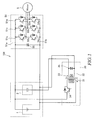
- a power supply device 100 according to a first embodiment of the present invention is described below with reference to FIGS. 1 and 2 .
- the power supply device 100 supplies power to a load by combining a secondary battery 1 and a capacitor 2 connected in parallel to the secondary battery 1.
- the load is an inverter 50 for driving an electric motor 5 by the supply of power from the secondary battery 1 and the capacitor 2.
- the power supply device 100 is applied to an HEV (Hybrid Electric Vehicle), an EV (Electric Vehicle) and the like.
- the inverter 50 to which power is supplied from the power supply device 100 and the electric motor 5 to be driven by the inverter 50 are described.
- the electric motor 5 is a drive motor mounted in an HEV or an EV.
- the electric motor 5 is a three-phase induction motor generator which is driven by a rotating magnetic field generated by a three-phase alternating current.
- the electric motor 5 is provided with a stator including a plurality of coils (not shown) constituting each of a U-phase, a V-phase and a W-phase on an inner periphery and a rotator including a permanent magnet and configured to rotate on the inner periphery of the stator.
- the electric motor 5 is such that the stator is fixed to a vehicle body (not shown) and a rotary shaft of the rotator is coupled to an axle of wheels (not shown).
- the electric motor 5 can convert electrical energy into the rotation of the wheels and can convert the rotation of the wheels into electrical energy.
- the inverter 50 is a voltage-to-current converter for generating alternating current power from direct current power supplied from the secondary battery 1 and the capacitor 2.
- the inverter 50 has a rated voltage of 600 V and a drivable minimum voltage of 300 V. This minimum voltage corresponds to a minimum voltage capable of driving the load.
- the inverter 50 converts the direct current power supplied from the secondary battery 1 and the capacitor 2 into a three-phase alternating current composed of a U-phase, a V-phase and a W-phase shifted at an interval of 120° and supplies it to the electric motor 5.
- the inverter 50 includes a positive-side power line 51a, a negative-side power line 51b, a U-phase power line 51u, a V-phase power line 51v and a W-phase power line 51w.
- the positive-side power line 51a is connected to positive electrodes of the secondary battery 1 and the capacitor 2.
- the negative-side power line 51b is connected to negative electrodes of the secondary battery 1 and the capacitor 2.
- the U-phase power line 51u, the V-phase power line 51v, and the W-phase power line 51w are provided between the positive-side power line 51a and the negative-side power line 51b.
- a smoothing condenser 55 for smoothing a voltage of a direct current transferred between the secondary battery 1, the capacitor 2, and the inverter 50 is connected in parallel between the positive-side power line 51a and the negative-side power line 51b.
- the inverter 50 includes IGBTs (Insulated Gate Bipolar Transistors) 53u, 54u, 53v, 54v, 53w and 54w as six switching elements. These IGBTs 53u to 54w are each an IGBT with a rectifying diode connected in parallel in an opposite direction.
- IGBTs 53u to 54w are each an IGBT with a rectifying diode connected in parallel in an opposite direction.
- the IGBT 53u and the IGBT 54u are provided in series in the U-phase power line 51u.
- the U-phase power line 51u between the IGBT 53u and the IGBT 54u is connected to the coil constituting the U-phase of the electric motor 5.
- the IGBT 53v and the IGBT 54v are provided in series in the V-phase power line 51v.
- the V-phase power line 51v between the IGBT 53v and the IGBT 54v is connected to the coil constituting the V-phase of the electric motor 5.
- the IGBT 53w and the IGBT 54w are provided in series in the W-phase power line 51w.
- the W-phase power line 51w between the IGBT 53w and the IGBT 54w is connected to the coil constituting the W-phase of the electric motor 5.
- the inverter 50 generates an alternating current to drive the electric motor 5 by the IGBTs 53u, 54u, 53v, 54v, 53w and 54w being controlled by a motor controller (not shown).
- the power supply device 100 includes the secondary battery 1, the capacitor 2, an insulation type DC-DC converter (hereinafter, merely referred to as a "DC-DC converter") 30 for applying a bias voltage to the capacitor 2 by utilizing electrical energy of the secondary battery 1, and a controller 40 (see FIG. 2 ) for controlling the DC-DC converter 30.
- DC-DC converter insulation type DC-DC converter
- the secondary battery 1 is a chemical battery such as a lithium ion secondary battery or a nickel hydrogen secondary battery.
- a voltage of the secondary battery 1 is set at 600 V.
- the secondary battery 1 includes a secondary battery voltage detector 1a (see FIG. 2 ) for detecting a voltage and transmitting a corresponding signal to the controller 40.
- the capacitor 2 is an electric double-layer capacitor in which a plurality of capacitor cells are connected in series and set at a desired voltage and a plurality of capacitor cells are connected in parallel and set at a desired storage capacity.
- a voltage of the capacitor 2 is set at 300 V.
- the capacitor 2 includes a capacitor voltage detector 2a (see FIG. 2 ) for detecting a voltage and transmitting a corresponding signal to the controller 40.
- the DC-DC converter 30 includes a primary coil 31 connected in parallel to the secondary battery 1, a secondary coil 32 connected in series to the capacitor 2, a transformer core 33 for accumulating energy by a current flowing in the primary coil 31, an IGBT 34 as a switching element provided in series to the primary coil 31, and a smoothing condenser 35 connected in parallel to the secondary coil 32.
- the DC-DC converter 30 is a flyback converter for adjusting an output voltage to be output from the secondary coil 32 so that the sum of the output voltage and the voltage of the capacitor 2 becomes a set voltage.
- a current from the secondary battery 1 is directly supplied to the primary coil 31.
- the current intermittently flows into the primary coil 31 by the IGBT 34 being switched by the controller 40.
- the primary coil 31 accumulates energy in the transformer core 33 by the current supplied from the secondary battery 1.
- the transformer core 33 is magnetized by the current flowing in the primary coil 31 when the IGBT 34 is switched on. In this way, magnetic energy is accumulated in the transformer core 33. The magnetic energy accumulated in the transformer core 33 is converted into an induction current flowing in the secondary coil 32 when the IGBT 34 is switched off.
- the induction current flows into the secondary coil 32 from the primary coil 31 by the energy accumulated in the transformer core 33.
- the induction current having a lower voltage than that of the secondary battery 1 flows into the secondary coil 32. That is, the DC-DC converter 30 is a step-down converter.
- the IGBT 34 is chopper-controlled by the controller 40.
- the IGBT 34 adjusts the voltage of the induction current flowing in the secondary coil 32 by changing a duty ratio of a chopper control.
- the induction current flowing in the secondary coil 32 has a higher voltage as the duty ratio of the IGBT 34 becomes higher.
- the smoothing condenser 35 smoothes the voltage of the induction current intermittently flowing in the secondary coil 32 by the chopper control of the IGBT 34. In this way, the induction current flowing in the secondary coil 32 becomes a direct current having a substantially constant voltage.
- the controller 40 controls the power supply device 100.
- the controller 40 is a microcomputer with a CPU (Central Processing Unit), a ROM (Read-Only Memory), a RAM (Random Access Memory), and an I/O interface (Input/Output interface).
- the RAM stores data in the process of the CPU.
- the ROM stores a control program of the CPU and the like in advance.
- the I/O interface is used to input and output information from and to a connected device. By operating the CPU, the RAM and the like in accordance with the program stored in the ROM, the control of the power supply device 100 is realized.
- the controller 40 controls the DC-DC converter 30 to adjust an output voltage to be output from the secondary coil 32 so that the sum of the output voltage and the voltage of the capacitor 2 becomes equal to the voltage of the secondary battery 1.
- This voltage of the current to be output from the secondary coil 32 corresponds to the set voltage. In this way, the following control is possible in the power supply device 100.
- the controller 40 controls the DC-DC converter 30 to step down the voltage of the secondary battery 1 to 300 V and apply a bias voltage to the capacitor 2 from the secondary coil 32. In this way, the sum of the voltage of the capacitor 2 and the bias voltage becomes 600 V and becomes equal to the voltage of the secondary battery 1.
- the electric motor 5 can be driven by supplying power to the inverter 50 from the secondary battery 1 and the capacitor 2.
- the controller 40 controls the DC-DC converter 30 to step down the voltage of the secondary battery 1 to a voltage higher than 300 V by a voltage drop of the capacitor 2.
- the controller 40 controls the DC-DC converter 30 to step down the voltage of the secondary battery 1 from 600 V to 350 V and apply a bias voltage to the capacitor 2 from the secondary coil 32. In this way, the sum of the voltage of the capacitor 2 and the bias voltage becomes 600 V and becomes equal to the voltage of the secondary battery 1.
- the electric motor 5 can be driven by supplying power to the inverter 50 from the secondary battery 1 and the capacitor 2.
- the controller 40 controls the DC-DC converter 30 to apply a bias voltage of approximately 600 V to the capacitor 2 from the secondary coil 32 while hardly stepping down the voltage of the secondary battery 1. In this way, the sum of the voltage of the capacitor 2 and the bias voltage can be set at 600 V.
- the electric motor 5 can be driven by supplying power to the inverter 50 until the voltage of the capacitor 2 becomes substantially 0 V.
- a bias voltage can be applied to the capacitor 2 from the secondary battery 1 by controlling the DC-DC converter 30 when the voltage of the capacitor 2 drops.
- the electric motor 5 can be driven by supplying the electrical energy remaining in the capacitor 2 to the inverter 50 by increasing an apparent voltage by the bias voltage even if the voltage of the capacitor 2 drops. Therefore, the electrical energy of the capacitor 2 can be effectively utilized.
- the capacitor 2 can be reduced in size and weight. Specifically, as compared with the case where a capacitor of 600 V is used until a voltage drops to 300 V, the capacitor 2 can output equivalent electrical energy with a capacity smaller by about 25 %. Thus, the weight and installation space of the capacitor 2 are reduced by about 25 % and cost can be reduced by that much.
- the bias voltage can be applied to the capacitor 2 from the secondary battery 1 by the DC-DC converter 30.
- the electric motor 5 can be driven by supplying the electrical energy remaining in the capacitor 2 to the inverter 50 by increasing the apparent voltage by the bias voltage. Therefore, the electrical energy of the capacitor 2 can be effectively utilized.
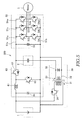
- a power supply device 200 according to a second embodiment of the present invention is described below with reference to FIGS. 3 and 4 . It should be noted that, in each of the following embodiments, components similar to those of the aforementioned embodiment are denoted by the same reference signs and repeated description is omitted as appropriate.
- the second embodiment differs from the first embodiment in including a non-insulation type DC-DC converter (hereinafter, merely referred to as a "DC-DC converter") 60 capable of supplying a current to an inverter 50 by stepping up a voltage of a secondary battery 1.
- a DC-DC converter non-insulation type DC-DC converter
- the power supply device 200 supplies power to the inverter 50 by combining the secondary battery 1 and a capacitor 2 connected in parallel to the secondary battery 1.
- the power supply device 200 is provided with the secondary battery 1, the capacitor 2, the DC-DC converter 60 capable of supplying a current to the inverter 50 by stepping up a voltage of the secondary battery 1, a DC-DC converter 30 for applying a bias voltage to the capacitor 2 by utilizing electrical energy of the secondary battery 1, and a controller 40 (see FIG. 4 ) for controlling the DC-DC converters 60 and 30.
- the DC-DC converter 60 can supply power to the inverter 50 by stepping up the voltage of the secondary battery 1 and can step down regenerative power from the inverter 50 and charge it into the secondary battery 1.
- the DC-DC converter 60 includes a reactor 61 provided downstream of the secondary battery 1, a step-down control transistor 62 provided between the reactor 61 and an upstream side of an electric motor 5, a step-up control transistor 63 provided between the reactor 61 and a downstream side of the electric motor 5, and a smoothing condenser 64 connected in parallel to the secondary battery 1.
- the reactor 61 accumulates energy when the step-up control transistor 63 is on. When the step-up control transistor 63 is turned off, an induced electromotive force by the voltage input from the secondary battery 1 and the energy accumulated in the reactor 61 is output. In this way, the reactor 61 can step up and output the input voltage by the switching of the step-up control transistor 63.
- the step-up control transistor 63 is switched by the controller 40.
- the step-up control transistor 63 is an IGBT with a rectifying diode connected in parallel in an opposite direction.
- the step-up control transistor 63 can step up a supply voltage to be supplied to the electric motor 5 by the induced electromotive force by switching a current of the reactor 61.
- step-up control transistor 63 When the step-up control transistor 63 is switched on, a current from a positive electrode of the secondary battery 1 flows to a negative electrode of the secondary battery 1 by way of the reactor 61 and the step-up control transistor 63. By this current loop, energy is accumulated in the reactor 61.
- the step-down control transistor 62 is switched by the controller 40.
- the step-down control transistor 62 is an IGBT with a rectifying diode connected in parallel in an opposite direction.
- the step-down control transistor 62 can step down a charge voltage from the electric motor 5 by switching.
- the step-down control transistor 62 steps down the power generated by the electric motor 5 by a chopper control and charges it into the secondary battery 1.
- the smoothing condenser 64 smoothes a voltage output by the chopper control of the step-down control transistor 62. In this way, a voltage when the power generated by the electric motor 5, is charged into the secondary battery 1 and can be smoothed and stabilized.
- the DC-DC converter 30 includes a primary coil 31 connected in parallel to the secondary battery 1, a secondary coil 32 connected in series to the capacitor 2, a transformer core 33 for accumulating energy by a current flowing in the primary coil 31, an IGBT 34 as a switching element provided in series to the primary coil 31, and a smoothing condenser 35 connected in parallel to the secondary coil 32.
- the DC-DC converter 30 is similar to that of the first embodiment. Here, the configuration of the DC-DC converter 30 is not described in detail.
- a current of the secondary battery 1 stepped up by the DC-DC converter 60 is directly supplied to the primary coil 31.
- the magnitude of a bias voltage applied to the capacitor 2 from the secondary coil 32 is adjusted by a coordinated control of the DC-DC converters 30 and 60. Therefore, the magnitude of the bias voltage applied to the capacitor 2 from the secondary coil 32 can be more finely adjusted.
- the bias voltage when the voltage of the capacitor 2 drops, the bias voltage can be applied to the capacitor 2 from the secondary battery 1 by the coordinated control of the DC-DC converters 30, 60.
- the electric motor 5 can be driven by supplying the electrical energy remaining in the capacitor 2 to the inverter 50 by increasing an apparent voltage by the bias voltage even if the voltage of the capacitor 2 drops. Therefore, the electrical energy of the capacitor 2 can be effectively utilized.
- the DC-DC converter 60 capable of supplying a current to the inverter 50 by stepping up the voltage of the secondary battery 1, it is possible to use the secondary battery 1 having a lower voltage as compared with the first embodiment.
- the weight and installation space of the capacitor 2 are reduced, the weight and installation space of the secondary battery 1 are also reduced and cost can be reduced by that much.
- the controller 40 operates the DC-DC converter 60 to step down the electrical energy generated by the electric motor 5 and charge it into the secondary battery 1. At this time, since the voltage and the current can be adjusted to those suitable for the charging of the secondary battery 1, the secondary battery 1 can be efficiently charged.
- a power supply device 300 according to a third embodiment of the present invention is described below with reference to FIG. 5 .
- the third embodiment is common to the second embodiment in including a DC-DC converter 60, but differs therefrom in that a current from a secondary battery 1 is directly supplied to a primary coil 31.
- the power supply device 300 supplies power to an inverter 50 by combining the secondary battery 1 and a capacitor 2 connected in parallel to the secondary battery 1.
- the power supply device 300 is provided with the secondary battery 1, the capacitor 2, the DC-DC converter 60 capable of supplying a current to the inverter 50 by stepping up a voltage of the secondary battery 1, a DC-DC converter 30 for applying a bias voltage to the capacitor 2 by utilizing electrical energy of the secondary battery 1 and a controller 40 (see FIG. 4 ) for controlling the DC-DC converters 60 and 30.
- the current of the secondary battery 1 is directly supplied to the primary coil 31 without the DC-DC converter 60. This enables the following control to be executed in the power supply device 300.
- the controller 40 sets both the DC-DC converter 60 and the DC-DC converter 30 to a non-operational state. In this way, power is supplied to the inverter 50 from the capacitor 2 to drive the electric motor 5.
- the controller 40 controls the DC-DC converter 30 to apply a bias voltage to the capacitor 2 from the secondary coil 32, while the DC-DC converter 60 is kept in the non-operational state. In this way, even if the voltage of the capacitor 2 drops, the electric motor 5 can be driven by supplying electrical energy remaining in the capacitor 2 to the inverter 50 by increasing an apparent voltage by the bias voltage. Thus, the electrical energy of the capacitor 2 can be effectively utilized.
- the controller 40 executes a control to step up the DC-DC converter 60, while the DC-DC converter 30 is kept in the non-operational state.
- the electric motor 5 can be driven by stepping up the voltage of the secondary battery 1 and supplying it to the inverter 50. It should be noted that, at this time, the voltage of the secondary battery 1 needs to be stepped up to be equal to that of the capacitor 2 by controlling the DC-DC converter 60.
- the bias voltage when the voltage of the capacitor 2 drops, the bias voltage can be applied to the capacitor 2 from the secondary battery 1 by the DC-DC converter 30.
- the electric motor 5 can be driven by supplying the electrical energy remaining in the capacitor 2 to the inverter 50 by increasing an apparent voltage by the bias voltage even if the voltage of the capacitor 2 drops. Therefore, the electrical energy of the capacitor 2 can be effectively utilized.
- DC-DC converters 60 and 30 it is possible both to supply power to the inverter 50 only from the secondary battery 1 and to supply power to the inverter 50 only from the capacitor 2.
- the power supply device 100, 200, 300 is controlled by the controller 40 and the inverter 50 is controlled by the motor controller (not shown).
- the power supply device 100, 200, 300 and the inverter 50 may be controlled by a single controller.
- each of the aforementioned IGBTs is an IGBT with a rectifying diode connected in parallel in an opposite direction.
- an IGBT incorporating no diode and a rectifying diode connected in parallel to the IGBT in an opposite direction may be separately provided.
- other transistors such as MOSFETs (Metal-Oxide-Semiconductor Field-Effect Transistors) may be used as switching elements.
Landscapes
- Engineering & Computer Science (AREA)
- Power Engineering (AREA)
- Transportation (AREA)
- Mechanical Engineering (AREA)
- Life Sciences & Earth Sciences (AREA)
- Sustainable Development (AREA)
- Sustainable Energy (AREA)
- Chemical Kinetics & Catalysis (AREA)
- Chemical & Material Sciences (AREA)
- Electrochemistry (AREA)
- General Chemical & Material Sciences (AREA)
- Manufacturing & Machinery (AREA)
- Dc-Dc Converters (AREA)
- Electric Propulsion And Braking For Vehicles (AREA)
- Inverter Devices (AREA)
- Charge And Discharge Circuits For Batteries Or The Like (AREA)
Abstract
Description
- The present invention relates to a power supply device for supplying power to a load.
- Conventionally, a power supply device for supplying power to a load by combining a battery and a capacitor has been used.
JP2006-345606A - However, in the power supply system of
JP2006-345606A - The present invention was developed in view of the above problem and aims to effectively utilize electrical energy of a capacitor.
- According to one aspect of the present invention, a power supply device configured to supply power to a load by combining a secondary battery and a capacitor connected in parallel to the secondary battery, the power supply device includes an insulation type DC-DC converter including a primary coil and a secondary coil, the primary coil being connected in parallel to the secondary battery, the primary coil being configured to accumulate energy by a current supplied from the secondary battery, the secondary coil being connected in series to the capacitor, the secondary coil being configured such that an induction current flows therein by the accumulated energy from the primary coil.
- The details as well as other features and advantages of this invention are set forth in the remainder of the specification and are shown in the accompanying drawings.
-
-
FIG. 1 is an electrical circuit diagram of a power supply device according to a first embodiment of the present invention, -
FIG. 2 is a block diagram of the power supply device according to the first embodiment of the present invention, -
FIG. 3 is an electrical circuit diagram of a power supply device according to a second embodiment of the present invention, -
FIG. 4 is a block diagram of the power supply device according to the second embodiment of the present invention, and -
FIG. 5 is an electrical circuit diagram of a power supply device according to a third embodiment of the present invention. - Hereinafter, embodiments of the present invention are described with reference to the drawings.
- A
power supply device 100 according to a first embodiment of the present invention is described below with reference toFIGS. 1 and2 . - The
power supply device 100 supplies power to a load by combining asecondary battery 1 and acapacitor 2 connected in parallel to thesecondary battery 1. The load is aninverter 50 for driving anelectric motor 5 by the supply of power from thesecondary battery 1 and thecapacitor 2. Thepower supply device 100 is applied to an HEV (Hybrid Electric Vehicle), an EV (Electric Vehicle) and the like. - First, the
inverter 50 to which power is supplied from thepower supply device 100 and theelectric motor 5 to be driven by theinverter 50 are described. - The
electric motor 5 is a drive motor mounted in an HEV or an EV. Theelectric motor 5 is a three-phase induction motor generator which is driven by a rotating magnetic field generated by a three-phase alternating current. Theelectric motor 5 is provided with a stator including a plurality of coils (not shown) constituting each of a U-phase, a V-phase and a W-phase on an inner periphery and a rotator including a permanent magnet and configured to rotate on the inner periphery of the stator. Theelectric motor 5 is such that the stator is fixed to a vehicle body (not shown) and a rotary shaft of the rotator is coupled to an axle of wheels (not shown). Theelectric motor 5 can convert electrical energy into the rotation of the wheels and can convert the rotation of the wheels into electrical energy. - The
inverter 50 is a voltage-to-current converter for generating alternating current power from direct current power supplied from thesecondary battery 1 and thecapacitor 2. Theinverter 50 has a rated voltage of 600 V and a drivable minimum voltage of 300 V. This minimum voltage corresponds to a minimum voltage capable of driving the load. - The
inverter 50 converts the direct current power supplied from thesecondary battery 1 and thecapacitor 2 into a three-phase alternating current composed of a U-phase, a V-phase and a W-phase shifted at an interval of 120° and supplies it to theelectric motor 5. - The
inverter 50 includes a positive-side power line 51a, a negative-side power line 51b, aU-phase power line 51u, a V-phase power line 51v and a W-phase power line 51w. The positive-side power line 51a is connected to positive electrodes of thesecondary battery 1 and thecapacitor 2. The negative-side power line 51b is connected to negative electrodes of thesecondary battery 1 and thecapacitor 2. The U-phasepower line 51u, the V-phase power line 51v, and the W-phase power line 51w are provided between the positive-side power line 51a and the negative-side power line 51b. Further, asmoothing condenser 55 for smoothing a voltage of a direct current transferred between thesecondary battery 1, thecapacitor 2, and theinverter 50 is connected in parallel between the positive-side power line 51a and the negative-side power line 51b. - The
inverter 50 includes IGBTs (Insulated Gate Bipolar Transistors) 53u, 54u, 53v, 54v, 53w and 54w as six switching elements. TheseIGBTs 53u to 54w are each an IGBT with a rectifying diode connected in parallel in an opposite direction. - The IGBT 53u and the IGBT 54u are provided in series in the
U-phase power line 51u. The U-phasepower line 51u between the IGBT 53u and the IGBT 54u is connected to the coil constituting the U-phase of theelectric motor 5. TheIGBT 53v and theIGBT 54v are provided in series in the V-phase power line 51v. The V-phase power line 51v between theIGBT 53v and theIGBT 54v is connected to the coil constituting the V-phase of theelectric motor 5. TheIGBT 53w and theIGBT 54w are provided in series in the W-phase power line 51w. The W-phase power line 51w between theIGBT 53w and theIGBT 54w is connected to the coil constituting the W-phase of theelectric motor 5. - The
inverter 50 generates an alternating current to drive theelectric motor 5 by theIGBTs - Next, the configuration of the
power supply device 100 is described. - The
power supply device 100 includes thesecondary battery 1, thecapacitor 2, an insulation type DC-DC converter (hereinafter, merely referred to as a "DC-DC converter") 30 for applying a bias voltage to thecapacitor 2 by utilizing electrical energy of thesecondary battery 1, and a controller 40 (seeFIG. 2 ) for controlling the DC-DC converter 30. - The
secondary battery 1 is a chemical battery such as a lithium ion secondary battery or a nickel hydrogen secondary battery. Here, a voltage of thesecondary battery 1 is set at 600 V. Thesecondary battery 1 includes a secondarybattery voltage detector 1a (seeFIG. 2 ) for detecting a voltage and transmitting a corresponding signal to thecontroller 40. - The
capacitor 2 is an electric double-layer capacitor in which a plurality of capacitor cells are connected in series and set at a desired voltage and a plurality of capacitor cells are connected in parallel and set at a desired storage capacity. Here, a voltage of thecapacitor 2 is set at 300 V. Thecapacitor 2 includes acapacitor voltage detector 2a (seeFIG. 2 ) for detecting a voltage and transmitting a corresponding signal to thecontroller 40. - The DC-
DC converter 30 includes aprimary coil 31 connected in parallel to thesecondary battery 1, asecondary coil 32 connected in series to thecapacitor 2, atransformer core 33 for accumulating energy by a current flowing in theprimary coil 31, anIGBT 34 as a switching element provided in series to theprimary coil 31, and asmoothing condenser 35 connected in parallel to thesecondary coil 32. The DC-DC converter 30 is a flyback converter for adjusting an output voltage to be output from thesecondary coil 32 so that the sum of the output voltage and the voltage of thecapacitor 2 becomes a set voltage. - A current from the
secondary battery 1 is directly supplied to theprimary coil 31. The current intermittently flows into theprimary coil 31 by the IGBT 34 being switched by thecontroller 40. Theprimary coil 31 accumulates energy in thetransformer core 33 by the current supplied from thesecondary battery 1. - The
transformer core 33 is magnetized by the current flowing in theprimary coil 31 when the IGBT 34 is switched on. In this way, magnetic energy is accumulated in thetransformer core 33. The magnetic energy accumulated in thetransformer core 33 is converted into an induction current flowing in thesecondary coil 32 when theIGBT 34 is switched off. - The induction current flows into the
secondary coil 32 from theprimary coil 31 by the energy accumulated in thetransformer core 33. The induction current having a lower voltage than that of thesecondary battery 1 flows into thesecondary coil 32. That is, the DC-DC converter 30 is a step-down converter. - The
IGBT 34 is chopper-controlled by thecontroller 40. TheIGBT 34 adjusts the voltage of the induction current flowing in thesecondary coil 32 by changing a duty ratio of a chopper control. The induction current flowing in thesecondary coil 32 has a higher voltage as the duty ratio of theIGBT 34 becomes higher. - The smoothing
condenser 35 smoothes the voltage of the induction current intermittently flowing in thesecondary coil 32 by the chopper control of theIGBT 34. In this way, the induction current flowing in thesecondary coil 32 becomes a direct current having a substantially constant voltage. - The controller 40 (see
FIG. 2 ) controls thepower supply device 100. Thecontroller 40 is a microcomputer with a CPU (Central Processing Unit), a ROM (Read-Only Memory), a RAM (Random Access Memory), and an I/O interface (Input/Output interface). The RAM stores data in the process of the CPU. The ROM stores a control program of the CPU and the like in advance. The I/O interface is used to input and output information from and to a connected device. By operating the CPU, the RAM and the like in accordance with the program stored in the ROM, the control of thepower supply device 100 is realized. - The
controller 40 controls the DC-DC converter 30 to adjust an output voltage to be output from thesecondary coil 32 so that the sum of the output voltage and the voltage of thecapacitor 2 becomes equal to the voltage of thesecondary battery 1. This voltage of the current to be output from thesecondary coil 32 corresponds to the set voltage. In this way, the following control is possible in thepower supply device 100. - Next, functions of the
power supply device 100 are described. - When the
secondary battery 1 and thecapacitor 2 are both fully charged, thecontroller 40 controls the DC-DC converter 30 to step down the voltage of thesecondary battery 1 to 300 V and apply a bias voltage to thecapacitor 2 from thesecondary coil 32. In this way, the sum of the voltage of thecapacitor 2 and the bias voltage becomes 600 V and becomes equal to the voltage of thesecondary battery 1. Thus, theelectric motor 5 can be driven by supplying power to theinverter 50 from thesecondary battery 1 and thecapacitor 2. - When the
electric motor 5 is driven by supplying power to theinverter 50 from thecapacitor 2, the voltage of thecapacitor 2 proportionally drops. At this time, thecontroller 40 controls the DC-DC converter 30 to step down the voltage of thesecondary battery 1 to a voltage higher than 300 V by a voltage drop of thecapacitor 2. - Specifically, if the voltage of the
capacitor 2 drops, for example, to 250 V, thecontroller 40 controls the DC-DC converter 30 to step down the voltage of thesecondary battery 1 from 600 V to 350 V and apply a bias voltage to thecapacitor 2 from thesecondary coil 32. In this way, the sum of the voltage of thecapacitor 2 and the bias voltage becomes 600 V and becomes equal to the voltage of thesecondary battery 1. Thus, also in this case, theelectric motor 5 can be driven by supplying power to theinverter 50 from thesecondary battery 1 and thecapacitor 2. - If the supply of power to the
inverter 50 by thesecondary battery 1 and thecapacitor 2 continues, the voltage of thecapacitor 2 drops and approaches 0 V. At this time, thecontroller 40 controls the DC-DC converter 30 to apply a bias voltage of approximately 600 V to thecapacitor 2 from thesecondary coil 32 while hardly stepping down the voltage of thesecondary battery 1. In this way, the sum of the voltage of thecapacitor 2 and the bias voltage can be set at 600 V. Thus, theelectric motor 5 can be driven by supplying power to theinverter 50 until the voltage of thecapacitor 2 becomes substantially 0 V. - Conventionally, it has not been possible to drive the
inverter 50 by utilizing electrical energy of thecapacitor 2 although the electrical energy remains in thecapacitor 2 if the voltage of thecapacitor 2 drops below the minimum voltage capable of driving theinverter 50. Since the minimum voltage capable of driving theinverter 50 is 300 V, it has not been possible to drive theinverter 50 by using the electrical energy of thecapacitor 2 if the voltage of thecapacitor 2 drops below 300 V. - Contrary to this, in the
power supply device 100, a bias voltage can be applied to thecapacitor 2 from thesecondary battery 1 by controlling the DC-DC converter 30 when the voltage of thecapacitor 2 drops. Thus, theelectric motor 5 can be driven by supplying the electrical energy remaining in thecapacitor 2 to theinverter 50 by increasing an apparent voltage by the bias voltage even if the voltage of thecapacitor 2 drops. Therefore, the electrical energy of thecapacitor 2 can be effectively utilized. - Further, since the electrical energy of the
capacitor 2 can be effectively utilized, the capacity of thecapacitor 2 necessary to output the same electrical energy to theinverter 50 can be reduced. Thus, thecapacitor 2 can be reduced in size and weight. Specifically, as compared with the case where a capacitor of 600 V is used until a voltage drops to 300 V, thecapacitor 2 can output equivalent electrical energy with a capacity smaller by about 25 %. Thus, the weight and installation space of thecapacitor 2 are reduced by about 25 % and cost can be reduced by that much. - According to the above first embodiment, the following effects are exhibited.
- When the voltage of the
capacitor 2 drops, the bias voltage can be applied to thecapacitor 2 from thesecondary battery 1 by the DC-DC converter 30. Thus, even if the voltage of thecapacitor 2 drops, theelectric motor 5 can be driven by supplying the electrical energy remaining in thecapacitor 2 to theinverter 50 by increasing the apparent voltage by the bias voltage. Therefore, the electrical energy of thecapacitor 2 can be effectively utilized. - A
power supply device 200 according to a second embodiment of the present invention is described below with reference toFIGS. 3 and4 . It should be noted that, in each of the following embodiments, components similar to those of the aforementioned embodiment are denoted by the same reference signs and repeated description is omitted as appropriate. - The second embodiment differs from the first embodiment in including a non-insulation type DC-DC converter (hereinafter, merely referred to as a "DC-DC converter") 60 capable of supplying a current to an
inverter 50 by stepping up a voltage of asecondary battery 1. - The
power supply device 200 supplies power to theinverter 50 by combining thesecondary battery 1 and acapacitor 2 connected in parallel to thesecondary battery 1. - The
power supply device 200 is provided with thesecondary battery 1, thecapacitor 2, the DC-DC converter 60 capable of supplying a current to theinverter 50 by stepping up a voltage of thesecondary battery 1, a DC-DC converter 30 for applying a bias voltage to thecapacitor 2 by utilizing electrical energy of thesecondary battery 1, and a controller 40 (seeFIG. 4 ) for controlling the DC-DC converters - The DC-
DC converter 60 can supply power to theinverter 50 by stepping up the voltage of thesecondary battery 1 and can step down regenerative power from theinverter 50 and charge it into thesecondary battery 1. The DC-DC converter 60 includes areactor 61 provided downstream of thesecondary battery 1, a step-downcontrol transistor 62 provided between thereactor 61 and an upstream side of anelectric motor 5, a step-upcontrol transistor 63 provided between thereactor 61 and a downstream side of theelectric motor 5, and a smoothingcondenser 64 connected in parallel to thesecondary battery 1. - The
reactor 61 accumulates energy when the step-upcontrol transistor 63 is on. When the step-upcontrol transistor 63 is turned off, an induced electromotive force by the voltage input from thesecondary battery 1 and the energy accumulated in thereactor 61 is output. In this way, thereactor 61 can step up and output the input voltage by the switching of the step-upcontrol transistor 63. - The step-up
control transistor 63 is switched by thecontroller 40. The step-upcontrol transistor 63 is an IGBT with a rectifying diode connected in parallel in an opposite direction. The step-upcontrol transistor 63 can step up a supply voltage to be supplied to theelectric motor 5 by the induced electromotive force by switching a current of thereactor 61. - When the step-up
control transistor 63 is switched on, a current from a positive electrode of thesecondary battery 1 flows to a negative electrode of thesecondary battery 1 by way of thereactor 61 and the step-upcontrol transistor 63. By this current loop, energy is accumulated in thereactor 61. - The step-down
control transistor 62 is switched by thecontroller 40. The step-downcontrol transistor 62 is an IGBT with a rectifying diode connected in parallel in an opposite direction. The step-downcontrol transistor 62 can step down a charge voltage from theelectric motor 5 by switching. The step-downcontrol transistor 62 steps down the power generated by theelectric motor 5 by a chopper control and charges it into thesecondary battery 1. - The smoothing
condenser 64 smoothes a voltage output by the chopper control of the step-downcontrol transistor 62. In this way, a voltage when the power generated by theelectric motor 5, is charged into thesecondary battery 1 and can be smoothed and stabilized. - The DC-
DC converter 30 includes aprimary coil 31 connected in parallel to thesecondary battery 1, asecondary coil 32 connected in series to thecapacitor 2, atransformer core 33 for accumulating energy by a current flowing in theprimary coil 31, anIGBT 34 as a switching element provided in series to theprimary coil 31, and a smoothingcondenser 35 connected in parallel to thesecondary coil 32. The DC-DC converter 30 is similar to that of the first embodiment. Here, the configuration of the DC-DC converter 30 is not described in detail. - A current of the
secondary battery 1 stepped up by the DC-DC converter 60 is directly supplied to theprimary coil 31. Thus, the magnitude of a bias voltage applied to thecapacitor 2 from thesecondary coil 32 is adjusted by a coordinated control of the DC-DC converters capacitor 2 from thesecondary coil 32 can be more finely adjusted. - According to the above second embodiment, when the voltage of the
capacitor 2 drops, the bias voltage can be applied to thecapacitor 2 from thesecondary battery 1 by the coordinated control of the DC-DC converters electric motor 5 can be driven by supplying the electrical energy remaining in thecapacitor 2 to theinverter 50 by increasing an apparent voltage by the bias voltage even if the voltage of thecapacitor 2 drops. Therefore, the electrical energy of thecapacitor 2 can be effectively utilized. - Further, by providing the DC-
DC converter 60 capable of supplying a current to theinverter 50 by stepping up the voltage of thesecondary battery 1, it is possible to use thesecondary battery 1 having a lower voltage as compared with the first embodiment. Thus, the weight and installation space of thecapacitor 2 are reduced, the weight and installation space of thesecondary battery 1 are also reduced and cost can be reduced by that much. - It should be noted that, at the time of braking a vehicle, the electrical energy generated by the
electric motor 5 is first charged into thecapacitor 2. When thecapacitor 2 is fully charged, thecontroller 40 operates the DC-DC converter 60 to step down the electrical energy generated by theelectric motor 5 and charge it into thesecondary battery 1. At this time, since the voltage and the current can be adjusted to those suitable for the charging of thesecondary battery 1, thesecondary battery 1 can be efficiently charged. - A
power supply device 300 according to a third embodiment of the present invention is described below with reference toFIG. 5 . - The third embodiment is common to the second embodiment in including a DC-
DC converter 60, but differs therefrom in that a current from asecondary battery 1 is directly supplied to aprimary coil 31. - The
power supply device 300 supplies power to aninverter 50 by combining thesecondary battery 1 and acapacitor 2 connected in parallel to thesecondary battery 1. - The
power supply device 300 is provided with thesecondary battery 1, thecapacitor 2, the DC-DC converter 60 capable of supplying a current to theinverter 50 by stepping up a voltage of thesecondary battery 1, a DC-DC converter 30 for applying a bias voltage to thecapacitor 2 by utilizing electrical energy of thesecondary battery 1 and a controller 40 (seeFIG. 4 ) for controlling the DC-DC converters - The current of the
secondary battery 1 is directly supplied to theprimary coil 31 without the DC-DC converter 60. This enables the following control to be executed in thepower supply device 300. - Next, functions of the
power supply device 300 are described. - In the case of supplying power to the
inverter 50 from thecapacitor 2 in a state where thecapacitor 2 is fully charged, thecontroller 40 sets both the DC-DC converter 60 and the DC-DC converter 30 to a non-operational state. In this way, power is supplied to theinverter 50 from thecapacitor 2 to drive theelectric motor 5. - When the
electric motor 5 is driven by supplying power to theinverter 50 from thecapacitor 2, the voltage of thecapacitor 2 proportionally drops. At this time, thecontroller 40 controls the DC-DC converter 30 to apply a bias voltage to thecapacitor 2 from thesecondary coil 32, while the DC-DC converter 60 is kept in the non-operational state. In this way, even if the voltage of thecapacitor 2 drops, theelectric motor 5 can be driven by supplying electrical energy remaining in thecapacitor 2 to theinverter 50 by increasing an apparent voltage by the bias voltage. Thus, the electrical energy of thecapacitor 2 can be effectively utilized. - On the other hand, in the case of supplying power to the
inverter 50 from thesecondary battery 1, thecontroller 40 executes a control to step up the DC-DC converter 60, while the DC-DC converter 30 is kept in the non-operational state. In this way, theelectric motor 5 can be driven by stepping up the voltage of thesecondary battery 1 and supplying it to theinverter 50. It should be noted that, at this time, the voltage of thesecondary battery 1 needs to be stepped up to be equal to that of thecapacitor 2 by controlling the DC-DC converter 60. - If the voltage of the capacitor is not sufficiently high, power is supplied to the
inverter 50 from thesecondary battery 1 by controlling the DC-DC converter 60 and the bias voltage is applied to thecapacitor 2 from thesecondary coil 32 by controlling the DC-DC converter 30. This prevents the power to be supplied to theinverter 50 from thesecondary battery 1 from being charged into thecapacitor 2 without being supplied to theinverter 50. - According to the above third embodiment, when the voltage of the
capacitor 2 drops, the bias voltage can be applied to thecapacitor 2 from thesecondary battery 1 by the DC-DC converter 30. Thus, as in the first and second embodiments, theelectric motor 5 can be driven by supplying the electrical energy remaining in thecapacitor 2 to theinverter 50 by increasing an apparent voltage by the bias voltage even if the voltage of thecapacitor 2 drops. Therefore, the electrical energy of thecapacitor 2 can be effectively utilized. - Further, by providing the DC-
DC converters inverter 50 only from thesecondary battery 1 and to supply power to theinverter 50 only from thecapacitor 2. - Embodiments of this invention were described above, but the above embodiments are merely examples of applications of this invention, and the technical scope of this invention is not limited to the specific constitutions of the above embodiments.
- For example, numerical values such as those of the voltages in the aforementioned embodiments are illustrative and there is no limitation to these numerical values.
- Further, in the aforementioned embodiments, the
power supply device controller 40 and theinverter 50 is controlled by the motor controller (not shown). Instead of this, thepower supply device inverter 50 may be controlled by a single controller. - Further, each of the aforementioned IGBTs is an IGBT with a rectifying diode connected in parallel in an opposite direction. Instead of this, an IGBT incorporating no diode and a rectifying diode connected in parallel to the IGBT in an opposite direction may be separately provided. Further, instead of IGBTs, other transistors such as MOSFETs (Metal-Oxide-Semiconductor Field-Effect Transistors) may be used as switching elements.
- The embodiments of this invention in which an exclusive property or privilege is claimed are defined as follows:
Claims (8)
- A power supply device configured to supply power to a load by combining a secondary battery and a capacitor connected in parallel to the secondary battery, the power supply device comprising:an insulation type DC-DC converter including a primary coil and a secondary coil, the primary coil being connected in parallel to the secondary battery, the primary coil being configured to accumulate energy by a current supplied from the secondary battery, the secondary coil being connected in series to the capacitor, the secondary coil being configured such that an induction current flows therein by the accumulated energy from the primary coil.
- The power supply device according to claim 1, wherein:the insulation type DC-DC converter is a flyback converter, the flyback comberter being configured to adjust an output voltage to be output from the secondary coil so that the sum of the output voltage and a voltage of the capacitor becomes a set voltage.
- The power supply device according to claim 1 or 2, wherein:a current from the secondary battery is directly supplied to the primary coil.
- The power supply device according to claim 3, wherein:the insulation type DC-DC converter configured to adjust an output voltage to be output from the secondary coil so that the sum of the output voltage and a voltage of the capacitor becomes equal to a voltage of the secondary battery.
- The power supply device according to claim 1 or 2, further comprising a non-insulation type DC-DC converter configured to supply a current to the load by stepping up a voltage of the secondary battery, the non-insulation type DC-DC converter charging a regenerated current from the load into the secondary battery by stepping down the regenerated current.
- The power supply device according to claim 5, wherein:the current of the secondary battery stepped up by the non-insulation type DC-DC converter is supplied to the primary coil.
- The power supply device according to claim 5, wherein:the current from the secondary battery is directly supplied to the primary coil without the non-insulation type DC-DC converter.
- The power supply device according to any one of claims 1 to 7, wherein:the load is an inverter configured to drive an electric motor by the supply of power from the secondary battery and the capacitor.
Applications Claiming Priority (1)
| Application Number | Priority Date | Filing Date | Title |
|---|---|---|---|
| PCT/JP2012/081327 WO2014087475A1 (en) | 2012-12-04 | 2012-12-04 | Power supply apparatus |
Publications (3)
| Publication Number | Publication Date |
|---|---|
| EP2930835A1 true EP2930835A1 (en) | 2015-10-14 |
| EP2930835A4 EP2930835A4 (en) | 2016-07-20 |
| EP2930835B1 EP2930835B1 (en) | 2021-02-24 |
Family
ID=50882926
Family Applications (1)
| Application Number | Title | Priority Date | Filing Date |
|---|---|---|---|
| EP12889494.6A Not-in-force EP2930835B1 (en) | 2012-12-04 | 2012-12-04 | Power supply apparatus |
Country Status (5)
| Country | Link |
|---|---|
| US (1) | US9520806B2 (en) |
| EP (1) | EP2930835B1 (en) |
| JP (1) | JP5899330B2 (en) |
| CN (1) | CN104838573B (en) |
| WO (1) | WO2014087475A1 (en) |
Families Citing this family (6)
| Publication number | Priority date | Publication date | Assignee | Title |
|---|---|---|---|---|
| JP5862631B2 (en) * | 2013-10-08 | 2016-02-16 | トヨタ自動車株式会社 | Power storage system |
| US9809119B2 (en) * | 2015-01-13 | 2017-11-07 | General Electric Company | Bi-directional DC-DC power converter for a vehicle system |
| JP6657820B2 (en) * | 2015-11-12 | 2020-03-04 | 三菱自動車工業株式会社 | Vehicle power supply |
| US10862401B2 (en) * | 2018-10-26 | 2020-12-08 | Lear Corporation | Tandem DC/DC converter for a vehicle battery charger |
| US10989760B2 (en) * | 2018-12-27 | 2021-04-27 | Bloom Energy Corporation | System and method for impedance testing DC power sources |
| JP7446390B2 (en) * | 2021-11-08 | 2024-03-08 | 台達電子工業股▲ふん▼有限公司 | Integrated power system with motor drive and battery charging/discharging |
Family Cites Families (14)
| Publication number | Priority date | Publication date | Assignee | Title |
|---|---|---|---|---|
| LU44443A1 (en) * | 1962-09-27 | 1963-11-14 | ||
| US4504896A (en) * | 1981-03-18 | 1985-03-12 | Rca Corporation | Switching dc-to-dc converters |
| JP2002118974A (en) * | 2000-10-03 | 2002-04-19 | Nec Mobile Energy Kk | Battery pack |
| JP2003143713A (en) * | 2001-11-05 | 2003-05-16 | Komatsu Ltd | Hybrid power supply system |
| JP2004140959A (en) * | 2002-10-21 | 2004-05-13 | Toyota Motor Corp | Bidirectional DC-DC converter |
| JP4506571B2 (en) * | 2005-06-07 | 2010-07-21 | トヨタ自動車株式会社 | Vehicle power supply system and vehicle |
| US7649335B2 (en) | 2005-06-07 | 2010-01-19 | Toyota Jidosha Kabushiki Kaisha | Vehicular power supply system and vehicle |
| US7990098B2 (en) * | 2007-07-30 | 2011-08-02 | GM Global Technology Operations LLC | Series-coupled two-motor drive using double-ended inverter system |
| JP5487675B2 (en) * | 2009-03-30 | 2014-05-07 | 富士電機株式会社 | Motor drive device and electric vehicle |
| JP4960407B2 (en) * | 2009-05-20 | 2012-06-27 | 三菱電機株式会社 | Vehicle drive power supply |
| TW201143267A (en) * | 2010-05-31 | 2011-12-01 | Univ Nat Cheng Kung | Multi-winding high step-up DC-DC converter |
| US8368362B2 (en) * | 2010-09-02 | 2013-02-05 | National Formosa University | Boost-forward-flyback high gain converter |
| WO2012140746A1 (en) * | 2011-04-13 | 2012-10-18 | トヨタ自動車株式会社 | Power supply device for electric vehicle and method for controlling same |
| JP5759060B2 (en) * | 2012-02-23 | 2015-08-05 | 日産自動車株式会社 | Power supply device and control method thereof |
-
2012
- 2012-12-04 US US14/649,616 patent/US9520806B2/en not_active Expired - Fee Related
- 2012-12-04 WO PCT/JP2012/081327 patent/WO2014087475A1/en not_active Ceased
- 2012-12-04 JP JP2014550823A patent/JP5899330B2/en active Active
- 2012-12-04 CN CN201280077551.7A patent/CN104838573B/en not_active Expired - Fee Related
- 2012-12-04 EP EP12889494.6A patent/EP2930835B1/en not_active Not-in-force
Also Published As
| Publication number | Publication date |
|---|---|
| JP5899330B2 (en) | 2016-04-06 |
| WO2014087475A1 (en) | 2014-06-12 |
| CN104838573B (en) | 2017-07-28 |
| EP2930835B1 (en) | 2021-02-24 |
| US9520806B2 (en) | 2016-12-13 |
| CN104838573A (en) | 2015-08-12 |
| JPWO2014087475A1 (en) | 2017-01-05 |
| EP2930835A4 (en) | 2016-07-20 |
| US20150326066A1 (en) | 2015-11-12 |
Similar Documents
| Publication | Publication Date | Title |
|---|---|---|
| EP2919370B1 (en) | Power source device | |
| US8963482B2 (en) | Power supply apparatus for electrically powered vehicle and method for controlling the same | |
| CN103906650B (en) | electrical system | |
| US20200009980A1 (en) | Charge control apparatus and system | |
| EP2930835B1 (en) | Power supply apparatus | |
| US9490710B2 (en) | Power supply device for supplying power to a load by combining a secondary battery and a capacitor | |
| US9457683B2 (en) | Method for discharging at least one capacitor of an electric circuit | |
| JP2010098851A (en) | Electric vehicle | |
| JP2013027236A (en) | Battery charging system and vehicle charging system | |
| US9831671B2 (en) | Power supply device | |
| JP2010004728A (en) | Power conversion apparatus | |
| JP2011155737A (en) | Battery charging device | |
| CN204392134U (en) | A kind of novel electrical system | |
| JP2016007118A (en) | Rotary electric machine system | |
| JP2016123193A (en) | Power supply system, vehicle, and voltage control method |
Legal Events
| Date | Code | Title | Description |
|---|---|---|---|
| PUAI | Public reference made under article 153(3) epc to a published international application that has entered the european phase |
Free format text: ORIGINAL CODE: 0009012 |
|
| 17P | Request for examination filed |
Effective date: 20150701 |
|
| AK | Designated contracting states |
Kind code of ref document: A1 Designated state(s): AL AT BE BG CH CY CZ DE DK EE ES FI FR GB GR HR HU IE IS IT LI LT LU LV MC MK MT NL NO PL PT RO RS SE SI SK SM TR |
|
| AX | Request for extension of the european patent |
Extension state: BA ME |
|
| DAX | Request for extension of the european patent (deleted) | ||
| RA4 | Supplementary search report drawn up and despatched (corrected) |
Effective date: 20160620 |
|
| RIC1 | Information provided on ipc code assigned before grant |
Ipc: H02M 1/00 20060101ALI20160614BHEP Ipc: B60L 7/14 20060101ALI20160614BHEP Ipc: H02J 7/34 20060101ALI20160614BHEP Ipc: H01M 16/00 20060101ALI20160614BHEP Ipc: B60L 11/00 20060101ALI20160614BHEP Ipc: H02P 4/00 20060101ALI20160614BHEP Ipc: H02M 3/28 20060101AFI20160614BHEP Ipc: H02M 3/155 20060101ALI20160614BHEP Ipc: H02J 7/00 20060101ALI20160614BHEP Ipc: H01M 10/44 20060101ALI20160614BHEP Ipc: B60L 15/00 20060101ALI20160614BHEP Ipc: B60L 11/18 20060101ALI20160614BHEP Ipc: H02M 3/335 20060101ALI20160614BHEP |
|
| STAA | Information on the status of an ep patent application or granted ep patent |
Free format text: STATUS: EXAMINATION IS IN PROGRESS |
|
| 17Q | First examination report despatched |
Effective date: 20170913 |
|
| RIC1 | Information provided on ipc code assigned before grant |
Ipc: H02M 3/335 20060101ALI20200424BHEP Ipc: B60L 15/00 20060101ALI20200424BHEP Ipc: B60L 58/20 20190101ALI20200424BHEP Ipc: H02J 7/00 20060101ALI20200424BHEP Ipc: H02P 4/00 20060101ALI20200424BHEP Ipc: H02M 3/155 20060101ALI20200424BHEP Ipc: H01M 16/00 20060101ALI20200424BHEP Ipc: H02M 3/28 20060101AFI20200424BHEP Ipc: H02M 1/00 20060101ALI20200424BHEP Ipc: H01M 10/44 20060101ALI20200424BHEP Ipc: B60L 50/40 20190101ALI20200424BHEP Ipc: H02J 7/34 20060101ALI20200424BHEP Ipc: B60L 50/51 20190101ALI20200424BHEP Ipc: B60L 7/14 20060101ALI20200424BHEP Ipc: B60L 58/12 20190101ALI20200424BHEP |
|
| GRAP | Despatch of communication of intention to grant a patent |
Free format text: ORIGINAL CODE: EPIDOSNIGR1 |
|
| STAA | Information on the status of an ep patent application or granted ep patent |
Free format text: STATUS: GRANT OF PATENT IS INTENDED |
|
| INTG | Intention to grant announced |
Effective date: 20200916 |
|
| GRAS | Grant fee paid |
Free format text: ORIGINAL CODE: EPIDOSNIGR3 |
|
| GRAA | (expected) grant |
Free format text: ORIGINAL CODE: 0009210 |
|
| STAA | Information on the status of an ep patent application or granted ep patent |
Free format text: STATUS: THE PATENT HAS BEEN GRANTED |
|
| AK | Designated contracting states |
Kind code of ref document: B1 Designated state(s): AL AT BE BG CH CY CZ DE DK EE ES FI FR GB GR HR HU IE IS IT LI LT LU LV MC MK MT NL NO PL PT RO RS SE SI SK SM TR |
|
| REG | Reference to a national code |
Ref country code: GB Ref legal event code: FG4D |
|
| REG | Reference to a national code |
Ref country code: CH Ref legal event code: EP |
|
| REG | Reference to a national code |
Ref country code: DE Ref legal event code: R096 Ref document number: 602012074561 Country of ref document: DE |
|
| REG | Reference to a national code |
Ref country code: AT Ref legal event code: REF Ref document number: 1365743 Country of ref document: AT Kind code of ref document: T Effective date: 20210315 |
|
| REG | Reference to a national code |
Ref country code: IE Ref legal event code: FG4D |
|
| REG | Reference to a national code |
Ref country code: LT Ref legal event code: MG9D |
|
| REG | Reference to a national code |
Ref country code: NL Ref legal event code: MP Effective date: 20210224 |
|
| PG25 | Lapsed in a contracting state [announced via postgrant information from national office to epo] |
Ref country code: GR Free format text: LAPSE BECAUSE OF FAILURE TO SUBMIT A TRANSLATION OF THE DESCRIPTION OR TO PAY THE FEE WITHIN THE PRESCRIBED TIME-LIMIT Effective date: 20210525 Ref country code: HR Free format text: LAPSE BECAUSE OF FAILURE TO SUBMIT A TRANSLATION OF THE DESCRIPTION OR TO PAY THE FEE WITHIN THE PRESCRIBED TIME-LIMIT Effective date: 20210224 Ref country code: FI Free format text: LAPSE BECAUSE OF FAILURE TO SUBMIT A TRANSLATION OF THE DESCRIPTION OR TO PAY THE FEE WITHIN THE PRESCRIBED TIME-LIMIT Effective date: 20210224 Ref country code: PT Free format text: LAPSE BECAUSE OF FAILURE TO SUBMIT A TRANSLATION OF THE DESCRIPTION OR TO PAY THE FEE WITHIN THE PRESCRIBED TIME-LIMIT Effective date: 20210624 Ref country code: LT Free format text: LAPSE BECAUSE OF FAILURE TO SUBMIT A TRANSLATION OF THE DESCRIPTION OR TO PAY THE FEE WITHIN THE PRESCRIBED TIME-LIMIT Effective date: 20210224 Ref country code: BG Free format text: LAPSE BECAUSE OF FAILURE TO SUBMIT A TRANSLATION OF THE DESCRIPTION OR TO PAY THE FEE WITHIN THE PRESCRIBED TIME-LIMIT Effective date: 20210524 Ref country code: NO Free format text: LAPSE BECAUSE OF FAILURE TO SUBMIT A TRANSLATION OF THE DESCRIPTION OR TO PAY THE FEE WITHIN THE PRESCRIBED TIME-LIMIT Effective date: 20210524 |
|
| REG | Reference to a national code |
Ref country code: AT Ref legal event code: MK05 Ref document number: 1365743 Country of ref document: AT Kind code of ref document: T Effective date: 20210224 |
|
| PG25 | Lapsed in a contracting state [announced via postgrant information from national office to epo] |
Ref country code: SE Free format text: LAPSE BECAUSE OF FAILURE TO SUBMIT A TRANSLATION OF THE DESCRIPTION OR TO PAY THE FEE WITHIN THE PRESCRIBED TIME-LIMIT Effective date: 20210224 Ref country code: NL Free format text: LAPSE BECAUSE OF FAILURE TO SUBMIT A TRANSLATION OF THE DESCRIPTION OR TO PAY THE FEE WITHIN THE PRESCRIBED TIME-LIMIT Effective date: 20210224 Ref country code: PL Free format text: LAPSE BECAUSE OF FAILURE TO SUBMIT A TRANSLATION OF THE DESCRIPTION OR TO PAY THE FEE WITHIN THE PRESCRIBED TIME-LIMIT Effective date: 20210224 Ref country code: LV Free format text: LAPSE BECAUSE OF FAILURE TO SUBMIT A TRANSLATION OF THE DESCRIPTION OR TO PAY THE FEE WITHIN THE PRESCRIBED TIME-LIMIT Effective date: 20210224 Ref country code: RS Free format text: LAPSE BECAUSE OF FAILURE TO SUBMIT A TRANSLATION OF THE DESCRIPTION OR TO PAY THE FEE WITHIN THE PRESCRIBED TIME-LIMIT Effective date: 20210224 |
|
| PG25 | Lapsed in a contracting state [announced via postgrant information from national office to epo] |
Ref country code: IS Free format text: LAPSE BECAUSE OF FAILURE TO SUBMIT A TRANSLATION OF THE DESCRIPTION OR TO PAY THE FEE WITHIN THE PRESCRIBED TIME-LIMIT Effective date: 20210624 |
|
| PG25 | Lapsed in a contracting state [announced via postgrant information from national office to epo] |
Ref country code: EE Free format text: LAPSE BECAUSE OF FAILURE TO SUBMIT A TRANSLATION OF THE DESCRIPTION OR TO PAY THE FEE WITHIN THE PRESCRIBED TIME-LIMIT Effective date: 20210224 Ref country code: CZ Free format text: LAPSE BECAUSE OF FAILURE TO SUBMIT A TRANSLATION OF THE DESCRIPTION OR TO PAY THE FEE WITHIN THE PRESCRIBED TIME-LIMIT Effective date: 20210224 Ref country code: AT Free format text: LAPSE BECAUSE OF FAILURE TO SUBMIT A TRANSLATION OF THE DESCRIPTION OR TO PAY THE FEE WITHIN THE PRESCRIBED TIME-LIMIT Effective date: 20210224 Ref country code: SM Free format text: LAPSE BECAUSE OF FAILURE TO SUBMIT A TRANSLATION OF THE DESCRIPTION OR TO PAY THE FEE WITHIN THE PRESCRIBED TIME-LIMIT Effective date: 20210224 |
|
| REG | Reference to a national code |
Ref country code: DE Ref legal event code: R081 Ref document number: 602012074561 Country of ref document: DE Owner name: UD TRUCKS CORPORATION, AGEO-SHI, JP Free format text: FORMER OWNER: VOLVO TRUCK CORPORATION, GOETEBORG, SE |
|
| REG | Reference to a national code |
Ref country code: DE Ref legal event code: R097 Ref document number: 602012074561 Country of ref document: DE |
|
| PG25 | Lapsed in a contracting state [announced via postgrant information from national office to epo] |
Ref country code: RO Free format text: LAPSE BECAUSE OF FAILURE TO SUBMIT A TRANSLATION OF THE DESCRIPTION OR TO PAY THE FEE WITHIN THE PRESCRIBED TIME-LIMIT Effective date: 20210224 Ref country code: SK Free format text: LAPSE BECAUSE OF FAILURE TO SUBMIT A TRANSLATION OF THE DESCRIPTION OR TO PAY THE FEE WITHIN THE PRESCRIBED TIME-LIMIT Effective date: 20210224 Ref country code: DK Free format text: LAPSE BECAUSE OF FAILURE TO SUBMIT A TRANSLATION OF THE DESCRIPTION OR TO PAY THE FEE WITHIN THE PRESCRIBED TIME-LIMIT Effective date: 20210224 Ref country code: ES Free format text: LAPSE BECAUSE OF FAILURE TO SUBMIT A TRANSLATION OF THE DESCRIPTION OR TO PAY THE FEE WITHIN THE PRESCRIBED TIME-LIMIT Effective date: 20210224 |
|
| PLBE | No opposition filed within time limit |
Free format text: ORIGINAL CODE: 0009261 |
|
| STAA | Information on the status of an ep patent application or granted ep patent |
Free format text: STATUS: NO OPPOSITION FILED WITHIN TIME LIMIT |
|
| PG25 | Lapsed in a contracting state [announced via postgrant information from national office to epo] |
Ref country code: AL Free format text: LAPSE BECAUSE OF FAILURE TO SUBMIT A TRANSLATION OF THE DESCRIPTION OR TO PAY THE FEE WITHIN THE PRESCRIBED TIME-LIMIT Effective date: 20210224 |
|
| PGFP | Annual fee paid to national office [announced via postgrant information from national office to epo] |
Ref country code: FR Payment date: 20211227 Year of fee payment: 10 |
|
| 26N | No opposition filed |
Effective date: 20211125 |
|
| PG25 | Lapsed in a contracting state [announced via postgrant information from national office to epo] |
Ref country code: SI Free format text: LAPSE BECAUSE OF FAILURE TO SUBMIT A TRANSLATION OF THE DESCRIPTION OR TO PAY THE FEE WITHIN THE PRESCRIBED TIME-LIMIT Effective date: 20210224 |
|
| PG25 | Lapsed in a contracting state [announced via postgrant information from national office to epo] |
Ref country code: IT Free format text: LAPSE BECAUSE OF FAILURE TO SUBMIT A TRANSLATION OF THE DESCRIPTION OR TO PAY THE FEE WITHIN THE PRESCRIBED TIME-LIMIT Effective date: 20210224 |
|
| PGFP | Annual fee paid to national office [announced via postgrant information from national office to epo] |
Ref country code: DE Payment date: 20211228 Year of fee payment: 10 |
|
| PG25 | Lapsed in a contracting state [announced via postgrant information from national office to epo] |
Ref country code: IS Free format text: LAPSE BECAUSE OF FAILURE TO SUBMIT A TRANSLATION OF THE DESCRIPTION OR TO PAY THE FEE WITHIN THE PRESCRIBED TIME-LIMIT Effective date: 20210624 |
|
| PG25 | Lapsed in a contracting state [announced via postgrant information from national office to epo] |
Ref country code: MC Free format text: LAPSE BECAUSE OF FAILURE TO SUBMIT A TRANSLATION OF THE DESCRIPTION OR TO PAY THE FEE WITHIN THE PRESCRIBED TIME-LIMIT Effective date: 20210224 |
|
| REG | Reference to a national code |
Ref country code: CH Ref legal event code: PL |
|
| GBPC | Gb: european patent ceased through non-payment of renewal fee |
Effective date: 20211204 |
|
| REG | Reference to a national code |
Ref country code: BE Ref legal event code: MM Effective date: 20211231 |
|
| PG25 | Lapsed in a contracting state [announced via postgrant information from national office to epo] |
Ref country code: LU Free format text: LAPSE BECAUSE OF NON-PAYMENT OF DUE FEES Effective date: 20211204 Ref country code: IE Free format text: LAPSE BECAUSE OF NON-PAYMENT OF DUE FEES Effective date: 20211204 Ref country code: GB Free format text: LAPSE BECAUSE OF NON-PAYMENT OF DUE FEES Effective date: 20211204 |
|
| PG25 | Lapsed in a contracting state [announced via postgrant information from national office to epo] |
Ref country code: BE Free format text: LAPSE BECAUSE OF NON-PAYMENT OF DUE FEES Effective date: 20211231 |
|
| PG25 | Lapsed in a contracting state [announced via postgrant information from national office to epo] |
Ref country code: LI Free format text: LAPSE BECAUSE OF NON-PAYMENT OF DUE FEES Effective date: 20211231 Ref country code: CH Free format text: LAPSE BECAUSE OF NON-PAYMENT OF DUE FEES Effective date: 20211231 |
|
| PG25 | Lapsed in a contracting state [announced via postgrant information from national office to epo] |
Ref country code: HU Free format text: LAPSE BECAUSE OF FAILURE TO SUBMIT A TRANSLATION OF THE DESCRIPTION OR TO PAY THE FEE WITHIN THE PRESCRIBED TIME-LIMIT; INVALID AB INITIO Effective date: 20121204 Ref country code: CY Free format text: LAPSE BECAUSE OF FAILURE TO SUBMIT A TRANSLATION OF THE DESCRIPTION OR TO PAY THE FEE WITHIN THE PRESCRIBED TIME-LIMIT Effective date: 20210224 |
|
| REG | Reference to a national code |
Ref country code: DE Ref legal event code: R119 Ref document number: 602012074561 Country of ref document: DE |
|
| PG25 | Lapsed in a contracting state [announced via postgrant information from national office to epo] |
Ref country code: DE Free format text: LAPSE BECAUSE OF NON-PAYMENT OF DUE FEES Effective date: 20230701 |
|
| PG25 | Lapsed in a contracting state [announced via postgrant information from national office to epo] |
Ref country code: FR Free format text: LAPSE BECAUSE OF NON-PAYMENT OF DUE FEES Effective date: 20221231 |
|
| PG25 | Lapsed in a contracting state [announced via postgrant information from national office to epo] |
Ref country code: MK Free format text: LAPSE BECAUSE OF FAILURE TO SUBMIT A TRANSLATION OF THE DESCRIPTION OR TO PAY THE FEE WITHIN THE PRESCRIBED TIME-LIMIT Effective date: 20210224 |
|
| PG25 | Lapsed in a contracting state [announced via postgrant information from national office to epo] |
Ref country code: TR Free format text: LAPSE BECAUSE OF FAILURE TO SUBMIT A TRANSLATION OF THE DESCRIPTION OR TO PAY THE FEE WITHIN THE PRESCRIBED TIME-LIMIT Effective date: 20210224 |
|
| PG25 | Lapsed in a contracting state [announced via postgrant information from national office to epo] |
Ref country code: MT Free format text: LAPSE BECAUSE OF FAILURE TO SUBMIT A TRANSLATION OF THE DESCRIPTION OR TO PAY THE FEE WITHIN THE PRESCRIBED TIME-LIMIT Effective date: 20210224 |