EP2930735A1 - Overload protection device, and thermomagnetic adjustable release for breaker comprising same - Google Patents
Overload protection device, and thermomagnetic adjustable release for breaker comprising same Download PDFInfo
- Publication number
- EP2930735A1 EP2930735A1 EP13867090.6A EP13867090A EP2930735A1 EP 2930735 A1 EP2930735 A1 EP 2930735A1 EP 13867090 A EP13867090 A EP 13867090A EP 2930735 A1 EP2930735 A1 EP 2930735A1
- Authority
- EP
- European Patent Office
- Prior art keywords
- overload protection
- protection device
- heating band
- bimetallic strip
- heating
- Prior art date
- Legal status (The legal status is an assumption and is not a legal conclusion. Google has not performed a legal analysis and makes no representation as to the accuracy of the status listed.)
- Granted
Links
- 238000010438 heat treatment Methods 0.000 claims abstract description 72
- 230000003068 static effect Effects 0.000 claims description 14
- 238000005476 soldering Methods 0.000 claims description 6
- 239000002184 metal Substances 0.000 claims description 4
- 230000000630 rising effect Effects 0.000 description 12
- 238000004519 manufacturing process Methods 0.000 description 4
- 230000001105 regulatory effect Effects 0.000 description 4
- 238000002474 experimental method Methods 0.000 description 2
- 239000000463 material Substances 0.000 description 2
- 238000004088 simulation Methods 0.000 description 2
- 230000004075 alteration Effects 0.000 description 1
- 230000007547 defect Effects 0.000 description 1
- 238000001514 detection method Methods 0.000 description 1
- 230000017525 heat dissipation Effects 0.000 description 1
- 238000009434 installation Methods 0.000 description 1
- 230000013011 mating Effects 0.000 description 1
- 238000000034 method Methods 0.000 description 1
- 238000012986 modification Methods 0.000 description 1
- 230000004048 modification Effects 0.000 description 1
Images


Classifications
-
- H—ELECTRICITY
- H01—ELECTRIC ELEMENTS
- H01H—ELECTRIC SWITCHES; RELAYS; SELECTORS; EMERGENCY PROTECTIVE DEVICES
- H01H89/00—Combinations of two or more different basic types of electric switches, relays, selectors and emergency protective devices, not covered by any single one of the other main groups of this subclass
-
- H—ELECTRICITY
- H01—ELECTRIC ELEMENTS
- H01H—ELECTRIC SWITCHES; RELAYS; SELECTORS; EMERGENCY PROTECTIVE DEVICES
- H01H37/00—Thermally-actuated switches
- H01H37/02—Details
- H01H37/32—Thermally-sensitive members
- H01H37/52—Thermally-sensitive members actuated due to deflection of bimetallic element
-
- H—ELECTRICITY
- H01—ELECTRIC ELEMENTS
- H01H—ELECTRIC SWITCHES; RELAYS; SELECTORS; EMERGENCY PROTECTIVE DEVICES
- H01H50/00—Details of electromagnetic relays
- H01H50/16—Magnetic circuit arrangements
- H01H50/18—Movable parts of magnetic circuits, e.g. armature
-
- H—ELECTRICITY
- H01—ELECTRIC ELEMENTS
- H01H—ELECTRIC SWITCHES; RELAYS; SELECTORS; EMERGENCY PROTECTIVE DEVICES
- H01H50/00—Details of electromagnetic relays
- H01H50/16—Magnetic circuit arrangements
- H01H50/36—Stationary parts of magnetic circuit, e.g. yoke
-
- H—ELECTRICITY
- H01—ELECTRIC ELEMENTS
- H01H—ELECTRIC SWITCHES; RELAYS; SELECTORS; EMERGENCY PROTECTIVE DEVICES
- H01H71/00—Details of the protective switches or relays covered by groups H01H73/00 - H01H83/00
- H01H71/10—Operating or release mechanisms
- H01H71/12—Automatic release mechanisms with or without manual release
- H01H71/14—Electrothermal mechanisms
- H01H71/16—Electrothermal mechanisms with bimetal element
- H01H71/164—Heating elements
-
- H—ELECTRICITY
- H01—ELECTRIC ELEMENTS
- H01H—ELECTRIC SWITCHES; RELAYS; SELECTORS; EMERGENCY PROTECTIVE DEVICES
- H01H69/00—Apparatus or processes for the manufacture of emergency protective devices
- H01H69/01—Apparatus or processes for the manufacture of emergency protective devices for calibrating or setting of devices to function under predetermined conditions
-
- H—ELECTRICITY
- H01—ELECTRIC ELEMENTS
- H01H—ELECTRIC SWITCHES; RELAYS; SELECTORS; EMERGENCY PROTECTIVE DEVICES
- H01H71/00—Details of the protective switches or relays covered by groups H01H73/00 - H01H83/00
- H01H71/10—Operating or release mechanisms
- H01H71/12—Automatic release mechanisms with or without manual release
- H01H71/40—Combined electrothermal and electromagnetic mechanisms
- H01H71/405—Combined electrothermal and electromagnetic mechanisms in which a bimetal forms the inductor for the electromagnetic mechanism
Definitions
- the present disclosure relates to an overload protection device, and particularly relates to an overload protection device applied to a thermal magnetic trip unit for a breaker.
- the present thermal magnetic trip unit with less rated current for example, 15A, 16A, 20A etc.
- the general problems thereof are lower temperature rising, minor deflection of a bimetallic strip, thus causing unreliable overload protection, that is, it is easy to occur late release or false release.
- unreliable overload protection that is, it is easy to occur late release or false release.
- the massive short-circuit current is also readily to cause damage to the bimetallic strip when it is flowing through the bimetallic strip.
- the temperature rising of the bimetallic strip in a current loop mainly depends on the heat generated by the bimetallic strip per se, however, such heat output is low due to the limited length of the bimetallic strip, and further, and due to the fact that the bimetallic strip is connected to the client terminals directly through the litzendraht wire so that heat dissipation is rapid, the bimetallic strip thus has lower temperature-rising under a certain current and a minor deflection, its reliability for the overload protection is low and the thermal tuning is difficult, at the same time, the bimetallic strip is easy to be overheated and damaged under the short circuit.
- the present disclosure provides an overload protection device, and particularly provides an overload protection device applied to a thermal magnetic trip unit of a breaker.
- an overload protection device characterised in that, the overload protection device comprises a first heating band; a second heating band; a bimetallic strip; a litzendraht wire; a lower part of the first heating band and a lower part of the bimetallic strip are mechanically connected with each other; two ends of the litzendraht wire mechanically connect with an upper part of the second heating band and an upper part of the bimetallic strip respectively.
- the mechanical connection of the lower parts of the first heating band and the bimetallic strip is accomplished by soldering.
- the first heating band and the second heating band are made from flat metal band being bent in a substantial L-shape.
- the litzendraht wire is bent in a substantial U-shape.
- the skilled person in this art could bend the litzendraht wire in other shapes, as long as the shape of the bent litzendraht wire can constitute odd-numbered current loop within an air gap enclosed by a moving armature and a static armature (as described in the following).
- a thermal magnetic adjustable releaser which comprises the overload protection device as described above, and further comprises a base, a draft bar, a tripping bar, the static armature, the moving armature and a pivotal shaft.
- the overload protection device is installed within the thermal magnetic adjustable releaser.
- the overload protection device which comprises the first heating band, the bimetallic strip, the litzendraht wire, the second heating band, is installed in the base of the thermal magnetic adjustable releaser.
- the thermal magnetic adjustable trip unit is provided with overload protection and short-circuit protection functions, wherein the overload protection function of the thermal magnetic adjustable trip unit is achieved in a way as follows: with the overload current flowing through and heating the overload protection device, thereby deflecting the bimetallic strip leftwards, the draft bar is pushed to rotate counterclockwise so that the draft bar and the tripping bar move and release with respect to each other and, the tripping bar occurs release and also causes the break body to release and thus cut off the overload current.
- the short-circuit protection function of the thermal magnetic adjustable trip unit is achieved in a way as follows: with the short-circuit current flowing through the overload protection device, a magnetic field occurs in the air gap enclosed by the static armature and the moving armature (the magnetic fields created by the currents flowing in inversed directions counteracts with each other, thus it is required to have current loop for uneven times in this area, as for the present disclosure, the number of the current loop between the moving and static armatures is 3), and attractive force is created between the static armature and the moving armature, thereby the moving armature rotates clockwise around the pivotal shaft and pushes the draft bar to rotate counterclockwise, the tripping bar occurs release and causes the breaker body to release and thus cut off the short-circuit current.
- an breaker comprising the thermal magnetic adjustable trip unit as mentioned above is also provided.
- the new second heating band is added into circuit loop and is also connected to the bimetallic strip through the litzendraht wire, the bimetallic strip and the first heating band (also known as: terminal) are connected with each other, such that the length of the current loop is far longer than that in the existing product.
- the current loop in the trip unit comprises the first heating band, the bimetallic strip, the litzendraht wire and the second heating band, and the length and resistance value added into the circuit loop is dramatically increased when comparing with the existing product, thereby the temperature rising and deflection amount occurred for the bimetallic strip of the trip unit with lower rated current is also dramatically increased, and providing a more reliable overload protection function and much more easier industrialized thermal tuning and reducing manufacturing cost.
- the second heating band Through selection of materials for the second heating band, the bimetallic strip, and the first heating band, it is possible to optimize the temperature rising distribution along the whole circuit, so that, when the bimetallic strip has a higher temperature rising, the terminal and the breaker body would have a lower temperature rising (meet the standard requirements), thus increasing the design margin for the temperature rising of the breaker.
- the increasement of circuit impedance due to the increasement of circuit impedance, it is possible to restrict the short-circuit current more effectively and protect the whole circuit loop comprising the bimetallic strip also, meanwhile it is more conducive to the realization of breaking.
- the thermal tuning for the existing product is set to be 0.7 mm
- the thermal tuning provided by this novel configuration can be set to be about 2.5 mm
- a area between the regulated non-release curve and the regulated release curve is broadened by 3 times, thus the thermal tuning is easier to achieve and the reliability of overload protection is greatly improved.
- Fig.1 illustrates a first heating band 1 according to the present disclosure, wherein the first heating band 1 comprises an upper part 1-1 of the first heating band and a lower part 1-2 of the first heating band, the first heating band is made from a flat metal band being bent in a substantial L-shape.
- Fig.2 illustrates a second heating band 2 according to the present disclosure, wherein the second heating band 2 comprises an upper part 2-1 of the second heating band and a lower part 2-2 of the second heating band, and the second heating band is made from a flat metal band being bent in a substantial L-shape.
- Fig.3 illustrates a bimetallic strip 3 according to the present disclosure
- the bimetallic strip 3 comprises an upper part 3-1 of the bimetallic strip and a lower part 3-2 of the bimetallic strip.
- Fig.4 illustrates a litzendraht wire 4 according to the present disclosure
- the litzendraht wire 4 comprises two ends 4-1 and 4-2.
- Fig.5 shows an assembly view of the overload protection device according to the present disclosure comprising the first heating band 1, the second heating band 2, the bimetallic strip 3 and the litzendraht wire 4, wherein the lower part of the first heating band 1 is mechanically connected with the lower part of the bimetallic strip 3; the two ends 4-1 and 4-2 of the litzendraht wire 4 are mechanically connected with the upper parts of the second heating band 2 and the bimetallic strip 3 respectively.
- the mechanical connection of the lower parts of the first heating band 1 and the bimetallic strip 3 is accomplished by soldering.
- Fig.6 illustrates a current (circuit) loop comprising the first heating band 1, the bimetallic strip 3, the litzendraht wire 4 and the second heating band 2, wherein the current flows through in order of the upper part 1-1 of the first heating band 1, the lower part 1-2 of the first heating band 1, the lower part 3-2 of the bimetallic strip 3, the upper part 3-1 of the bimetallic strip 3, the litzendraht wire 4, the upper part 2-1 of the second heating band 2 and the lower part 2-2 of the second heating band 2 in a direction of an arrow successively, thereby forming an odd-numbered current loop.
- the litzendraht wire 4 is bent in a substantial U-shape.
- the skilled person in this art could bend the litzendraht wire into other shapes, as long as the shape of the bent litzendraht wire can constitute the odd-numbered current loop within an air gap enclosed between a moving armature and a static armature.
- thermal magnetic adjustable trip unit comprising the overload protection device as mentioned above is also provided.
- the present disclosure provides a thermal magnetic adjustable trip unit 5 comprising the overload protection device as shown in Fig.5 , and furthing comprising a base 5-1, a draft bar 5-2, a tripping bar 5-3, the static armature 5-4, the moving armature 5-5 and a pivotal shaft 5-6.
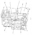
- Fig.7 illustrates the installation and operation principle of the overload protection device according to the present disclosure within the thermal magnetic adjustable trip unit 5.
- the overload protection device which comprises the first heating band 1, the bimetallic strip 3, the litzendraht wire 4, the second heating band 2, is installed in the base 5-1 of the thermal magnetic adjustable trip unit 5.
- the thermal magnetic adjustable trip unit is provided with overload protection and short-circuit protection functions, wherein the overload protection function of the thermal magnetic adjustable trip unit is achieved in a way as follows: with the overload current flowing through and heating the overload protection device, thereby deflecting the bimetallic strip 3 leftwards, the draft bar 5-2 is pushed to rotate counterclockwise so that the draft bar 5-2 and the tripping bar 5-3 move and release with respect to each other and, the tripping bar 5-3 occurs release and also causes the breaker body to release and cut off the overload current.
- the short-circuit protection function of the thermal magnetic adjustable trip unit is achieved in a way as follows: with the short-circuit current flowing through the overload protection device, a magnetic field occurs in the air gap enclosed by the static armature 5-4 and the moving armature 5-5 (the magnetic fields created by the currents flowing in inversed directions counteract with each other, thus it is required to have odd-numbered current loops in this area, as for the present disclosure, the numbers of current loop between the moving and static armatures are 3), and attractive force is created between the static armature 5-4 and the moving armature 5-5, thereby the moving armature rotates clockwise around the pivotal shaft 5-6 and pushes the draft bar 5-2 to rotate counterclockwise, tripping bar 5-3 then occurs release and causes the breaker body to release and thus cut off the short-circuit current.
- a breaker comprising the thermal magnetic adjustable trip unit as mentioned above is also provided.
- the current loop comprises the first heating band 1, the bimetallic strip 3, the litzendraht wire 4 and the second heating band 2, and comparing with the existing product, the length and the resistance value of the circuit loop according to the present disclosure is dramatically increased, thereby the temperature rising and deflection amount occurred for the bimetallic strip of the trip unit with a lower rated current is also dramatically increased, this design provides a more reliable overload protection function and much more easier thermal tuning and reduces the manufacturing cost.
- the second heating band Through selection of materials for the second heating band, the bimetallic strip, and the first heating band, it is possible to optimize the temperature rising distribution along the whole circuit loop, so that when the bimetallic strip has a higher temperature rising, the terminal and the breaker body would have a lower temperature rising (meet the standard requirements), thus increasing the design margin for the temperature rising of the breaker.
- the increasement of circuit impedance due to the increasement of circuit impedance, it is possible to restrict the short-circuit current more effectively and protect the whole circuit loop comprising the bimetallic strip also, meanwhile it is more conducive to the realization of breaking.
- the thermal tuning for the existing product is set to be 0.7 mm
- the thermal tuning provided by this novel configuration can be set to be about 2.5 mm
- a area between the regulated non-release curve and the regulated release curve is broadened by 3 times, thus the thermal tuning is easier to achieve and the reliability of overload protection is greatly improved.
Abstract
Description
- The present disclosure relates to an overload protection device, and particularly relates to an overload protection device applied to a thermal magnetic trip unit for a breaker.
- As for the present thermal magnetic trip unit with less rated current (for example, 15A, 16A, 20A etc.), the general problems thereof are lower temperature rising, minor deflection of a bimetallic strip, thus causing unreliable overload protection, that is, it is easy to occur late release or false release. When manufacturing such releasers, they are usually subjected to difficulties of industrialized thermal tuning and higher rework rate, thereby increasing the manufacturing cost. Furthermore, the massive short-circuit current is also readily to cause damage to the bimetallic strip when it is flowing through the bimetallic strip.
- For example, in the present directly-heated trip unit with lower rated current, the temperature rising of the bimetallic strip in a current loop mainly depends on the heat generated by the bimetallic strip per se, however, such heat output is low due to the limited length of the bimetallic strip, and further, and due to the fact that the bimetallic strip is connected to the client terminals directly through the litzendraht wire so that heat dissipation is rapid, the bimetallic strip thus has lower temperature-rising under a certain current and a minor deflection, its reliability for the overload protection is low and the thermal tuning is difficult, at the same time, the bimetallic strip is easy to be overheated and damaged under the short circuit.
- In order to overcome the above defects in prior art, the present disclosure provides an overload protection device, and particularly provides an overload protection device applied to a thermal magnetic trip unit of a breaker.
- According to one aspect of the present disclosure, an overload protection device is disclosed, characterised in that, the overload protection device comprises a first heating band; a second heating band; a bimetallic strip; a litzendraht wire; a lower part of the first heating band and a lower part of the bimetallic strip are mechanically connected with each other; two ends of the litzendraht wire mechanically connect with an upper part of the second heating band and an upper part of the bimetallic strip respectively.
- The mechanical connection of both ends of the litzendraht wire respectively with the upper parts of the first and second heating bands is accomplished by soldering.
- The mechanical connection of the lower parts of the first heating band and the bimetallic strip is accomplished by soldering.
- Current is flowing through the upper part of the first heating band, the lower part of the first heating band, the lower part of the bimetallic strip, the upper part of the bimetallic strip, the litzendraht wire, the upper part of the second heating band, and the lower part of the second heating band, thus forming an odd-numbered current loop.
- According to one aspect of the present disclosure, the first heating band and the second heating band are made from flat metal band being bent in a substantial L-shape.
- The litzendraht wire is bent in a substantial U-shape. Naturally, the skilled person in this art could bend the litzendraht wire in other shapes, as long as the shape of the bent litzendraht wire can constitute odd-numbered current loop within an air gap enclosed by a moving armature and a static armature (as described in the following).
- According to the present disclosure, there is also provided a thermal magnetic adjustable releaser, which comprises the overload protection device as described above, and further comprises a base, a draft bar, a tripping bar, the static armature, the moving armature and a pivotal shaft.
- The overload protection device according to the present disclosure is installed within the thermal magnetic adjustable releaser. The overload protection device, which comprises the first heating band, the bimetallic strip, the litzendraht wire, the second heating band, is installed in the base of the thermal magnetic adjustable releaser.
- The thermal magnetic adjustable trip unit is provided with overload protection and short-circuit protection functions, wherein the overload protection function of the thermal magnetic adjustable trip unit is achieved in a way as follows: with the overload current flowing through and heating the overload protection device, thereby deflecting the bimetallic strip leftwards, the draft bar is pushed to rotate counterclockwise so that the draft bar and the tripping bar move and release with respect to each other and, the tripping bar occurs release and also causes the break body to release and thus cut off the overload current. The short-circuit protection function of the thermal magnetic adjustable trip unit is achieved in a way as follows: with the short-circuit current flowing through the overload protection device, a magnetic field occurs in the air gap enclosed by the static armature and the moving armature (the magnetic fields created by the currents flowing in inversed directions counteracts with each other, thus it is required to have current loop for uneven times in this area, as for the present disclosure, the number of the current loop between the moving and static armatures is 3), and attractive force is created between the static armature and the moving armature, thereby the moving armature rotates clockwise around the pivotal shaft and pushes the draft bar to rotate counterclockwise, the tripping bar occurs release and causes the breaker body to release and thus cut off the short-circuit current.
- According to the present disclosure, an breaker comprising the thermal magnetic adjustable trip unit as mentioned above is also provided.
- In the overload protection device disclosed in the present disclosure, the new second heating band is added into circuit loop and is also connected to the bimetallic strip through the litzendraht wire, the bimetallic strip and the first heating band (also known as: terminal) are connected with each other, such that the length of the current loop is far longer than that in the existing product. In this way, the current loop in the trip unit comprises the first heating band, the bimetallic strip, the litzendraht wire and the second heating band, and the length and resistance value added into the circuit loop is dramatically increased when comparing with the existing product, thereby the temperature rising and deflection amount occurred for the bimetallic strip of the trip unit with lower rated current is also dramatically increased, and providing a more reliable overload protection function and much more easier industrialized thermal tuning and reducing manufacturing cost. Through selection of materials for the second heating band, the bimetallic strip, and the first heating band, it is possible to optimize the temperature rising distribution along the whole circuit, so that, when the bimetallic strip has a higher temperature rising, the terminal and the breaker body would have a lower temperature rising (meet the standard requirements), thus increasing the design margin for the temperature rising of the breaker. At the same time, due to the increasement of circuit impedance, it is possible to restrict the short-circuit current more effectively and protect the whole circuit loop comprising the bimetallic strip also, meanwhile it is more conducive to the realization of breaking.
- Simulation and experiment have proved that the current loop of this configuration causes an obviously improved deflection of the bimetallic strip than that of the existing product. The thermal tuning for the existing product is set to be 0.7 mm, the thermal tuning provided by this novel configuration can be set to be about 2.5 mm, and a area between the regulated non-release curve and the regulated release curve is broadened by 3 times, thus the thermal tuning is easier to achieve and the reliability of overload protection is greatly improved.
- So far, in order that the detailed description of the present disclosure can be better understood, and also in order that the contribution of the present disclosure to the prior art can be best recognized, the present disclosure has summarized the embodiments of present disclosure quite extensively. Of course, the embodiments of the present disclosure will be described in the following, and will establish the subject matter of the attached claims.
- Before explaining the embodiment of present disclosure in detail, it should be understood that the present disclosure is not restricted to the details of structure and configuration of the components and equivalent steps set out in the following description or illustrated in the drawings. The present disclosure can comprise embodiments other than the described ones, and can be embodied and carried out in different manners. Moreover, it should be appreciated that the wording and terminology and summary used herein are merely for descriptive purpose, and should not be construed as being restrictive.
- Likewise, the skilled person in this art would recognize that the technical conception on which the present disclosure is based may be readily used for the basis for designing other configurations, and be used to implement several purposes of the present disclosure. Hence, it is important that the attached claims should be considered as encompassing such equivalent structures, so long as they do not go beyond the essence and scope of the present disclosure.
- The following drawings would provide a better understanding of the present disclosure for the skilled person in this art, and could present the advantages of the present disclosure even more clearly. The drawings described herein are merely used for the purpose of describing the selected embodiments, rather than all of the possible embodiments, and do not intend to limit the scope of the present disclosure.
-
Fig.1 illustrates a first heating band according to the present disclosure; -
Fig.2 illustrates a second heating band according to the present disclosure; -
Fig.3 illustrates a bimetallic strip according to the present disclosure; -
Fig.4 illustrates a litzendraht wire according to the present disclosure; -
Fig.5 illustrates the assembly view of the overload protection device comprising the first heating band, the second heating band, the bimetallic strip and the litzendraht wire according to the present disclosure; -
Fig.6 illustrates a current circuit including the first heating band, the bimetallic strip, the litzendraht wire and the second heating band; -
Fig.7 illustrates a perspective view of the thermal magnetic adjustable trip unit which comprises the overload protection device ofFig.5 . - In the following, a detailed description will be made to the preferable embodiments according to the present disclosure in conjunction with the attached drawings. Based on the drawings and corresponding description, the skilled person in this art would comprehend the features and advantages of the present disclosure.
-
Fig.1 illustrates afirst heating band 1 according to the present disclosure, wherein thefirst heating band 1 comprises an upper part 1-1 of the first heating band and a lower part 1-2 of the first heating band, the first heating band is made from a flat metal band being bent in a substantial L-shape. -
Fig.2 illustrates asecond heating band 2 according to the present disclosure, wherein thesecond heating band 2 comprises an upper part 2-1 of the second heating band and a lower part 2-2 of the second heating band, and the second heating band is made from a flat metal band being bent in a substantial L-shape. -
Fig.3 illustrates abimetallic strip 3 according to the present disclosure, thebimetallic strip 3 comprises an upper part 3-1 of the bimetallic strip and a lower part 3-2 of the bimetallic strip. -
Fig.4 illustrates alitzendraht wire 4 according to the present disclosure, thelitzendraht wire 4 comprises two ends 4-1 and 4-2. -
Fig.5 shows an assembly view of the overload protection device according to the present disclosure comprising thefirst heating band 1, thesecond heating band 2, thebimetallic strip 3 and thelitzendraht wire 4, wherein the lower part of thefirst heating band 1 is mechanically connected with the lower part of thebimetallic strip 3; the two ends 4-1 and 4-2 of thelitzendraht wire 4 are mechanically connected with the upper parts of thesecond heating band 2 and thebimetallic strip 3 respectively. - The mechanical connection of both ends 4-1 and 4-2 of the
litzendraht wire 4 respectively with the upper parts of thesecond heating band 2 and thebimetallic strip 3 is accomplished by soldering. - The mechanical connection of the lower parts of the
first heating band 1 and thebimetallic strip 3 is accomplished by soldering. -
Fig.6 illustrates a current (circuit) loop comprising thefirst heating band 1, thebimetallic strip 3, thelitzendraht wire 4 and thesecond heating band 2, wherein the current flows through in order of the upper part 1-1 of thefirst heating band 1, the lower part 1-2 of thefirst heating band 1, the lower part 3-2 of thebimetallic strip 3, the upper part 3-1 of thebimetallic strip 3, thelitzendraht wire 4, the upper part 2-1 of thesecond heating band 2 and the lower part 2-2 of thesecond heating band 2 in a direction of an arrow successively, thereby forming an odd-numbered current loop. - As shown in
Fig.5 , thelitzendraht wire 4 is bent in a substantial U-shape. Naturally, the skilled person in this art could bend the litzendraht wire into other shapes, as long as the shape of the bent litzendraht wire can constitute the odd-numbered current loop within an air gap enclosed between a moving armature and a static armature. - According to the present disclosure, a thermal magnetic adjustable trip unit comprising the overload protection device as mentioned above is also provided.
- As shown in
Fig.7 , the present disclosure provides a thermal magnetic adjustable trip unit 5 comprising the overload protection device as shown inFig.5 , and furthing comprising a base 5-1, a draft bar 5-2, a tripping bar 5-3, the static armature 5-4, the moving armature 5-5 and a pivotal shaft 5-6. -
Fig.7 illustrates the installation and operation principle of the overload protection device according to the present disclosure within the thermal magnetic adjustable trip unit 5. The overload protection device, which comprises thefirst heating band 1, thebimetallic strip 3, thelitzendraht wire 4, thesecond heating band 2, is installed in the base 5-1 of the thermal magnetic adjustable trip unit 5. - The thermal magnetic adjustable trip unit is provided with overload protection and short-circuit protection functions, wherein the overload protection function of the thermal magnetic adjustable trip unit is achieved in a way as follows: with the overload current flowing through and heating the overload protection device, thereby deflecting the
bimetallic strip 3 leftwards, the draft bar 5-2 is pushed to rotate counterclockwise so that the draft bar 5-2 and the tripping bar 5-3 move and release with respect to each other and, the tripping bar 5-3 occurs release and also causes the breaker body to release and cut off the overload current. The short-circuit protection function of the thermal magnetic adjustable trip unit is achieved in a way as follows: with the short-circuit current flowing through the overload protection device, a magnetic field occurs in the air gap enclosed by the static armature 5-4 and the moving armature 5-5 (the magnetic fields created by the currents flowing in inversed directions counteract with each other, thus it is required to have odd-numbered current loops in this area, as for the present disclosure, the numbers of current loop between the moving and static armatures are 3), and attractive force is created between the static armature 5-4 and the moving armature 5-5, thereby the moving armature rotates clockwise around the pivotal shaft 5-6 and pushes the draft bar 5-2 to rotate counterclockwise, tripping bar 5-3 then occurs release and causes the breaker body to release and thus cut off the short-circuit current. - According to the present disclosure, a breaker comprising the thermal magnetic adjustable trip unit as mentioned above is also provided.
- In this current loop of the new trip unit designed according to the present disclosure, the current loop comprises the
first heating band 1, thebimetallic strip 3, thelitzendraht wire 4 and thesecond heating band 2, and comparing with the existing product, the length and the resistance value of the circuit loop according to the present disclosure is dramatically increased, thereby the temperature rising and deflection amount occurred for the bimetallic strip of the trip unit with a lower rated current is also dramatically increased, this design provides a more reliable overload protection function and much more easier thermal tuning and reduces the manufacturing cost. Through selection of materials for the second heating band, the bimetallic strip, and the first heating band, it is possible to optimize the temperature rising distribution along the whole circuit loop, so that when the bimetallic strip has a higher temperature rising, the terminal and the breaker body would have a lower temperature rising (meet the standard requirements), thus increasing the design margin for the temperature rising of the breaker. At the same time, due to the increasement of circuit impedance, it is possible to restrict the short-circuit current more effectively and protect the whole circuit loop comprising the bimetallic strip also, meanwhile it is more conducive to the realization of breaking. - Simulation and experiment have proved that the current loop based on this configuration causes an obviously improved deflection of the bimetallic strip than that of the existing product. The thermal tuning for the existing product is set to be 0.7 mm, the thermal tuning provided by this novel configuration can be set to be about 2.5 mm, and a area between the regulated non-release curve and the regulated release curve is broadened by 3 times, thus the thermal tuning is easier to achieve and the reliability of overload protection is greatly improved.
- Referring to the specific embodiments, although the present disclosure has already been described in the Description and the drawings, it should be appreciated that the skilled person in this art could make various alteration and various equivalent matter could substitute for the method steps and detection means therein without departing from the scope of the present disclosure defined by the attached claims. Furthermore, the combination and mating among the technical features, elements and/or functions of the specific embodiments herein is clear, thus according to the present disclosure, the skilled person in this art could appreciate that the technical features, elements and/or functions in these embodiments may be combined into another specific embodiment as required, unless the aforesaid contents being described otherwise. Moreover, according to the teaching of the present disclosure, many modifications may be done so as to adapt to special situation without departing from the essential scope of the present disclosure. Therefore, the present disclosure is not limited to individual specific embodiments illustrated in the drawings, and specific embodiments described as the optimal embodiments proposed for conducting the present disclosure in the Description, but the present disclosure intends to encompass all the embodiments fall into the scope of the Description and the attached claims.
Claims (11)
- An overload protection device, characterised in that the overload protection device comprises:a first heating band;a second heating band;a bimetallic strip;a litzendraht wire;a lower part of the first heating band is mechanically connected with a lower part of the bimetallic strip;two ends of the litzendraht wire mechanically connect with an upper part of the second heating band and an upper part of the bimetallic strip respectively.
- The overload protection device according to claim 1, characterised in that a mechanical connection of both ends of the litzendraht wire respectively with the upper parts of the first and second heating bands is accomplished by soldering.
- The overload protection device according to claim 1, characterised in that a mechanical connection of the lower parts of the first heating band and the bimetallic strip is accomplished by soldering.
- The overload protection device according to claim 1, characterised in that the first and second heating bands are made from flat metal band being bent in a substantial L-shape.
- The overload protection device according to claim 1, characterised in that current flows through the upper part of the first heating band, the lower part of the first heating band, the lower part of the bimetallic strip, the upper part of the bimetallic strip, the litzendraht wire, the upper part of the second heating band, and the lower part of the second heating band, thus forming an odd-numbered current loop.
- The overload protection device according to claim 1, characterised in that the litzendraht wire is bent in a substantial U-shape.
- A thermal magnetic adjustable releaser, characterised in that the thermal magnetic adjustable trip unit comprises an overload protection device according to any one of claims 1-6, and further comprises a base, a draft bar, a tripping bar, a static armature, a moving armature and a pivotal shaft.
- The thermal magnetic adjustable trip unit according to claim 7, characterised in that due to the overload current flowing through and heating the overload protection device, the bimetallic strip is deflected leftwards, the draft bar is pushed to rotate counterclockwise so that the draft bar and the tripping bar move and release with respect to each other, the tripping bar occurs release and also causes a breaker body to release and thus cut off the overload current.
- The thermal magnetic adjustable trip unit according to claim 7, characterised in that due to the short-circuit current flowing through the overload protection device, a magnetic field occurs in an air gap enclosed by the static armature and the moving armature, and attractive force is formed between the static armature and the moving armature, thereby the moving armature rotates clockwise around the pivotal shaft and pushes the draft bar to rotate counterclockwise, the tripping bar occurs release and causes the breaker body to release and thus cut off the short-circuit current.
- The thermal magnetic adjustable trip unit according to claim 9, characterised in that the number of the current loop between the static armature and the moving armature is odd.
- A breaker, characterised in that the breaker comprising the thermal magnetic adjustable trip unit according to any one of claims 7-10.
Applications Claiming Priority (2)
| Application Number | Priority Date | Filing Date | Title |
|---|---|---|---|
| CN201210585075.1A CN103903921B (en) | 2012-12-28 | 2012-12-28 | Overload protection arrangement and include the thermomagnetic adjustable release device of breaker of this device |
| PCT/CN2013/090573 WO2014101799A1 (en) | 2012-12-28 | 2013-12-26 | Overload protection device, and thermomagnetic adjustable release for breaker comprising same |
Publications (3)
| Publication Number | Publication Date |
|---|---|
| EP2930735A1 true EP2930735A1 (en) | 2015-10-14 |
| EP2930735A4 EP2930735A4 (en) | 2016-07-13 |
| EP2930735B1 EP2930735B1 (en) | 2019-05-08 |
Family
ID=50995189
Family Applications (1)
| Application Number | Title | Priority Date | Filing Date |
|---|---|---|---|
| EP13867090.6A Active EP2930735B1 (en) | 2012-12-28 | 2013-12-26 | Overload protection device, and thermomagnetic adjustable release for breaker comprising same |
Country Status (6)
| Country | Link |
|---|---|
| US (1) | US10074502B2 (en) |
| EP (1) | EP2930735B1 (en) |
| CN (1) | CN103903921B (en) |
| ES (1) | ES2735626T3 (en) |
| HU (1) | HUE045843T2 (en) |
| WO (1) | WO2014101799A1 (en) |
Families Citing this family (6)
| Publication number | Priority date | Publication date | Assignee | Title |
|---|---|---|---|---|
| CN105448613B (en) * | 2014-08-15 | 2019-05-07 | 施耐德电气工业公司 | Buckle releaser for breaker |
| US11476657B2 (en) * | 2020-07-09 | 2022-10-18 | Entrantech Inc. | DC power attachment device |
| US11605970B2 (en) | 2020-08-13 | 2023-03-14 | Entrantech Inc. | Persistent DC power and control switch |
| US11777323B2 (en) | 2020-08-13 | 2023-10-03 | Entrantech Inc. | Sequential power discharge for batteries in a power system |
| US11489455B2 (en) | 2020-08-13 | 2022-11-01 | Entrantech Inc. | AC and persistent DC co-distritbution |
| US11831167B2 (en) | 2021-08-13 | 2023-11-28 | Entrantech Inc. | Persistent Dc circuit breaker |
Family Cites Families (21)
| Publication number | Priority date | Publication date | Assignee | Title |
|---|---|---|---|---|
| NL257660A (en) * | 1960-01-07 | |||
| US4081852A (en) * | 1974-10-03 | 1978-03-28 | Westinghouse Electric Corporation | Ground fault circuit breaker |
| US4546336A (en) * | 1983-09-02 | 1985-10-08 | Eaton Corporation | Residential circuit breaker with combination slot motor and arc chute |
| DE3338799A1 (en) | 1983-10-26 | 1985-05-09 | Brown, Boveri & Cie Ag, 6800 Mannheim | Thermal trip device |
| SU1188803A1 (en) * | 1984-03-28 | 1985-10-30 | Kh Polt I Im V I Lenina | Combined-heating thermocouple unit for thermal releasing device |
| US4771254A (en) * | 1987-09-04 | 1988-09-13 | General Electric Company | Circuit breaker magnetic trip unit |
| GB2228829B (en) * | 1989-02-22 | 1992-11-25 | Crabtree Electrical Ind Ltd | Improvements relating to circuit breakers |
| FR2703823B1 (en) * | 1993-04-08 | 1995-05-12 | Merlin Gerin | Magneto-thermal trip module. |
| US5680081A (en) * | 1994-01-13 | 1997-10-21 | Square D Company | Circuit breaker having double break mechanism |
| US5831509A (en) * | 1997-10-22 | 1998-11-03 | Eaton Corporation | Circuit breaker with sense bar to sense current from voltage drop across bimetal |
| US6326869B1 (en) * | 1999-09-23 | 2001-12-04 | General Electric Company | Clapper armature system for a circuit breaker |
| US6515569B2 (en) * | 2000-12-18 | 2003-02-04 | Eaton Corporation | Circuit breaker with bypass conductor commutating current out of the bimetal during short circuit interruption and method of commutating current out of bimetal |
| DE102006003124A1 (en) * | 2006-01-23 | 2007-08-02 | Siemens Ag | Method for implementing an improved thermo-mechanical overload protection and associated overload protection device |
| US7518482B2 (en) * | 2006-10-10 | 2009-04-14 | Dennis William Fleege | Trip unit having a plurality of stacked bimetal elements |
| US7397333B2 (en) * | 2006-10-18 | 2008-07-08 | Square D Company | Trip unit having bimetal element located outside the yoke |
| CN100464387C (en) | 2006-12-15 | 2009-02-25 | 大全集团有限公司 | Break tripping device |
| AT509407A1 (en) * | 2008-03-05 | 2011-08-15 | Moeller Gebaeudeautomation Gmbh | SWITCHGEAR |
| KR101096988B1 (en) * | 2008-12-31 | 2011-12-20 | 엘에스산전 주식회사 | Trip device |
| CN101976640B (en) * | 2010-09-20 | 2012-11-21 | 江苏大全凯帆电器股份有限公司 | Low-voltage breaker tripper |
| DE102012202153B4 (en) * | 2012-02-14 | 2021-09-16 | Siemens Aktiengesellschaft | Thermomagnetic release for small current ranges as well as electrical switching device with it |
| CN203192722U (en) * | 2012-12-28 | 2013-09-11 | 施耐德电器工业公司 | Overload protection apparatus, thermomagnetic adjustability release, and circuit breaker |
-
2012
- 2012-12-28 CN CN201210585075.1A patent/CN103903921B/en active Active
-
2013
- 2013-12-26 EP EP13867090.6A patent/EP2930735B1/en active Active
- 2013-12-26 HU HUE13867090A patent/HUE045843T2/en unknown
- 2013-12-26 US US14/655,915 patent/US10074502B2/en active Active
- 2013-12-26 ES ES13867090T patent/ES2735626T3/en active Active
- 2013-12-26 WO PCT/CN2013/090573 patent/WO2014101799A1/en active Application Filing
Also Published As
| Publication number | Publication date |
|---|---|
| US10074502B2 (en) | 2018-09-11 |
| ES2735626T3 (en) | 2019-12-19 |
| US20150348733A1 (en) | 2015-12-03 |
| CN103903921B (en) | 2016-08-17 |
| EP2930735A4 (en) | 2016-07-13 |
| HUE045843T2 (en) | 2020-01-28 |
| CN103903921A (en) | 2014-07-02 |
| WO2014101799A1 (en) | 2014-07-03 |
| EP2930735B1 (en) | 2019-05-08 |
Similar Documents
| Publication | Publication Date | Title |
|---|---|---|
| EP2930735A1 (en) | Overload protection device, and thermomagnetic adjustable release for breaker comprising same | |
| US7518482B2 (en) | Trip unit having a plurality of stacked bimetal elements | |
| EP2261944B1 (en) | Circuit breaker | |
| EP2924704B1 (en) | Electromagnetic relay | |
| CN101976640B (en) | Low-voltage breaker tripper | |
| CN104867790B (en) | The method of the magnetic trigger device and overcurrent triggering device and electric switch of electric switch and the magnetic triggering for calibrating magnetic trigger device | |
| US5694101A (en) | Circuit breaker | |
| CN103608886B (en) | Motor protector | |
| US20160260567A1 (en) | Heater Apparatus, Circuit Interrupter, and Related Method | |
| EP1131836B1 (en) | Clapper armature system for a circuit breaker | |
| KR101647915B1 (en) | Circuit breaker | |
| EP2639812B1 (en) | Circuit protection device and trip unit for use with a circuit protection device | |
| US9406474B2 (en) | Circuit breaker heaters and translational magnetic systems | |
| DE102012202153B4 (en) | Thermomagnetic release for small current ranges as well as electrical switching device with it | |
| CN203192722U (en) | Overload protection apparatus, thermomagnetic adjustability release, and circuit breaker | |
| CN101359561B (en) | Release with step type yoke structure and circuit breaker with the release | |
| US6229413B1 (en) | Support of stationary conductors for a circuit breaker | |
| CN102315052A (en) | Electromagnetic tripping device for electric switchgear, electric switchgear comprising such a tripping device | |
| US2900473A (en) | Magnetic shield | |
| EP2830079A1 (en) | Bimetal unit, trip unit, circuit breaker, series of circuit breakers, and method for calibrating circuit breaker | |
| CN107154325B (en) | Overload alarm non-tripping device of circuit breaker | |
| CN215266156U (en) | Thermo-electromagnetic release | |
| CN214012876U (en) | Thermomagnetic release of moulded case circuit breaker | |
| CN217387042U (en) | Contact assembly for circuit breaker | |
| CN216647959U (en) | NTC thermistor |
Legal Events
| Date | Code | Title | Description |
|---|---|---|---|
| PUAI | Public reference made under article 153(3) epc to a published international application that has entered the european phase |
Free format text: ORIGINAL CODE: 0009012 |
|
| 17P | Request for examination filed |
Effective date: 20150626 |
|
| AK | Designated contracting states |
Kind code of ref document: A1 Designated state(s): AL AT BE BG CH CY CZ DE DK EE ES FI FR GB GR HR HU IE IS IT LI LT LU LV MC MK MT NL NO PL PT RO RS SE SI SK SM TR |
|
| AX | Request for extension of the european patent |
Extension state: BA ME |
|
| DAX | Request for extension of the european patent (deleted) | ||
| RA4 | Supplementary search report drawn up and despatched (corrected) |
Effective date: 20160614 |
|
| RIC1 | Information provided on ipc code assigned before grant |
Ipc: H01H 71/16 20060101AFI20160606BHEP Ipc: H01H 71/40 20060101ALI20160606BHEP |
|
| STAA | Information on the status of an ep patent application or granted ep patent |
Free format text: STATUS: REQUEST FOR EXAMINATION WAS MADE |
|
| STAA | Information on the status of an ep patent application or granted ep patent |
Free format text: STATUS: EXAMINATION IS IN PROGRESS |
|
| 17Q | First examination report despatched |
Effective date: 20180404 |
|
| GRAP | Despatch of communication of intention to grant a patent |
Free format text: ORIGINAL CODE: EPIDOSNIGR1 |
|
| STAA | Information on the status of an ep patent application or granted ep patent |
Free format text: STATUS: GRANT OF PATENT IS INTENDED |
|
| INTG | Intention to grant announced |
Effective date: 20181119 |
|
| GRAS | Grant fee paid |
Free format text: ORIGINAL CODE: EPIDOSNIGR3 |
|
| GRAA | (expected) grant |
Free format text: ORIGINAL CODE: 0009210 |
|
| STAA | Information on the status of an ep patent application or granted ep patent |
Free format text: STATUS: THE PATENT HAS BEEN GRANTED |
|
| AK | Designated contracting states |
Kind code of ref document: B1 Designated state(s): AL AT BE BG CH CY CZ DE DK EE ES FI FR GB GR HR HU IE IS IT LI LT LU LV MC MK MT NL NO PL PT RO RS SE SI SK SM TR |
|
| REG | Reference to a national code |
Ref country code: GB Ref legal event code: FG4D |
|
| REG | Reference to a national code |
Ref country code: CH Ref legal event code: EP Ref country code: AT Ref legal event code: REF Ref document number: 1131514 Country of ref document: AT Kind code of ref document: T Effective date: 20190515 |
|
| REG | Reference to a national code |
Ref country code: DE Ref legal event code: R096 Ref document number: 602013055260 Country of ref document: DE Ref country code: IE Ref legal event code: FG4D |
|
| REG | Reference to a national code |
Ref country code: SE Ref legal event code: TRGR |
|
| REG | Reference to a national code |
Ref country code: NL Ref legal event code: MP Effective date: 20190508 |
|
| REG | Reference to a national code |
Ref country code: LT Ref legal event code: MG4D |
|
| PG25 | Lapsed in a contracting state [announced via postgrant information from national office to epo] |
Ref country code: PT Free format text: LAPSE BECAUSE OF FAILURE TO SUBMIT A TRANSLATION OF THE DESCRIPTION OR TO PAY THE FEE WITHIN THE PRESCRIBED TIME-LIMIT Effective date: 20190908 Ref country code: LT Free format text: LAPSE BECAUSE OF FAILURE TO SUBMIT A TRANSLATION OF THE DESCRIPTION OR TO PAY THE FEE WITHIN THE PRESCRIBED TIME-LIMIT Effective date: 20190508 Ref country code: NL Free format text: LAPSE BECAUSE OF FAILURE TO SUBMIT A TRANSLATION OF THE DESCRIPTION OR TO PAY THE FEE WITHIN THE PRESCRIBED TIME-LIMIT Effective date: 20190508 Ref country code: NO Free format text: LAPSE BECAUSE OF FAILURE TO SUBMIT A TRANSLATION OF THE DESCRIPTION OR TO PAY THE FEE WITHIN THE PRESCRIBED TIME-LIMIT Effective date: 20190808 Ref country code: FI Free format text: LAPSE BECAUSE OF FAILURE TO SUBMIT A TRANSLATION OF THE DESCRIPTION OR TO PAY THE FEE WITHIN THE PRESCRIBED TIME-LIMIT Effective date: 20190508 Ref country code: HR Free format text: LAPSE BECAUSE OF FAILURE TO SUBMIT A TRANSLATION OF THE DESCRIPTION OR TO PAY THE FEE WITHIN THE PRESCRIBED TIME-LIMIT Effective date: 20190508 Ref country code: AL Free format text: LAPSE BECAUSE OF FAILURE TO SUBMIT A TRANSLATION OF THE DESCRIPTION OR TO PAY THE FEE WITHIN THE PRESCRIBED TIME-LIMIT Effective date: 20190508 |
|
| PG25 | Lapsed in a contracting state [announced via postgrant information from national office to epo] |
Ref country code: RS Free format text: LAPSE BECAUSE OF FAILURE TO SUBMIT A TRANSLATION OF THE DESCRIPTION OR TO PAY THE FEE WITHIN THE PRESCRIBED TIME-LIMIT Effective date: 20190508 Ref country code: LV Free format text: LAPSE BECAUSE OF FAILURE TO SUBMIT A TRANSLATION OF THE DESCRIPTION OR TO PAY THE FEE WITHIN THE PRESCRIBED TIME-LIMIT Effective date: 20190508 Ref country code: GR Free format text: LAPSE BECAUSE OF FAILURE TO SUBMIT A TRANSLATION OF THE DESCRIPTION OR TO PAY THE FEE WITHIN THE PRESCRIBED TIME-LIMIT Effective date: 20190809 Ref country code: BG Free format text: LAPSE BECAUSE OF FAILURE TO SUBMIT A TRANSLATION OF THE DESCRIPTION OR TO PAY THE FEE WITHIN THE PRESCRIBED TIME-LIMIT Effective date: 20190808 |
|
| REG | Reference to a national code |
Ref country code: AT Ref legal event code: MK05 Ref document number: 1131514 Country of ref document: AT Kind code of ref document: T Effective date: 20190508 |
|
| REG | Reference to a national code |
Ref country code: ES Ref legal event code: FG2A Ref document number: 2735626 Country of ref document: ES Kind code of ref document: T3 Effective date: 20191219 |
|
| REG | Reference to a national code |
Ref country code: HU Ref legal event code: AG4A Ref document number: E045843 Country of ref document: HU |
|
| PG25 | Lapsed in a contracting state [announced via postgrant information from national office to epo] |
Ref country code: AT Free format text: LAPSE BECAUSE OF FAILURE TO SUBMIT A TRANSLATION OF THE DESCRIPTION OR TO PAY THE FEE WITHIN THE PRESCRIBED TIME-LIMIT Effective date: 20190508 Ref country code: CZ Free format text: LAPSE BECAUSE OF FAILURE TO SUBMIT A TRANSLATION OF THE DESCRIPTION OR TO PAY THE FEE WITHIN THE PRESCRIBED TIME-LIMIT Effective date: 20190508 Ref country code: SK Free format text: LAPSE BECAUSE OF FAILURE TO SUBMIT A TRANSLATION OF THE DESCRIPTION OR TO PAY THE FEE WITHIN THE PRESCRIBED TIME-LIMIT Effective date: 20190508 Ref country code: RO Free format text: LAPSE BECAUSE OF FAILURE TO SUBMIT A TRANSLATION OF THE DESCRIPTION OR TO PAY THE FEE WITHIN THE PRESCRIBED TIME-LIMIT Effective date: 20190508 Ref country code: EE Free format text: LAPSE BECAUSE OF FAILURE TO SUBMIT A TRANSLATION OF THE DESCRIPTION OR TO PAY THE FEE WITHIN THE PRESCRIBED TIME-LIMIT Effective date: 20190508 Ref country code: DK Free format text: LAPSE BECAUSE OF FAILURE TO SUBMIT A TRANSLATION OF THE DESCRIPTION OR TO PAY THE FEE WITHIN THE PRESCRIBED TIME-LIMIT Effective date: 20190508 |
|
| REG | Reference to a national code |
Ref country code: DE Ref legal event code: R097 Ref document number: 602013055260 Country of ref document: DE |
|
| PG25 | Lapsed in a contracting state [announced via postgrant information from national office to epo] |
Ref country code: IT Free format text: LAPSE BECAUSE OF FAILURE TO SUBMIT A TRANSLATION OF THE DESCRIPTION OR TO PAY THE FEE WITHIN THE PRESCRIBED TIME-LIMIT Effective date: 20190508 Ref country code: SM Free format text: LAPSE BECAUSE OF FAILURE TO SUBMIT A TRANSLATION OF THE DESCRIPTION OR TO PAY THE FEE WITHIN THE PRESCRIBED TIME-LIMIT Effective date: 20190508 |
|
| PLBE | No opposition filed within time limit |
Free format text: ORIGINAL CODE: 0009261 |
|
| STAA | Information on the status of an ep patent application or granted ep patent |
Free format text: STATUS: NO OPPOSITION FILED WITHIN TIME LIMIT |
|
| PG25 | Lapsed in a contracting state [announced via postgrant information from national office to epo] |
Ref country code: TR Free format text: LAPSE BECAUSE OF FAILURE TO SUBMIT A TRANSLATION OF THE DESCRIPTION OR TO PAY THE FEE WITHIN THE PRESCRIBED TIME-LIMIT Effective date: 20190508 |
|
| 26N | No opposition filed |
Effective date: 20200211 |
|
| PG25 | Lapsed in a contracting state [announced via postgrant information from national office to epo] |
Ref country code: PL Free format text: LAPSE BECAUSE OF FAILURE TO SUBMIT A TRANSLATION OF THE DESCRIPTION OR TO PAY THE FEE WITHIN THE PRESCRIBED TIME-LIMIT Effective date: 20190508 |
|
| PG25 | Lapsed in a contracting state [announced via postgrant information from national office to epo] |
Ref country code: SI Free format text: LAPSE BECAUSE OF FAILURE TO SUBMIT A TRANSLATION OF THE DESCRIPTION OR TO PAY THE FEE WITHIN THE PRESCRIBED TIME-LIMIT Effective date: 20190508 |
|
| REG | Reference to a national code |
Ref country code: DE Ref legal event code: R119 Ref document number: 602013055260 Country of ref document: DE |
|
| REG | Reference to a national code |
Ref country code: CH Ref legal event code: PL |
|
| REG | Reference to a national code |
Ref country code: BE Ref legal event code: MM Effective date: 20191231 |
|
| PG25 | Lapsed in a contracting state [announced via postgrant information from national office to epo] |
Ref country code: MC Free format text: LAPSE BECAUSE OF FAILURE TO SUBMIT A TRANSLATION OF THE DESCRIPTION OR TO PAY THE FEE WITHIN THE PRESCRIBED TIME-LIMIT Effective date: 20190508 |
|
| GBPC | Gb: european patent ceased through non-payment of renewal fee |
Effective date: 20191226 |
|
| PG25 | Lapsed in a contracting state [announced via postgrant information from national office to epo] |
Ref country code: GB Free format text: LAPSE BECAUSE OF NON-PAYMENT OF DUE FEES Effective date: 20191226 Ref country code: IE Free format text: LAPSE BECAUSE OF NON-PAYMENT OF DUE FEES Effective date: 20191226 Ref country code: LU Free format text: LAPSE BECAUSE OF NON-PAYMENT OF DUE FEES Effective date: 20191226 Ref country code: DE Free format text: LAPSE BECAUSE OF NON-PAYMENT OF DUE FEES Effective date: 20200701 |
|
| PG25 | Lapsed in a contracting state [announced via postgrant information from national office to epo] |
Ref country code: BE Free format text: LAPSE BECAUSE OF NON-PAYMENT OF DUE FEES Effective date: 20191231 Ref country code: LI Free format text: LAPSE BECAUSE OF NON-PAYMENT OF DUE FEES Effective date: 20191231 Ref country code: CH Free format text: LAPSE BECAUSE OF NON-PAYMENT OF DUE FEES Effective date: 20191231 |
|
| PG25 | Lapsed in a contracting state [announced via postgrant information from national office to epo] |
Ref country code: CY Free format text: LAPSE BECAUSE OF FAILURE TO SUBMIT A TRANSLATION OF THE DESCRIPTION OR TO PAY THE FEE WITHIN THE PRESCRIBED TIME-LIMIT Effective date: 20190508 |
|
| PG25 | Lapsed in a contracting state [announced via postgrant information from national office to epo] |
Ref country code: IS Free format text: LAPSE BECAUSE OF FAILURE TO SUBMIT A TRANSLATION OF THE DESCRIPTION OR TO PAY THE FEE WITHIN THE PRESCRIBED TIME-LIMIT Effective date: 20190908 |
|
| PG25 | Lapsed in a contracting state [announced via postgrant information from national office to epo] |
Ref country code: MT Free format text: LAPSE BECAUSE OF FAILURE TO SUBMIT A TRANSLATION OF THE DESCRIPTION OR TO PAY THE FEE WITHIN THE PRESCRIBED TIME-LIMIT Effective date: 20190508 |
|
| PG25 | Lapsed in a contracting state [announced via postgrant information from national office to epo] |
Ref country code: MK Free format text: LAPSE BECAUSE OF FAILURE TO SUBMIT A TRANSLATION OF THE DESCRIPTION OR TO PAY THE FEE WITHIN THE PRESCRIBED TIME-LIMIT Effective date: 20190508 |
|
| PGFP | Annual fee paid to national office [announced via postgrant information from national office to epo] |
Ref country code: ES Payment date: 20230105 Year of fee payment: 10 |
|
| PGFP | Annual fee paid to national office [announced via postgrant information from national office to epo] |
Ref country code: SE Payment date: 20231218 Year of fee payment: 11 Ref country code: HU Payment date: 20231130 Year of fee payment: 11 Ref country code: FR Payment date: 20231220 Year of fee payment: 11 |