EP2930600B1 - Electronic device and information display program - Google Patents
Electronic device and information display program Download PDFInfo
- Publication number
- EP2930600B1 EP2930600B1 EP15161564.8A EP15161564A EP2930600B1 EP 2930600 B1 EP2930600 B1 EP 2930600B1 EP 15161564 A EP15161564 A EP 15161564A EP 2930600 B1 EP2930600 B1 EP 2930600B1
- Authority
- EP
- European Patent Office
- Prior art keywords
- magnified view
- view window
- target area
- size
- display
- Prior art date
- Legal status (The legal status is an assumption and is not a legal conclusion. Google has not performed a legal analysis and makes no representation as to the accuracy of the status listed.)
- Not-in-force
Links
Images


Classifications
-
- G—PHYSICS
- G06—COMPUTING OR CALCULATING; COUNTING
- G06F—ELECTRIC DIGITAL DATA PROCESSING
- G06F3/00—Input arrangements for transferring data to be processed into a form capable of being handled by the computer; Output arrangements for transferring data from processing unit to output unit, e.g. interface arrangements
- G06F3/01—Input arrangements or combined input and output arrangements for interaction between user and computer
- G06F3/048—Interaction techniques based on graphical user interfaces [GUI]
- G06F3/0484—Interaction techniques based on graphical user interfaces [GUI] for the control of specific functions or operations, e.g. selecting or manipulating an object, an image or a displayed text element, setting a parameter value or selecting a range
- G06F3/04845—Interaction techniques based on graphical user interfaces [GUI] for the control of specific functions or operations, e.g. selecting or manipulating an object, an image or a displayed text element, setting a parameter value or selecting a range for image manipulation, e.g. dragging, rotation, expansion or change of colour
-
- G—PHYSICS
- G06—COMPUTING OR CALCULATING; COUNTING
- G06F—ELECTRIC DIGITAL DATA PROCESSING
- G06F3/00—Input arrangements for transferring data to be processed into a form capable of being handled by the computer; Output arrangements for transferring data from processing unit to output unit, e.g. interface arrangements
- G06F3/01—Input arrangements or combined input and output arrangements for interaction between user and computer
- G06F3/048—Interaction techniques based on graphical user interfaces [GUI]
- G06F3/0481—Interaction techniques based on graphical user interfaces [GUI] based on specific properties of the displayed interaction object or a metaphor-based environment, e.g. interaction with desktop elements like windows or icons, or assisted by a cursor's changing behaviour or appearance
-
- G—PHYSICS
- G06—COMPUTING OR CALCULATING; COUNTING
- G06F—ELECTRIC DIGITAL DATA PROCESSING
- G06F3/00—Input arrangements for transferring data to be processed into a form capable of being handled by the computer; Output arrangements for transferring data from processing unit to output unit, e.g. interface arrangements
- G06F3/01—Input arrangements or combined input and output arrangements for interaction between user and computer
- G06F3/048—Interaction techniques based on graphical user interfaces [GUI]
- G06F3/0487—Interaction techniques based on graphical user interfaces [GUI] using specific features provided by the input device, e.g. functions controlled by the rotation of a mouse with dual sensing arrangements, or of the nature of the input device, e.g. tap gestures based on pressure sensed by a digitiser
- G06F3/0488—Interaction techniques based on graphical user interfaces [GUI] using specific features provided by the input device, e.g. functions controlled by the rotation of a mouse with dual sensing arrangements, or of the nature of the input device, e.g. tap gestures based on pressure sensed by a digitiser using a touch-screen or digitiser, e.g. input of commands through traced gestures
-
- G—PHYSICS
- G06—COMPUTING OR CALCULATING; COUNTING
- G06F—ELECTRIC DIGITAL DATA PROCESSING
- G06F3/00—Input arrangements for transferring data to be processed into a form capable of being handled by the computer; Output arrangements for transferring data from processing unit to output unit, e.g. interface arrangements
- G06F3/01—Input arrangements or combined input and output arrangements for interaction between user and computer
- G06F3/048—Interaction techniques based on graphical user interfaces [GUI]
- G06F3/0487—Interaction techniques based on graphical user interfaces [GUI] using specific features provided by the input device, e.g. functions controlled by the rotation of a mouse with dual sensing arrangements, or of the nature of the input device, e.g. tap gestures based on pressure sensed by a digitiser
- G06F3/0488—Interaction techniques based on graphical user interfaces [GUI] using specific features provided by the input device, e.g. functions controlled by the rotation of a mouse with dual sensing arrangements, or of the nature of the input device, e.g. tap gestures based on pressure sensed by a digitiser using a touch-screen or digitiser, e.g. input of commands through traced gestures
- G06F3/04883—Interaction techniques based on graphical user interfaces [GUI] using specific features provided by the input device, e.g. functions controlled by the rotation of a mouse with dual sensing arrangements, or of the nature of the input device, e.g. tap gestures based on pressure sensed by a digitiser using a touch-screen or digitiser, e.g. input of commands through traced gestures for inputting data by handwriting, e.g. gesture or text
-
- G—PHYSICS
- G06—COMPUTING OR CALCULATING; COUNTING
- G06T—IMAGE DATA PROCESSING OR GENERATION, IN GENERAL
- G06T3/00—Geometric image transformations in the plane of the image
- G06T3/40—Scaling of whole images or parts thereof, e.g. expanding or contracting
-
- G—PHYSICS
- G06—COMPUTING OR CALCULATING; COUNTING
- G06F—ELECTRIC DIGITAL DATA PROCESSING
- G06F2203/00—Indexing scheme relating to G06F3/00 - G06F3/048
- G06F2203/048—Indexing scheme relating to G06F3/048
- G06F2203/04805—Virtual magnifying lens, i.e. window or frame movable on top of displayed information to enlarge it for better reading or selection
-
- G—PHYSICS
- G06—COMPUTING OR CALCULATING; COUNTING
- G06F—ELECTRIC DIGITAL DATA PROCESSING
- G06F2203/00—Indexing scheme relating to G06F3/00 - G06F3/048
- G06F2203/048—Indexing scheme relating to G06F3/048
- G06F2203/04806—Zoom, i.e. interaction techniques or interactors for controlling the zooming operation
-
- G—PHYSICS
- G06—COMPUTING OR CALCULATING; COUNTING
- G06T—IMAGE DATA PROCESSING OR GENERATION, IN GENERAL
- G06T2200/00—Indexing scheme for image data processing or generation, in general
- G06T2200/24—Indexing scheme for image data processing or generation, in general involving graphical user interfaces [GUIs]
Definitions
- the embodiments discussed herein are related to an electronic device and an information display program.
- touch panel type electronic devices have spread, which may execute a variety of operations by a touch input onto a panel.
- a variety of touch panel type electronic devices are exemplified such as a mobile phone terminal, a smartphone, a tablet terminal, an e-book terminal and a personal computer (PC).
- One of the operations on the panel is an operation of selecting characters contained in a displayed image.
- the characters are hard to be selected due to the characters being small, and a selected portion is hard to be recognized because of being hidden under a finger as the case may be.
- Patent document 1 a technology (refer to, e.g., Patent document 1) is known, which displays the selected portion in magnification in another area.
- Patent document 1 Japanese National Publication of International Patent Application No. 2012-521048
- US 2011/0289462 discloses computing device magnification gesture techniques, in particular a magnifying window (a virtual loupe) defined with a gesture of two fingers.
- the gesture is defined by two touch points moving away from each other.
- the virtual loupe is placed such that the portion of user interface corresponding to the two initial points is magnified and the size of the virtual loupe is determined by the motion of the fingers while moving away.
- the centre of the virtual loupe as defined does not move while the loupe is displayed.
- the loupe could be placed at an offset position to leave the magnified portion unobscured.
- a magnified view window (which will hereinafter be also referred to as a magnifying glass) for displaying the selected portion in magnification has hitherto been difficult to confirm the whole selected portion by looking down upon the selected portion because of a size being fixed and being moved with a movement of a finger.
- One aspect of the present invention aims at providing an electronic device and an information display program, which can display a broader display target area in a magnified view window.
- Another aspect of the embodiments can encompass an information display program to make a computer function as the electronic device described above, and a non-transitory computer readable recording medium on which the program is recorded.
- the recording medium readable by the computer etc. connotes a recording medium that can store information such as data and programs electrically, magnetically, optically, mechanically or by chemical action, which can be read from the computer etc.
- the Example 1 is such an example that an electronic device magnifies and displays an area covering a touch position on a magnifying glass, and a size of the magnifying glass is enlarged corresponding to a movement of the touch position.
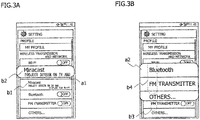
- FIGS. 3A through 3C are diagrams each illustrating a display example of the magnifying glass during an operation to select a setting menu screen.
- FIGS. 3A through 3C respectively depict the examples of the setting menu screen of a smartphone.
- FIG. 3A depicts a state after touching a letter "M” of "Miracast” as one of menu items.
- a symbol “a1” indicates the magnifying glass displayed on the setting menu screen.
- a portion encircled by a dotted line of "b1” represents a position touched by a user.
- a portion encircled by a dotted line of "b2” represents a portion corresponding to the touched position indicated by "b1" in a magnifying glass a1.
- the electronic device may display a marker like an image of a highlighter pen to facilitate recognition of the touched position, the maker being formed as, e.g., a frame of the dotted line of each of "b1" and "b2".
- the portions encircled by the dotted lines of "b1" and “b2" may be displayed in a different background color from that of a peripheral area.
- the magnifying glass a1 is displayed on the upper side of a portion encircled by the dotted line of "b1".
- the characters "Miracast” containing the touched position indicated by "b1" and a peripheral area thereof are magnified and displayed on the magnifying glass a1.
- FIG. 3B illustrates a state after a finger moving to downward to a menu item "Others” with the finger not being taken off from the state of touching the letter “M” of “Miracast” in FIG. 3A .
- a symbol “a2" indicates the magnifying glass displayed on a setting menu screen.
- a portion encircled by a dotted line of "b3” depicts a trajectory of the finger when moving downward to the menu item "Others” with the finger not being taken off from the state of touching the letter “M” of "Miracast”.
- a portion encircled by a dotted line of "b4" indicates a portion corresponding to the finger's trajectory indicated by "b3" in the magnifying glass a2.
- the electronic device may also display the marker like the image of the highlighter pen, the marker being formed as the frame of the dotted line of each of "b3" and "b4", to facilitate the recognition of the trajectory traced by the finger.
- the portions encircled by the dotted lines of "b3" and "b4" may be displayed in the different background color from that of the peripheral area.
- a view of the magnifying glass a2 is enlarged downward to an upper area of the position of the finger after being moved. The position of the finger after being moved and the upper area thereof are magnified and displayed on the magnifying glass a2.
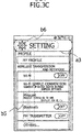
- FIG. 3C illustrates a state after the finger moving upward to characters "Setting” as a menu title with the finger not being taken off subsequent to the downward movement to the menu item “Others” in FIG. 3B .
- a symbol “a3" represents a magnifying glass displayed on the setting menu screen.
- a portion encircled by a dotted line of "b5" represents a trajectory of the finger when moving upward to the characters “Setting” as the menu title with the finger not being taken off through the state in FIG. 3B from the state in FIG. 3A .
- a portion encircled by a dotted line of "b6” represents a portion corresponding to the finger's trajectory on the screen of the smartphone in the magnifying glass a3.
- the finger' s trajectory corresponding to the portion encircled by the dotted line of "b6" is not depicted because of being positioned under the magnifying glass a3.
- the characters "Setting” and the peripheral area thereof are magnified and displayed on the magnifying glass a3.
- the electronic device may display the marker like the image of the highlighter pen to facilitate the recognition of the trajectory traced by the finger, the maker being formed as, e.g., the frame of the dotted line of each of "b5" and “b6".
- the portions encircled by the dotted lines of "b5" and "b6” may be displayed in the different background color from that of the peripheral area.
- FIG. 3C when the finger moves upward, it is taken into consideration that a text is read normally downward, and the electronic device does not enlarge the size of the magnifying glass upward from the touched position before the movement. However, the electronic device may enlarge the size of the magnifying glass depending on a content displayed on the screen even when the finger moves upward.
- FIGS. 3A through 3C depict the examples in which a size of horizontal width of the magnifying glass is fixed, however, the size of horizontal width of the magnifying glass in FIG. 3A may be enlarged from a smaller size than a size of horizontal width of the screen to the size of horizontal width of the screen. In other words, the size of horizontal width of the magnifying glass does not need to be fixed in the Example 1.
- FIG. 4A is a diagram illustrating an example of displaying the magnifying glass at an uppermost portion of the screen.
- FIG. 4A depicts a state in which a position between "FINE” and “WEATHER” of a sentence "IT IS A FINE WEATHER TODAY. " is touched by the finger.
- the magnifying glass is displayed on the upper side of the touched position, and the characters anterior and posterior to the touched position are magnified and displayed on the magnifying glass.
- FIG. 4B is a diagram illustrating such an example that the magnifying glass is overlaid on selected characters, the view being given at the uppermost portion of the screen.
- FIG. 4B similarly to FIG.
- FIG. 4A depicts the state in which the position between "FINE” and "WEATHER” of the sentence "IT IS A FINE WEATHER TODAY.” is touched by the finger.
- the sentence "IT IS A FINE WEATHER TODAY.” is, however, displayed in a position near the uppermost portion of the screen.
- the magnifying glass is so displayed as to be overlaid on the selected characters because of being unable to get space for displaying on the upper side of the touched position.
- the magnifying glass when moving up to the uppermost portion of the screen, without further moving or disappearing, is displayed at the uppermost portion of the screen in a state of keeping a predetermined size.
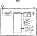
- FIG. 1 is a diagram illustrating one example of a hardware configuration of an electronic device 1.
- the electronic device 1 includes a processor 2, a storage unit 3, a touch sensor unit 4, a display unit 5, a wireless unit 6 and an audio Input/Output (I/O) unit 7.
- I/O audio Input/Output
- the processor 2 is, e.g., a CPU (Central Processing Unit) or a DSP (Digital Signal Processor).
- the storage unit 3 includes a ROM (Read Only Memory) 31 and a RAM (Random Access Memory) 32.
- the ROM 31 is a memory in which to store a variety of computer programs and data used by the processor 2 when executing the respective computer programs.
- the RAM 32 includes both of a volatile memory and a nonvolatile memory.
- the RAM 32 provides the processor 2 with a storage area for loading the computer program stored in the ROM 31 and an operation area. Further, the RAM 32 is used as a buffer for temporarily retaining the data.
- the touch sensor unit 4 is one of position input devices and acquires, when detecting that the display unit 5 is touched, a coordinate of the touched position of the finger on the screen and outputs the acquired coordinate to the processor 2.
- the touch sensor unit 4 may be of any of a resistance film type, a surface acoustic wave type, an infrared-ray type, an electromagnetic induction type, an electrostatic capacity type, etc.
- the display unit 5 is, e.g., a liquid crystal display (LCD).
- the display unit 5 displays screen data according to a signal inputted from the processor 2.
- the wireless unit 6 converts a radio signal received via an antenna into an electric signal and outputs the electric signal to the processor 2, or converts the electric signal inputted from the processor 2 into the radio signal and transmits the radio signal via the antenna.
- the wireless unit 6 is an electronic circuit that supports, e.g., the 3G (third-generation) mobile communication system.
- the audio I/O unit 7 converts an audio signal inputted from an audio input device such as a microphone into the electric signal and outputs the electric signal to the processor 2, or converts the electric signal inputted from the processor 2 into the audio signal and outputs the audio signal to an audio output device such as a speaker.
- the hardware configuration of the electronic device 1 may be, without being limited to the configuration illustrated in FIG. 1 , properly modified such as addition, replacement and deletion.
- the electronic device 1 is exemplified by a mobile phone terminal, a smartphone, a tablet terminal, an e-book terminal and a PC.
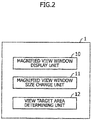
- FIG. 2 is a diagram illustrating one example of function blocks of the electronic device 1.
- the electronic device 1 includes, as the function blocks, a magnified view window display unit 10, a magnified view window size change unit 11 and a view target area determining unit 12.
- the processor 2 executes the computer programs deployed in an executable manner on the storage unit 3 as the magnified view window display unit 10, the magnified view window size change unit 11 and the view target area determining unit 12.
- hardware circuits may execute any one of the magnified view window display unit 10, the magnified view window size change unit 11 and the view target area determining unit 12, or a part of processes of these units.
- the magnified view window display unit 10 detects that the display unit 5 is touched and display the magnifying glass on the upper side of the touched position.
- the horizontal width of the magnifying glass maybe the same as a size of width of the display unit 5 and may also be smaller than the size of width of the display unit 5.
- a vertical width of the magnifying glass may be a predetermined size being set beforehand as an initial value.
- the magnified view window display unit 10 magnifies and displays contents of the areas anterior and posterior to the touched position on the magnifying glass. Note that when unable to get space for displaying the magnifying glass on the upper side of the touched position, the electronic device 1 may display the magnifying glass so as to be overlaid on the touched position.
- the magnified view window size change unit 11 detects a movement of the touched position and changes the size of the magnifying glass.
- the magnified view window size change unit 12 may enlarge the horizontal width of the magnifying glass up to the size of horizontal width of the screen.
- the magnified view window size change unit 11 may display, without enlarging the size of the magnifying glass, the magnifying glass including the post-moving touched position with the vertical width being the initial value.
- the view target area determining unit 12 determines a display target area including the post-moving touched position corresponding to the size of the magnifying glass, and displays the determined area on a magnified view window.
- the view target area determining unit 12 may also determine, as the display target area, an area of a range that includes the post-moving touched position and that can be displayed in the magnifying glass.
- the pre-moving touched position is one example of a first touched position.
- the post-moving touched position is one example of a second touched position.
- the touched position after the finger moves upward with the finger not being taken off subsequent to the downward movement as illustrated in FIG. 3C is one example of a third position.
- FIG. 7 is a diagram illustrating one example of calculating a display position and a display size of the magnifying glass of the electronic device 1.
- a left upward coordinate of the screen of the electronic device 1 is (0, 0).
- a right side in a horizontal direction (an X-axis direction) and a lower side in a vertical direction (a Y-axis direction) are positive sides.
- a touch panel is notified of a coordinate (x, y) of the touched position of the finger.
- the position in which the finger touches the screen of the electronic device 1 is indicated by a coordinate (x1, y1).
- a symbol "a” represents a size of horizontal width of the magnifying glass
- "b” designates an initial value of a size of vertical width of the magnifying glass
- "c” denotes a distance from a lower edge of the magnifying glass to the finger.
- the horizontal width of the magnifying glass is to be a width of the screen.
- FIG. 8 is a diagram illustrating one example of a flowchart of processes when detecting a touch event.
- the touch event occurs when detecting a touch operation on the screen of the electronic device 1.
- the touch event includes, e.g., a "down" event occurring when the finger touches the screen, a "move” event occurring when the touch finger moves, and an "up” event occurring when the finger takes off the screen.
- a start of the processes when detecting the touch event is triggered by, e.g., touching the display unit 5 of the electronic device 1 and the magnifying glass being displayed by the magnified view window display unit 10.
- the electronic device 1 detects that the display unit 5 is touched by the finger, and the processing is shifted to S02.
- the electronic device 1 stores the coordinate (x1, y1) of the touched position as a coordinate of an origin in the storage unit 3, and the processing is shifted to S03.
- the electronic device 1 detects the touch event and stores, in the storage unit 3, a coordinate (x, y) of the touched position when the touch event occurs, and the processing is shifted to S04.
- the electronic device 1 determines whether the detected touch event is the "move” event, and the processing is shifted to S05 when being the "move” event but is diverted to S08 whereas when not being the "move” event.
- the electronic device 1 compares a Y-coordinate "y1" of the origin with a Y-coordinate "y” of the post-moving position of the finger, and the processing is shifted to S06 when "y1 > y" but is diverted to S07 whereas when "y1 ⁇ y".
- the process in S06 is a process in case of "y1 > y", i.e., when the finger moves upward from the touched origin.
- the electronic device 1 sets a size of the magnified view window to a size of an area defined by a left upward coordinate (0, y-b-c) and a right downward coordinate (x3, y-c) by the magnified view window size change unit 11.
- the electronic device 1 magnifies and displays the determined display target area on the magnifying glass by the view target area determining unit 12.
- the process in S07 is a process in case of "y1 ⁇ y", i.e., when the finger moves downward from the touched origin.
- the electronic device 1 sets the size of the magnified view window to a size of an area defined by a left upward coordinate (x2, y2) and a right downward coordinate (x3, y-c) by the magnified view window size change unit 11.
- the electronic device 1 magnifies and displays the determined display target area on the magnifying glass by the view target area determining unit 12. After the magnifying glass is displayed in S06 or S07, the electronic device 1 loops the processing back to S03.
- the process in S08 is a process when the event is determined not to be the "move” event in S04.
- the electronic device 1 determines whether the detected touch event is the "up” event, and the processing is shifted to S09 when being the "up” event but is looped back to S03 whereas when not being the "up” event.
- the electronic device 1 hides the magnifying glass, resulting in finishing the processes when detecting the touch event.
- the electronic device 1 executes the processes in S06 and S07 as one example of enlarging a size of a magnified view window.
- the electronic device 1 according to Example 1 dynamically enlarges the size of the magnifying glass corresponding to the movement of the touched position. Therefore, not only the area with the fixed size including the touched position but also the broader area including the post-moving touched position, are displayed as the display target area on the magnifying glass having the enlarged size. Accordingly, this view facilitates looking down upon the broader area including the touched position. Further, the electronic device 1 can display the magnifying glass over also the menu screen etc. not based on a premise of editing in addition to the images based on the premise of editing such as copying and pasting. Hence, when hard to recognize a selected portion concealed by the finger due to the characters being small also on the menu screen etc. not based on the premise of editing, it is feasible to easily confirm the area including the touched position.
- FIG. 5A is a diagram illustrating a display example of the magnifying glass before the finger touching the screen moves downward.
- FIG. 5A depicts a state in which the finger moves rightward to between "FINE” and "WEATHER” after touching a left edge of a sentence "IT IS A FINE WEATHER TODAY. ".
- the horizontal width of the magnifying glass is the same of the horizontal width of the screen.
- FIG. 5B is a diagram illustrating a display example of the magnifying glass after the finger touching the screen moves downward. Specifically, FIG.
- FIG. 5B depicts a state in which the finger moves downward to "BE” in the sentence "IT WILL BE RAINY TOMORROW. " provided two lines below after the state in FIG. 5A . At this time, the size of the magnifying glass is enlarged downward, while the size of the horizontal width of the magnifying glass remains fixed.
- Example 2 The hardware configuration and then function blocks in the Example 2 are the same as those in the Example 1, and hence the descriptions thereof are omitted. Further, an operational example in the Example 2 is the same as in the Example 1 except a point that the size of the horizontal width of the magnifying glass remains fixed, and hence the description thereof is omitted.
- the horizontal width of the magnifying glass is fixed, while only the size is enlarged only in the vertical direction, and therefore the magnifying glass does not move in the horizontal direction. Even when the contents to be displayed on the magnifying glass are changed with the movement of the finger, the horizontal width is fixed, and an advantage of being easy to read is yielded.
- the Example 3 is an example that the display target area is determined based on the post-moving touched position and a magnifying power of the magnified view.
- FIGS. 6A through 6C are diagrams each illustrating a display example of the magnifying glass during a character selecting operation.
- FIG. 6A depicts a state in which the finger moves rightward to between “FINE” and “WEATHER” after touching a left edge of sentences "IT IS A FINE WEATHER TODAY. BUT, IT WILL BE RAINY TOMMOROW.”
- the characters "FINE WEATHER T” are displayed on the magnifying glass, and an X-coordinate of a position (between “FINE” and "WEATHER") corresponding to the touched position is equal to an X-coordinate of the touched position.
- FIG. 6B depicts a state after the finger has moved to between "WEATHER” and “TODAY” and further moved rightward subsequent to the state in FIG. 6A .
- FIG. 6C depicts a state after the finger has moved to a right edge, i.e., "BUT,” of the sentence and further moved rightward subsequent to the state in FIG. 6B .
- the characters "BUT, IT WILL BE RAINY TOMORROW” are displayed on the magnifying glass, and the X-coordinate of a position (right side of "BUT,") corresponding to the touched position is equal to the X-coordinate of the touched position.
- Each of the display target areas illustrated in FIGS. 6A through 6C is determined by the view target area determining unit 12.
- the view target area determining unit 12 calculates a width of the display target area from the magnifying power of the magnified view and the size of the horizontal width of the magnified view window.
- the view target area determining unit 12 segments the width of the display target area at the same ratio as a ratio of a distance from the left edge of the screen to the touched position to a distance from the touched position to the right edge of the screen, and calculates the distance from the left edge of the display target area to the touched position and the distance from the touched position to the right edge of the display target area.
- the view target area determining unit 12 subtracts the distance from the left edge of the display target area to the touched position from the X-coordinate of the touched position, thereby determining the X-coordinate of the left edge of the display target area. Furthermore, the view target area determining unit 12 adds the distance from the touched position to the right edge of the display target area to the X-coordinate of the touched position, thereby determining the X-coordinate of the right edge of the display target area.
- the display target area is determined from the post-moving touched position and the magnifying power of the magnified view, whereby the contents displayed on the magnifying glass are moved with the movement of the touched position.
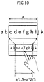
- FIG. 10 is a diagram illustrating an example of determining display target area based on the post-moving touched position and the magnifying power of the magnified view.
- FIG. 10 depicts a state in which the finger touches a portion between "e” and “f” of a character string "abcdefghijk".
- the magnifying glass is displayed on the upper side of the touched position, and the characters “cdefghi" are magnified and displayed on the magnifying glass.
- a symbol "a” be the size of the horizontal width of the magnifying glass and setting the magnifying power to 1.5
- an area with the horizontal width "a/1.5” including the touched position is displayed as the display target area on the magnifying glass.
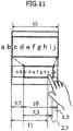
- FIG. 11 is a diagram depicting a specific example of determining the display target area based on the post-moving touched position and the magnifying power of the magnified view.
- FIG. 11 depicts a state in which the finger touches a character "i" in the characters "abcdefghij k". The magnifying glass is displayed on the upper side of the touched position, and the characters "cdefghij" are magnified and displayed on the magnifying glass.
- an area defined by the X-coordinate "3.7” and the X-coordinate "13. 7" becomes a horizontal range of the display target area. It may be sufficient that a vertical range of the display target area is so determined as to cover the touched position with the width of, e.g., "(Size of Vertical Width of Magnifying Glass) /N".
- Example 3 The hardware configuration and the function blocks in the Example 3 are the same as those in the Example 1, and hence the descriptions thereof are omitted. Further, then processes in the Example 3 are the same as in the Example 1 except processes, depicted in FIG. 9 , of determining the display target area and displaying the determined area on the magnifying glass, and therefore the description thereof is omitted.
- FIG. 9 is a diagram illustrating one example of a flowchart of processes of determining the display target area and displaying the determined area on the magnifying glass when detecting the touch event.
- a start of the processes of determining the display target area and displaying the determined area on the magnifying glass is triggered by, e.g. , touching the display unit 5 in the electronic device 1.
- a be the size of the horizontal width of the magnifying glass
- b be the initial value of the vertical width of the magnifying glass
- "x” be the X-coordinate of the touched position
- "y” be the Y-coordinate of the touched position
- N be the magnifying power.
- the electronic device 1 detects the touch event, and the processing is shifted to S12.
- the "down" event and the "move” event are detected as the touch events.
- the electronic device 1 obtains, as the display target area, display contents (bitmap image) in an area defined by the following coordinates, and the processing is shifted to S13.
- the electronic device 1 magnifies the bitmap image obtained in S12 by "N" in the vertical and horizontal directions, and the processing is shifted to S14.
- the electronic device 1 displays the bitmap image magnified in S13 on the display position of the magnifying glass, and the processing comes to an end.
- the electronic device 1 executes the processes in S12 and S13 as one example of displaying a display target area in a magnified view window.
- the electronic device 1 according to the Example 3 changes, based on the post-moving touched position and the magnifying power of the magnified view, the contents to be displayed on the magnifying glass.
- the contents displayed on the magnifying glass are moved with the movement of the touched position, thereby enabling the contents to be read with no sense of discomfort even when the finger moves.
- the broader display target area can be displayed in the magnified view window.
Landscapes
- Engineering & Computer Science (AREA)
- Theoretical Computer Science (AREA)
- General Engineering & Computer Science (AREA)
- Physics & Mathematics (AREA)
- General Physics & Mathematics (AREA)
- Human Computer Interaction (AREA)
- User Interface Of Digital Computer (AREA)
- Controls And Circuits For Display Device (AREA)
- Position Input By Displaying (AREA)
- Digital Computer Display Output (AREA)
Description
- The embodiments discussed herein are related to an electronic device and an information display program.
- In recent years, touch panel type electronic devices have spread, which may execute a variety of operations by a touch input onto a panel. A variety of touch panel type electronic devices are exemplified such as a mobile phone terminal, a smartphone, a tablet terminal, an e-book terminal and a personal computer (PC).
- One of the operations on the panel is an operation of selecting characters contained in a displayed image. When selecting the characters, the characters are hard to be selected due to the characters being small, and a selected portion is hard to be recognized because of being hidden under a finger as the case may be.
- To cope with these drawbacks, a technology (refer to, e.g., Patent document 1) is known, which displays the selected portion in magnification in another area.
- [Patent document 1] Japanese National Publication of International Patent Application No.
2012-521048 -
US 2011/0289462 discloses computing device magnification gesture techniques, in particular a magnifying window (a virtual loupe) defined with a gesture of two fingers. The gesture is defined by two touch points moving away from each other. The virtual loupe is placed such that the portion of user interface corresponding to the two initial points is magnified and the size of the virtual loupe is determined by the motion of the fingers while moving away. The centre of the virtual loupe as defined does not move while the loupe is displayed. The loupe could be placed at an offset position to leave the magnified portion unobscured. - However, a magnified view window (which will hereinafter be also referred to as a magnifying glass) for displaying the selected portion in magnification has hitherto been difficult to confirm the whole selected portion by looking down upon the selected portion because of a size being fixed and being moved with a movement of a finger.
- One aspect of the present invention aims at providing an electronic device and an information display program, which can display a broader display target area in a magnified view window.
- One aspect of the embodiments is exemplified by an electronic device as defined in
claim 1. Preferred features are defined in the dependent claims. - Another aspect of the embodiments can encompass an information display program to make a computer function as the electronic device described above, and a non-transitory computer readable recording medium on which the program is recorded. The recording medium readable by the computer etc. connotes a recording medium that can store information such as data and programs electrically, magnetically, optically, mechanically or by chemical action, which can be read from the computer etc.
-
-
FIG. 1 is a diagram illustrating one example of a hardware configuration of an electronic device; -
FIG. 2 is a diagram illustrating one example of function blocks of the electronic device; -
FIG. 3A is a diagram depicting a display example of a magnifying glass during an operation of selecting a setting menu screen; -
FIG. 3B is a diagram depicting a display example of the magnifying glass during the operation of selecting the setting menu screen; -
FIG. 3C is a diagram depicting a display example of the magnifying glass during the operation of selecting the setting menu screen; -
FIG. 4A is a diagram illustrating an example in which the magnifying glass is displayed at an uppermost portion of the screen; -
FIG. 4B is a diagram illustrating an example in which the magnifying glass is overlaid on selected characters and displayed at an uppermost portion of the screen; -
FIG. 5A is a diagram illustrating a display example of the magnifying glass before a finger touching the screen moves downward; -
FIG. 5B is a diagram illustrating a display example of the magnifying glass after the finger touching the screen has moved downward; -
FIG. 6A is a diagram illustrating a display example of the magnifying glass during an operation of selecting the characters; -
FIG. 6B is a diagram illustrating a display example of the magnifying glass during the operation of selecting the characters; -
FIG. 6C is a diagram illustrating a display example of the magnifying glass during the operation of selecting the characters; -
FIG. 7 is a diagram illustrating an example of calculating a display position and a display size of the magnifying glass when touching the screen; -
FIG. 8 is a diagram illustrating one example of a flowchart of processes when detecting a touch event; -
FIG. 9 is a diagram illustrating one example of a flowchart of processes of determining a display target area and displaying the display target area on the magnifying glass when detecting a touch event; -
FIG. 10 is a diagram illustrating an example of determining the display target area based on a post-moving touched position and a magnifying power of a magnified view; and -
FIG. 11 is a diagram illustrating a specific example of determining the display target area based on the post-moving touched position and the magnifying power of the magnified view. - An embodiment of the present invention will hereinafter be described based on the drawings. A configuration of the following embodiment is an exemplification, and the present invention is not limited to the configuration of the embodiment.
- The Example 1 is such an example that an electronic device magnifies and displays an area covering a touch position on a magnifying glass, and a size of the magnifying glass is enlarged corresponding to a movement of the touch position.
-
FIGS. 3A through 3C are diagrams each illustrating a display example of the magnifying glass during an operation to select a setting menu screen.FIGS. 3A through 3C respectively depict the examples of the setting menu screen of a smartphone. -
FIG. 3A depicts a state after touching a letter "M" of "Miracast" as one of menu items. A symbol "a1" indicates the magnifying glass displayed on the setting menu screen. A portion encircled by a dotted line of "b1" represents a position touched by a user. A portion encircled by a dotted line of "b2" represents a portion corresponding to the touched position indicated by "b1" in a magnifying glass a1. Note that the electronic device may display a marker like an image of a highlighter pen to facilitate recognition of the touched position, the maker being formed as, e.g., a frame of the dotted line of each of "b1" and "b2". In other words, on the screen of the actual smartphone, the portions encircled by the dotted lines of "b1" and "b2" may be displayed in a different background color from that of a peripheral area. The magnifying glass a1 is displayed on the upper side of a portion encircled by the dotted line of "b1". The characters "Miracast" containing the touched position indicated by "b1" and a peripheral area thereof are magnified and displayed on the magnifying glass a1. -
FIG. 3B illustrates a state after a finger moving to downward to a menu item "Others" with the finger not being taken off from the state of touching the letter "M" of "Miracast" inFIG. 3A . A symbol "a2" indicates the magnifying glass displayed on a setting menu screen. A portion encircled by a dotted line of "b3" depicts a trajectory of the finger when moving downward to the menu item "Others" with the finger not being taken off from the state of touching the letter "M" of "Miracast". A portion encircled by a dotted line of "b4" indicates a portion corresponding to the finger's trajectory indicated by "b3" in the magnifying glass a2. Note that the electronic device may also display the marker like the image of the highlighter pen, the marker being formed as the frame of the dotted line of each of "b3" and "b4", to facilitate the recognition of the trajectory traced by the finger. In other words, on the screen of the actual smartphone, the portions encircled by the dotted lines of "b3" and "b4" may be displayed in the different background color from that of the peripheral area. A view of the magnifying glass a2 is enlarged downward to an upper area of the position of the finger after being moved. The position of the finger after being moved and the upper area thereof are magnified and displayed on the magnifying glass a2. -
FIG. 3C illustrates a state after the finger moving upward to characters "Setting" as a menu title with the finger not being taken off subsequent to the downward movement to the menu item "Others" inFIG. 3B . A symbol "a3" represents a magnifying glass displayed on the setting menu screen. A portion encircled by a dotted line of "b5" represents a trajectory of the finger when moving upward to the characters "Setting" as the menu title with the finger not being taken off through the state inFIG. 3B from the state inFIG. 3A . A portion encircled by a dotted line of "b6" represents a portion corresponding to the finger's trajectory on the screen of the smartphone in the magnifying glass a3. However, the finger' s trajectory corresponding to the portion encircled by the dotted line of "b6" is not depicted because of being positioned under the magnifying glass a3. The characters "Setting" and the peripheral area thereof are magnified and displayed on the magnifying glass a3. Note that the electronic device may display the marker like the image of the highlighter pen to facilitate the recognition of the trajectory traced by the finger, the maker being formed as, e.g., the frame of the dotted line of each of "b5" and "b6". In other words, on the screen of the actual smartphone, the portions encircled by the dotted lines of "b5" and "b6" may be displayed in the different background color from that of the peripheral area. - In the example of
FIG. 3C , when the finger moves upward, it is taken into consideration that a text is read normally downward, and the electronic device does not enlarge the size of the magnifying glass upward from the touched position before the movement. However, the electronic device may enlarge the size of the magnifying glass depending on a content displayed on the screen even when the finger moves upward. Further,FIGS. 3A through 3C depict the examples in which a size of horizontal width of the magnifying glass is fixed, however, the size of horizontal width of the magnifying glass inFIG. 3A may be enlarged from a smaller size than a size of horizontal width of the screen to the size of horizontal width of the screen. In other words, the size of horizontal width of the magnifying glass does not need to be fixed in the Example 1. -
FIG. 4A is a diagram illustrating an example of displaying the magnifying glass at an uppermost portion of the screen. To be specific,FIG. 4A depicts a state in which a position between "FINE" and "WEATHER" of a sentence "IT IS A FINE WEATHER TODAY. " is touched by the finger. The magnifying glass is displayed on the upper side of the touched position, and the characters anterior and posterior to the touched position are magnified and displayed on the magnifying glass.FIG. 4B is a diagram illustrating such an example that the magnifying glass is overlaid on selected characters, the view being given at the uppermost portion of the screen.FIG. 4B , similarly toFIG. 4A , depicts the state in which the position between "FINE" and "WEATHER" of the sentence "IT IS A FINE WEATHER TODAY." is touched by the finger. The sentence "IT IS A FINE WEATHER TODAY." is, however, displayed in a position near the uppermost portion of the screen. The magnifying glass is so displayed as to be overlaid on the selected characters because of being unable to get space for displaying on the upper side of the touched position. Thus, the magnifying glass, when moving up to the uppermost portion of the screen, without further moving or disappearing, is displayed at the uppermost portion of the screen in a state of keeping a predetermined size. -
FIG. 1 is a diagram illustrating one example of a hardware configuration of anelectronic device 1. Theelectronic device 1 includes aprocessor 2, astorage unit 3, a touch sensor unit 4, adisplay unit 5, awireless unit 6 and an audio Input/Output (I/O) unit 7. - The
processor 2 is, e.g., a CPU (Central Processing Unit) or a DSP (Digital Signal Processor). Thestorage unit 3 includes a ROM (Read Only Memory) 31 and a RAM (Random Access Memory) 32. TheROM 31 is a memory in which to store a variety of computer programs and data used by theprocessor 2 when executing the respective computer programs. TheRAM 32 includes both of a volatile memory and a nonvolatile memory. TheRAM 32 provides theprocessor 2 with a storage area for loading the computer program stored in theROM 31 and an operation area. Further, theRAM 32 is used as a buffer for temporarily retaining the data. - The touch sensor unit 4 is one of position input devices and acquires, when detecting that the
display unit 5 is touched, a coordinate of the touched position of the finger on the screen and outputs the acquired coordinate to theprocessor 2. The touch sensor unit 4 may be of any of a resistance film type, a surface acoustic wave type, an infrared-ray type, an electromagnetic induction type, an electrostatic capacity type, etc. - The
display unit 5 is, e.g., a liquid crystal display (LCD). Thedisplay unit 5 displays screen data according to a signal inputted from theprocessor 2. - The
wireless unit 6 converts a radio signal received via an antenna into an electric signal and outputs the electric signal to theprocessor 2, or converts the electric signal inputted from theprocessor 2 into the radio signal and transmits the radio signal via the antenna. Thewireless unit 6 is an electronic circuit that supports, e.g., the 3G (third-generation) mobile communication system. - The audio I/O unit 7 converts an audio signal inputted from an audio input device such as a microphone into the electric signal and outputs the electric signal to the
processor 2, or converts the electric signal inputted from theprocessor 2 into the audio signal and outputs the audio signal to an audio output device such as a speaker. - Note that the hardware configuration of the
electronic device 1 may be, without being limited to the configuration illustrated inFIG. 1 , properly modified such as addition, replacement and deletion. Theelectronic device 1 is exemplified by a mobile phone terminal, a smartphone, a tablet terminal, an e-book terminal and a PC. -
FIG. 2 is a diagram illustrating one example of function blocks of theelectronic device 1. Theelectronic device 1 includes, as the function blocks, a magnified viewwindow display unit 10, a magnified view windowsize change unit 11 and a view targetarea determining unit 12. Theprocessor 2 executes the computer programs deployed in an executable manner on thestorage unit 3 as the magnified viewwindow display unit 10, the magnified view windowsize change unit 11 and the view targetarea determining unit 12. However, hardware circuits may execute any one of the magnified viewwindow display unit 10, the magnified view windowsize change unit 11 and the view targetarea determining unit 12, or a part of processes of these units. - The magnified view
window display unit 10 detects that thedisplay unit 5 is touched and display the magnifying glass on the upper side of the touched position. The horizontal width of the magnifying glass maybe the same as a size of width of thedisplay unit 5 and may also be smaller than the size of width of thedisplay unit 5. A vertical width of the magnifying glass may be a predetermined size being set beforehand as an initial value. The magnified viewwindow display unit 10 magnifies and displays contents of the areas anterior and posterior to the touched position on the magnifying glass. Note that when unable to get space for displaying the magnifying glass on the upper side of the touched position, theelectronic device 1 may display the magnifying glass so as to be overlaid on the touched position. - The magnified view window
size change unit 11 detects a movement of the touched position and changes the size of the magnifying glass. The magnified view windowsize change unit 11, e.g., when the touched position moves downward, enlarges the vertical width of the magnifying glass, which is displayed by the magnified viewwindow display unit 10 before the finger moves, up to the touched position after being moved. Further, the magnified view windowsize change unit 12 may enlarge the horizontal width of the magnifying glass up to the size of horizontal width of the screen. On the other hand, when the touched position moves upward, the magnified view windowsize change unit 11 may display, without enlarging the size of the magnifying glass, the magnifying glass including the post-moving touched position with the vertical width being the initial value. - The view target
area determining unit 12 determines a display target area including the post-moving touched position corresponding to the size of the magnifying glass, and displays the determined area on a magnified view window. The view targetarea determining unit 12 may also determine, as the display target area, an area of a range that includes the post-moving touched position and that can be displayed in the magnifying glass. The pre-moving touched position is one example of a first touched position. Furthermore, the post-moving touched position is one example of a second touched position. The touched position after the finger moves upward with the finger not being taken off subsequent to the downward movement as illustrated inFIG. 3C is one example of a third position. -
FIG. 7 is a diagram illustrating one example of calculating a display position and a display size of the magnifying glass of theelectronic device 1. InFIG. 7 , a left upward coordinate of the screen of theelectronic device 1 is (0, 0). Further, a right side in a horizontal direction (an X-axis direction) and a lower side in a vertical direction (a Y-axis direction) are positive sides. When the finger touches the screen of theelectronic device 1, a touch panel is notified of a coordinate (x, y) of the touched position of the finger. InFIG. 7 , the position in which the finger touches the screen of theelectronic device 1 is indicated by a coordinate (x1, y1). A symbol "a" represents a size of horizontal width of the magnifying glass, "b" designates an initial value of a size of vertical width of the magnifying glass, and "c" denotes a distance from a lower edge of the magnifying glass to the finger. In the example ofFIG. 7 , the horizontal width of the magnifying glass is to be a width of the screen. Theelectronic device 1, when the screen is touched, displays the magnifying glass having the horizontal size "a" and the vertical size "b" in a position defined by a right downward coordinate "(x3, y3) = (a, y1-c)" and a left upward coordinate "(x2, y2) = (0, y1-b-c)". -
FIG. 8 is a diagram illustrating one example of a flowchart of processes when detecting a touch event. The touch event occurs when detecting a touch operation on the screen of theelectronic device 1. The touch event includes, e.g., a "down" event occurring when the finger touches the screen, a "move" event occurring when the touch finger moves, and an "up" event occurring when the finger takes off the screen. A start of the processes when detecting the touch event is triggered by, e.g., touching thedisplay unit 5 of theelectronic device 1 and the magnifying glass being displayed by the magnified viewwindow display unit 10. - In S01, the
electronic device 1 detects that thedisplay unit 5 is touched by the finger, and the processing is shifted to S02. In S02, theelectronic device 1 stores the coordinate (x1, y1) of the touched position as a coordinate of an origin in thestorage unit 3, and the processing is shifted to S03. In S03, theelectronic device 1 detects the touch event and stores, in thestorage unit 3, a coordinate (x, y) of the touched position when the touch event occurs, and the processing is shifted to S04. In S04, theelectronic device 1 determines whether the detected touch event is the "move" event, and the processing is shifted to S05 when being the "move" event but is diverted to S08 whereas when not being the "move" event. - In S05, the
electronic device 1 compares a Y-coordinate "y1" of the origin with a Y-coordinate "y" of the post-moving position of the finger, and the processing is shifted to S06 when "y1 > y" but is diverted to S07 whereas when "y1 < y". The process in S06 is a process in case of "y1 > y", i.e., when the finger moves upward from the touched origin. In S06, theelectronic device 1 sets a size of the magnified view window to a size of an area defined by a left upward coordinate (0, y-b-c) and a right downward coordinate (x3, y-c) by the magnified view windowsize change unit 11. Theelectronic device 1 magnifies and displays the determined display target area on the magnifying glass by the view targetarea determining unit 12. The process in S07 is a process in case of "y1 ≤ y", i.e., when the finger moves downward from the touched origin. In S07, theelectronic device 1 sets the size of the magnified view window to a size of an area defined by a left upward coordinate (x2, y2) and a right downward coordinate (x3, y-c) by the magnified view windowsize change unit 11. Theelectronic device 1 magnifies and displays the determined display target area on the magnifying glass by the view targetarea determining unit 12. After the magnifying glass is displayed in S06 or S07, theelectronic device 1 loops the processing back to S03. - The process in S08 is a process when the event is determined not to be the "move" event in S04. In S08, the
electronic device 1 determines whether the detected touch event is the "up" event, and the processing is shifted to S09 when being the "up" event but is looped back to S03 whereas when not being the "up" event. In S09, theelectronic device 1 hides the magnifying glass, resulting in finishing the processes when detecting the touch event. Theelectronic device 1 executes the processes in S06 and S07 as one example of enlarging a size of a magnified view window. - The
electronic device 1 according to Example 1 dynamically enlarges the size of the magnifying glass corresponding to the movement of the touched position. Therefore, not only the area with the fixed size including the touched position but also the broader area including the post-moving touched position, are displayed as the display target area on the magnifying glass having the enlarged size. Accordingly, this view facilitates looking down upon the broader area including the touched position. Further, theelectronic device 1 can display the magnifying glass over also the menu screen etc. not based on a premise of editing in addition to the images based on the premise of editing such as copying and pasting. Hence, when hard to recognize a selected portion concealed by the finger due to the characters being small also on the menu screen etc. not based on the premise of editing, it is feasible to easily confirm the area including the touched position. - The Example 2 is an example of enlarging the size in the vertical direction while fixing the horizontal width of the magnifying glass.
FIG. 5A is a diagram illustrating a display example of the magnifying glass before the finger touching the screen moves downward. To be specific,FIG. 5A depicts a state in which the finger moves rightward to between "FINE" and "WEATHER" after touching a left edge of a sentence "IT IS A FINE WEATHER TODAY. ". InFIG. 5A , the horizontal width of the magnifying glass is the same of the horizontal width of the screen.FIG. 5B is a diagram illustrating a display example of the magnifying glass after the finger touching the screen moves downward. Specifically,FIG. 5B depicts a state in which the finger moves downward to "BE" in the sentence "IT WILL BE RAINY TOMORROW. " provided two lines below after the state inFIG. 5A . At this time, the size of the magnifying glass is enlarged downward, while the size of the horizontal width of the magnifying glass remains fixed. - The hardware configuration and then function blocks in the Example 2 are the same as those in the Example 1, and hence the descriptions thereof are omitted. Further, an operational example in the Example 2 is the same as in the Example 1 except a point that the size of the horizontal width of the magnifying glass remains fixed, and hence the description thereof is omitted.
- In the
electronic device 1 according to the Example 2, the horizontal width of the magnifying glass is fixed, while only the size is enlarged only in the vertical direction, and therefore the magnifying glass does not move in the horizontal direction. Even when the contents to be displayed on the magnifying glass are changed with the movement of the finger, the horizontal width is fixed, and an advantage of being easy to read is yielded. - The Example 3 is an example that the display target area is determined based on the post-moving touched position and a magnifying power of the magnified view.
FIGS. 6A through 6C are diagrams each illustrating a display example of the magnifying glass during a character selecting operation. -
FIG. 6A depicts a state in which the finger moves rightward to between "FINE" and "WEATHER" after touching a left edge of sentences "IT IS A FINE WEATHER TODAY. BUT, IT WILL BE RAINY TOMMOROW.". At this time, the characters "FINE WEATHER T" are displayed on the magnifying glass, and an X-coordinate of a position (between "FINE" and "WEATHER") corresponding to the touched position is equal to an X-coordinate of the touched position.FIG. 6B depicts a state after the finger has moved to between "WEATHER" and "TODAY" and further moved rightward subsequent to the state inFIG. 6A . At this time, the characters "WEATHER TODAY" are displayed on the magnifying glass, and the X-coordinate of a position (between "WEATHER" and "TODAY") corresponding to the touched position is equal to the X-coordinate of the touched position.FIG. 6C depicts a state after the finger has moved to a right edge, i.e., "BUT," of the sentence and further moved rightward subsequent to the state inFIG. 6B . At this time, the characters "BUT, IT WILL BE RAINY TOMORROW" are displayed on the magnifying glass, and the X-coordinate of a position (right side of "BUT,") corresponding to the touched position is equal to the X-coordinate of the touched position. - Each of the display target areas illustrated in
FIGS. 6A through 6C is determined by the view targetarea determining unit 12. To be specific, the view targetarea determining unit 12 calculates a width of the display target area from the magnifying power of the magnified view and the size of the horizontal width of the magnified view window. Next, the view targetarea determining unit 12 segments the width of the display target area at the same ratio as a ratio of a distance from the left edge of the screen to the touched position to a distance from the touched position to the right edge of the screen, and calculates the distance from the left edge of the display target area to the touched position and the distance from the touched position to the right edge of the display target area. The view targetarea determining unit 12 subtracts the distance from the left edge of the display target area to the touched position from the X-coordinate of the touched position, thereby determining the X-coordinate of the left edge of the display target area. Furthermore, the view targetarea determining unit 12 adds the distance from the touched position to the right edge of the display target area to the X-coordinate of the touched position, thereby determining the X-coordinate of the right edge of the display target area. Thus, the display target area is determined from the post-moving touched position and the magnifying power of the magnified view, whereby the contents displayed on the magnifying glass are moved with the movement of the touched position. -
FIG. 10 is a diagram illustrating an example of determining display target area based on the post-moving touched position and the magnifying power of the magnified view.FIG. 10 depicts a state in which the finger touches a portion between "e" and "f" of a character string "abcdefghijk". The magnifying glass is displayed on the upper side of the touched position, and the characters "cdefghi" are magnified and displayed on the magnifying glass. When letting a symbol "a" be the size of the horizontal width of the magnifying glass and setting the magnifying power to 1.5, an area with the horizontal width "a/1.5" including the touched position is displayed as the display target area on the magnifying glass. -
FIG. 11 is a diagram depicting a specific example of determining the display target area based on the post-moving touched position and the magnifying power of the magnified view.FIG. 11 depicts a state in which the finger touches a character "i" in the characters "abcdefghij k". The magnifying glass is displayed on the upper side of the touched position, and the characters "cdefghij" are magnified and displayed on the magnifying glass. The size of the horizontal width of the magnifying glass is set to a = 15, the X-coordinate of the touched position is given by x = 11, and the magnifying power is set to N = 1.5, in which case the X-coordinate of the left edge of the display target area and the X-coordinate of the right edge thereof are obtained by the following calculation. - X-Coordinate of Left Edge: (a/N) × x/a = (15/1.5) × 11/15 = 7.3 x - 7.3 = 11-7.3 = 3.7
- X-Coordinate of Right Edge: (a/N) - 7.3 = 10 - 7.3 = 2.7 x + 2.7 = 11 + 2.7 = 13.7
- Namely, an area defined by the X-coordinate "3.7" and the X-coordinate "13. 7" becomes a horizontal range of the display target area. It may be sufficient that a vertical range of the display target area is so determined as to cover the touched position with the width of, e.g., "(Size of Vertical Width of Magnifying Glass) /N".
- The hardware configuration and the function blocks in the Example 3 are the same as those in the Example 1, and hence the descriptions thereof are omitted. Further, then processes in the Example 3 are the same as in the Example 1 except processes, depicted in
FIG. 9 , of determining the display target area and displaying the determined area on the magnifying glass, and therefore the description thereof is omitted. -
FIG. 9 is a diagram illustrating one example of a flowchart of processes of determining the display target area and displaying the determined area on the magnifying glass when detecting the touch event. A start of the processes of determining the display target area and displaying the determined area on the magnifying glass is triggered by, e.g. , touching thedisplay unit 5 in theelectronic device 1. Herein, let "a" be the size of the horizontal width of the magnifying glass, "b" be the initial value of the vertical width of the magnifying glass, "x" be the X-coordinate of the touched position, "y" be the Y-coordinate of the touched position and "N" be the magnifying power. The example inFIG. 9 exemplifies a case of N = 1.5, however, it does not mean that the magnifying power is limited to "1.5". - In S11, the
electronic device 1 detects the touch event, and the processing is shifted to S12. In S11, the "down" event and the "move" event are detected as the touch events. - In S12, the
electronic device 1 obtains, as the display target area, display contents (bitmap image) in an area defined by the following coordinates, and the processing is shifted to S13. - X-Coordinate of Left Edge: x0 = x - (axN) × x/a
- X-Coordinate of Right Edge: x1 = x0 + (a×N)
- Y-Coordinate of Left Edge: y0 = y - b
- Y-Coordinate of Right Edge: y1 = y + b
- In S13, the
electronic device 1 magnifies the bitmap image obtained in S12 by "N" in the vertical and horizontal directions, and the processing is shifted to S14. In S14, theelectronic device 1 displays the bitmap image magnified in S13 on the display position of the magnifying glass, and the processing comes to an end. Theelectronic device 1 executes the processes in S12 and S13 as one example of displaying a display target area in a magnified view window. - The
electronic device 1 according to the Example 3 changes, based on the post-moving touched position and the magnifying power of the magnified view, the contents to be displayed on the magnifying glass. The contents displayed on the magnifying glass are moved with the movement of the touched position, thereby enabling the contents to be read with no sense of discomfort even when the finger moves. - According to the electronic device and the information display program of the disclosure, the broader display target area can be displayed in the magnified view window.
Claims (5)
- An electronic device (1) comprising:a touch position detection unit (4) configured to detect a touched position on a touch panel, the touched position being detected by an X component and a Y component of an X-Y coordinate;a magnified view window display unit (10) configured to display a magnified view window to magnify and display an area including a first touched position, the first touched position being a position at which a single touch operation is detected on the touch panela magnified view window size change unit (11) configured to enlarge a size of the magnified view window based on the first touched position and a first destination position when a single touch moving operation to move a single touch position to the first destination position from the first touched position is detected, the first destination position being a position where the Y coordinate value is larger than the first touched position; anda view target area determining unit (12) configured to determine a display target area including the first destination position corresponding to the size of the magnified view window and to display the display target area including the first destination position on the magnified view window,wherein, when the touched position further moves to a second destination position from the first destination position, the magnified view window size change unit (11) narrows the size of the magnified view window in the Y direction based on the second destination position, the second destination position being a position where the Y coordinate value is smaller than the first destination position, andthe view target area determining unit (12) determines a display target area including the second destination position corresponding to the size of the magnified view window and displays the display target area including the second destination position on the magnified view window.
- The electronic device (1) according to claim 1, wherein the magnified view window size change unit (11) is configured to fix a width of the magnified view window in the X direction, and to enlarge the size of the magnified view window in the Y direction.
- The electronic device (1) according to claim 1 or 2, wherein the view target area determining unit (12) is configured to associate the first destination position with a predetermined position of the magnified view window, and to determine the display target area in a range enabled to be displayed on the magnified view window at a predetermined magnifying power.
- The electronic device (1) according to claim 3, wherein a X coordinate of the predetermined position of the magnified view window on a screen is coincident with a X coordinate of the second touched position on the screen.
- An information display program to make a computer execute:detecting a touched position on a touch panel, the touched position being detected by an X component and a Y component of an X-Y coordinate;displaying a magnified view window to magnify and display an area including a first touched position, the first touched position being a position at which a single touch operation is detected on the touch panel;enlarging a size of the magnified view window based on the first touched position and a first destination position when a single touch moving operation to move a single touch position to the first destination position from the first touched position is detected, the first destination position being a position where the Y coordinate value is larger than the first touched position;determining the display target area including the first destination position corresponding to the size of the magnified view window;displaying the display target area including the first destination position in the magnified view window;narrowing, when the touched position further moves to a second destination position from the first destination position, the size of the magnified view window in the Y direction based on the second destination position, the second destination position being a position where the Y coordinate value is smaller than the first destination position;determining the display target area including the second destination position corresponding to the size of the magnified view window; anddisplaying the display target area including the second destination position on the magnified view window.
Applications Claiming Priority (1)
| Application Number | Priority Date | Filing Date | Title |
|---|---|---|---|
| JP2014079479A JP6241356B2 (en) | 2014-04-08 | 2014-04-08 | Electronic device and information display program |
Publications (3)
| Publication Number | Publication Date |
|---|---|
| EP2930600A2 EP2930600A2 (en) | 2015-10-14 |
| EP2930600A3 EP2930600A3 (en) | 2015-10-28 |
| EP2930600B1 true EP2930600B1 (en) | 2018-04-04 |
Family
ID=52824039
Family Applications (1)
| Application Number | Title | Priority Date | Filing Date |
|---|---|---|---|
| EP15161564.8A Not-in-force EP2930600B1 (en) | 2014-04-08 | 2015-03-30 | Electronic device and information display program |
Country Status (3)
| Country | Link |
|---|---|
| US (1) | US9678646B2 (en) |
| EP (1) | EP2930600B1 (en) |
| JP (1) | JP6241356B2 (en) |
Families Citing this family (4)
| Publication number | Priority date | Publication date | Assignee | Title |
|---|---|---|---|---|
| KR102324083B1 (en) * | 2014-09-01 | 2021-11-09 | 삼성전자주식회사 | Method for providing screen magnifying and electronic device thereof |
| US10275436B2 (en) * | 2015-06-01 | 2019-04-30 | Apple Inc. | Zoom enhancements to facilitate the use of touch screen devices |
| CN112584280B (en) * | 2019-09-27 | 2022-11-29 | 百度在线网络技术(北京)有限公司 | Control method, device, equipment and medium for intelligent equipment |
| CN114185628B (en) * | 2021-11-19 | 2024-04-12 | 北京奇艺世纪科技有限公司 | Picture adjustment method, device and equipment of iOS (integrated operation system) and computer readable medium |
Family Cites Families (13)
| Publication number | Priority date | Publication date | Assignee | Title |
|---|---|---|---|---|
| AU2003288689A1 (en) * | 2002-11-29 | 2004-06-23 | Koninklijke Philips Electronics N.V. | User interface with displaced representation of touch area |
| DE10310794B4 (en) * | 2003-03-12 | 2012-10-18 | Hewlett-Packard Development Co., L.P. | Operating device and communication device |
| US7743348B2 (en) * | 2004-06-30 | 2010-06-22 | Microsoft Corporation | Using physical objects to adjust attributes of an interactive display application |
| US20080238947A1 (en) * | 2007-03-27 | 2008-10-02 | Keahey T Alan | System and method for non-linear magnification of images |
| JP5001182B2 (en) * | 2008-01-10 | 2012-08-15 | パナソニック株式会社 | Display control apparatus, electronic device, display control method, and program |
| US9875013B2 (en) | 2009-03-16 | 2018-01-23 | Apple Inc. | Methods and graphical user interfaces for editing on a multifunction device with a touch screen display |
| JP2011165023A (en) * | 2010-02-12 | 2011-08-25 | Panasonic Corp | Input device |
| US20110289462A1 (en) * | 2010-05-20 | 2011-11-24 | Microsoft Corporation | Computing Device Magnification Gesture |
| US9323415B2 (en) * | 2011-06-29 | 2016-04-26 | Nokia Technologies Oy | Apparatus and associated methods related to touch sensitive displays |
| US9785343B2 (en) * | 2011-12-01 | 2017-10-10 | Sony Mobile Communications Inc. | Terminal device, image display method, and storage medium |
| JP5982884B2 (en) * | 2012-03-08 | 2016-08-31 | ソニー株式会社 | Display control apparatus, display control method, and computer-readable recording medium |
| KR20140080220A (en) * | 2012-12-20 | 2014-06-30 | 삼성전자주식회사 | Method for zoomming for contents an electronic device thereof |
| US11003351B2 (en) * | 2012-12-26 | 2021-05-11 | Gree, Inc. | Display processing method and information device |
-
2014
- 2014-04-08 JP JP2014079479A patent/JP6241356B2/en not_active Expired - Fee Related
-
2015
- 2015-03-30 EP EP15161564.8A patent/EP2930600B1/en not_active Not-in-force
- 2015-03-31 US US14/675,130 patent/US9678646B2/en active Active
Non-Patent Citations (1)
| Title |
|---|
| None * |
Also Published As
| Publication number | Publication date |
|---|---|
| EP2930600A2 (en) | 2015-10-14 |
| US9678646B2 (en) | 2017-06-13 |
| JP2015201039A (en) | 2015-11-12 |
| US20150286378A1 (en) | 2015-10-08 |
| EP2930600A3 (en) | 2015-10-28 |
| JP6241356B2 (en) | 2017-12-06 |
Similar Documents
| Publication | Publication Date | Title |
|---|---|---|
| US9678659B2 (en) | Text entry for a touch screen | |
| KR101892567B1 (en) | Method and apparatus for moving contents on screen in terminal | |
| US9367238B2 (en) | Terminal apparatus and input correction method | |
| US10534524B2 (en) | Method and device for controlling reproduction speed of multimedia content | |
| EP2657811B1 (en) | Touch input processing device, information processing device, and touch input control method | |
| EP2613244A2 (en) | Apparatus and method for displaying screen on portable device having flexible display | |
| US20130215018A1 (en) | Touch position locating method, text selecting method, device, and electronic equipment | |
| US9665216B2 (en) | Display control device, display control method and program | |
| US20150212724A1 (en) | Manipulation input device, manipulation input method, manipulation input program, and electronic apparatus | |
| US20120280898A1 (en) | Method, apparatus and computer program product for controlling information detail in a multi-device environment | |
| EP2560086B1 (en) | Method and apparatus for navigating content on screen using pointing device | |
| KR20140140957A (en) | Method for mirroring screen data, machine-readable storage medium and electronic device | |
| CN105745612B (en) | Re-sizing technique for displaying content | |
| US8762840B1 (en) | Elastic canvas visual effects in user interface | |
| EP2613247A2 (en) | Method and apparatus for displaying keypad in terminal having touch screen | |
| EP2778880B1 (en) | Method for controlling display function and an electronic device thereof | |
| US20140245223A1 (en) | Mobile terminal and method for controlling display of object on touch screen | |
| US9658714B2 (en) | Electronic device, non-transitory storage medium, and control method for electronic device | |
| KR20150025214A (en) | Method for displaying visual object on video, machine-readable storage medium and electronic device | |
| CN103455242B (en) | Screen picture cutting method and device | |
| US10042445B1 (en) | Adaptive display of user interface elements based on proximity sensing | |
| US9678646B2 (en) | Electronic device and computer-readable recording medium storing information display program | |
| CN107977126A (en) | A kind of function choosing-item shows method, apparatus, equipment and shows interface | |
| EP3051401B1 (en) | Image display apparatus, image enlargement method, and image enlargement program | |
| CN110494834A (en) | Touch panel device, its display control method and program |
Legal Events
| Date | Code | Title | Description |
|---|---|---|---|
| PUAL | Search report despatched |
Free format text: ORIGINAL CODE: 0009013 |
|
| PUAI | Public reference made under article 153(3) epc to a published international application that has entered the european phase |
Free format text: ORIGINAL CODE: 0009012 |
|
| AK | Designated contracting states |
Kind code of ref document: A2 Designated state(s): AL AT BE BG CH CY CZ DE DK EE ES FI FR GB GR HR HU IE IS IT LI LT LU LV MC MK MT NL NO PL PT RO RS SE SI SK SM TR |
|
| AX | Request for extension of the european patent |
Extension state: BA ME |
|
| AK | Designated contracting states |
Kind code of ref document: A3 Designated state(s): AL AT BE BG CH CY CZ DE DK EE ES FI FR GB GR HR HU IE IS IT LI LT LU LV MC MK MT NL NO PL PT RO RS SE SI SK SM TR |
|
| AX | Request for extension of the european patent |
Extension state: BA ME |
|
| RIC1 | Information provided on ipc code assigned before grant |
Ipc: G06F 3/0481 20130101AFI20150918BHEP Ipc: G06F 3/0488 20130101ALI20150918BHEP |
|
| 17P | Request for examination filed |
Effective date: 20160209 |
|
| RBV | Designated contracting states (corrected) |
Designated state(s): AL AT BE BG CH CY CZ DE DK EE ES FI FR GB GR HR HU IE IS IT LI LT LU LV MC MK MT NL NO PL PT RO RS SE SI SK SM TR |
|
| 17Q | First examination report despatched |
Effective date: 20161006 |
|
| STAA | Information on the status of an ep patent application or granted ep patent |
Free format text: STATUS: EXAMINATION IS IN PROGRESS |
|
| GRAP | Despatch of communication of intention to grant a patent |
Free format text: ORIGINAL CODE: EPIDOSNIGR1 |
|
| STAA | Information on the status of an ep patent application or granted ep patent |
Free format text: STATUS: GRANT OF PATENT IS INTENDED |
|
| RIC1 | Information provided on ipc code assigned before grant |
Ipc: G06F 3/0488 20130101ALI20170929BHEP Ipc: G06F 3/0481 20130101AFI20170929BHEP Ipc: G06F 3/0484 20130101ALI20170929BHEP Ipc: G06T 3/40 20060101ALI20170929BHEP |
|
| INTG | Intention to grant announced |
Effective date: 20171025 |
|
| GRAS | Grant fee paid |
Free format text: ORIGINAL CODE: EPIDOSNIGR3 |
|
| GRAA | (expected) grant |
Free format text: ORIGINAL CODE: 0009210 |
|
| STAA | Information on the status of an ep patent application or granted ep patent |
Free format text: STATUS: THE PATENT HAS BEEN GRANTED |
|
| AK | Designated contracting states |
Kind code of ref document: B1 Designated state(s): AL AT BE BG CH CY CZ DE DK EE ES FI FR GB GR HR HU IE IS IT LI LT LU LV MC MK MT NL NO PL PT RO RS SE SI SK SM TR |
|
| REG | Reference to a national code |
Ref country code: GB Ref legal event code: FG4D |
|
| REG | Reference to a national code |
Ref country code: CH Ref legal event code: EP |
|
| REG | Reference to a national code |
Ref country code: AT Ref legal event code: REF Ref document number: 986266 Country of ref document: AT Kind code of ref document: T Effective date: 20180415 |
|
| REG | Reference to a national code |
Ref country code: IE Ref legal event code: FG4D |
|
| REG | Reference to a national code |
Ref country code: DE Ref legal event code: R096 Ref document number: 602015009437 Country of ref document: DE |
|
| REG | Reference to a national code |
Ref country code: NL Ref legal event code: MP Effective date: 20180404 |
|
| REG | Reference to a national code |
Ref country code: LT Ref legal event code: MG4D |
|
| PG25 | Lapsed in a contracting state [announced via postgrant information from national office to epo] |
Ref country code: NL Free format text: LAPSE BECAUSE OF FAILURE TO SUBMIT A TRANSLATION OF THE DESCRIPTION OR TO PAY THE FEE WITHIN THE PRESCRIBED TIME-LIMIT Effective date: 20180404 |
|
| PG25 | Lapsed in a contracting state [announced via postgrant information from national office to epo] |
Ref country code: BG Free format text: LAPSE BECAUSE OF FAILURE TO SUBMIT A TRANSLATION OF THE DESCRIPTION OR TO PAY THE FEE WITHIN THE PRESCRIBED TIME-LIMIT Effective date: 20180704 Ref country code: FI Free format text: LAPSE BECAUSE OF FAILURE TO SUBMIT A TRANSLATION OF THE DESCRIPTION OR TO PAY THE FEE WITHIN THE PRESCRIBED TIME-LIMIT Effective date: 20180404 Ref country code: LT Free format text: LAPSE BECAUSE OF FAILURE TO SUBMIT A TRANSLATION OF THE DESCRIPTION OR TO PAY THE FEE WITHIN THE PRESCRIBED TIME-LIMIT Effective date: 20180404 Ref country code: ES Free format text: LAPSE BECAUSE OF FAILURE TO SUBMIT A TRANSLATION OF THE DESCRIPTION OR TO PAY THE FEE WITHIN THE PRESCRIBED TIME-LIMIT Effective date: 20180404 Ref country code: PL Free format text: LAPSE BECAUSE OF FAILURE TO SUBMIT A TRANSLATION OF THE DESCRIPTION OR TO PAY THE FEE WITHIN THE PRESCRIBED TIME-LIMIT Effective date: 20180404 Ref country code: SE Free format text: LAPSE BECAUSE OF FAILURE TO SUBMIT A TRANSLATION OF THE DESCRIPTION OR TO PAY THE FEE WITHIN THE PRESCRIBED TIME-LIMIT Effective date: 20180404 Ref country code: AL Free format text: LAPSE BECAUSE OF FAILURE TO SUBMIT A TRANSLATION OF THE DESCRIPTION OR TO PAY THE FEE WITHIN THE PRESCRIBED TIME-LIMIT Effective date: 20180404 Ref country code: NO Free format text: LAPSE BECAUSE OF FAILURE TO SUBMIT A TRANSLATION OF THE DESCRIPTION OR TO PAY THE FEE WITHIN THE PRESCRIBED TIME-LIMIT Effective date: 20180704 |
|
| REG | Reference to a national code |
Ref country code: DE Ref legal event code: R082 Ref document number: 602015009437 Country of ref document: DE Representative=s name: HASELTINE LAKE KEMPNER LLP, DE Ref country code: DE Ref legal event code: R082 Ref document number: 602015009437 Country of ref document: DE Representative=s name: HL KEMPNER PATENTANWALT, RECHTSANWALT, SOLICIT, DE Ref country code: DE Ref legal event code: R082 Ref document number: 602015009437 Country of ref document: DE Representative=s name: HASELTINE LAKE LLP, DE Ref country code: DE Ref legal event code: R081 Ref document number: 602015009437 Country of ref document: DE Owner name: FUJITSU CONNECTED TECHNOLOGIES LTD., KAWASAKI-, JP Free format text: FORMER OWNER: FUJITSU LIMITED, KAWASAKI-SHI, KANAGAWA, JP |
|
| PG25 | Lapsed in a contracting state [announced via postgrant information from national office to epo] |
Ref country code: LV Free format text: LAPSE BECAUSE OF FAILURE TO SUBMIT A TRANSLATION OF THE DESCRIPTION OR TO PAY THE FEE WITHIN THE PRESCRIBED TIME-LIMIT Effective date: 20180404 Ref country code: RS Free format text: LAPSE BECAUSE OF FAILURE TO SUBMIT A TRANSLATION OF THE DESCRIPTION OR TO PAY THE FEE WITHIN THE PRESCRIBED TIME-LIMIT Effective date: 20180404 Ref country code: HR Free format text: LAPSE BECAUSE OF FAILURE TO SUBMIT A TRANSLATION OF THE DESCRIPTION OR TO PAY THE FEE WITHIN THE PRESCRIBED TIME-LIMIT Effective date: 20180404 Ref country code: GR Free format text: LAPSE BECAUSE OF FAILURE TO SUBMIT A TRANSLATION OF THE DESCRIPTION OR TO PAY THE FEE WITHIN THE PRESCRIBED TIME-LIMIT Effective date: 20180705 |
|
| REG | Reference to a national code |
Ref country code: GB Ref legal event code: 732E Free format text: REGISTERED BETWEEN 20181115 AND 20181130 |
|
| REG | Reference to a national code |
Ref country code: AT Ref legal event code: MK05 Ref document number: 986266 Country of ref document: AT Kind code of ref document: T Effective date: 20180404 |
|
| PG25 | Lapsed in a contracting state [announced via postgrant information from national office to epo] |
Ref country code: PT Free format text: LAPSE BECAUSE OF FAILURE TO SUBMIT A TRANSLATION OF THE DESCRIPTION OR TO PAY THE FEE WITHIN THE PRESCRIBED TIME-LIMIT Effective date: 20180806 |
|
| REG | Reference to a national code |
Ref country code: DE Ref legal event code: R097 Ref document number: 602015009437 Country of ref document: DE |
|
| PG25 | Lapsed in a contracting state [announced via postgrant information from national office to epo] |
Ref country code: EE Free format text: LAPSE BECAUSE OF FAILURE TO SUBMIT A TRANSLATION OF THE DESCRIPTION OR TO PAY THE FEE WITHIN THE PRESCRIBED TIME-LIMIT Effective date: 20180404 Ref country code: SK Free format text: LAPSE BECAUSE OF FAILURE TO SUBMIT A TRANSLATION OF THE DESCRIPTION OR TO PAY THE FEE WITHIN THE PRESCRIBED TIME-LIMIT Effective date: 20180404 Ref country code: CZ Free format text: LAPSE BECAUSE OF FAILURE TO SUBMIT A TRANSLATION OF THE DESCRIPTION OR TO PAY THE FEE WITHIN THE PRESCRIBED TIME-LIMIT Effective date: 20180404 Ref country code: RO Free format text: LAPSE BECAUSE OF FAILURE TO SUBMIT A TRANSLATION OF THE DESCRIPTION OR TO PAY THE FEE WITHIN THE PRESCRIBED TIME-LIMIT Effective date: 20180404 Ref country code: AT Free format text: LAPSE BECAUSE OF FAILURE TO SUBMIT A TRANSLATION OF THE DESCRIPTION OR TO PAY THE FEE WITHIN THE PRESCRIBED TIME-LIMIT Effective date: 20180404 Ref country code: DK Free format text: LAPSE BECAUSE OF FAILURE TO SUBMIT A TRANSLATION OF THE DESCRIPTION OR TO PAY THE FEE WITHIN THE PRESCRIBED TIME-LIMIT Effective date: 20180404 |
|
| PLBE | No opposition filed within time limit |
Free format text: ORIGINAL CODE: 0009261 |
|
| STAA | Information on the status of an ep patent application or granted ep patent |
Free format text: STATUS: NO OPPOSITION FILED WITHIN TIME LIMIT |
|
| PG25 | Lapsed in a contracting state [announced via postgrant information from national office to epo] |
Ref country code: SM Free format text: LAPSE BECAUSE OF FAILURE TO SUBMIT A TRANSLATION OF THE DESCRIPTION OR TO PAY THE FEE WITHIN THE PRESCRIBED TIME-LIMIT Effective date: 20180404 Ref country code: IT Free format text: LAPSE BECAUSE OF FAILURE TO SUBMIT A TRANSLATION OF THE DESCRIPTION OR TO PAY THE FEE WITHIN THE PRESCRIBED TIME-LIMIT Effective date: 20180404 |
|
| 26N | No opposition filed |
Effective date: 20190107 |
|
| PG25 | Lapsed in a contracting state [announced via postgrant information from national office to epo] |
Ref country code: SI Free format text: LAPSE BECAUSE OF FAILURE TO SUBMIT A TRANSLATION OF THE DESCRIPTION OR TO PAY THE FEE WITHIN THE PRESCRIBED TIME-LIMIT Effective date: 20180404 |
|
| PG25 | Lapsed in a contracting state [announced via postgrant information from national office to epo] |
Ref country code: MC Free format text: LAPSE BECAUSE OF FAILURE TO SUBMIT A TRANSLATION OF THE DESCRIPTION OR TO PAY THE FEE WITHIN THE PRESCRIBED TIME-LIMIT Effective date: 20180404 |
|
| REG | Reference to a national code |
Ref country code: CH Ref legal event code: PL |
|
| PG25 | Lapsed in a contracting state [announced via postgrant information from national office to epo] |
Ref country code: LU Free format text: LAPSE BECAUSE OF NON-PAYMENT OF DUE FEES Effective date: 20190330 |
|
| REG | Reference to a national code |
Ref country code: BE Ref legal event code: MM Effective date: 20190331 |
|
| PG25 | Lapsed in a contracting state [announced via postgrant information from national office to epo] |
Ref country code: IE Free format text: LAPSE BECAUSE OF NON-PAYMENT OF DUE FEES Effective date: 20190330 Ref country code: LI Free format text: LAPSE BECAUSE OF NON-PAYMENT OF DUE FEES Effective date: 20190331 Ref country code: CH Free format text: LAPSE BECAUSE OF NON-PAYMENT OF DUE FEES Effective date: 20190331 |
|
| PG25 | Lapsed in a contracting state [announced via postgrant information from national office to epo] |
Ref country code: BE Free format text: LAPSE BECAUSE OF NON-PAYMENT OF DUE FEES Effective date: 20190331 |
|
| PG25 | Lapsed in a contracting state [announced via postgrant information from national office to epo] |
Ref country code: TR Free format text: LAPSE BECAUSE OF FAILURE TO SUBMIT A TRANSLATION OF THE DESCRIPTION OR TO PAY THE FEE WITHIN THE PRESCRIBED TIME-LIMIT Effective date: 20180404 |
|
| PG25 | Lapsed in a contracting state [announced via postgrant information from national office to epo] |
Ref country code: MT Free format text: LAPSE BECAUSE OF NON-PAYMENT OF DUE FEES Effective date: 20190330 |
|
| REG | Reference to a national code |
Ref country code: DE Ref legal event code: R082 Ref document number: 602015009437 Country of ref document: DE Representative=s name: HL KEMPNER PATENTANWALT, RECHTSANWALT, SOLICIT, DE |
|
| PGFP | Annual fee paid to national office [announced via postgrant information from national office to epo] |
Ref country code: FR Payment date: 20210210 Year of fee payment: 7 |
|
| PG25 | Lapsed in a contracting state [announced via postgrant information from national office to epo] |
Ref country code: CY Free format text: LAPSE BECAUSE OF FAILURE TO SUBMIT A TRANSLATION OF THE DESCRIPTION OR TO PAY THE FEE WITHIN THE PRESCRIBED TIME-LIMIT Effective date: 20180404 |
|
| PGFP | Annual fee paid to national office [announced via postgrant information from national office to epo] |
Ref country code: DE Payment date: 20210316 Year of fee payment: 7 Ref country code: GB Payment date: 20210318 Year of fee payment: 7 |
|
| PG25 | Lapsed in a contracting state [announced via postgrant information from national office to epo] |
Ref country code: IS Free format text: LAPSE BECAUSE OF FAILURE TO SUBMIT A TRANSLATION OF THE DESCRIPTION OR TO PAY THE FEE WITHIN THE PRESCRIBED TIME-LIMIT Effective date: 20180804 |
|
| PG25 | Lapsed in a contracting state [announced via postgrant information from national office to epo] |
Ref country code: HU Free format text: LAPSE BECAUSE OF FAILURE TO SUBMIT A TRANSLATION OF THE DESCRIPTION OR TO PAY THE FEE WITHIN THE PRESCRIBED TIME-LIMIT; INVALID AB INITIO Effective date: 20150330 |
|
| PG25 | Lapsed in a contracting state [announced via postgrant information from national office to epo] |
Ref country code: MK Free format text: LAPSE BECAUSE OF FAILURE TO SUBMIT A TRANSLATION OF THE DESCRIPTION OR TO PAY THE FEE WITHIN THE PRESCRIBED TIME-LIMIT Effective date: 20180404 |
|
| REG | Reference to a national code |
Ref country code: DE Ref legal event code: R119 Ref document number: 602015009437 Country of ref document: DE |
|
| GBPC | Gb: european patent ceased through non-payment of renewal fee |
Effective date: 20220330 |
|
| PG25 | Lapsed in a contracting state [announced via postgrant information from national office to epo] |
Ref country code: GB Free format text: LAPSE BECAUSE OF NON-PAYMENT OF DUE FEES Effective date: 20220330 Ref country code: FR Free format text: LAPSE BECAUSE OF NON-PAYMENT OF DUE FEES Effective date: 20220331 Ref country code: DE Free format text: LAPSE BECAUSE OF NON-PAYMENT OF DUE FEES Effective date: 20221001 |