EP2930572A2 - Clock set using an amorphous metal alloy - Google Patents
Clock set using an amorphous metal alloy Download PDFInfo
- Publication number
- EP2930572A2 EP2930572A2 EP15159307.6A EP15159307A EP2930572A2 EP 2930572 A2 EP2930572 A2 EP 2930572A2 EP 15159307 A EP15159307 A EP 15159307A EP 2930572 A2 EP2930572 A2 EP 2930572A2
- Authority
- EP
- European Patent Office
- Prior art keywords
- watch
- assortment
- fastening element
- axis
- driving member
- Prior art date
- Legal status (The legal status is an assumption and is not a legal conclusion. Google has not performed a legal analysis and makes no representation as to the accuracy of the status listed.)
- Granted
Links
Images


Classifications
-
- G—PHYSICS
- G04—HOROLOGY
- G04B—MECHANICALLY-DRIVEN CLOCKS OR WATCHES; MECHANICAL PARTS OF CLOCKS OR WATCHES IN GENERAL; TIME PIECES USING THE POSITION OF THE SUN, MOON OR STARS
- G04B13/00—Gearwork
- G04B13/02—Wheels; Pinions; Spindles; Pivots
- G04B13/021—Wheels; Pinions; Spindles; Pivots elastic fitting with a spindle, axis or shaft
- G04B13/022—Wheels; Pinions; Spindles; Pivots elastic fitting with a spindle, axis or shaft with parts made of hard material, e.g. silicon, diamond, sapphire, quartz and the like
-
- G—PHYSICS
- G04—HOROLOGY
- G04B—MECHANICALLY-DRIVEN CLOCKS OR WATCHES; MECHANICAL PARTS OF CLOCKS OR WATCHES IN GENERAL; TIME PIECES USING THE POSITION OF THE SUN, MOON OR STARS
- G04B37/00—Cases
-
- G—PHYSICS
- G04—HOROLOGY
- G04B—MECHANICALLY-DRIVEN CLOCKS OR WATCHES; MECHANICAL PARTS OF CLOCKS OR WATCHES IN GENERAL; TIME PIECES USING THE POSITION OF THE SUN, MOON OR STARS
- G04B13/00—Gearwork
- G04B13/02—Wheels; Pinions; Spindles; Pivots
-
- G—PHYSICS
- G04—HOROLOGY
- G04B—MECHANICALLY-DRIVEN CLOCKS OR WATCHES; MECHANICAL PARTS OF CLOCKS OR WATCHES IN GENERAL; TIME PIECES USING THE POSITION OF THE SUN, MOON OR STARS
- G04B17/00—Mechanisms for stabilising frequency
- G04B17/04—Oscillators acting by spring tension
- G04B17/06—Oscillators with hairsprings, e.g. balance
- G04B17/063—Balance construction
-
- G—PHYSICS
- G04—HOROLOGY
- G04B—MECHANICALLY-DRIVEN CLOCKS OR WATCHES; MECHANICAL PARTS OF CLOCKS OR WATCHES IN GENERAL; TIME PIECES USING THE POSITION OF THE SUN, MOON OR STARS
- G04B17/00—Mechanisms for stabilising frequency
- G04B17/32—Component parts or constructional details, e.g. collet, stud, virole or piton
-
- Y—GENERAL TAGGING OF NEW TECHNOLOGICAL DEVELOPMENTS; GENERAL TAGGING OF CROSS-SECTIONAL TECHNOLOGIES SPANNING OVER SEVERAL SECTIONS OF THE IPC; TECHNICAL SUBJECTS COVERED BY FORMER USPC CROSS-REFERENCE ART COLLECTIONS [XRACs] AND DIGESTS
- Y10—TECHNICAL SUBJECTS COVERED BY FORMER USPC
- Y10T—TECHNICAL SUBJECTS COVERED BY FORMER US CLASSIFICATION
- Y10T29/00—Metal working
- Y10T29/49—Method of mechanical manufacture
- Y10T29/49579—Watch or clock making
- Y10T29/49581—Watch or clock making having arbor, pinion, or balance
Definitions
- the invention relates to a watchmaking assortment using an amorphous metal alloy and in particular such an assortment comprising a watch component whose material does not comprise a usable plastic field, that is to say with a very limited plastic field.
- the object of the present invention is to overcome all or part of the disadvantages mentioned above by proposing a watchmaking assortment not using glue for fixing in particular a piece of fragile material on an axis.
- the invention relates to a watchmaking assortment comprising a watchmaking part fixed to an axis by means of a fixing element comprising a hole in which said axis is driven, characterized in that that the fastening element is made of at least partially amorphous metal alloy and is integral with the watch part by partial depression of the one in the other, and in that the watch part comprises an opening which extends around the hole the fastener member having a larger section to leave a gap between the wall of the perforation and the axis.
- the invention relates to a watchmaking assortment comprising a watch part fixed to an axis by means of a fixing element and a driving member comprising a hole in which said axis is driven.
- the fastening element is made of at least partially amorphous metal alloy, is secured respectively to the watch-making part and to the driving member by partial depression of the one in the other and in that the watch-making part has an opening that extends around the hole of the hunting member having a larger section to leave a gap between the wall of the perforation and the axis.
- an at least partially amorphous metal alloy advantageously allows to take the form of any object in the manner of a deformed dough. This malleability of the fastening element combined with the surface roughness of the partially covered part provides sufficient adhesion for a watch application.
- the invention relates to a timepiece characterized in that it comprises at least one watchmaking assortment according to one of the above variants.
- the at least partially amorphous metal alloy fastening element will take perfectly the shape of a part of the watch part, and possibly of the driving member, allowing him to grip it without it being necessary to implement a collage.
- no chemical bond is used to secure the elements together.
- the holding between the elements is provided only by the surface roughness of the elements.
- the invention relates to a watchmaking assortment for a timepiece using an amorphous metal alloy and in particular such an assortment comprising a watchmaking part whose material does not comprise a usable plastic domain, that is to say with a field very limited plastic.
- Such a material may be in no way limiting doped or un doped monocrystalline silicon, polycrystalline silicon doped or not, silicon oxide, quartz, silica, monocrystalline corundum, polycrystalline corundum, alumina, ruby, silicon nitride or silicon carbide.
- This material may comprise at least one partial coating of silicon oxide, silicon nitride, silicon carbide or a carbon allotrope.
- other types of material such as other ceramics may be considered as other types of coating.
- the watchmaking assortment 1, 11, 21 comprises a watch part 3, 13 fixed to an axis 5 by means of a fixing element 7, 17.
- the fastening element 7, 17 is at least partially amorphous metal alloy and is integral with the watch part 3, 13 by partial depression as visible at figure 8 and 9 .
- the fixing element 7, 17 comprises a hole 8, 18 in which the shaft 5 is driven.
- an at least partially amorphous metal alloy advantageously allows to take the form of any object in the manner of a deformed dough. This malleability of the fixing element 7 combined with the surface roughness of the watch part 3, 13 provides sufficient adhesion for a watch application.
- the set 1 comprises a fixing element 7 which is mounted against a bearing surface 6 of the axis 5 as illustrated in FIG. figure 8 .
- This first alternative avoids that the watch part 3 touches the axis 5.
- the watch part 3 comprises, like the fastening element 7, an openwork 4 of larger section than the hole 8.
- the set 11 comprises on the contrary a watch piece 3 which is mounted against a bearing surface 6 of the axis 5 as illustrated in FIG. figure 9 .
- This second alternative guarantees an optimal perpendicularity of the watch part 3 with respect to the axis 5.
- the watch part 3 being pressed between the bearing surface 6 and the fastening element 7, its positioning comprises less degrees of freedom.
- the fixing element 7, 17 is a magnesium base, titanium-based, zirconium-based, iron-based, cobalt-based, gold-based, palladium-based or platinum-based alloy. More specifically, a fixing element 7, 17 formed by an alloy with at least partially amorphous structure of the ZrTiCuNiBe, PdCuNiP or PtCuNiP type have each been satisfactory.
- the set 21 comprises a watchmaking part 13 formed with at least one recess 12 making it possible to increase the area of contact with the fastening element 17.
- Each recess 12 can be blind or through and can be positioned indifferently with respect to of the fastening element 17.
- the fastening element 17 is mounted against a bearing surface 6 of the axis 5.
- this variant with a watch part 13 formed with at least one recess 12 can also be assembled according to the second alternative of the figure 9 quoted above, that is to say with the watch part 13 which is mounted against the scope 6 of the axis 5.
- the watchmaking assortment 1, 11, 21 can thus form all or part of a gear train 101, an exhaust system 103 or a resonator 105. More precisely, the watch part 3, 13 can thus forming a wheel 102, a pinion 104, 112, an oscillating mass 106, a spring (such as for example a mainspring), an escape wheel 107, an anchor rod 108, a dart 110 anchor 109, an anchor fork 111 109, a rocker 113, a plate (such as for example a double plate holding an ankle) or a spiral 115.
- a spring such as for example a mainspring
- the watchmaking assortment 31, 41, 51 comprises a watch part 33, 43 fixed to an axis 35 by means of a fastening element 37, 47 and a driving member 39, 49.
- the fastening element 37, 47 is at least partially amorphous metal alloy is integral with the watch part 33, 43 and the driving member 39, 49 by partial depression respectively as visible to figure 14 and 15 .
- the driving member 39, 49 comprises a hole 38, 48 in which the shaft 35 is driven.
- an at least partially amorphous metal alloy advantageously allows to take the form of any object in the manner of a deformed dough. This malleability of the fixing element 37, 47 combined with the surface roughness of the watch part 33, 43 and the driving member 39, 49 provides sufficient adhesion for a watch application.
- the set 31 comprises a driving member 39 which is mounted against a bearing surface 36 of the shaft 35 as illustrated in FIG. figure 14 .
- This first alternative prevents the watch part 33 from touching the axis 35.
- the watchmaking piece 33 comprises, like the driving member 39, an opening 34, but of larger section than the hole 38.
- the set 41 comprises on the contrary a watch piece 33 which is mounted against a bearing 36 of the axis 35 as illustrated in FIG. figure 15 .
- This second alternative guarantees an optimal verticality of the watch part 33 with respect to the axis 35.
- the timepiece 33 being pressed between the bearing surface 36 and the driving member 39, its positioning comprises less degrees of freedom.
- At least one fifth of the height of the watch part 33, 43 and the height of the driving member 39, 49 covered by the fixing element 37, 47 allows good fastening when the height of the watch part 33, 43 and / or the height of the driving member 39, 49 are each between 100 and 500 microns.
- the fixing element 37, 47 is a magnesium base, titanium-based, zirconium-based, iron-based, cobalt-based, gold-based, palladium-based or platinum-based alloy. More specifically, a fastening element 37, 47 formed by an alloy with at least partially amorphous structure of the ZrTiCuNiBe, PdCuNiP or PtCuNiP type have each been satisfactory.
- the driving member 39, 49 is preferably a metal or a metal alloy such as stainless steel, brass or nickel silver.
- the set 51 comprises a watchmaking part 43 formed with at least one recess 42 making it possible to increase the area of contact with the fastening element 47. It is also visible that the driving member 49 may also comprise at least one 46.
- the recesses 42, 46 may be blind or through and may be positioned indifferently in relation to the fastening element 47.
- the driving member 49 is mounted against a bearing 36 of the axis 35.
- this variant with a watch part 43 formed with at least one recess 42 and / or a driving member 49 formed with at least one recess 46 can also be assembled according to the second alternative of the figure 15 quoted above, that is to say with the watch part 43 which is mounted against the bearing surface 36 of the axis 35.
- the watchmaking assortment 31, 41, 51 can thus form all or part of a gear train 101, an exhaust system 103 or a resonator 105. More precisely, the watchmaking component 33, 43 can thus forming a wheel 102, a pinion 104, 112, an oscillating mass 106, a spring (such as for example a mainspring), an escape wheel 107, an anchor rod 108, a dart 110 d anchor 109, an anchor fork 111 109, a rocker 113, a plate (such as for example a double plate holding an ankle) or a spiral 115.
- a spring such as for example a mainspring
- the method according to the invention comprises a first step a) intended to manufacture a watch part 3, 13, 23 and a fastening element 7 ', 27' in at least partially amorphous metal alloy provided with a hole 8 ', 28'.
- a hairspring 23 is used as a watch piece in the example of Figures 1 to 5 .
- the timepiece 3, 13, 23 can not be limited to a spiral.
- the watch 23 comprises a ferrule 22 having a substantially triangular opening 24 and a blade 20 wound on itself.
- a similar ajourage 4 and a watch piece 3 are also shown schematically in the figure 6 .
- FIG. 3 is shown a fastener 27 'according to the invention of substantially annular shape and having a hole 28' through.
- This fixing element 27 ' is a blank, that is to say a preform intended to be deformed during step b) to form the final fastening element 27. So we understand that its shape does not have a primary importance as the geometry of the hole 28 'as explained below.
- a similar hole 8 'and fastener 7' are also shown schematically in FIG. figure 6 .
- a hole 8 ', 28' at this stage is not essential. Indeed, alternatively a disk could be used in place of a substantially annular shaped element. The hole could then be formed when the disc is hot deformed.
- the fastening element 7 ', 27' is a magnesium-base, titanium-based, zirconium-based, iron-based, cobalt-based, gold-based, palladium-based or platinum-based alloy.
- a fixing element 7 ', 27' formed by an alloy with at least partially amorphous structure of the ZrTiCuNiBe, PdCuNiP or PtCuNiP type have each been satisfactory.
- the fastening element 7 ', 27' can be formed from a strip or wire and then cut into it.
- a fast hardening on disk (called “melt spinning” in English) or a casting followed by quenching can be envisaged.
- the method according to the invention continues with the second step b) intended to partially drive the watch part 3, 23 into the fastening element 7 ', 27' heated between its glass transition temperature Tg and its crystallization temperature Tx in order to to form a watch-piece assembly 3, 23 - fixing element 7, 27 as illustrated in FIGS. figures 4 and 7 .
- the at least partially amorphous metallic alloy fastener element 7 ', 27' when it is heated between its glass transition temperature Tg and its crystallization temperature Tx, sees its viscosity drop down to allow the watch piece 3, 23 can be pushed by simple push. As visible to figures 4 and 7 the fixing element 7 ', 27' then deforms to finally form the fastening element 7, 27 in partial overlap of the watch part 3, 23.
- the method also allows the watch part 13 to also see its (or its) recess (s) 12 be at least partially filled by the fastening element 17 in addition to said recovery explained above . It is immediately understood that this variant allows a higher attachment by increasing the contact surface between the fastening element 17 and the watch part 13.
- a template can be used to limit the deformation of the fastening element 7, 17, 27 according to certain dimensions such as that the section of the hole 8, 18, 28 and that of the peripheral wall of the fixing element 7, 17, 27, or, as explained above, forming the hole 8, 18, 28 in the roughing disk of the fastener.
- a spacer can be used in step b) to ensure the depth of penetration of the watch part 3, 13, 23 into the fastener 7, 17, 27.
- This spacer is used, for example, to ensure that a minimum thickness of 50 ⁇ m of the fixing element 7, 17, 27 remains after step b), that is to say, for the first alternative of figures 8 and 12 there must be a minimum of 50 ⁇ m of fixing element 7, 17, 27 between the bearing surface 6 and the watch part 3, 13, 23.
- the method may comprise an intermediate step d) intended to hold the timepiece assembly 3, 13, 23 - fastening element 7, 17, 27 above the glass transition temperature Tg of the fixing element 7, 17, 27 in order to make the fixing element 7, 17, 27 more ductile.
- a temperature maintenance makes it possible to initiating a crystallization in particular at the hole 8, 18, 28 able to facilitate the final step c) explained below.
- step c) intended to drive an axis 5, 25 into the hole 8, 18, 28 of the fixing element 7, 17, 27 for forming the watchmaking assortment 1, 11, 21, that is to say a unitary assembly formed of an axis 5, 25, of a fastening element 7, 17, 27 and a watch part 3, 13, 23.
- step c) the fastening element 7, 17 is pressed against the bearing surface 6, 26 of the axis 5, as illustrated in FIGS. Figures 4-5 , 8 and 12 .
- step c) the timepiece 3, 13, 23 is pressed against the bearing surface 6.26 of the axis 5.25 as illustrated in FIG. figure 9 .
- the timepiece 3, 13, 23, having an opening 4, 14, 24 which extends around the hole 8, 18, 28 of the element of fixation 7, 17, 27 having a larger section undergoes only minimal stress, or even no stress, during step c), that is to say that almost all or all, of the driving force exerted during step c) will be supported by the fixing element 7, 17, 27.
- This allows to leave a gap, that is to say an area without material as visible to figures 8 , 9 and 12 between the wall of the timepiece 3, 13, 23 delimiting the opening 4, 14, 24 and the outer diameter of the axis 5, against which the fixing element 7, 17, 27 is driven.
- the method according to the invention comprises a first step a ') intended to manufacture a watch part 33, 43, an at least partially amorphous metal alloy fastener and a driving member 39, 49 provided with a hole 38, 48.
- the timepiece 33, 43 and the fixing element may be substantially identical in shape to those 3, 13, 23, 7 ', 27' of the first embodiment. It is therefore understood that the shape of the fastener is not of paramount importance.
- the driving member 39, 49 is in the form of a washer and has a hole 38, 48 whose geometry is important to be controlled.
- the method according to the invention continues with the second step b ') intended to partially drive the watch part 33, 43 and the driving member 39, 49 into the fastening element heated between its glass transition temperature Tg and its crystallization temperature Tx in order to form a watch-piece assembly 33, 43 - fixing element 37, 47 - hunting member 39, 49.
- the at least partially amorphous metal alloying element when it is heated between its glass transition temperature Tg and its crystallization temperature Tx, sees its viscosity drop to allow the watch part 33, 43 to be filled to be pushed by simple push. As visible to figures 13 and 16 the fixing element then deforms to finally form the fastening element 37, 47 in partial overlap of the watch part 33, 43 and the driving member 39, 49.
- the method also allows the watch part 43 to also see its (or its) recess (s) 42 and / or the hunting member 49 to see also its (or its) recess ( s) 46 be at least partially filled by the fastener 47 in addition to said overlap explained above. It is immediately understood that this variant allows a higher attachment by increasing the contact surface between the fixing element 47 and the watch part 43 and / or the fixing element 47 and the driving member 49.
- a template can be used to limit the deformation of the fixing element 37, 47 according to certain dimensions such as that of the inner wall and that of the peripheral wall of the fixing element 37, 47.
- a spacer may be used during step b ') to guarantee the depth of penetration of the watch part 33, 43 and the driving member 39, 49 in the fixing element 37, 47.
- This spacer is for example used to ensure that a minimum thickness of 50 microns of the fastener 37, 47 between the watch part 33, 43 and the driving member 39.49.
- step c ' intended to drive an axis 35 in the hole 38, 48 of the driving member 39, 49 to form the watchmaking assortment 31, 41, 51, that is, that is to say in an integral assembly formed of an axis 35, a driving member 39, 49, a fixing member 37, 47 and a timepiece 33, 43.
- step c ' the driving member 39, 49 is pressed against the bearing surface 36 of the shaft 35 as illustrated in FIGS. figures 14 and 16 .
- step c ' the timepiece 33, 43 is pressed against the bearing surface 36 of the axis 35 as illustrated in FIG. figure 15 .
- the watch part 33, 43 having an opening 34, 44 which extends around the hole 38, 48 of the driving member 39, 49 having a larger section and, does not undergo any stress during step c '), that is to say that all of the driving force exerted during step c') will be supported by the body of hunting 39, 49.
- This allows to leave a gap, that is to say an area without matter as visible to Figures 14, 15 and 16 between the wall of the watch part 33, 43 delimiting the opening 34, 44 and the outer diameter of the axis 35 against which the driving member 39, 49 is driven.
- the fastening element 7, 17, 27, 37, 47 of at least partially amorphous metal alloy will take perfectly the shape of a part of the timepiece 3, 13, 23, 33, 43, and possibly the driving member 39, 49, allowing it in combination with the surface roughness of the watch part 3, 13, 23, 33, 43 and possibly the driving member 39, 49 to grip it without it is no longer necessary to implement a bonding.
- the present invention is not limited to the illustrated example but is susceptible of various variations and modifications that will occur to those skilled in the art.
- the geometry of the timepiece 3, 13, 23, 33, 43 may differ without the advantages of the present description being lost.
- Step c), c ') of driving the axis 5, 25, 35 could also be done at a temperature above the glass transition temperature Tg of the at least partially amorphous metal alloy to slightly soften the latter to reduce the stress on the material of the watch part 3, 13, 23, 33, 43 while maintaining a good performance.
- the method could comprise a first phase c1) intended to heat the axis above the glass transition temperature of the fixing element and a second phase c2) intended to drive the axis in the hole of the fastener or the driving member to raise the temperature of the contact surface of the fastener above its glass transition temperature for the purpose of locally softening the fixing element to reduce the stresses on the material of the watch piece while maintaining a good performance.
- This heating would also facilitate the formation of a hole through the passage of the axis in the case where a disc is used to form the fastener in step a). This configuration would finally reduce the risk of separation of the assembly formed in step b), b ').
- the watch parts could be held integral with their etching plate and the fastening elements of their band or wire to mount them on each other for step b), b ' ) of solidarity (called “wafer scale assembly” in English).
- several sets could be driven on their respective axis during the same step c), c ').
Abstract
L'invention se rapporte à un assortiment horloger (1) comportant une pièce horlogère (3) fixée à un axe (5) à l'aide d'un élément de fixation (7). Selon l'invention, l'élément de fixation (7) est en alliage métallique au moins partiellement amorphe, est solidaire de la pièce horlogère (3) par enfoncement partiel et comporte un trou (8) dans lequel est chassé ledit axe.The invention relates to a watchmaking assortment (1) comprising a watch piece (3) fixed to an axis (5) by means of a fastening element (7). According to the invention, the fastening element (7) is at least partially amorphous metal alloy, is integral with the watch part (3) by partial depression and has a hole (8) in which is driven said axis.
Description
L'invention se rapporte à un assortiment horloger utilisant un alliage métallique amorphe et notamment un tel assortiment comportant une pièce horlogère dont le matériau ne comporte pas de domaine plastique utilisable, c'est-à-dire avec un domaine plastique très restreint.The invention relates to a watchmaking assortment using an amorphous metal alloy and in particular such an assortment comprising a watch component whose material does not comprise a usable plastic field, that is to say with a very limited plastic field.
Les assemblages actuels comportant une pièce à base de silicium sont généralement solidarisés par collage. Une telle opération nécessite une extrême finesse d'application ce qui la rend coûteuse.Current assemblies comprising a silicon-based part are generally bonded together. Such an operation requires extreme finesse of application which makes it expensive.
Le but de la présente invention est de pallier tout ou partie les inconvénients cités précédemment en proposant un assortiment horloger n'utilisant pas de colle pour fixer notamment une pièce en matériau fragile sur un axe.The object of the present invention is to overcome all or part of the disadvantages mentioned above by proposing a watchmaking assortment not using glue for fixing in particular a piece of fragile material on an axis.
A cet effet, selon un premier mode de réalisation, l'invention se rapporte à un assortiment horloger comportant une pièce horlogère fixée à un axe à l'aide d'un élément de fixation comportant un trou dans lequel est chassé ledit axe caractérisé en ce que l'élément de fixation est en alliage métallique au moins partiellement amorphe et est solidaire de la pièce horlogère par enfoncement partiel de l'un dans l'autre, et en ce que la pièce horlogère comporte un ajourage qui s'étend autour du trou de l'élément de fixation en ayant une plus grande section afin de laisser un interstice entre la paroi de l'ajourage et l'axe.For this purpose, according to a first embodiment, the invention relates to a watchmaking assortment comprising a watchmaking part fixed to an axis by means of a fixing element comprising a hole in which said axis is driven, characterized in that that the fastening element is made of at least partially amorphous metal alloy and is integral with the watch part by partial depression of the one in the other, and in that the watch part comprises an opening which extends around the hole the fastener member having a larger section to leave a gap between the wall of the perforation and the axis.
Conformément à d'autres variantes avantageuses du premier mode de réalisation de l'invention :
- la pièce horlogère ou l'élément de fixation est monté contre une portée de l'axe ;
- au moins un cinquième de la hauteur de la pièce horlogère est recouvert par l'élément de fixation ;
- la pièce horlogère comporte au moins un évidement permettant d'augmenter la surface de contact avec l'élément de fixation.
- the watch piece or the fastener is mounted against a bearing of the axis;
- at least one fifth of the height of the watch piece is covered by the fastener;
- the watch part comprises at least one recess for increasing the contact surface with the fastener.
Selon un deuxième mode de réalisation, l'invention se rapporte à un assortiment horloger comportant une pièce horlogère fixée à un axe à l'aide d'un élément de fixation et d'un organe de chassage comportant un trou dans lequel est chassé ledit axe caractérisé en ce que l'élément de fixation est en alliage métallique au moins partiellement amorphe, est solidaire respectivement de la pièce horlogère et de l'organe de chassage par enfoncement partiel de l'un dans l'autre et en ce que la pièce horlogère comporte un ajourage qui s'étend autour du trou de l'organe de chassage en ayant une plus grande section afin de laisser un interstice entre la paroi de l'ajourage et l'axe.According to a second embodiment, the invention relates to a watchmaking assortment comprising a watch part fixed to an axis by means of a fixing element and a driving member comprising a hole in which said axis is driven. characterized in that the fastening element is made of at least partially amorphous metal alloy, is secured respectively to the watch-making part and to the driving member by partial depression of the one in the other and in that the watch-making part has an opening that extends around the hole of the hunting member having a larger section to leave a gap between the wall of the perforation and the axis.
Conformément à d'autres variantes avantageuses du deuxième mode de réalisation de l'invention :
- la pièce horlogère ou l'organe de chassage est monté contre une portée de l'axe ;
- au moins un cinquième des hauteurs de la pièce horlogère et de l'organe de chassage sont recouverts par l'élément de fixation ;
- l'organe de chassage et/ou la pièce horlogère comportent au moins un évidement permettant d'augmenter la surface de contact avec l'élément de fixation ;
- l'organe de chassage est formé en un métal ou en un alliage métallique.
- the timepiece or the driving member is mounted against a bearing of the axis;
- at least one-fifth of the heights of the watch-making part and the driving member are covered by the fixing element;
- the hunting member and / or the watch part comprise at least one recess for increasing the contact surface with the fixing element;
- the driving member is formed of a metal or a metal alloy.
Conformément à ces deux modes de réalisation, on comprend avantageusement selon l'invention, qu'uniquement par enfoncement partiel de la pièce horlogère par l'élément de fixation, il n'est plus nécessaire de mettre en oeuvre un collage. En effet, sous certaines conditions expliquées ci-dessous, un alliage métallique au moins partiellement amorphe autorise de manière avantageuse à prendre la forme de n'importe quel objet à la manière d'une pâte déformée. Cette malléabilité de l'élément de fixation conjuguée à la rugosité de surface de la pièce partiellement recouverte offre une adhérence suffisante pour une application horlogère.According to these two embodiments, it is advantageously understood according to the invention, only by partial depression. of the watch piece by the fixing element, it is no longer necessary to implement a bonding. Indeed, under certain conditions explained below, an at least partially amorphous metal alloy advantageously allows to take the form of any object in the manner of a deformed dough. This malleability of the fastening element combined with the surface roughness of the partially covered part provides sufficient adhesion for a watch application.
Conformément à d'autres variantes avantageuses des premier et deuxième modes de réalisation de l'invention :
- la pièce horlogère comporte du silicium monocristallin dopé ou non, du silicium polycristallin dopé ou non, de l'oxyde de silicium, du quartz, de la silice, du corindon monocristallin, du corindon polycristallin, de l'alumine, du rubis, du nitrure de silicium, du carbure de silicium ;
- la pièce horlogère comporte au moins un revêtement partiel d'oxyde de silicium, de nitrure de silicium, de carbure de silicium ou d'un allotrope du carbone ;
- l'élément de fixation est formé en un alliage à base magnésium, à base titane, à base zirconium, à base fer, à base cobalt, à base or, à base palladium ou à base platine ;
- l'élément de fixation est formé par un alliage à structure au moins partiellement amorphe du type ZrTiCuNiBe, PdCuNiP ou PtCuNiP ;
- l'assortiment forme tout ou partie d'un rouage tel qu'une roue, un pignon, une masse oscillante ou un ressort ;
- l'assortiment forme tout ou partie d'un système d'échappement tel qu'une roue d'échappement, une baguette d'une ancre, un dard d'une ancre ou une fourchette d'une ancre ;
- l'assortiment forme tout ou partie d'un résonateur tel qu'un balancier, un plateau ou un spiral.
- the watch part comprises monocrystalline silicon doped or not, polycrystalline silicon doped or not, silicon oxide, quartz, silica, monocrystalline corundum, polycrystalline corundum, alumina, ruby, nitride silicon, silicon carbide;
- the watch part comprises at least a partial coating of silicon oxide, silicon nitride, silicon carbide or a carbon allotrope;
- the fastener is formed of a magnesium base, titanium base, zirconium base, iron base, cobalt base, gold base, palladium base or platinum base;
- the fixing element is formed by an alloy with at least partially amorphous structure of the ZrTiCuNiBe, PdCuNiP or PtCuNiP type;
- the set forms all or part of a gear such as a wheel, a pinion, an oscillating weight or a spring;
- the set forms all or part of an exhaust system such as an escape wheel, a stick of an anchor, a stinger of an anchor or a fork of an anchor;
- the set forms all or part of a resonator such as a rocker, a tray or a hairspring.
Plus généralement, l'invention se rapporte à une pièce d'horlogerie caractérisée en ce qu'elle comporte au moins un assortiment horloger selon l'une des variantes ci-dessus.More generally, the invention relates to a timepiece characterized in that it comprises at least one watchmaking assortment according to one of the above variants.
Selon un premier mode de réalisation, l'invention se rapporte également à un procédé d'assemblage d'un assortiment horloger comportant les étapes suivantes :
- a) fabriquer séparément une pièce horlogère et un élément de fixation, ledit élément de fixation étant fabriqué en alliage métallique au moins partiellement amorphe ;
- b) enfoncer partiellement au moins une partie de la pièce horlogère dans l'épaisseur de l'élément de fixation chauffé entre sa température de transition vitreuse et sa température de cristallisation afin de former un ensemble pièce horlogère - élément de fixation ;
- c) chasser un axe dans un trou de l'élément de fixation pour former l'assortiment horloger en laissant un interstice entre la pièce horlogère et l'axe.
- a) separately manufacturing a timepiece and a fastener, said fastener being made of at least partially amorphous metal alloy;
- b) partially depressing at least a portion of the watch component into the thickness of the heated fastener between its glass transition temperature and its crystallization temperature to form a watchmaker-fastener assembly;
- c) driving an axis through a hole in the fastener to form the watchmaking assortment by leaving a gap between the watch and the axis.
Conformément à d'autres variantes avantageuses du premier mode de réalisation de l'invention :
- le trou est formé lors de l'étape a), lors de l'étape b) ou lors de l'étape c) ;
- le procédé comporte en outre, entre l'étape b) et l'étape c), l'étape d) : maintenir l'ensemble pièce horlogère - élément de fixation au-dessus de la température de transition vitreuse de l'élément de fixation afin de rendre plus ductile l'élément de fixation ;
- l'étape c) comporte une première phase c1) destinée à chauffer l'axe au-dessus de la température de transition vitreuse de l'élément de fixation et une deuxième phase c2) destinée à chasser l'axe dans le trou de l'élément de fixation ou de l'organe de chassage afin d'élever la température de la surface de contact de l'élément de fixation au-dessus de sa température de transition vitreuse dans le but de ramollir localement l'élément de fixation pour diminuer les contraintes sur le matériau de la pièce horlogère tout en conservant une bonne tenue ;
- l'axe comporte une portée et, soit la pièce horlogère, soit l'élément de fixation est plaqué contre la portée de l'axe lors de l'étape c) de chassage ;
- la pièce horlogère comporte des évidements permettant d'augmenter la surface de contact avec l'élément de fixation ;
- un gabarit est utilisé lors de l'étape b) afin de garantir la géométrie de l'élément de fixation ;
- une entretoise est utilisée lors de l'étape b) afin de garantir la profondeur de pénétration de la pièce horlogère dans l'épaisseur de l'élément de fixation.
- the hole is formed during step a), during step b) or during step c);
- the method further comprises, between step b) and step c), step d): keeping the watch-piece-fixing element assembly above the glass transition temperature of the fastening element to make the fastener more ductile;
- step c) comprises a first phase c1) intended to heat the axis above the glass transition temperature of the fixing element and a second phase c2) intended to drive the axis into the hole of the fixing member or the driving member to raise the temperature of the contact surface of the fastener above its glass transition temperature in order to locally soften the fastener to reduce constraints on the material of the watch piece while maintaining a good performance;
- the axis comprises a bearing and either the watch part or the fastening element is pressed against the bearing of the axis during the step c) of driving;
- the watch piece has recesses for increasing the contact surface with the fastener;
- a template is used in step b) to ensure the geometry of the fastener;
- a spacer is used in step b) to ensure the depth of penetration of the watch part into the thickness of the fastener.
Enfin, selon un deuxième mode de réalisation, l'invention se rapporte à un procédé d'assemblage d'un assortiment horloger comportant les étapes suivantes :
- a')fabriquer séparément une pièce horlogère, un élément de fixation en alliage métallique au moins partiellement amorphe et un organe de chassage muni d'un trou ;
- b')enfoncer partiellement au moins une partie de la pièce horlogère et de l'organe de chassage dans l'épaisseur de l'élément de fixation chauffé entre sa température de transition vitreuse et sa température de cristallisation afin de former un ensemble pièce horlogère - élément de fixation - organe de chassage ;
- c') chasser un axe dans le trou de l'organe de chassage pour former l'assortiment horloger en laissant un interstice entre la pièce horlogère et l'axe.
- a ') separately manufacturing a timepiece, an at least partially amorphous metal alloy fastener and a hole-loaded driving member;
- b ') partially driving at least a part of the watch component and the driving member into the thickness of the fastening element heated between its glass transition temperature and its crystallization temperature in order to form a watch-piece assembly - fastening element - driving member;
- c ') to drive an axis in the hole of the driving member to form the watchmaking assortment leaving a gap between the watch and the axis.
Conformément à d'autres variantes avantageuses du deuxième mode de réalisation de l'invention :
- l'axe comporte une portée et en ce que la pièce horlogère ou l'organe de chassage est plaqué contre la portée de l'axe lors de l'étape c') de chassage ;
- la pièce horlogère comporte au moins un évidement permettant d'augmenter la surface de contact avec l'élément de fixation ;
- l'organe de chassage comporte au moins un évidement permettant d'augmenter la surface de contact avec l'élément de fixation ;
- un gabarit est utilisé lors de l'étape b') afin de garantir la géométrie de l'élément de fixation ;
- une entretoise est utilisée lors de l'étape b') afin de garantir la profondeur de pénétration de la pièce horlogère et de l'organe de chassage dans l'épaisseur de l'élément de fixation.
- the axis comprises a bearing and in that the watch part or the driving member is pressed against the bearing of the axis during the step c ') of driving;
- the watch part comprises at least one recess for increasing the contact surface with the fastening element;
- the hunting member comprises at least one recess for increasing the contact surface with the fixing element;
- a template is used in step b ') to ensure the geometry of the fastener;
- a spacer is used in step b ') to ensure the penetration depth of the watch part and the driving member in the thickness of the fastener.
Conformément à ces deux modes de réalisation, on comprend avantageusement selon l'invention, que l'élément de fixation en alliage métallique au moins partiellement amorphe va prendre parfaitement la forme d'une partie de la pièce horlogère, et, éventuellement, de l'organe de chassage, lui autorisant à s'y agripper sans qu'il ne soit plus nécessaire de mettre en oeuvre un collage. Avantageusement selon l'invention, aucune liaison chimique n'est utilisée pour solidariser les éléments entre eux. Ainsi, la tenue entre les éléments est assurée uniquement par les aspérités de surface des éléments. A ce titre, le procédé autorise l'économie d'un nettoyage chimique, c'est-à-dire qu'une propreté poussée, comme pour les pièces électroniques, n'est pas nécessaire.According to these two embodiments, it is advantageously understood according to the invention, that the at least partially amorphous metal alloy fastening element will take perfectly the shape of a part of the watch part, and possibly of the driving member, allowing him to grip it without it being necessary to implement a collage. Advantageously according to the invention, no chemical bond is used to secure the elements together. Thus, the holding between the elements is provided only by the surface roughness of the elements. As such, the method allows the economy of a chemical cleaning, that is to say that a clean environment, as for electronic parts, is not necessary.
D'autres particularités et avantages ressortiront clairement de la description qui en est faite ci-après, à titre indicatif et nullement limitatif, en référence aux dessins annexés, dans lesquels :
- les
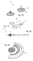
figures 1 à 5 sont des vues en perspective d'étapes d'assemblage d'un assortiment selon un premier mode de réalisation de l'invention ; - les
figures 6 à 8 sont des vues en coupe d'étapes d'assemblage d'un assortiment selon un premier mode de réalisation de l'invention ; - la
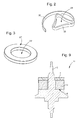
figure 9 est une alternative d'assemblage de lafigure 8 ; - les
figures 10 à 12 sont des vues en coupe d'étapes d'assemblage d'un assortiment selon une variante desfigures 6 à 8 ; - les
figures 13 et 14 sont des vues en coupe d'étapes d'assemblage d'un assortiment selon un deuxième mode de réalisation de l'invention ; - la
figure 15 est une alternative d'assemblage de lafigure 14 ; - la
figure 16 est une vue en coupe d'étapes d'un assortiment selon une variante de lafigure 14 ; - la
figure 17 est une vue éclatée d'un mouvement horloger selon l'invention ; - la
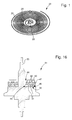
figure 18 est une vue partielle d'un rouage selon l'invention ; - la
figure 19 est une vue d'une ancre selon l'invention ; - la
figure 20 est une vue d'une tige de remontoir selon l'invention ; - la
figure 21 est une vue d'une masse oscillante selon l'invention.
- the
Figures 1 to 5 are perspective views of assembly steps of an assortment according to a first embodiment of the invention; - the
Figures 6 to 8 are sectional views of assembly steps of an assortment according to a first embodiment of the invention; - the
figure 9 is an alternative assembly of thefigure 8 ; - the
Figures 10 to 12 are sectional views of assembly steps of an assortment according to a variant ofFigures 6 to 8 ; - the
Figures 13 and 14 are sectional views of assembly steps of an assortment according to a second embodiment of the invention; - the
figure 15 is an alternative assembly of thefigure 14 ; - the
figure 16 is a sectional view of steps of an assortment according to a variant of thefigure 14 ; - the
figure 17 is an exploded view of a watch movement according to the invention; - the
figure 18 is a partial view of a cog according to the invention; - the
figure 19 is a view of an anchor according to the invention; - the
figure 20 is a view of a winding stem according to the invention; - the
figure 21 is a view of an oscillating mass according to the invention.
L'invention se rapporte à un assortiment horloger pour une pièce d'horlogerie utilisant un alliage métallique amorphe et notamment un tel assortiment comportant une pièce horlogère dont le matériau ne comporte pas de domaine plastique utilisable, c'est-à-dire avec un domaine plastique très restreint.The invention relates to a watchmaking assortment for a timepiece using an amorphous metal alloy and in particular such an assortment comprising a watchmaking part whose material does not comprise a usable plastic domain, that is to say with a field very limited plastic.
Un tel matériau peut être de manière nullement limitative du silicium monocristallin dopé ou non, du silicium polycristallin dopé ou non, de l'oxyde de silicium, du quartz, de la silice, du corindon monocristallin, du corindon polycristallin, de l'alumine, du rubis, du nitrure de silicium ou du carbure de silicium. Ce matériau pouvant comporter au moins un revêtement partiel d'oxyde de silicium, de nitrure de silicium, de carbure de silicium ou d'un allotrope du carbone. Bien entendu, d'autres types de matériau tels que d'autres céramiques peuvent envisagés tout comme d'autres types de revêtement.Such a material may be in no way limiting doped or un doped monocrystalline silicon, polycrystalline silicon doped or not, silicon oxide, quartz, silica, monocrystalline corundum, polycrystalline corundum, alumina, ruby, silicon nitride or silicon carbide. This material may comprise at least one partial coating of silicon oxide, silicon nitride, silicon carbide or a carbon allotrope. Of course, other types of material such as other ceramics may be considered as other types of coating.
Selon un premier mode de réalisation de l'invention illustré notamment aux
On comprend avantageusement selon l'invention, qu'uniquement par recouvrement partiel de la pièce horlogère 3, 13 par l'élément de fixation 7, 17, il n'est plus nécessaire de mettre en oeuvre un collage. En effet, sous certaines conditions expliquées ci-dessous, un alliage métallique au moins partiellement amorphe autorise de manière avantageuse à prendre la forme de n'importe quel objet à la manière d'une pâte déformée. Cette malléabilité de l'élément de fixation 7 conjuguée à la rugosité de surface de la pièce horlogère 3, 13 offre une adhérence suffisante pour une application horlogère.It is advantageously understood according to the invention, only by partial recovery of the
Avantageusement selon l'invention, selon une première alternative du premier mode de réalisation, l'assortiment 1 comporte un élément de fixation 7 qui est monté contre une portée 6 de l'axe 5 comme illustré à la
Selon une deuxième alternative du premier mode de réalisation, l'assortiment 11 comporte au contraire une pièce horlogère 3 qui est montée contre une portée 6 de l'axe 5 comme illustré à la
De manière préférée selon l'invention, il a été trouvé qu'au moins un cinquième de la hauteur de la pièce horlogère 3, 13 recouvert par l'élément de fixation 7, 17 permet une bonne solidarisation lorsque la hauteur de la pièce horlogère 3, 13 est comprise entre 100 et 500 µm. De plus, il a également été trouvé préférentiellement qu'une épaisseur minimale de 50 µm de l'élément de fixation 7, 17 au niveau du trou 8, 18 ne recouvrant pas la pièce horlogère 3, 13 permet un bon chassage.In a preferred manner according to the invention, it has been found that at least one fifth of the height of the
Préférentiellement selon l'invention, l'élément de fixation 7, 17 est un alliage à base magnésium, à base titane, à base zirconium, à base fer, à base cobalt, à base or, à base palladium ou à base platine. Plus précisément, un élément de fixation 7, 17 formé par un alliage à structure au moins partiellement amorphe du type ZrTiCuNiBe, PdCuNiP ou PtCuNiP ont chacun donné satisfaction.Preferably, according to the invention, the fixing
Selon une variante du premier mode de réalisation visible à la
Dans l'exemple illustré à la
On comprend immédiatement que l'assortiment horloger 1, 11, 21 peut ainsi former tout ou partie d'un rouage 101, d'un système d'échappement 103 ou d'un résonateur 105. Plus précisément, la pièce horlogère 3, 13 peut ainsi former une roue 102, un pignon 104, 112, une masse oscillante 106, un ressort (tel par exemple qu'un ressort de barillet), une roue d'échappement 107, une baguette 108 d'ancre 109, un dard 110 d'ancre 109, une fourchette 111 d'ancre 109, un balancier 113, un plateau (tel par exemple qu'un double plateau tenant une cheville) ou un spiral 115.It is immediately understood that the
Selon un deuxième mode de réalisation de l'invention illustré notamment aux
On comprend avantageusement selon l'invention, qu'uniquement par recouvrement partiel de la pièce horlogère 33, 43 et de l'organe de chassage 39, 49 par l'élément de fixation 37, 47, il n'est plus nécessaire de mettre en oeuvre un collage. En effet, sous certaines conditions expliquées ci-dessous, un alliage métallique au moins partiellement amorphe autorise de manière avantageuse à prendre la forme de n'importe quel objet à la manière d'une pâte déformée. Cette malléabilité de l'élément de fixation 37, 47 conjuguée à la rugosité de surface de la pièce horlogère 33, 43 et de l'organe de chassage 39, 49 offre une adhérence suffisante pour une application horlogère.It is advantageously understood according to the invention, that only by partially covering the
Avantageusement selon l'invention, selon une première alternative du deuxième mode de réalisation, l'assortiment 31 comporte un organe de chassage 39 qui est monté contre une portée 36 de l'axe 35 comme illustré à la
Selon une deuxième alternative du deuxième mode de réalisation, l'assortiment 41 comporte au contraire une pièce horlogère 33 qui est montée contre une portée 36 de l'axe 35 comme illustré à la
De manière préférée selon l'invention, il a été trouvé qu'au moins un cinquième de la hauteur de la pièce horlogère 33, 43 et de la hauteur de l'organe de chassage 39, 49 recouvert par l'élément de fixation 37, 47 permet une bonne solidarisation lorsque la hauteur de la pièce horlogère 33, 43 et/ou la hauteur de l'organe de chassage 39, 49 sont chacune comprise entre 100 et 500 µm.In a preferred manner according to the invention, it has been found that at least one fifth of the height of the
Préférentiellement selon l'invention, l'élément de fixation 37, 47 est un alliage à base magnésium, à base titane, à base zirconium, à base fer, à base cobalt, à base or, à base palladium ou à base platine. Plus précisément, un élément de fixation 37, 47 formé par un alliage à structure au moins partiellement amorphe du type ZrTiCuNiBe, PdCuNiP ou PtCuNiP ont chacun donné satisfaction.Preferably, according to the invention, the fixing
De plus, l'organe de chassage 39, 49 est, de manière préférée, un métal ou un alliage métallique tel qu'un acier inoxydable, un laiton ou un maillechort.In addition, the driving
Selon une variante du deuxième mode de réalisation visible à la
Dans l'exemple illustré à la
On comprend immédiatement que l'assortiment horloger 31, 41, 51 peut ainsi former tout ou partie d'un rouage 101, d'un système d'échappement 103 ou d'un résonateur 105. Plus précisément, la pièce horlogère 33, 43 peut ainsi former une roue 102, un pignon 104, 112, une masse oscillante 106, un ressort (tel par exemple qu'un ressort de barillet), une roue d'échappement 107, une baguette 108 d'ancre 109, un dard 110 d'ancre 109, une fourchette 111 d'ancre 109, un balancier 113, un plateau (tel par exemple qu'un double plateau tenant une cheville) ou un spiral 115.It is immediately understood that the
Des procédés d'assemblage selon l'invention d'un assortiment horloger vont maintenant être expliqués en relation avec les
Comme illustré aux
De plus, à la
Toutefois, la présence d'un trou 8', 28' à ce stade n'est pas indispensable. En effet, alternativement un disque pourrait être utilisé à la place d'un élément de forme sensiblement annulaire. Le trou pourrait alors être formé lorsque le disque est déformé à chaud.However, the presence of a hole 8 ', 28' at this stage is not essential. Indeed, alternatively a disk could be used in place of a substantially annular shaped element. The hole could then be formed when the disc is hot deformed.
Préférentiellement selon l'invention, l'élément de fixation 7', 27' est un alliage à base magnésium, à base titane, à base zirconium, à base fer, à base cobalt, à base or, à base palladium ou à base platine. Plus précisément, un élément de fixation 7', 27' formé par un alliage à structure au moins partiellement amorphe du type ZrTiCuNiBe, PdCuNiP ou PtCuNiP ont chacun donné satisfaction.Preferably, according to the invention, the fastening element 7 ', 27' is a magnesium-base, titanium-based, zirconium-based, iron-based, cobalt-based, gold-based, palladium-based or platinum-based alloy. . More specifically, a fixing element 7 ', 27' formed by an alloy with at least partially amorphous structure of the ZrTiCuNiBe, PdCuNiP or PtCuNiP type have each been satisfactory.
L'élément de fixation 7', 27' peut être formé à partie d'une bande ou d'un fil puis être découpé dedans. Une trempe rapide sur disque (appelé « melt spinning » en anglais) ou une coulée suivie d'une trempe peuvent être envisagées.The fastening element 7 ', 27' can be formed from a strip or wire and then cut into it. A fast hardening on disk (called "melt spinning" in English) or a casting followed by quenching can be envisaged.
Le procédé selon l'invention se poursuit avec la deuxième étape b) destinée à enfoncer partiellement la pièce horlogère 3, 23 dans l'élément de fixation 7', 27' chauffé entre sa température de transition vitreuse Tg et sa température de cristallisation Tx afin de former un ensemble pièce horlogère 3, 23 - élément de fixation 7, 27 comme illustré aux
En effet, l'élément de fixation 7', 27' en alliage métallique au moins partiellement amorphe, quand il est chauffé entre sa température de transition vitreuse Tg et sa température de cristallisation Tx, voit sa viscosité chuter jusqu'à permettre la pièce horlogère 3, 23 à pouvoir être enfoncée par simple poussée. Comme visible aux
Selon une variante du premier mode de réalisation illustrée aux
Dans le but de garantir une géométrie prédéterminée de l'élément de fixation à la fin de l'étape b), un gabarit peut être utilisé pour limiter la déformation de l'élément de fixation 7, 17, 27 selon certaines cotes telles que celle de la section du trou 8, 18, 28 et celle de la paroi périphérique de l'élément de fixation 7, 17, 27, voire, comme expliqué ci-dessus, former le trou 8, 18, 28 dans le disque d'ébauche de l'élément de fixation.In order to guarantee a predetermined geometry of the fixing element at the end of step b), a template can be used to limit the deformation of the
De manière additionnelle au gabarit ou de manière isolée, une entretoise peut être utilisée lors de l'étape b) afin de garantir la profondeur de pénétration de la pièce horlogère 3, 13, 23 dans l'élément de fixation 7, 17, 27. Cette entretoise est par exemple utilisée pour garantir qu'une épaisseur minimale de 50 µm de l'élément de fixation 7, 17, 27 reste après l'étape b), c'est-à-dire, pour la première alternative des
De manière optionnelle, après l'étape b) et avant l'étape c) expliquée ci-dessous, le procédé peut comporter une étape intermédiaire d) destinée à maintenir l'ensemble pièce horlogère 3, 13, 23 - élément de fixation 7, 17, 27 au-dessus de la température de transition vitreuse Tg de l'élément de fixation 7, 17, 27 afin de rendre plus ductile l'élément de fixation 7, 17, 27. En effet, un tel maintien en température permet d'initier une cristallisation notamment au niveau du trou 8, 18, 28 propre à faciliter l'étape finale c) expliquée ci-dessous.Optionally, after step b) and before step c) explained below, the method may comprise an intermediate step d) intended to hold the
Enfin, le procédé se termine avec l'étape c) destinée à chasser un axe 5, 25 dans le trou 8, 18, 28 de l'élément de fixation 7, 17, 27 pour former l'assortiment horloger 1, 11, 21, c'est-à-dire en un ensemble solidaire formé d'un axe 5, 25, d'un élément de fixation 7, 17, 27 et d'une pièce horlogère 3, 13, 23.Finally, the process ends with step c) intended to drive an
Selon une première alternative de l'étape c), l'élément de fixation 7, 17 est plaqué contre la portée 6, 26 de l'axe 5, 25 comme illustré aux
On comprend, avantageusement selon le premier mode de réalisation de l'invention, que la pièce horlogère 3, 13, 23, comportant un ajourage 4, 14, 24 qui s'étend autour du trou 8, 18, 28 de l'élément de fixation 7, 17, 27 en ayant une plus grande section, ne subit qu'une contrainte minimale, voire aucune contrainte, lors de l'étape c), c'est-à-dire que la quasi-totalité, voire la totalité, de la contrainte de chassage exercée lors de l'étape c) sera supportée par l'élément de fixation 7, 17, 27. Cela permet de laisser un interstice, c'est-à-dire une zone sans matière comme visible aux
Selon un deuxième mode de réalisation d'assortiment horloger 31, 41, 51, le procédé selon l'invention comporte une première étape a') destinée à fabriquer une pièce horlogère 33, 43, un élément de fixation en alliage métallique au moins partiellement amorphe et un organe de chassage 39, 49 muni d'un trou 38, 48.According to a second embodiment of
Sans être illustrés, la pièce horlogère 33, 43 et l'élément de fixation peuvent être de forme sensiblement identique à ceux 3, 13, 23, 7', 27' du premier mode de réalisation. On comprend donc que la forme de l'élément de fixation n'a pas une importance primordiale. Préférentiellement selon l'invention, l'organe de chassage 39, 49 est en forme de rondelle et comporte un trou 38, 48 dont la géométrie est importante d'être maîtrisée.Without being illustrated, the
Le procédé selon l'invention se poursuit avec la deuxième étape b') destinée à enfoncer partiellement la pièce horlogère 33, 43 et l'organe de chassage 39, 49 dans l'élément de fixation chauffé entre sa température de transition vitreuse Tg et sa température de cristallisation Tx afin de former un ensemble pièce horlogère 33, 43 - élément de fixation 37, 47 - organe de chassage 39, 49.The method according to the invention continues with the second step b ') intended to partially drive the
En effet, l'élément de fixation en alliage métallique au moins partiellement amorphe, quand il est chauffé entre sa température de transition vitreuse Tg et sa température de cristallisation Tx, voit sa viscosité chuter jusqu'à permettre la pièce horlogère 33, 43 à pourvoir être enfoncée par simple poussée. Comme visible aux
Selon une variante du deuxième mode de réalisation illustrée à la
Dans le but de garantir une géométrie prédéterminée de l'élément de fixation à la fin de l'étape b'), un gabarit peut être utilisé pour limiter la déformation de l'élément de fixation 37, 47 selon certaines cotes telles que celle de la paroi interne et celle de la paroi périphérique de l'élément de fixation 37, 47.In order to guarantee a predetermined geometry of the fixing element at the end of step b '), a template can be used to limit the deformation of the fixing
De manière additionnelle au gabarit ou de manière isolée, une entretoise peut être utilisée lors de l'étape b') afin de garantir la profondeur de pénétration de la pièce horlogère 33, 43 et de l'organe de chassage 39, 49 dans l'élément de fixation 37, 47. Cette entretoise est par exemple utilisée pour garantir qu'une épaisseur minimale de 50 µm de l'élément de fixation 37, 47 entre la pièce horlogère 33, 43 et de l'organe de chassage 39,49.In addition to the template or in isolation, a spacer may be used during step b ') to guarantee the depth of penetration of the
Enfin, le procédé se termine avec l'étape c') destinée à chasser un axe 35 dans le trou 38, 48 de l'organe de chassage 39, 49 pour former l'assortiment horloger 31, 41, 51, c'est-à-dire en un ensemble solidaire formé d'un axe 35, d'un organe de chassage 39, 49, d'un élément de fixation 37, 47 et d'une pièce horlogère 33, 43.Finally, the process ends with step c ') intended to drive an
Selon une première alternative de l'étape c'), l'organe de chassage 39, 49 est plaqué contre la portée 36 de l'axe 35 comme illustré aux
On comprend, avantageusement selon le deuxième mode de réalisation de l'invention, que la pièce horlogère 33, 43, comportant un ajourage 34, 44 qui s'étend autour du trou 38, 48 de l'organe de chassage 39, 49 en ayant une plus grande section et, ne subit aucune contrainte lors de l'étape c'), c'est-à-dire que la totalité de la contrainte de chassage exercée lors de l'étape c') sera supportée par l'organe de chassage 39, 49. Cela permet de laisser un interstice, c'est-à-dire une zone sans matière comme visible aux
En outre, conformément à ces deux modes de réalisation, on comprend, avantageusement selon l'invention, que l'élément de fixation 7, 17, 27, 37, 47 en alliage métallique au moins partiellement amorphe va prendre parfaitement la forme d'une partie de la pièce horlogère 3, 13, 23, 33, 43, et, éventuellement, de l'organe de chassage 39, 49, lui autorisant en combinaison à la rugosité de surface de la pièce horlogère 3, 13, 23, 33, 43 et, éventuellement, de l'organe de chassage 39, 49 à s'y agripper sans qu'il ne soit plus nécessaire de mettre en oeuvre un collage.In addition, according to these two embodiments, it is advantageously understood according to the invention, that the
Bien entendu, la présente invention ne se limite pas à l'exemple illustré mais est susceptible de diverses variantes et modifications qui apparaîtront à l'homme de l'art. En particulier, la géométrie de la pièce horlogère 3, 13, 23, 33, 43 peut différer sans que les avantages de la présente description soient perdus.Of course, the present invention is not limited to the illustrated example but is susceptible of various variations and modifications that will occur to those skilled in the art. In particular, the geometry of the
L'étape c), c') de chassage de l'axe 5, 25, 35 pourrait également se faire à une température supérieure à la température de transition vitreuse Tg de l'alliage métallique au moins partiellement amorphe afin de ramollir légèrement ce dernier pour diminuer les contraintes sur le matériau de la pièce horlogère 3, 13, 23, 33, 43 tout en conservant une bonne tenue. Ainsi, à titre d'exemple, le procédé pourrait comporter une première phase c1) destinée à chauffer l'axe au-dessus de la température de transition vitreuse de l'élément de fixation et une deuxième phase c2) destinée à chasser l'axe dans le trou de l'élément de fixation ou de l'organe de chassage afin d'élever la température de la surface de contact de l'élément de fixation au-dessus de sa température de transition vitreuse dans le but de ramollir localement l'élément de fixation pour diminuer les contraintes sur le matériau de la pièce horlogère tout en conservant une bonne tenue.Step c), c ') of driving the
Ce chauffage faciliterait également la formation d'un trou par le passage de l'axe dans le cas où un disque est utilisé pour former l'élément de fixation lors de l'étape a). Cette configuration permettrait enfin de diminuer les risques de désolidarisation de l'ensemble formé à l'étape b), b').This heating would also facilitate the formation of a hole through the passage of the axis in the case where a disc is used to form the fastener in step a). This configuration would finally reduce the risk of separation of the assembly formed in step b), b ').
Il est également possible de jouer sur la structuration de surface de l'axe 5, 25, 35 afin d'améliorer l'accroche lors de l'étape c), c') de chassage.It is also possible to play on the surface structuring of the
De plus, l'utilisation d'un axe 5, 25, 35 à faible coefficient de dilatation est préférable pour limiter le retrait lors du refroidissement qu'il soit effectué lors de l'étape b), b') ou c), c').In addition, the use of a low coefficient of
Enfin, à la lecture des procédés ci-dessus, on comprend qu'il est possible de former plusieurs ensembles en même temps. Ainsi, à titre d'exemple, les pièces horlogères pourraient être maintenues solidaires de leur plaquette de gravage et les éléments de fixation de leur bande ou de leur fil afin de les monter les unes sur les autres pour l'étape b), b') de solidarisation (appelé « wafer scale assembling » en anglais). De manière similaire, plusieurs ensembles pourraient être chassés sur leur axe respectif lors de la même étape c), c').Finally, upon reading the above methods, it is understood that it is possible to form several sets at the same time. Thus, for example, the watch parts could be held integral with their etching plate and the fastening elements of their band or wire to mount them on each other for step b), b ' ) of solidarity (called "wafer scale assembly" in English). Similarly, several sets could be driven on their respective axis during the same step c), c ').
Claims (38)
Priority Applications (1)
| Application Number | Priority Date | Filing Date | Title |
|---|---|---|---|
| EP15159307.6A EP2930572B1 (en) | 2014-04-07 | 2015-03-17 | Clock set using an amorphous metal alloy |
Applications Claiming Priority (2)
| Application Number | Priority Date | Filing Date | Title |
|---|---|---|---|
| EP14163754.6A EP2930571A1 (en) | 2014-04-07 | 2014-04-07 | Horological ensemble using an amorphous metal alloy |
| EP15159307.6A EP2930572B1 (en) | 2014-04-07 | 2015-03-17 | Clock set using an amorphous metal alloy |
Publications (3)
| Publication Number | Publication Date |
|---|---|
| EP2930572A2 true EP2930572A2 (en) | 2015-10-14 |
| EP2930572A3 EP2930572A3 (en) | 2016-03-30 |
| EP2930572B1 EP2930572B1 (en) | 2018-02-28 |
Family
ID=50439264
Family Applications (2)
| Application Number | Title | Priority Date | Filing Date |
|---|---|---|---|
| EP14163754.6A Withdrawn EP2930571A1 (en) | 2014-04-07 | 2014-04-07 | Horological ensemble using an amorphous metal alloy |
| EP15159307.6A Active EP2930572B1 (en) | 2014-04-07 | 2015-03-17 | Clock set using an amorphous metal alloy |
Family Applications Before (1)
| Application Number | Title | Priority Date | Filing Date |
|---|---|---|---|
| EP14163754.6A Withdrawn EP2930571A1 (en) | 2014-04-07 | 2014-04-07 | Horological ensemble using an amorphous metal alloy |
Country Status (6)
| Country | Link |
|---|---|
| US (2) | US9709954B2 (en) |
| EP (2) | EP2930571A1 (en) |
| JP (1) | JP5945347B2 (en) |
| CN (1) | CN104977838B (en) |
| HK (1) | HK1216120A1 (en) |
| RU (1) | RU2679479C2 (en) |
Cited By (1)
| Publication number | Priority date | Publication date | Assignee | Title |
|---|---|---|---|---|
| EP3182212A1 (en) * | 2015-12-17 | 2017-06-21 | Nivarox-FAR S.A. | Composite part with resilient means under stress |
Families Citing this family (9)
| Publication number | Priority date | Publication date | Assignee | Title |
|---|---|---|---|---|
| EP3067756B1 (en) * | 2015-03-09 | 2017-11-22 | Nivarox-FAR S.A. | Swivel assembly for a timepiece |
| EP3214506B1 (en) * | 2016-03-04 | 2019-01-30 | ETA SA Manufacture Horlogère Suisse | Compact hairspring with constant double cross-section |
| EP3309625B1 (en) * | 2016-10-13 | 2020-07-29 | Nivarox-FAR S.A. | Hairspring intended for being attached by a spring washer |
| JP6853077B2 (en) * | 2017-03-14 | 2021-03-31 | セイコーインスツル株式会社 | Watch parts, movements and watches |
| JP2018155523A (en) * | 2017-03-16 | 2018-10-04 | セイコーインスツル株式会社 | Watch component, movement, and watch |
| JP6876559B2 (en) * | 2017-07-20 | 2021-05-26 | シチズン時計株式会社 | Manufacturing method of barrel car and barrel lid |
| CH714452A2 (en) * | 2017-12-15 | 2019-06-28 | Nivarox Sa | Barrel spring for a watch movement of a timepiece and method of manufacturing such a spring. |
| JP7223613B2 (en) * | 2018-06-12 | 2023-02-16 | セイコーインスツル株式会社 | Watch parts, movements, watches and methods of manufacturing watch parts |
| JP7055085B2 (en) * | 2018-10-05 | 2022-04-15 | シチズン時計株式会社 | Fixed structure of rotating shaft and rotating member |
Family Cites Families (13)
| Publication number | Priority date | Publication date | Assignee | Title |
|---|---|---|---|---|
| CH436134A (en) * | 1965-03-19 | 1967-11-15 | Virola Sa | Method of fixing a watch balance spring to the balance axis |
| CH699147B1 (en) * | 2005-12-22 | 2010-01-29 | Patek Philippe Sa Geneve | Fixing a hard piece of glass or sapphire on a metal stand in a desired axial and angular position by welding, comprises producing a cylindrical hub on one end of a support, and affixing a layer of thin metal hook on a surface of the hub |
| CH699680B1 (en) * | 2008-10-03 | 2014-09-15 | Richemont Int Sa | Device for fixing a fragile movable on a support member. |
| EP2273322B1 (en) * | 2009-07-10 | 2012-05-23 | Chopard Technologies SA | Method for mounting a part on a pivoting element |
| US8926170B2 (en) * | 2010-06-22 | 2015-01-06 | The Swatch Group Research And Development Ltd | Timepiece anti-shock system |
| WO2011161138A1 (en) * | 2010-06-22 | 2011-12-29 | The Swatch Group Research And Development Ltd | Method for regulating the relative position of a first part and a second part of a mechanical assembly |
| WO2012010941A1 (en) * | 2010-07-21 | 2012-01-26 | Rolex S.A. | Watch-making or clock-making component comprising an amorphous metal alloy |
| CN103228805B (en) * | 2010-07-21 | 2015-11-25 | 劳力士有限公司 | amorphous metal alloy |
| CH704016B1 (en) | 2010-10-15 | 2019-01-31 | Eta Sa Mft Horlogere Suisse | Assembly of a part not having a plastic field. |
| CH704256A2 (en) * | 2010-12-22 | 2012-06-29 | Eta Sa Mft Horlogere Suisse | Assembly for assembling e.g. pivoting staff in opening of mobile of timepiece, has intermediate part that is deformed to radially clamp component and to stress deformation units to join together assembly for piece |
| CH704258A2 (en) * | 2010-12-22 | 2012-06-29 | Nivarox Sa | Assembly for assembling pivoting axle in opening of piece e.g. pallet, of timepiece, has intermediate portion that clamps element and radially forces piece elastically so as to secure assembly in non-destructive manner for piece |
| CH704259A2 (en) * | 2010-12-22 | 2012-06-29 | Nivarox Sa | Metal/metal alloy based axially extending unit and plasticless component assembly e.g. steel/steel alloy based pivot pin and balance spring assembly, for timepiece, has deformed part to radially clamp wall for joining component and unit |
| CH706645A1 (en) * | 2012-06-26 | 2013-12-31 | Cornel Marxer | Coupling system for coupling e.g. cog wheel with metal axle, in clockwork field, has plastically deformable material layer interposed between hole and axle and positioned to absorb plastic deformation related to driving operation |
-
2014
- 2014-04-07 EP EP14163754.6A patent/EP2930571A1/en not_active Withdrawn
-
2015
- 2015-03-17 EP EP15159307.6A patent/EP2930572B1/en active Active
- 2015-03-26 US US14/669,127 patent/US9709954B2/en active Active
- 2015-04-02 CN CN201510155052.0A patent/CN104977838B/en active Active
- 2015-04-03 JP JP2015076542A patent/JP5945347B2/en active Active
- 2015-04-06 RU RU2015112606A patent/RU2679479C2/en active
-
2016
- 2016-04-12 HK HK16104142.1A patent/HK1216120A1/en unknown
-
2017
- 2017-03-20 US US15/463,330 patent/US9989921B2/en active Active
Non-Patent Citations (1)
| Title |
|---|
| None |
Cited By (1)
| Publication number | Priority date | Publication date | Assignee | Title |
|---|---|---|---|---|
| EP3182212A1 (en) * | 2015-12-17 | 2017-06-21 | Nivarox-FAR S.A. | Composite part with resilient means under stress |
Also Published As
| Publication number | Publication date |
|---|---|
| EP2930571A1 (en) | 2015-10-14 |
| JP5945347B2 (en) | 2016-07-05 |
| RU2015112606A (en) | 2016-10-27 |
| JP2015200652A (en) | 2015-11-12 |
| CN104977838A (en) | 2015-10-14 |
| RU2679479C2 (en) | 2019-02-11 |
| HK1216120A1 (en) | 2016-10-14 |
| EP2930572A3 (en) | 2016-03-30 |
| US20150286188A1 (en) | 2015-10-08 |
| US9709954B2 (en) | 2017-07-18 |
| US9989921B2 (en) | 2018-06-05 |
| RU2015112606A3 (en) | 2018-12-05 |
| CN104977838B (en) | 2018-09-21 |
| US20170192390A1 (en) | 2017-07-06 |
| EP2930572B1 (en) | 2018-02-28 |
Similar Documents
| Publication | Publication Date | Title |
|---|---|---|
| EP2930572B1 (en) | Clock set using an amorphous metal alloy | |
| EP3182212B1 (en) | Composite part with resilient means under stress | |
| EP2196868B1 (en) | Hairspring with curve elevation made from a silicon-based material | |
| EP3152627B1 (en) | Timepiece component made from welded materials | |
| EP3115852B1 (en) | Timepiece component having a part with improved welding surface | |
| EP2104006A1 (en) | Single-body double spiral and method for manufacturing same | |
| EP3112953B1 (en) | Timepiece component having a part with a decoupled welding surface | |
| EP2860592A1 (en) | Assembly system using a planar resilient locking member | |
| EP2317406A1 (en) | Fixation system of a part without force-fitting or bonding | |
| EP2860591A1 (en) | Assembly system using a conical resilient locking member | |
| EP3267265A2 (en) | Method for producing a clockwork assembly and clockwork assembly thus obtained | |
| EP3112951B1 (en) | Manufacturing method comprising a modified machining step | |
| EP2107433A1 (en) | Method for assembling a part on an axle | |
| EP3112950B1 (en) | Manufacturing method comprising a modified bar turning step | |
| EP2585877B1 (en) | Method for producing a watchmaking component comprising at least two parts | |
| EP3430480A1 (en) | Hand comprising an end part, and mounting method | |
| EP3112955B1 (en) | Method for manufacturing a part comprising a modified browning step | |
| CH709517A2 (en) | watchmaker assortment using a fastener made of amorphous metal alloy. | |
| EP3112952B1 (en) | Manufacturing method comprising a modified mounting step | |
| EP3223085B1 (en) | Device comprising a quick-adjustment spring for a clock movement | |
| CH711923B1 (en) | Process for manufacturing a composite part with elastic means under stress, composite part and watch assortment. | |
| CH707884B1 (en) | Watchmaking spiral made of fragile material. | |
| CH711214A2 (en) | A method of manufacturing a part having a browning step. | |
| CH707126A2 (en) | Solidarizing a first part made of non-metallic material with a second part made of metallic material, comprises assembling first and second parts by intercalating solder between two parts, and heating the assembled parts and solder | |
| CH707883B1 (en) | Exhaust organ for watch movement. |
Legal Events
| Date | Code | Title | Description |
|---|---|---|---|
| PUAI | Public reference made under article 153(3) epc to a published international application that has entered the european phase |
Free format text: ORIGINAL CODE: 0009012 |
|
| AK | Designated contracting states |
Kind code of ref document: A2 Designated state(s): AL AT BE BG CH CY CZ DE DK EE ES FI FR GB GR HR HU IE IS IT LI LT LU LV MC MK MT NL NO PL PT RO RS SE SI SK SM TR |
|
| AX | Request for extension of the european patent |
Extension state: BA ME |
|
| PUAL | Search report despatched |
Free format text: ORIGINAL CODE: 0009013 |
|
| RIC1 | Information provided on ipc code assigned before grant |
Ipc: G04B 13/02 20060101AFI20160211BHEP |
|
| AK | Designated contracting states |
Kind code of ref document: A3 Designated state(s): AL AT BE BG CH CY CZ DE DK EE ES FI FR GB GR HR HU IE IS IT LI LT LU LV MC MK MT NL NO PL PT RO RS SE SI SK SM TR |
|
| AX | Request for extension of the european patent |
Extension state: BA ME |
|
| RIC1 | Information provided on ipc code assigned before grant |
Ipc: G04B 13/02 20060101AFI20160219BHEP |
|
| 17P | Request for examination filed |
Effective date: 20160930 |
|
| RBV | Designated contracting states (corrected) |
Designated state(s): AL AT BE BG CH CY CZ DE DK EE ES FI FR GB GR HR HU IE IS IT LI LT LU LV MC MK MT NL NO PL PT RO RS SE SI SK SM TR |
|
| GRAP | Despatch of communication of intention to grant a patent |
Free format text: ORIGINAL CODE: EPIDOSNIGR1 |
|
| INTG | Intention to grant announced |
Effective date: 20171107 |
|
| GRAS | Grant fee paid |
Free format text: ORIGINAL CODE: EPIDOSNIGR3 |
|
| GRAA | (expected) grant |
Free format text: ORIGINAL CODE: 0009210 |
|
| AK | Designated contracting states |
Kind code of ref document: B1 Designated state(s): AL AT BE BG CH CY CZ DE DK EE ES FI FR GB GR HR HU IE IS IT LI LT LU LV MC MK MT NL NO PL PT RO RS SE SI SK SM TR |
|
| REG | Reference to a national code |
Ref country code: GB Ref legal event code: FG4D Free format text: NOT ENGLISH Ref country code: CH Ref legal event code: EP |
|
| REG | Reference to a national code |
Ref country code: AT Ref legal event code: REF Ref document number: 974786 Country of ref document: AT Kind code of ref document: T Effective date: 20180315 |
|
| REG | Reference to a national code |
Ref country code: IE Ref legal event code: FG4D Free format text: LANGUAGE OF EP DOCUMENT: FRENCH |
|
| REG | Reference to a national code |
Ref country code: DE Ref legal event code: R096 Ref document number: 602015008221 Country of ref document: DE Ref country code: CH Ref legal event code: NV Representative=s name: ICB INGENIEURS CONSEILS EN BREVETS SA, CH |
|
| REG | Reference to a national code |
Ref country code: FR Ref legal event code: PLFP Year of fee payment: 4 |
|
| REG | Reference to a national code |
Ref country code: NL Ref legal event code: MP Effective date: 20180228 |
|
| REG | Reference to a national code |
Ref country code: LT Ref legal event code: MG4D |
|
| REG | Reference to a national code |
Ref country code: AT Ref legal event code: MK05 Ref document number: 974786 Country of ref document: AT Kind code of ref document: T Effective date: 20180228 |
|
| PG25 | Lapsed in a contracting state [announced via postgrant information from national office to epo] |
Ref country code: ES Free format text: LAPSE BECAUSE OF FAILURE TO SUBMIT A TRANSLATION OF THE DESCRIPTION OR TO PAY THE FEE WITHIN THE PRESCRIBED TIME-LIMIT Effective date: 20180228 Ref country code: NL Free format text: LAPSE BECAUSE OF FAILURE TO SUBMIT A TRANSLATION OF THE DESCRIPTION OR TO PAY THE FEE WITHIN THE PRESCRIBED TIME-LIMIT Effective date: 20180228 Ref country code: HR Free format text: LAPSE BECAUSE OF FAILURE TO SUBMIT A TRANSLATION OF THE DESCRIPTION OR TO PAY THE FEE WITHIN THE PRESCRIBED TIME-LIMIT Effective date: 20180228 Ref country code: LT Free format text: LAPSE BECAUSE OF FAILURE TO SUBMIT A TRANSLATION OF THE DESCRIPTION OR TO PAY THE FEE WITHIN THE PRESCRIBED TIME-LIMIT Effective date: 20180228 Ref country code: FI Free format text: LAPSE BECAUSE OF FAILURE TO SUBMIT A TRANSLATION OF THE DESCRIPTION OR TO PAY THE FEE WITHIN THE PRESCRIBED TIME-LIMIT Effective date: 20180228 Ref country code: CY Free format text: LAPSE BECAUSE OF FAILURE TO SUBMIT A TRANSLATION OF THE DESCRIPTION OR TO PAY THE FEE WITHIN THE PRESCRIBED TIME-LIMIT Effective date: 20180228 Ref country code: NO Free format text: LAPSE BECAUSE OF FAILURE TO SUBMIT A TRANSLATION OF THE DESCRIPTION OR TO PAY THE FEE WITHIN THE PRESCRIBED TIME-LIMIT Effective date: 20180528 |
|
| PG25 | Lapsed in a contracting state [announced via postgrant information from national office to epo] |
Ref country code: GR Free format text: LAPSE BECAUSE OF FAILURE TO SUBMIT A TRANSLATION OF THE DESCRIPTION OR TO PAY THE FEE WITHIN THE PRESCRIBED TIME-LIMIT Effective date: 20180529 Ref country code: LV Free format text: LAPSE BECAUSE OF FAILURE TO SUBMIT A TRANSLATION OF THE DESCRIPTION OR TO PAY THE FEE WITHIN THE PRESCRIBED TIME-LIMIT Effective date: 20180228 Ref country code: SE Free format text: LAPSE BECAUSE OF FAILURE TO SUBMIT A TRANSLATION OF THE DESCRIPTION OR TO PAY THE FEE WITHIN THE PRESCRIBED TIME-LIMIT Effective date: 20180228 Ref country code: AT Free format text: LAPSE BECAUSE OF FAILURE TO SUBMIT A TRANSLATION OF THE DESCRIPTION OR TO PAY THE FEE WITHIN THE PRESCRIBED TIME-LIMIT Effective date: 20180228 Ref country code: RS Free format text: LAPSE BECAUSE OF FAILURE TO SUBMIT A TRANSLATION OF THE DESCRIPTION OR TO PAY THE FEE WITHIN THE PRESCRIBED TIME-LIMIT Effective date: 20180228 Ref country code: BG Free format text: LAPSE BECAUSE OF FAILURE TO SUBMIT A TRANSLATION OF THE DESCRIPTION OR TO PAY THE FEE WITHIN THE PRESCRIBED TIME-LIMIT Effective date: 20180528 |
|
| PG25 | Lapsed in a contracting state [announced via postgrant information from national office to epo] |
Ref country code: MT Free format text: LAPSE BECAUSE OF FAILURE TO SUBMIT A TRANSLATION OF THE DESCRIPTION OR TO PAY THE FEE WITHIN THE PRESCRIBED TIME-LIMIT Effective date: 20180228 |
|
| PG25 | Lapsed in a contracting state [announced via postgrant information from national office to epo] |
Ref country code: IT Free format text: LAPSE BECAUSE OF FAILURE TO SUBMIT A TRANSLATION OF THE DESCRIPTION OR TO PAY THE FEE WITHIN THE PRESCRIBED TIME-LIMIT Effective date: 20180228 Ref country code: AL Free format text: LAPSE BECAUSE OF FAILURE TO SUBMIT A TRANSLATION OF THE DESCRIPTION OR TO PAY THE FEE WITHIN THE PRESCRIBED TIME-LIMIT Effective date: 20180228 Ref country code: PL Free format text: LAPSE BECAUSE OF FAILURE TO SUBMIT A TRANSLATION OF THE DESCRIPTION OR TO PAY THE FEE WITHIN THE PRESCRIBED TIME-LIMIT Effective date: 20180228 Ref country code: EE Free format text: LAPSE BECAUSE OF FAILURE TO SUBMIT A TRANSLATION OF THE DESCRIPTION OR TO PAY THE FEE WITHIN THE PRESCRIBED TIME-LIMIT Effective date: 20180228 Ref country code: RO Free format text: LAPSE BECAUSE OF FAILURE TO SUBMIT A TRANSLATION OF THE DESCRIPTION OR TO PAY THE FEE WITHIN THE PRESCRIBED TIME-LIMIT Effective date: 20180228 |
|
| REG | Reference to a national code |
Ref country code: DE Ref legal event code: R097 Ref document number: 602015008221 Country of ref document: DE |
|
| PG25 | Lapsed in a contracting state [announced via postgrant information from national office to epo] |
Ref country code: DK Free format text: LAPSE BECAUSE OF FAILURE TO SUBMIT A TRANSLATION OF THE DESCRIPTION OR TO PAY THE FEE WITHIN THE PRESCRIBED TIME-LIMIT Effective date: 20180228 Ref country code: SM Free format text: LAPSE BECAUSE OF FAILURE TO SUBMIT A TRANSLATION OF THE DESCRIPTION OR TO PAY THE FEE WITHIN THE PRESCRIBED TIME-LIMIT Effective date: 20180228 Ref country code: CZ Free format text: LAPSE BECAUSE OF FAILURE TO SUBMIT A TRANSLATION OF THE DESCRIPTION OR TO PAY THE FEE WITHIN THE PRESCRIBED TIME-LIMIT Effective date: 20180228 Ref country code: MC Free format text: LAPSE BECAUSE OF FAILURE TO SUBMIT A TRANSLATION OF THE DESCRIPTION OR TO PAY THE FEE WITHIN THE PRESCRIBED TIME-LIMIT Effective date: 20180228 Ref country code: SK Free format text: LAPSE BECAUSE OF FAILURE TO SUBMIT A TRANSLATION OF THE DESCRIPTION OR TO PAY THE FEE WITHIN THE PRESCRIBED TIME-LIMIT Effective date: 20180228 |
|
| REG | Reference to a national code |
Ref country code: BE Ref legal event code: MM Effective date: 20180331 |
|
| REG | Reference to a national code |
Ref country code: IE Ref legal event code: MM4A |
|
| PG25 | Lapsed in a contracting state [announced via postgrant information from national office to epo] |
Ref country code: LU Free format text: LAPSE BECAUSE OF NON-PAYMENT OF DUE FEES Effective date: 20180317 |
|
| PLBE | No opposition filed within time limit |
Free format text: ORIGINAL CODE: 0009261 |
|
| STAA | Information on the status of an ep patent application or granted ep patent |
Free format text: STATUS: NO OPPOSITION FILED WITHIN TIME LIMIT |
|
| PG25 | Lapsed in a contracting state [announced via postgrant information from national office to epo] |
Ref country code: IE Free format text: LAPSE BECAUSE OF NON-PAYMENT OF DUE FEES Effective date: 20180317 |
|
| 26N | No opposition filed |
Effective date: 20181129 |
|
| PG25 | Lapsed in a contracting state [announced via postgrant information from national office to epo] |
Ref country code: BE Free format text: LAPSE BECAUSE OF NON-PAYMENT OF DUE FEES Effective date: 20180331 Ref country code: SI Free format text: LAPSE BECAUSE OF FAILURE TO SUBMIT A TRANSLATION OF THE DESCRIPTION OR TO PAY THE FEE WITHIN THE PRESCRIBED TIME-LIMIT Effective date: 20180228 |
|
| PG25 | Lapsed in a contracting state [announced via postgrant information from national office to epo] |
Ref country code: TR Free format text: LAPSE BECAUSE OF FAILURE TO SUBMIT A TRANSLATION OF THE DESCRIPTION OR TO PAY THE FEE WITHIN THE PRESCRIBED TIME-LIMIT Effective date: 20180228 |
|
| PG25 | Lapsed in a contracting state [announced via postgrant information from national office to epo] |
Ref country code: PT Free format text: LAPSE BECAUSE OF FAILURE TO SUBMIT A TRANSLATION OF THE DESCRIPTION OR TO PAY THE FEE WITHIN THE PRESCRIBED TIME-LIMIT Effective date: 20180228 |
|
| PG25 | Lapsed in a contracting state [announced via postgrant information from national office to epo] |
Ref country code: MK Free format text: LAPSE BECAUSE OF NON-PAYMENT OF DUE FEES Effective date: 20180228 Ref country code: HU Free format text: LAPSE BECAUSE OF FAILURE TO SUBMIT A TRANSLATION OF THE DESCRIPTION OR TO PAY THE FEE WITHIN THE PRESCRIBED TIME-LIMIT; INVALID AB INITIO Effective date: 20150317 |
|
| PG25 | Lapsed in a contracting state [announced via postgrant information from national office to epo] |
Ref country code: IS Free format text: LAPSE BECAUSE OF FAILURE TO SUBMIT A TRANSLATION OF THE DESCRIPTION OR TO PAY THE FEE WITHIN THE PRESCRIBED TIME-LIMIT Effective date: 20180628 |
|
| PGFP | Annual fee paid to national office [announced via postgrant information from national office to epo] |
Ref country code: FR Payment date: 20230222 Year of fee payment: 9 |
|
| PGFP | Annual fee paid to national office [announced via postgrant information from national office to epo] |
Ref country code: GB Payment date: 20230222 Year of fee payment: 9 Ref country code: DE Payment date: 20230221 Year of fee payment: 9 |
|
| P01 | Opt-out of the competence of the unified patent court (upc) registered |
Effective date: 20230611 |
|
| PGFP | Annual fee paid to national office [announced via postgrant information from national office to epo] |
Ref country code: CH Payment date: 20230402 Year of fee payment: 9 |