EP2930529A1 - Lichttaster - Google Patents
Lichttaster Download PDFInfo
- Publication number
- EP2930529A1 EP2930529A1 EP15157496.9A EP15157496A EP2930529A1 EP 2930529 A1 EP2930529 A1 EP 2930529A1 EP 15157496 A EP15157496 A EP 15157496A EP 2930529 A1 EP2930529 A1 EP 2930529A1
- Authority
- EP
- European Patent Office
- Prior art keywords
- distance
- light
- light sensor
- range
- display
- Prior art date
- Legal status (The legal status is an assumption and is not a legal conclusion. Google has not performed a legal analysis and makes no representation as to the accuracy of the status listed.)
- Granted
Links
Images


Classifications
-
- G—PHYSICS
- G01—MEASURING; TESTING
- G01S—RADIO DIRECTION-FINDING; RADIO NAVIGATION; DETERMINING DISTANCE OR VELOCITY BY USE OF RADIO WAVES; LOCATING OR PRESENCE-DETECTING BY USE OF THE REFLECTION OR RERADIATION OF RADIO WAVES; ANALOGOUS ARRANGEMENTS USING OTHER WAVES
- G01S17/00—Systems using the reflection or reradiation of electromagnetic waves other than radio waves, e.g. lidar systems
- G01S17/02—Systems using the reflection of electromagnetic waves other than radio waves
- G01S17/06—Systems determining position data of a target
- G01S17/46—Indirect determination of position data
- G01S17/48—Active triangulation systems, i.e. using the transmission and reflection of electromagnetic waves other than radio waves
-
- G—PHYSICS
- G01—MEASURING; TESTING
- G01C—MEASURING DISTANCES, LEVELS OR BEARINGS; SURVEYING; NAVIGATION; GYROSCOPIC INSTRUMENTS; PHOTOGRAMMETRY OR VIDEOGRAMMETRY
- G01C3/00—Measuring distances in line of sight; Optical rangefinders
- G01C3/02—Details
- G01C3/06—Use of electric means to obtain final indication
- G01C3/08—Use of electric radiation detectors
-
- G—PHYSICS
- G01—MEASURING; TESTING
- G01S—RADIO DIRECTION-FINDING; RADIO NAVIGATION; DETERMINING DISTANCE OR VELOCITY BY USE OF RADIO WAVES; LOCATING OR PRESENCE-DETECTING BY USE OF THE REFLECTION OR RERADIATION OF RADIO WAVES; ANALOGOUS ARRANGEMENTS USING OTHER WAVES
- G01S17/00—Systems using the reflection or reradiation of electromagnetic waves other than radio waves, e.g. lidar systems
- G01S17/02—Systems using the reflection of electromagnetic waves other than radio waves
- G01S17/04—Systems determining the presence of a target
-
- G—PHYSICS
- G01—MEASURING; TESTING
- G01S—RADIO DIRECTION-FINDING; RADIO NAVIGATION; DETERMINING DISTANCE OR VELOCITY BY USE OF RADIO WAVES; LOCATING OR PRESENCE-DETECTING BY USE OF THE REFLECTION OR RERADIATION OF RADIO WAVES; ANALOGOUS ARRANGEMENTS USING OTHER WAVES
- G01S7/00—Details of systems according to groups G01S13/00, G01S15/00, G01S17/00
- G01S7/48—Details of systems according to groups G01S13/00, G01S15/00, G01S17/00 of systems according to group G01S17/00
- G01S7/51—Display arrangements
-
- G—PHYSICS
- G01—MEASURING; TESTING
- G01V—GEOPHYSICS; GRAVITATIONAL MEASUREMENTS; DETECTING MASSES OR OBJECTS; TAGS
- G01V8/00—Prospecting or detecting by optical means
- G01V8/10—Detecting, e.g. by using light barriers
- G01V8/12—Detecting, e.g. by using light barriers using one transmitter and one receiver
-
- H—ELECTRICITY
- H03—ELECTRONIC CIRCUITRY
- H03K—PULSE TECHNIQUE
- H03K17/00—Electronic switching or gating, i.e. not by contact-making and –breaking
- H03K17/94—Electronic switching or gating, i.e. not by contact-making and –breaking characterised by the way in which the control signals are generated
- H03K17/941—Electronic switching or gating, i.e. not by contact-making and –breaking characterised by the way in which the control signals are generated using an optical detector
-
- G—PHYSICS
- G01—MEASURING; TESTING
- G01S—RADIO DIRECTION-FINDING; RADIO NAVIGATION; DETERMINING DISTANCE OR VELOCITY BY USE OF RADIO WAVES; LOCATING OR PRESENCE-DETECTING BY USE OF THE REFLECTION OR RERADIATION OF RADIO WAVES; ANALOGOUS ARRANGEMENTS USING OTHER WAVES
- G01S17/00—Systems using the reflection or reradiation of electromagnetic waves other than radio waves, e.g. lidar systems
- G01S17/02—Systems using the reflection of electromagnetic waves other than radio waves
- G01S17/06—Systems determining position data of a target
- G01S17/08—Systems determining position data of a target for measuring distance only
-
- H—ELECTRICITY
- H03—ELECTRONIC CIRCUITRY
- H03K—PULSE TECHNIQUE
- H03K2217/00—Indexing scheme related to electronic switching or gating, i.e. not by contact-making or -breaking covered by H03K17/00
- H03K2217/94—Indexing scheme related to electronic switching or gating, i.e. not by contact-making or -breaking covered by H03K17/00 characterised by the way in which the control signal is generated
- H03K2217/941—Indexing scheme related to electronic switching or gating, i.e. not by contact-making or -breaking covered by H03K17/00 characterised by the way in which the control signal is generated using an optical detector
- H03K2217/94102—Indexing scheme related to electronic switching or gating, i.e. not by contact-making or -breaking covered by H03K17/00 characterised by the way in which the control signal is generated using an optical detector characterised by the type of activation
- H03K2217/94108—Indexing scheme related to electronic switching or gating, i.e. not by contact-making or -breaking covered by H03K17/00 characterised by the way in which the control signal is generated using an optical detector characterised by the type of activation making use of reflection
Definitions
- the invention relates to a light scanner with background suppression according to the preamble of claim 1.
- the setting of the maximum switching distance takes place either with a potentiometer, a teach button, externally by a teach line or by means of a display.
- the set detection distance can be displayed on a display, for example by distances in mm or by indicating whether a threshold value is under or exceeded. If an object is outside the respective detection range, then this is not signaled additionally.
- the user When setting the scanning distance, the user does not receive any immediate feedback at the sensor as to whether the required minimum distance (critical distance range) between scanning distance and background is maintained.
- This minimum distance is necessary because on the one hand objects within the range are to be reliably detected and on the other hand objects that are located in the background should be reliably hidden.
- the required minimum distance between the set detection distance and the background can only be taken from the documentation (data sheet, operating instructions) for the light sensor and must be measured on site.
- the light sensor with background suppression comprises a light transmitter, a light receiver, an evaluation unit for determining the distance between the light sensor and an object in the detection range of the light sensor, an adjustment for setting a detection range within which an object is to be detected, wherein set between detection range and background a critical distance range is defined as a function of the set scanning distance, a signal output for outputting a signal when an object is detected within the set scanning distance, and a display unit for indicating whether an object is within the scanning distance, wherein the display unit has at least two display areas , wherein the first display area is formed such that the set scanning distance in relation to a maximum detection range of the light button is displayed and the second display area indicates when an object is in the crit is located in the distance range.
- the user receives a feedback during operation, if there are objects in the critical distance range, which could interfere with a safe detection. Namely, if an object between the set scanning distance and the background is detected, then this is signaled in the second display area. The object to be detected is then out of range and it is in the critical distance range and could interfere with the safe detection. As a result, it can be determined during operation on the display unit, in which distance range an object is detected.
- the invention advantageously provides a continuous indication of whether the objects to be detected are within the set tactile range or in one of the other ranges.
- it can be detected whether undesired objects that are not to be detected are in the critical distance range.
- the invention allows the user a simple and immediate feedback or information on the light sensor on the quality of the set detection range and the detection conditions.
- the expense for external evaluation devices or the measurement with the aid of the documentation of the light scanner is eliminated.
- a third display area is provided in which it can be displayed whether a detected object is located in the background.
- the distance of a detected object within the set detection range in the first display area is qualitatively displayable, so that already with regard to the display, the user has an idea of the approximate position of the object within the detection distance.
- the first display area consists of several LEDs, with an activated part of the LEDs indicating the set detection distance.
- the set working range of the light button in relation to the maximum working range (maximum detection distance) in a simple manner recognizable.
- the distance of the object within the set detection range can be easily indicated by extinguishing one of the activated LEDs associated with the removal of the object. This applies both to the initial setting of the scanning distance (commissioning) and during operation.
- a setting mode for setting the scanning range can be activated, for example by means of a start button or a start command.
- An end of the setting mode is automatically detected by the evaluation unit, if the setting element has not been operated for a predetermined time. This is very user-friendly and facilitates the usability.
- the display unit is annular and the display areas form portions of the ring.
- Such a display is also space-saving, so that it can be used even in small sizes.
- the adjustment is designed as a rotary potentiometer, which is located inside the ring.
- a single teach or double teach button can be provided.
- the light scanner can be designed as Triangulationslichttaster. Triangulation probes are known, have proven themselves and are quite inexpensive to produce. Alternatively, other technologies for distance measurement can be used. Thus, the light sensor could also be designed as a TOF button (time-of-flight), the light transmitter then emitting modulated light and the evaluation unit determining the distance via a determination of the light transit time.
- TOF button time-of-flight
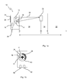
- An in Fig. 1 illustrated inventive light scanner 10 includes a light emitter 12 and a light receiver 14, which are connected to an evaluation unit 16.
- the light scanner 10 in this embodiment is designed as a triangulation light, wherein in the evaluation the position of the impact point 18 of an object 20 in the detection area reflected light beam 22 of the light emitter 12 is detected on the light receiver 14 and the position d the distance between the light scanner 10 and Object 20 is determined.
- the light scanner 10 has a display unit 24 and at least one adjustment element 26. With the adjusting element 26 a scanning distance T is adjustable.
- the scanning distance T is the distance to which the object 20 is to be detected and thus defines a scanning range 30.
- the light scanner 10 gives a switching signal to his Exit 28 off.
- the background 32 is the area having a distance d greater than H.
- the background 32 in which objects are safely hidden, therefore has a distance HT from the touch area 30, in which an object 20 is to be reliably detected.
- This area between set scanning distance T and background is a critical distance range 34. There should be no object, because then no clear assignment to the touch area 30 or 32 background is ensured.
- the display unit 24 is circular and comprises three display areas 40, 42 and 44, which are each formed in a circular arc and are preferably formed from LED elements.
- the display unit can also be designed in the form of a so-called "electronic paper" (colored or black / white).
- the display areas correspond to the distance areas, with the first display area 40 corresponding to the touch area 30, the second display area to the critical distance area 34, and the third display area 44 to the background.
- the set scanning distance T can be displayed in relation to a maximum settable scanning range of the light scanner 10. This is in Fig. 1b recognizable.
- the checkered area of the first display area 40 is intended to represent illumination, preferably by activated LED elements.
- the extent of this luminous area represents the set scanning distance T in relation to the maximum settable scanning distance, which is represented by the entire first display area.
- the display limit would be the maximum possible scanning distance.
- the set scanning distance T is about half of the maximum scanning range.
- the third display area 44 indicates when an object 20 is in the background, ie at a distance greater than H.
- the adjustment member 26 is positioned in the center of the circular display unit 24 and includes a rotary potentiometer, e.g. can be operated by means of a Phillips screwdriver.
- the adjusting element 26 is used to set the scanning distance T, after previously a setting mode, for example by means of a start button, not shown, or a start command has been activated. An end of the adjustment mode is automatically detected by the evaluation unit 16 if the adjustment member 26 has not been operated for a predetermined time.
- the display unit 24 could also be bar-shaped, so that the individual display areas 40, 42, 44 are each formed as a display bar.
- the functions of the display bars are the same as in the first embodiment.
- the display unit 24 could also be designed in the form of a so-called “electronic paper", with display areas 40, 42, 44 as in the aforementioned embodiments.
- the set detection range can be displayed in an additional display 54.
- the display can display the digital scanning distance as a digital display or as "electronic paper” in mm or in inches.
- the display areas may have different colors.
- the first display area 40 could be represented by green LEDs (ok function, scan distance set), the second display area 42 by yellow (object in the critical distance range), and the third display area 44 by blue or white (background object).
- two more indicator LEDs 50 and 52 may be provided, with LED 50 indicating the status of the signal output 28 and the LED 52 indicating whether operating voltage is present.
Landscapes
- Physics & Mathematics (AREA)
- Engineering & Computer Science (AREA)
- Electromagnetism (AREA)
- General Physics & Mathematics (AREA)
- Remote Sensing (AREA)
- Radar, Positioning & Navigation (AREA)
- Computer Networks & Wireless Communication (AREA)
- Life Sciences & Earth Sciences (AREA)
- General Life Sciences & Earth Sciences (AREA)
- Geophysics (AREA)
- Geophysics And Detection Of Objects (AREA)
- Length Measuring Devices By Optical Means (AREA)
- Measurement Of Optical Distance (AREA)
Abstract
Description
- Die Erfindung betrifft einen Lichttaster mit Hintergrundausblendung nach dem Oberbegriff des Anspruchs 1.
- Bei derartigen Lichttastern erfolgt die Einstellung des maximalen Schaltabstandes (Tastweite) entweder mit einem Potentiometer, einer Teach-Taste, extern durch eine Teach-Leitung oder mittels Displayanzeige. Die eingestellte Tastweite kann an einer Anzeige angezeigt werden, beispielsweise durch Abstandsangaben in mm oder durch Anzeigen, ob ein Schwellwert unter- oder überschritten ist. Wenn ein Objekt außerhalb der jeweiligen Tastweite liegt, dann wird dies nicht zusätzlich signalisiert.
- Bei der Tastweiteneinstellung erhält der Anwender keine unmittelbare Rückmeldung am Sensor, ob die erforderliche Mindestdistanz (kritischer Abstandsbereich) zwischen Tastweite und Hintergrund eingehalten wird. Diese Mindestdistanz ist notwendig, weil einerseits Objekte innerhalb der Tastweite sicher erkannt werden sollen und andererseits Objekte, die sich im Hintergrund befinden, zuverlässig ausgeblendet werden sollen. Der erforderliche Mindestabstand zwischen der eingestellten Tastweite und dem Hintergrund kann nur aus der Dokumentation (Datenblatt, Betriebsanleitung) zum Lichttaster entnommen werden und muss vor Ort nachgemessen werden.
- Davon ausgehend ist es Aufgabe der Erfindung, einen verbesserten Lichttaster bereitzustellen, mit dem die vorgenannten Nachteile vermieden werden können und insbesondere eine verbesserte Tastweiteneinstellung, Objektdetektionsanzeige und eine verbesserte Berücksichtigung des kritischen Abstandsbereichs möglich ist.
- Diese Aufgabe wird gelöst mit einem Lichttaster mit den Merkmalen des Anspruchs 1.
- Der erfindungsgemäße Lichttaster mit Hintergrundausblendung umfasst einen Lichtsender, einen Lichtempfänger, eine Auswerteeinheit zur Bestimmung des Abstandes zwischen dem Lichttaster und einem Objekt im Erfassungsbereich des Lichttasters, ein Einstellelement zum Einstellen einer Tastweite, innerhalb derer ein Objekt detektiert werden soll, wobei zwischen eingestellter Tastweite und Hintergrund ein kritischer Abstandsbereich in Abhängigkeit von der eingestellten Tastweite definiert ist, einen Signalausgang zum Ausgeben eines Signals, wenn ein Objekt innerhalb der eingestellten Tastweite detektiert wird und eine Anzeigeeinheit zur Anzeige, ob ein Objekt sich innerhalb der Tastweite befindet, wobei die Anzeigeeinheit wenigstens zwei Anzeigebereiche aufweist, wobei der erste Anzeigebereich derart ausgebildet ist, dass die eingestellte Tastweite im Verhältnis zu einer maximalen Tastweite des Lichttasters anzeigbar ist und der zweite Anzeigebereich anzeigt, wenn ein Objekt sich im kritischen Abstandsbereich befindet.
- Dadurch erhält der Anwender bei der Inbetriebnahme eine unmittelbare Rückmeldung am Sensor, ob die Tastweite korrekt eingestellt wurde, oder ob vielleicht die maximale Tastweite überschritten wurde. Auch erhält der Anwender eine Rückmeldung während des Betriebes, ob sich Objekte im kritischen Abstandsbereich befinden, die eine sichere Detektion stören könnten. Wenn nämlich ein Objekt zwischen der eingestellten Tastweite und dem Hintergrund erfasst wird, dann wird dies in dem zweiten Anzeigebereich signalisiert. Das zu detektierende Objekt liegt dann außerhalb der Tastweite und es befindet sich im kritischen Abstandsbereich und könnte die sichere Detektion stören. Dadurch kann während des Betriebs an der Anzeigeeinheit verbessert festgestellt werden, in welchem Abstandsbereich ein Objekt erfasst wird.
- Mit dem erfindungsgemäßen Lichttaster kann bei der Inbetriebnahme die Einhaltung der spezifizierten maximalen Tastweite überprüft werden. Bei Überschreiten wird dies unmittelbar während der Einstellung durch die Anzeigeeinheit signalisiert.
- Im Betrieb erfolgt mit der Erfindung vorteilhafterweise eine kontinuierliche Anzeige, ob die zu erfassenden Objekte sich innerhalb des eingestellten Tastbereiches befinden oder in einem der anderen Bereiche. Insbesondere kann erkannt werden, ob sich unerwünschte Objekte, die nicht detektiert werden sollen, in dem kritischen Abstandsbereich befinden. Es erfolgt eine unmittelbare Rückmeldung der vorgenannten Situationen an den Anwender direkt am Lichttaster und ohne Zuhilfenahme der Dokumentation oder eines externen Auswertegerätes.
- Somit ermöglicht die Erfindung für den Anwender eine einfache und unmittelbare Rückmeldung bzw. Information am Lichttaster über die Qualität der eingestellten Tastweite und den Detektionsbedingungen. Der Aufwand für externe Auswertegeräte oder die Vermessung unter Zuhilfenahme der Dokumentation des Lichttasters entfällt.
- In Weiterbildung der Erfindung ist ein dritter Anzeigebereich vorgesehen ist, in dem anzeigbar ist, ob sich ein erfasstes Objekt im Hintergrund befindet. Damit können die Abstandsbereiche bereits an der Anzeigeeinheit klarer erkannt und visualisiert werden und eine Zuordnung eines Objekts im Erfassungsbereich des Lichttasters kann klar einem Abstandsbereich zugeordnet werden.
- In Weiterbildung der Erfindung ist die Entfernung eines erfassten Objekts innerhalb der eingestellten Tastweite in dem ersten Anzeigebereich qualitativ anzeigbar, so dass bereits mit Blick auf die Anzeige der Anwender eine Vorstellung von der ungefähren Position des Objektes innerhalb der Tastweite hat.
- In vorteilhafter Weise besteht der erste Anzeigebereich aus mehreren LED's, wobei ein aktivierter Teil der LEDs die eingestellte Tastweite angibt. Damit ist der eingestellte Arbeitsbereich des Lichttasters im Verhältnis zum maximalen Arbeitsbereich (maximale Tastweite) in einfacher Weise erkennbar.
- Mit dieser Ausbildung kann die Entfernung des Objekts innerhalb der eingestellten Tastweite durch Erlöschen einer der aktivierten LEDs, die der Entfernung des Objekts zugeordnet ist, in einfacher Weise angezeigt werden. Dies gilt sowohl für die erstmalige Einstellung der Tastweite (Inbetriebnahme) als auch während des Betriebs.
- Mit Vorteil ist ein Einstellmodus zum Einstellen der Tastweite aktivierbar, beispielsweise mittels einer Starttaste oder einem Startbefehl. Ein Ende des Einstellmodus wird durch die Auswerteeinheit automatisch erkannt, wenn das Einstellelement über eine vorbestimmte Zeit nicht betätigt wurde. Das ist sehr bedienerfreundlich und erleichtert die Bedienbarkeit.
- In optisch ansprechender Weise ist die Anzeigeeinheit ringförmig ausgebildet und die Anzeigebereiche bilden Abschnitte des Ringes. Eine solche Anzeige ist zugleich platzsparend, so dass sie auch bei kleinen Baugrößen eingesetzt werden kann.
- In vorteilhafter und platzsparender Weise ist das Einstellelement als Drehpotentiometer ausgebildet, das sich im Inneren des Ringes befindet. Anstelle des Potentiometers kann auch eine Einzel-Teach oder Doppel-Teach-Taste vorgesehen sein.
- Der Lichttaster kann als Triangulationslichttaster ausgebildet sein. Triangulationstaster sind bekannt, haben sich bewährt und sind recht kostengünstig herstellbar. Alternativ können auch andere Technologien zur Entfernungsmessung eingesetzt werden. So könnte der Lichttaster auch als TOF-Taster (Time-Of-Flight) ausgebildet sein, wobei der Lichtsender dann moduliertes Licht aussendet und die Auswerteeinheit die Entfernung über eine Bestimmung der Lichtlaufzeit bestimmt.
- Im Folgenden wird die Erfindung anhand von Ausführungsbeispielen unter Bezugnahme auf die Zeichnung im Einzelnen erläutert. In der Zeichnung zeigen:
- Fig. 1a
- eine schematische Darstellung eines erfindungsgemäßen Lichttasters in einer Anwendungssituation mit einem Objekt in der Tastweite;
- Fig. 1b
- eine Anzeigeeinheit in der Anwendungssituation nach
Fig. 1a ; - Fig. 2a bis 3b
- Darstellungen wie
Fig. 1a bzw. 1 b bei anderen Objektabständen; - Fig. 4 und 5
- Ausführungsformen der Anzeigeeinheit.
- Ein in
Fig. 1 dargestellter erfindungsgemäßer Lichttaster 10 umfasst einen Lichtsender 12 und einen Lichtempfänger 14, die mit einer Auswerteeinheit 16 verbunden sind. Der Lichttaster 10 in diesem Ausführungsbeispiel ist als Triangulationslichttaster ausgebildet, wobei in der Auswerteeinheit die Position des Auftreffpunkts 18 eines an einem Objekt 20 im Erfassungsbereich reflektierten Lichtstrahls 22 des Lichtsenders 12 auf dem Lichtempfänger 14 ermittelt wird und über die Position die Entfernung d zwischen Lichttaster 10 und Objekt 20 bestimmt wird. - Weiter weist der Lichttaster 10 eine Anzeigeeinheit 24 und wenigstens ein Einstellelement 26 auf. Mit dem Einstellelement 26 ist eine Tastweite T einstellbar. Die Tastweite T ist derjenige Abstand, bis zu dem das Objekt 20 detektiert werden soll und definiert somit einen Tastbereich 30. Wenn also das Objekt 20 sich in dem Tastbereich 30 mit einem Abstand d kleiner gleich T befindet, gibt der Lichttaster 10 ein Schaltsignal an seinem Ausgang 28 aus.
- Wenn ein Objekt sich im Hintergrund 32 befindet, soll dieses Objekt ignoriert werden und kein Schaltsignal ausgegeben werden. Der Hintergrund 32 ist derjenige Bereich, der einen Abstand d größer H hat. Der Hintergrund 32, in dem Objekte sicher ausgeblendet werden, hat also von dem Tastbereich 30, in dem ein Objekt 20 sicher erkannt werden soll, einen Abstand H-T. Dieser Bereich zwischen eingestellter Tastweite T und Hintergrund ist ein kritischer Abstandsbereich 34. Dort sollte sich kein Objekt befinden, denn dann ist keine klare Zuordnung zum Tastbereich 30 oder Hintergrund 32 sichergestellt.
- Ein wesentliches Element der Erfindung ist die Anzeigeeinheit 24. In einer ersten Ausführungsform der Erfindung (
Fig. 1a bis 3b ) ist die Anzeigeeinheit 24 kreisförmig ausgebildet und umfasst drei Anzeigebereiche 40, 42 und 44, die jeweils kreisbogenförmig ausgebildet sind und vorzugsweise aus LED-Elementen gebildet sind. Die Anzeigeeinheit kann auch in Form eines sogenannten "electronic paper" (farbig oder schwarz/weiß) ausgeführt sein. - Die Anzeigenbereiche entsprechen den Abstandsbereichen, wobei der erste Anzeigebereich 40 dem Tastbereich 30 entspricht, der zweite Anzeigebereich dem kritischen Abstandsbereich 34 und der dritte Anzeigebereich 44 dem Hintergrund.
- Im ersten Anzeigebereich 40 ist zunächst die eingestellte Tastweite T im Verhältnis zu einer maximal einstellbaren Tastweite des Lichttasters 10 anzeigbar. Dies ist in
Fig. 1b erkennbar. Der karierte Bereich des ersten Anzeigebereichs 40 soll eine Beleuchtung, vorzugsweise durch aktivierte LED-Elemente, darstellen. Die Ausdehnung dieses leuchtenden Bereichs stellt die eingestellte Tastweite T im Verhältnis zur maximal einstellbaren Tastweite, die durch den gesamten ersten Anzeigebereich repräsentiert wird, dar. Bei Bezugsziffer 41 wäre also die Anzeigegrenze der maximal möglichen Tastweite. In dem Beispiel nachFig. 1b beträgt die eingestellte Tastweite T etwa die Hälfte der maximal einstellbaren Tastweite. - Befindet sich jetzt das Objekt 20 innerhalb der eingestellten Tastweite T, wie z.B. in
Fig. 2a dargestellt, dann wird dies im ersten Anzeigebereich 40 durch Erlöschen einer der Entfernung des Objekts 20 zugeordneten LED dargestellt, wie inFig. 2b an der Position 46 zu erkennen ist. Damit ist zumindest eine qualitative Anzeige der Entfernung möglich. - Befindet sich das Objekt 20 im kritischen Abstandsbereich 34 dann wird dies durch Leuchten des zweiten Anzeigebereichs 42 signalisiert, indem die dortige LED oder LEDs aktiviert werden.
- Im dritten Anzeigebereich 44 wird schließlich angezeigt, wenn ein Objekt 20 sich im Hintergrund befindet, also in einem Abstand größer H.
- In diesen Ausführungsbeispielen ist das Einstellelement 26 in der Mitte der kreisförmigen Anzeigeeinheit 24 positioniert und umfasst einen Drehpotentiometer, der z.B. mittels eines Kreuzschlitz-Schraubendrehers betätigt werden kann. Das Einstellelement 26 dient zum Einstellen der Tastweite T, nachdem zuvor ein Einstellmodus, beispielsweise mittels einer nicht dargestellten Starttaste oder einem Startbefehl, aktiviert wurde. Ein Ende des Einstellmodus wird durch die Auswerteeinheit 16 automatisch erkannt, wenn das Einstellelement 26 über eine vorbestimmte Zeit nicht betätigt wurde.
- In einer alternativen, in
Fig. 4 dargestellten Ausführungsform, könnte die Anzeigeeinheit 24 auch balkenförmig ausgebildet sein, so dass die einzelnen Anzeigebereiche 40, 42, 44 jeweils als Anzeigebalken ausgebildet sind. Die Funktionen der Anzeigebalken sind die gleichen wie beim ersten Ausführungsbeispiel. - In einer alternativen, in
Fig. 5 dargestellten Ausführungsform könnte die Anzeigeeinheit 24 auch in Form eines sogenannten "eletronic paper" ausgebildet sein, mit Anzeigebereichen 40, 42, 44 wie in den vorgenannten Ausführungsbeispielen. - In Weiterbildung der Erfindung kann die eingestellte Tastweite in einem zusätzlichen Display 54 angezeigt werden. Das Display kann als digitale Anzeige oder als "electronic paper" die Tastweite digital als Wert in mm oder in inch anzeigen.
- In Weiterbildung der Erfindung können die Anzeigebereiche unterschiedliche Farben haben. So könnte beispielsweise der erste Anzeigebereich 40 durch grüne LEDs repräsentiert werden (Funktion ok, Tastweite eingestellt), der zweite Anzeigebereich 42 durch gelbe (Objekt im kritischen Abstandsbereich) und der dritte Anzeigebereich 44 durch blaue oder weiße (Objekt im Hintergrund).
- Des Weiteren können zwei weitere Anzeige-LED 50 und 52 vorgesehen sein, wobei LED 50 den Status des Signalausgangs 28 angeben könnte und die LED 52 anzeigt, ob Betriebsspannung anliegt.
Claims (12)
- Lichttaster mit Hintergrundausblendung mit- einem Lichtsender,- einem Lichtempfänger,- einer Auswerteeinheit zur Bestimmung des Abstandes zwischen dem Lichttaster und einem Objekt im Erfassungsbereich des Lichttasters,- einem Einstellelement zum Einstellen einer Tastweite, innerhalb derer ein Objekt detektiert werden soll, wobei zwischen eingestellter Tastweite und Hintergrund ein kritischer Abstandsbereich in Abhängigkeit von der eingestellten Tastweite definiert ist,- einem Signalausgang zum Ausgeben eines Signals, wenn ein Objekt innerhalb der eingestellten Tastweite detektiert wird,- einer Anzeigeeinheit zur Anzeige, ob ein Objekt sich innerhalb der Tastweite befindet,dadurch gekennzeichnet,
dass die Anzeigeeinheit wenigstens zwei Anzeigebereiche aufweist, wobei der erste Anzeigebereich derart ausgebildet ist, dass die eingestellte Tastweite im Verhältnis zu einer maximalen Tastweite des Lichttasters anzeigbar ist und der zweite Anzeigebereich anzeigt, wenn ein Objekt sich im kritischen Abstandsbereich befindet. - Lichttaster nach Anspruch 1, dadurch gekennzeichnet, dass ein dritter Anzeigebereich vorgesehen ist, in dem anzeigbar ist, ob sich ein erfasstes Objekt im Hintergrund befindet.
- Lichttaster nach einem der vorhergehenden Ansprüche, dadurch gekennzeichnet, dass die Entfernung eines erfassten Objekts innerhalb der eingestellten Tastweite in dem ersten Anzeigebereich qualitativ anzeigbar ist.
- Lichttaster nach einem der vorhergehenden Ansprüche, dadurch gekennzeichnet, dass der erste Anzeigebereich aus mehreren LED's besteht, wobei ein aktivierter Teil der LEDs die eingestellte Tastweite angibt.
- Lichttaster nach Anspruch 4, dadurch gekennzeichnet, dass die Entfernung des Objekts innerhalb der eingestellten Tastweite durch Erlöschen einer der aktivierten LEDs, die der Entfernung des Objekts zugeordnet ist, anzeigbar ist.
- Lichttaster nach einem der vorhergehenden Ansprüche, dadurch gekennzeichnet, dass ein Einstellmodus zum Einstellen der Tastweite aktivierbar ist und ein Ende des Einstellmodus automatisch durch die Auswerteeinheit erkannt wird, wenn das Einstellelement über eine vorbestimmte Zeit nicht betätigt wurde.
- Lichttaster nach einem der vorhergehenden Ansprüche, dadurch gekennzeichnet, dass die Anzeigeeinheit ringförmig ausgebildet ist und die Anzeigebereiche Abschnitte des Ringes bilden.
- Lichttaster nach einem der vorhergehenden Ansprüche, dadurch gekennzeichnet, dass die Anzeigeeinheit als Balkenanzeige ausgebildet ist.
- Lichttaster nach einem der vorhergehenden Ansprüche, dadurch gekennzeichnet, dass die Anzeigeeinheit ein Display für die eingestellte Tastweite aufweist.
- Lichttaster nach Anspruch 8, dadurch gekennzeichnet, dass das Einstellelement als Drehpotentiometer ausgebildet ist, das sich im Inneren des Ringes befindet.
- Lichttaster nach einem der vorhergehenden Ansprüche, dadurch gekennzeichnet, dass dieser als Triangulationslichttaster ausgebildet ist.
- Lichttaster nach einem der vorhergehenden Ansprüche 1 bis 10, dadurch gekennzeichnet, dass der Lichtsender moduliertes Licht aussendet und die Auswerteeinheit die Entfernung über eine Bestimmung der Lichtlaufzeit bestimmt.
Applications Claiming Priority (1)
| Application Number | Priority Date | Filing Date | Title |
|---|---|---|---|
| DE201410104968 DE102014104968B3 (de) | 2014-04-08 | 2014-04-08 | Lichttaster |
Publications (2)
| Publication Number | Publication Date |
|---|---|
| EP2930529A1 true EP2930529A1 (de) | 2015-10-14 |
| EP2930529B1 EP2930529B1 (de) | 2016-10-26 |
Family
ID=52009263
Family Applications (1)
| Application Number | Title | Priority Date | Filing Date |
|---|---|---|---|
| EP15157496.9A Active EP2930529B1 (de) | 2014-04-08 | 2015-03-04 | Lichttaster |
Country Status (3)
| Country | Link |
|---|---|
| US (1) | US9835725B2 (de) |
| EP (1) | EP2930529B1 (de) |
| DE (1) | DE102014104968B3 (de) |
Families Citing this family (2)
| Publication number | Priority date | Publication date | Assignee | Title |
|---|---|---|---|---|
| DE102014104968B3 (de) | 2014-04-08 | 2014-12-11 | Sick Ag | Lichttaster |
| TWI697846B (zh) | 2018-11-26 | 2020-07-01 | 財團法人工業技術研究院 | 物體辨識方法及其裝置 |
Citations (2)
| Publication number | Priority date | Publication date | Assignee | Title |
|---|---|---|---|---|
| EP1116963A2 (de) * | 2000-01-14 | 2001-07-18 | Keyence Corporation | Photoelektrischer Schalter |
| DE202012102331U1 (de) * | 2012-06-25 | 2013-09-26 | Sick Ag | Lichttaster |
Family Cites Families (5)
| Publication number | Priority date | Publication date | Assignee | Title |
|---|---|---|---|---|
| US4920412A (en) * | 1988-12-22 | 1990-04-24 | Sperry Marine Inc. | Atmospheric obscurant penetrating target observation system with range gating |
| US8451432B2 (en) * | 2005-06-09 | 2013-05-28 | Analog-Modules, Inc. | Laser spot tracking with off-axis angle detection |
| US8004660B2 (en) * | 2009-03-31 | 2011-08-23 | The United States Of America As Represented By The Secretary Of The Navy | Method and system for determination of detection probability of a target object based on vibration |
| DE102010021807B4 (de) * | 2010-05-27 | 2018-03-29 | Sick Ag | Lichttaster in V-Anordnung |
| DE102014104968B3 (de) | 2014-04-08 | 2014-12-11 | Sick Ag | Lichttaster |
-
2014
- 2014-04-08 DE DE201410104968 patent/DE102014104968B3/de active Active
-
2015
- 2015-03-04 EP EP15157496.9A patent/EP2930529B1/de active Active
- 2015-03-26 US US14/669,022 patent/US9835725B2/en active Active
Patent Citations (2)
| Publication number | Priority date | Publication date | Assignee | Title |
|---|---|---|---|---|
| EP1116963A2 (de) * | 2000-01-14 | 2001-07-18 | Keyence Corporation | Photoelektrischer Schalter |
| DE202012102331U1 (de) * | 2012-06-25 | 2013-09-26 | Sick Ag | Lichttaster |
Also Published As
| Publication number | Publication date |
|---|---|
| US20150285914A1 (en) | 2015-10-08 |
| US9835725B2 (en) | 2017-12-05 |
| EP2930529B1 (de) | 2016-10-26 |
| DE102014104968B3 (de) | 2014-12-11 |
Similar Documents
| Publication | Publication Date | Title |
|---|---|---|
| DE3743180C2 (de) | ||
| DE202012102497U1 (de) | Handwerkzeug mit Warnhinweis auf das Drehmoment | |
| EP2612173B1 (de) | Verfahren zur lokalisierung von in einem medium eingeschlossenen objekten, sowie messgerät zur durchführung des verfahrens | |
| DE102016009364B4 (de) | Kopfschutzvorrichtung | |
| DE102014221439A1 (de) | Photoelektrischer Sensor | |
| EP3194197A1 (de) | Anzeige- und bedienvorrichtung, insbesondere für ein kraftfahrzeug, bedienelement und kraftfahrzeug | |
| DE102015215234A1 (de) | Einrichtung zum Absichern eines Sicherheitsbereichs um mindestens eine automatisch arbeitende Maschine | |
| WO2007115706A1 (de) | Farbtemperatur- und farbortsteuerung für eine leuchte | |
| WO2017139817A1 (de) | Steuerungssystem für elektrisch gesteuerte anlagen | |
| EP2930529B1 (de) | Lichttaster | |
| EP3118049B1 (de) | Vorrichtung und verfahren zur unterstützung eines fahrers eines fahrzeugs, insbesondere eines nutzfahrzeugs | |
| EP0007009B1 (de) | Verfahren zum Anzeigen von Stellgrössen zum Steuern einer Rotationsdruckmaschine | |
| DE102007044679B3 (de) | Konfigurationsmittel für Sicherheits-Lichtgitter | |
| DE202014101644U1 (de) | Lichttaster | |
| EP3796356B1 (de) | Fussschalter für medizinische geräte | |
| DE102005013344A1 (de) | Beleuchtungseinrichtung zum Beleuchten mindestens eines Inneneinrichtungsteils eines Kraftfahrzeugs | |
| DE20317976U1 (de) | Sicherheits-Lichtgitter | |
| DE102017118825B4 (de) | Sensor und Verfahren zum Betrieb eines solchen Sensors | |
| DE19851505C2 (de) | Schaltelement | |
| DE10359561B4 (de) | Bedienelement für ein Haushaltsgerät | |
| DE102015216898B4 (de) | Sensoreinrichtung zur Überwachung eines Sensorbereichs und Verfahren zum Umschalten zwischen zwei Betriebsmodi | |
| EP0242631A2 (de) | Analog anzeigendes Messinstrument mit zweifarbig lichtemittierenden Dioden | |
| EP2296077B1 (de) | Verfahren zum Einstellen von Betriebsparametern eines Sensors und Sensor zum Nachweis einer physikalischen Messgröße | |
| DE2431119B2 (de) | Anordnung zur Anzeige der Stellung eines Stellgliedes | |
| EP3596361A1 (de) | Einrichtung zum erfassen von betriebszuständen in einem automatischen schaltgetriebe |
Legal Events
| Date | Code | Title | Description |
|---|---|---|---|
| PUAI | Public reference made under article 153(3) epc to a published international application that has entered the european phase |
Free format text: ORIGINAL CODE: 0009012 |
|
| AK | Designated contracting states |
Kind code of ref document: A1 Designated state(s): AL AT BE BG CH CY CZ DE DK EE ES FI FR GB GR HR HU IE IS IT LI LT LU LV MC MK MT NL NO PL PT RO RS SE SI SK SM TR |
|
| AX | Request for extension of the european patent |
Extension state: BA ME |
|
| 17P | Request for examination filed |
Effective date: 20160324 |
|
| RBV | Designated contracting states (corrected) |
Designated state(s): AL AT BE BG CH CY CZ DE DK EE ES FI FR GB GR HR HU IE IS IT LI LT LU LV MC MK MT NL NO PL PT RO RS SE SI SK SM TR |
|
| GRAP | Despatch of communication of intention to grant a patent |
Free format text: ORIGINAL CODE: EPIDOSNIGR1 |
|
| RIC1 | Information provided on ipc code assigned before grant |
Ipc: G01S 7/51 20060101AFI20160615BHEP Ipc: G01S 17/48 20060101ALI20160615BHEP Ipc: G01S 17/02 20060101ALI20160615BHEP Ipc: G01C 3/08 20060101ALI20160615BHEP Ipc: G01V 8/12 20060101ALI20160615BHEP Ipc: H03K 17/94 20060101ALI20160615BHEP Ipc: G01S 17/08 20060101ALN20160615BHEP |
|
| INTG | Intention to grant announced |
Effective date: 20160712 |
|
| GRAS | Grant fee paid |
Free format text: ORIGINAL CODE: EPIDOSNIGR3 |
|
| GRAA | (expected) grant |
Free format text: ORIGINAL CODE: 0009210 |
|
| AK | Designated contracting states |
Kind code of ref document: B1 Designated state(s): AL AT BE BG CH CY CZ DE DK EE ES FI FR GB GR HR HU IE IS IT LI LT LU LV MC MK MT NL NO PL PT RO RS SE SI SK SM TR |
|
| REG | Reference to a national code |
Ref country code: GB Ref legal event code: FG4D Free format text: NOT ENGLISH |
|
| REG | Reference to a national code |
Ref country code: CH Ref legal event code: EP |
|
| REG | Reference to a national code |
Ref country code: AT Ref legal event code: REF Ref document number: 840403 Country of ref document: AT Kind code of ref document: T Effective date: 20161115 |
|
| REG | Reference to a national code |
Ref country code: IE Ref legal event code: FG4D Free format text: LANGUAGE OF EP DOCUMENT: GERMAN |
|
| REG | Reference to a national code |
Ref country code: DE Ref legal event code: R096 Ref document number: 502015000253 Country of ref document: DE |
|
| REG | Reference to a national code |
Ref country code: LT Ref legal event code: MG4D |
|
| PG25 | Lapsed in a contracting state [announced via postgrant information from national office to epo] |
Ref country code: LV Free format text: LAPSE BECAUSE OF FAILURE TO SUBMIT A TRANSLATION OF THE DESCRIPTION OR TO PAY THE FEE WITHIN THE PRESCRIBED TIME-LIMIT Effective date: 20161026 |
|
| REG | Reference to a national code |
Ref country code: NL Ref legal event code: MP Effective date: 20161026 |
|
| REG | Reference to a national code |
Ref country code: FR Ref legal event code: PLFP Year of fee payment: 3 |
|
| PG25 | Lapsed in a contracting state [announced via postgrant information from national office to epo] |
Ref country code: SE Free format text: LAPSE BECAUSE OF FAILURE TO SUBMIT A TRANSLATION OF THE DESCRIPTION OR TO PAY THE FEE WITHIN THE PRESCRIBED TIME-LIMIT Effective date: 20161026 Ref country code: GR Free format text: LAPSE BECAUSE OF FAILURE TO SUBMIT A TRANSLATION OF THE DESCRIPTION OR TO PAY THE FEE WITHIN THE PRESCRIBED TIME-LIMIT Effective date: 20170127 Ref country code: LT Free format text: LAPSE BECAUSE OF FAILURE TO SUBMIT A TRANSLATION OF THE DESCRIPTION OR TO PAY THE FEE WITHIN THE PRESCRIBED TIME-LIMIT Effective date: 20161026 Ref country code: NO Free format text: LAPSE BECAUSE OF FAILURE TO SUBMIT A TRANSLATION OF THE DESCRIPTION OR TO PAY THE FEE WITHIN THE PRESCRIBED TIME-LIMIT Effective date: 20170126 |
|
| PG25 | Lapsed in a contracting state [announced via postgrant information from national office to epo] |
Ref country code: RS Free format text: LAPSE BECAUSE OF FAILURE TO SUBMIT A TRANSLATION OF THE DESCRIPTION OR TO PAY THE FEE WITHIN THE PRESCRIBED TIME-LIMIT Effective date: 20161026 Ref country code: FI Free format text: LAPSE BECAUSE OF FAILURE TO SUBMIT A TRANSLATION OF THE DESCRIPTION OR TO PAY THE FEE WITHIN THE PRESCRIBED TIME-LIMIT Effective date: 20161026 Ref country code: ES Free format text: LAPSE BECAUSE OF FAILURE TO SUBMIT A TRANSLATION OF THE DESCRIPTION OR TO PAY THE FEE WITHIN THE PRESCRIBED TIME-LIMIT Effective date: 20161026 Ref country code: PL Free format text: LAPSE BECAUSE OF FAILURE TO SUBMIT A TRANSLATION OF THE DESCRIPTION OR TO PAY THE FEE WITHIN THE PRESCRIBED TIME-LIMIT Effective date: 20161026 Ref country code: PT Free format text: LAPSE BECAUSE OF FAILURE TO SUBMIT A TRANSLATION OF THE DESCRIPTION OR TO PAY THE FEE WITHIN THE PRESCRIBED TIME-LIMIT Effective date: 20170227 Ref country code: NL Free format text: LAPSE BECAUSE OF FAILURE TO SUBMIT A TRANSLATION OF THE DESCRIPTION OR TO PAY THE FEE WITHIN THE PRESCRIBED TIME-LIMIT Effective date: 20161026 Ref country code: HR Free format text: LAPSE BECAUSE OF FAILURE TO SUBMIT A TRANSLATION OF THE DESCRIPTION OR TO PAY THE FEE WITHIN THE PRESCRIBED TIME-LIMIT Effective date: 20161026 Ref country code: IS Free format text: LAPSE BECAUSE OF FAILURE TO SUBMIT A TRANSLATION OF THE DESCRIPTION OR TO PAY THE FEE WITHIN THE PRESCRIBED TIME-LIMIT Effective date: 20170226 |
|
| REG | Reference to a national code |
Ref country code: DE Ref legal event code: R097 Ref document number: 502015000253 Country of ref document: DE |
|
| PG25 | Lapsed in a contracting state [announced via postgrant information from national office to epo] |
Ref country code: CZ Free format text: LAPSE BECAUSE OF FAILURE TO SUBMIT A TRANSLATION OF THE DESCRIPTION OR TO PAY THE FEE WITHIN THE PRESCRIBED TIME-LIMIT Effective date: 20161026 Ref country code: DK Free format text: LAPSE BECAUSE OF FAILURE TO SUBMIT A TRANSLATION OF THE DESCRIPTION OR TO PAY THE FEE WITHIN THE PRESCRIBED TIME-LIMIT Effective date: 20161026 Ref country code: EE Free format text: LAPSE BECAUSE OF FAILURE TO SUBMIT A TRANSLATION OF THE DESCRIPTION OR TO PAY THE FEE WITHIN THE PRESCRIBED TIME-LIMIT Effective date: 20161026 Ref country code: RO Free format text: LAPSE BECAUSE OF FAILURE TO SUBMIT A TRANSLATION OF THE DESCRIPTION OR TO PAY THE FEE WITHIN THE PRESCRIBED TIME-LIMIT Effective date: 20161026 Ref country code: SK Free format text: LAPSE BECAUSE OF FAILURE TO SUBMIT A TRANSLATION OF THE DESCRIPTION OR TO PAY THE FEE WITHIN THE PRESCRIBED TIME-LIMIT Effective date: 20161026 |
|
| PG25 | Lapsed in a contracting state [announced via postgrant information from national office to epo] |
Ref country code: BG Free format text: LAPSE BECAUSE OF FAILURE TO SUBMIT A TRANSLATION OF THE DESCRIPTION OR TO PAY THE FEE WITHIN THE PRESCRIBED TIME-LIMIT Effective date: 20170126 Ref country code: SM Free format text: LAPSE BECAUSE OF FAILURE TO SUBMIT A TRANSLATION OF THE DESCRIPTION OR TO PAY THE FEE WITHIN THE PRESCRIBED TIME-LIMIT Effective date: 20161026 |
|
| PLBE | No opposition filed within time limit |
Free format text: ORIGINAL CODE: 0009261 |
|
| STAA | Information on the status of an ep patent application or granted ep patent |
Free format text: STATUS: NO OPPOSITION FILED WITHIN TIME LIMIT |
|
| 26N | No opposition filed |
Effective date: 20170727 |
|
| PG25 | Lapsed in a contracting state [announced via postgrant information from national office to epo] |
Ref country code: MC Free format text: LAPSE BECAUSE OF FAILURE TO SUBMIT A TRANSLATION OF THE DESCRIPTION OR TO PAY THE FEE WITHIN THE PRESCRIBED TIME-LIMIT Effective date: 20161026 Ref country code: SI Free format text: LAPSE BECAUSE OF FAILURE TO SUBMIT A TRANSLATION OF THE DESCRIPTION OR TO PAY THE FEE WITHIN THE PRESCRIBED TIME-LIMIT Effective date: 20161026 |
|
| REG | Reference to a national code |
Ref country code: IE Ref legal event code: MM4A |
|
| PG25 | Lapsed in a contracting state [announced via postgrant information from national office to epo] |
Ref country code: LU Free format text: LAPSE BECAUSE OF NON-PAYMENT OF DUE FEES Effective date: 20170304 |
|
| PG25 | Lapsed in a contracting state [announced via postgrant information from national office to epo] |
Ref country code: IE Free format text: LAPSE BECAUSE OF NON-PAYMENT OF DUE FEES Effective date: 20170304 |
|
| REG | Reference to a national code |
Ref country code: BE Ref legal event code: MM Effective date: 20170331 |
|
| REG | Reference to a national code |
Ref country code: FR Ref legal event code: PLFP Year of fee payment: 4 |
|
| PG25 | Lapsed in a contracting state [announced via postgrant information from national office to epo] |
Ref country code: BE Free format text: LAPSE BECAUSE OF NON-PAYMENT OF DUE FEES Effective date: 20170331 |
|
| PG25 | Lapsed in a contracting state [announced via postgrant information from national office to epo] |
Ref country code: MT Free format text: LAPSE BECAUSE OF FAILURE TO SUBMIT A TRANSLATION OF THE DESCRIPTION OR TO PAY THE FEE WITHIN THE PRESCRIBED TIME-LIMIT Effective date: 20161026 |
|
| REG | Reference to a national code |
Ref country code: CH Ref legal event code: PL |
|
| PG25 | Lapsed in a contracting state [announced via postgrant information from national office to epo] |
Ref country code: LI Free format text: LAPSE BECAUSE OF NON-PAYMENT OF DUE FEES Effective date: 20180331 Ref country code: CH Free format text: LAPSE BECAUSE OF NON-PAYMENT OF DUE FEES Effective date: 20180331 |
|
| PG25 | Lapsed in a contracting state [announced via postgrant information from national office to epo] |
Ref country code: HU Free format text: LAPSE BECAUSE OF FAILURE TO SUBMIT A TRANSLATION OF THE DESCRIPTION OR TO PAY THE FEE WITHIN THE PRESCRIBED TIME-LIMIT; INVALID AB INITIO Effective date: 20150304 |
|
| PG25 | Lapsed in a contracting state [announced via postgrant information from national office to epo] |
Ref country code: CY Free format text: LAPSE BECAUSE OF FAILURE TO SUBMIT A TRANSLATION OF THE DESCRIPTION OR TO PAY THE FEE WITHIN THE PRESCRIBED TIME-LIMIT Effective date: 20161026 |
|
| GBPC | Gb: european patent ceased through non-payment of renewal fee |
Effective date: 20190304 |
|
| PG25 | Lapsed in a contracting state [announced via postgrant information from national office to epo] |
Ref country code: MK Free format text: LAPSE BECAUSE OF FAILURE TO SUBMIT A TRANSLATION OF THE DESCRIPTION OR TO PAY THE FEE WITHIN THE PRESCRIBED TIME-LIMIT Effective date: 20161026 |
|
| PG25 | Lapsed in a contracting state [announced via postgrant information from national office to epo] |
Ref country code: GB Free format text: LAPSE BECAUSE OF NON-PAYMENT OF DUE FEES Effective date: 20190304 |
|
| PG25 | Lapsed in a contracting state [announced via postgrant information from national office to epo] |
Ref country code: TR Free format text: LAPSE BECAUSE OF FAILURE TO SUBMIT A TRANSLATION OF THE DESCRIPTION OR TO PAY THE FEE WITHIN THE PRESCRIBED TIME-LIMIT Effective date: 20161026 |
|
| PG25 | Lapsed in a contracting state [announced via postgrant information from national office to epo] |
Ref country code: AL Free format text: LAPSE BECAUSE OF FAILURE TO SUBMIT A TRANSLATION OF THE DESCRIPTION OR TO PAY THE FEE WITHIN THE PRESCRIBED TIME-LIMIT Effective date: 20161026 |
|
| REG | Reference to a national code |
Ref country code: AT Ref legal event code: MM01 Ref document number: 840403 Country of ref document: AT Kind code of ref document: T Effective date: 20200304 |
|
| PG25 | Lapsed in a contracting state [announced via postgrant information from national office to epo] |
Ref country code: AT Free format text: LAPSE BECAUSE OF NON-PAYMENT OF DUE FEES Effective date: 20200304 |
|
| PGFP | Annual fee paid to national office [announced via postgrant information from national office to epo] |
Ref country code: IT Payment date: 20250331 Year of fee payment: 11 |
|
| PGFP | Annual fee paid to national office [announced via postgrant information from national office to epo] |
Ref country code: DE Payment date: 20260320 Year of fee payment: 12 |
|
| PGFP | Annual fee paid to national office [announced via postgrant information from national office to epo] |
Ref country code: FR Payment date: 20260324 Year of fee payment: 12 |