EP2930428B1 - Ensemble paroi de chambre de combustion pour un moteur de turbine - Google Patents
Ensemble paroi de chambre de combustion pour un moteur de turbine Download PDFInfo
- Publication number
- EP2930428B1 EP2930428B1 EP15162912.8A EP15162912A EP2930428B1 EP 2930428 B1 EP2930428 B1 EP 2930428B1 EP 15162912 A EP15162912 A EP 15162912A EP 2930428 B1 EP2930428 B1 EP 2930428B1
- Authority
- EP
- European Patent Office
- Prior art keywords
- shell
- sealing
- liner
- wall assembly
- interface structure
- Prior art date
- Legal status (The legal status is an assumption and is not a legal conclusion. Google has not performed a legal analysis and makes no representation as to the accuracy of the status listed.)
- Active
Links
- 238000007789 sealing Methods 0.000 claims description 42
- 238000001816 cooling Methods 0.000 claims description 37
- 238000002485 combustion reaction Methods 0.000 claims description 21
- 238000004891 communication Methods 0.000 claims description 5
- 239000012530 fluid Substances 0.000 claims description 4
- 230000000712 assembly Effects 0.000 description 12
- 238000000429 assembly Methods 0.000 description 12
- 239000000446 fuel Substances 0.000 description 10
- 230000008901 benefit Effects 0.000 description 4
- 238000006073 displacement reaction Methods 0.000 description 4
- 238000004519 manufacturing process Methods 0.000 description 3
- 230000009467 reduction Effects 0.000 description 3
- PXHVJJICTQNCMI-UHFFFAOYSA-N Nickel Chemical compound [Ni] PXHVJJICTQNCMI-UHFFFAOYSA-N 0.000 description 2
- 230000005540 biological transmission Effects 0.000 description 2
- 238000010790 dilution Methods 0.000 description 2
- 239000012895 dilution Substances 0.000 description 2
- 239000000203 mixture Substances 0.000 description 2
- 238000005266 casting Methods 0.000 description 1
- 239000000919 ceramic Substances 0.000 description 1
- 230000006835 compression Effects 0.000 description 1
- 238000007906 compression Methods 0.000 description 1
- 239000000463 material Substances 0.000 description 1
- 238000012986 modification Methods 0.000 description 1
- 230000004048 modification Effects 0.000 description 1
- 229910052759 nickel Inorganic materials 0.000 description 1
- 230000004044 response Effects 0.000 description 1
- 230000003068 static effect Effects 0.000 description 1
- 229910000601 superalloy Inorganic materials 0.000 description 1
- 239000012720 thermal barrier coating Substances 0.000 description 1
- 238000011144 upstream manufacturing Methods 0.000 description 1
Images


Classifications
-
- F—MECHANICAL ENGINEERING; LIGHTING; HEATING; WEAPONS; BLASTING
- F23—COMBUSTION APPARATUS; COMBUSTION PROCESSES
- F23R—GENERATING COMBUSTION PRODUCTS OF HIGH PRESSURE OR HIGH VELOCITY, e.g. GAS-TURBINE COMBUSTION CHAMBERS
- F23R3/00—Continuous combustion chambers using liquid or gaseous fuel
- F23R3/002—Wall structures
-
- F—MECHANICAL ENGINEERING; LIGHTING; HEATING; WEAPONS; BLASTING
- F02—COMBUSTION ENGINES; HOT-GAS OR COMBUSTION-PRODUCT ENGINE PLANTS
- F02C—GAS-TURBINE PLANTS; AIR INTAKES FOR JET-PROPULSION PLANTS; CONTROLLING FUEL SUPPLY IN AIR-BREATHING JET-PROPULSION PLANTS
- F02C7/00—Features, components parts, details or accessories, not provided for in, or of interest apart form groups F02C1/00 - F02C6/00; Air intakes for jet-propulsion plants
- F02C7/28—Arrangement of seals
-
- F—MECHANICAL ENGINEERING; LIGHTING; HEATING; WEAPONS; BLASTING
- F23—COMBUSTION APPARATUS; COMBUSTION PROCESSES
- F23R—GENERATING COMBUSTION PRODUCTS OF HIGH PRESSURE OR HIGH VELOCITY, e.g. GAS-TURBINE COMBUSTION CHAMBERS
- F23R3/00—Continuous combustion chambers using liquid or gaseous fuel
- F23R3/005—Combined with pressure or heat exchangers
-
- F—MECHANICAL ENGINEERING; LIGHTING; HEATING; WEAPONS; BLASTING
- F23—COMBUSTION APPARATUS; COMBUSTION PROCESSES
- F23R—GENERATING COMBUSTION PRODUCTS OF HIGH PRESSURE OR HIGH VELOCITY, e.g. GAS-TURBINE COMBUSTION CHAMBERS
- F23R3/00—Continuous combustion chambers using liquid or gaseous fuel
- F23R3/007—Continuous combustion chambers using liquid or gaseous fuel constructed mainly of ceramic components
-
- F—MECHANICAL ENGINEERING; LIGHTING; HEATING; WEAPONS; BLASTING
- F23—COMBUSTION APPARATUS; COMBUSTION PROCESSES
- F23R—GENERATING COMBUSTION PRODUCTS OF HIGH PRESSURE OR HIGH VELOCITY, e.g. GAS-TURBINE COMBUSTION CHAMBERS
- F23R3/00—Continuous combustion chambers using liquid or gaseous fuel
- F23R3/02—Continuous combustion chambers using liquid or gaseous fuel characterised by the air-flow or gas-flow configuration
- F23R3/04—Air inlet arrangements
- F23R3/06—Arrangement of apertures along the flame tube
-
- F—MECHANICAL ENGINEERING; LIGHTING; HEATING; WEAPONS; BLASTING
- F23—COMBUSTION APPARATUS; COMBUSTION PROCESSES
- F23R—GENERATING COMBUSTION PRODUCTS OF HIGH PRESSURE OR HIGH VELOCITY, e.g. GAS-TURBINE COMBUSTION CHAMBERS
- F23R2900/00—Special features of, or arrangements for continuous combustion chambers; Combustion processes therefor
- F23R2900/00012—Details of sealing devices
-
- F—MECHANICAL ENGINEERING; LIGHTING; HEATING; WEAPONS; BLASTING
- F23—COMBUSTION APPARATUS; COMBUSTION PROCESSES
- F23R—GENERATING COMBUSTION PRODUCTS OF HIGH PRESSURE OR HIGH VELOCITY, e.g. GAS-TURBINE COMBUSTION CHAMBERS
- F23R2900/00—Special features of, or arrangements for continuous combustion chambers; Combustion processes therefor
- F23R2900/03042—Film cooled combustion chamber walls or domes
-
- F—MECHANICAL ENGINEERING; LIGHTING; HEATING; WEAPONS; BLASTING
- F23—COMBUSTION APPARATUS; COMBUSTION PROCESSES
- F23R—GENERATING COMBUSTION PRODUCTS OF HIGH PRESSURE OR HIGH VELOCITY, e.g. GAS-TURBINE COMBUSTION CHAMBERS
- F23R2900/00—Special features of, or arrangements for continuous combustion chambers; Combustion processes therefor
- F23R2900/03044—Impingement cooled combustion chamber walls or subassemblies
-
- Y—GENERAL TAGGING OF NEW TECHNOLOGICAL DEVELOPMENTS; GENERAL TAGGING OF CROSS-SECTIONAL TECHNOLOGIES SPANNING OVER SEVERAL SECTIONS OF THE IPC; TECHNICAL SUBJECTS COVERED BY FORMER USPC CROSS-REFERENCE ART COLLECTIONS [XRACs] AND DIGESTS
- Y02—TECHNOLOGIES OR APPLICATIONS FOR MITIGATION OR ADAPTATION AGAINST CLIMATE CHANGE
- Y02T—CLIMATE CHANGE MITIGATION TECHNOLOGIES RELATED TO TRANSPORTATION
- Y02T50/00—Aeronautics or air transport
- Y02T50/60—Efficient propulsion technologies, e.g. for aircraft
Definitions
- the present disclosure relates to turbine engines, and more particularly, to wall assemblies of combustors.
- a floating wall combustor for a turbine engine typically includes a bulkhead, an inner combustor wall assembly and an outer combustor wall assembly.
- the bulkhead extends radially between the inner and the outer combustor wall assemblies.
- Each combustor wall assembly includes a support shell and a heat shield that defines a respective radial side of a combustion chamber. Cooling cavities are defined by, and extend radially between, the heat shield and the shell. These cooling cavities fluidly couple impingement holes defined in the shell with effusion or cooling holes defined in the heat shield for cooling of the heat shield.
- EP 2549188 A2 discloses an insert for a gas turbine engine combustor.
- a combustor wall assembly according to an embodiment of the present disclosure is claimed in claim 1.
- the cooling cavity tapers toward the sealing interface structure.
- the sealing interface structure defines a re-circulation chamber.
- the sealing interface structure includes an inner sealing segment and an outer sealing segment with the re-circulation chamber located between the inner and outer sealing segments.
- the shell is concentric to an axis
- the liner includes and extends axially between opposite first and second edges both extending circumferentially
- the sealing interface structure is proximate one of the first and second edges.
- a plurality of cooling holes are spaced circumferentially from one-another, communicate through the liner, and are proximate the rail.
- a plurality of impingement holes communicate through the shell and with the cooling cavity.
- the sealing interface structure has a gap defined between the liner and shell that is falls within the range of about zero mils to ten mils.
- the combustor includes a bulkhead; and wherein the wall assembly includes the portion being a forward portion engaged to the bulkhead and an aft portion.
- the wall assembly portion is a convergent wall assembly portion that converges toward opposite edges of the liner.
- the sealing structure is located at at least one of the opposite edges.
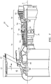
- FIG. 1 schematically illustrates a gas turbine engine 20 disclosed as a two-spool turbo fan that generally incorporates a fan section 22, a compressor section 24, a combustor section 26 and a turbine section 28.
- the fan section 22 drives air along a bypass flowpath while the compressor section 24 drives air along a core flowpath for compression and communication into the combustor section 26 then expansion through the turbine section 28.
- a turbofan in the disclosed non-limiting embodiment, it should be understood that the concepts described herein are not limited to use with turbofans as the teachings may be applied to other types of turbine engine architecture such as turbojets, turboshafts, three-spool turbofans, land-based turbine engines, and others.
- the engine 20 generally includes a low spool 30 and a high spool 32 mounted for rotation about an engine axis A via several bearing structures 38 and relative to a static engine case 36.
- the low spool 30 generally includes an inner shaft 40 that interconnects a fan 42 of the fan section 22, a low pressure compressor 44 ("LPC") of the compressor section 24 and a low pressure turbine 46 ("LPT") of the turbine section 28.
- the inner shaft 40 drives the fan 42 directly, or, through a geared architecture 48 to drive the fan 42 at a lower speed than the low spool 30.
- An exemplary reduction transmission may be an epicyclic transmission, namely a planetary or star gear system.
- the high spool 32 includes an outer shaft 50 that interconnects a high pressure compressor 52 ("HPC") of the compressor section 24 and a high pressure turbine 54 ("HPT") of the turbine section 28.
- a combustor 56 of the combustor section 26 is arranged between the HPC 52 and the HPT 54.
- the inner shaft 40 and the outer shaft 50 are concentric and rotate about the engine axis A. Core airflow is compressed by the LPC 44 then the HPC 52, mixed with the fuel and burned in the combustor 56, then expanded over the HPT 54 and the LPT 46.
- the LPT 46 and HPT 54 rotationally drive the respective low spool 30 and high spool 32 in response to the expansion.
- the gas turbine engine 20 is a high-bypass geared aircraft engine.
- the gas turbine engine 20 bypass ratio is greater than about six (6:1).
- the geared architecture 48 can include an epicyclic gear train, such as a planetary gear system or other gear system.
- the example epicyclic gear train has a gear reduction ratio of greater than about 2.3:1, and in another example is greater than about 2.5:1.
- the geared turbofan enables operation of the low spool 30 at higher speeds that can increase the operational efficiency of the LPC 44 and LPT 46 and render increased pressure in a fewer number of stages.
- a pressure ratio associated with the LPT 46 is pressure measured prior to the inlet of the LPT 46 as related to the pressure at the outlet of the LPT 46 prior to an exhaust nozzle of the gas turbine engine 20.
- the bypass ratio of the gas turbine engine 20 is greater than about ten (10:1); the fan diameter is significantly larger than the LPC 44; and the LPT 46 has a pressure ratio that is greater than about five (5:1). It should be understood; however, that the above parameters are only exemplary of one example of a geared architecture engine and that the present disclosure is applicable to other gas turbine engines including direct drive turbofans.
- a significant amount of thrust is provided by the bypass flow path B due to the high bypass ratio.
- the fan section 22 of the gas turbine engine 20 is designed for a particular flight condition - typically cruise at about 0.8 Mach and about 35,000 feet. This flight condition, with the gas turbine engine 20 at its best fuel consumption, is also known as Thrust Specific Fuel consumption (TSFC).
- TSFC Thrust Specific Fuel consumption
- Fan Pressure Ratio is the pressure ratio across a blade of the fan section 22 without the use of a fan exit guide vane system.
- the low Fan Pressure Ratio according to one, non-limiting, example of the gas turbine engine 20 is less than 1.45:1.
- Low Corrected Fan Tip Speed is the actual fan tip speed divided by an industry standard temperature correction of (T/518.7 0.5 ), where "T" represents the ambient temperature in degrees Rankine.
- the Low Corrected Fan Tip Speed according to one non-limiting example of the gas turbine engine 20 is less than about 1150 fps (351 m/s).
- the combustor section 26 generally includes an annular combustor 56 with an outer wall assembly 58, an inner wall assembly 60, and a diffuser case module 62 that surrounds wall assemblies 58, 60.
- the outer and inner wall assemblies 58, 60 are generally cylindrical and radially spaced apart such that an annular combustion chamber 64 is defined therebetween.
- the outer wall assembly 58 is spaced radially inward from an outer diffuser case 66 of the diffuser case module 62 to define an annular outer plenum 68.
- the inner wall assembly 60 is spaced radially outward from an inner diffuser case 70 of the diffuser case module 62 to define, in-part, an annular inner plenum 72.
- the combustion chamber 64 contains the combustion products that flow axially toward the turbine section 28.
- Each combustor wall assembly 58, 60 may be divided into a ring-shaped forward portion 58A, 60A and a ring-shaped aft or downstream portion 58B, 60B.
- At least one igniter (not shown) may project through the forward portion 58A of the outer wall assembly 58 for igniting a fuel and air mixture in the combustion chamber 64.
- a plurality of circumferentially spaced dilution holes 74 may communicate through the downstream portions 58B, 60B of the respective outer and inner wall assemblies 58, 60 for flowing dilution air from the respective plenums 68, 72 and into the combustion chamber 64 for generally improving combustion efficiency and cooling the combustion air that exits the combustor 56.
- the combustor 56 further includes a forward assembly 76 that receives compressed airflow from the compressor section 24 located immediately upstream.
- the forward assembly 76 generally includes an annular hood 78, a bulkhead assembly 80, and a plurality of swirlers 82 (one shown).
- Each of the swirlers 82 are circumferentially aligned with one of a plurality of fuel nozzles 84 (one shown) and a respective hood port 86 to project through the bulkhead assembly 80.
- the bulkhead assembly 80 includes a bulkhead support shell 88 secured to the forward portions 58A, 60A of the respective wall assemblies 58, 60 and a plurality of circumferentially distributed bulkhead heat sheilds or panels 90 secured to the bulkhead support shell 88 around each respective swirler 82 opening.
- the bulkhead support shell 88 is generally annular and the plurality of circumferentially distributed bulkhead panels 90 are segmented, typically one to each fuel nozzle 84 and swirler 82.
- the annular hood 78 extends radially between, and is secured to, the forward-most ends of the forward portion 58A, 60A of the respective wall assemblies 58, 60.
- Each one of the plurality of circumferentially distributed hood ports 86 receives a respective on the plurality of fuel nozzles 84, and facilitates the direction of compressed air into the forward end of the combustion chamber 64 through a swirler opening 92.
- Each fuel nozzle 84 may be secured to the outer diffuser case 66 of the case module 62 and projects through one of the hood ports 86 into the respective swirler 82.
- the forward assembly 76 introduces core combustion air into the forward section of the combustion chamber 64 while the remainder of compressor air enters the outer annular plenum 68 and the inner annular plenum 72.
- the plurality of fuel nozzles 84 and adjacent structure generate a blended fuel-air mixture that supports stable combustion in the combustion chamber 64.
- each wall assembly 58, 60 includes a support shell 94 that supports one or more thermally resistant heat shields or liners 96 that define the annular combustion chamber 64.
- the liners 96 are formed of a plurality of arcuate, floating, panels 98 that are generally rectilinear in cross section, manufactured of, for example, a nickel based super alloy that may be coated with a ceramic or other temperature resistant material (i.e. thermal barrier coating), and arranged to form a panel array mounted to the support shell 94.
- Each panel 98 of the liner 96 may be supported to the support shell 94 by at least one stanchion or threaded bolt 100 projecting rigidly from the panel 98 and through the shell 94 in such a way that limited thermal expansion and/or displacement between the shell and panel may occur.
- the support shell 94 has an inner surface 102 and an opposite outer surface 104 which faces and defines in-part a radial boundary of the outer plenum 68.
- the panel 98 has a cold surface 106 and an opposite hot surface 108 facing and defining in-part a radial boundary of the combustion chamber 64.
- the inner surface 102 and the cold surface 106 define a cooling cavity 110 therebetween, and radially between the outer cooling plenum 68 and the combustion chamber 64.
- a plurality of impingement holes 112 in the shell 94 extend through the inner and outer surfaces 102, 104 and are in fluid communication with the cooling plenum 68 and the cooling cavity 110 for flowing cooling air into the cavity 110.
- a plurality of film cooling holes 114 in the panel 98 extend through the cold and hot surfaces 106, 108 and are in fluid communication with the cooling cavity 110 and the combustion chamber 64 for flowing cooling air from the cavity 110 into the combustion chamber 64 that may, in-turn, form a film of cooling air over the hot surface 108 of the panel 98 for thermal protection.
- the panel 98 of the liner 96 has opposite first and second edges 116, 118 that extend circumferentially with respect to the engine axis A, and opposite third and fourth edges 120, 122 that extend axially between and connect to the circumferential edges 116, 118.
- a sealing interface structure 121 of the wall assembly 58A may extend generally about the perimeter of the panel 98 and proximate to the edges 116, 118, 120, 122 for minimizing unwanted cooling air leakage out of the cooling cavity 110 (further discussed below). As shown, for example, in FIG.
- the sealing interface structure 121 may include a rail 123 projecting (e.g., laterally outward) from the cold surface 106 of the panel 98 to a face 124 carried by the rail and opposing the inner surface 102 of the shell 94.
- the face 124 of the rail 123 may be in sealing contact with the surface 102 of the shell 94.
- a gap (see arrow 126) may exist between the face 124 and the surface 102 of the shell 94.
- gaps 126 may range from zero to about 0.010 inches or 10 mils (0.25 mm). More specifically, about an upper limit of 0.002 inches or 2 mils (0.05 mm) may be contributable toward thermal displacement during normal operation, and about an upper limit of 0.008 inches or 8 mils (0.2 mm) may be contributable from manufacturing tolerances.
- the face 124 is in sealing association with the inner surface 102 of the shell 94 with or without the gap 126. Any sealing leakage (see arrow 128) that may occur during operation on account of manufacturing tolerances, wear, thermal displacement, etc., is reduced (and may be minimized) by the particular sealing engagement of the sealing interface structure of the present disclosure (with or without a gap).
- the shell 94 may be somewhat bell-shaped with the cooling cavity 110 tapering down from a central location typically at the stanchions 100 and toward the circumferential edges 116, 118 of the panel 98. Such shape requires less cooling air provided leakage can be controlled and/or minimized.
- the present disclosure minimizes such leakage 128 by, for example, forming the face 124 with a lateral distance or width 130 at least about twice that of the thickness of the panel 98 (generally measured between the cold and hot surfaces 106, 108).
- the sealing interface structure 121 may not be continuous but may instead be elongated and longitudinally extending along one of more edges of the panel 98, as one example.
- the sealing interface structure 121 may be one of two sealing interfaces where each interface extends only along respective circumferential edges 116, 118 of the panel 98.
- the heat shield 96 may not be divided into separate panels but may be one unitary ring. Orientation and configurations of the sealing interface structure 121 may therefore be different than that described without deviating from the novel aspects of the present disclosure.
- a sealing interface structure 121' of the second embodiment has a continuous inner sealing segment 132 and a continuous outer sealing segment 134 both extending longitudinally and generally separated from one-another by a chamber 136 where air may recirculate.
- Each segment 132, 134 of the sealing interface structure 121' carries a respective inner and outer segment 138, 140 of a face 124'.
- the inner and outer segments 138, 140 oppose an inner surface 102' of the shell 94' and thereby define a gap 126' therebetween.
- a mid segment 142 of the face 124' spans laterally between the inner and outer segments, is further spaced from the inner surface 102 and defines the chamber 136 with the opposing surface.
- leakage air 128' will be limited. For example, any such leakage air 128' will need to travel from a cooling cavity 110' into the gap 126' between the inner surface 102' and the inner segment 138 of the face 124'. From there, the leakage air would need to additionally enter the chamber 136 where the air may be guided to recirculate upon itself or otherwise create an airflow turbulence that produces a backpressure which minimizes air leakage. Such leakage air 128' would further need to re-enter the gap 126' between the outer segment 140 of the face 124' and the inner surface 102' of the shell 94' where the limited leakage air may then enter the combustion chamber 64'.
- cross section of the mid segment 142 is curved or cupped (e.g., concave), any number of cross sectional profiles of the mid segment 142 will work provided a chamber is defined where air may generally recirculate.
Landscapes
- Engineering & Computer Science (AREA)
- Chemical & Material Sciences (AREA)
- Combustion & Propulsion (AREA)
- Mechanical Engineering (AREA)
- General Engineering & Computer Science (AREA)
- Ceramic Engineering (AREA)
- Turbine Rotor Nozzle Sealing (AREA)
Claims (9)
- Ensemble paroi de chambre de combustion (58) pour une turbine à gaz comprenant :une coque (94) ; etune garniture (96) ayant une épaisseur (131) avec une cavité de refroidissement (110) définie entre la coque (94) et la garniture (96), dans lequel la garniture (96) est formée d'une pluralité de panneaux flottants incurvés (98) ; etune structure d'interface d'étanchéité (121) venant en prise de manière étanche avec et portée entre la coque (94) et la garniture (96) pour résister à la fuite d'air de refroidissement hors de la cavité de refroidissement (110), la structure d'interface d'étanchéité (121) ayant une largeur d'étanchéité (130) d'au moins deux fois l'épaisseur de la garniture (96) ;caractérisé en ce que :la coque (94) possède une surface intérieure (102) tournée vers la cavité de refroidissement (110) et convergeant vers la structure d'interface d'étanchéité (121) ;la structure d'interface d'étanchéité (121) inclut un rail allongé (123) fixé à la garniture (98) ; etle rail (123) inclut des segments d'étanchéité intérieur (138) et extérieur (140) et définit une ou la chambre (136) entre eux pour amener l'air à recirculer ou bien créer des turbulences de l'écoulement d'air ;dans lequel le rail (123) est situé à proximité d'un bord (118) d'un des panneaux (98) et fait saillie latéralement vers l'extérieur d'une surface froide (106) du panneau respectif (98).
- Ensemble paroi de chambre de combustion selon la revendication 1, dans lequel la cavité de refroidissement (110) se rétrécit vers la structure d'interface d'étanchéité (121).
- Ensemble paroi de chambre de combustion selon la revendication 1 ou 2, dans lequel la structure d'interface d'étanchéité (121) inclut une chambre (136) pour amener l'air à recirculer ou bien créer des turbulences de l'écoulement d'air.
- Ensemble paroi de chambre de combustion selon la revendication 3, dans lequel la structure d'interface d'étanchéité (121) inclut un segment d'étanchéité intérieur (132) et un segment d'étanchéité extérieur (134) avec la chambre (136) située entre les segments d'étanchéité intérieur (132) et extérieur (134).
- Ensemble paroi de chambre de combustion selon une quelconque revendication précédente, dans lequel la coque (94) est concentrique à un axe (A), la garniture (96) inclut et s'étend axialement entre des premier (116) et second (118) bords opposés s'étendant tous les deux circonférentiellement, et la structure d'interface d'étanchéité (121) est à proximité d'un des premier (116) et second (118) bords.
- Ensemble paroi de chambre de combustion selon une quelconque revendication précédente, dans lequel une pluralité de trous de refroidissement (114) sont espacés circonférentiellement les uns des autres, communiquent à travers la garniture (96) et sont à proximité du rail (123).
- Ensemble paroi de chambre de combustion selon une quelconque revendication précédente, dans lequel une pluralité de trous d'impact (112) communiquent à travers la coque (94) et avec la cavité de refroidissement (110).
- Ensemble paroi de chambre de combustion selon une quelconque revendication précédente, dans lequel la structure d'interface d'étanchéité (121) possède un intervalle (126 ; 126') défini entre la garniture (98) et la coque (94) qui tombe dans la plage d'environ zéro millième de pouce à dix millièmes de pouce (0 mm à 0,25 mm).
- Ensemble paroi selon la revendication 1, comprenant en outre :une pluralité de trous d'impact (112) dans la coque (94) qui sont en communication fluidique avec la cavité de refroidissement (110), une pluralité de trous de refroidissement (116) dans la garniture (98) qui sont en communication fluidique avec la cavité de refroidissement (110) et une chambre de combustion (64) définie au moins en partie par la garniture (98) ;dans lequel la structure d'étanchéité (121) possède une face incluant un segment intérieur (138), un segment intermédiaire (142) et un segment extérieur (140), etdans lequel le segment intermédiaire (142) et la coque (94) définissent une chambre (136), le segment intérieur (138) est en association d'étanchéité avec la coque (94) généralement entre la cavité de refroidissement (110) et la chambre (136), et le segment extérieur (140) est en association d'étanchéité avec la coque (94) globalement entre la chambre (136) et la chambre de combustion (64).
Applications Claiming Priority (1)
| Application Number | Priority Date | Filing Date | Title |
|---|---|---|---|
| US201461977311P | 2014-04-09 | 2014-04-09 |
Publications (2)
| Publication Number | Publication Date |
|---|---|
| EP2930428A1 EP2930428A1 (fr) | 2015-10-14 |
| EP2930428B1 true EP2930428B1 (fr) | 2019-11-13 |
Family
ID=52823513
Family Applications (1)
| Application Number | Title | Priority Date | Filing Date |
|---|---|---|---|
| EP15162912.8A Active EP2930428B1 (fr) | 2014-04-09 | 2015-04-09 | Ensemble paroi de chambre de combustion pour un moteur de turbine |
Country Status (2)
| Country | Link |
|---|---|
| US (1) | US9909761B2 (fr) |
| EP (1) | EP2930428B1 (fr) |
Families Citing this family (12)
| Publication number | Priority date | Publication date | Assignee | Title |
|---|---|---|---|---|
| US10197285B2 (en) * | 2013-12-06 | 2019-02-05 | United Technologies Corporation | Gas turbine engine wall assembly interface |
| EP3099976B1 (fr) * | 2014-01-30 | 2019-03-13 | United Technologies Corporation | Flux de refroidissement pour un panneau principal dans une chambre de combustion de moteur à turbine à gaz |
| WO2015117137A1 (fr) * | 2014-02-03 | 2015-08-06 | United Technologies Corporation | Refroidissement par film d'air d'une paroi de chambre de combustion d'un moteur à turbine |
| US10041675B2 (en) * | 2014-06-04 | 2018-08-07 | Pratt & Whitney Canada Corp. | Multiple ventilated rails for sealing of combustor heat shields |
| US10746403B2 (en) | 2014-12-12 | 2020-08-18 | Raytheon Technologies Corporation | Cooled wall assembly for a combustor and method of design |
| GB201603166D0 (en) * | 2016-02-24 | 2016-04-06 | Rolls Royce Plc | A combustion chamber |
| US20180335212A1 (en) * | 2017-05-18 | 2018-11-22 | United Technologies Corporation | Redundant endrail for combustor panel |
| US10830435B2 (en) * | 2018-02-06 | 2020-11-10 | Raytheon Technologies Corporation | Diffusing hole for rail effusion |
| US11009230B2 (en) | 2018-02-06 | 2021-05-18 | Raytheon Technologies Corporation | Undercut combustor panel rail |
| US11248791B2 (en) | 2018-02-06 | 2022-02-15 | Raytheon Technologies Corporation | Pull-plane effusion combustor panel |
| US11022307B2 (en) | 2018-02-22 | 2021-06-01 | Raytheon Technology Corporation | Gas turbine combustor heat shield panel having multi-direction hole for rail effusion cooling |
| US20210372616A1 (en) * | 2020-05-27 | 2021-12-02 | Raytheon Technologies Corporation | Multi-walled structure for a gas turbine engine |
Family Cites Families (11)
| Publication number | Priority date | Publication date | Assignee | Title |
|---|---|---|---|---|
| US4162077A (en) | 1977-12-28 | 1979-07-24 | United Technologies Corporation | Wide channel seal |
| US4682933A (en) | 1984-10-17 | 1987-07-28 | Rockwell International Corporation | Labyrinthine turbine-rotor-blade tip seal |
| GB2298267B (en) * | 1995-02-23 | 1999-01-13 | Rolls Royce Plc | An arrangement of heat resistant tiles for a gas turbine engine combustor |
| US5758503A (en) | 1995-05-03 | 1998-06-02 | United Technologies Corporation | Gas turbine combustor |
| EP1284390A1 (fr) | 2001-06-27 | 2003-02-19 | Siemens Aktiengesellschaft | Ensemble bouclier thermique pour un composant acheminant un gaz chaud, notamment pour des pièces de structure de turbines à gaz |
| US20050034399A1 (en) * | 2002-01-15 | 2005-02-17 | Rolls-Royce Plc | Double wall combustor tile arrangement |
| US7140185B2 (en) * | 2004-07-12 | 2006-11-28 | United Technologies Corporation | Heatshielded article |
| GB2453946B (en) * | 2007-10-23 | 2010-07-14 | Rolls Royce Plc | A Wall Element for use in Combustion Apparatus |
| US9587832B2 (en) * | 2008-10-01 | 2017-03-07 | United Technologies Corporation | Structures with adaptive cooling |
| US9534783B2 (en) * | 2011-07-21 | 2017-01-03 | United Technologies Corporation | Insert adjacent to a heat shield element for a gas turbine engine combustor |
| WO2014133615A1 (fr) * | 2013-03-01 | 2014-09-04 | Rolls-Royce Corporation | Joint à bande bimétallique |
-
2015
- 2015-04-07 US US14/680,649 patent/US9909761B2/en active Active
- 2015-04-09 EP EP15162912.8A patent/EP2930428B1/fr active Active
Non-Patent Citations (1)
| Title |
|---|
| None * |
Also Published As
| Publication number | Publication date |
|---|---|
| US9909761B2 (en) | 2018-03-06 |
| US20150292741A1 (en) | 2015-10-15 |
| EP2930428A1 (fr) | 2015-10-14 |
Similar Documents
| Publication | Publication Date | Title |
|---|---|---|
| EP2930428B1 (fr) | Ensemble paroi de chambre de combustion pour un moteur de turbine | |
| US11073284B2 (en) | Cooled grommet for a combustor wall assembly | |
| US9964307B2 (en) | Interface heat shield for a combustor of a gas turbine engine | |
| EP3018416B1 (fr) | Paroi flottante refroidie par film et par impact avec agencements sur sa face arrière | |
| EP3048371B1 (fr) | Contrôle de transfert thermique passif à trou de dilution de dispositif de combustion | |
| EP2927595B1 (fr) | Ensemble d'oeillet et procédé de conception | |
| EP3026343B1 (fr) | Structure d'orifice auto-refroidi | |
| EP2963346B1 (fr) | Structure d'orifice auto-refroidie | |
| EP3087266B1 (fr) | Configuration de trous de dilution à écoulements multiples pour un moteur à turbine à gaz et procédé de fonctionnement | |
| EP2977680B1 (fr) | Ensemble de trou de dilution | |
| US9810430B2 (en) | Conjoined grommet assembly for a combustor | |
| EP2904253B1 (fr) | Foyer doté d'une rondelle présentant une lèvre en saillie | |
| US10112557B2 (en) | Thermally compliant grommet assembly | |
| EP3040524B1 (fr) | Carter de diffuseur externe pour une turbine à gaz | |
| US11326518B2 (en) | Cooled component for a gas turbine engine |
Legal Events
| Date | Code | Title | Description |
|---|---|---|---|
| PUAI | Public reference made under article 153(3) epc to a published international application that has entered the european phase |
Free format text: ORIGINAL CODE: 0009012 |
|
| AK | Designated contracting states |
Kind code of ref document: A1 Designated state(s): AL AT BE BG CH CY CZ DE DK EE ES FI FR GB GR HR HU IE IS IT LI LT LU LV MC MK MT NL NO PL PT RO RS SE SI SK SM TR |
|
| AX | Request for extension of the european patent |
Extension state: BA ME |
|
| 17P | Request for examination filed |
Effective date: 20160414 |
|
| RBV | Designated contracting states (corrected) |
Designated state(s): AL AT BE BG CH CY CZ DE DK EE ES FI FR GB GR HR HU IE IS IT LI LT LU LV MC MK MT NL NO PL PT RO RS SE SI SK SM TR |
|
| RAP1 | Party data changed (applicant data changed or rights of an application transferred) |
Owner name: UNITED TECHNOLOGIES CORPORATION |
|
| STAA | Information on the status of an ep patent application or granted ep patent |
Free format text: STATUS: EXAMINATION IS IN PROGRESS |
|
| 17Q | First examination report despatched |
Effective date: 20180709 |
|
| GRAP | Despatch of communication of intention to grant a patent |
Free format text: ORIGINAL CODE: EPIDOSNIGR1 |
|
| STAA | Information on the status of an ep patent application or granted ep patent |
Free format text: STATUS: GRANT OF PATENT IS INTENDED |
|
| INTG | Intention to grant announced |
Effective date: 20190606 |
|
| GRAS | Grant fee paid |
Free format text: ORIGINAL CODE: EPIDOSNIGR3 |
|
| GRAA | (expected) grant |
Free format text: ORIGINAL CODE: 0009210 |
|
| STAA | Information on the status of an ep patent application or granted ep patent |
Free format text: STATUS: THE PATENT HAS BEEN GRANTED |
|
| AK | Designated contracting states |
Kind code of ref document: B1 Designated state(s): AL AT BE BG CH CY CZ DE DK EE ES FI FR GB GR HR HU IE IS IT LI LT LU LV MC MK MT NL NO PL PT RO RS SE SI SK SM TR |
|
| REG | Reference to a national code |
Ref country code: CH Ref legal event code: EP Ref country code: AT Ref legal event code: REF Ref document number: 1202045 Country of ref document: AT Kind code of ref document: T Effective date: 20191115 |
|
| REG | Reference to a national code |
Ref country code: DE Ref legal event code: R096 Ref document number: 602015041497 Country of ref document: DE |
|
| REG | Reference to a national code |
Ref country code: IE Ref legal event code: FG4D |
|
| REG | Reference to a national code |
Ref country code: NL Ref legal event code: MP Effective date: 20191113 |
|
| REG | Reference to a national code |
Ref country code: LT Ref legal event code: MG4D |
|
| PG25 | Lapsed in a contracting state [announced via postgrant information from national office to epo] |
Ref country code: PL Free format text: LAPSE BECAUSE OF FAILURE TO SUBMIT A TRANSLATION OF THE DESCRIPTION OR TO PAY THE FEE WITHIN THE PRESCRIBED TIME-LIMIT Effective date: 20191113 Ref country code: SE Free format text: LAPSE BECAUSE OF FAILURE TO SUBMIT A TRANSLATION OF THE DESCRIPTION OR TO PAY THE FEE WITHIN THE PRESCRIBED TIME-LIMIT Effective date: 20191113 Ref country code: GR Free format text: LAPSE BECAUSE OF FAILURE TO SUBMIT A TRANSLATION OF THE DESCRIPTION OR TO PAY THE FEE WITHIN THE PRESCRIBED TIME-LIMIT Effective date: 20200214 Ref country code: LV Free format text: LAPSE BECAUSE OF FAILURE TO SUBMIT A TRANSLATION OF THE DESCRIPTION OR TO PAY THE FEE WITHIN THE PRESCRIBED TIME-LIMIT Effective date: 20191113 Ref country code: NO Free format text: LAPSE BECAUSE OF FAILURE TO SUBMIT A TRANSLATION OF THE DESCRIPTION OR TO PAY THE FEE WITHIN THE PRESCRIBED TIME-LIMIT Effective date: 20200213 Ref country code: PT Free format text: LAPSE BECAUSE OF FAILURE TO SUBMIT A TRANSLATION OF THE DESCRIPTION OR TO PAY THE FEE WITHIN THE PRESCRIBED TIME-LIMIT Effective date: 20200313 Ref country code: FI Free format text: LAPSE BECAUSE OF FAILURE TO SUBMIT A TRANSLATION OF THE DESCRIPTION OR TO PAY THE FEE WITHIN THE PRESCRIBED TIME-LIMIT Effective date: 20191113 Ref country code: BG Free format text: LAPSE BECAUSE OF FAILURE TO SUBMIT A TRANSLATION OF THE DESCRIPTION OR TO PAY THE FEE WITHIN THE PRESCRIBED TIME-LIMIT Effective date: 20200213 Ref country code: LT Free format text: LAPSE BECAUSE OF FAILURE TO SUBMIT A TRANSLATION OF THE DESCRIPTION OR TO PAY THE FEE WITHIN THE PRESCRIBED TIME-LIMIT Effective date: 20191113 Ref country code: NL Free format text: LAPSE BECAUSE OF FAILURE TO SUBMIT A TRANSLATION OF THE DESCRIPTION OR TO PAY THE FEE WITHIN THE PRESCRIBED TIME-LIMIT Effective date: 20191113 |
|
| PG25 | Lapsed in a contracting state [announced via postgrant information from national office to epo] |
Ref country code: RS Free format text: LAPSE BECAUSE OF FAILURE TO SUBMIT A TRANSLATION OF THE DESCRIPTION OR TO PAY THE FEE WITHIN THE PRESCRIBED TIME-LIMIT Effective date: 20191113 Ref country code: HR Free format text: LAPSE BECAUSE OF FAILURE TO SUBMIT A TRANSLATION OF THE DESCRIPTION OR TO PAY THE FEE WITHIN THE PRESCRIBED TIME-LIMIT Effective date: 20191113 Ref country code: IS Free format text: LAPSE BECAUSE OF FAILURE TO SUBMIT A TRANSLATION OF THE DESCRIPTION OR TO PAY THE FEE WITHIN THE PRESCRIBED TIME-LIMIT Effective date: 20200313 |
|
| PG25 | Lapsed in a contracting state [announced via postgrant information from national office to epo] |
Ref country code: AL Free format text: LAPSE BECAUSE OF FAILURE TO SUBMIT A TRANSLATION OF THE DESCRIPTION OR TO PAY THE FEE WITHIN THE PRESCRIBED TIME-LIMIT Effective date: 20191113 |
|
| PG25 | Lapsed in a contracting state [announced via postgrant information from national office to epo] |
Ref country code: CZ Free format text: LAPSE BECAUSE OF FAILURE TO SUBMIT A TRANSLATION OF THE DESCRIPTION OR TO PAY THE FEE WITHIN THE PRESCRIBED TIME-LIMIT Effective date: 20191113 Ref country code: RO Free format text: LAPSE BECAUSE OF FAILURE TO SUBMIT A TRANSLATION OF THE DESCRIPTION OR TO PAY THE FEE WITHIN THE PRESCRIBED TIME-LIMIT Effective date: 20191113 Ref country code: EE Free format text: LAPSE BECAUSE OF FAILURE TO SUBMIT A TRANSLATION OF THE DESCRIPTION OR TO PAY THE FEE WITHIN THE PRESCRIBED TIME-LIMIT Effective date: 20191113 Ref country code: DK Free format text: LAPSE BECAUSE OF FAILURE TO SUBMIT A TRANSLATION OF THE DESCRIPTION OR TO PAY THE FEE WITHIN THE PRESCRIBED TIME-LIMIT Effective date: 20191113 Ref country code: ES Free format text: LAPSE BECAUSE OF FAILURE TO SUBMIT A TRANSLATION OF THE DESCRIPTION OR TO PAY THE FEE WITHIN THE PRESCRIBED TIME-LIMIT Effective date: 20191113 |
|
| REG | Reference to a national code |
Ref country code: DE Ref legal event code: R097 Ref document number: 602015041497 Country of ref document: DE |
|
| REG | Reference to a national code |
Ref country code: AT Ref legal event code: MK05 Ref document number: 1202045 Country of ref document: AT Kind code of ref document: T Effective date: 20191113 |
|
| PG25 | Lapsed in a contracting state [announced via postgrant information from national office to epo] |
Ref country code: SK Free format text: LAPSE BECAUSE OF FAILURE TO SUBMIT A TRANSLATION OF THE DESCRIPTION OR TO PAY THE FEE WITHIN THE PRESCRIBED TIME-LIMIT Effective date: 20191113 Ref country code: SM Free format text: LAPSE BECAUSE OF FAILURE TO SUBMIT A TRANSLATION OF THE DESCRIPTION OR TO PAY THE FEE WITHIN THE PRESCRIBED TIME-LIMIT Effective date: 20191113 |
|
| PLBE | No opposition filed within time limit |
Free format text: ORIGINAL CODE: 0009261 |
|
| STAA | Information on the status of an ep patent application or granted ep patent |
Free format text: STATUS: NO OPPOSITION FILED WITHIN TIME LIMIT |
|
| 26N | No opposition filed |
Effective date: 20200814 |
|
| PG25 | Lapsed in a contracting state [announced via postgrant information from national office to epo] |
Ref country code: SI Free format text: LAPSE BECAUSE OF FAILURE TO SUBMIT A TRANSLATION OF THE DESCRIPTION OR TO PAY THE FEE WITHIN THE PRESCRIBED TIME-LIMIT Effective date: 20191113 Ref country code: MC Free format text: LAPSE BECAUSE OF FAILURE TO SUBMIT A TRANSLATION OF THE DESCRIPTION OR TO PAY THE FEE WITHIN THE PRESCRIBED TIME-LIMIT Effective date: 20191113 Ref country code: AT Free format text: LAPSE BECAUSE OF FAILURE TO SUBMIT A TRANSLATION OF THE DESCRIPTION OR TO PAY THE FEE WITHIN THE PRESCRIBED TIME-LIMIT Effective date: 20191113 |
|
| REG | Reference to a national code |
Ref country code: CH Ref legal event code: PL |
|
| PG25 | Lapsed in a contracting state [announced via postgrant information from national office to epo] |
Ref country code: LI Free format text: LAPSE BECAUSE OF NON-PAYMENT OF DUE FEES Effective date: 20200430 Ref country code: IT Free format text: LAPSE BECAUSE OF FAILURE TO SUBMIT A TRANSLATION OF THE DESCRIPTION OR TO PAY THE FEE WITHIN THE PRESCRIBED TIME-LIMIT Effective date: 20191113 Ref country code: CH Free format text: LAPSE BECAUSE OF NON-PAYMENT OF DUE FEES Effective date: 20200430 Ref country code: LU Free format text: LAPSE BECAUSE OF NON-PAYMENT OF DUE FEES Effective date: 20200409 |
|
| REG | Reference to a national code |
Ref country code: BE Ref legal event code: MM Effective date: 20200430 |
|
| PG25 | Lapsed in a contracting state [announced via postgrant information from national office to epo] |
Ref country code: BE Free format text: LAPSE BECAUSE OF NON-PAYMENT OF DUE FEES Effective date: 20200430 |
|
| PG25 | Lapsed in a contracting state [announced via postgrant information from national office to epo] |
Ref country code: IE Free format text: LAPSE BECAUSE OF NON-PAYMENT OF DUE FEES Effective date: 20200409 |
|
| PG25 | Lapsed in a contracting state [announced via postgrant information from national office to epo] |
Ref country code: TR Free format text: LAPSE BECAUSE OF FAILURE TO SUBMIT A TRANSLATION OF THE DESCRIPTION OR TO PAY THE FEE WITHIN THE PRESCRIBED TIME-LIMIT Effective date: 20191113 Ref country code: MT Free format text: LAPSE BECAUSE OF FAILURE TO SUBMIT A TRANSLATION OF THE DESCRIPTION OR TO PAY THE FEE WITHIN THE PRESCRIBED TIME-LIMIT Effective date: 20191113 Ref country code: CY Free format text: LAPSE BECAUSE OF FAILURE TO SUBMIT A TRANSLATION OF THE DESCRIPTION OR TO PAY THE FEE WITHIN THE PRESCRIBED TIME-LIMIT Effective date: 20191113 |
|
| PG25 | Lapsed in a contracting state [announced via postgrant information from national office to epo] |
Ref country code: MK Free format text: LAPSE BECAUSE OF FAILURE TO SUBMIT A TRANSLATION OF THE DESCRIPTION OR TO PAY THE FEE WITHIN THE PRESCRIBED TIME-LIMIT Effective date: 20191113 |
|
| REG | Reference to a national code |
Ref country code: DE Ref legal event code: R081 Ref document number: 602015041497 Country of ref document: DE Owner name: RAYTHEON TECHNOLOGIES CORPORATION (N.D.GES.D.S, US Free format text: FORMER OWNER: UNITED TECHNOLOGIES CORPORATION, FARMINGTON, CONN., US |
|
| P01 | Opt-out of the competence of the unified patent court (upc) registered |
Effective date: 20230520 |
|
| PGFP | Annual fee paid to national office [announced via postgrant information from national office to epo] |
Ref country code: DE Payment date: 20230321 Year of fee payment: 9 |
|
| PGFP | Annual fee paid to national office [announced via postgrant information from national office to epo] |
Ref country code: GB Payment date: 20240320 Year of fee payment: 10 |
|
| PGFP | Annual fee paid to national office [announced via postgrant information from national office to epo] |
Ref country code: FR Payment date: 20240320 Year of fee payment: 10 |