EP2930304A1 - High pressure compressor thermal shield apparatus and system - Google Patents
High pressure compressor thermal shield apparatus and system Download PDFInfo
- Publication number
- EP2930304A1 EP2930304A1 EP15163327.8A EP15163327A EP2930304A1 EP 2930304 A1 EP2930304 A1 EP 2930304A1 EP 15163327 A EP15163327 A EP 15163327A EP 2930304 A1 EP2930304 A1 EP 2930304A1
- Authority
- EP
- European Patent Office
- Prior art keywords
- rotor
- thermal shield
- high pressure
- pressure compressor
- rotor hub
- Prior art date
- Legal status (The legal status is an assumption and is not a legal conclusion. Google has not performed a legal analysis and makes no representation as to the accuracy of the status listed.)
- Granted
Links
Images




Classifications
-
- F—MECHANICAL ENGINEERING; LIGHTING; HEATING; WEAPONS; BLASTING
- F01—MACHINES OR ENGINES IN GENERAL; ENGINE PLANTS IN GENERAL; STEAM ENGINES
- F01D—NON-POSITIVE DISPLACEMENT MACHINES OR ENGINES, e.g. STEAM TURBINES
- F01D25/00—Component parts, details, or accessories, not provided for in, or of interest apart from, other groups
- F01D25/08—Cooling; Heating; Heat-insulation
- F01D25/12—Cooling
-
- F—MECHANICAL ENGINEERING; LIGHTING; HEATING; WEAPONS; BLASTING
- F01—MACHINES OR ENGINES IN GENERAL; ENGINE PLANTS IN GENERAL; STEAM ENGINES
- F01D—NON-POSITIVE DISPLACEMENT MACHINES OR ENGINES, e.g. STEAM TURBINES
- F01D5/00—Blades; Blade-carrying members; Heating, heat-insulating, cooling or antivibration means on the blades or the members
- F01D5/02—Blade-carrying members, e.g. rotors
- F01D5/08—Heating, heat-insulating or cooling means
- F01D5/081—Cooling fluid being directed on the side of the rotor disc or at the roots of the blades
- F01D5/084—Cooling fluid being directed on the side of the rotor disc or at the roots of the blades the fluid circulating at the periphery of a multistage rotor, e.g. of drum type
-
- F—MECHANICAL ENGINEERING; LIGHTING; HEATING; WEAPONS; BLASTING
- F01—MACHINES OR ENGINES IN GENERAL; ENGINE PLANTS IN GENERAL; STEAM ENGINES
- F01D—NON-POSITIVE DISPLACEMENT MACHINES OR ENGINES, e.g. STEAM TURBINES
- F01D1/00—Non-positive-displacement machines or engines, e.g. steam turbines
- F01D1/02—Non-positive-displacement machines or engines, e.g. steam turbines with stationary working-fluid guiding means and bladed or like rotor, e.g. multi-bladed impulse steam turbines
-
- F—MECHANICAL ENGINEERING; LIGHTING; HEATING; WEAPONS; BLASTING
- F01—MACHINES OR ENGINES IN GENERAL; ENGINE PLANTS IN GENERAL; STEAM ENGINES
- F01D—NON-POSITIVE DISPLACEMENT MACHINES OR ENGINES, e.g. STEAM TURBINES
- F01D11/00—Preventing or minimising internal leakage of working-fluid, e.g. between stages
- F01D11/001—Preventing or minimising internal leakage of working-fluid, e.g. between stages for sealing space between stator blade and rotor
-
- F—MECHANICAL ENGINEERING; LIGHTING; HEATING; WEAPONS; BLASTING
- F01—MACHINES OR ENGINES IN GENERAL; ENGINE PLANTS IN GENERAL; STEAM ENGINES
- F01D—NON-POSITIVE DISPLACEMENT MACHINES OR ENGINES, e.g. STEAM TURBINES
- F01D11/00—Preventing or minimising internal leakage of working-fluid, e.g. between stages
- F01D11/02—Preventing or minimising internal leakage of working-fluid, e.g. between stages by non-contact sealings, e.g. of labyrinth type
-
- F—MECHANICAL ENGINEERING; LIGHTING; HEATING; WEAPONS; BLASTING
- F01—MACHINES OR ENGINES IN GENERAL; ENGINE PLANTS IN GENERAL; STEAM ENGINES
- F01D—NON-POSITIVE DISPLACEMENT MACHINES OR ENGINES, e.g. STEAM TURBINES
- F01D25/00—Component parts, details, or accessories, not provided for in, or of interest apart from, other groups
- F01D25/08—Cooling; Heating; Heat-insulation
- F01D25/14—Casings modified therefor
- F01D25/145—Thermally insulated casings
-
- F—MECHANICAL ENGINEERING; LIGHTING; HEATING; WEAPONS; BLASTING
- F01—MACHINES OR ENGINES IN GENERAL; ENGINE PLANTS IN GENERAL; STEAM ENGINES
- F01D—NON-POSITIVE DISPLACEMENT MACHINES OR ENGINES, e.g. STEAM TURBINES
- F01D5/00—Blades; Blade-carrying members; Heating, heat-insulating, cooling or antivibration means on the blades or the members
- F01D5/02—Blade-carrying members, e.g. rotors
- F01D5/06—Rotors for more than one axial stage, e.g. of drum or multiple disc type; Details thereof, e.g. shafts, shaft connections
-
- F—MECHANICAL ENGINEERING; LIGHTING; HEATING; WEAPONS; BLASTING
- F02—COMBUSTION ENGINES; HOT-GAS OR COMBUSTION-PRODUCT ENGINE PLANTS
- F02C—GAS-TURBINE PLANTS; AIR INTAKES FOR JET-PROPULSION PLANTS; CONTROLLING FUEL SUPPLY IN AIR-BREATHING JET-PROPULSION PLANTS
- F02C7/00—Features, components parts, details or accessories, not provided for in, or of interest apart form groups F02C1/00 - F02C6/00; Air intakes for jet-propulsion plants
- F02C7/24—Heat or noise insulation
-
- F—MECHANICAL ENGINEERING; LIGHTING; HEATING; WEAPONS; BLASTING
- F05—INDEXING SCHEMES RELATING TO ENGINES OR PUMPS IN VARIOUS SUBCLASSES OF CLASSES F01-F04
- F05D—INDEXING SCHEME FOR ASPECTS RELATING TO NON-POSITIVE-DISPLACEMENT MACHINES OR ENGINES, GAS-TURBINES OR JET-PROPULSION PLANTS
- F05D2220/00—Application
- F05D2220/30—Application in turbines
- F05D2220/32—Application in turbines in gas turbines
-
- F—MECHANICAL ENGINEERING; LIGHTING; HEATING; WEAPONS; BLASTING
- F05—INDEXING SCHEMES RELATING TO ENGINES OR PUMPS IN VARIOUS SUBCLASSES OF CLASSES F01-F04
- F05D—INDEXING SCHEME FOR ASPECTS RELATING TO NON-POSITIVE-DISPLACEMENT MACHINES OR ENGINES, GAS-TURBINES OR JET-PROPULSION PLANTS
- F05D2220/00—Application
- F05D2220/30—Application in turbines
- F05D2220/32—Application in turbines in gas turbines
- F05D2220/321—Application in turbines in gas turbines for a special turbine stage
- F05D2220/3216—Application in turbines in gas turbines for a special turbine stage for a special compressor stage
- F05D2220/3219—Application in turbines in gas turbines for a special turbine stage for a special compressor stage for the last stage of a compressor or a high pressure compressor
-
- F—MECHANICAL ENGINEERING; LIGHTING; HEATING; WEAPONS; BLASTING
- F05—INDEXING SCHEMES RELATING TO ENGINES OR PUMPS IN VARIOUS SUBCLASSES OF CLASSES F01-F04
- F05D—INDEXING SCHEME FOR ASPECTS RELATING TO NON-POSITIVE-DISPLACEMENT MACHINES OR ENGINES, GAS-TURBINES OR JET-PROPULSION PLANTS
- F05D2240/00—Components
- F05D2240/10—Stators
- F05D2240/12—Fluid guiding means, e.g. vanes
-
- F—MECHANICAL ENGINEERING; LIGHTING; HEATING; WEAPONS; BLASTING
- F05—INDEXING SCHEMES RELATING TO ENGINES OR PUMPS IN VARIOUS SUBCLASSES OF CLASSES F01-F04
- F05D—INDEXING SCHEME FOR ASPECTS RELATING TO NON-POSITIVE-DISPLACEMENT MACHINES OR ENGINES, GAS-TURBINES OR JET-PROPULSION PLANTS
- F05D2240/00—Components
- F05D2240/10—Stators
- F05D2240/15—Heat shield
-
- F—MECHANICAL ENGINEERING; LIGHTING; HEATING; WEAPONS; BLASTING
- F05—INDEXING SCHEMES RELATING TO ENGINES OR PUMPS IN VARIOUS SUBCLASSES OF CLASSES F01-F04
- F05D—INDEXING SCHEME FOR ASPECTS RELATING TO NON-POSITIVE-DISPLACEMENT MACHINES OR ENGINES, GAS-TURBINES OR JET-PROPULSION PLANTS
- F05D2240/00—Components
- F05D2240/20—Rotors
- F05D2240/24—Rotors for turbines
-
- F—MECHANICAL ENGINEERING; LIGHTING; HEATING; WEAPONS; BLASTING
- F05—INDEXING SCHEMES RELATING TO ENGINES OR PUMPS IN VARIOUS SUBCLASSES OF CLASSES F01-F04
- F05D—INDEXING SCHEME FOR ASPECTS RELATING TO NON-POSITIVE-DISPLACEMENT MACHINES OR ENGINES, GAS-TURBINES OR JET-PROPULSION PLANTS
- F05D2260/00—Function
- F05D2260/20—Heat transfer, e.g. cooling
- F05D2260/231—Preventing heat transfer
-
- F—MECHANICAL ENGINEERING; LIGHTING; HEATING; WEAPONS; BLASTING
- F05—INDEXING SCHEMES RELATING TO ENGINES OR PUMPS IN VARIOUS SUBCLASSES OF CLASSES F01-F04
- F05D—INDEXING SCHEME FOR ASPECTS RELATING TO NON-POSITIVE-DISPLACEMENT MACHINES OR ENGINES, GAS-TURBINES OR JET-PROPULSION PLANTS
- F05D2260/00—Function
- F05D2260/30—Retaining components in desired mutual position
- F05D2260/31—Retaining bolts or nuts
-
- Y—GENERAL TAGGING OF NEW TECHNOLOGICAL DEVELOPMENTS; GENERAL TAGGING OF CROSS-SECTIONAL TECHNOLOGIES SPANNING OVER SEVERAL SECTIONS OF THE IPC; TECHNICAL SUBJECTS COVERED BY FORMER USPC CROSS-REFERENCE ART COLLECTIONS [XRACs] AND DIGESTS
- Y02—TECHNOLOGIES OR APPLICATIONS FOR MITIGATION OR ADAPTATION AGAINST CLIMATE CHANGE
- Y02T—CLIMATE CHANGE MITIGATION TECHNOLOGIES RELATED TO TRANSPORTATION
- Y02T50/00—Aeronautics or air transport
- Y02T50/60—Efficient propulsion technologies, e.g. for aircraft
Definitions
- the present disclosure relates to thermal protection system for high pressure compressor components, and, more specifically, to a thermal shield configured to conduct cooling airflow through one or more portions of a high pressure compressor.
- Modem turbofan engines have a modular design architecture consisting of the "cold section” and “hot section.” Air drawn in to the engine undergoes an increase in pressure through the cold section, followed by a decrease in pressure through the hot section as work is extracted from the compressed air. Typically, the air temperature increases through each stage of the engine.
- a thermal shield may comprise a body portion, a retention mechanism and a first knife seal.
- the retention mechanism may be integrally formed in the body portion.
- the first knife seal may be integrally formed in the body portion.
- the thermal shield may be installable within a high pressure compressor.
- the retention mechanism may be configured to couple the body portion to a rotor hub. Lateral motion of the body portion may be restrained by a first rotor and a second rotor of a high pressure compressor.
- a high pressure compressor may comprise a rotor hub, a first rotor, a stator, a second rotor and a thermal shield.
- the first rotor may be coupled to the rotor hub.
- the stator may be installed adjacent to and aft the first rotor.
- the second rotor may be installed adjacent to and aft the stator.
- the second rotor may be coupled to the rotor hub.
- the thermal shield may be coupled to the rotor hub.
- the thermal shield may be disposed radially inward of the stator.
- the thermal shield may also comprise one or more seals including, for example, one or more knife seals.
- a gas turbine engine may comprise a high pressure turbine, a combustor and a high pressure compressor.
- the combustor may be configured to drive the high pressure turbine.
- the high pressure compressor may be operatively coupled to the high pressure turbine.
- the high pressure compressor may be capable of being driven by the high pressure turbine.
- the high pressure compressor may comprise a rotor hub, a first rotor, a second rotor, and a thermal shield.
- the first rotor may be coupled to the rotor hub.
- the second rotor may be installed adjacent and aft the first rotor.
- the thermal shield may be coupled to the rotor hub and disposed between the first rotor and the second rotor.
- the thermal shield may comprise one or more seals, including, at least a first seal and the second seal.
- the first seal may be, for example, a first knife seal and the second seal may be, for example, a second knife seal.
- any reference to singular includes plural embodiments, and any reference to more than one component or step may include a singular embodiment or step.
- Surface shading lines may be used throughout the figures to denote different parts but not necessarily to denote the same or different materials.
- tail refers to the direction associated with the tail (e.g., the back end) of an aircraft, or generally, to the direction of exhaust of the gas turbine.
- forward refers to the direction associated with the nose (e.g., the front end) of an aircraft, or generally, to the direction of flight or motion.
- Gas turbine engine 20 may be a two-spool turbofan that generally incorporates a fan section 22, a compressor section 24, a combustor section 26 and a turbine section 28.
- Alternative engines may include, for example, an augmentor section among other systems or features.
- fan section 22 can drive air along a bypass flow-path B while compressor section 24 can drive air along a core flow-path C for compression and communication into combustor section 26 then expansion through turbine section 28.
- turbofan gas turbine engine 20 depicted as a turbofan gas turbine engine 20 herein, it should be understood that the concepts described herein are not limited to use with turbofans as the teachings may be applied to other types of turbine engines including three-spool architectures.
- Gas turbine engine 20 may generally comprise a low speed spool 30 and a high speed spool 32 mounted for rotation about an engine central longitudinal axis A-A' relative to an engine static structure 36 via one or more bearing systems 38 (shown as bearing system 38-1 and bearing system 38-2 in FIG. 1 ). It should be understood that various bearing systems 38 at various locations may alternatively or additionally be provided, including for example, bearing system 38, bearing system 38-1, and bearing system 38-2.
- Low speed spool 30 may generally comprise an inner shaft 40 that interconnects a fan 42, a low pressure (or first) compressor section 44 and a low pressure (or first) turbine section 46.
- Inner shaft 40 may be connected to fan 42 through a geared architecture 48 that can drive fan 42 at a lower speed than low speed spool 30.
- Geared architecture 48 may comprise a gear assembly 60 enclosed within a gear housing 62.
- Gear assembly 60 couples inner shaft 40 to a rotating fan structure.
- High speed spool 32 may comprise an outer shaft 50 that interconnects a high pressure compressor (“HPC") 52 (e.g., a second compressor section) and high pressure (or second) turbine section 54.
- a combustor 56 may be located between HPC 52 and high pressure turbine 54.
- a mid-turbine frame 57 of engine static structure 36 may be located generally between high pressure turbine 54 and low pressure turbine 46.
- Mid-turbine frame 57 may support one or more bearing systems 38 in turbine section 28.
- Inner shaft 40 and outer shaft 50 may be concentric and rotate via bearing systems 38 about the engine central longitudinal axis A-A', which is collinear with their longitudinal axes.
- a "high pressure" compressor or turbine experiences a higher pressure than a corresponding "low pressure” compressor or turbine.
- the core airflow C may be compressed by low pressure compressor 44 then HPC 52, mixed and burned with fuel in combustor 56, then expanded over high pressure turbine 54 and low pressure turbine 46.
- Mid-turbine frame 57 includes airfoils 59 which are in the core airflow path.
- Low pressure turbine 46, and high pressure turbine 54 rotationally drive the respective low speed spool 30 and high speed spool 32 in response to the expansion.
- Gas turbine engine 20 may be, for example, a high-bypass geared aircraft engine. In various embodiments, the bypass ratio of gas turbine engine 20 may be greater than about six (6). In various embodiments, the bypass ratio of gas turbine engine 20 may be greater than ten (10).
- geared architecture 48 may be an epicyclic gear train, such as a star gear system (sun gear in meshing engagement with a plurality of star gears supported by a carrier and in meshing engagement with a ring gear) or other gear system. Geared architecture 48 may have a gear reduction ratio of greater than about 2.3 and low pressure turbine 46 may have a pressure ratio that is greater than about 5. In various embodiments, the bypass ratio of gas turbine engine 20 is greater than about ten (10:1).
- the diameter of fan 42 may be significantly larger than that of the low pressure compressor 44, and the low pressure turbine 46 may have a pressure ratio that is greater than about 5:1.
- Low pressure turbine 46 pressure ratio may be measured prior to inlet of low pressure turbine 46 as related to the pressure at the outlet of low pressure turbine 46 prior to an exhaust nozzle. It should be understood, however, that the above parameters are exemplary of various embodiments of a suitable geared architecture engine and that the present disclosure contemplates other gas turbine engines including direct drive turbofans.
- the next generation of turbofan engines may be designed for higher efficiency which requires higher pressure ratios and higher temperatures in the HPC 52. These higher operating temperatures and pressure ratios may create operating environments that may cause thermal loads that are higher than the thermal loads which may shorten the endurance life of current components.
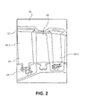
- HPC 52 may comprise alternating rows of rotating rotors 64 and stationary stators 66 (shown as stator 66-1 and stator 66-2 in FIG. 2 ).
- Stators may have a cantilevered configuration or a shrouded configuration.
- Stators 66 have a shrouded configuration as shown in FIG. 2 .
- stator 66 may comprise a stator vane 65, a casing support and a hub support.
- stator vane 65 may be supported along an outer diameter by casing support and along an inner diameter hub support.
- a cantilevered stator may comprise a stator vane that is only retained and/or supported at the casing (e.g., an outer diameter).
- rotors 64 may be configured to compress and spin fluid flow (e.g., core flow C as discussed with reference to FIG. 1 ).
- Stators 66 may be configured to receive and straighten the fluid flow (e.g., core flow C).
- the fluid flow discharged from the trailing edge of stators 66 may be straightened (e.g., the flow may be directed in a substantially parallel path to the centerline of the engine and/or HPC) to increase and/or improve the efficiency of the engine and, more specifically, to achieve maximum compression and efficiency when the straightened air is compressed and spun by rotor 64.
- operating conditions in the aft stages of HPC 52 may be approximately 1400°F (approximately 760°C) or more.
- This increase in core temperature and core flow C may cause the temperature at stator shroud 63 to increase to a temperature that may be higher than the temperature of core flow C.
- the temperature increase may be caused by windage. Windage may be the frictional force between two objects caused by the relative motion between the two objects (e.g., the friction caused between the spinning air and the stationary shroud).
- windage can cause an increase in the temperature of shroud 63 of approximately 100 °F (approximately 56 °C) or more. As a result, windage may cause temperatures in shroud 63 to be approximately 1500 °F (approximately 816 °C) or more. This operating environment may exceed the temperature limit for materials used for HPC components and/or reduce the endurance life of HPC components.
- core flow C may be straightened by stator 66.
- the straightened core flow C may be drawn into cavity 69 aft of stator 66 as shroud flow D.
- Shroud flow D may be "re-spun-up" as shroud flow D moves forward in channel 69 defined between a cavity wall 68 and shroud 63.
- Shroud flow D may cause windage along cavity wall 68 and/or shroud 63.
- Shroud flow D may also cause the pressure and/or temperature in channel 69 to increase.
- shroud flow D may be temporarily trapped in channel 69 for a period of time leading to further increases in pressure and temperature.
- shroud flow D may be ingested back into the main air stream at a forward portion of channel 69, which may create an efficiency penalty.
- HPC 52 may comprise a thermal shield 72.
- Thermal shield 72 may be configured to isolate the shroud flow D from a rotor hub 70.
- thermal shield 72 may define a portion of channel 69.
- thermal shield may include and/or define cavity wall 68.
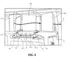
- Thermal shield 72 may also comprise one or more knife seals 74 (shown as first knife seal-1, second knife seal 74-2, and third knife seal 74-3 in FIG. 4 ). Knife seals 74 may be formed in thermal shield 72 (e.g. the body of thermal shield 72).
- knife seals 74 may contact and/or otherwise minimize the flow past shroud 63 of stator 66.
- an edge of knife seal 74 may be configured to contact a surface of shroud 63 to create a seal.
- thermal shield 72 may couple to a first rotor 64-1 and second rotor 64-2.
- Rotor hub 70 may comprise one or more cooling passages 73 that are configured to conduct a cooling flow E from an aft portion of the HPC to a forward portion of the HPC.
- Thermal shield 72 may be configured to define a cooling flow channel 71. Cooling flow channel 71 may be defined between cavity wall 68 and rotor hub 70. Moreover, cooling flow channel 71 may be in fluid communication with one or more cooling passages 73. In this regard, cooling flow channel 71 may be configured to create an insulating fluid layer (e.g., cooling flow E) between rotor hub 70 and thermal shield 72 - shroud flow D.
- an insulating fluid layer e.g., cooling flow E
- cooling flow channel 71 and/or cooling flow E may thermally isolate thermal shield 72 - shroud flow D from rotor hub 70.
- the thermal isolation and/or reduced thermal load created by thermal shield 72 may allow for a reduced size of channel 69, reduced mass of rotor hub 70, reduced temperature gradients in rotor hub 70.
- thermal shield 72 may be a continuous ring. Thermal shield 72 may be installed between and coupled to a first rotor 64-1 and a second rotor 64-2 in an axial manner similar to conventional rotor stack assembly techniques. Thermal shield 72 may be integral with the rotor assembly, allowing for traditional assembly such as the split case design with integral shrouded stators. In this regard, thermal shield 72 may be adapted to existing HPC configurations.
- thermal shield 72 may be retained to first rotor 64-1 and second rotor 64-2 in a number of different ways.
- rotor hub 70 may comprise a suitable retentions mechanism such as, for example, one or more dovetail grooves 76 (shown as dovetail groove 76-1, dovetail groove 76-2, dovetail groove 76-3, and dovetail groove 76-4 in FIGs. 6A and 6B ) disposed about an outer diameter of rotor hub 70.
- Thermal shield 72 may comprise one or more dovetail tabs 78 (shown as dovetail tab 78-1, dovetail tab 78-2, dovetail tab 78-3, and dovetail tab 78-4 in FIGs.
- dovetail tabs 78 may be formed in the body of thermal shield 72.
- the dovetail tab 78 to dovetail groove 76 retention mechanism may define a dovetail union 79.
- Dovetail union 79 may sufficiently retain and support thermal shield 72.
- Thermal shield 72 and/or dovetail union 79 may only be required to bear and/or support the dynamic load and/or dynamic hoop stress of thermal shield 72 as it rotates.
- thermal shield 72 may be made in a lightweight manner since it is not required to absorb any loads other than its own dynamic hoop stresses (e.g., the load as thermal shield 72 rotates).
- Dovetail union 79 may also provide an overall net reduction in weight of the HPC. More specifically, thermal shield 72 may reduce the thermal load on rotor hub 70 allowing rotor hub 70 to be lighter.
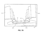
- Rotor hub 70 may comprise a retention mechanism such as, for example, one or more first interlocking arms 80 (shown as first interlocking arm 80-1 and first interlocking arm 80-2 in FIG. 7A ).
- First interlocking arms 80 may be disposed on a portion of an outer diameter of rotor hub 70.
- Thermal shield 72 may be configured with one or more second interlocking arms 82 (shown as second interlocking arm 82-1 and second interlocking arm 82-2 in FIG. 7A ).
- second interlocking arms 82 may be formed in the body of thermal shield 72.
- Second interlocking arms 82 may be disposed on a portion of an inner diameter of thermal shield 72.
- First interlocking arm 80 may correspond to and/or be configured to couple to second interlocking arm 82.
- first interlocking arms 80 may be coupled to and/or mated to second interlocking arms 82, coupling thermal shield 72 to rotor hub 70.
- the coupling of first interlocking arms 80 and second interlocking arms 82 may reduce and/or minimize radial deflection of thermal shield 72 in operation (e.g., when the rotor hub is rotating).
- thermal shield 72 may be axially constrained and/or sandwiched between rotor 64-1 and rotor 64-2.
- thermal shield 72 can be attached to rotor hub 70 by a number of techniques including, for example, welding, brazing, dovetail joints, tabs, or any other mechanical fixation method. Regardless of the fixation method, thermal shield 72 may feature thermal isolation and / or cooling passages which may be formed by features including but not limited to annular gaps, slots, holes, notches, material scallops, or any other shape of passage design.
- thermal shield 72 may be mounted rigidly and/or integrally with rotor hub 70.
- thermal shield 72 may be attached and/or couple to rotor hub 70 (e.g., welded, friction welding, stir welded, tack welded, brazed, glued and/or the like).
- thermal shield 72 may be thermal buffer zone.
- a hybrid-material design may be used.
- thermal shield 72 may be made of one material that has thermal shielding properties, and rotor hub 70 may be made from another material have sufficient strength and heat load tolerance capabilities for and HPC.
- thermal shield 72 may be retained, attached and/or mounted to rotor 64 and/or rotor hub 70 by any suitable method.
- thermal shield 72 may be retained on rotor 64 and/or rotor hub 70 by hooks, slots, fasteners, welding, brazing, and/or the like.
- the retention method may generally reduce and/or minimize radial separation of thermal shield 72 from rotor 64 and/or rotor hub 70 at high rotational speeds (e.g., during operation of the HPC).
- references to "various embodiments”, “one embodiment”, “an embodiment”, “an example embodiment”, etc. indicate that the embodiment described may include a particular feature, structure, or characteristic, but every embodiment may not necessarily include the particular feature, structure, or characteristic. Moreover, such phrases are not necessarily referring to the same embodiment. Further, when a particular feature, structure, or characteristic is described in connection with an embodiment, it is submitted that it is within the knowledge of one skilled in the art to affect such feature, structure, or characteristic in connection with other embodiments whether or not explicitly described. After reading the description, it will be apparent to one skilled in the relevant art(s) how to implement the disclosure in alternative embodiments.
Landscapes
- Engineering & Computer Science (AREA)
- Mechanical Engineering (AREA)
- General Engineering & Computer Science (AREA)
- Chemical & Material Sciences (AREA)
- Combustion & Propulsion (AREA)
- Structures Of Non-Positive Displacement Pumps (AREA)
Abstract
Description
- The present disclosure relates to thermal protection system for high pressure compressor components, and, more specifically, to a thermal shield configured to conduct cooling airflow through one or more portions of a high pressure compressor.
- Modem turbofan engines have a modular design architecture consisting of the "cold section" and "hot section." Air drawn in to the engine undergoes an increase in pressure through the cold section, followed by a decrease in pressure through the hot section as work is extracted from the compressed air. Typically, the air temperature increases through each stage of the engine.
- In various embodiments, a thermal shield may comprise a body portion, a retention mechanism and a first knife seal. The retention mechanism may be integrally formed in the body portion. The first knife seal may be integrally formed in the body portion. The thermal shield may be installable within a high pressure compressor. The retention mechanism may be configured to couple the body portion to a rotor hub. Lateral motion of the body portion may be restrained by a first rotor and a second rotor of a high pressure compressor.
- In various embodiments, a high pressure compressor may comprise a rotor hub, a first rotor, a stator, a second rotor and a thermal shield. The first rotor may be coupled to the rotor hub. The stator may be installed adjacent to and aft the first rotor. The second rotor may be installed adjacent to and aft the stator. The second rotor may be coupled to the rotor hub. The thermal shield may be coupled to the rotor hub. The thermal shield may be disposed radially inward of the stator. The thermal shield may also comprise one or more seals including, for example, one or more knife seals.
- In various embodiments, a gas turbine engine may comprise a high pressure turbine, a combustor and a high pressure compressor. The combustor may be configured to drive the high pressure turbine. The high pressure compressor may be operatively coupled to the high pressure turbine. The high pressure compressor may be capable of being driven by the high pressure turbine. The high pressure compressor may comprise a rotor hub, a first rotor, a second rotor, and a thermal shield. The first rotor may be coupled to the rotor hub. The second rotor may be installed adjacent and aft the first rotor. The thermal shield may be coupled to the rotor hub and disposed between the first rotor and the second rotor. The thermal shield may comprise one or more seals, including, at least a first seal and the second seal. The first seal may be, for example, a first knife seal and the second seal may be, for example, a second knife seal.
- The forgoing features and elements may be combined in various combinations without exclusivity, unless expressly indicated herein otherwise. These features and elements as well as the operation of the disclosed embodiments will become more apparent in light of the following description and accompanying drawings.
- The subject matter of the present disclosure is particularly pointed out and distinctly claimed in the concluding portion of the specification. A more complete understanding of the present disclosure, however, may best be obtained by referring to the detailed description and claims when considered in connection with the drawing figures, wherein like numerals denote like elements.
-
FIG. 1 illustrates cross-sectional view of an exemplary gas turbine engine, in accordance with various embodiments; -
FIG. 2 illustrates a cross-sectional view of a portion of a high pressure compressor comprising a shrouded stator, in accordance with various embodiments; -
FIG. 3 is a schematic showing fluid flow around a shrouded stator, in accordance with various embodiments; -
FIG. 4 illustrates a perspective cross-sectional view of a portion of a high pressure compressor comprising a thermal shield, in accordance with various embodiments; -
FIG. 5 illustrates an exploded perspective view of a portion of a high pressure compressor comprising a thermal shield, in accordance with various embodiments; -
FIG. 6A - 6B illustrate a portion of a high pressure compressor comprising a thermal shield having a dovetail union, in accordance with various embodiments; -
FIG. 7A - 7B illustrate a portion of a high pressure compressor comprising a thermal shield having an interlocking arm joint, in accordance with various embodiments; and -
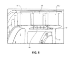
FIG. 8 illustrates a portion of a high pressure compressor comprising a thermal shield coupled to a rotor hub, in accordance with various embodiments. - The detailed description of exemplary embodiments herein makes reference to the accompanying drawings, which show exemplary embodiments by way of illustration. While these exemplary embodiments are described in sufficient detail to enable those skilled in the art to practice the inventions, it should be understood that other embodiments may be realized and that logical changes and adaptations in design and construction may be made in accordance with this invention and the teachings herein. Thus, the detailed description herein is presented for purposes of illustration only and not of limitation. The scope of the invention is defined by the appended claims. For example, the steps recited in any of the method or process descriptions may be executed in any order and are not necessarily limited to the order presented. Furthermore, any reference to singular includes plural embodiments, and any reference to more than one component or step may include a singular embodiment or step. Also, any reference to attached, fixed, connected or the like may include permanent, removable, temporary, partial, full and/or any other possible attachment option. Additionally, any reference to without contact (or similar phrases) may also include reduced contact or minimal contact.
- Furthermore, any reference to singular includes plural embodiments, and any reference to more than one component or step may include a singular embodiment or step. Surface shading lines may be used throughout the figures to denote different parts but not necessarily to denote the same or different materials.
- As used herein, "aft" refers to the direction associated with the tail (e.g., the back end) of an aircraft, or generally, to the direction of exhaust of the gas turbine. As used herein, "forward" refers to the direction associated with the nose (e.g., the front end) of an aircraft, or generally, to the direction of flight or motion.
- In various embodiments and with reference to
FIG. 1 , agas turbine engine 20 is provided.Gas turbine engine 20 may be a two-spool turbofan that generally incorporates afan section 22, acompressor section 24, acombustor section 26 and aturbine section 28. Alternative engines may include, for example, an augmentor section among other systems or features. In operation,fan section 22 can drive air along a bypass flow-path B whilecompressor section 24 can drive air along a core flow-path C for compression and communication intocombustor section 26 then expansion throughturbine section 28. Although depicted as a turbofangas turbine engine 20 herein, it should be understood that the concepts described herein are not limited to use with turbofans as the teachings may be applied to other types of turbine engines including three-spool architectures. -
Gas turbine engine 20 may generally comprise alow speed spool 30 and ahigh speed spool 32 mounted for rotation about an engine central longitudinal axis A-A' relative to an enginestatic structure 36 via one or more bearing systems 38 (shown as bearing system 38-1 and bearing system 38-2 inFIG. 1 ). It should be understood that various bearingsystems 38 at various locations may alternatively or additionally be provided, including for example, bearingsystem 38, bearing system 38-1, and bearing system 38-2. -
Low speed spool 30 may generally comprise aninner shaft 40 that interconnects afan 42, a low pressure (or first)compressor section 44 and a low pressure (or first)turbine section 46.Inner shaft 40 may be connected to fan 42 through a geared architecture 48 that can drivefan 42 at a lower speed thanlow speed spool 30. Geared architecture 48 may comprise agear assembly 60 enclosed within agear housing 62.Gear assembly 60 couplesinner shaft 40 to a rotating fan structure.High speed spool 32 may comprise anouter shaft 50 that interconnects a high pressure compressor ("HPC") 52 (e.g., a second compressor section) and high pressure (or second)turbine section 54. Acombustor 56 may be located betweenHPC 52 andhigh pressure turbine 54. Amid-turbine frame 57 of enginestatic structure 36 may be located generally betweenhigh pressure turbine 54 andlow pressure turbine 46.Mid-turbine frame 57 may support one ormore bearing systems 38 inturbine section 28.Inner shaft 40 andouter shaft 50 may be concentric and rotate via bearingsystems 38 about the engine central longitudinal axis A-A', which is collinear with their longitudinal axes. As used herein, a "high pressure" compressor or turbine experiences a higher pressure than a corresponding "low pressure" compressor or turbine. - The core airflow C may be compressed by
low pressure compressor 44 thenHPC 52, mixed and burned with fuel incombustor 56, then expanded overhigh pressure turbine 54 andlow pressure turbine 46.Mid-turbine frame 57 includesairfoils 59 which are in the core airflow path.Low pressure turbine 46, andhigh pressure turbine 54 rotationally drive the respectivelow speed spool 30 andhigh speed spool 32 in response to the expansion. -
Gas turbine engine 20 may be, for example, a high-bypass geared aircraft engine. In various embodiments, the bypass ratio ofgas turbine engine 20 may be greater than about six (6). In various embodiments, the bypass ratio ofgas turbine engine 20 may be greater than ten (10). In various embodiments, geared architecture 48 may be an epicyclic gear train, such as a star gear system (sun gear in meshing engagement with a plurality of star gears supported by a carrier and in meshing engagement with a ring gear) or other gear system. Geared architecture 48 may have a gear reduction ratio of greater than about 2.3 andlow pressure turbine 46 may have a pressure ratio that is greater than about 5. In various embodiments, the bypass ratio ofgas turbine engine 20 is greater than about ten (10:1). In various embodiments, the diameter offan 42 may be significantly larger than that of thelow pressure compressor 44, and thelow pressure turbine 46 may have a pressure ratio that is greater than about 5:1.Low pressure turbine 46 pressure ratio may be measured prior to inlet oflow pressure turbine 46 as related to the pressure at the outlet oflow pressure turbine 46 prior to an exhaust nozzle. It should be understood, however, that the above parameters are exemplary of various embodiments of a suitable geared architecture engine and that the present disclosure contemplates other gas turbine engines including direct drive turbofans. - In various embodiments, the next generation of turbofan engines may be designed for higher efficiency which requires higher pressure ratios and higher temperatures in the
HPC 52. These higher operating temperatures and pressure ratios may create operating environments that may cause thermal loads that are higher than the thermal loads which may shorten the endurance life of current components. - In various embodiments and with reference to
FIG. 2 ,HPC 52 may comprise alternating rows ofrotating rotors 64 and stationary stators 66 (shown as stator 66-1 and stator 66-2 inFIG. 2 ). Stators may have a cantilevered configuration or a shrouded configuration.Stators 66 have a shrouded configuration as shown inFIG. 2 . More specifically,stator 66 may comprise astator vane 65, a casing support and a hub support. In this regard,stator vane 65 may be supported along an outer diameter by casing support and along an inner diameter hub support. In contrast, a cantilevered stator may comprise a stator vane that is only retained and/or supported at the casing (e.g., an outer diameter). - In various embodiments,
rotors 64 may be configured to compress and spin fluid flow (e.g., core flow C as discussed with reference toFIG. 1 ).Stators 66 may be configured to receive and straighten the fluid flow (e.g., core flow C). In operation, the fluid flow discharged from the trailing edge ofstators 66 may be straightened (e.g., the flow may be directed in a substantially parallel path to the centerline of the engine and/or HPC) to increase and/or improve the efficiency of the engine and, more specifically, to achieve maximum compression and efficiency when the straightened air is compressed and spun byrotor 64. - In various embodiments and with reference to
FIG. 3 , operating conditions in the aft stages ofHPC 52 may be approximately 1400°F (approximately 760°C) or more. This increase in core temperature and core flow C may cause the temperature atstator shroud 63 to increase to a temperature that may be higher than the temperature of core flow C. The temperature increase may be caused by windage. Windage may be the frictional force between two objects caused by the relative motion between the two objects (e.g., the friction caused between the spinning air and the stationary shroud). - In various embodiments, windage can cause an increase in the temperature of
shroud 63 of approximately 100 °F (approximately 56 °C) or more. As a result, windage may cause temperatures inshroud 63 to be approximately 1500 °F (approximately 816 °C) or more. This operating environment may exceed the temperature limit for materials used for HPC components and/or reduce the endurance life of HPC components. - In various embodiments and with reference to
FIG. 3 , core flow C may be straightened bystator 66. The straightened core flow C may be drawn intocavity 69 aft ofstator 66 as shroud flow D. Shroud flow D may be "re-spun-up" as shroud flow D moves forward inchannel 69 defined between acavity wall 68 andshroud 63. Shroud flow D may cause windage alongcavity wall 68 and/orshroud 63. Shroud flow D may also cause the pressure and/or temperature inchannel 69 to increase. In this regard, shroud flow D may be temporarily trapped inchannel 69 for a period of time leading to further increases in pressure and temperature. Moreover, shroud flow D may be ingested back into the main air stream at a forward portion ofchannel 69, which may create an efficiency penalty. - In various embodiments and with reference to
FIG. 4 ,HPC 52 may comprise athermal shield 72.Thermal shield 72 may be configured to isolate the shroud flow D from arotor hub 70. In this regard,thermal shield 72 may define a portion ofchannel 69. Moreover, thermal shield may include and/or definecavity wall 68.Thermal shield 72 may also comprise one or more knife seals 74 (shown as first knife seal-1, second knife seal 74-2, and third knife seal 74-3 inFIG. 4 ). Knife seals 74 may be formed in thermal shield 72 (e.g. the body of thermal shield 72). Moreover, knife seals 74 may contact and/or otherwise minimize the flow pastshroud 63 ofstator 66. For example, an edge of knife seal 74 may be configured to contact a surface ofshroud 63 to create a seal. - In various embodiments,
thermal shield 72 may couple to a first rotor 64-1 and second rotor 64-2.Rotor hub 70 may comprise one or more cooling passages 73 that are configured to conduct a cooling flow E from an aft portion of the HPC to a forward portion of the HPC.Thermal shield 72 may be configured to define acooling flow channel 71.Cooling flow channel 71 may be defined betweencavity wall 68 androtor hub 70. Moreover, coolingflow channel 71 may be in fluid communication with one or more cooling passages 73. In this regard, coolingflow channel 71 may be configured to create an insulating fluid layer (e.g., cooling flow E) betweenrotor hub 70 and thermal shield 72 - shroud flow D. In this regard, coolingflow channel 71 and/or cooling flow E may thermally isolate thermal shield 72 - shroud flow D fromrotor hub 70. In this regard, the thermal isolation and/or reduced thermal load created bythermal shield 72 may allow for a reduced size ofchannel 69, reduced mass ofrotor hub 70, reduced temperature gradients inrotor hub 70. - In various embodiments and with reference to
FIG. 5 ,thermal shield 72 may be a continuous ring.Thermal shield 72 may be installed between and coupled to a first rotor 64-1 and a second rotor 64-2 in an axial manner similar to conventional rotor stack assembly techniques.Thermal shield 72 may be integral with the rotor assembly, allowing for traditional assembly such as the split case design with integral shrouded stators. In this regard,thermal shield 72 may be adapted to existing HPC configurations. - In various embodiments,
thermal shield 72 may be retained to first rotor 64-1 and second rotor 64-2 in a number of different ways. For example and with reference toFIGs. 6A and6B ,rotor hub 70 may comprise a suitable retentions mechanism such as, for example, one or more dovetail grooves 76 (shown as dovetail groove 76-1, dovetail groove 76-2, dovetail groove 76-3, and dovetail groove 76-4 inFIGs. 6A and6B ) disposed about an outer diameter ofrotor hub 70.Thermal shield 72 may comprise one or more dovetail tabs 78 (shown as dovetail tab 78-1, dovetail tab 78-2, dovetail tab 78-3, and dovetail tab 78-4 inFIGs. 6A and6B ) disposed about an inner diameter ofthermal shield 72. In this regard, dovetail tabs 78 may be formed in the body ofthermal shield 72. The dovetail tab 78 to dovetail groove 76 retention mechanism may define adovetail union 79. -
Dovetail union 79 may sufficiently retain and supportthermal shield 72.Thermal shield 72 and/ordovetail union 79 may only be required to bear and/or support the dynamic load and/or dynamic hoop stress ofthermal shield 72 as it rotates. In this regard,thermal shield 72 may be made in a lightweight manner since it is not required to absorb any loads other than its own dynamic hoop stresses (e.g., the load asthermal shield 72 rotates).Dovetail union 79 may also provide an overall net reduction in weight of the HPC. More specifically,thermal shield 72 may reduce the thermal load onrotor hub 70 allowingrotor hub 70 to be lighter. - In various embodiments and with reference to
FIGs. 7A-7B ,Rotor hub 70 may comprise a retention mechanism such as, for example, one or more first interlocking arms 80 (shown as first interlocking arm 80-1 and first interlocking arm 80-2 inFIG. 7A ). First interlocking arms 80 may be disposed on a portion of an outer diameter ofrotor hub 70.Thermal shield 72 may be configured with one or more second interlocking arms 82 (shown as second interlocking arm 82-1 and second interlocking arm 82-2 inFIG. 7A ). In this regard, second interlocking arms 82 may be formed in the body ofthermal shield 72. Second interlocking arms 82 may be disposed on a portion of an inner diameter ofthermal shield 72. First interlocking arm 80 may correspond to and/or be configured to couple to second interlocking arm 82. During assembly, first interlocking arms 80 may be coupled to and/or mated to second interlocking arms 82, couplingthermal shield 72 torotor hub 70. The coupling of first interlocking arms 80 and second interlocking arms 82 may reduce and/or minimize radial deflection ofthermal shield 72 in operation (e.g., when the rotor hub is rotating). Moreover,thermal shield 72 may be axially constrained and/or sandwiched between rotor 64-1 and rotor 64-2. - In various embodiments,
thermal shield 72 can be attached torotor hub 70 by a number of techniques including, for example, welding, brazing, dovetail joints, tabs, or any other mechanical fixation method. Regardless of the fixation method,thermal shield 72 may feature thermal isolation and / or cooling passages which may be formed by features including but not limited to annular gaps, slots, holes, notches, material scallops, or any other shape of passage design. - In various embodiments and with reference to
FIG. 8 ,thermal shield 72 may be mounted rigidly and/or integrally withrotor hub 70. For example,thermal shield 72 may be attached and/or couple to rotor hub 70 (e.g., welded, friction welding, stir welded, tack welded, brazed, glued and/or the like). In this regard,thermal shield 72 may be thermal buffer zone. In various embodiments, a hybrid-material design may be used. For example,thermal shield 72 may be made of one material that has thermal shielding properties, androtor hub 70 may be made from another material have sufficient strength and heat load tolerance capabilities for and HPC. - In various embodiments,
thermal shield 72 may be retained, attached and/or mounted torotor 64 and/orrotor hub 70 by any suitable method. For example,thermal shield 72 may be retained onrotor 64 and/orrotor hub 70 by hooks, slots, fasteners, welding, brazing, and/or the like. In this regard, the retention method may generally reduce and/or minimize radial separation ofthermal shield 72 fromrotor 64 and/orrotor hub 70 at high rotational speeds (e.g., during operation of the HPC). - Benefits, other advantages, and solutions to problems have been described herein with regard to specific embodiments. Furthermore, the connecting lines shown in the various figures contained herein are intended to represent exemplary functional relationships and/or physical couplings between the various elements. It should be noted that many alternative or additional functional relationships or physical connections may be present in a practical system. However, the benefits, advantages, solutions to problems, and any elements that may cause any benefit, advantage, or solution to occur or become more pronounced are not to be construed as critical, required, or essential features or elements of the inventions. The scope of the inventions is accordingly to be limited by nothing other than the appended claims, in which reference to an element in the singular is not intended to mean "one and only one" unless explicitly so stated, but rather "one or more." Moreover, where a phrase similar to "at least one of A, B, or C" is used in the claims, it is intended that the phrase be interpreted to mean that A alone may be present in an embodiment, B alone may be present in an embodiment, C alone may be present in an embodiment, or that any combination of the elements A, B and C may be present in a single embodiment; for example, A and B, A and C, B and C, or A and B and C.
- Systems, methods and apparatus are provided herein. In the detailed description herein, references to "various embodiments", "one embodiment", "an embodiment", "an example embodiment", etc., indicate that the embodiment described may include a particular feature, structure, or characteristic, but every embodiment may not necessarily include the particular feature, structure, or characteristic. Moreover, such phrases are not necessarily referring to the same embodiment. Further, when a particular feature, structure, or characteristic is described in connection with an embodiment, it is submitted that it is within the knowledge of one skilled in the art to affect such feature, structure, or characteristic in connection with other embodiments whether or not explicitly described. After reading the description, it will be apparent to one skilled in the relevant art(s) how to implement the disclosure in alternative embodiments.
- Furthermore, no element, component, or method step in the present disclosure is intended to be dedicated to the public regardless of whether the element, component, or method step is explicitly recited in the claims. No claim element herein is to be construed under the provisions of 35 U.S.C. 112, sixth paragraph, unless the element is expressly recited using the phrase "means for." As used herein, the terms "comprises", "comprising", or any other variation thereof, are intended to cover a non-exclusive inclusion, such that a process, method, article, or apparatus that comprises a list of elements does not include only those elements but may include other elements not expressly listed or inherent to such process, method, article, or apparatus.
Claims (15)
- A high pressure compressor (52), comprising:a rotor hub (70);a first rotor (64-1) coupled to the rotor hub (70);a stator (66) adjacent and aft the first rotor (64-1);a second rotor (64-2) adjacent and aft the stator (66), the second rotor (64-2) coupled to the rotor hub (70); anda thermal shield (72) coupled to the rotor hub (70) and disposed radially inward of the stator (60), the thermal shield (72) comprising a knife seal (74).
- The high pressure compressor of claim 1, wherein the knife seal (74) is configured to minimize flow below the stator (66).
- The high pressure compressor of claim 1 or 2, wherein the knife seal (74) is configured to reduce windage.
- The high pressure compressor of claim 1, 2 or 3, wherein the thermal shield (72) is bonded to the rotor hub (70), or alternatively coupled to the rotor hub (70) with at least one of an interlocking arm (60,62) and a dovetail union (79).
- The high pressure compressor of any preceding claim, wherein a cooling channel (71) is disposed between and defined by the thermal shield (72) and the rotor hub (70).
- The high pressure compressor of claim 5, wherein the cooling channel is in fluid communication with a cooling port disposed in the second rotor (64-2).
- The high pressure compressor of claim 5 or 6, wherein the cooling channel (71) is configured to reduce the thermal load in the rotor hub (70).
- The high pressure compressor of any preceding claim, wherein the first rotor (64-1) and the second rotor (64-2) are configured to restrain motion of the thermal shield (72).
- The high pressure compressor of any preceding claim, wherein the thermal shield (72) is a first material and the rotor hub (70) is a second material.
- A gas turbine engine (20) comprising:a high pressure turbine (54);a combustor (56) configured to drive the high pressure turbine (54);a high pressure compressor (52) operatively coupled to the high pressure turbine (54) and capable of being driven by the high pressure turbine (54), the high pressure compressor (52), comprising,a rotor hub (70);a first rotor (64-1) coupled to the rotor hub (70);a second rotor (64-2) adjacent and aft the first rotor (64-1); anda thermal shield (72) coupled to the rotor hub (70) and disposed between the first rotor (64-1) and the second rotor (64-2), the thermal shield (72) comprising at least a first knife seal (74-1) and a second knife seal (74-2).
- The gas turbine engine of claim 10, wherein the thermal shield (72) is configured to thermally isolate the rotor hub (70) from a shroud flow (D), wherein, optionally, the thermal shield defines a cooling channel (71) to isolate the rotor hub (70) from the shroud flow (D).
- The gas turbine engine of claim 10 or 11, further comprising a shrouded stator (66) disposed between the first rotor (64-1) and the second rotor (64-2), wherein the thermal shield (72) is disposed radially inward of the shrouded stator (66).
- A thermal shield (72), comprising:a body portion;a retention mechanism integrally formed in the body portion; anda first knife seal (74) integrally formed in the body portion.
- The thermal shield of claim 13, further comprising a plurality of knife seals (73-1 to 74-3).
- The thermal shield of claim 13 or 14, wherein the retention mechanism is at least one of a dovetail retention mechanism (79) and an interlocking arm retention mechanism (80,82).
Applications Claiming Priority (1)
| Application Number | Priority Date | Filing Date | Title |
|---|---|---|---|
| US201461978637P | 2014-04-11 | 2014-04-11 |
Publications (2)
| Publication Number | Publication Date |
|---|---|
| EP2930304A1 true EP2930304A1 (en) | 2015-10-14 |
| EP2930304B1 EP2930304B1 (en) | 2017-11-29 |
Family
ID=53269293
Family Applications (1)
| Application Number | Title | Priority Date | Filing Date |
|---|---|---|---|
| EP15163327.8A Active EP2930304B1 (en) | 2014-04-11 | 2015-04-13 | High pressure compressor thermal shield apparatus and system |
Country Status (2)
| Country | Link |
|---|---|
| US (1) | US10036278B2 (en) |
| EP (1) | EP2930304B1 (en) |
Citations (4)
| Publication number | Priority date | Publication date | Assignee | Title |
|---|---|---|---|---|
| US3056579A (en) * | 1959-04-13 | 1962-10-02 | Gen Electric | Rotor construction |
| EP1079070A2 (en) * | 1999-08-26 | 2001-02-28 | Asea Brown Boveri Ag | Heatshield for a turbine rotor |
| US20020187046A1 (en) * | 2001-06-07 | 2002-12-12 | Snecma Moteurs | Turbomachine rotor assembly with two bladed-discs separated by a spacer |
| US20070235946A9 (en) * | 2004-05-28 | 2007-10-11 | Garrison Glenn M | Air riding seal |
Family Cites Families (12)
| Publication number | Priority date | Publication date | Assignee | Title |
|---|---|---|---|---|
| FR2404134A1 (en) * | 1977-09-23 | 1979-04-20 | Snecma | ROTOR FOR TURBOMACHINES |
| GB2307520B (en) * | 1995-11-14 | 1999-07-07 | Rolls Royce Plc | A gas turbine engine |
| DE19615549B8 (en) * | 1996-04-19 | 2005-07-07 | Alstom | Device for thermal protection of a rotor of a high-pressure compressor |
| FR2834751B1 (en) * | 2002-01-17 | 2004-09-10 | Snecma Moteurs | ROTOR ARRANGEMENT OF A TURBOMACHINE |
| DE102004007327A1 (en) * | 2004-02-14 | 2005-09-15 | Alstom Technology Ltd | rotor |
| US8573940B2 (en) * | 2006-07-07 | 2013-11-05 | United Technologies Corporation | Interlocking knife edge seals |
| EP1898054B1 (en) * | 2006-08-25 | 2018-05-30 | Ansaldo Energia IP UK Limited | Gas turbine |
| EP2039886B1 (en) * | 2007-09-24 | 2010-06-23 | ALSTOM Technology Ltd | Seal in gas turbine |
| FR2940768B1 (en) * | 2009-01-06 | 2013-07-05 | Snecma | PROCESS FOR MANUFACTURING TURBOMACHINE COMPRESSOR DRUM |
| US8328507B2 (en) * | 2009-05-15 | 2012-12-11 | United Technologies Corporation | Knife edge seal assembly |
| FR2960604B1 (en) * | 2010-05-26 | 2013-09-20 | Snecma | COMPRESSOR BLADE ASSEMBLY OF TURBOMACHINE |
| US8511976B2 (en) * | 2010-08-02 | 2013-08-20 | General Electric Company | Turbine seal system |
-
2015
- 2015-03-23 US US14/665,797 patent/US10036278B2/en active Active
- 2015-04-13 EP EP15163327.8A patent/EP2930304B1/en active Active
Patent Citations (4)
| Publication number | Priority date | Publication date | Assignee | Title |
|---|---|---|---|---|
| US3056579A (en) * | 1959-04-13 | 1962-10-02 | Gen Electric | Rotor construction |
| EP1079070A2 (en) * | 1999-08-26 | 2001-02-28 | Asea Brown Boveri Ag | Heatshield for a turbine rotor |
| US20020187046A1 (en) * | 2001-06-07 | 2002-12-12 | Snecma Moteurs | Turbomachine rotor assembly with two bladed-discs separated by a spacer |
| US20070235946A9 (en) * | 2004-05-28 | 2007-10-11 | Garrison Glenn M | Air riding seal |
Also Published As
| Publication number | Publication date |
|---|---|
| EP2930304B1 (en) | 2017-11-29 |
| US10036278B2 (en) | 2018-07-31 |
| US20150292353A1 (en) | 2015-10-15 |
Similar Documents
| Publication | Publication Date | Title |
|---|---|---|
| US10533446B2 (en) | Alternative W-seal groove arrangement | |
| US10724440B2 (en) | Compressor injector apparatus and system | |
| EP3578780A1 (en) | Dual direction windmill pump for geared turbofan engines | |
| US9803489B2 (en) | Low loss baffled serpentine turns | |
| US9896969B2 (en) | Zero or low leakage oil transfer bearing | |
| US9759078B2 (en) | Airfoil module | |
| EP3026217B1 (en) | Turbine rotor or stator segmented sideplates with anti-rotation | |
| EP3546700A1 (en) | Double bore basket | |
| EP3388624A1 (en) | Airfoil, engine section and gas turbine engine | |
| EP3569818A1 (en) | Support ring with thermal heat shield for case flanges | |
| EP3081748B1 (en) | Gas turbine engine system comprising a seal ring | |
| EP3748134B1 (en) | Vane airfoil shapes for embedded members | |
| EP3730828B1 (en) | Dynamic sleeve seal fittings | |
| EP2930304B1 (en) | High pressure compressor thermal shield apparatus and system | |
| EP3112602B1 (en) | Break-in system for gapping and leakage control | |
| US11408300B2 (en) | Rotor overspeed protection assembly | |
| EP3470685A1 (en) | Gap closing wearliner | |
| EP3623578A1 (en) | Gas turbine blade with dirt removal holes | |
| EP3101232A1 (en) | Rotor disk, corresponding assembly and gas turbine engine | |
| EP3628821A1 (en) | Vane platform leading edge recessed pocket with cover |
Legal Events
| Date | Code | Title | Description |
|---|---|---|---|
| PUAI | Public reference made under article 153(3) epc to a published international application that has entered the european phase |
Free format text: ORIGINAL CODE: 0009012 |
|
| AK | Designated contracting states |
Kind code of ref document: A1 Designated state(s): AL AT BE BG CH CY CZ DE DK EE ES FI FR GB GR HR HU IE IS IT LI LT LU LV MC MK MT NL NO PL PT RO RS SE SI SK SM TR |
|
| AX | Request for extension of the european patent |
Extension state: BA ME |
|
| 17P | Request for examination filed |
Effective date: 20160414 |
|
| RBV | Designated contracting states (corrected) |
Designated state(s): AL AT BE BG CH CY CZ DE DK EE ES FI FR GB GR HR HU IE IS IT LI LT LU LV MC MK MT NL NO PL PT RO RS SE SI SK SM TR |
|
| RAP1 | Party data changed (applicant data changed or rights of an application transferred) |
Owner name: UNITED TECHNOLOGIES CORPORATION |
|
| GRAP | Despatch of communication of intention to grant a patent |
Free format text: ORIGINAL CODE: EPIDOSNIGR1 |
|
| STAA | Information on the status of an ep patent application or granted ep patent |
Free format text: STATUS: GRANT OF PATENT IS INTENDED |
|
| INTG | Intention to grant announced |
Effective date: 20170531 |
|
| GRAS | Grant fee paid |
Free format text: ORIGINAL CODE: EPIDOSNIGR3 |
|
| GRAJ | Information related to disapproval of communication of intention to grant by the applicant or resumption of examination proceedings by the epo deleted |
Free format text: ORIGINAL CODE: EPIDOSDIGR1 |
|
| GRAL | Information related to payment of fee for publishing/printing deleted |
Free format text: ORIGINAL CODE: EPIDOSDIGR3 |
|
| STAA | Information on the status of an ep patent application or granted ep patent |
Free format text: STATUS: REQUEST FOR EXAMINATION WAS MADE |
|
| GRAR | Information related to intention to grant a patent recorded |
Free format text: ORIGINAL CODE: EPIDOSNIGR71 |
|
| STAA | Information on the status of an ep patent application or granted ep patent |
Free format text: STATUS: GRANT OF PATENT IS INTENDED |
|
| GRAA | (expected) grant |
Free format text: ORIGINAL CODE: 0009210 |
|
| STAA | Information on the status of an ep patent application or granted ep patent |
Free format text: STATUS: THE PATENT HAS BEEN GRANTED |
|
| INTC | Intention to grant announced (deleted) | ||
| INTG | Intention to grant announced |
Effective date: 20171019 |
|
| AK | Designated contracting states |
Kind code of ref document: B1 Designated state(s): AL AT BE BG CH CY CZ DE DK EE ES FI FR GB GR HR HU IE IS IT LI LT LU LV MC MK MT NL NO PL PT RO RS SE SI SK SM TR |
|
| REG | Reference to a national code |
Ref country code: CH Ref legal event code: EP |
|
| REG | Reference to a national code |
Ref country code: AT Ref legal event code: REF Ref document number: 950583 Country of ref document: AT Kind code of ref document: T Effective date: 20171215 |
|
| REG | Reference to a national code |
Ref country code: IE Ref legal event code: FG4D |
|
| REG | Reference to a national code |
Ref country code: DE Ref legal event code: R096 Ref document number: 602015006262 Country of ref document: DE |
|
| REG | Reference to a national code |
Ref country code: FR Ref legal event code: PLFP Year of fee payment: 4 |
|
| REG | Reference to a national code |
Ref country code: NL Ref legal event code: MP Effective date: 20171129 |
|
| REG | Reference to a national code |
Ref country code: LT Ref legal event code: MG4D |
|
| REG | Reference to a national code |
Ref country code: AT Ref legal event code: MK05 Ref document number: 950583 Country of ref document: AT Kind code of ref document: T Effective date: 20171129 |
|
| PG25 | Lapsed in a contracting state [announced via postgrant information from national office to epo] |
Ref country code: NO Free format text: LAPSE BECAUSE OF FAILURE TO SUBMIT A TRANSLATION OF THE DESCRIPTION OR TO PAY THE FEE WITHIN THE PRESCRIBED TIME-LIMIT Effective date: 20180228 Ref country code: ES Free format text: LAPSE BECAUSE OF FAILURE TO SUBMIT A TRANSLATION OF THE DESCRIPTION OR TO PAY THE FEE WITHIN THE PRESCRIBED TIME-LIMIT Effective date: 20171129 Ref country code: FI Free format text: LAPSE BECAUSE OF FAILURE TO SUBMIT A TRANSLATION OF THE DESCRIPTION OR TO PAY THE FEE WITHIN THE PRESCRIBED TIME-LIMIT Effective date: 20171129 Ref country code: LT Free format text: LAPSE BECAUSE OF FAILURE TO SUBMIT A TRANSLATION OF THE DESCRIPTION OR TO PAY THE FEE WITHIN THE PRESCRIBED TIME-LIMIT Effective date: 20171129 Ref country code: SE Free format text: LAPSE BECAUSE OF FAILURE TO SUBMIT A TRANSLATION OF THE DESCRIPTION OR TO PAY THE FEE WITHIN THE PRESCRIBED TIME-LIMIT Effective date: 20171129 |
|
| PG25 | Lapsed in a contracting state [announced via postgrant information from national office to epo] |
Ref country code: GR Free format text: LAPSE BECAUSE OF FAILURE TO SUBMIT A TRANSLATION OF THE DESCRIPTION OR TO PAY THE FEE WITHIN THE PRESCRIBED TIME-LIMIT Effective date: 20180301 Ref country code: HR Free format text: LAPSE BECAUSE OF FAILURE TO SUBMIT A TRANSLATION OF THE DESCRIPTION OR TO PAY THE FEE WITHIN THE PRESCRIBED TIME-LIMIT Effective date: 20171129 Ref country code: BG Free format text: LAPSE BECAUSE OF FAILURE TO SUBMIT A TRANSLATION OF THE DESCRIPTION OR TO PAY THE FEE WITHIN THE PRESCRIBED TIME-LIMIT Effective date: 20180228 Ref country code: RS Free format text: LAPSE BECAUSE OF FAILURE TO SUBMIT A TRANSLATION OF THE DESCRIPTION OR TO PAY THE FEE WITHIN THE PRESCRIBED TIME-LIMIT Effective date: 20171129 Ref country code: LV Free format text: LAPSE BECAUSE OF FAILURE TO SUBMIT A TRANSLATION OF THE DESCRIPTION OR TO PAY THE FEE WITHIN THE PRESCRIBED TIME-LIMIT Effective date: 20171129 Ref country code: AT Free format text: LAPSE BECAUSE OF FAILURE TO SUBMIT A TRANSLATION OF THE DESCRIPTION OR TO PAY THE FEE WITHIN THE PRESCRIBED TIME-LIMIT Effective date: 20171129 |
|
| PG25 | Lapsed in a contracting state [announced via postgrant information from national office to epo] |
Ref country code: NL Free format text: LAPSE BECAUSE OF FAILURE TO SUBMIT A TRANSLATION OF THE DESCRIPTION OR TO PAY THE FEE WITHIN THE PRESCRIBED TIME-LIMIT Effective date: 20171129 |
|
| PG25 | Lapsed in a contracting state [announced via postgrant information from national office to epo] |
Ref country code: CZ Free format text: LAPSE BECAUSE OF FAILURE TO SUBMIT A TRANSLATION OF THE DESCRIPTION OR TO PAY THE FEE WITHIN THE PRESCRIBED TIME-LIMIT Effective date: 20171129 Ref country code: SK Free format text: LAPSE BECAUSE OF FAILURE TO SUBMIT A TRANSLATION OF THE DESCRIPTION OR TO PAY THE FEE WITHIN THE PRESCRIBED TIME-LIMIT Effective date: 20171129 Ref country code: CY Free format text: LAPSE BECAUSE OF FAILURE TO SUBMIT A TRANSLATION OF THE DESCRIPTION OR TO PAY THE FEE WITHIN THE PRESCRIBED TIME-LIMIT Effective date: 20171129 Ref country code: EE Free format text: LAPSE BECAUSE OF FAILURE TO SUBMIT A TRANSLATION OF THE DESCRIPTION OR TO PAY THE FEE WITHIN THE PRESCRIBED TIME-LIMIT Effective date: 20171129 Ref country code: DK Free format text: LAPSE BECAUSE OF FAILURE TO SUBMIT A TRANSLATION OF THE DESCRIPTION OR TO PAY THE FEE WITHIN THE PRESCRIBED TIME-LIMIT Effective date: 20171129 |
|
| REG | Reference to a national code |
Ref country code: DE Ref legal event code: R097 Ref document number: 602015006262 Country of ref document: DE |
|
| PG25 | Lapsed in a contracting state [announced via postgrant information from national office to epo] |
Ref country code: RO Free format text: LAPSE BECAUSE OF FAILURE TO SUBMIT A TRANSLATION OF THE DESCRIPTION OR TO PAY THE FEE WITHIN THE PRESCRIBED TIME-LIMIT Effective date: 20171129 Ref country code: PL Free format text: LAPSE BECAUSE OF FAILURE TO SUBMIT A TRANSLATION OF THE DESCRIPTION OR TO PAY THE FEE WITHIN THE PRESCRIBED TIME-LIMIT Effective date: 20171129 Ref country code: SM Free format text: LAPSE BECAUSE OF FAILURE TO SUBMIT A TRANSLATION OF THE DESCRIPTION OR TO PAY THE FEE WITHIN THE PRESCRIBED TIME-LIMIT Effective date: 20171129 Ref country code: IT Free format text: LAPSE BECAUSE OF FAILURE TO SUBMIT A TRANSLATION OF THE DESCRIPTION OR TO PAY THE FEE WITHIN THE PRESCRIBED TIME-LIMIT Effective date: 20171129 |
|
| PLBE | No opposition filed within time limit |
Free format text: ORIGINAL CODE: 0009261 |
|
| STAA | Information on the status of an ep patent application or granted ep patent |
Free format text: STATUS: NO OPPOSITION FILED WITHIN TIME LIMIT |
|
| 26N | No opposition filed |
Effective date: 20180830 |
|
| PG25 | Lapsed in a contracting state [announced via postgrant information from national office to epo] |
Ref country code: MC Free format text: LAPSE BECAUSE OF FAILURE TO SUBMIT A TRANSLATION OF THE DESCRIPTION OR TO PAY THE FEE WITHIN THE PRESCRIBED TIME-LIMIT Effective date: 20171129 Ref country code: SI Free format text: LAPSE BECAUSE OF FAILURE TO SUBMIT A TRANSLATION OF THE DESCRIPTION OR TO PAY THE FEE WITHIN THE PRESCRIBED TIME-LIMIT Effective date: 20171129 |
|
| REG | Reference to a national code |
Ref country code: CH Ref legal event code: PL |
|
| REG | Reference to a national code |
Ref country code: BE Ref legal event code: MM Effective date: 20180430 |
|
| REG | Reference to a national code |
Ref country code: IE Ref legal event code: MM4A |
|
| PG25 | Lapsed in a contracting state [announced via postgrant information from national office to epo] |
Ref country code: LU Free format text: LAPSE BECAUSE OF NON-PAYMENT OF DUE FEES Effective date: 20180413 |
|
| PG25 | Lapsed in a contracting state [announced via postgrant information from national office to epo] |
Ref country code: BE Free format text: LAPSE BECAUSE OF NON-PAYMENT OF DUE FEES Effective date: 20180430 Ref country code: LI Free format text: LAPSE BECAUSE OF NON-PAYMENT OF DUE FEES Effective date: 20180430 Ref country code: CH Free format text: LAPSE BECAUSE OF NON-PAYMENT OF DUE FEES Effective date: 20180430 |
|
| PG25 | Lapsed in a contracting state [announced via postgrant information from national office to epo] |
Ref country code: IE Free format text: LAPSE BECAUSE OF NON-PAYMENT OF DUE FEES Effective date: 20180413 |
|
| PG25 | Lapsed in a contracting state [announced via postgrant information from national office to epo] |
Ref country code: MT Free format text: LAPSE BECAUSE OF NON-PAYMENT OF DUE FEES Effective date: 20180413 |
|
| PG25 | Lapsed in a contracting state [announced via postgrant information from national office to epo] |
Ref country code: TR Free format text: LAPSE BECAUSE OF FAILURE TO SUBMIT A TRANSLATION OF THE DESCRIPTION OR TO PAY THE FEE WITHIN THE PRESCRIBED TIME-LIMIT Effective date: 20171129 |
|
| PG25 | Lapsed in a contracting state [announced via postgrant information from national office to epo] |
Ref country code: PT Free format text: LAPSE BECAUSE OF FAILURE TO SUBMIT A TRANSLATION OF THE DESCRIPTION OR TO PAY THE FEE WITHIN THE PRESCRIBED TIME-LIMIT Effective date: 20171129 |
|
| PG25 | Lapsed in a contracting state [announced via postgrant information from national office to epo] |
Ref country code: HU Free format text: LAPSE BECAUSE OF FAILURE TO SUBMIT A TRANSLATION OF THE DESCRIPTION OR TO PAY THE FEE WITHIN THE PRESCRIBED TIME-LIMIT; INVALID AB INITIO Effective date: 20150413 Ref country code: MK Free format text: LAPSE BECAUSE OF NON-PAYMENT OF DUE FEES Effective date: 20171129 |
|
| PG25 | Lapsed in a contracting state [announced via postgrant information from national office to epo] |
Ref country code: AL Free format text: LAPSE BECAUSE OF FAILURE TO SUBMIT A TRANSLATION OF THE DESCRIPTION OR TO PAY THE FEE WITHIN THE PRESCRIBED TIME-LIMIT Effective date: 20171129 Ref country code: IS Free format text: LAPSE BECAUSE OF FAILURE TO SUBMIT A TRANSLATION OF THE DESCRIPTION OR TO PAY THE FEE WITHIN THE PRESCRIBED TIME-LIMIT Effective date: 20180329 |
|
| REG | Reference to a national code |
Ref country code: DE Ref legal event code: R081 Ref document number: 602015006262 Country of ref document: DE Owner name: RAYTHEON TECHNOLOGIES CORPORATION (N.D.GES.D.S, US Free format text: FORMER OWNER: UNITED TECHNOLOGIES CORPORATION, FARMINGTON, CONN., US Ref country code: DE Ref legal event code: R081 Ref document number: 602015006262 Country of ref document: DE Owner name: RTX CORPORATION (N.D.GES.D. STAATES DELAWARE),, US Free format text: FORMER OWNER: UNITED TECHNOLOGIES CORPORATION, FARMINGTON, CONN., US |
|
| P01 | Opt-out of the competence of the unified patent court (upc) registered |
Effective date: 20230520 |
|
| PGFP | Annual fee paid to national office [announced via postgrant information from national office to epo] |
Ref country code: FR Payment date: 20250319 Year of fee payment: 11 |
|
| PGFP | Annual fee paid to national office [announced via postgrant information from national office to epo] |
Ref country code: GB Payment date: 20250319 Year of fee payment: 11 |
|
| PGFP | Annual fee paid to national office [announced via postgrant information from national office to epo] |
Ref country code: DE Payment date: 20250319 Year of fee payment: 11 |
|
| REG | Reference to a national code |
Ref country code: DE Ref legal event code: R081 Ref document number: 602015006262 Country of ref document: DE Owner name: RTX CORPORATION (N.D.GES.D. STAATES DELAWARE),, US Free format text: FORMER OWNER: RAYTHEON TECHNOLOGIES CORPORATION (N.D.GES.D.STAATES DELAWARE), ARLINGTON, VA, US |