EP2930047A1 - Vehicle and wheel force acquisition device - Google Patents
Vehicle and wheel force acquisition device Download PDFInfo
- Publication number
- EP2930047A1 EP2930047A1 EP14190955.6A EP14190955A EP2930047A1 EP 2930047 A1 EP2930047 A1 EP 2930047A1 EP 14190955 A EP14190955 A EP 14190955A EP 2930047 A1 EP2930047 A1 EP 2930047A1
- Authority
- EP
- European Patent Office
- Prior art keywords
- force
- wheel
- load
- wheel force
- rider
- Prior art date
- Legal status (The legal status is an assumption and is not a legal conclusion. Google has not performed a legal analysis and makes no representation as to the accuracy of the status listed.)
- Granted
Links
Images









Classifications
-
- B—PERFORMING OPERATIONS; TRANSPORTING
- B60—VEHICLES IN GENERAL
- B60T—VEHICLE BRAKE CONTROL SYSTEMS OR PARTS THEREOF; BRAKE CONTROL SYSTEMS OR PARTS THEREOF, IN GENERAL; ARRANGEMENT OF BRAKING ELEMENTS ON VEHICLES IN GENERAL; PORTABLE DEVICES FOR PREVENTING UNWANTED MOVEMENT OF VEHICLES; VEHICLE MODIFICATIONS TO FACILITATE COOLING OF BRAKES
- B60T8/00—Arrangements for adjusting wheel-braking force to meet varying vehicular or ground-surface conditions, e.g. limiting or varying distribution of braking force
- B60T8/17—Using electrical or electronic regulation means to control braking
- B60T8/175—Brake regulation specially adapted to prevent excessive wheel spin during vehicle acceleration, e.g. for traction control
-
- B—PERFORMING OPERATIONS; TRANSPORTING
- B60—VEHICLES IN GENERAL
- B60K—ARRANGEMENT OR MOUNTING OF PROPULSION UNITS OR OF TRANSMISSIONS IN VEHICLES; ARRANGEMENT OR MOUNTING OF PLURAL DIVERSE PRIME-MOVERS IN VEHICLES; AUXILIARY DRIVES FOR VEHICLES; INSTRUMENTATION OR DASHBOARDS FOR VEHICLES; ARRANGEMENTS IN CONNECTION WITH COOLING, AIR INTAKE, GAS EXHAUST OR FUEL SUPPLY OF PROPULSION UNITS IN VEHICLES
- B60K28/00—Safety devices for propulsion-unit control, specially adapted for, or arranged in, vehicles, e.g. preventing fuel supply or ignition in the event of potentially dangerous conditions
- B60K28/02—Safety devices for propulsion-unit control, specially adapted for, or arranged in, vehicles, e.g. preventing fuel supply or ignition in the event of potentially dangerous conditions responsive to conditions relating to the driver
-
- B—PERFORMING OPERATIONS; TRANSPORTING
- B60—VEHICLES IN GENERAL
- B60T—VEHICLE BRAKE CONTROL SYSTEMS OR PARTS THEREOF; BRAKE CONTROL SYSTEMS OR PARTS THEREOF, IN GENERAL; ARRANGEMENT OF BRAKING ELEMENTS ON VEHICLES IN GENERAL; PORTABLE DEVICES FOR PREVENTING UNWANTED MOVEMENT OF VEHICLES; VEHICLE MODIFICATIONS TO FACILITATE COOLING OF BRAKES
- B60T8/00—Arrangements for adjusting wheel-braking force to meet varying vehicular or ground-surface conditions, e.g. limiting or varying distribution of braking force
- B60T8/17—Using electrical or electronic regulation means to control braking
-
- B—PERFORMING OPERATIONS; TRANSPORTING
- B60—VEHICLES IN GENERAL
- B60T—VEHICLE BRAKE CONTROL SYSTEMS OR PARTS THEREOF; BRAKE CONTROL SYSTEMS OR PARTS THEREOF, IN GENERAL; ARRANGEMENT OF BRAKING ELEMENTS ON VEHICLES IN GENERAL; PORTABLE DEVICES FOR PREVENTING UNWANTED MOVEMENT OF VEHICLES; VEHICLE MODIFICATIONS TO FACILITATE COOLING OF BRAKES
- B60T8/00—Arrangements for adjusting wheel-braking force to meet varying vehicular or ground-surface conditions, e.g. limiting or varying distribution of braking force
- B60T8/17—Using electrical or electronic regulation means to control braking
- B60T8/1701—Braking or traction control means specially adapted for particular types of vehicles
- B60T8/1706—Braking or traction control means specially adapted for particular types of vehicles for single-track vehicles, e.g. motorcycles
-
- B—PERFORMING OPERATIONS; TRANSPORTING
- B60—VEHICLES IN GENERAL
- B60W—CONJOINT CONTROL OF VEHICLE SUB-UNITS OF DIFFERENT TYPE OR DIFFERENT FUNCTION; CONTROL SYSTEMS SPECIALLY ADAPTED FOR HYBRID VEHICLES; ROAD VEHICLE DRIVE CONTROL SYSTEMS FOR PURPOSES NOT RELATED TO THE CONTROL OF A PARTICULAR SUB-UNIT
- B60W10/00—Conjoint control of vehicle sub-units of different type or different function
- B60W10/04—Conjoint control of vehicle sub-units of different type or different function including control of propulsion units
- B60W10/06—Conjoint control of vehicle sub-units of different type or different function including control of propulsion units including control of combustion engines
-
- B—PERFORMING OPERATIONS; TRANSPORTING
- B60—VEHICLES IN GENERAL
- B60W—CONJOINT CONTROL OF VEHICLE SUB-UNITS OF DIFFERENT TYPE OR DIFFERENT FUNCTION; CONTROL SYSTEMS SPECIALLY ADAPTED FOR HYBRID VEHICLES; ROAD VEHICLE DRIVE CONTROL SYSTEMS FOR PURPOSES NOT RELATED TO THE CONTROL OF A PARTICULAR SUB-UNIT
- B60W10/00—Conjoint control of vehicle sub-units of different type or different function
- B60W10/18—Conjoint control of vehicle sub-units of different type or different function including control of braking systems
-
- B—PERFORMING OPERATIONS; TRANSPORTING
- B60—VEHICLES IN GENERAL
- B60W—CONJOINT CONTROL OF VEHICLE SUB-UNITS OF DIFFERENT TYPE OR DIFFERENT FUNCTION; CONTROL SYSTEMS SPECIALLY ADAPTED FOR HYBRID VEHICLES; ROAD VEHICLE DRIVE CONTROL SYSTEMS FOR PURPOSES NOT RELATED TO THE CONTROL OF A PARTICULAR SUB-UNIT
- B60W10/00—Conjoint control of vehicle sub-units of different type or different function
- B60W10/18—Conjoint control of vehicle sub-units of different type or different function including control of braking systems
- B60W10/184—Conjoint control of vehicle sub-units of different type or different function including control of braking systems with wheel brakes
- B60W10/188—Conjoint control of vehicle sub-units of different type or different function including control of braking systems with wheel brakes hydraulic brakes
-
- B—PERFORMING OPERATIONS; TRANSPORTING
- B60—VEHICLES IN GENERAL
- B60W—CONJOINT CONTROL OF VEHICLE SUB-UNITS OF DIFFERENT TYPE OR DIFFERENT FUNCTION; CONTROL SYSTEMS SPECIALLY ADAPTED FOR HYBRID VEHICLES; ROAD VEHICLE DRIVE CONTROL SYSTEMS FOR PURPOSES NOT RELATED TO THE CONTROL OF A PARTICULAR SUB-UNIT
- B60W30/00—Purposes of road vehicle drive control systems not related to the control of a particular sub-unit, e.g. of systems using conjoint control of vehicle sub-units
- B60W30/02—Control of vehicle driving stability
- B60W30/04—Control of vehicle driving stability related to roll-over prevention
-
- B—PERFORMING OPERATIONS; TRANSPORTING
- B60—VEHICLES IN GENERAL
- B60W—CONJOINT CONTROL OF VEHICLE SUB-UNITS OF DIFFERENT TYPE OR DIFFERENT FUNCTION; CONTROL SYSTEMS SPECIALLY ADAPTED FOR HYBRID VEHICLES; ROAD VEHICLE DRIVE CONTROL SYSTEMS FOR PURPOSES NOT RELATED TO THE CONTROL OF A PARTICULAR SUB-UNIT
- B60W30/00—Purposes of road vehicle drive control systems not related to the control of a particular sub-unit, e.g. of systems using conjoint control of vehicle sub-units
- B60W30/02—Control of vehicle driving stability
- B60W30/045—Improving turning performance
-
- B—PERFORMING OPERATIONS; TRANSPORTING
- B60—VEHICLES IN GENERAL
- B60W—CONJOINT CONTROL OF VEHICLE SUB-UNITS OF DIFFERENT TYPE OR DIFFERENT FUNCTION; CONTROL SYSTEMS SPECIALLY ADAPTED FOR HYBRID VEHICLES; ROAD VEHICLE DRIVE CONTROL SYSTEMS FOR PURPOSES NOT RELATED TO THE CONTROL OF A PARTICULAR SUB-UNIT
- B60W40/00—Estimation or calculation of non-directly measurable driving parameters for road vehicle drive control systems not related to the control of a particular sub unit, e.g. by using mathematical models
- B60W40/10—Estimation or calculation of non-directly measurable driving parameters for road vehicle drive control systems not related to the control of a particular sub unit, e.g. by using mathematical models related to vehicle motion
- B60W40/112—Roll movement
-
- B—PERFORMING OPERATIONS; TRANSPORTING
- B60—VEHICLES IN GENERAL
- B60W—CONJOINT CONTROL OF VEHICLE SUB-UNITS OF DIFFERENT TYPE OR DIFFERENT FUNCTION; CONTROL SYSTEMS SPECIALLY ADAPTED FOR HYBRID VEHICLES; ROAD VEHICLE DRIVE CONTROL SYSTEMS FOR PURPOSES NOT RELATED TO THE CONTROL OF A PARTICULAR SUB-UNIT
- B60W40/00—Estimation or calculation of non-directly measurable driving parameters for road vehicle drive control systems not related to the control of a particular sub unit, e.g. by using mathematical models
- B60W40/12—Estimation or calculation of non-directly measurable driving parameters for road vehicle drive control systems not related to the control of a particular sub unit, e.g. by using mathematical models related to parameters of the vehicle itself, e.g. tyre models
- B60W40/13—Load or weight
-
- B—PERFORMING OPERATIONS; TRANSPORTING
- B62—LAND VEHICLES FOR TRAVELLING OTHERWISE THAN ON RAILS
- B62K—CYCLES; CYCLE FRAMES; CYCLE STEERING DEVICES; RIDER-OPERATED TERMINAL CONTROLS SPECIALLY ADAPTED FOR CYCLES; CYCLE AXLE SUSPENSIONS; CYCLE SIDECARS, FORECARS, OR THE LIKE
- B62K11/00—Motorcycles, engine-assisted cycles or motor scooters with one or two wheels
-
- B—PERFORMING OPERATIONS; TRANSPORTING
- B62—LAND VEHICLES FOR TRAVELLING OTHERWISE THAN ON RAILS
- B62K—CYCLES; CYCLE FRAMES; CYCLE STEERING DEVICES; RIDER-OPERATED TERMINAL CONTROLS SPECIALLY ADAPTED FOR CYCLES; CYCLE AXLE SUSPENSIONS; CYCLE SIDECARS, FORECARS, OR THE LIKE
- B62K11/00—Motorcycles, engine-assisted cycles or motor scooters with one or two wheels
- B62K11/02—Frames
- B62K11/04—Frames characterised by the engine being between front and rear wheels
-
- B—PERFORMING OPERATIONS; TRANSPORTING
- B62—LAND VEHICLES FOR TRAVELLING OTHERWISE THAN ON RAILS
- B62K—CYCLES; CYCLE FRAMES; CYCLE STEERING DEVICES; RIDER-OPERATED TERMINAL CONTROLS SPECIALLY ADAPTED FOR CYCLES; CYCLE AXLE SUSPENSIONS; CYCLE SIDECARS, FORECARS, OR THE LIKE
- B62K5/00—Cycles with handlebars, equipped with three or more main road wheels
- B62K5/02—Tricycles
- B62K5/027—Motorcycles with three wheels
-
- B—PERFORMING OPERATIONS; TRANSPORTING
- B60—VEHICLES IN GENERAL
- B60T—VEHICLE BRAKE CONTROL SYSTEMS OR PARTS THEREOF; BRAKE CONTROL SYSTEMS OR PARTS THEREOF, IN GENERAL; ARRANGEMENT OF BRAKING ELEMENTS ON VEHICLES IN GENERAL; PORTABLE DEVICES FOR PREVENTING UNWANTED MOVEMENT OF VEHICLES; VEHICLE MODIFICATIONS TO FACILITATE COOLING OF BRAKES
- B60T2210/00—Detection or estimation of road or environment conditions; Detection or estimation of road shapes
- B60T2210/20—Road shapes
- B60T2210/22—Banked curves
-
- B—PERFORMING OPERATIONS; TRANSPORTING
- B60—VEHICLES IN GENERAL
- B60T—VEHICLE BRAKE CONTROL SYSTEMS OR PARTS THEREOF; BRAKE CONTROL SYSTEMS OR PARTS THEREOF, IN GENERAL; ARRANGEMENT OF BRAKING ELEMENTS ON VEHICLES IN GENERAL; PORTABLE DEVICES FOR PREVENTING UNWANTED MOVEMENT OF VEHICLES; VEHICLE MODIFICATIONS TO FACILITATE COOLING OF BRAKES
- B60T2230/00—Monitoring, detecting special vehicle behaviour; Counteracting thereof
- B60T2230/03—Overturn, rollover
-
- B—PERFORMING OPERATIONS; TRANSPORTING
- B60—VEHICLES IN GENERAL
- B60W—CONJOINT CONTROL OF VEHICLE SUB-UNITS OF DIFFERENT TYPE OR DIFFERENT FUNCTION; CONTROL SYSTEMS SPECIALLY ADAPTED FOR HYBRID VEHICLES; ROAD VEHICLE DRIVE CONTROL SYSTEMS FOR PURPOSES NOT RELATED TO THE CONTROL OF A PARTICULAR SUB-UNIT
- B60W30/00—Purposes of road vehicle drive control systems not related to the control of a particular sub-unit, e.g. of systems using conjoint control of vehicle sub-units
- B60W30/02—Control of vehicle driving stability
- B60W30/04—Control of vehicle driving stability related to roll-over prevention
- B60W2030/043—Control of vehicle driving stability related to roll-over prevention about the roll axis
-
- B—PERFORMING OPERATIONS; TRANSPORTING
- B60—VEHICLES IN GENERAL
- B60W—CONJOINT CONTROL OF VEHICLE SUB-UNITS OF DIFFERENT TYPE OR DIFFERENT FUNCTION; CONTROL SYSTEMS SPECIALLY ADAPTED FOR HYBRID VEHICLES; ROAD VEHICLE DRIVE CONTROL SYSTEMS FOR PURPOSES NOT RELATED TO THE CONTROL OF A PARTICULAR SUB-UNIT
- B60W40/00—Estimation or calculation of non-directly measurable driving parameters for road vehicle drive control systems not related to the control of a particular sub unit, e.g. by using mathematical models
- B60W40/12—Estimation or calculation of non-directly measurable driving parameters for road vehicle drive control systems not related to the control of a particular sub unit, e.g. by using mathematical models related to parameters of the vehicle itself, e.g. tyre models
- B60W40/13—Load or weight
- B60W2040/1315—Location of the centre of gravity
-
- B—PERFORMING OPERATIONS; TRANSPORTING
- B60—VEHICLES IN GENERAL
- B60W—CONJOINT CONTROL OF VEHICLE SUB-UNITS OF DIFFERENT TYPE OR DIFFERENT FUNCTION; CONTROL SYSTEMS SPECIALLY ADAPTED FOR HYBRID VEHICLES; ROAD VEHICLE DRIVE CONTROL SYSTEMS FOR PURPOSES NOT RELATED TO THE CONTROL OF A PARTICULAR SUB-UNIT
- B60W2300/00—Indexing codes relating to the type of vehicle
- B60W2300/36—Cycles; Motorcycles; Scooters
-
- B—PERFORMING OPERATIONS; TRANSPORTING
- B60—VEHICLES IN GENERAL
- B60W—CONJOINT CONTROL OF VEHICLE SUB-UNITS OF DIFFERENT TYPE OR DIFFERENT FUNCTION; CONTROL SYSTEMS SPECIALLY ADAPTED FOR HYBRID VEHICLES; ROAD VEHICLE DRIVE CONTROL SYSTEMS FOR PURPOSES NOT RELATED TO THE CONTROL OF A PARTICULAR SUB-UNIT
- B60W2510/00—Input parameters relating to a particular sub-units
- B60W2510/06—Combustion engines, Gas turbines
- B60W2510/0604—Throttle position
-
- B—PERFORMING OPERATIONS; TRANSPORTING
- B60—VEHICLES IN GENERAL
- B60W—CONJOINT CONTROL OF VEHICLE SUB-UNITS OF DIFFERENT TYPE OR DIFFERENT FUNCTION; CONTROL SYSTEMS SPECIALLY ADAPTED FOR HYBRID VEHICLES; ROAD VEHICLE DRIVE CONTROL SYSTEMS FOR PURPOSES NOT RELATED TO THE CONTROL OF A PARTICULAR SUB-UNIT
- B60W2510/00—Input parameters relating to a particular sub-units
- B60W2510/06—Combustion engines, Gas turbines
- B60W2510/0638—Engine speed
-
- B—PERFORMING OPERATIONS; TRANSPORTING
- B60—VEHICLES IN GENERAL
- B60W—CONJOINT CONTROL OF VEHICLE SUB-UNITS OF DIFFERENT TYPE OR DIFFERENT FUNCTION; CONTROL SYSTEMS SPECIALLY ADAPTED FOR HYBRID VEHICLES; ROAD VEHICLE DRIVE CONTROL SYSTEMS FOR PURPOSES NOT RELATED TO THE CONTROL OF A PARTICULAR SUB-UNIT
- B60W2520/00—Input parameters relating to overall vehicle dynamics
-
- B—PERFORMING OPERATIONS; TRANSPORTING
- B60—VEHICLES IN GENERAL
- B60W—CONJOINT CONTROL OF VEHICLE SUB-UNITS OF DIFFERENT TYPE OR DIFFERENT FUNCTION; CONTROL SYSTEMS SPECIALLY ADAPTED FOR HYBRID VEHICLES; ROAD VEHICLE DRIVE CONTROL SYSTEMS FOR PURPOSES NOT RELATED TO THE CONTROL OF A PARTICULAR SUB-UNIT
- B60W2520/00—Input parameters relating to overall vehicle dynamics
- B60W2520/28—Wheel speed
-
- B—PERFORMING OPERATIONS; TRANSPORTING
- B60—VEHICLES IN GENERAL
- B60W—CONJOINT CONTROL OF VEHICLE SUB-UNITS OF DIFFERENT TYPE OR DIFFERENT FUNCTION; CONTROL SYSTEMS SPECIALLY ADAPTED FOR HYBRID VEHICLES; ROAD VEHICLE DRIVE CONTROL SYSTEMS FOR PURPOSES NOT RELATED TO THE CONTROL OF A PARTICULAR SUB-UNIT
- B60W2530/00—Input parameters relating to vehicle conditions or values, not covered by groups B60W2510/00 or B60W2520/00
- B60W2530/10—Weight
-
- B—PERFORMING OPERATIONS; TRANSPORTING
- B60—VEHICLES IN GENERAL
- B60W—CONJOINT CONTROL OF VEHICLE SUB-UNITS OF DIFFERENT TYPE OR DIFFERENT FUNCTION; CONTROL SYSTEMS SPECIALLY ADAPTED FOR HYBRID VEHICLES; ROAD VEHICLE DRIVE CONTROL SYSTEMS FOR PURPOSES NOT RELATED TO THE CONTROL OF A PARTICULAR SUB-UNIT
- B60W2540/00—Input parameters relating to occupants
- B60W2540/10—Accelerator pedal position
-
- B—PERFORMING OPERATIONS; TRANSPORTING
- B60—VEHICLES IN GENERAL
- B60W—CONJOINT CONTROL OF VEHICLE SUB-UNITS OF DIFFERENT TYPE OR DIFFERENT FUNCTION; CONTROL SYSTEMS SPECIALLY ADAPTED FOR HYBRID VEHICLES; ROAD VEHICLE DRIVE CONTROL SYSTEMS FOR PURPOSES NOT RELATED TO THE CONTROL OF A PARTICULAR SUB-UNIT
- B60W2540/00—Input parameters relating to occupants
- B60W2540/12—Brake pedal position
-
- B—PERFORMING OPERATIONS; TRANSPORTING
- B62—LAND VEHICLES FOR TRAVELLING OTHERWISE THAN ON RAILS
- B62J—CYCLE SADDLES OR SEATS; AUXILIARY DEVICES OR ACCESSORIES SPECIALLY ADAPTED TO CYCLES AND NOT OTHERWISE PROVIDED FOR, e.g. ARTICLE CARRIERS OR CYCLE PROTECTORS
- B62J45/00—Electrical equipment arrangements specially adapted for use as accessories on cycles, not otherwise provided for
- B62J45/40—Sensor arrangements; Mounting thereof
- B62J45/41—Sensor arrangements; Mounting thereof characterised by the type of sensor
- B62J45/415—Inclination sensors
- B62J45/4151—Inclination sensors for sensing lateral inclination of the cycle
Definitions
- the present invention relates to a saddle-ride or straddle type vehicle, e.g. a saddle-straddling type motor vehicle, a wheel force acquisition device and an associated method of operation.
- a saddle-ride or straddle type vehicle e.g. a saddle-straddling type motor vehicle, a wheel force acquisition device and an associated method of operation.
- skid motion acceleration is detected based on a vehicle speed, a bank angle, acceleration in a transverse direction and a yaw rate.
- a predetermined threshold value it is determined that a skid motion is taking place at the wheel.
- the driving force or the braking force of the motorcycle is controlled such that the longitudinal force exerted on the wheel decreases.
- the transverse force and the longitudinal force that generate the skid motion acceleration differ depending on mass, posture and the like of a rider. As such, the transverse force and the longitudinal force cannot be accurately detected by a method described in WO 2013/014945 A1 .
- An object of at least one embodiment of the present invention is to provide a saddle-straddling type motor vehicle and a wheel force acquisition device that can more accurately acquire appropriate wheel force.
- An object of at least one embodiment of the present invention is to obviate or mitigate at least one problem with the prior art.
- An aspect of the present invention is a vehicle, which may comprise a saddle-ride or straddle type vehicle, such as a saddle-straddling type motor vehicle.
- the vehicle may be configured to carry and/or travel with at least one additional object or objects or a load, which may include at least a rider.
- the vehicle may comprise a main body, a wheel, a motor for generating driving force, e.g. for moving the main body, a wheel force calculator that calculates wheel force exerted between the wheel and a road surface, and a wheel force corrector that corrects the wheel force calculated by the wheel force calculator based on a condition of the additional object or objects or load.
- the main body may comprise or be configured to be at least partially supported by the wheel, in use.
- the driving force is generated by the motor, and the main body is moved by the driving force.
- the wheel force exerted between the wheel and the road surface is calculated by the wheel force calculator.
- the calculated wheel force is corrected by the wheel force corrector based on the condition of the additional object or objects or load, including at least the rider.
- the appropriate wheel force corresponding to the condition of the additional object or objects or load may be acquired.
- the condition of the additional object or objects or load may include posture of the rider in a front-to-rear direction.
- the wheel force corrector may estimate air resistance, e.g. based on the posture of the rider in the front-to-rear direction.
- the wheel force corrector may correct the calculated wheel force based on the estimated air resistance.
- the air resistance may differ depending on the posture of the rider in the front-to-rear direction. For example, the larger the tilt angle of the upper half of the body of the rider is, the smaller the air resistance is.
- the wheel force may differ due to the difference in the air resistance. Therefore, the air resistance may be estimated based on the posture of the rider in the front-to-rear direction, and the wheel force may be corrected based on the estimated air resistance. Thus, the appropriate wheel force corresponding to the posture of the rider in the front-to-rear direction may be acquired.
- the wheel force corrector may estimate a height of a center of aerodynamic force, e.g. based on the posture of the rider in the front-to-rear direction, and may correct the calculated wheel force based on the estimated height of the center of aerodynamic force and/or the estimated air resistance.
- a relation between the air resistance and the wheel force may differ depending on the height of the center of aerodynamic force. Therefore, the height of the center of aerodynamic force may be estimated based on the posture of the rider in the front-to-rear direction, and the wheel force may be corrected based on the estimated height of the center of aerodynamic force and/or the estimated air resistance. Thus, the appropriate wheel force corresponding to the posture of the rider in the front-to-rear direction may be acquired.
- the vehicle may further include an acceleration detector that detects acceleration of the main body.
- the wheel force corrector may estimate the posture of the rider in the front-to-rear direction, e.g. based on the acceleration detected by the acceleration detector.
- the wheel force corrector may correct the calculated wheel force based on the estimated posture of the rider in the front-to-rear direction.
- the posture of the rider in the front-to-rear direction may be estimated based on the acceleration detected by the acceleration detector.
- the posture of the rider in the front-to-rear direction may be estimated based on the acceleration detected by the acceleration detector.
- the vehicle may further include a vehicle speed detector that detects a speed of the main body.
- the wheel force corrector may estimate the posture of the rider in the front-to-rear direction, e.g. based on the speed detected by the vehicle speed detector, and may correct the calculated wheel force based on the estimated posture of the rider in the front-to-rear direction.
- the posture of the rider in the front-to-rear direction may be estimated based on the speed detected by the vehicle speed detector.
- the posture of the rider in the front-to-rear direction may be estimated based on the speed detected by the vehicle speed detector.
- the vehicle may include a posture entry unit in which the posture of the rider in the front-to-rear direction is entered.
- the wheel force corrector may correct the calculated wheel force based on the posture of the rider in the front-to-rear direction that is entered in the posture entry unit.
- the condition of the additional object or objects or load may include mass of the additional object or objects or load.
- the wheel force corrector may correct the calculated wheel force based on the mass of the additional object or objects or load.
- the wheel force may differ depending on the mass of the additional object or objects or load. Therefore, the wheel force may be corrected based on the mass of the additional object or objects or load. Thus, the appropriate wheel force corresponding to the mass of the additional object or objects or load may be acquired.
- the wheel force corrector may estimate a position of a center of gravity of a combination, group or entirety, which may include the vehicle and the additional object or objects or load.
- the wheel force corrector may estimate the position of the center of gravity of the combination, group or entirety based on the mass of the additional object or objects or load.
- the wheel force corrector may correct the calculated wheel force based on the estimated position of the center of gravity.
- the mass of the additional object or objects or load may be a constant correlation between the mass of the additional object or objects or load and the position of the center of gravity. For example, when the number of the riders or the mass of the loaded object increases, the position of the center of gravity moves in a rearward direction. Therefore, the position of the center of gravity of the combination, group or entirety including the vehicle and the additional object or objects or load may be estimated based on the mass of the additional object or objects or load. Thus, it may be possible to perform the correction of the wheel force based on the position of the center of gravity without complicating the configuration.
- the vehicle may further include a driving force detector, which may detect the driving force generated by the motor, and/or an acceleration detector, which may detect acceleration of the main body.
- the wheel force corrector may estimate the mass of the additional object or objects or load based on the driving force detected by the driving force detector and/or the acceleration detected by the acceleration detector.
- the wheel force corrector may correct the calculated wheel force based on the estimated mass of the additional object or objects or load.
- the mass of the additional object or objects or load may be estimated based on the driving force detected by the driving force detector and/or the acceleration detected by the acceleration detector.
- the mass of the additional object or objects or load may be estimated based on the driving force detected by the driving force detector and/or the acceleration detected by the acceleration detector.
- the vehicle may further include a load detector that detects a load applied to the wheel, and/or an acceleration detector that detects acceleration of the main body.
- the wheel force corrector may estimate the mass of the additional object or objects or load based on the load detected by the load detector and/or the acceleration detected by the acceleration detector.
- the wheel force corrector may correct the calculated wheel force based on the estimated mass of the additional object or objects or load.
- the mass of the additional object or objects or load may be estimated based on the load detected by the load detector and/or the acceleration detected by the acceleration detector. Thus, it may be possible to perform the correction of the wheel force based on the mass of the additional object or objects or load without complicating the configuration.
- the vehicle may further include a mass entry unit in which the mass of the additional object or objects or load is entered.
- the wheel force corrector may correct the calculated wheel force based on the mass of the additional object or objects or load, e.g. as entered in the mass entry unit.
- the condition of the additional object or objects or load may include posture of a rider in a transverse direction.
- the wheel force corrector may estimate a position of a center of gravity of the combination, group or entirety, which may include the vehicle and the additional object or objects or load, e.g. based on the posture of the rider in the transverse direction.
- the wheel force corrector may correct the calculated wheel force based on the estimated position of the center of gravity.
- the position of the center of the gravity of the combination, group or entirety including the vehicle and the additional object or objects or load may differ depending on the posture of the rider in the transverse direction.
- the wheel force may differ due to the difference in the position of the center of gravity. Therefore, the position of the center of gravity may be estimated based on the posture of the rider in the transverse direction, and the wheel force may be corrected based on the estimated position of the center of gravity. Thus, the appropriate wheel force corresponding to the posture of the rider in the transverse direction may be acquired.
- the vehicle may further include a road surface information acquirer that acquires road surface information regarding the road surface.
- the wheel force corrector may estimate the posture of the rider in the transverse direction based on the road surface information acquired by the road surface information acquirer.
- the wheel force corrector may correct the calculated wheel force based on the estimated posture of the rider in the transverse direction.
- the posture of the rider in the transverse direction may be estimated based on the road surface information acquired by the road surface information acquirer.
- the posture of the rider in the transverse direction may be estimated based on the road surface information acquired by the road surface information acquirer.
- the wheel force corrector may estimate a bank angle of the combination, group or entirety, which may include the vehicle and the additional object or objects or load and/or an amount of load movement in the combination, group or entirety.
- the wheel force corrector may perform the estimation based on the condition of the additional object or objects or load.
- the wheel force corrector may correct the calculated wheel force based on the bank angle and/or the amount of load movement that are estimated.
- the appropriate wheel force corresponding to the condition of the additional object or objects or load may be easily acquired based on the bank angle and/or the amount of load movement that are estimated.
- the wheel force calculator may calculate perpendicular force exerted in a direction perpendicular to the road surface and/or horizontal force exerted in a direction parallel to the road surface.
- the perpendicular force and/or the horizontal force may be, comprise, be comprised in, or be used or usable to determine, the wheel force.
- the vehicle may further include a movement controller, which may set or determine a friction circle based on the perpendicular force, e.g. of the corrected wheel force.
- the movement controller may control a movement of the main body, e.g. such that the horizontal force, e.g. of the corrected wheel force, does not exceed a range indicated by the friction circle.
- the appropriate perpendicular force and horizontal force corresponding to the condition of the additional object or objects or load may be acquired.
- the friction circle may be appropriately set or determined based on the corrected perpendicular force.
- the movement of the main body may be controlled such that the grip of the wheel is maintained.
- a wheel force acquisition device for acquiring wheel force of a vehicle, such as a saddle ride or straddle type vehicle, e.g. a saddle-straddling type motor vehicle.
- the vehicle may be configured to carry and/or travel with at least one additional object or objects or load, which may include at least a rider.
- the wheel force acquisition device may comprise a wheel force calculator that calculates wheel force exerted between a wheel of the vehicle and a road surface, e.g. in use, and a wheel force corrector that corrects the wheel force calculated by the wheel force calculator based on a condition of the additional object or objects or load, e.g. in use.
- the wheel force of the vehicle is calculated by the wheel force calculator.
- the calculated wheel force is corrected by the wheel force corrector based on the condition of the additional object or objects or load including at least the rider.
- the appropriate wheel force corresponding to the condition of the additional object or objects or load may be acquired.
- An aspect of the present invention is a method of using or operating a vehicle, such as a straddle-type or saddle-ride vehicle, e.g. a saddle-straddling type motor vehicle.
- the method may comprise carrying and/or travelling with one or more additional object or objects or a load, which may include at least a rider.
- the method may comprise calculating wheel force exerted between the wheel and a road surface.
- the method may comprise correcting the calculated wheel force based on a condition of the additional object or objects or load.
- the vehicle may comprise a main body, a wheel, and a motor for generating driving force, e.g. for moving the main body.
- the vehicle may be or comprise a vehicle according to the above aspect.
- the method may be performed by or using a wheel force acquisition device according to the above aspect.
- the method may comprise calculating a wheel force on the wheel.
- the method may comprise setting a friction circle for the wheel.
- the method may comprise determining longitudinal and transverse forces on the wheel.
- the method may comprise determining a resultant or net force resulting from the longitudinal and transverse forces on the wheel.
- the method may comprise determining if the resultant or net force is within the friction circle.
- the method may comprise adjusting a wheel force and/or notifying a rider if the resultant or net force is not within the friction circle.
- An aspect of the present invention is a combination, group or entirety, which may include the vehicle according to the above aspect and one or more additional object or objects or a load.
- the one or more additional object or objects or load may comprise a rider and/or at least one passenger and/or at least one loaded object.
- An aspect of the present invention is a computer program product configured to at least partially implement the vehicle, wheel force acquisition device and/or method according to the above aspects.
- An aspect of the present invention is a carrier medium comprising the computer program product of the above aspect.
- An aspect of the present invention is a processing device comprising or when loaded with the computer program product of the above aspect.
- a motorcycle will be described below as one example of a vehicle, e.g. a saddle-straddling type motor vehicle, according to embodiments of the present invention with reference to the drawings.
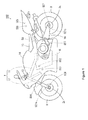
- FIG. 1 is a schematic side view showing the configuration of the motorcycle according to the present embodiment.
- the motorcycle 100 of Figure 1 includes a main body 1.
- the main body 1 includes a body frame 11 and a front fork 12.
- the front fork 12 is attached to the front end of the body frame 11 to be rotatable to the right and left.
- the front fork 12 is telescopable and functions as a front suspension.
- a handle 13 is provided at the upper end of the front fork 12, and a front wheel 2 is attached to the lower end of the front fork 12 to be rotatable.
- a wheel rotation speed sensor SE1a and a stroke sensor SE4 are attached to the front fork 12.
- the wheel rotation speed sensor SE1 a detects a rotation speed of the front wheel 2.
- a moving speed (a vehicle speed) of the main body 1 is acquired from a result of the detection of the wheel rotation speed sensor SE1 a.
- the stroke sensor SE4 detects an amount of extension and contraction of the front fork 12 as an amount of stroke of the front suspension.
- An engine 5 is arranged at substantially the center of the body frame 11.
- An engine rotation speed sensor SE2 for detecting a rotation speed of the engine 5 is provided at the engine 5.
- a throttle opening sensor SE3 is provided at a throttle valve 5a (see below-mentioned Figure 3 ) that controls an amount of intake of the engine 5.
- the throttle opening sensor SE3 detects an opening of the throttle valve 5a (a degree of throttle opening).
- a swing arm 16 and a stroke sensor SE5 are provided behind the engine 5.
- the swing arm 16 is swingable with respect to the body frame 11 and functions as a rear suspension.
- a rear wheel 3 is attached to the rear end of the swing arm 16 to be rotatable.
- a torque (rotational force) generated by the engine 5 is transmitted to the rear wheel 3, so that the rear wheel 3 is driven.
- the stroke sensor SE5 detects an amount of swing of the swing arm 16 as an amount of stroke of the rear suspension.
- a wheel rotation speed sensor SE1 b is provided at the swing arm 16.
- the wheel rotation speed sensor SE1 b detects a rotation speed of the rear wheel 3.
- a reduction gear ratio by a transmission (not shown) is acquired from a result of the detection of each of the engine rotation speed sensor SE2 and the wheel rotation speed sensor SE1 b. Further, the vehicle speed may be acquired from the result of the detection of the wheel rotation speed sensor SE1 b.
- a brake 2a is provided at the front wheel 2, and a brake 3a is provided at the rear wheel 3.
- a brake lever 44 ( Figure 2 ), described below, is operated, the front wheel 2 is braked by the brake 2a. Further, when a footbrake (not shown) is operated, the rear wheel 3 is braked by the brake 3a.
- a brake sensor SE6 is provided at the brake 2a, and a brake sensor SE7 is provided at the brake 3a.
- the brake sensor SE6 detects the braking force of the front wheel 2 by the brake 2a, and the brake sensor SE7 detects the braking force of the rear wheel 3 by the brake 3a.
- each of the brake sensors SE6, SE7 detects the braking force based on oil pressure for driving each of the brakes 2a, 3a.
- the braking force of each of the front wheel 2 and the rear wheel 3 may be detected based on a control value of each of the brakes 2a, 3a by the antilock brake system instead of the use of the brake sensors SE6, SE7.
- a sensor that detects an amount of operation of each of the brake lever 44 and the footbrake may be provided, and the braking force of each of the front wheel 2 and the rear wheel 3 may be detected based on a result of the detection of each of these sensors.
- a fuel tank 14 is provided above the engine 5, and a seat 15 is provided behind the fuel tank 14.
- An ECU (Electronic Control Unit) 50, an acceleration sensor SE8 and a tilt angle sensor SE9 are provided above the rear wheel 3.
- a plane including the center of the body frame 11 in a width direction, the center of the front wheel 2 in the width direction and the center of the rear wheel 3 in the width direction is referred to as a vehicle center surface.
- a direction parallel to the vehicle center surface and a horizontal plane is defined as a front-to-rear direction
- a direction perpendicular to the horizontal plane is defined as an up-and-down direction
- a direction perpendicular to the vehicle center surface is defined as a transverse direction.
- the acceleration sensor SE8 detects acceleration of the main body 1.
- the tilt angle sensor SE9 is a gyro sensor, for example, and detects a tilt angle of the motorcycle 100.
- the tilt angle of the motorcycle 100 means an angle formed by the vehicle center surface with respect to a vertical direction
- a bank angle of the motorcycle 100 means an angle formed by the vehicle center surface with respect to a direction perpendicular to a road surface. When the road surface is horizontal, the bank angle of the motorcycle 100 coincides with the tilt angle of the motorcycle 100.
- FIG. 2 is a schematic top view showing the handle 13 of the motorcycle 100 and its peripheral portions.
- a fixed grip 41 is provided at a left portion of the handle 13, and an accelerator grip 42 is provided at a right portion of the handle 13.
- the accelerator grip 42 is provided to be rotatable in a predetermined range of a rotation angle.
- the throttle opening is adjusted by the operation of the accelerator grip 42.
- the driving force of the engine 5 of Figure 1 is adjusted.
- a clutch lever 43 for disengaging a clutch (not shown) is provided in front of the fixed grip 41.
- the brake lever 44 for operating the brake 2a of Figure 1 is provided in front of the accelerator grip 42.
- a starter switch 45 for starting the engine 5 of Figure 1 is provided to be adjacent to the accelerator grip 42.
- a display 46 is provided at the center of the handle 13.
- the display 46 displays various information regarding the travel of the motorcycle 100.
- the display 46 displays the vehicle speed and the rotation speed of the engine 5.
- the display 46 may display information regarding a rider and a loaded object (hereinafter referred to as load information), and/or information for assisting and supporting the driving (hereinafter referred to as auxiliary information) may be displayed.
- load information a rider and a loaded object
- auxiliary information information for assisting and supporting the driving
- the display 46 may be configured such that various information can be entered by a driver.
- the display 46 is constituted by a touch panel, for example.
- FIG 3 is a block diagram showing the configuration of the control system of the motorcycle 100.
- the ECU 50 includes a CPU (Central Processing Unit) 51, a ROM (Read Only Memory) 52 and a RAM (Random Access Memory) 53.
- the ROM 52 stores a control program of the CPU 51 and the like. Further, the ROM 52 stores various fixed values of the motorcycle 100 as vehicle information.
- the RAM 53 stores various data and functions as a processing area of the CPU 51.
- the CPU 51 performs a wheel force adjustment process, described below, by executing the control program stored in the ROM 52. In this case, the CPU 51 realizes the function of each of a wheel force calculator 61, a wheel force corrector 62 and a travel controller 63.
- the CPU 51 is an example of a wheel force acquisition device.
- the results of the detections made by each of the wheel rotation speed sensors SE1 a, SE1 b, the engine rotation speed sensor SE2, the throttle opening sensor SE3, the stroke sensors SE4, SE5, the brake sensors SE6, SE7, the acceleration sensor SE8 and the tilt angle sensor SE9 are supplied to the CPU 51.
- the CPU 51 calculates wheel force (tyre force) exerted between the front wheel 2 and the road surface, and between the rear wheel 3 and the road surface based on the result of the detection of each of these. Further, the CPU 51 controls the engine 5, the throttle valve 5a and the brakes 2a, 3a based on the calculated wheel force. Thus, the travel of the motorcycle 100 is controlled.
- the motorcycle 100 travels with one or more additional object or objects or load including at least the rider.
- the rider includes at least the driver, and may further include a passenger.
- the load may include the loaded object in addition to the rider.
- the load may be used herein to include any additional object or objects, body, person or the like that is carried by the motorcycle.
- a combination or entirety of the motorcycle 100 and the load is referred to as a movable body 100A.
- the wheel force includes longitudinal force, transverse force and up-and-down force.
- the longitudinal force is exerted in a direction parallel to the moving direction of the motorcycle 100 and parallel to the road surface.
- the transverse force is exerted in a direction perpendicular to the moving direction of the motorcycle 100 and parallel to the road surface.
- the up-and-down force is exerted in a direction perpendicular to the road surface.
- the load is the driver 200.
- the condition of the load includes mass, posture and the number of riders, mass of the loaded object and the like.
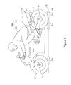
- Figure 4 is a diagram for explaining the longitudinal force of the front wheel 2 and the rear wheel 3.
- the driving force is generated by the engine 5 ( Figure 1 ), and when the driving force is transmitted to the rear wheel 3, driving force Frt in a forward direction is exerted on the rear wheel 3 as shown in Figure 4 .
- the driving force Frt can be calculated based on the rotation speed of the engine 5 ( Figure 1 ) detected by the engine rotation speed sensor SE2 ( Figure 1 ), the throttle opening detected by the throttle opening sensor SE3 ( Figure 1 ) and the rotation speed of the rear wheel 3 detected by the wheel rotation speed sensor SE1 b.
- the brake force Ff1 is detected by the brake sensor SE6 ( Figure 3 ).
- the braking force Fr1 is detected by the brake sensor SE7 ( Figure 3 ).
- the braking force Frb can be calculated based on the rotation speed of the engine 5 detected by the engine rotation speed sensor SE2 ( Figure 3 ), the throttle opening detected by the throttle opening sensor SE3 ( Figure 3 ), and the rotation speed of the rear wheel 3 detected by the wheel rotation speed sensor SE1 b.
- the braking force Ff1 is equivalent to the longitudinal force of the front wheel 2. Further, a resultant or net force resulting from the driving force Frt and the braking force Fr1, Frb is equivalent to the longitudinal force of the rear wheel 3. The resultant or net force resulting from the longitudinal force of the front wheel 2 and the rear wheel 3 is equivalent to force Ffr exerted on the movable body 100A in the front-to-rear direction.
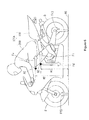
- Figure 5 is a diagram for explaining the transverse force and the up-and-down force of each of the front wheel 2 and the rear wheel 3.
- Figure 6 is a diagram for explaining a load movement.
- the motorcycle 100 tilts in a leftward direction or in a rightward direction with respect to the vertical direction.
- centrifugal force Fc in an outward direction is exerted on the movable body 100A.
- gravity Fg is exerted on the movable body 100A. It can be considered that the force of gravity Fg and the centrifugal force Fc are typically exerted on a center of gravity GC of the movable body 100A.
- a resultant or net force Fh resulting from the centrifugal force Fc and the force of gravity Fg is exerted in a direction perpendicular to the front-to-rear direction (hereinafter referred to as an axis direction) on a plane PL including a ground contact point of each of the front wheel 2 and the rear wheel 3, and the center of gravity GC of the movable body 100A.
- an angle formed by the plane PL with respect to a direction AD perpendicular to the road surface RS is referred to as a bank angle ⁇ a of the movable body 100A.
- Transverse force Ff2 and up-and-down force Ff3 are exerted on the front wheel 2 from the road surface RS, and transverse force Fr2 and up-and-down force Fr3 are exerted on the rear wheel 3 from the road surface RS, to balance with the resultant or net force Fh.
- the transverse forces Ff2 and Fr2 are exerted on the front wheel 2 and the rear wheel 3 respectively in an inward direction (a direction nearer to the center of turn) from the road surface RS, and the up-and-down forces Ff3 and Fr3 are exerted on the front wheel 2 and the rear wheel 3 respectively in a perpendicular direction from the road surface RS.
- a resultant or net force Ff4 resulting from the transverse force Ff2 and the up-and-down force Ff3, and a resultant or net force Fr4 resulting from the transverse force Fr2 and the up-and-down force Fr3 are respectively exerted in, or collinear with, the axis direction.
- the resultant or net forces Ff4 and Fr4 are referred to as axis direction forces Ff4 and Fr4, respectively.
- the sum of the axis direction forces Ff4 and Fr4 is equal to the resultant or net force Fh.
- a relation between the axis direction force Ff4 and the transverse force Ff2 is expressed in the following formula (1a), and a relation between the axis direction force Ff4 and the up-and-down force Ff3 is expressed in the following formula (1b).
- a relation between the axis direction force Fr4 and the transverse force Fr2 is expressed in the following formula (2a), and a relation between the axis direction force Fr4 and the up-and-down force Fr3 is expressed in the following formula (2b).
- Ff ⁇ 2 Ff ⁇ 4 ⁇ sin ⁇ a
- Ff ⁇ 3 Ff ⁇ 4 ⁇ cos ⁇ a
- Ff ⁇ 2 Ff ⁇ 4 ⁇ sin ⁇ a
- Fr ⁇ 3 Ff ⁇ 4 ⁇ cos ⁇ a
- Each of the transverse forces Ff2 and Fr2 differ depending on the bank angle ⁇ a of the movable body 100A, and each of the up-and-down forces Ff3 and Fr3 differ depending on the force due to gravity Fg.
- the sum of the up-and-down forces Ff3 and Fr3 is equal to the force of gravity Fg.
- the mass of the motorcycle 100 is substantially constant, and is stored in advance as the vehicle information.
- the mass of the load is not constant. Therefore, the force due to gravity Fg differs depending on the mass of the load, so that the sum of the up-and-down forces Ff3 and Fr3 differs.
- a ratio of the axis direction forces Ff4 to Fr4 differs depending on the position of the center of gravity GC of the movable body 100A in the front-to-rear direction (hereinafter referred to as a front-to-rear position), for example. Further, the ratio of the axis direction forces Ff4 to Fr4 differs depending on the load movement generated by inertial force and air resistance.
- inertial force Fi in the rearward direction is generated at the movable body 100A at the time of the acceleration of the motorcycle 100
- the inertial force Fi in the forward direction is generated at the movable body 100A at the time of the deceleration of the motorcycle 100.
- the inertial force Fi in the rearward direction is expressed in a positive value
- the inertial force Fi in the forward direction is expressed in a negative value. It can be considered that the inertial force Fi is typically exerted on the center of gravity GC of the movable body 100A.
- 'm' is the mass of the movable body 100A
- 'a' is the acceleration of the motorcycle 100. Therefore, the mass of the movable body 100A differs depending on the mass of the load, so that the inertial force Fi differs.
- the air resistance Fa in the rearward direction is exerted on the travelling movable body 100A. It can be considered that the air resistance Fa is typically exerted on the center of aerodynamic force AC of the movable body 100A.
- 'p' is air density
- 'Cd' is a drag coefficient of the movable body 100A
- 'A' is a frontal projected area of the movable body 100A
- 'v' is the vehicle speed.
- the vehicle speed v is acquired from the result of the detection of the wheel rotation speed sensor SE1a.
- a multiplication value CdA of the drag coefficient and the frontal projected area (hereinafter referred to as a drag calculation value CdA) differs depending on the condition of the load. For example, the larger a tilt angle of the upper half of the body of the driver 200 is, the smaller the drag calculation value CdA is. Therefore, the air resistance Fa differs depending on the condition of the load.
- the load movement is generated between the front wheel 2 and the rear wheel 3 by the inertial force Fi and the air resistance Fa.
- An amount of load movement W1 generated by the inertial force Fi is expressed in the following formula (5).
- An amount of load movement W2 generated by the air resistance Fa is expressed in the following formula (6).
- W ⁇ 1 Fi x H ⁇ 1 / L
- W ⁇ 2 Fa x H ⁇ 2 / L
- the amounts of load movement W1, W2 respectively indicate the movement amounts of the load from the front wheel 2 to the rear wheel 3.
- the amount of load movement W1 is a positive value at the time of the acceleration, and is a negative value at the time of the deceleration.
- the amount of load movement W2 is a positive value at the time of both the acceleration and deceleration.
- 'H1' is a height of the center of gravity GC of the movable body 100A
- 'H2' is a height of the center of aerodynamic force AC of the movable body 100A
- 'L' is a wheelbase of the motorcycle 100 (a distance between the rotational center of the front wheel 2 and the rotational center of the rear wheel 3).
- the height H1 of the center of gravity GC and the height H2 of the center of aerodynamic force AC are the distance from the road surface RS to the center of gravity GC in the axis direction, and the distance from the road surface RS to the center of aerodynamic force AC, respectively.
- the wheelbase L is a fixed value of the motorcycle 100, and is stored in advance as the vehicle information.
- the sum of the amounts of load movement W1 and W2 is the amount of change of the axis direction force Ff4, Fr4.
- Ff4s, Fr4s the actual axis direction forces Ff4 and Fr4 are respectively expressed in the following formulas (7) and (8).
- Ff ⁇ 4 Ff ⁇ 4 ⁇ s / cos ⁇ a - W ⁇ 1 + W ⁇ 2
- Ff ⁇ 4 Ff ⁇ 4 ⁇ s / cos ⁇ a + W ⁇ 1 + W ⁇ 2
- each of the height H1 of the center of gravity GC of the formula (5), the height H2 of the center of aerodynamic force AC of the formula (6) and the bank angle ⁇ a differs depending on the condition of the load. Further, each of the axis direction forces Ff4s and Fr4s of each of the formulas (7) and (8) differ depending on the mass of the load and the position of the center of gravity GC.
- each of the front-to-rear position and the height H1 of the center of gravity GC, the bank angle ⁇ a, the mass, the drag calculation value CdA and the height H2 of the center of aerodynamic force AC, of the movable body 100A is estimated based on the condition of the load.
- Each of the transverse forces Ff2 and Fr2 and the up-and-down forces Ff3 and Fr3 are determined based on their estimated value.
- the vehicle is sufficiently large compared to the load such as the rider and the loaded object, and the load is basically located in the vehicle. Further, stability of the vehicle itself is high, and the vehicle hardly tilts with respect to the road surface. Therefore, the change in the wheel force due to the condition of load is small, and it is hardly necessary to consider the condition of the load in calculating the wheel force.
- various parameters that are necessary for the calculation of the transverse forces Ff2 and Fr2 and the up-and-down forces Ff3 and Fr3 are estimated based on the condition of the load.
- the transverse forces Ff2 and Fr2 and the up-and-down forces Ff3 and Fr3 that are calculated are corrected based on the condition of the load.
- the transverse forces Ff2 and Fr2 and the up-and-down forces Ff3 and Fr3 that correspond to the condition of the load are acquired.
- the force Ffr ( Figure 4 ) exerted on the movable body 100A in the front-to-rear direction can be calculated from the longitudinal force of each of the front wheel 2 and the rear wheel 3.
- the force Ffr is expressed in the following formula (9) as an equation of motion.
- Ffr ma
- 'm' is the mass of the movable body 100A
- 'a' is the acceleration of the motorcycle 100. Therefore, the calculated force Ffr is divided by the acceleration 'a' detected by the acceleration sensor SE8, whereby the mass 'm' of the movable body 100A is found. Further, the mass of the motorcycle 100 stored as the vehicle information is subtracted from the found mass 'm' of the movable body 100A, whereby the mass of the load is estimated.
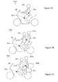
- FIGs 7A to 7C are diagrams for explaining a relation between the mass of the load and the center of gravity position.
- each of black dots GCa indicates the center of gravity of the motorcycle 100
- each of black dots GCb indicates a center of gravity of the load.
- a position of the center of gravity GCa of the motorcycle 100 does not differ depending on the condition of the load but is constant.
- the center of gravity GCb of the load differs depending on the condition of the load.
- the load only includes the driver 200.
- the load includes the passenger 200a in addition to the driver 200.
- the passenger 200a is seated behind the driver 200, and a center of gravity of the passenger 200a is in a higher position than a center of gravity of the driver 200.
- the center of gravity GCb of the load shifts in the rearward direction and is located high relative to that of the example of Figure 7A .
- the load includes the loaded object 200b in addition to the driver 200 and the passenger 200a.
- the loaded object 200b is loaded behind the passenger 200a.
- a center of gravity of the loaded object 200b is lower than the center of gravity of the passenger 200a.
- the center of gravity GCb of the load shifts in the rearward direction and is in a lower position relative to that of the example of Figure 7B .
- each of the front-to-rear position of the center of gravity GCb and the height of the center of gravity GCb is estimated based on the mass of the load.
- information of the center of gravity position showing the relation between the mass of the load and the position of the center of gravity GCb is stored in advance in the ROM 52 of Figure 3 .
- the position of the center of gravity GCb of the load is estimated based on the mass of the load calculated from the information of the center of gravity position and the above formula (9).
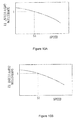
- Figures 8A and 8B are diagrams showing the examples of the information of the center of gravity position.
- the abscissa indicates the mass of the load
- the ordinate indicates the front-to-rear position of the center of gravity GCb.
- the front-to-rear position is expressed as the distance between the front end of the movable body 100A and the center of gravity GCb in the front-to-rear direction, for example.
- the abscissa indicates the mass of the load
- the ordinate indicates the height of the center of gravity GCb.
- the loaded object 200b is loaded only when the passenger 200a is riding, and the loaded object 200b is not loaded when the passenger 200a is not riding.
- the passenger 200a and the loaded object 200b are sequentially added to the load, so that the mass of the load gradually increases, and the center of gravity GCb gradually shifts in the rearward direction. Therefore, in the example of Figure 8A , an amount of shift of the center of gravity GCb in the rearward direction increases as the mass of the load increases. Further, when the passenger 200a is added to the load, the center of gravity Gb is raised. On the other hand, when the loaded object 200b is further added to the load, the center of gravity Gb is lowered compared to the case in which only the passenger 200a is added.
- the center of gravity GCb is raised as the mass of the load increases.
- the center of gravity GCb is lowered as the mass of the load increases.
- the threshold value TH1 is equivalent to the standard mass acquired when the load is the driver 200 and the passenger 200a.
- the front-to-rear position and the height of the center of gravity GCb of the load are estimated.
- the mass and the position of the center of gravity GCa of the motorcycle 100 are stored in advance as the vehicle information.
- the position of the center of gravity GCa is determined relative to a constant standard position (the rotational center of the front wheel 2 or the rear wheel 3, for example).
- the position of the center of gravity GC of the movable body 100A is estimated based on the mass and the position of the center of gravity GCb of the load that are estimated, and the mass and the position of the center of gravity GCa of the motorcycle 100 that are stored as the vehicle information.
- the tilt angle of the upper half of the body of the driver 200 changes depending on the travel condition of the movable body 100A.
- the tilt angle of the upper half of the body of the driver 200 with respect to the direction perpendicular to the road surface is referred to as an upper body angle.
- Figure 9A to 9C are diagrams for explaining the upper body angle of the driver 200.
- the upper body angle ⁇ b of the driver 200 in the example of Figure 9A is larger than the upper body angle ⁇ b of the driver 200 in the example of Figure 9B
- the upper body angle ⁇ b of the driver 200 in the example of Figure 9B is larger than the upper body angle ⁇ b of the driver 200 in the example of Figure 9C
- the lower the speed of the movable body 100A is, the smaller the upper body angle ⁇ b of the driver 200 is likely to be, as shown in the example of Figure 9C .
- Each of the drag calculation value CdA and the height H2 of the center of aerodynamic force AC differs depending on the upper body angle ⁇ b of the driver 200. Specifically, the larger the upper body angle ⁇ b is, the smaller the drag calculation value CdA of the above formula (4) is and the lower the center of aerodynamic force AC is. Therefore, the higher the vehicle speed is, the smaller the drag calculation value CdA is likely to be and the lower the center of aerodynamic force AC is likely to be.
- each of the drag calculation value CdA and the height H2 of the center of aerodynamic force AC is estimated based on the result of the detection of the wheel rotation speed sensor SE1 a.
- standard values of the drag calculation value CdA and the height H2 of the center of aerodynamic force AC are determined in advance, respectively.
- the drag calculation value CdA and the height H2 of the center of aerodynamic force AC of the movable body 100A acquired when the upper body angle ⁇ b of the driver 200 is a constant value are set to the standard values, respectively.
- the set standard values are stored in the ROM 52 of Figure 3 , for example.
- the standard value of the drag calculation value CdA is multiplied by a correction coefficient T1 corresponding to the result of the detection of the wheel rotation speed sensor SE1a. Further, the standard value of the height H2 of the center of aerodynamic force AC is multiplied by a correction coefficient T2 corresponding to the result of the detection of the wheel rotation speed sensor SE1a.
- Figures 10A and 10B are diagrams showing a relation between the vehicle speed and the correction coefficient T1, and a relation between the vehicle speed and the correlation coefficient T2.
- the abscissa indicates the vehicle speed
- the ordinate indicates the correction coefficient T1 or the correction coefficient T2 respectively.
- the correction coefficient T1 is set such that the higher the vehicle speed is, the smaller the correction coefficient T1 is.
- the correction coefficient T2 is set such that the higher the vehicle speed is, the smaller the correction coefficient T2 is.
- the correction coefficients T1, T2 are 1, respectively. This means that when the vehicle speed is S1, the drag calculation value CdA and the height H2 of the center of aerodynamic force AC are the standard values, respectively.
- the correction coefficients T1, T2 are larger than 1, respectively, when the vehicle speed is lower than the S1, and the correction coefficients T1, T2 are larger than 0 and less than 1, respectively, when the vehicle speed is higher than S1.
- the drag calculation value CdA and the height H2 of the center of aerodynamic force AC in the example of Figure 9B are set to the standard values, respectively.
- the correction coefficients T1, T2 are 1, respectively, in the example of Figure 9B
- the correction coefficients T1, T2 are larger than 0 and less than 1, respectively, in the example of Figure 9A
- the correction coefficients T1, T2 are larger than 1, respectively, in the example of Figure 9C .
- the predetermined standard value is multiplied by each of the correction coefficients T1, T2 corresponding to the result of the detection of the wheel rotation speed sensor SE1a, whereby the estimated value of each of the drag calculation value CdA and the height H2 of the center of aerodynamic force AC of the movable body 100A is acquired.
- the upper body angle ⁇ b of the driver 200 is likely to be large as in the example of Figure 9A .
- the upper body angle ⁇ b of the driver 200 is likely to be small as in the example of Figure 9C . Therefore, the higher the acceleration is, the smaller the drag calculation value CdA is likely to be and the lower the center of aerodynamic force AC is likely to be.
- each of the drag calculation value CdA and the height H2 of the center of aerodynamic force AC may be estimated based on the result of the detection of the acceleration sensor SE8 instead of the result of the detection of the wheel rotation speed sensor SE1 a.
- the standard values of the drag calculation value CdA and the height H2 of the center of aerodynamic force AC are determined in advance, respectively, and the standard values are multiplied by the correction coefficient corresponding to the result of the detection of the acceleration sensor SE8.
- the estimated values of each of the drag calculation value CdA and the height H2 of the center of aerodynamic force AC of the movable body 100A are acquired.
- each of the drag calculation value CdA and the height H2 of the center of aerodynamic force AC may be estimated based on the result of detection of each of the wheel rotation speed sensor SE1 a and the acceleration sensor SE8. Also in this case, the standard values of the drag calculation value CdA and the height H2 of the center of aerodynamic force AC are determined in advance, respectively, and the standard values are multiplied by the correction coefficients corresponding to the results of the detection of the wheel rotation speed sensor SE1a and the acceleration sensor SE8. Thus, the estimated value of each of the drag calculation value CdA and the height H2 of the center of aerodynamic force AC of the movable body 100A are acquired.
- the drag calculation value CdA is likely to be large, and the center of aerodynamic force AC is likely to be high. Therefore, further correction for the estimated value of each of the drag calculation value CdA and the height H2 of the center of aerodynamic force AC may be performed based on the mass calculated from the above formula (9). Specifically, the estimated value of each of the drag calculation value CdA and the height H2 of the center of aerodynamic force AC is corrected such that the larger the calculated mass is, the larger the drag calculation value CdA is and the higher the center of aerodynamic force AC is.
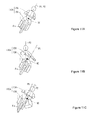
- FIGS 11A to 11C are diagrams for explaining the transverse posture of the driver 200.
- the tilt angle of the motorcycle 100 is the same.
- an axis in the up-and-down direction of the motorcycle 100 is referred to as an up-and-down axis P1
- an axis in the up-and-down direction of the driver 200 is referred to as an up-and-down axis P2.
- the transverse posture of the driver 200 is lean-with, and the up-and-down axis P1 of the motorcycle 100 coincides with the up-and-down axis P2 of the driver 200 as viewed from the front.
- the transverse posture of the driver 200 is likely to be lean-with as in the example of Figure 11A .
- the transverse posture of the driver 200 is lean-out, and the up-and-down axis P2 of the driver 200 is positioned outside of the up-and-down axis P1 of the motorcycle 100 (a position that is further away from the center of turn than the up-and-down axis P1) as viewed from the front.
- the position of the center of gravity GC of the movable body 100A shifts in the outward direction (the direction away from the center of turn) and is raised as compared to the example of Figure 11A . Therefore, the tilt angle of the movable body 100A decreases as compared to the example of Figure 11A .
- the transverse posture of the driver 200 is likely to be lean-out as in the example of Figure 11B .
- the transverse posture of the driver 200 is lean-in
- the up-and-down axis P2 of the driver 200 is positioned inside of the up-and-down axis P1 of the motorcycle 100 (a position that is nearer to the center of turn than the up-and-down axis P1) as viewed from the front.
- the position of the center of gravity GC of the movable body 100A shifts in the inward direction (a direction nearer to the center of turn) and is lowered as compared to the example of Figure 11A .
- the transverse posture of the driver 200 is likely to be lean-in as in the example of Figure 11C .
- each of the height H1 of the center of gravity GC and the bank angle ⁇ a is estimated based on the result of the detection of each of the stroke sensors SE4, SE5, the acceleration sensor SE8 and the tilt angle sensor SE9.
- each of the height H1 of the center of gravity GC and the bank angle ⁇ a, acquired when the transverse posture of the driver 200 is assumed to be lean-with (see Figure 11A ) and the road surface is assumed to be horizontal, is calculated as the standard value.
- the tilt angle of the motorcycle 100 coincides with the bank angle of the motorcycle 100
- the bank angle of the motorcycle 100 substantially coincides with the bank angle ⁇ a of the movable body 100. Therefore, the tilt angle detected by the tilt angle sensor SE9 is considered as the standard value of the bank angle ⁇ a of the movable body 100A.
- the height H1 of the center of gravity GC (see Figures 8B ) of the movable body 100A that is estimated based on the mass of the load is set to the standard value.
- the vibration of the front wheel 2 and the rear wheel 3 is large as compared to the case in which the movable body 100A travels on the general paved road and the paved road for races. Therefore, the change in the amount of stroke of the front suspension and the rear suspension increases. Further, when the movable body 100A travels on the paved road for races, changes in the acceleration of the motorcycle 100 increase as compared to the case in which the movable body 100A travels on the general paved road.
- the calculated standard value of each of the height H1 of the center of gravity GC and the bank angle ⁇ a is corrected based on the result of the detection of each of the stroke sensors SE4, SE5 and the acceleration sensor SE8.
- a constant correction value A1 is added to the standard value of the height H1 of the center of gravity GC. Further, a constant correction value B1 is subtracted from the standard value of the bank angle ⁇ a.
- the road surface is likely to be the general paved road. Therefore, it can be estimated that the transverse posture of the driver 200 is lean-with. In this case, the correction of the standard value of each of the height H1 of the center of gravity GC and the bank angle ⁇ a is not performed.
- each of the height H1 of the center of gravity GC and the bank angle ⁇ a is estimated based on the transverse posture of the driver 200.
- the estimated bank angle ⁇ a may be corrected based on the tilt angle of the road surface (hereinafter referred to as the cant angle).
- the cant angle When the movable body 100A travels on the general paved road, a constant correlation is generated between the tilt angle of the motorcycle 100 and the tilt angle of the road surface (a cant angle).
- Figure 12 is a diagram showing a relation between the tilt angle of the motorcycle 100 and the cant angle of the road surface.
- the abscissa indicates the travel position of the motorcycle 100
- the ordinate indicates the tilt angle of the motorcycle 100 and the cant angle of the road surface.
- the larger the cant angle of the road surface is, the larger the tilt angle of the motorcycle 100 tends to be.
- the cant angle of the road surface is estimated based on the tilt angle detected by the tilt angle sensor SE9.
- cant angle information showing the relation between the tilt angle of the motorcycle 100 and the cant angle of the road surface is stored in advance in the ROM 52 of Figure 3 .
- the cant angle of the road surface is estimated based on the tilt angle detected by the tilt angle sensor SE9 and the stored cant angle information.
- the bank angle ⁇ a is corrected based on the estimated cant angle. Specifically, the bank angle ⁇ a is corrected to be decreased by an angle equivalent to the estimated cant angle.
- the bank angle ⁇ a corresponding to the cant angle of the road surface is acquired.
- the cant angle of the road surface may be acquired using a GPS (Global Positioning System).
- GPS Global Positioning System
- the cant angle of each of the general roads in various areas is stored in advance as cant angle position information.
- the cant angle of the road surface on which the motorcycle 100 is travelling can be acquired based on a present position of the motorcycle 100 acquired by the GPS and the stored cant angle position information.
- the bank angle ⁇ a, the front-to-rear position and the height H1 of the center of gravity GC, the mass of the movable body 100A, the drag calculation value CdA and the height H2 of the center of aerodynamic force AC are estimated based on the condition of the load.
- the inertial force Fi exerted on the movable body 100A is calculated by the above formula (3) using the estimated mass.
- the value detected by the acceleration sensor SE8 is used as the acceleration 'a' of the formula (3).
- the air resistance Fa ( Figure 6 ) exerted on the movable body 100A is calculated by the above formula (4) using the estimated drag calculation value CdA.
- a predetermined constant value may be used, or a value conveniently calculated by the detection of a temperature, air pressure and the like may be used, as the air density ⁇ of the formula (4).
- the value acquired from the result of the detection of the wheel rotation speed sensor SE1a is used as the vehicle speed v of the formula (4).
- Each of the amounts of load movement W1 and W2 are respectively calculated by the above formulas (5) and (6) respectively using the inertial force Fi and the air resistance Fa that are calculated, and the height H1 of the center of gravity GC and the height H2 of the center of aerodynamic force AC that are estimated.
- a value stored as the vehicle information is used as the wheelbase L of the formulas (5) and (6).
- the axis direction forces Ff4 and Fr4 are respectively calculated by the above formulas (7) and (8) respectively using the calculated amounts of load movement W1, W2 and the estimated bank angle ⁇ a.
- Each of the axis direction forces Ff4s and Fr4s of each of the formulas (7) and (8) can be calculated based on the estimated front-to-rear position of the center of gravity GC and mass of the movable body 100A.
- Each of the transverse forces Ff2 and Fr2 and the up-and-down forces Ff3 and Fr3 are found from the calculated axis direction forces Ff4s and Fr4s and the estimated bank angle ⁇ a.
- the travel control of the motorcycle 100 is performed based on the calculated wheel force.
- the travel control of the motorcycle 100 using a friction circle will be described as a specific example.
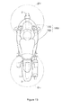
- Figure 13 is a diagram showing the friction circle corresponding to each of the front wheel 2 and the rear wheel 3 of the motorcycle 100.
- a limit value of a grip of the front wheel 2 is shown as a friction circle CFf
- a limit value of a grip of the rear wheel 3 is shown as a friction circle CFr.
- the shape of the friction circles CFf, CFr is not limited to a perfect circle as in the example of Figure 13 , but may be in another shape such as an ellipse.
- the size of the friction circle CFf (a diameter in the present example) is set based on the calculated up-and-down force Ff3 of the front wheel 2, and the size of the friction circle CFr is set based on the calculated up-and-down force Fr3 of the rear wheel 3.
- the set friction circle CFf and the calculated transverse force and longitudinal force of the front wheel 2 are compared. Further, the set friction circle CFr and the calculated transverse force and longitudinal force of the rear wheel 3 are compared.
- the sizes of the respective friction circles CFf and CFr are equivalent to the respective up-and-down force Ff3, Fr3 multiplied by the friction coefficients between the front wheel 2 and the road surface, and between the rear wheel 3 and the road surface, respectively. Therefore, for example, at the time of the slip of the rear wheel 3, each of the driving force and the transverse force exerted on the rear wheel 3 is detected, and the friction coefficient may be estimated based on the result of this detection. In this case, the size of each of the friction circles CFf, CFr can be set using the estimated friction coefficient. Thus, each of the friction circles CFf, CFr can be appropriately set according to the condition of the road surface.
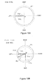
- Figures 14A and 14B are diagrams for explaining a relation between each of the friction circles CFf, CFr and the wheel force.
- an origin point OP is set at the center of each of the friction circles CFf, CFr.
- One direction of the longitudinal axis indicates the magnitude of the longitudinal force in the forward direction (the driving force)
- another direction of the longitudinal axis indicates the magnitude of the longitudinal force in the rearward direction (the braking force)
- the origin point OP being used as a basis.
- one direction of the transverse axis indicates the transverse force in the rightward direction
- another direction of the transverse axis indicates the transverse force in the leftward direction.
- the resultant or net force resulting from the longitudinal force and the transverse force sometimes exceeds the range indicated by the friction circle due to the change in the transverse force.
- the transverse force Fr2a exerted on the rear wheel 3 changes to transverse force Fr2d
- resultant or net force Frd resulting from the transverse force Fr2d and the driving force Frta is exerted on the rear wheel 3.
- the resultant or net force FRd exceeds the range indicated by the friction circle CFr. In this case, the grip of the rear wheel 3 may not be maintained, and the rear wheel 3 may slip.
- Figures 15A and 15B are diagrams showing the changes of the friction circles CFf, CFr at the time of the acceleration of the motorcycle 100.
- Figures 16A and 16B are diagrams showing the changes of the friction circles CFf, CFr at the time of the deceleration of the motorcycle 100.
- transverse forces Ff2b and Fr2b in the leftward direction are exerted on the front wheel 2 and the rear wheel 3 respectively, and driving force Frtb is exerted on the rear wheel 3 as the longitudinal force.
- a resultant or net force FRb resulting from the transverse force Ff2b and driving force Frtb is exerted on the rear wheel 3.
- the resultant or net force FRb exerted on the rear wheel 3 exceeds the range indicated by the friction force CFr. Therefore, the grip of the rear wheel 3 with respect to the road surface is not maintained, and the rear wheel 3 may slip.
- each of transverse force Ff2c, Fr2c in the leftward direction is exerted on each of the front wheel 2 and the rear wheel 3, and braking force Fr1 c is exerted on the rear wheel 3 as the longitudinal force.
- a resultant or net force FRc resulting from the transverse force Ff2c and the braking force Fr1c is exerted on the rear wheel 3.
- the resultant or net force FRc exerted on the rear wheel 3 exceeds the range indicated by the friction circle CFr. Therefore, the grip of the rear wheel 3 with respect to the road surface is not maintained, and the rear wheel 3 may slip.
- the driving force or the braking force that is exerted on the rear wheel 3 is adjusted such that the resultant or net force resulting from the longitudinal force and the transverse force is in the range indicated by the friction circle as for each of the front wheel 2 and the rear wheel 3.
- the adjustment of the driving force is performed by the control of the throttle opening, the ignition timing in the engine 5 and the amount of fuel injection.
- the adjustment of the braking force is performed by the control of the brake 3a or the engine brake.
- Figures 17A and 17B are diagrams for explaining the adjustment of the driving force at the time of the acceleration of the motorcycle 100.
- the driving force Frtb exerted on the rear wheel 3 is decreased to Frtb' as compared to the examples of Figures 15A and 15B .
- the inertial force Fi in the rearward direction exerted on the motorcycle 100 decreases.
- the up-and-down force Ff3 of the front wheel 2 increases, and the up-and-down force Fr3 of the rear wheel 3 decreases.
- the size of the friction circle CFf increases and the size of the friction circle CFr decreases as compared to the examples of the Figures 15A and 15B . Further, the transverse force Ff2b exerted on the front wheel 2 is increased to Ff2b', and the transverse force Fr2b exerted on the rear wheel 3 is decreased to Fr2b'.
- Figures 18A and 18B are diagrams for explaining the adjustment of the driving force at the time of the deceleration of the motorcycle 100.
- the braking force Fr1 c exerted on the rear wheel 3 is decreased to Fr1 c' as compared to the examples of Figures 16A and 16B .
- the inertial force Fi in the forward direction exerted on the motorcycle 100 decreases.
- the up-and-down force Ff3 of the front wheel 2 decreases
- the up-and-down force Fr3 of the rear wheel 3 increases.
- the size of the friction circle CFf decreases, and the size of the friction circle CFr increases, as compared to the examples of Figures 16A and 16B . Further, the transverse force Ff2c exerted on the front wheel 2 is decreased to Ff2c', and the transverse force Fr2c exerted on the rear wheel 3 is increased to Fr2c'.
- the resultant or net force FRc' of the transverse force Fr2c' and the braking force Fr1c' that are exerted on the rear wheel 3 is in the range indicated by the friction circle CFr.
- the grip of the rear wheel 3 with respect to the road surface is maintained.
- the engine brake may be generated such that the braking force is exerted on the rear wheel 3, or the brake 3a may be controlled such that the braking force is exerted on the rear wheel 3, instead of the adjustment of the driving force of the rear wheel 3.
- the resultant or net force resulting from the driving force and the braking force is the longitudinal force.
- the longitudinal force in the forward direction exerted on the rear wheel 3 can be decreased. Therefore, the resultant or net force resulting from the longitudinal force and the transverse force that are exerted on the rear wheel 3 can be adjusted in the range indicated by the friction circle CFr similarly to the examples of Figures 17A and 17B .
- the throttle valve 5a or the engine 5 may be controlled such that the driving force is exerted on the rear wheel 3, instead of the adjustment of the braking force of the rear wheel 3.
- the resultant or net force resulting from the driving force and the braking force is the longitudinal force.
- the longitudinal force in the rearward direction exerted on the rear wheel 3 can be decreased. Therefore, the resultant or net force resulting from the longitudinal force and the transverse force that are exerted on the rear wheel 3 can be adjusted in the range indicated by the friction circle CFr.
- Figure 19 is a flow chart of the wheel force adjustment process performed by the wheel force calculator 61, the wheel force corrector 62 and the travel controller 63, of the CPU 51 of Figure 3 .
- the wheel force adjustment process of Figure 19 is repeatedly performed in a predetermined period.
- the wheel force calculator 61 and the wheel force corrector 62 first calculate the longitudinal force, the transverse force and the up-and-down force as the wheel force of each of the front wheel 2 and the rear wheel 3 based on the result of the detection of each type of the sensors SE1 to SE9, respectively (step S1). In this case, the transverse force and the up-and-down force that are calculated by the wheel force calculator 61 are corrected by the wheel force corrector 62 based on the condition of the load.
- the travel controller 63 sets the friction circles CFf, CFr ( Figure 13 ) based on the calculated up-and-down force of the front wheel 2 and the rear wheel 3 (step S2). Then, the travel controller 63 determines whether or not the calculated resultant or net force resulting from the longitudinal force and the transverse force of the front wheel 2 is in the range of the set friction circle CFf, and determines whether or not the calculated resultant or net force resulting from the longitudinal force and the transverse force of the rear wheel 3 is in the range of the set friction circle CFr (step S3).
- the CPU 51 finishes the wheel force adjustment process.
- the travel controller 63 adjusts the wheel force of the front wheel 2 and the rear wheel 3 such that the resultant or net force is in the range of the corresponding friction circle (step S4).
- the driving force or the braking force of the rear wheel 3 is adjusted.
- the CPU 51 finishes the wheel force adjustment process.
- the condition of the load is estimated based on the result of the detection of each type of sensors SE1 to SE9, and the wheel force of each of the front wheel 2 and the rear wheel 3 is calculated based on the estimated condition of the load.
- the appropriate wheel force corresponding to the mass and the posture of the load and the like is acquired.
- each of the drag calculation value CdA and the height H2 of the center of aerodynamic force AC is estimated based on the posture (the upper body angle) of the driver 200 in the front-to-rear direction, and the air resistance Fa exerted on the movable body 100A is estimated based on the drag calculation value CdA and the height H2 of the center of aerodynamic force AC that are estimated.
- the air resistance Fa can be appropriately found, and the up-and-down force of the front wheel 2 and the rear wheel 3 can be appropriately calculated according to the air resistance Fa.
- the posture of the driver 200 in the front-to-rear direction is estimated based on the result of the detection of the wheel rotation speed sensor SE1 a or the acceleration sensor SE8.
- the posture of the driver 200 in the front-to-rear direction is estimated based on the result of the detection of the wheel rotation speed sensor SE1 a or the acceleration sensor SE8.
- the front-to-rear position and the height H1 of the center of gravity GC of the movable body 100A is estimated based on the mass of the load.
- the driving force transmitted from the engine 5 to the rear wheel 3 is calculated based on the result of the detection by each of the engine rotation speed sensor SE2, the throttle opening sensor SE3 and the wheel rotation speed sensor 1 b, and the mass of the load is estimated based on the calculated driving force and the acceleration detected by the acceleration sensor SE8.
- the mass of the load is estimated based on the calculated driving force and the acceleration detected by the acceleration sensor SE8.
- the height H1 of the center of gravity GC of the movable body 100A is estimated based on the transverse posture of the driver 200, and the transverse force of each of the front wheel 2 and the rear wheel 3 is calculated based on the estimated height H1 of the center of gravity GC.
- the transverse force of each of the front wheel 2 and the rear wheel 3 can be appropriately calculated according to the transverse posture of the driver 200.
- the type of the road surface is estimated based on the result of the detection of each of the stroke sensors SE4, SE5 and the acceleration sensor SE8, and the transverse posture of the driver 200 is estimated based on the estimated type of the road surface.
- the transverse posture of the driver 200 is estimated based on the estimated type of the road surface.
- the friction circle is set based on the calculated up-and-down force, and the travel of the motorcycle 100 is controlled such that the calculated resultant or net force resulting from the longitudinal force and the transverse force does not exceed the range indicated by the friction circle.
- the travel control using the friction circle is performed based on the appropriate longitudinal force, transverse force and up-and-down force that are corresponding to the condition of the load.
- the travel control of the motorcycle 100 is performed based on the calculated vehicle force in the above-mentioned embodiment
- the invention is not limited to this.
- the information for assisting or supporting the driving of the driver 200 (the auxiliary information) may be displayed in the display 46 ( Figure 2 ) based on the calculated wheel force.
- the driving force or the braking force of the rear wheel 3 is not adjusted by the CPU 51, but the driver 200 adjusts the driving force or the braking force of the rear wheel 3 based on the auxiliary information displayed in the display 46.
- a decrease in the driving feeling due to the automatic control is prevented.
- auxiliary information for example, the relation between the friction circle and the wheel force as shown in Figures 14A to 16B may be displayed, or the numerical value indicating the wheel force may be displayed. Alternatively, when the wheel force comes close to a critical value of the range indicated by the friction circle, the alarm indicating that may be displayed. Further, the auxiliary information may be delivered visually or aurally to the driver 200 by sound, vibration or the like.
- the auxiliary information may be transmitted from the motorcycle 100 to an external device by wired or wireless connection.
- the auxiliary information may be transmitted to a mobile apparatus such as a mobile phone or a tablet terminal, and the auxiliary information may be displayed on the screen of its mobile apparatus.
- the auxiliary information may be transmitted from the motorcycle 100 that is travelling on a racecourse to a maintenance facility (a pit) and the like.
- the condition of the load is estimated based on the result of the detection by each type of the sensors SE1 to SE9 in the above-mentioned embodiment, the invention is not limited to this.
- the number, the mass, the posture or the like of the rider may be entered in the ECU 50 as the condition of the load by the operation of the display 46 by the driver 200. In this case, it is possible to easily perform the calculation of the wheel force based on the entered condition of the load.
- the present determination may be performed by another method.
- the road surface is poor, variations are likely to be generated between the rotation speed of the front wheel 2 and the rotation speed of the rear wheel 3.
- the type of the road surface on which the motorcycle 100 is travelling may be acquired using the GPS.
- the type of the road surface on which the motorcycle 100 is travelling may be entered in the ECU 50 by the operation of the display 46 by the driver 200.
- the transverse posture of the driver 200 can be easily estimated based on the type of the road surface that is acquired or entered.
- the mass of the load is estimated by the above formula (9) based on the calculated longitudinal force and the result of the detection by the acceleration sensor SE8, the mass of the load may be estimated by another method.
- the load applied to each of the front wheel 2 and the rear wheel 3 may be calculated based on the result of the detection by each of the stroke sensors SE4, SE5, and the mass of the load may be estimated based on the calculated load and the result of the detection by the acceleration sensor SE8.
- the invention is not limited to this.
- the front wheel 2 may be driven by the engine 5. Further, the wheel force may be calculated only for the wheel that is driven by the engine 5 out of the front wheel 2 and the rear wheel 3, or the wheel force may be calculated for the wheel that is not driven by the engine 5.
- the wheel force calculator is realized by the CPU 51 of the ECU 50 and the control program in the above-mentioned embodiment
- at least part of the functional unit of the wheel force calculator, the wheel force corrector and the movement controller may be realized by the hardware such as an electronic circuit.
- the present invention is not limited to this.
- the present invention may be applied to another saddle-straddling type motor vehicle such as a motor tricycle, an ATV (All Terrain Vehicle) or the like.
- the present invention is not limited to this.
- the present invention may be applied to an electric vehicle including an electric motor as a motor.
- the motorcycle 100 is an example of a saddle-straddling type motor vehicle
- the main body 1 is an example of a main body
- the front wheel 2 or the rear wheel 3 is an example of a wheel
- the engine 5 is an example of a motor
- the wheel force calculator 61 is an example of a wheel force calculator
- the wheel force corrector 62 is an example of a wheel force corrector.
- the acceleration sensor SE8 is an example of an acceleration detector
- the wheel rotation speed sensor SE1 a is an example of a vehicle speed detector
- the display 46 is an example of a posture entry unit and a mass entry unit
- the engine rotation speed sensor SE2 is an example of a posture entry unit and a mass entry unit
- the engine rotation speed sensor SE2 is an example of a posture entry unit and a mass entry unit
- the engine rotation speed sensor SE2 is an example of a posture entry unit and a mass entry unit
- the stroke sensors SE4, SE5 are examples of a load detector and a road surface information acquirer
- the travel controller 63 is an example of a movement controller.
Landscapes
- Engineering & Computer Science (AREA)
- Mechanical Engineering (AREA)
- Transportation (AREA)
- Chemical & Material Sciences (AREA)
- Combustion & Propulsion (AREA)
- Automation & Control Theory (AREA)
- Physics & Mathematics (AREA)
- Mathematical Physics (AREA)
- Control Of Driving Devices And Active Controlling Of Vehicle (AREA)
- Electric Propulsion And Braking For Vehicles (AREA)
- Regulating Braking Force (AREA)
- Control Of Vehicle Engines Or Engines For Specific Uses (AREA)
- General Physics & Mathematics (AREA)
Abstract
Description
- The present invention relates to a saddle-ride or straddle type vehicle, e.g. a saddle-straddling type motor vehicle, a wheel force acquisition device and an associated method of operation.
- There is a technique that controls the travel of a vehicle based on the force exerted between a wheel and a road surface. In a motorcycle described in
WO 2013/014945 A1 , skid motion acceleration is detected based on a vehicle speed, a bank angle, acceleration in a transverse direction and a yaw rate. When the detected skid motion acceleration is greater than or equal to a predetermined threshold value, it is determined that a skid motion is taking place at the wheel. In this case, the driving force or the braking force of the motorcycle is controlled such that the longitudinal force exerted on the wheel decreases. - However, the transverse force and the longitudinal force that generate the skid motion acceleration differ depending on mass, posture and the like of a rider. As such, the transverse force and the longitudinal force cannot be accurately detected by a method described in
WO 2013/014945 A1 . - An object of at least one embodiment of the present invention is to provide a saddle-straddling type motor vehicle and a wheel force acquisition device that can more accurately acquire appropriate wheel force.
- An object of at least one embodiment of the present invention is to obviate or mitigate at least one problem with the prior art.
- Various aspects of the present invention are defined in the independent claims. Some preferred features are defined in the dependent claims.
- An aspect of the present invention is a vehicle, which may comprise a saddle-ride or straddle type vehicle, such as a saddle-straddling type motor vehicle. The vehicle may be configured to carry and/or travel with at least one additional object or objects or a load, which may include at least a rider. The vehicle may comprise a main body, a wheel, a motor for generating driving force, e.g. for moving the main body, a wheel force calculator that calculates wheel force exerted between the wheel and a road surface, and a wheel force corrector that corrects the wheel force calculated by the wheel force calculator based on a condition of the additional object or objects or load.
- The main body may comprise or be configured to be at least partially supported by the wheel, in use.
- In this vehicle, the driving force is generated by the motor, and the main body is moved by the driving force. During the movement of the main body, the wheel force exerted between the wheel and the road surface is calculated by the wheel force calculator. The calculated wheel force is corrected by the wheel force corrector based on the condition of the additional object or objects or load, including at least the rider. Thus, the appropriate wheel force corresponding to the condition of the additional object or objects or load may be acquired.
- The condition of the additional object or objects or load may include posture of the rider in a front-to-rear direction. The wheel force corrector may estimate air resistance, e.g. based on the posture of the rider in the front-to-rear direction. The wheel force corrector may correct the calculated wheel force based on the estimated air resistance.
- The air resistance may differ depending on the posture of the rider in the front-to-rear direction. For example, the larger the tilt angle of the upper half of the body of the rider is, the smaller the air resistance is. The wheel force may differ due to the difference in the air resistance. Therefore, the air resistance may be estimated based on the posture of the rider in the front-to-rear direction, and the wheel force may be corrected based on the estimated air resistance. Thus, the appropriate wheel force corresponding to the posture of the rider in the front-to-rear direction may be acquired.
- The wheel force corrector may estimate a height of a center of aerodynamic force, e.g. based on the posture of the rider in the front-to-rear direction, and may correct the calculated wheel force based on the estimated height of the center of aerodynamic force and/or the estimated air resistance.
- A relation between the air resistance and the wheel force may differ depending on the height of the center of aerodynamic force. Therefore, the height of the center of aerodynamic force may be estimated based on the posture of the rider in the front-to-rear direction, and the wheel force may be corrected based on the estimated height of the center of aerodynamic force and/or the estimated air resistance. Thus, the appropriate wheel force corresponding to the posture of the rider in the front-to-rear direction may be acquired.
- The vehicle may further include an acceleration detector that detects acceleration of the main body. The wheel force corrector may estimate the posture of the rider in the front-to-rear direction, e.g. based on the acceleration detected by the acceleration detector. The wheel force corrector may correct the calculated wheel force based on the estimated posture of the rider in the front-to-rear direction.
- There may be a correlation between the posture of the rider in the front-to-rear direction and the acceleration of the main body. For example, the larger the acceleration of the main body is, the larger the tilt angle of the upper half of the body of the rider is likely to be. Therefore, the posture of the rider in the front-to-rear direction may be estimated based on the acceleration detected by the acceleration detector. Thus, it may be possible to perform the correction of the wheel force based on the posture of the rider in the front-to-rear direction without complicating the configuration.
- The vehicle may further include a vehicle speed detector that detects a speed of the main body. The wheel force corrector may estimate the posture of the rider in the front-to-rear direction, e.g. based on the speed detected by the vehicle speed detector, and may correct the calculated wheel force based on the estimated posture of the rider in the front-to-rear direction.
- There may be a correlation between the posture of the rider in the front-to-rear direction and the speed of the main body. For example, the higher the speed of the main body is, the larger the tilt angle of the upper half of the body of the rider is likely to be. Therefore, the posture of the rider in the front-to-rear direction may be estimated based on the speed detected by the vehicle speed detector. Thus, it may be possible to perform the correction of the wheel force based on the posture of the rider in the front-to-rear direction without complicating the configuration.
- The vehicle may include a posture entry unit in which the posture of the rider in the front-to-rear direction is entered. The wheel force corrector may correct the calculated wheel force based on the posture of the rider in the front-to-rear direction that is entered in the posture entry unit.
- In this case, it may be possible to easily perform the correction of the wheel force based on the posture of the rider in the front-to-rear direction that is entered in the posture entry unit.
- The condition of the additional object or objects or load may include mass of the additional object or objects or load. The wheel force corrector may correct the calculated wheel force based on the mass of the additional object or objects or load.
- The wheel force may differ depending on the mass of the additional object or objects or load. Therefore, the wheel force may be corrected based on the mass of the additional object or objects or load. Thus, the appropriate wheel force corresponding to the mass of the additional object or objects or load may be acquired.
- The wheel force corrector may estimate a position of a center of gravity of a combination, group or entirety, which may include the vehicle and the additional object or objects or load. The wheel force corrector may estimate the position of the center of gravity of the combination, group or entirety based on the mass of the additional object or objects or load. The wheel force corrector may correct the calculated wheel force based on the estimated position of the center of gravity.
- There may be a constant correlation between the mass of the additional object or objects or load and the position of the center of gravity. For example, when the number of the riders or the mass of the loaded object increases, the position of the center of gravity moves in a rearward direction. Therefore, the position of the center of gravity of the combination, group or entirety including the vehicle and the additional object or objects or load may be estimated based on the mass of the additional object or objects or load. Thus, it may be possible to perform the correction of the wheel force based on the position of the center of gravity without complicating the configuration.
- The vehicle may further include a driving force detector, which may detect the driving force generated by the motor, and/or an acceleration detector, which may detect acceleration of the main body. The wheel force corrector may estimate the mass of the additional object or objects or load based on the driving force detected by the driving force detector and/or the acceleration detected by the acceleration detector. The wheel force corrector may correct the calculated wheel force based on the estimated mass of the additional object or objects or load.
- There may be a correlation between the driving force generated by the motor, the acceleration of the main body and the mass of the additional object or objects or load. Therefore, the mass of the additional object or objects or load may be estimated based on the driving force detected by the driving force detector and/or the acceleration detected by the acceleration detector. Thus, it may be possible to perform the correction of the wheel force based on the mass of the additional object or objects or load without complicating the configuration.
- The vehicle may further include a load detector that detects a load applied to the wheel, and/or an acceleration detector that detects acceleration of the main body. The wheel force corrector may estimate the mass of the additional object or objects or load based on the load detected by the load detector and/or the acceleration detected by the acceleration detector. The wheel force corrector may correct the calculated wheel force based on the estimated mass of the additional object or objects or load.
- There may be a correlation between the load applied to the wheel, the acceleration of the main body and the mass of the additional object or objects or load. Therefore, the mass of the additional object or objects or load may be estimated based on the load detected by the load detector and/or the acceleration detected by the acceleration detector. Thus, it may be possible to perform the correction of the wheel force based on the mass of the additional object or objects or load without complicating the configuration.
- The vehicle may further include a mass entry unit in which the mass of the additional object or objects or load is entered. The wheel force corrector may correct the calculated wheel force based on the mass of the additional object or objects or load, e.g. as entered in the mass entry unit.
- In this case, it may be possible to easily perform the correction of the wheel force based on the mass of the additional object or objects or load entered in the mass entry unit.
- The condition of the additional object or objects or load may include posture of a rider in a transverse direction. The wheel force corrector may estimate a position of a center of gravity of the combination, group or entirety, which may include the vehicle and the additional object or objects or load, e.g. based on the posture of the rider in the transverse direction. The wheel force corrector may correct the calculated wheel force based on the estimated position of the center of gravity.
- The position of the center of the gravity of the combination, group or entirety including the vehicle and the additional object or objects or load may differ depending on the posture of the rider in the transverse direction. The wheel force may differ due to the difference in the position of the center of gravity. Therefore, the position of the center of gravity may be estimated based on the posture of the rider in the transverse direction, and the wheel force may be corrected based on the estimated position of the center of gravity. Thus, the appropriate wheel force corresponding to the posture of the rider in the transverse direction may be acquired.
- The vehicle may further include a road surface information acquirer that acquires road surface information regarding the road surface. The wheel force corrector may estimate the posture of the rider in the transverse direction based on the road surface information acquired by the road surface information acquirer. The wheel force corrector may correct the calculated wheel force based on the estimated posture of the rider in the transverse direction.
- There may be a constant correlation between the condition of the road surface and the posture of the rider in the transverse direction. For example, when the main body turns on an unpaved poor road such as a mountainous region, the tilt of the rider in the transverse direction is likely to be small, and when the main body turns on a paved general road or a racetrack, the tilt of the rider in the transverse direction is likely to be large. Therefore, the posture of the rider in the transverse direction may be estimated based on the road surface information acquired by the road surface information acquirer. Thus, it may be possible to perform the correction of the wheel force based on the posture of the rider in the transverse direction without complicating the configuration.
- The wheel force corrector may estimate a bank angle of the combination, group or entirety, which may include the vehicle and the additional object or objects or load and/or an amount of load movement in the combination, group or entirety. The wheel force corrector may perform the estimation based on the condition of the additional object or objects or load. The wheel force corrector may correct the calculated wheel force based on the bank angle and/or the amount of load movement that are estimated.
- In this case, the appropriate wheel force corresponding to the condition of the additional object or objects or load may be easily acquired based on the bank angle and/or the amount of load movement that are estimated.
- The wheel force calculator may calculate perpendicular force exerted in a direction perpendicular to the road surface and/or horizontal force exerted in a direction parallel to the road surface. The perpendicular force and/or the horizontal force may be, comprise, be comprised in, or be used or usable to determine, the wheel force. The vehicle may further include a movement controller, which may set or determine a friction circle based on the perpendicular force, e.g. of the corrected wheel force. The movement controller may control a movement of the main body, e.g. such that the horizontal force, e.g. of the corrected wheel force, does not exceed a range indicated by the friction circle.
- In this case, the appropriate perpendicular force and horizontal force corresponding to the condition of the additional object or objects or load may be acquired. Further, the friction circle may be appropriately set or determined based on the corrected perpendicular force. Thus, the movement of the main body may be controlled such that the grip of the wheel is maintained.
- Another aspect of the present invention is a wheel force acquisition device for acquiring wheel force of a vehicle, such as a saddle ride or straddle type vehicle, e.g. a saddle-straddling type motor vehicle. The vehicle may be configured to carry and/or travel with at least one additional object or objects or load, which may include at least a rider. The wheel force acquisition device may comprise a wheel force calculator that calculates wheel force exerted between a wheel of the vehicle and a road surface, e.g. in use, and a wheel force corrector that corrects the wheel force calculated by the wheel force calculator based on a condition of the additional object or objects or load, e.g. in use.
- In this wheel force acquisition device, the wheel force of the vehicle is calculated by the wheel force calculator. The calculated wheel force is corrected by the wheel force corrector based on the condition of the additional object or objects or load including at least the rider. Thus, the appropriate wheel force corresponding to the condition of the additional object or objects or load may be acquired.
- An aspect of the present invention is a method of using or operating a vehicle, such as a straddle-type or saddle-ride vehicle, e.g. a saddle-straddling type motor vehicle. The method may comprise carrying and/or travelling with one or more additional object or objects or a load, which may include at least a rider. The method may comprise calculating wheel force exerted between the wheel and a road surface. The method may comprise correcting the calculated wheel force based on a condition of the additional object or objects or load.
- The vehicle may comprise a main body, a wheel, and a motor for generating driving force, e.g. for moving the main body. The vehicle may be or comprise a vehicle according to the above aspect. The method may be performed by or using a wheel force acquisition device according to the above aspect.
- The method may comprise calculating a wheel force on the wheel. The method may comprise setting a friction circle for the wheel. The method may comprise determining longitudinal and transverse forces on the wheel. The method may comprise determining a resultant or net force resulting from the longitudinal and transverse forces on the wheel. The method may comprise determining if the resultant or net force is within the friction circle. The method may comprise adjusting a wheel force and/or notifying a rider if the resultant or net force is not within the friction circle.
- An aspect of the present invention is a combination, group or entirety, which may include the vehicle according to the above aspect and one or more additional object or objects or a load.
- The one or more additional object or objects or load may comprise a rider and/or at least one passenger and/or at least one loaded object.
- An aspect of the present invention is a computer program product configured to at least partially implement the vehicle, wheel force acquisition device and/or method according to the above aspects.
- An aspect of the present invention is a carrier medium comprising the computer program product of the above aspect.
- An aspect of the present invention is a processing device comprising or when loaded with the computer program product of the above aspect.
- It should be understood that the individual features and/or combinations of features defined above in accordance with any aspect of the present invention or below in relation to any specific embodiment of the invention may be utilised, either alone or in combination with any other defined feature, in any other aspect or embodiment of the invention. Furthermore, the present invention is intended to cover apparatus configured to perform any feature described herein in relation to a method and/or a method of using or producing or manufacturing any apparatus feature described herein.
- Other features, elements, characteristics, and advantages of the present invention will become more apparent from the following description of preferred embodiments of the present invention with reference to the attached drawings.
- Referring now to the attached drawings which form a part of this original disclosure and are:
- Figure 1
- a schematic side view showing the configuration of a motorcycle according to the present embodiment;
- Figure 2
- a schematic top view showing a handle of the motorcycle of
Figure 1 and its peripheral portions; - Figure 3
- a block diagram showing the configuration of a control system of the motorcycle of
Figure 1 ; - Figure 4
- a diagram for explaining longitudinal force of each of a front wheel and a rear wheel;
- Figure 5
- a diagram for explaining transverse force of each of the front wheel and the rear wheel;
- Figure 6
- a diagram for explaining up-and-down force of each of the front wheel and the rear wheel;
- Figures 7A to 7C
- diagrams for explaining a relation between mass of an additional object or objects or load and a position of a center of gravity;
- Figures 8A and 8B
- diagrams showing an example of information of the mass and the center of gravity;
- Figures 9A to 9C
- diagrams for explaining an upper body angle of a driver;
- Figures 10A and 10B
- diagrams showing a relation between a vehicle speed and a correction coefficient;
- Figures 11A to 11C
- diagrams for explaining a transverse posture of the driver;
- Figure 12
- a diagram showing a relation between a tilt angle of a movable body and a cant angle of a road surface;
- Figure 13
- a diagram showing a friction circle corresponding to each of the front wheel and the rear wheel of the motorcycle of
Figure 1 ; - Figures 14A and 14B
- diagrams for explaining a relation between the friction circle and wheel force;
- Figures 15A and 15B
- diagrams showing a change of the friction circle at the time of acceleration of the motorcycle of
Figure 1 ; - Figures 16A and 16B
- diagrams for showing a change of the friction circle at the time of deceleration of the motorcycle of
Figure 1 ; - Figures 17A and 17B
- diagrams for explaining the adjustment of the driving force at the time of the acceleration of the motorcycle of
Figure 1 ; - Figures 18A and 18B
- diagrams for explaining the adjustment of the driving force at the time of the deceleration of the motorcycle of
Figure 1 ; and - Figure 19
- is a flow chart of a wheel force adjustment process performed by a CPU of
Figure 3 . - A motorcycle will be described below as one example of a vehicle, e.g. a saddle-straddling type motor vehicle, according to embodiments of the present invention with reference to the drawings.
-
Figure 1 is a schematic side view showing the configuration of the motorcycle according to the present embodiment. Themotorcycle 100 ofFigure 1 includes amain body 1. Themain body 1 includes abody frame 11 and afront fork 12. Thefront fork 12 is attached to the front end of thebody frame 11 to be rotatable to the right and left. Thefront fork 12 is telescopable and functions as a front suspension. Ahandle 13 is provided at the upper end of thefront fork 12, and afront wheel 2 is attached to the lower end of thefront fork 12 to be rotatable. - A wheel rotation speed sensor SE1a and a stroke sensor SE4 are attached to the
front fork 12. The wheel rotation speed sensor SE1 a detects a rotation speed of thefront wheel 2. A moving speed (a vehicle speed) of themain body 1 is acquired from a result of the detection of the wheel rotation speed sensor SE1 a. The stroke sensor SE4 detects an amount of extension and contraction of thefront fork 12 as an amount of stroke of the front suspension. - An
engine 5 is arranged at substantially the center of thebody frame 11. An engine rotation speed sensor SE2 for detecting a rotation speed of theengine 5 is provided at theengine 5. A throttle opening sensor SE3 is provided at athrottle valve 5a (see below-mentionedFigure 3 ) that controls an amount of intake of theengine 5. The throttle opening sensor SE3 detects an opening of thethrottle valve 5a (a degree of throttle opening). - A
swing arm 16 and a stroke sensor SE5 are provided behind theengine 5. Theswing arm 16 is swingable with respect to thebody frame 11 and functions as a rear suspension. Arear wheel 3 is attached to the rear end of theswing arm 16 to be rotatable. A torque (rotational force) generated by theengine 5 is transmitted to therear wheel 3, so that therear wheel 3 is driven. The stroke sensor SE5 detects an amount of swing of theswing arm 16 as an amount of stroke of the rear suspension. - A wheel rotation speed sensor SE1 b is provided at the
swing arm 16. The wheel rotation speed sensor SE1 b detects a rotation speed of therear wheel 3. A reduction gear ratio by a transmission (not shown) is acquired from a result of the detection of each of the engine rotation speed sensor SE2 and the wheel rotation speed sensor SE1 b. Further, the vehicle speed may be acquired from the result of the detection of the wheel rotation speed sensor SE1 b. - A
brake 2a is provided at thefront wheel 2, and abrake 3a is provided at therear wheel 3. When a brake lever 44 (Figure 2 ), described below, is operated, thefront wheel 2 is braked by thebrake 2a. Further, when a footbrake (not shown) is operated, therear wheel 3 is braked by thebrake 3a. - A brake sensor SE6 is provided at the
brake 2a, and a brake sensor SE7 is provided at thebrake 3a. The brake sensor SE6 detects the braking force of thefront wheel 2 by thebrake 2a, and the brake sensor SE7 detects the braking force of therear wheel 3 by thebrake 3a. For example, each of the brake sensors SE6, SE7 detects the braking force based on oil pressure for driving each of thebrakes - When the
motorcycle 100 includes an antilock brake system (ABS), the braking force of each of thefront wheel 2 and therear wheel 3 may be detected based on a control value of each of thebrakes brake lever 44 and the footbrake may be provided, and the braking force of each of thefront wheel 2 and therear wheel 3 may be detected based on a result of the detection of each of these sensors. - A
fuel tank 14 is provided above theengine 5, and aseat 15 is provided behind thefuel tank 14. An ECU (Electronic Control Unit) 50, an acceleration sensor SE8 and a tilt angle sensor SE9 are provided above therear wheel 3. - Here, a plane including the center of the
body frame 11 in a width direction, the center of thefront wheel 2 in the width direction and the center of therear wheel 3 in the width direction is referred to as a vehicle center surface. A direction parallel to the vehicle center surface and a horizontal plane is defined as a front-to-rear direction, a direction perpendicular to the horizontal plane is defined as an up-and-down direction, and a direction perpendicular to the vehicle center surface is defined as a transverse direction. - The acceleration sensor SE8 detects acceleration of the
main body 1. The tilt angle sensor SE9 is a gyro sensor, for example, and detects a tilt angle of themotorcycle 100. The tilt angle of themotorcycle 100 means an angle formed by the vehicle center surface with respect to a vertical direction, and a bank angle of themotorcycle 100 means an angle formed by the vehicle center surface with respect to a direction perpendicular to a road surface. When the road surface is horizontal, the bank angle of themotorcycle 100 coincides with the tilt angle of themotorcycle 100. -
Figure 2 is a schematic top view showing thehandle 13 of themotorcycle 100 and its peripheral portions. A fixedgrip 41 is provided at a left portion of thehandle 13, and anaccelerator grip 42 is provided at a right portion of thehandle 13. Theaccelerator grip 42 is provided to be rotatable in a predetermined range of a rotation angle. The throttle opening is adjusted by the operation of theaccelerator grip 42. Thus, the driving force of theengine 5 ofFigure 1 is adjusted. - A
clutch lever 43 for disengaging a clutch (not shown) is provided in front of the fixedgrip 41. Thebrake lever 44 for operating thebrake 2a ofFigure 1 is provided in front of theaccelerator grip 42. Astarter switch 45 for starting theengine 5 ofFigure 1 is provided to be adjacent to theaccelerator grip 42. - A
display 46 is provided at the center of thehandle 13. Thedisplay 46 displays various information regarding the travel of themotorcycle 100. For example, thedisplay 46 displays the vehicle speed and the rotation speed of theengine 5. Further, thedisplay 46 may display information regarding a rider and a loaded object (hereinafter referred to as load information), and/or information for assisting and supporting the driving (hereinafter referred to as auxiliary information) may be displayed. Further, thedisplay 46 may be configured such that various information can be entered by a driver. In this case, thedisplay 46 is constituted by a touch panel, for example. -
Figure 3 is a block diagram showing the configuration of the control system of themotorcycle 100. As shown inFigure 3 , theECU 50 includes a CPU (Central Processing Unit) 51, a ROM (Read Only Memory) 52 and a RAM (Random Access Memory) 53. TheROM 52 stores a control program of theCPU 51 and the like. Further, theROM 52 stores various fixed values of themotorcycle 100 as vehicle information. TheRAM 53 stores various data and functions as a processing area of theCPU 51. TheCPU 51 performs a wheel force adjustment process, described below, by executing the control program stored in theROM 52. In this case, theCPU 51 realizes the function of each of awheel force calculator 61, awheel force corrector 62 and atravel controller 63. TheCPU 51 is an example of a wheel force acquisition device. - The results of the detections made by each of the wheel rotation speed sensors SE1 a, SE1 b, the engine rotation speed sensor SE2, the throttle opening sensor SE3, the stroke sensors SE4, SE5, the brake sensors SE6, SE7, the acceleration sensor SE8 and the tilt angle sensor SE9 are supplied to the
CPU 51. TheCPU 51 calculates wheel force (tyre force) exerted between thefront wheel 2 and the road surface, and between therear wheel 3 and the road surface based on the result of the detection of each of these. Further, theCPU 51 controls theengine 5, thethrottle valve 5a and thebrakes motorcycle 100 is controlled. - In use, the
motorcycle 100 travels with one or more additional object or objects or load including at least the rider. The rider includes at least the driver, and may further include a passenger. Further, the load may include the loaded object in addition to the rider. In general, the load may be used herein to include any additional object or objects, body, person or the like that is carried by the motorcycle. Hereinafter, a combination or entirety of themotorcycle 100 and the load is referred to as amovable body 100A. - The wheel force includes longitudinal force, transverse force and up-and-down force. The longitudinal force is exerted in a direction parallel to the moving direction of the
motorcycle 100 and parallel to the road surface. The transverse force is exerted in a direction perpendicular to the moving direction of themotorcycle 100 and parallel to the road surface. The up-and-down force is exerted in a direction perpendicular to the road surface. - The wheel force of the travelling
motorcycle 100 will be described below with reference toFigures 4 to 6 . In the examples ofFigures 4 to 6 , the load is thedriver 200. Further, in the following description, the condition of the load includes mass, posture and the number of riders, mass of the loaded object and the like. -
Figure 4 is a diagram for explaining the longitudinal force of thefront wheel 2 and therear wheel 3. The driving force is generated by the engine 5 (Figure 1 ), and when the driving force is transmitted to therear wheel 3, driving force Frt in a forward direction is exerted on therear wheel 3 as shown inFigure 4 . - The driving force Frt can be calculated based on the rotation speed of the engine 5 (
Figure 1 ) detected by the engine rotation speed sensor SE2 (Figure 1 ), the throttle opening detected by the throttle opening sensor SE3 (Figure 1 ) and the rotation speed of therear wheel 3 detected by the wheel rotation speed sensor SE1 b. - On the other hand, when the
front wheel 2 is braked by thebrake 2a, braking force Ff1 in a rearward direction is exerted on thefront wheel 2, and when therear wheel 3 is braked by thebrake 3a, braking force Fr1 in the rearward direction is exerted on therear wheel 3. Further, when the accelerator grip 42 (Figure 2 ) is operated such that the throttle opening is decreased, braking force Frb in the rearward direction is exerted on therear wheel 3 as an engine brake. - The brake force Ff1 is detected by the brake sensor SE6 (
Figure 3 ). The braking force Fr1 is detected by the brake sensor SE7 (Figure 3 ). The braking force Frb can be calculated based on the rotation speed of theengine 5 detected by the engine rotation speed sensor SE2 (Figure 3 ), the throttle opening detected by the throttle opening sensor SE3 (Figure 3 ), and the rotation speed of therear wheel 3 detected by the wheel rotation speed sensor SE1 b. - The braking force Ff1 is equivalent to the longitudinal force of the
front wheel 2. Further, a resultant or net force resulting from the driving force Frt and the braking force Fr1, Frb is equivalent to the longitudinal force of therear wheel 3. The resultant or net force resulting from the longitudinal force of thefront wheel 2 and therear wheel 3 is equivalent to force Ffr exerted on themovable body 100A in the front-to-rear direction. -
Figure 5 is a diagram for explaining the transverse force and the up-and-down force of each of thefront wheel 2 and therear wheel 3.Figure 6 is a diagram for explaining a load movement. - As shown in
Figure 5 , at the time of the turning of themotorcycle 100, themotorcycle 100 tilts in a leftward direction or in a rightward direction with respect to the vertical direction. In this case, centrifugal force Fc in an outward direction (a direction away from the center of turn) is exerted on themovable body 100A. Further, gravity Fg is exerted on themovable body 100A. It can be considered that the force of gravity Fg and the centrifugal force Fc are typically exerted on a center of gravity GC of themovable body 100A. - A resultant or net force Fh resulting from the centrifugal force Fc and the force of gravity Fg is exerted in a direction perpendicular to the front-to-rear direction (hereinafter referred to as an axis direction) on a plane PL including a ground contact point of each of the
front wheel 2 and therear wheel 3, and the center of gravity GC of themovable body 100A. Hereinafter, an angle formed by the plane PL with respect to a direction AD perpendicular to the road surface RS is referred to as a bank angle θa of themovable body 100A. The larger the bank angle θa is, the larger the resultant or net force Fh is. Transverse force Ff2 and up-and-down force Ff3 are exerted on thefront wheel 2 from the road surface RS, and transverse force Fr2 and up-and-down force Fr3 are exerted on therear wheel 3 from the road surface RS, to balance with the resultant or net force Fh. The transverse forces Ff2 and Fr2 are exerted on thefront wheel 2 and therear wheel 3 respectively in an inward direction (a direction nearer to the center of turn) from the road surface RS, and the up-and-down forces Ff3 and Fr3 are exerted on thefront wheel 2 and therear wheel 3 respectively in a perpendicular direction from the road surface RS. - A resultant or net force Ff4 resulting from the transverse force Ff2 and the up-and-down force Ff3, and a resultant or net force Fr4 resulting from the transverse force Fr2 and the up-and-down force Fr3 are respectively exerted in, or collinear with, the axis direction. Hereinafter, the resultant or net forces Ff4 and Fr4 are referred to as axis direction forces Ff4 and Fr4, respectively. The sum of the axis direction forces Ff4 and Fr4 is equal to the resultant or net force Fh. A relation between the axis direction force Ff4 and the transverse force Ff2 is expressed in the following formula (1a), and a relation between the axis direction force Ff4 and the up-and-down force Ff3 is expressed in the following formula (1b). A relation between the axis direction force Fr4 and the transverse force Fr2 is expressed in the following formula (2a), and a relation between the axis direction force Fr4 and the up-and-down force Fr3 is expressed in the following formula (2b).


- Each of the transverse forces Ff2 and Fr2 differ depending on the bank angle θa of the
movable body 100A, and each of the up-and-down forces Ff3 and Fr3 differ depending on the force due to gravity Fg. When the road surface RS is horizontal, the sum of the up-and-down forces Ff3 and Fr3 is equal to the force of gravity Fg. The mass of themotorcycle 100 is substantially constant, and is stored in advance as the vehicle information. On the other hand, the mass of the load is not constant. Therefore, the force due to gravity Fg differs depending on the mass of the load, so that the sum of the up-and-down forces Ff3 and Fr3 differs. - A ratio of the axis direction forces Ff4 to Fr4 differs depending on the position of the center of gravity GC of the
movable body 100A in the front-to-rear direction (hereinafter referred to as a front-to-rear position), for example. Further, the ratio of the axis direction forces Ff4 to Fr4 differs depending on the load movement generated by inertial force and air resistance. - As shown in
Figure 6 , inertial force Fi in the rearward direction is generated at themovable body 100A at the time of the acceleration of themotorcycle 100, and the inertial force Fi in the forward direction is generated at themovable body 100A at the time of the deceleration of themotorcycle 100. Conveniently, the inertial force Fi in the rearward direction is expressed in a positive value, and the inertial force Fi in the forward direction is expressed in a negative value. It can be considered that the inertial force Fi is typically exerted on the center of gravity GC of themovable body 100A. The inertial force Fi is expressed in the following formula (3).
- In the formula (3), 'm' is the mass of the
movable body 100A, and 'a' is the acceleration of themotorcycle 100. Therefore, the mass of themovable body 100A differs depending on the mass of the load, so that the inertial force Fi differs. - Further, the air resistance Fa in the rearward direction is exerted on the travelling
movable body 100A. It can be considered that the air resistance Fa is typically exerted on the center of aerodynamic force AC of themovable body 100A. The air resistance Fa is expressed in the following formula (4).
- In the formula (4), 'p' is air density, 'Cd' is a drag coefficient of the
movable body 100A, 'A' is a frontal projected area of themovable body 100A, and 'v' is the vehicle speed. The vehicle speed v is acquired from the result of the detection of the wheel rotation speed sensor SE1a. A multiplication value CdA of the drag coefficient and the frontal projected area (hereinafter referred to as a drag calculation value CdA) differs depending on the condition of the load. For example, the larger a tilt angle of the upper half of the body of thedriver 200 is, the smaller the drag calculation value CdA is. Therefore, the air resistance Fa differs depending on the condition of the load. - The load movement is generated between the
front wheel 2 and therear wheel 3 by the inertial force Fi and the air resistance Fa. An amount of load movement W1 generated by the inertial force Fi is expressed in the following formula (5). An amount of load movement W2 generated by the air resistance Fa is expressed in the following formula (6).

- The amounts of load movement W1, W2 respectively indicate the movement amounts of the load from the
front wheel 2 to therear wheel 3. The amount of load movement W1 is a positive value at the time of the acceleration, and is a negative value at the time of the deceleration. The amount of load movement W2 is a positive value at the time of both the acceleration and deceleration. In the formulas (5) and (6), 'H1' is a height of the center of gravity GC of themovable body 100A, 'H2' is a height of the center of aerodynamic force AC of themovable body 100A, and 'L' is a wheelbase of the motorcycle 100 (a distance between the rotational center of thefront wheel 2 and the rotational center of the rear wheel 3). The height H1 of the center of gravity GC and the height H2 of the center of aerodynamic force AC are the distance from the road surface RS to the center of gravity GC in the axis direction, and the distance from the road surface RS to the center of aerodynamic force AC, respectively. The wheelbase L is a fixed value of themotorcycle 100, and is stored in advance as the vehicle information. - The sum of the amounts of load movement W1 and W2 is the amount of change of the axis direction force Ff4, Fr4. Specifically, in a case in which the axis direction force of the
front wheel 2 and therear wheel 3, that are respectively acquired when the inertial force Fi and the air resistance Fa are 0, and the bank angle θa of themovable body 100A is 0°, are respectively expressed by Ff4s, Fr4s, the actual axis direction forces Ff4 and Fr4 are respectively expressed in the following formulas (7) and (8).

- Each of the height H1 of the center of gravity GC of the formula (5), the height H2 of the center of aerodynamic force AC of the formula (6) and the bank angle θa differs depending on the condition of the load. Further, each of the axis direction forces Ff4s and Fr4s of each of the formulas (7) and (8) differ depending on the mass of the load and the position of the center of gravity GC.
- As described below, in the present embodiment, each of the front-to-rear position and the height H1 of the center of gravity GC, the bank angle θa, the mass, the drag calculation value CdA and the height H2 of the center of aerodynamic force AC, of the
movable body 100A is estimated based on the condition of the load. Each of the transverse forces Ff2 and Fr2 and the up-and-down forces Ff3 and Fr3 are determined based on their estimated value. - For four-wheeled automobiles, the vehicle is sufficiently large compared to the load such as the rider and the loaded object, and the load is basically located in the vehicle. Further, stability of the vehicle itself is high, and the vehicle hardly tilts with respect to the road surface. Therefore, the change in the wheel force due to the condition of load is small, and it is hardly necessary to consider the condition of the load in calculating the wheel force.
- On the other hand, for a saddle-straddling type motor vehicle such as the
motorcycle 100, a difference between the size of the load and the size of the vehicle is small, and the load is basically exposed. Further, the vehicle tilts with respect to the road surface at the time of turning. Thus, a large change in the wheel force is generated depending on the condition of the load. Therefore, it is necessary to consider the condition of the load in order to accurately calculate the wheel force. - Therefore, in the present embodiment, various parameters that are necessary for the calculation of the transverse forces Ff2 and Fr2 and the up-and-down forces Ff3 and Fr3 are estimated based on the condition of the load. In this case, the transverse forces Ff2 and Fr2 and the up-and-down forces Ff3 and Fr3 that are calculated are corrected based on the condition of the load. As a result, the transverse forces Ff2 and Fr2 and the up-and-down forces Ff3 and Fr3 that correspond to the condition of the load are acquired.
- As described above, the force Ffr (
Figure 4 ) exerted on themovable body 100A in the front-to-rear direction can be calculated from the longitudinal force of each of thefront wheel 2 and therear wheel 3. The force Ffr is expressed in the following formula (9) as an equation of motion.
- In the formula (9), 'm' is the mass of the
movable body 100A, and 'a' is the acceleration of themotorcycle 100. Therefore, the calculated force Ffr is divided by the acceleration 'a' detected by the acceleration sensor SE8, whereby the mass 'm' of themovable body 100A is found. Further, the mass of themotorcycle 100 stored as the vehicle information is subtracted from the found mass 'm' of themovable body 100A, whereby the mass of the load is estimated. -
Figures 7A to 7C are diagrams for explaining a relation between the mass of the load and the center of gravity position. InFigures 7A to 7C , each of black dots GCa indicates the center of gravity of themotorcycle 100, and each of black dots GCb indicates a center of gravity of the load. A position of the center of gravity GCa of themotorcycle 100 does not differ depending on the condition of the load but is constant. On the other hand, the center of gravity GCb of the load differs depending on the condition of the load. - In the example of
Figure 7A , the load only includes thedriver 200. In the example ofFigure 7B , the load includes thepassenger 200a in addition to thedriver 200. Thepassenger 200a is seated behind thedriver 200, and a center of gravity of thepassenger 200a is in a higher position than a center of gravity of thedriver 200. In this case, the center of gravity GCb of the load shifts in the rearward direction and is located high relative to that of the example ofFigure 7A . In the example ofFigure 7C , the load includes the loadedobject 200b in addition to thedriver 200 and thepassenger 200a. The loadedobject 200b is loaded behind thepassenger 200a. A center of gravity of the loadedobject 200b is lower than the center of gravity of thepassenger 200a. In this case, the center of gravity GCb of the load shifts in the rearward direction and is in a lower position relative to that of the example ofFigure 7B . - In this manner, there is a correlation between the mass of the load and the position of the center of gravity GCb. Therefore, each of the front-to-rear position of the center of gravity GCb and the height of the center of gravity GCb is estimated based on the mass of the load. For example, information of the center of gravity position showing the relation between the mass of the load and the position of the center of gravity GCb is stored in advance in the
ROM 52 ofFigure 3 . The position of the center of gravity GCb of the load is estimated based on the mass of the load calculated from the information of the center of gravity position and the above formula (9). -
Figures 8A and 8B are diagrams showing the examples of the information of the center of gravity position. InFigure 8A , the abscissa indicates the mass of the load, and the ordinate indicates the front-to-rear position of the center of gravity GCb. The front-to-rear position is expressed as the distance between the front end of themovable body 100A and the center of gravity GCb in the front-to-rear direction, for example. InFigure 8B , the abscissa indicates the mass of the load, and the ordinate indicates the height of the center of gravity GCb. In the present example, it is assumed that the loadedobject 200b is loaded only when thepassenger 200a is riding, and the loadedobject 200b is not loaded when thepassenger 200a is not riding. - In this case, the
passenger 200a and the loadedobject 200b are sequentially added to the load, so that the mass of the load gradually increases, and the center of gravity GCb gradually shifts in the rearward direction. Therefore, in the example ofFigure 8A , an amount of shift of the center of gravity GCb in the rearward direction increases as the mass of the load increases. Further, when thepassenger 200a is added to the load, the center of gravity Gb is raised. On the other hand, when the loadedobject 200b is further added to the load, the center of gravity Gb is lowered compared to the case in which only thepassenger 200a is added. Therefore, in the example ofFigure 8B , when the mass of the load is not more than a threshold value TH1, the center of gravity GCb is raised as the mass of the load increases. When the mass of the load is larger than the threshold value TH1, the center of gravity GCb is lowered as the mass of the load increases. The threshold value TH1 is equivalent to the standard mass acquired when the load is thedriver 200 and thepassenger 200a. - In this manner, the front-to-rear position and the height of the center of gravity GCb of the load are estimated. On the other hand, the mass and the position of the center of gravity GCa of the
motorcycle 100 are stored in advance as the vehicle information. In this case, the position of the center of gravity GCa is determined relative to a constant standard position (the rotational center of thefront wheel 2 or therear wheel 3, for example). The position of the center of gravity GC of themovable body 100A is estimated based on the mass and the position of the center of gravity GCb of the load that are estimated, and the mass and the position of the center of gravity GCa of themotorcycle 100 that are stored as the vehicle information. - The tilt angle of the upper half of the body of the
driver 200 changes depending on the travel condition of themovable body 100A. Hereinafter, the tilt angle of the upper half of the body of thedriver 200 with respect to the direction perpendicular to the road surface is referred to as an upper body angle.Figure 9A to 9C are diagrams for explaining the upper body angle of thedriver 200. - The upper body angle θb of the
driver 200 in the example ofFigure 9A is larger than the upper body angle θb of thedriver 200 in the example ofFigure 9B , and the upper body angle θb of thedriver 200 in the example ofFigure 9B is larger than the upper body angle θb of thedriver 200 in the example ofFigure 9C . There is a correlation between the upper body angle θb of thedriver 200 and the speed of themovable body 100A. The higher the speed of themovable body 100A is, the larger the upper body angle θb of thedriver 200 is likely to be, as shown in the example ofFigure 9A . On the other hand, the lower the speed of themovable body 100A is, the smaller the upper body angle θb of thedriver 200 is likely to be, as shown in the example ofFigure 9C . - Each of the drag calculation value CdA and the height H2 of the center of aerodynamic force AC differs depending on the upper body angle θb of the
driver 200. Specifically, the larger the upper body angle θb is, the smaller the drag calculation value CdA of the above formula (4) is and the lower the center of aerodynamic force AC is. Therefore, the higher the vehicle speed is, the smaller the drag calculation value CdA is likely to be and the lower the center of aerodynamic force AC is likely to be. - Therefore, each of the drag calculation value CdA and the height H2 of the center of aerodynamic force AC is estimated based on the result of the detection of the wheel rotation speed sensor SE1 a. In this case, standard values of the drag calculation value CdA and the height H2 of the center of aerodynamic force AC are determined in advance, respectively. For example, the drag calculation value CdA and the height H2 of the center of aerodynamic force AC of the
movable body 100A acquired when the upper body angle θb of thedriver 200 is a constant value are set to the standard values, respectively. The set standard values are stored in theROM 52 ofFigure 3 , for example. - The standard value of the drag calculation value CdA is multiplied by a correction coefficient T1 corresponding to the result of the detection of the wheel rotation speed sensor SE1a. Further, the standard value of the height H2 of the center of aerodynamic force AC is multiplied by a correction coefficient T2 corresponding to the result of the detection of the wheel rotation speed sensor SE1a.
-
Figures 10A and 10B are diagrams showing a relation between the vehicle speed and the correction coefficient T1, and a relation between the vehicle speed and the correlation coefficient T2. InFigures 10A and 10B , the abscissa indicates the vehicle speed, and the ordinate indicates the correction coefficient T1 or the correction coefficient T2 respectively. - As shown in
Figure 10A , the correction coefficient T1 is set such that the higher the vehicle speed is, the smaller the correction coefficient T1 is. Similarly, as shown inFigure 10B , the correction coefficient T2 is set such that the higher the vehicle speed is, the smaller the correction coefficient T2 is. In the examples ofFigure 10A and 10B , when the vehicle speed is S1, the correction coefficients T1, T2 are 1, respectively. This means that when the vehicle speed is S1, the drag calculation value CdA and the height H2 of the center of aerodynamic force AC are the standard values, respectively. The correction coefficients T1, T2 are larger than 1, respectively, when the vehicle speed is lower than the S1, and the correction coefficients T1, T2 are larger than 0 and less than 1, respectively, when the vehicle speed is higher than S1. - For example, the drag calculation value CdA and the height H2 of the center of aerodynamic force AC in the example of
Figure 9B are set to the standard values, respectively. In this case, the correction coefficients T1, T2 are 1, respectively, in the example ofFigure 9B , the correction coefficients T1, T2 are larger than 0 and less than 1, respectively, in the example ofFigure 9A , and the correction coefficients T1, T2 are larger than 1, respectively, in the example ofFigure 9C . - In this manner, the predetermined standard value is multiplied by each of the correction coefficients T1, T2 corresponding to the result of the detection of the wheel rotation speed sensor SE1a, whereby the estimated value of each of the drag calculation value CdA and the height H2 of the center of aerodynamic force AC of the
movable body 100A is acquired. - Further, there is a correlation between the upper body angle θb of the
driver 200 and the acceleration of themovable body 100A. At the time of the acceleration of themovable body 100A, the upper body angle θb of thedriver 200 is likely to be large as in the example ofFigure 9A . On the other hand, at the time of the deceleration of themovable body 100A, the upper body angle θb of thedriver 200 is likely to be small as in the example ofFigure 9C . Therefore, the higher the acceleration is, the smaller the drag calculation value CdA is likely to be and the lower the center of aerodynamic force AC is likely to be. Thus, each of the drag calculation value CdA and the height H2 of the center of aerodynamic force AC may be estimated based on the result of the detection of the acceleration sensor SE8 instead of the result of the detection of the wheel rotation speed sensor SE1 a. - Also in this case, the standard values of the drag calculation value CdA and the height H2 of the center of aerodynamic force AC are determined in advance, respectively, and the standard values are multiplied by the correction coefficient corresponding to the result of the detection of the acceleration sensor SE8. Thus, the estimated values of each of the drag calculation value CdA and the height H2 of the center of aerodynamic force AC of the
movable body 100A are acquired. - Further, each of the drag calculation value CdA and the height H2 of the center of aerodynamic force AC may be estimated based on the result of detection of each of the wheel rotation speed sensor SE1 a and the acceleration sensor SE8. Also in this case, the standard values of the drag calculation value CdA and the height H2 of the center of aerodynamic force AC are determined in advance, respectively, and the standard values are multiplied by the correction coefficients corresponding to the results of the detection of the wheel rotation speed sensor SE1a and the acceleration sensor SE8. Thus, the estimated value of each of the drag calculation value CdA and the height H2 of the center of aerodynamic force AC of the
movable body 100A are acquired. - When the load includes the
passenger 200a as in the example ofFigure 7B , the drag calculation value CdA is likely to be large, and the center of aerodynamic force AC is likely to be high. Therefore, further correction for the estimated value of each of the drag calculation value CdA and the height H2 of the center of aerodynamic force AC may be performed based on the mass calculated from the above formula (9). Specifically, the estimated value of each of the drag calculation value CdA and the height H2 of the center of aerodynamic force AC is corrected such that the larger the calculated mass is, the larger the drag calculation value CdA is and the higher the center of aerodynamic force AC is. - When the
movable body 100A tilts in the transverse direction with respect to the vertical direction, as in the example ofFigure 5 , the posture of thedriver 200 in the transverse direction differs depending on the travel condition of themovable body 100A. Hereinafter, the posture of thedriver 200 in the transverse direction is referred to as a transverse posture.Figures 11A to 11C are diagrams for explaining the transverse posture of thedriver 200. In the examples ofFigures 11A to 11C , the tilt angle of themotorcycle 100 is the same. Here, an axis in the up-and-down direction of themotorcycle 100 is referred to as an up-and-down axis P1, and an axis in the up-and-down direction of thedriver 200 is referred to as an up-and-down axis P2. - In the example of
Figure 11A , the transverse posture of thedriver 200 is lean-with, and the up-and-down axis P1 of themotorcycle 100 coincides with the up-and-down axis P2 of thedriver 200 as viewed from the front. For example, when themovable body 100A travels on a general road that is paved (hereinafter referred to as a general paved road), the transverse posture of thedriver 200 is likely to be lean-with as in the example ofFigure 11A . - In the example of
Figure 11B , the transverse posture of thedriver 200 is lean-out, and the up-and-down axis P2 of thedriver 200 is positioned outside of the up-and-down axis P1 of the motorcycle 100 (a position that is further away from the center of turn than the up-and-down axis P1) as viewed from the front. In this case, the position of the center of gravity GC of themovable body 100A shifts in the outward direction (the direction away from the center of turn) and is raised as compared to the example ofFigure 11A . Therefore, the tilt angle of themovable body 100A decreases as compared to the example ofFigure 11A . For example, when themovable body 100A travels on a poor road such as a mountainous region, the transverse posture of thedriver 200 is likely to be lean-out as in the example ofFigure 11B . - In the example of
Figure 11C , the transverse posture of thedriver 200 is lean-in, the up-and-down axis P2 of thedriver 200 is positioned inside of the up-and-down axis P1 of the motorcycle 100 (a position that is nearer to the center of turn than the up-and-down axis P1) as viewed from the front. In this case, the position of the center of gravity GC of themovable body 100A shifts in the inward direction (a direction nearer to the center of turn) and is lowered as compared to the example ofFigure 11A . For example, when themovable body 100A travels on a racetrack that is paved (hereinafter referred to as a paved road for races), the transverse posture of thedriver 200 is likely to be lean-in as in the example ofFigure 11C . - In the present embodiment, each of the height H1 of the center of gravity GC and the bank angle θa is estimated based on the result of the detection of each of the stroke sensors SE4, SE5, the acceleration sensor SE8 and the tilt angle sensor SE9.
- First, each of the height H1 of the center of gravity GC and the bank angle θa, acquired when the transverse posture of the
driver 200 is assumed to be lean-with (seeFigure 11A ) and the road surface is assumed to be horizontal, is calculated as the standard value. In this case, the tilt angle of themotorcycle 100 coincides with the bank angle of themotorcycle 100, and the bank angle of themotorcycle 100 substantially coincides with the bank angle θa of themovable body 100. Therefore, the tilt angle detected by the tilt angle sensor SE9 is considered as the standard value of the bank angle θa of themovable body 100A. Further, the height H1 of the center of gravity GC (seeFigures 8B ) of themovable body 100A that is estimated based on the mass of the load is set to the standard value. - When the
movable body 100A travels on the poor road, the vibration of thefront wheel 2 and therear wheel 3 is large as compared to the case in which themovable body 100A travels on the general paved road and the paved road for races. Therefore, the change in the amount of stroke of the front suspension and the rear suspension increases. Further, when themovable body 100A travels on the paved road for races, changes in the acceleration of themotorcycle 100 increase as compared to the case in which themovable body 100A travels on the general paved road. - Therefore, the calculated standard value of each of the height H1 of the center of gravity GC and the bank angle θa is corrected based on the result of the detection of each of the stroke sensors SE4, SE5 and the acceleration sensor SE8.
- For example, when the rate of change in the amount of stroke (an amount of change per unit time) detected by each of the stroke sensors SE4, SE5 is larger than a predetermined threshold value TH2, the road surface is likely to be the poor road. Therefore, it can be estimated that the transverse posture of the
driver 200 is lean-out. In this case, a constant correction value A1 is added to the standard value of the height H1 of the center of gravity GC. Further, a constant correction value B1 is subtracted from the standard value of the bank angle θa. - On the other hand, when the rate of change in the amount of stroke detected by each of the stroke sensors SE4, SE5 is not more than the above-mentioned threshold value TH2, and the rate of change in the acceleration detected by the acceleration sensor SE8 is larger than a predetermined threshold value TH3, the road surface is likely to be the paved road for races. Therefore, it can be estimated that the transverse posture of the
driver 200 is lean-in. In this case, a constant correction value A2 is subtracted from the standard value of the height H1 of the center of gravity GC. Further, a constant correction value B2 is added to the standard value of the bank angle θa. - Further, when the rate of change in the amount of stroke detected by each of the stroke sensors SE4, SE5 is not more than the above-mentioned threshold value TH2, and the rate of change in the acceleration detected by the acceleration sensor SE8 is not more than the above-mentioned threshold value TH3, the road surface is likely to be the general paved road. Therefore, it can be estimated that the transverse posture of the
driver 200 is lean-with. In this case, the correction of the standard value of each of the height H1 of the center of gravity GC and the bank angle θa is not performed. - In this manner, when the
motorcycle 100 tilts in the transverse direction, each of the height H1 of the center of gravity GC and the bank angle θa is estimated based on the transverse posture of thedriver 200. - Further, the estimated bank angle θa may be corrected based on the tilt angle of the road surface (hereinafter referred to as the cant angle). When the
movable body 100A travels on the general paved road, a constant correlation is generated between the tilt angle of themotorcycle 100 and the tilt angle of the road surface (a cant angle).Figure 12 is a diagram showing a relation between the tilt angle of themotorcycle 100 and the cant angle of the road surface. InFigure 12 , the abscissa indicates the travel position of themotorcycle 100, and the ordinate indicates the tilt angle of themotorcycle 100 and the cant angle of the road surface. As shown inFigure 12 , the larger the cant angle of the road surface is, the larger the tilt angle of themotorcycle 100 tends to be. - Therefore, the cant angle of the road surface is estimated based on the tilt angle detected by the tilt angle sensor SE9. For example, cant angle information showing the relation between the tilt angle of the
motorcycle 100 and the cant angle of the road surface is stored in advance in theROM 52 ofFigure 3 . During the travel of themotorcycle 100, the cant angle of the road surface is estimated based on the tilt angle detected by the tilt angle sensor SE9 and the stored cant angle information. The bank angle θa is corrected based on the estimated cant angle. Specifically, the bank angle θa is corrected to be decreased by an angle equivalent to the estimated cant angle. Thus, the bank angle θa corresponding to the cant angle of the road surface is acquired. - Further, the cant angle of the road surface may be acquired using a GPS (Global Positioning System). In this case, the cant angle of each of the general roads in various areas is stored in advance as cant angle position information. The cant angle of the road surface on which the
motorcycle 100 is travelling can be acquired based on a present position of themotorcycle 100 acquired by the GPS and the stored cant angle position information. - In this manner, the bank angle θa, the front-to-rear position and the height H1 of the center of gravity GC, the mass of the
movable body 100A, the drag calculation value CdA and the height H2 of the center of aerodynamic force AC are estimated based on the condition of the load. - The inertial force Fi exerted on the
movable body 100A is calculated by the above formula (3) using the estimated mass. In this case, the value detected by the acceleration sensor SE8 is used as the acceleration 'a' of the formula (3). - Further, the air resistance Fa (
Figure 6 ) exerted on themovable body 100A is calculated by the above formula (4) using the estimated drag calculation value CdA. In this case, a predetermined constant value may be used, or a value conveniently calculated by the detection of a temperature, air pressure and the like may be used, as the air density ρ of the formula (4). Further, the value acquired from the result of the detection of the wheel rotation speed sensor SE1a is used as the vehicle speed v of the formula (4). - Each of the amounts of load movement W1 and W2 are respectively calculated by the above formulas (5) and (6) respectively using the inertial force Fi and the air resistance Fa that are calculated, and the height H1 of the center of gravity GC and the height H2 of the center of aerodynamic force AC that are estimated. In this case, a value stored as the vehicle information is used as the wheelbase L of the formulas (5) and (6).
- The axis direction forces Ff4 and Fr4 are respectively calculated by the above formulas (7) and (8) respectively using the calculated amounts of load movement W1, W2 and the estimated bank angle θa. Each of the axis direction forces Ff4s and Fr4s of each of the formulas (7) and (8) can be calculated based on the estimated front-to-rear position of the center of gravity GC and mass of the
movable body 100A. Each of the transverse forces Ff2 and Fr2 and the up-and-down forces Ff3 and Fr3 are found from the calculated axis direction forces Ff4s and Fr4s and the estimated bank angle θa. - The travel control of the
motorcycle 100 is performed based on the calculated wheel force. The travel control of themotorcycle 100 using a friction circle will be described as a specific example.Figure 13 is a diagram showing the friction circle corresponding to each of thefront wheel 2 and therear wheel 3 of themotorcycle 100. - As shown in
Figure 13 , a limit value of a grip of thefront wheel 2 is shown as a friction circle CFf, and a limit value of a grip of therear wheel 3 is shown as a friction circle CFr. The shape of the friction circles CFf, CFr is not limited to a perfect circle as in the example ofFigure 13 , but may be in another shape such as an ellipse. The size of the friction circle CFf (a diameter in the present example) is set based on the calculated up-and-down force Ff3 of thefront wheel 2, and the size of the friction circle CFr is set based on the calculated up-and-down force Fr3 of therear wheel 3. The set friction circle CFf and the calculated transverse force and longitudinal force of thefront wheel 2 are compared. Further, the set friction circle CFr and the calculated transverse force and longitudinal force of therear wheel 3 are compared. - The sizes of the respective friction circles CFf and CFr are equivalent to the respective up-and-down force Ff3, Fr3 multiplied by the friction coefficients between the
front wheel 2 and the road surface, and between therear wheel 3 and the road surface, respectively. Therefore, for example, at the time of the slip of therear wheel 3, each of the driving force and the transverse force exerted on therear wheel 3 is detected, and the friction coefficient may be estimated based on the result of this detection. In this case, the size of each of the friction circles CFf, CFr can be set using the estimated friction coefficient. Thus, each of the friction circles CFf, CFr can be appropriately set according to the condition of the road surface. -
Figures 14A and 14B are diagrams for explaining a relation between each of the friction circles CFf, CFr and the wheel force. InFigures 14A and 14B , an origin point OP is set at the center of each of the friction circles CFf, CFr. One direction of the longitudinal axis (the upward direction in the diagram) indicates the magnitude of the longitudinal force in the forward direction (the driving force), and another direction of the longitudinal axis (the downward direction in the diagram) indicates the magnitude of the longitudinal force in the rearward direction (the braking force), with the origin point OP being used as a basis. Further, one direction of the transverse axis (the rightward direction in the diagram) indicates the transverse force in the rightward direction, and another direction of the transverse axis (the leftward direction in the diagram) indicates the transverse force in the leftward direction. - In the examples of
Figures 14A and 14B , respective transverse forces Ff2a and Fr2a in the leftward direction are exerted on thefront wheel 2 and therear wheel 3 respectively, and driving force Frta is exerted on therear wheel 3 as the longitudinal force. In this case, the resultant or net force FRa resulting from the transverse force Ff2a and the driving force Frta is exerted on therear wheel 3. - As for each of the
front wheel 2 and therear wheel 3, when the resultant or net force resulting from the longitudinal force and the transverse force is in a range indicated by the friction circle, a grip with respect to the road surface is maintained. In the examples ofFigures 14A and 14B , the transverse force Ff2a exerted on thefront wheel 2 is in a range indicated by the friction circle CFf, and the resultant or net force FRa exerted on therear wheel 3 is in a range indicated by the friction circle CFr. Therefore, the grip of each of thefront wheel 2 and therear wheel 3 with respect to the road surface is maintained, and the slip of each of thefront wheel 2 and therear wheel 3 is prevented. - On the other hand, the resultant or net force resulting from the longitudinal force and the transverse force sometimes exceeds the range indicated by the friction circle due to the change in the transverse force. For example, in
Figure 14B , when the transverse force Fr2a exerted on therear wheel 3 changes to transverse force Fr2d, resultant or net force Frd resulting from the transverse force Fr2d and the driving force Frta is exerted on therear wheel 3. The resultant or net force FRd exceeds the range indicated by the friction circle CFr. In this case, the grip of therear wheel 3 may not be maintained, and therear wheel 3 may slip. - Further, at the time of the acceleration or the deceleration of the
motorcycle 100, the inertial force Fi (Figure 6 ) is exerted, so that the load movement expressed in the above formula (5) is generated. Thus, each of the up-and-down force Ff3, Fr3 of each of thefront wheel 2 and therear wheel 3 changes. -
Figures 15A and 15B are diagrams showing the changes of the friction circles CFf, CFr at the time of the acceleration of themotorcycle 100.Figures 16A and 16B are diagrams showing the changes of the friction circles CFf, CFr at the time of the deceleration of themotorcycle 100. - As described above, at the time of the acceleration of the
motorcycle 100, the inertial force Fi (Figure 6 ) in the rearward direction is exerted on themovable body 100A, so that the amount of load movement W1 of the above formula (5) is a positive value. Thus, the up-and-down force Ff3 of thefront wheel 2 decreases, and the up-and-down force Fr3 of therear wheel 3 increases. Therefore, as shown inFigure 15A and 15B , the size of the friction circle CFf decreases, and the size of the friction circle CFr increases. - In the example of
Figures 15A and 15B , transverse forces Ff2b and Fr2b in the leftward direction are exerted on thefront wheel 2 and therear wheel 3 respectively, and driving force Frtb is exerted on therear wheel 3 as the longitudinal force. A resultant or net force FRb resulting from the transverse force Ff2b and driving force Frtb is exerted on therear wheel 3. - In this case, the resultant or net force FRb exerted on the
rear wheel 3 exceeds the range indicated by the friction force CFr. Therefore, the grip of therear wheel 3 with respect to the road surface is not maintained, and therear wheel 3 may slip. - On the other hand, at the time of the deceleration of the
motorcycle 100, the inertial force Fi (Figure 6 ) in the forward direction is exerted on themovable body 100A. Therefore, the amount of load movement W1 of the above formula (5) is a negative value. Thus, the up-and-down force Ff3 of thefront wheel 2 increases, and the up-and-down force Fr3 of therear wheel 3 decreases. Therefore, as shown inFigures 16A and 16B , the size of the friction circle CFf increases, and the size of the friction force CFr decreases. - In the example of
Figures 16A and 16B , each of transverse force Ff2c, Fr2c in the leftward direction is exerted on each of thefront wheel 2 and therear wheel 3, and braking force Fr1 c is exerted on therear wheel 3 as the longitudinal force. A resultant or net force FRc resulting from the transverse force Ff2c and the braking force Fr1c is exerted on therear wheel 3. - In this case, the resultant or net force FRc exerted on the
rear wheel 3 exceeds the range indicated by the friction circle CFr. Therefore, the grip of therear wheel 3 with respect to the road surface is not maintained, and therear wheel 3 may slip. - In the present embodiment, the driving force or the braking force that is exerted on the
rear wheel 3 is adjusted such that the resultant or net force resulting from the longitudinal force and the transverse force is in the range indicated by the friction circle as for each of thefront wheel 2 and therear wheel 3. Specifically, the adjustment of the driving force is performed by the control of the throttle opening, the ignition timing in theengine 5 and the amount of fuel injection. The adjustment of the braking force is performed by the control of thebrake 3a or the engine brake. -
Figures 17A and 17B are diagrams for explaining the adjustment of the driving force at the time of the acceleration of themotorcycle 100. In the example ofFigures 17A and 17B , the driving force Frtb exerted on therear wheel 3 is decreased to Frtb' as compared to the examples ofFigures 15A and 15B . In this case, because the acceleration of themotorcycle 100 decreases, the inertial force Fi in the rearward direction exerted on themotorcycle 100 decreases. Thus, the amount of load movement from thefront wheel 2 to therear wheel 3 decreases. Therefore, the up-and-down force Ff3 of thefront wheel 2 increases, and the up-and-down force Fr3 of therear wheel 3 decreases. Therefore, the size of the friction circle CFf increases and the size of the friction circle CFr decreases as compared to the examples of theFigures 15A and 15B . Further, the transverse force Ff2b exerted on thefront wheel 2 is increased to Ff2b', and the transverse force Fr2b exerted on therear wheel 3 is decreased to Fr2b'. - Thus, a resultant or net force Frb' resulting from the driving force Frtb' and the transverse force Fr2b' exerted on the
rear wheel 3 is in the range indicated by the friction force CFr. As a result, the grip of therear wheel 3 with respect to the road surface is maintained. - Also in the examples of
Figures 14A and 14B , it is possible to adjust the resultant or net force of the driving force and the transverse force exerted on therear wheel 3 in the range indicated by the friction circle CFr by decreasing the driving force Frta exerted on therear wheel 3 similarly to the examples ofFigures 17A and 17B . Thus, the grip of therear wheel 3 with respect to the road surface can be maintained. -
Figures 18A and 18B are diagrams for explaining the adjustment of the driving force at the time of the deceleration of themotorcycle 100. In the examples ofFigures 18A and 18B , the braking force Fr1 c exerted on therear wheel 3 is decreased to Fr1 c' as compared to the examples ofFigures 16A and 16B . In this case, because the deceleration of themotorcycle 100 decreases, the inertial force Fi in the forward direction exerted on themotorcycle 100 decreases. Thus, the amount of load movement from therear wheel 3 to thefront wheel 2 decreases. Therefore, the up-and-down force Ff3 of thefront wheel 2 decreases, and the up-and-down force Fr3 of therear wheel 3 increases. Therefore, the size of the friction circle CFf decreases, and the size of the friction circle CFr increases, as compared to the examples ofFigures 16A and 16B . Further, the transverse force Ff2c exerted on thefront wheel 2 is decreased to Ff2c', and the transverse force Fr2c exerted on therear wheel 3 is increased to Fr2c'. - Thus, the resultant or net force FRc' of the transverse force Fr2c' and the braking force Fr1c' that are exerted on the
rear wheel 3 is in the range indicated by the friction circle CFr. As a result, the grip of therear wheel 3 with respect to the road surface is maintained. - In the examples of
Figures 17A and 17B , the engine brake may be generated such that the braking force is exerted on therear wheel 3, or thebrake 3a may be controlled such that the braking force is exerted on therear wheel 3, instead of the adjustment of the driving force of therear wheel 3. In this case, the resultant or net force resulting from the driving force and the braking force is the longitudinal force. Thus, the longitudinal force in the forward direction exerted on therear wheel 3 can be decreased. Therefore, the resultant or net force resulting from the longitudinal force and the transverse force that are exerted on therear wheel 3 can be adjusted in the range indicated by the friction circle CFr similarly to the examples ofFigures 17A and 17B . - Further, in the examples of
Figures 18A and 18B , thethrottle valve 5a or theengine 5 may be controlled such that the driving force is exerted on therear wheel 3, instead of the adjustment of the braking force of therear wheel 3. In this case, the resultant or net force resulting from the driving force and the braking force is the longitudinal force. Thus, the longitudinal force in the rearward direction exerted on therear wheel 3 can be decreased. Therefore, the resultant or net force resulting from the longitudinal force and the transverse force that are exerted on therear wheel 3 can be adjusted in the range indicated by the friction circle CFr. -
Figure 19 is a flow chart of the wheel force adjustment process performed by thewheel force calculator 61, thewheel force corrector 62 and thetravel controller 63, of theCPU 51 ofFigure 3 . The wheel force adjustment process ofFigure 19 is repeatedly performed in a predetermined period. - As shown in
Figure 19 , thewheel force calculator 61 and thewheel force corrector 62 first calculate the longitudinal force, the transverse force and the up-and-down force as the wheel force of each of thefront wheel 2 and therear wheel 3 based on the result of the detection of each type of the sensors SE1 to SE9, respectively (step S1). In this case, the transverse force and the up-and-down force that are calculated by thewheel force calculator 61 are corrected by thewheel force corrector 62 based on the condition of the load. - Next, the
travel controller 63 sets the friction circles CFf, CFr (Figure 13 ) based on the calculated up-and-down force of thefront wheel 2 and the rear wheel 3 (step S2). Then, thetravel controller 63 determines whether or not the calculated resultant or net force resulting from the longitudinal force and the transverse force of thefront wheel 2 is in the range of the set friction circle CFf, and determines whether or not the calculated resultant or net force resulting from the longitudinal force and the transverse force of therear wheel 3 is in the range of the set friction circle CFr (step S3). - When the resultant or net force resulting from the longitudinal force and the transverse force of the
front wheel 2 is in the range of the friction circle CFf, and when the resultant or net force resulting from the longitudinal force and the transverse force of therear wheel 3 is in the range of the friction circle CFr, theCPU 51 finishes the wheel force adjustment process. On the other hand, when the resultant or net force resulting from the longitudinal force and the transverse force for at least one of thefront wheel 2 and therear wheel 3 exceeds the range of the corresponding friction circle, thetravel controller 63 adjusts the wheel force of thefront wheel 2 and therear wheel 3 such that the resultant or net force is in the range of the corresponding friction circle (step S4). In the present example, the driving force or the braking force of therear wheel 3 is adjusted. Thereafter, theCPU 51 finishes the wheel force adjustment process. - In the
motorcycle 100 according to the present embodiment, the condition of the load is estimated based on the result of the detection of each type of sensors SE1 to SE9, and the wheel force of each of thefront wheel 2 and therear wheel 3 is calculated based on the estimated condition of the load. Thus, the appropriate wheel force corresponding to the mass and the posture of the load and the like is acquired. - Further, in the present embodiment, each of the drag calculation value CdA and the height H2 of the center of aerodynamic force AC is estimated based on the posture (the upper body angle) of the
driver 200 in the front-to-rear direction, and the air resistance Fa exerted on themovable body 100A is estimated based on the drag calculation value CdA and the height H2 of the center of aerodynamic force AC that are estimated. Thus, the air resistance Fa can be appropriately found, and the up-and-down force of thefront wheel 2 and therear wheel 3 can be appropriately calculated according to the air resistance Fa. - Further, in the present embodiment, the posture of the
driver 200 in the front-to-rear direction is estimated based on the result of the detection of the wheel rotation speed sensor SE1 a or the acceleration sensor SE8. Thus, it is possible to easily estimate the posture of thedriver 200 in the front-to-rear direction without complicating the configuration. - Further, in the present embodiment, the front-to-rear position and the height H1 of the center of gravity GC of the
movable body 100A is estimated based on the mass of the load. Thus, it is possible to easily estimate the front-to-rear position and the height H1 of the center of gravity GC of themovable body 100A without complicating the configuration. - Further, in the present embodiment, the driving force transmitted from the
engine 5 to therear wheel 3 is calculated based on the result of the detection by each of the engine rotation speed sensor SE2, the throttle opening sensor SE3 and the wheel rotation speed sensor 1 b, and the mass of the load is estimated based on the calculated driving force and the acceleration detected by the acceleration sensor SE8. Thus, it is possible to easily estimate the mass of the load without complicating the configuration. - Further, in the present embodiment, the height H1 of the center of gravity GC of the
movable body 100A is estimated based on the transverse posture of thedriver 200, and the transverse force of each of thefront wheel 2 and therear wheel 3 is calculated based on the estimated height H1 of the center of gravity GC. Thus, at the time of the turning of themovable body 100A, in a case in which themotorcycle 100 tilts, the transverse force of each of thefront wheel 2 and therear wheel 3 can be appropriately calculated according to the transverse posture of thedriver 200. - Further, in the present embodiment, the type of the road surface is estimated based on the result of the detection of each of the stroke sensors SE4, SE5 and the acceleration sensor SE8, and the transverse posture of the
driver 200 is estimated based on the estimated type of the road surface. Thus, it is possible to easily estimate the transverse posture of thedriver 200 without complicating the configuration. - Further, in the present embodiment, the friction circle is set based on the calculated up-and-down force, and the travel of the
motorcycle 100 is controlled such that the calculated resultant or net force resulting from the longitudinal force and the transverse force does not exceed the range indicated by the friction circle. In this case, the travel control using the friction circle is performed based on the appropriate longitudinal force, transverse force and up-and-down force that are corresponding to the condition of the load. Thus, the grip of each of thefront wheel 2 and therear wheel 3 can be appropriately maintained. - While the travel control of the
motorcycle 100 is performed based on the calculated vehicle force in the above-mentioned embodiment, the invention is not limited to this. For example, the information for assisting or supporting the driving of the driver 200 (the auxiliary information) may be displayed in the display 46 (Figure 2 ) based on the calculated wheel force. In this case, the driving force or the braking force of therear wheel 3 is not adjusted by theCPU 51, but thedriver 200 adjusts the driving force or the braking force of therear wheel 3 based on the auxiliary information displayed in thedisplay 46. Thus, a decrease in the driving feeling due to the automatic control is prevented. - As the auxiliary information, for example, the relation between the friction circle and the wheel force as shown in
Figures 14A to 16B may be displayed, or the numerical value indicating the wheel force may be displayed. Alternatively, when the wheel force comes close to a critical value of the range indicated by the friction circle, the alarm indicating that may be displayed. Further, the auxiliary information may be delivered visually or aurally to thedriver 200 by sound, vibration or the like. - The auxiliary information may be transmitted from the
motorcycle 100 to an external device by wired or wireless connection. For example, the auxiliary information may be transmitted to a mobile apparatus such as a mobile phone or a tablet terminal, and the auxiliary information may be displayed on the screen of its mobile apparatus. Alternatively, in a racetrack and the like, the auxiliary information may be transmitted from themotorcycle 100 that is travelling on a racecourse to a maintenance facility (a pit) and the like. - While the condition of the load is estimated based on the result of the detection by each type of the sensors SE1 to SE9 in the above-mentioned embodiment, the invention is not limited to this. For example, the number, the mass, the posture or the like of the rider may be entered in the
ECU 50 as the condition of the load by the operation of thedisplay 46 by thedriver 200. In this case, it is possible to easily perform the calculation of the wheel force based on the entered condition of the load. - While the determination whether or not the road surface is poor is performed based on the result of the detection by each of the stroke sensors SE4 and SE5 in the above-mentioned embodiment, the present determination may be performed by another method. When the road surface is poor, variations are likely to be generated between the rotation speed of the
front wheel 2 and the rotation speed of therear wheel 3. Thus, it is possible to perform the determination whether or not the road surface is poor by comparing the rotation speed of each of thefront wheel 2 and therear wheel 3 detected by each of the wheel rotation speed sensors SE1 a, SE1b. - Further, the type of the road surface on which the
motorcycle 100 is travelling may be acquired using the GPS. Alternatively, the type of the road surface on which themotorcycle 100 is travelling may be entered in theECU 50 by the operation of thedisplay 46 by thedriver 200. In this case, the transverse posture of thedriver 200 can be easily estimated based on the type of the road surface that is acquired or entered. - While the mass of the load is estimated by the above formula (9) based on the calculated longitudinal force and the result of the detection by the acceleration sensor SE8, the mass of the load may be estimated by another method. For example, the load applied to each of the
front wheel 2 and therear wheel 3 may be calculated based on the result of the detection by each of the stroke sensors SE4, SE5, and the mass of the load may be estimated based on the calculated load and the result of the detection by the acceleration sensor SE8. - While the
rear wheel 3 is driven by theengine 5 in the above-mentioned embodiment, the invention is not limited to this. Thefront wheel 2 may be driven by theengine 5. Further, the wheel force may be calculated only for the wheel that is driven by theengine 5 out of thefront wheel 2 and therear wheel 3, or the wheel force may be calculated for the wheel that is not driven by theengine 5. - While each of the functions of the wheel force calculator, the wheel force corrector and a movement controller is realized by the
CPU 51 of theECU 50 and the control program in the above-mentioned embodiment, at least part of the functional unit of the wheel force calculator, the wheel force corrector and the movement controller may be realized by the hardware such as an electronic circuit. - While the above-mentioned embodiment is an example in which the present invention is applied to the motorcycle, the invention is not limited to this. The present invention may be applied to another saddle-straddling type motor vehicle such as a motor tricycle, an ATV (All Terrain Vehicle) or the like.
- While the above-mentioned embodiment is an example in which the present invention is applied to a vehicle including an engine as a motor, the invention is not limited to this. The present invention may be applied to an electric vehicle including an electric motor as a motor.
- In the following paragraphs, non-limiting examples of correspondences between various elements recited in the claims below and those described above with respect to various preferred embodiments of the present invention are explained.
- In the present embodiment, the
motorcycle 100 is an example of a saddle-straddling type motor vehicle, themain body 1 is an example of a main body, thefront wheel 2 or therear wheel 3 is an example of a wheel, theengine 5 is an example of a motor, thewheel force calculator 61 is an example of a wheel force calculator, thewheel force corrector 62 is an example of a wheel force corrector. - Further, the acceleration sensor SE8 is an example of an acceleration detector, the wheel rotation speed sensor SE1 a is an example of a vehicle speed detector, the
display 46 is an example of a posture entry unit and a mass entry unit, the engine rotation speed sensor SE2, the throttle opening sensor SE3 and the wheel rotation speed sensor SE1 b are examples of a driving force detector, the stroke sensors SE4, SE5 are examples of a load detector and a road surface information acquirer, and thetravel controller 63 is an example of a movement controller. - However, it will be appreciated that various other elements having configurations or functions described in the claims can also be used as constituent elements recited in the claims.
- While preferred embodiments of the present invention have been described above, it is to be understood that variations and modifications will be apparent to those skilled in the art without departing the scope and spirit of the present invention. The scope of the present invention, therefore, is to be determined solely by the following claims.
Claims (15)
- A straddle type or saddle-straddling type motor vehicle (100) configured to carry or travel with a load that includes at least a rider (200), the vehicle (100) comprising:a main body (1);a wheel (2, 3);a motor (5) for generating driving force for moving the main body (1);a wheel force calculator (61) that calculates wheel force exerted between the wheel (2, 3) and a road surface; anda wheel force corrector (62) that corrects the wheel force calculated by the wheel force calculator (61) based on a condition of the load.
- The straddle type or saddle-straddling type motor vehicle (100) according to claim 1, wherein
the condition of the load includes posture of the rider (200) in a front-to-rear direction, and
the wheel force corrector (62) estimates air resistance based on the posture of the rider (200) in the front-to-rear direction, and corrects the calculated wheel force based on the estimated air resistance. - The straddle type or saddle-straddling type motor vehicle (100) according to claim 2, wherein
the wheel force corrector (62) estimates a height of a center of aerodynamic force (AC) based on the posture of the rider (200) in the front-to-rear direction, and corrects the calculated wheel force based on the estimated height of the center of aerodynamic force (AC) and the estimated air resistance. - The straddle type or saddle-straddling type motor vehicle (100) according to claim 2 or 3, further comprising:an acceleration detector (SE8) that detects acceleration of the main body (1), wherein the wheel force corrector (62) estimates the posture of the rider (200) in the front-to-rear direction based on the acceleration detected by the acceleration detector (SE8), and corrects the calculated wheel force based on the estimated posture of the rider (200) in the front-to-rear direction; and/orthe straddle type or saddle-straddling type motor vehicle (100) comprises a vehicle speed detector (SE1a) that detects a speed of the main body (1), wherein the wheel force corrector (62) estimates the posture of the rider (200) in the front-to-rear direction based on the speed detected by the vehicle speed detector (SE1a), and corrects the calculated wheel force based on the estimated posture of the rider (200) in the front-to-rear direction; and/orthe straddle type or saddle-straddling type motor vehicle (100) comprises a posture entry unit (46) in which the posture of the rider (200) in the front-to-rear direction is entered, wherein the wheel force corrector (62) corrects the calculated wheel force based on the posture of the rider (200) in the front-to-rear direction that is entered in the posture entry unit (46).
- The straddle type or saddle-straddling type motor vehicle (100) according to any preceding claim, wherein
the condition of the load includes mass of the load, and
the wheel force corrector (62) corrects the calculated wheel force based on the mass of the load. - The straddle type or saddle-straddling type motor vehicle (100) according to claim 5, wherein
the wheel force corrector (62) estimates a position of a center of gravity (GC) of a combination, group or entirety (100A) that includes the straddle type or saddle-straddling type motor vehicle (100) and the load based on the mass of the load, and corrects the calculated wheel force based on the estimated position of the center of gravity (GC). - The straddle type or saddle-straddling type motor vehicle (100) according to claim 5 or 6, further comprising:a driving force detector (SE2, SE3, SE1b) that detects the driving force generated by the motor (5); andan acceleration detector (SE8) that detects acceleration of the main body (1),
whereinthe wheel force corrector (62) estimates the mass of the load based on the driving force detected by the driving force detector (SE2, SE3, SE1b) and the acceleration detected by the acceleration detector (SE8), and corrects the calculated wheel force based on the estimated mass of the load. - The straddle type or saddle-straddling type motor vehicle (100) according to claim 5 or 6, further comprising:a load detector (SE4, SE5) that detects a load applied to the wheel (2, 3); andan acceleration detector (SE8) that detects acceleration of the main body (1),
whereinthe wheel force corrector (62) estimates the mass of the load based on the load detected by the load detector (SE4, SE5) and the acceleration detected by the acceleration detector (SE8), and corrects the calculated wheel force based on the estimated mass of the load; ora mass entry unit (46) in which the mass of the load is entered, wherein the wheel force corrector (62) corrects the calculated wheel force based on the mass of the load entered in the mass entry unit (46). - The straddle type or saddle-straddling type motor vehicle (100) according to claim 1, wherein
the condition of the load includes posture of a rider (200) in a transverse direction,
and
the wheel force corrector (62) estimates a position of a center of gravity (GC) of a combination, group or entirety (100A) that includes the straddle type or saddle-straddling type motor vehicle (100) and the load based on the posture of the rider (200) in the transverse direction, and corrects the calculated wheel force based on the estimated position of the center of gravity (GC). - The straddle type or saddle-straddling type motor vehicle (100) according to claim 9, further comprising:a road surface information acquirer (SE4, SE5) that acquires road surface information regarding the road surface, whereinthe wheel force corrector (62) estimates the posture of the rider (200) in the transverse direction based on the road surface information acquired by the road surface information acquirer (SE4, SE5), and corrects the calculated wheel force based on the estimated posture of the rider (200) in the transverse direction.
- The straddle type or saddle-straddling type motor vehicle (100) according to any preceding claim, wherein
the wheel force corrector (62) estimates a bank angle of a or the combination, group or entirety (100A) that includes the straddle type or saddle-straddling type motor vehicle (100) and the load, and an amount of load movement in the combination, group or entirety (100A), based on the condition of the load, and corrects the calculated wheel force based on the bank angle and the amount of load movement that are estimated. - The straddle type or saddle-straddling type motor vehicle (100) according to any preceding claim, wherein
the wheel force calculator (61) calculates perpendicular force exerted in a direction perpendicular to the road surface and horizontal force exerted in a direction parallel to the road surface as the wheel force, and
the straddle type or saddle-straddling type motor vehicle (100) further comprising a movement controller (63) that sets a friction circle based on the perpendicular force of the corrected wheel force, and controls a movement of the main body (1) such that the horizontal force of the corrected wheel force does not exceed a range indicated by the friction circle. - A wheel force acquisition device (51) for acquiring wheel force of a straddle type or saddle-straddling type motor vehicle (200) that is configured to carry and/or travel with a load that includes at least a rider (200), wherein the wheel force acquisition device (51) comprises:a wheel force calculator (61) that calculates wheel force exerted between a wheel (2, 3) of the straddle type or saddle-straddling type motor vehicle (100) and a road surface, anda wheel force corrector (62) that corrects the wheel force calculated by the wheel force calculator (61) based on a condition of the load.
- A method of operating a straddle type or saddle-straddling type motor vehicle (100) configured to carry and/or travel with one or more additional object or objects or a load, which includes at least a rider; the method comprising:calculating a wheel force exerted between a wheel of the vehicle and a road surface; andcorrecting the calculated wheel force based on a condition of the additional object or objects or load.
- A computer program product configured to at least partially implement the vehicle (100) according to any of claims 1 to 12, wheel force acquisition device (51) of claim 13 and/or method of claim 14.
Applications Claiming Priority (1)
| Application Number | Priority Date | Filing Date | Title |
|---|---|---|---|
| JP2013228503A JP5914448B2 (en) | 2013-11-01 | 2013-11-01 | Saddle-type vehicle and wheel force acquisition device |
Publications (2)
| Publication Number | Publication Date |
|---|---|
| EP2930047A1 true EP2930047A1 (en) | 2015-10-14 |
| EP2930047B1 EP2930047B1 (en) | 2018-01-10 |
Family
ID=51862134
Family Applications (1)
| Application Number | Title | Priority Date | Filing Date |
|---|---|---|---|
| EP14190955.6A Active EP2930047B1 (en) | 2013-11-01 | 2014-10-29 | Vehicle and wheel force acquisition device |
Country Status (3)
| Country | Link |
|---|---|
| US (1) | US9902380B2 (en) |
| EP (1) | EP2930047B1 (en) |
| JP (1) | JP5914448B2 (en) |
Cited By (1)
| Publication number | Priority date | Publication date | Assignee | Title |
|---|---|---|---|---|
| WO2023194086A1 (en) * | 2022-04-07 | 2023-10-12 | Bayerische Motoren Werke Aktiengesellschaft | Method and device for determining the load state of a motorcycle |
Families Citing this family (26)
| Publication number | Priority date | Publication date | Assignee | Title |
|---|---|---|---|---|
| DE102015202115A1 (en) * | 2015-02-06 | 2016-08-11 | Robert Bosch Gmbh | Method for determining the angle of inclination of a two-wheeler |
| JP6478743B2 (en) | 2015-03-23 | 2019-03-06 | 本田技研工業株式会社 | Moving body |
| JP6366141B2 (en) | 2015-05-29 | 2018-08-01 | 本田技研工業株式会社 | Saddle riding |
| DE102015210758A1 (en) * | 2015-06-12 | 2016-12-15 | Robert Bosch Gmbh | Method and device for reducing the rolling motion of a two-wheeler |
| JP6450267B2 (en) * | 2015-06-23 | 2019-01-09 | 本田技研工業株式会社 | Moving body |
| JP6502782B2 (en) * | 2015-07-31 | 2019-04-17 | Kyb株式会社 | Bank angle detection device and bank angle detection method |
| JP6651320B2 (en) * | 2015-09-30 | 2020-02-19 | 川崎重工業株式会社 | Vehicle bank angle detector |
| US9840239B2 (en) * | 2015-10-13 | 2017-12-12 | Robert Bosch Gmbh | Cornering brake control |
| CN109070857B (en) * | 2016-03-31 | 2021-05-14 | 本田技研工业株式会社 | Brake control device for automatic two-wheeled vehicle |
| DE102016211427A1 (en) * | 2016-06-27 | 2017-12-28 | Robert Bosch Gmbh | Method for operating a two-wheeler, device, two-wheeler |
| US11370502B2 (en) | 2016-10-19 | 2022-06-28 | Kawasaki Motors, Ltd. | Tire force estimating device and tire force estimating method |
| JP6916208B2 (en) * | 2016-12-27 | 2021-08-11 | 川崎重工業株式会社 | Vehicle external force information storage system and external force related information storage method |
| JP6991435B2 (en) * | 2017-04-19 | 2022-01-12 | カワサキモータース株式会社 | Vertical force control device and vertical force control method |
| EP3647145B1 (en) * | 2017-06-27 | 2022-08-03 | Kawasaki Motors, Ltd. | Pseudo- emotion generation method, travel evaluation method, and travel evaluation system |
| JP6736596B2 (en) * | 2018-03-16 | 2020-08-05 | 本田技研工業株式会社 | vehicle |
| JP6983127B2 (en) * | 2018-08-09 | 2021-12-17 | 本田技研工業株式会社 | Driving force control device |
| JP7245019B2 (en) * | 2018-09-28 | 2023-03-23 | カワサキモータース株式会社 | Running data display method, program and system |
| JP2020175692A (en) | 2019-04-15 | 2020-10-29 | ロベルト・ボッシュ・ゲゼルシャフト・ミト・ベシュレンクテル・ハフツングRobert Bosch Gmbh | Control system and control method |
| JP2020203654A (en) * | 2019-06-19 | 2020-12-24 | ロベルト・ボッシュ・ゲゼルシャフト・ミト・ベシュレンクテル・ハフツングRobert Bosch Gmbh | Control apparatus and control method |
| CN110422166B (en) * | 2019-08-02 | 2020-09-01 | 上海振华重工(集团)股份有限公司 | Anti-overturn stability control system and method for straddle carrier |
| IT202000001510A1 (en) * | 2020-01-27 | 2021-07-27 | Visionar S R L | METHOD AND CONTROL UNIT TO RESTART THE TRACTION IN A MOTORIZED TWO-WHEELED VEHICLE |
| JP7134304B1 (en) * | 2021-06-21 | 2022-09-09 | 三菱電機株式会社 | Driving support control device |
| US20240425049A1 (en) * | 2021-11-17 | 2024-12-26 | Robert Bosch Gmbh | Controller and control method |
| WO2023191105A1 (en) | 2022-03-31 | 2023-10-05 | 本田技研工業株式会社 | Saddle-ridden vehicle |
| US11772662B1 (en) * | 2022-06-15 | 2023-10-03 | Robert Bosch Gmbh | Dynamic mass estimation for two and three wheeled vehicles |
| DE102023102222A1 (en) * | 2023-01-31 | 2024-08-01 | Bayerische Motoren Werke Aktiengesellschaft | Method for operating a tilting vehicle |
Citations (2)
| Publication number | Priority date | Publication date | Assignee | Title |
|---|---|---|---|---|
| US20090084623A1 (en) * | 2007-09-28 | 2009-04-02 | Bombardier Recreational Products Inc. | Load sensor for a vehicle electronic stability system |
| WO2013014945A1 (en) | 2011-07-28 | 2013-01-31 | ヤマハ発動機株式会社 | Posture control device and straddle-type vehicle provided therewith |
Family Cites Families (10)
| Publication number | Priority date | Publication date | Assignee | Title |
|---|---|---|---|---|
| DE10242124B4 (en) * | 2002-09-11 | 2009-12-10 | Robert Bosch Gmbh | Method and device for adjusting the engine torque of a single-track motor vehicle |
| US7239949B2 (en) * | 2003-02-26 | 2007-07-03 | Ford Global Technologies, Llc | Integrated sensing system |
| DE102004006696A1 (en) * | 2003-10-24 | 2005-06-02 | Robert Bosch Gmbh | Method for roll-over stabilizing of vehicle in critical driving conditions entails determining mass of vehicle and putting into effect roll-over stabilizing algorithm in dependence upon this mass |
| JP2006062505A (en) | 2004-08-26 | 2006-03-09 | Nissan Motor Co Ltd | Vehicle suspension system |
| JP5007549B2 (en) | 2006-10-05 | 2012-08-22 | 日産自動車株式会社 | Tire lateral force calculation device |
| JP5419375B2 (en) | 2008-03-31 | 2014-02-19 | 株式会社アドヴィックス | Vehicle wheel lateral force estimation device |
| DE102008001970A1 (en) * | 2008-05-26 | 2009-12-03 | Robert Bosch Gmbh | A method for stabilizing travel movements of a single-track motor vehicle, using the inclination angle and the slip angle and device therefor |
| EP2380795B1 (en) * | 2009-01-13 | 2019-09-11 | Toyota Jidosha Kabushiki Kaisha | Vehicle condition estimating device |
| JP5540641B2 (en) | 2009-10-07 | 2014-07-02 | 日産自動車株式会社 | Tire condition estimation device |
| WO2012035739A1 (en) * | 2010-09-13 | 2012-03-22 | パナソニック株式会社 | Boarded mobile body and method for controlling boarded mobile body |
-
2013
- 2013-11-01 JP JP2013228503A patent/JP5914448B2/en active Active
-
2014
- 2014-10-29 EP EP14190955.6A patent/EP2930047B1/en active Active
- 2014-10-31 US US14/529,557 patent/US9902380B2/en active Active
Patent Citations (2)
| Publication number | Priority date | Publication date | Assignee | Title |
|---|---|---|---|---|
| US20090084623A1 (en) * | 2007-09-28 | 2009-04-02 | Bombardier Recreational Products Inc. | Load sensor for a vehicle electronic stability system |
| WO2013014945A1 (en) | 2011-07-28 | 2013-01-31 | ヤマハ発動機株式会社 | Posture control device and straddle-type vehicle provided therewith |
Cited By (1)
| Publication number | Priority date | Publication date | Assignee | Title |
|---|---|---|---|---|
| WO2023194086A1 (en) * | 2022-04-07 | 2023-10-12 | Bayerische Motoren Werke Aktiengesellschaft | Method and device for determining the load state of a motorcycle |
Also Published As
| Publication number | Publication date |
|---|---|
| US9902380B2 (en) | 2018-02-27 |
| US20150127240A1 (en) | 2015-05-07 |
| JP5914448B2 (en) | 2016-05-11 |
| EP2930047B1 (en) | 2018-01-10 |
| JP2015085905A (en) | 2015-05-07 |
Similar Documents
| Publication | Publication Date | Title |
|---|---|---|
| EP2930047B1 (en) | Vehicle and wheel force acquisition device | |
| JP5257923B2 (en) | Vehicle motion control device | |
| EP2857301B1 (en) | Vehicle | |
| CN104080683B (en) | Deceleration factors estimating device and drive assistance device | |
| JP6991453B2 (en) | Driving evaluation method and pseudo emotion generation method | |
| JP6648181B2 (en) | Control device | |
| JP7015161B2 (en) | Driving information storage method, driving information processing program and driving information storage device for lean vehicles | |
| JP6067929B2 (en) | Lateral force estimation system, lateral force estimation method, and vehicle | |
| CN109661343A (en) | The system and method for stabilizing motorcycle | |
| CN102282052A (en) | Vehicle condition estimating device | |
| JPWO2013011571A1 (en) | Vehicle control device | |
| JP5572184B2 (en) | Vehicle motion control device | |
| KR101213620B1 (en) | Electronic stability control apparatus by using wheel lateral acceleration | |
| KR20180136229A (en) | Vehicle, and control method for the same | |
| JP2008273289A (en) | Control device for hybrid vehicle | |
| US20150120239A1 (en) | Slope calculation device | |
| JP6916208B2 (en) | Vehicle external force information storage system and external force related information storage method | |
| JP6823664B2 (en) | Tire force estimation device and tire force estimation method | |
| CN106660606A (en) | Device and method for generating a gradient value | |
| JP2010155528A (en) | Method of controlling vehicle operation by selective nonlinear optimization computation | |
| US20250162677A1 (en) | Method and Device for Determining the Load State of a Motorcycle | |
| JP2013086733A (en) | Driving force control device of vehicle | |
| CN119630574A (en) | System for improving driving safety when driving a two-wheeled motor vehicle and method for improving driving safety of a two-wheeled motor vehicle | |
| WO2024176266A1 (en) | On-board center of gravity determination system | |
| EP3002140B1 (en) | Damper control system |
Legal Events
| Date | Code | Title | Description |
|---|---|---|---|
| PUAI | Public reference made under article 153(3) epc to a published international application that has entered the european phase |
Free format text: ORIGINAL CODE: 0009012 |
|
| 17P | Request for examination filed |
Effective date: 20141029 |
|
| AK | Designated contracting states |
Kind code of ref document: A1 Designated state(s): AL AT BE BG CH CY CZ DE DK EE ES FI FR GB GR HR HU IE IS IT LI LT LU LV MC MK MT NL NO PL PT RO RS SE SI SK SM TR |
|
| AX | Request for extension of the european patent |
Extension state: BA ME |
|
| RBV | Designated contracting states (corrected) |
Designated state(s): AL AT BE BG CH CY CZ DE DK EE ES FI FR GB GR HR HU IE IS IT LI LT LU LV MC MK MT NL NO PL PT RO RS SE SI SK SM TR |
|
| 17Q | First examination report despatched |
Effective date: 20160928 |
|
| STAA | Information on the status of an ep patent application or granted ep patent |
Free format text: STATUS: EXAMINATION IS IN PROGRESS |
|
| GRAP | Despatch of communication of intention to grant a patent |
Free format text: ORIGINAL CODE: EPIDOSNIGR1 |
|
| STAA | Information on the status of an ep patent application or granted ep patent |
Free format text: STATUS: GRANT OF PATENT IS INTENDED |
|
| INTG | Intention to grant announced |
Effective date: 20170803 |
|
| GRAS | Grant fee paid |
Free format text: ORIGINAL CODE: EPIDOSNIGR3 |
|
| RAP1 | Party data changed (applicant data changed or rights of an application transferred) |
Owner name: YAMAHA HATSUDOKI KABUSHIKI KAISHA |
|
| GRAA | (expected) grant |
Free format text: ORIGINAL CODE: 0009210 |
|
| STAA | Information on the status of an ep patent application or granted ep patent |
Free format text: STATUS: THE PATENT HAS BEEN GRANTED |
|
| AK | Designated contracting states |
Kind code of ref document: B1 Designated state(s): AL AT BE BG CH CY CZ DE DK EE ES FI FR GB GR HR HU IE IS IT LI LT LU LV MC MK MT NL NO PL PT RO RS SE SI SK SM TR |
|
| REG | Reference to a national code |
Ref country code: CH Ref legal event code: EP Ref country code: AT Ref legal event code: REF Ref document number: 961995 Country of ref document: AT Kind code of ref document: T Effective date: 20180115 |
|
| REG | Reference to a national code |
Ref country code: IE Ref legal event code: FG4D |
|
| REG | Reference to a national code |
Ref country code: DE Ref legal event code: R096 Ref document number: 602014019792 Country of ref document: DE |
|
| REG | Reference to a national code |
Ref country code: NL Ref legal event code: MP Effective date: 20180110 |
|
| REG | Reference to a national code |
Ref country code: AT Ref legal event code: MK05 Ref document number: 961995 Country of ref document: AT Kind code of ref document: T Effective date: 20180110 |
|
| PG25 | Lapsed in a contracting state [announced via postgrant information from national office to epo] |
Ref country code: NL Free format text: LAPSE BECAUSE OF FAILURE TO SUBMIT A TRANSLATION OF THE DESCRIPTION OR TO PAY THE FEE WITHIN THE PRESCRIBED TIME-LIMIT Effective date: 20180110 |
|
| PG25 | Lapsed in a contracting state [announced via postgrant information from national office to epo] |
Ref country code: FI Free format text: LAPSE BECAUSE OF FAILURE TO SUBMIT A TRANSLATION OF THE DESCRIPTION OR TO PAY THE FEE WITHIN THE PRESCRIBED TIME-LIMIT Effective date: 20180110 Ref country code: NO Free format text: LAPSE BECAUSE OF FAILURE TO SUBMIT A TRANSLATION OF THE DESCRIPTION OR TO PAY THE FEE WITHIN THE PRESCRIBED TIME-LIMIT Effective date: 20180410 Ref country code: HR Free format text: LAPSE BECAUSE OF FAILURE TO SUBMIT A TRANSLATION OF THE DESCRIPTION OR TO PAY THE FEE WITHIN THE PRESCRIBED TIME-LIMIT Effective date: 20180110 Ref country code: ES Free format text: LAPSE BECAUSE OF FAILURE TO SUBMIT A TRANSLATION OF THE DESCRIPTION OR TO PAY THE FEE WITHIN THE PRESCRIBED TIME-LIMIT Effective date: 20180110 Ref country code: LT Free format text: LAPSE BECAUSE OF FAILURE TO SUBMIT A TRANSLATION OF THE DESCRIPTION OR TO PAY THE FEE WITHIN THE PRESCRIBED TIME-LIMIT Effective date: 20180110 Ref country code: CY Free format text: LAPSE BECAUSE OF FAILURE TO SUBMIT A TRANSLATION OF THE DESCRIPTION OR TO PAY THE FEE WITHIN THE PRESCRIBED TIME-LIMIT Effective date: 20180110 |
|
| PG25 | Lapsed in a contracting state [announced via postgrant information from national office to epo] |
Ref country code: GR Free format text: LAPSE BECAUSE OF FAILURE TO SUBMIT A TRANSLATION OF THE DESCRIPTION OR TO PAY THE FEE WITHIN THE PRESCRIBED TIME-LIMIT Effective date: 20180411 Ref country code: BG Free format text: LAPSE BECAUSE OF FAILURE TO SUBMIT A TRANSLATION OF THE DESCRIPTION OR TO PAY THE FEE WITHIN THE PRESCRIBED TIME-LIMIT Effective date: 20180410 Ref country code: PL Free format text: LAPSE BECAUSE OF FAILURE TO SUBMIT A TRANSLATION OF THE DESCRIPTION OR TO PAY THE FEE WITHIN THE PRESCRIBED TIME-LIMIT Effective date: 20180110 Ref country code: IS Free format text: LAPSE BECAUSE OF FAILURE TO SUBMIT A TRANSLATION OF THE DESCRIPTION OR TO PAY THE FEE WITHIN THE PRESCRIBED TIME-LIMIT Effective date: 20180510 Ref country code: SE Free format text: LAPSE BECAUSE OF FAILURE TO SUBMIT A TRANSLATION OF THE DESCRIPTION OR TO PAY THE FEE WITHIN THE PRESCRIBED TIME-LIMIT Effective date: 20180110 Ref country code: LV Free format text: LAPSE BECAUSE OF FAILURE TO SUBMIT A TRANSLATION OF THE DESCRIPTION OR TO PAY THE FEE WITHIN THE PRESCRIBED TIME-LIMIT Effective date: 20180110 Ref country code: RS Free format text: LAPSE BECAUSE OF FAILURE TO SUBMIT A TRANSLATION OF THE DESCRIPTION OR TO PAY THE FEE WITHIN THE PRESCRIBED TIME-LIMIT Effective date: 20180110 Ref country code: AT Free format text: LAPSE BECAUSE OF FAILURE TO SUBMIT A TRANSLATION OF THE DESCRIPTION OR TO PAY THE FEE WITHIN THE PRESCRIBED TIME-LIMIT Effective date: 20180110 |
|
| REG | Reference to a national code |
Ref country code: DE Ref legal event code: R097 Ref document number: 602014019792 Country of ref document: DE |
|
| REG | Reference to a national code |
Ref country code: FR Ref legal event code: PLFP Year of fee payment: 5 |
|
| PG25 | Lapsed in a contracting state [announced via postgrant information from national office to epo] |
Ref country code: EE Free format text: LAPSE BECAUSE OF FAILURE TO SUBMIT A TRANSLATION OF THE DESCRIPTION OR TO PAY THE FEE WITHIN THE PRESCRIBED TIME-LIMIT Effective date: 20180110 Ref country code: RO Free format text: LAPSE BECAUSE OF FAILURE TO SUBMIT A TRANSLATION OF THE DESCRIPTION OR TO PAY THE FEE WITHIN THE PRESCRIBED TIME-LIMIT Effective date: 20180110 Ref country code: AL Free format text: LAPSE BECAUSE OF FAILURE TO SUBMIT A TRANSLATION OF THE DESCRIPTION OR TO PAY THE FEE WITHIN THE PRESCRIBED TIME-LIMIT Effective date: 20180110 |
|
| PLBE | No opposition filed within time limit |
Free format text: ORIGINAL CODE: 0009261 |
|
| STAA | Information on the status of an ep patent application or granted ep patent |
Free format text: STATUS: NO OPPOSITION FILED WITHIN TIME LIMIT |
|
| PG25 | Lapsed in a contracting state [announced via postgrant information from national office to epo] |
Ref country code: CZ Free format text: LAPSE BECAUSE OF FAILURE TO SUBMIT A TRANSLATION OF THE DESCRIPTION OR TO PAY THE FEE WITHIN THE PRESCRIBED TIME-LIMIT Effective date: 20180110 Ref country code: SK Free format text: LAPSE BECAUSE OF FAILURE TO SUBMIT A TRANSLATION OF THE DESCRIPTION OR TO PAY THE FEE WITHIN THE PRESCRIBED TIME-LIMIT Effective date: 20180110 Ref country code: DK Free format text: LAPSE BECAUSE OF FAILURE TO SUBMIT A TRANSLATION OF THE DESCRIPTION OR TO PAY THE FEE WITHIN THE PRESCRIBED TIME-LIMIT Effective date: 20180110 Ref country code: SM Free format text: LAPSE BECAUSE OF FAILURE TO SUBMIT A TRANSLATION OF THE DESCRIPTION OR TO PAY THE FEE WITHIN THE PRESCRIBED TIME-LIMIT Effective date: 20180110 |
|
| 26N | No opposition filed |
Effective date: 20181011 |
|
| PG25 | Lapsed in a contracting state [announced via postgrant information from national office to epo] |
Ref country code: SI Free format text: LAPSE BECAUSE OF FAILURE TO SUBMIT A TRANSLATION OF THE DESCRIPTION OR TO PAY THE FEE WITHIN THE PRESCRIBED TIME-LIMIT Effective date: 20180110 |
|
| REG | Reference to a national code |
Ref country code: CH Ref legal event code: PL |
|
| REG | Reference to a national code |
Ref country code: BE Ref legal event code: MM Effective date: 20181031 |
|
| PG25 | Lapsed in a contracting state [announced via postgrant information from national office to epo] |
Ref country code: LU Free format text: LAPSE BECAUSE OF NON-PAYMENT OF DUE FEES Effective date: 20181029 Ref country code: MC Free format text: LAPSE BECAUSE OF FAILURE TO SUBMIT A TRANSLATION OF THE DESCRIPTION OR TO PAY THE FEE WITHIN THE PRESCRIBED TIME-LIMIT Effective date: 20180110 |
|
| REG | Reference to a national code |
Ref country code: IE Ref legal event code: MM4A |
|
| PG25 | Lapsed in a contracting state [announced via postgrant information from national office to epo] |
Ref country code: BE Free format text: LAPSE BECAUSE OF NON-PAYMENT OF DUE FEES Effective date: 20181031 Ref country code: LI Free format text: LAPSE BECAUSE OF NON-PAYMENT OF DUE FEES Effective date: 20181031 Ref country code: CH Free format text: LAPSE BECAUSE OF NON-PAYMENT OF DUE FEES Effective date: 20181031 |
|
| PG25 | Lapsed in a contracting state [announced via postgrant information from national office to epo] |
Ref country code: IE Free format text: LAPSE BECAUSE OF NON-PAYMENT OF DUE FEES Effective date: 20181029 |
|
| PG25 | Lapsed in a contracting state [announced via postgrant information from national office to epo] |
Ref country code: MT Free format text: LAPSE BECAUSE OF NON-PAYMENT OF DUE FEES Effective date: 20181029 |
|
| PG25 | Lapsed in a contracting state [announced via postgrant information from national office to epo] |
Ref country code: TR Free format text: LAPSE BECAUSE OF FAILURE TO SUBMIT A TRANSLATION OF THE DESCRIPTION OR TO PAY THE FEE WITHIN THE PRESCRIBED TIME-LIMIT Effective date: 20180110 |
|
| PG25 | Lapsed in a contracting state [announced via postgrant information from national office to epo] |
Ref country code: PT Free format text: LAPSE BECAUSE OF FAILURE TO SUBMIT A TRANSLATION OF THE DESCRIPTION OR TO PAY THE FEE WITHIN THE PRESCRIBED TIME-LIMIT Effective date: 20180110 |
|
| PG25 | Lapsed in a contracting state [announced via postgrant information from national office to epo] |
Ref country code: MK Free format text: LAPSE BECAUSE OF NON-PAYMENT OF DUE FEES Effective date: 20180110 Ref country code: HU Free format text: LAPSE BECAUSE OF FAILURE TO SUBMIT A TRANSLATION OF THE DESCRIPTION OR TO PAY THE FEE WITHIN THE PRESCRIBED TIME-LIMIT; INVALID AB INITIO Effective date: 20141029 |
|
| P01 | Opt-out of the competence of the unified patent court (upc) registered |
Effective date: 20230527 |
|
| PGFP | Annual fee paid to national office [announced via postgrant information from national office to epo] |
Ref country code: DE Payment date: 20251021 Year of fee payment: 12 |
|
| PGFP | Annual fee paid to national office [announced via postgrant information from national office to epo] |
Ref country code: GB Payment date: 20251022 Year of fee payment: 12 |
|
| PGFP | Annual fee paid to national office [announced via postgrant information from national office to epo] |
Ref country code: IT Payment date: 20251024 Year of fee payment: 12 |
|
| PGFP | Annual fee paid to national office [announced via postgrant information from national office to epo] |
Ref country code: FR Payment date: 20251030 Year of fee payment: 12 |