EP2930026A1 - Method for quantifying blanket performance and printing press - Google Patents
Method for quantifying blanket performance and printing press Download PDFInfo
- Publication number
- EP2930026A1 EP2930026A1 EP15162968.0A EP15162968A EP2930026A1 EP 2930026 A1 EP2930026 A1 EP 2930026A1 EP 15162968 A EP15162968 A EP 15162968A EP 2930026 A1 EP2930026 A1 EP 2930026A1
- Authority
- EP
- European Patent Office
- Prior art keywords
- nip force
- printing
- blanket
- recited
- plate
- Prior art date
- Legal status (The legal status is an assumption and is not a legal conclusion. Google has not performed a legal analysis and makes no representation as to the accuracy of the status listed.)
- Withdrawn
Links
Images


Classifications
-
- B—PERFORMING OPERATIONS; TRANSPORTING
- B41—PRINTING; LINING MACHINES; TYPEWRITERS; STAMPS
- B41F—PRINTING MACHINES OR PRESSES
- B41F3/00—Cylinder presses, i.e. presses essentially comprising at least one cylinder co-operating with at least one flat type-bed
- B41F3/46—Details
- B41F3/58—Driving, synchronising, or control gear
-
- B—PERFORMING OPERATIONS; TRANSPORTING
- B41—PRINTING; LINING MACHINES; TYPEWRITERS; STAMPS
- B41F—PRINTING MACHINES OR PRESSES
- B41F33/00—Indicating, counting, warning, control or safety devices
- B41F33/0072—Devices for measuring the pressure between cylinders or bearer rings
-
- B—PERFORMING OPERATIONS; TRANSPORTING
- B41—PRINTING; LINING MACHINES; TYPEWRITERS; STAMPS
- B41F—PRINTING MACHINES OR PRESSES
- B41F13/00—Common details of rotary presses or machines
- B41F13/004—Electric or hydraulic features of drives
- B41F13/0045—Electric driving devices
-
- B—PERFORMING OPERATIONS; TRANSPORTING
- B41—PRINTING; LINING MACHINES; TYPEWRITERS; STAMPS
- B41F—PRINTING MACHINES OR PRESSES
- B41F33/00—Indicating, counting, warning, control or safety devices
- B41F33/02—Arrangements of indicating devices, e.g. counters
-
- B—PERFORMING OPERATIONS; TRANSPORTING
- B41—PRINTING; LINING MACHINES; TYPEWRITERS; STAMPS
- B41F—PRINTING MACHINES OR PRESSES
- B41F33/00—Indicating, counting, warning, control or safety devices
- B41F33/04—Tripping devices or stop-motions
- B41F33/08—Tripping devices or stop-motions for starting or stopping operation of cylinders
-
- B—PERFORMING OPERATIONS; TRANSPORTING
- B41—PRINTING; LINING MACHINES; TYPEWRITERS; STAMPS
- B41F—PRINTING MACHINES OR PRESSES
- B41F33/00—Indicating, counting, warning, control or safety devices
- B41F33/04—Tripping devices or stop-motions
- B41F33/14—Automatic control of tripping devices by feelers, photoelectric devices, pneumatic devices, or other detectors
-
- G—PHYSICS
- G01—MEASURING; TESTING
- G01L—MEASURING FORCE, STRESS, TORQUE, WORK, MECHANICAL POWER, MECHANICAL EFFICIENCY, OR FLUID PRESSURE
- G01L5/00—Apparatus for, or methods of, measuring force, work, mechanical power, or torque, specially adapted for specific purposes
- G01L5/0061—Force sensors associated with industrial machines or actuators
- G01L5/0076—Force sensors associated with manufacturing machines
- G01L5/0085—Force sensors adapted for insertion between cooperating machine elements, e.g. for measuring the nip force between rollers
-
- B—PERFORMING OPERATIONS; TRANSPORTING
- B41—PRINTING; LINING MACHINES; TYPEWRITERS; STAMPS
- B41F—PRINTING MACHINES OR PRESSES
- B41F33/00—Indicating, counting, warning, control or safety devices
-
- B—PERFORMING OPERATIONS; TRANSPORTING
- B41—PRINTING; LINING MACHINES; TYPEWRITERS; STAMPS
- B41F—PRINTING MACHINES OR PRESSES
- B41F33/00—Indicating, counting, warning, control or safety devices
- B41F33/0009—Central control units
Definitions
- the present invention relates generally to printing presses and more particularly to blanket cylinders.
- U.S. Patent No. 7,617,773 discloses a device for determining incorrectly sized or manufactured blankets.
- the device includes a first blanket on a first blanket cylinder independently driven by a first motor, a first controller for determining torque values of the first motor, a second blanket on a second blanket cylinder independently driven by a second motor, a second controller for determining torque values of the second motor.
- a processor determines the existence of a size difference between the first and second blankets as a function of the torque values of the first and second motors.
- U.S. Patent No. 6,433,499 discloses an apparatus for calibrating a tension transducer for a web that includes a pair of nip rollers and a motor for driving at least one of the pair of nip rollers, the motor having at least one roller output being a function of at least one of a motor torque and a motor velocity.
- a web tension transducer roll is located upstream of the nip rollers, the web tension transducer having a tension output being a function of the actual web tension of the web.
- a processor receives the at least one roller output and the tension output, the processor calculating a tension correction value as a function of the at least one roller output and the tension output.
- U.S. Patent No. 6,499,639 discloses a method for dynamically controlling a driver of a nip roller in a web printing press includes controlling the speed of the driver in a tension-control mode during a phase of printing press operation and in a velocity-control mode during another phase of printing press operation.
- the controlling of the speed of the driver in the tension-control mode is based on the tension in the web upstream of the nip roller so as to maintain the tension at a desired tension value.
- the controlling of the speed of the driver in the velocity-control mode is based on a predetermined driver velocity ratio for maintaining the web tension.
- Torque differences between upper and lower blankets may be used to determine when a blanket should be swapped to another print unit or replaced. There are no known implementations that use nip force calculations as a metric to quantify blanket performance.
- a desired plate to blanket nip force allows the printing press to run continuously without either pulling the tail edge out, which occurs when nip forces are greater than the desired range, or pulling the lead edge out, which occurs when nip forces are below the desired range.
- a small negative nip force may be desirable in the direction that holds the plate on the cylinder.
- the method utilizes a design setpoint specific to the printing unit which may be based on the size of the cylinders.
- the design setpoint may be, for example, -1 pli.
- An acceptable range of nip force tolerance is determined that provides for acceptable printing and maintaining proper printing plate mounting while running the press on impression.
- the acceptable range of the nip force may be, for example, +/- 4 pli, with respect to the design setpoint. In practice, the nip force may be lower and still allow acceptable press performance. However, positive nip forces may result in plate tail removal from the cylinder.
- the blanket can be removed and replaced before poor printing occurs or damage results in the printing unit or downstream printing units.
- the present invention utilizes known and measureable dynamic and static parameters to calculate blanket to plate nip forces and a desirable nip force range of operation which is determined empirically. Further refinement of the nip force range may establish optimized blanket print performance.
- the radius of the plate, rp, and the width of the press/plate, W are required. These required static parameters are input to the control system as part of the job file or at the human machine interface HMI by an operator for a given print job.
- the measured parameters include the average plate torque on impression, Ton, and the average plate torque off impression, Toff.
- the measured parameters are available in the motion controller via the programmable logic controller, PLC, for the printing unit which knows the state of the printing unit, for example, on or off impression.
- the desired nip force operating range is, for example, +/- 4 pli from the design setpoint, but may also be, for example, +/- 2 pli or +/- 1 pli or any combination in between, for example, -2 pli ⁇ Fp ⁇ 0.25 pli.
- the control system response may be programmed so that if Fp > + 4pli + design setpoint or Fp ⁇ - 4 pli + design setpoint, the printing unit controller can throw the printing unit off impression, stop the press, and post a fault message to the operator to replace the blanket.
- the nip force is used to determine the quality of the blanket.
- An unacceptable nip force signifies the need for a new blanket.
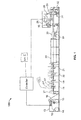
- Fig. 1 shows a printing press 100 in accordance with an embodiment of the present invention.
- Printing press 100 is a perfecting, offset press having a plate cylinder and blanket cylinder on both sides of the substrate for printing on both sides of the substrate at the same time.
- Printing units 18, 19, 20, 21 print on a substrate 16.
- Each printing unit 10 includes a plate cylinder 120 and a blanket cylinder 130.
- the printing press 100 may be non-perfecting web offset press.
- each plate cylinder 120 carries a printing plate 122 mounted thereon.
- the printing plates 122 may be secured to the plate cylinder 120 by devices known in the printing arts, for example, via reel rods or lock up slots.
- Each blanket cylinder 130 carries a printing blanket 132 mounted thereon.
- the blankets 130 may be sleeve shaped printing blankets.
- Each plate and blanket cylinder 120, 130 is connected to a motor M 126, 136, respectively. The torque of each plate cylinder motor is recorded, both when the plate cylinder is on impression, Ton ( Fig. 4 ), and when the plate cylinder is off impression, Toff ( Fig. 2 ).
- the radius rp of printing plate 122 and the width W of the printing plate 122 are input into the control system.
- the PLC will throw the subject printing unit off impression, stop the press, and post a fault message to the operator to replace the blanket.
- the range of acceptable operating nip force is first determined by testing or an operator may rely on empirical data 210.
- the measured parameters, Ton and Toff, are made 220 and sent to the PLC.
- the required static input parameters including the radius of the plate rp and the width W of the plate or press are also entered into the PLC 230.
- the nip force Fp is then determined 240.
- the nip force is checked against the acceptable operating range 250. If the nip force Fp is within the desired operating range, the press may continue printing 260. If the nip force Fp is outside the desired operating range, the blanket quality may be compromised so the printing unit(s) are thrown off impression, the press is brought to a stop and the operator receives a fault message to change or remedy the blanket cylinder 270.
Landscapes
- Chemical & Material Sciences (AREA)
- Analytical Chemistry (AREA)
- Engineering & Computer Science (AREA)
- Mechanical Engineering (AREA)
- Physics & Mathematics (AREA)
- General Physics & Mathematics (AREA)
- Inking, Control Or Cleaning Of Printing Machines (AREA)
Abstract
Description
- Priority is hereby claimed to
U.S. Provisional Application No. 61/977,920 - The present invention relates generally to printing presses and more particularly to blanket cylinders.
-
U.S. Patent No. 7,617,773 , hereby incorporated by reference herein, discloses a device for determining incorrectly sized or manufactured blankets. The device includes a first blanket on a first blanket cylinder independently driven by a first motor, a first controller for determining torque values of the first motor, a second blanket on a second blanket cylinder independently driven by a second motor, a second controller for determining torque values of the second motor. A processor determines the existence of a size difference between the first and second blankets as a function of the torque values of the first and second motors. -
U.S. Patent No. 6,433,499 , hereby incorporated by reference herein, discloses an apparatus for calibrating a tension transducer for a web that includes a pair of nip rollers and a motor for driving at least one of the pair of nip rollers, the motor having at least one roller output being a function of at least one of a motor torque and a motor velocity. A web tension transducer roll is located upstream of the nip rollers, the web tension transducer having a tension output being a function of the actual web tension of the web. A processor receives the at least one roller output and the tension output, the processor calculating a tension correction value as a function of the at least one roller output and the tension output. -
U.S. Patent No. 6,499,639 , hereby incorporated by reference herein, discloses a method for dynamically controlling a driver of a nip roller in a web printing press includes controlling the speed of the driver in a tension-control mode during a phase of printing press operation and in a velocity-control mode during another phase of printing press operation. The controlling of the speed of the driver in the tension-control mode is based on the tension in the web upstream of the nip roller so as to maintain the tension at a desired tension value. The controlling of the speed of the driver in the velocity-control mode is based on a predetermined driver velocity ratio for maintaining the web tension. - A preferred embodiment of the present invention will be elucidated with reference to the drawings, in which:
-
Fig. 1 shows a printing press according to a preferred embodiment of the present invention ; -
Fig. 2 shows a printing unit of the printing press shown inFig. 1 in a throw-off position; -
Fig. 3 shows a printing plate; -
Fig. 4 shows a printing unit of the printing press shown inFig. 1 in a throw-on position; and -
Fig. 5 is an illustrative flow chart for quantifying blanket performance in accordance with the present invention. - Torque differences between upper and lower blankets may be used to determine when a blanket should be swapped to another print unit or replaced. There are no known implementations that use nip force calculations as a metric to quantify blanket performance.
- Known embodiments do not set specific limits on nip forces to be applied by the blanket on the plate and do not make specific calculations of nip forces. Attempts have been made to monitor torque of the blanket cylinder during operation.
- A desired plate to blanket nip force allows the printing press to run continuously without either pulling the tail edge out, which occurs when nip forces are greater than the desired range, or pulling the lead edge out, which occurs when nip forces are below the desired range. A small negative nip force may be desirable in the direction that holds the plate on the cylinder.
- The method utilizes a design setpoint specific to the printing unit which may be based on the size of the cylinders. The design setpoint may be, for example, -1 pli. An acceptable range of nip force tolerance is determined that provides for acceptable printing and maintaining proper printing plate mounting while running the press on impression.
- The acceptable range of the nip force may be, for example, +/- 4 pli, with respect to the design setpoint. In practice, the nip force may be lower and still allow acceptable press performance. However, positive nip forces may result in plate tail removal from the cylinder.
- When the nip forces are outside the desired range the blanket can be removed and replaced before poor printing occurs or damage results in the printing unit or downstream printing units.
- The present invention utilizes known and measureable dynamic and static parameters to calculate blanket to plate nip forces and a desirable nip force range of operation which is determined empirically. Further refinement of the nip force range may establish optimized blanket print performance.
- The radius of the plate, rp, and the width of the press/plate, W, are required. These required static parameters are input to the control system as part of the job file or at the human machine interface HMI by an operator for a given print job.
- The measured parameters include the average plate torque on impression, Ton, and the average plate torque off impression, Toff. The measured parameters are available in the motion controller via the programmable logic controller, PLC, for the printing unit which knows the state of the printing unit, for example, on or off impression.
- The nip force Fp is calculated as follows:

- The desired nip force operating range is, for example, +/- 4 pli from the design setpoint, but may also be, for example, +/- 2 pli or +/- 1 pli or any combination in between, for example,
-2 pli ≤ Fp ≤ 0.25 pli. The control system response may be programmed so that if Fp > + 4pli + design setpoint or Fp < - 4 pli + design setpoint, the printing unit controller can throw the printing unit off impression, stop the press, and post a fault message to the operator to replace the blanket. Thus, the nip force is used to determine the quality of the blanket. An unacceptable nip force signifies the need for a new blanket. -
Fig. 1 shows aprinting press 100 in accordance with an embodiment of the present invention.Printing press 100 is a perfecting, offset press having a plate cylinder and blanket cylinder on both sides of the substrate for printing on both sides of the substrate at the same time.Printing units substrate 16. Each printing unit 10 includes aplate cylinder 120 and ablanket cylinder 130. In other preferred embodiments, theprinting press 100 may be non-perfecting web offset press. - As shown in
Figs. 2 to 4 , eachplate cylinder 120 carries aprinting plate 122 mounted thereon. Theprinting plates 122 may be secured to theplate cylinder 120 by devices known in the printing arts, for example, via reel rods or lock up slots. Eachblanket cylinder 130 carries aprinting blanket 132 mounted thereon. Theblankets 130 may be sleeve shaped printing blankets. Each plate andblanket cylinder Fig. 4 ), and when the plate cylinder is off impression, Toff (Fig. 2 ). - The radius rp of
printing plate 122 and the width W of theprinting plate 122 are input into the control system. The nip force is then calculated: Fp = -(Ton-Toff)/(rp x W). - Since the desired nip force operating range is, for example,+/- 4 pli with respect to the design setpoint, if Fp > design setpoint + 4 pli or Fp < design setpoint - 4 pli, the PLC will throw the subject printing unit off impression, stop the press, and post a fault message to the operator to replace the blanket.
- As shown in
Fig. 5 , the range of acceptable operating nip force is first determined by testing or an operator may rely onempirical data 210. The measured parameters, Ton and Toff, are made 220 and sent to the PLC. The required static input parameters including the radius of the plate rp and the width W of the plate or press are also entered into thePLC 230. The nip force Fp is then determined 240. The nip force is checked against theacceptable operating range 250. If the nip force Fp is within the desired operating range, the press may continue printing 260. If the nip force Fp is outside the desired operating range, the blanket quality may be compromised so the printing unit(s) are thrown off impression, the press is brought to a stop and the operator receives a fault message to change or remedy the blanket cylinder 270. - In the preceding specification, the invention has been described with reference to specific exemplary embodiments and examples thereof. It will, however, be evident that various modifications and changes may be made thereto without departing from the broader spirit and scope of invention as set forth in the claims that follow. The specification and drawings are accordingly to be regarded in an illustrative manner rather than a restrictive sense.
Claims (15)
- A method for determining or monitoring blanket performance in a printing press, the printing press including a plate cylinder having a printing plate transferring an image to a blanket on a blanket cylinder for printing on a substrate, the method comprising the steps of:determining an acceptable range of nip force between a plate cylinder and a blanket cylinder in a printing unit;calculating the nip force (Fp) between the plate cylinder and blanket cylinder; anddetermining or monitoring blanket performance based on the nip force with respect to the acceptable range of nip force.
- The method as recited in claim 1 further comprising the steps of:measuring the printing plate radius (rp) and printing plate width (W);measuring the torque of the plate cylinder when the plate cylinder and blanket cylinder are on impression (Ton); andmeasuring the torque of the plate cylinder when the plate cylinder and blanket cylinder are off impression (Toff).
- The method as recited in claim 2 wherein the nip force is a function of the plate radius (rp), printing plate width (W), on impression torque (Ton) and off impression torque (Toff).
- The method as recited in any one of the previous claims wherein an acceptable range of nip force is determined during testing.
- The method as recited in any one of the previous claims further comprising the step of:providing a design setpoint for a desired nip force in the printing press.
- The method as recited in claim 5 wherein the design setpoint is -1 pli.
- The method as recited in any one of the previous claims wherein the acceptable range of nip force is -4 pli ≤ Fp ≤ 4 pli, preferably -2 pli ≤ Fp ≤ 0.25 pli, and most preferably -1 pli ≤ Fp ≤ 0 pli.
- The method as recited in any one of claims 1 to 6 wherein an acceptable range of nip force is determined empirically.
- The method as recited in any one of the previous claims wherein if the calculated nip force is within the acceptable range, the printing press continues printing.
- The method as recited in any one of the previous claims wherein if the calculated nip force is outside of the acceptable range, the printing press moves into a throw off position.
- A printing press comprising:a plate mounted on a plate cylinder driven by a first motor;a blanket mounted on a blanket cylinder;a controller calculating a nip force between the blanket cylinder and plate cylinder;the controller throwing off the first plate cylinder and first blanket cylinder if the nip force is outside a predetermined range.
- The printing press recited in claim 11 wherein the controller determines torque values of the first motor when the plate cylinder is on impression and when the plate cylinder is off impression.
- The printing press recited in claim 11 or 12, wherein the nip force is a function of a radius of the printing plate (rp), a width of the printing plate (W), and torque values of the first motor when the plate cylinder is on impression (Ton) and off impression (Toff).
- The method as recited in claim 3 or the printing press recited in claim 13 wherein the nip force Fp is calculated using the following formula: Fp = -(Ton-Toff)/(rp x W).
- The method as recited in claim 5 or the printing press recited in claim 11 wherein the acceptable range of nip force is +/-4 pli with respect to a/the design setpoint.
Applications Claiming Priority (2)
| Application Number | Priority Date | Filing Date | Title |
|---|---|---|---|
| US201461977920P | 2014-04-10 | 2014-04-10 | |
| US14/681,765 US9555614B2 (en) | 2014-04-10 | 2015-04-08 | Method for quantifying blanket performance and printing press |
Publications (1)
| Publication Number | Publication Date |
|---|---|
| EP2930026A1 true EP2930026A1 (en) | 2015-10-14 |
Family
ID=52814906
Family Applications (1)
| Application Number | Title | Priority Date | Filing Date |
|---|---|---|---|
| EP15162968.0A Withdrawn EP2930026A1 (en) | 2014-04-10 | 2015-04-09 | Method for quantifying blanket performance and printing press |
Country Status (2)
| Country | Link |
|---|---|
| US (1) | US9555614B2 (en) |
| EP (1) | EP2930026A1 (en) |
Families Citing this family (1)
| Publication number | Priority date | Publication date | Assignee | Title |
|---|---|---|---|---|
| JP7135991B2 (en) * | 2019-04-25 | 2022-09-13 | トヨタ自動車株式会社 | Calibration judgment device and calibration judgment method |
Citations (8)
| Publication number | Priority date | Publication date | Assignee | Title |
|---|---|---|---|---|
| JPS62165135A (en) * | 1986-01-17 | 1987-07-21 | Mitsubishi Heavy Ind Ltd | Printing pressure measuring instrument for printing machine |
| US6433499B1 (en) | 2000-11-29 | 2002-08-13 | Heidelberger Druckmaschinen Ag | Device and method for automatic tension transducer calibration |
| US6499639B2 (en) | 2001-02-12 | 2002-12-31 | Heidelberger Druckmaschinen Ag | Method and apparatus for dynamically controlling a web printing press |
| DE102005023482B3 (en) * | 2005-05-21 | 2006-11-16 | Koenig & Bauer Ag | Diagnosis process for rubbercloth involves monitoring drive current of drive motor of rubber cylinder and drawing conclusions about condition of rubbercloths |
| WO2008028516A1 (en) * | 2006-09-05 | 2008-03-13 | Metso Paper, Inc. | Method and device for nip condition measurement |
| US7617773B2 (en) | 2006-06-01 | 2009-11-17 | Goss International Americas, Inc. | Blanket size verification using drive torque feedback |
| DE102010006782A1 (en) * | 2010-02-04 | 2011-08-04 | Heidelberger Druckmaschinen AG, 69115 | Device for measurement of force between cylindrical bodies of offset printing machine, has piezoelectric films arranged on top of each other on running surface, and layers forming outputs with poles and connected with control device |
| US20120193870A1 (en) * | 2011-01-31 | 2012-08-02 | Elad Taig | Sheet Processing |
Family Cites Families (7)
| Publication number | Priority date | Publication date | Assignee | Title |
|---|---|---|---|---|
| DE19822662C2 (en) * | 1998-05-20 | 2003-12-24 | Roland Man Druckmasch | Process for color reproduction on an image data oriented printing machine |
| US6272986B1 (en) * | 1999-10-15 | 2001-08-14 | Howard W. DeMoore | Retractable impression cylinder inking/coating apparatus having ferris movement between printing units |
| US6418847B1 (en) * | 1999-10-20 | 2002-07-16 | Ward Holding Company | Printing machine with plate thickness compensation |
| US7344105B2 (en) * | 2004-06-03 | 2008-03-18 | The Procter & Gamble Company | Method of controlling the winding of a roll of web material |
| DE502007001508D1 (en) * | 2006-12-01 | 2009-10-22 | Koenig & Bauer Ag | METHOD FOR OPERATING A NINE CYLINDER SATELLITE PRESSURE UNIT |
| JP2008212826A (en) * | 2007-03-05 | 2008-09-18 | Komori Corp | Method for adjusting contact pressure of liquid application machine and contact pressure adjustment device for liquid application machine |
| US8807034B2 (en) * | 2012-04-13 | 2014-08-19 | Xerox Corporation | Method and apparatus for spreader nip balancing in a print system |
-
2015
- 2015-04-08 US US14/681,765 patent/US9555614B2/en not_active Expired - Fee Related
- 2015-04-09 EP EP15162968.0A patent/EP2930026A1/en not_active Withdrawn
Patent Citations (8)
| Publication number | Priority date | Publication date | Assignee | Title |
|---|---|---|---|---|
| JPS62165135A (en) * | 1986-01-17 | 1987-07-21 | Mitsubishi Heavy Ind Ltd | Printing pressure measuring instrument for printing machine |
| US6433499B1 (en) | 2000-11-29 | 2002-08-13 | Heidelberger Druckmaschinen Ag | Device and method for automatic tension transducer calibration |
| US6499639B2 (en) | 2001-02-12 | 2002-12-31 | Heidelberger Druckmaschinen Ag | Method and apparatus for dynamically controlling a web printing press |
| DE102005023482B3 (en) * | 2005-05-21 | 2006-11-16 | Koenig & Bauer Ag | Diagnosis process for rubbercloth involves monitoring drive current of drive motor of rubber cylinder and drawing conclusions about condition of rubbercloths |
| US7617773B2 (en) | 2006-06-01 | 2009-11-17 | Goss International Americas, Inc. | Blanket size verification using drive torque feedback |
| WO2008028516A1 (en) * | 2006-09-05 | 2008-03-13 | Metso Paper, Inc. | Method and device for nip condition measurement |
| DE102010006782A1 (en) * | 2010-02-04 | 2011-08-04 | Heidelberger Druckmaschinen AG, 69115 | Device for measurement of force between cylindrical bodies of offset printing machine, has piezoelectric films arranged on top of each other on running surface, and layers forming outputs with poles and connected with control device |
| US20120193870A1 (en) * | 2011-01-31 | 2012-08-02 | Elad Taig | Sheet Processing |
Also Published As
| Publication number | Publication date |
|---|---|
| US9555614B2 (en) | 2017-01-31 |
| US20150290925A1 (en) | 2015-10-15 |
Similar Documents
| Publication | Publication Date | Title |
|---|---|---|
| JP4276719B2 (en) | Device for synchronizing printing devices and method for synchronously delivering printed sheets | |
| EP2703160A1 (en) | Strain controlled infeed | |
| KR20170132079A (en) | Multi-Color Printing System and Controlling Method | |
| US20150175378A1 (en) | Sheet processing apparatus and image forming apparatus | |
| EP2072258A1 (en) | Printer and its operating method | |
| EP2860032B1 (en) | Closed loop ink thickness control system with reduced substrate waste in a printing press | |
| EP2412527A2 (en) | Observation-enhanced virtual master system for a printing press | |
| EP2930026A1 (en) | Method for quantifying blanket performance and printing press | |
| US9789680B2 (en) | Method for adjusting the print repeat length of a print image in a multicolor rotary printing machine | |
| CN105034565A (en) | Packaging bag transfer printing device | |
| US8869699B2 (en) | Method of controlling inking units in case of printing speed changes | |
| CN103660531B (en) | Alignment adjustment during printing machine adjustment process | |
| US20080173195A1 (en) | Offset printing press with cutting register adjustment and corresponding method | |
| US20120145020A1 (en) | Device for regulating the application of dampening solution and ink in a printing press | |
| US8279485B2 (en) | Register regulation in a printing press | |
| JP4357908B2 (en) | How to compensate for misregistration when operating a printing press | |
| JP7664193B2 (en) | Printing control device | |
| US20140053749A1 (en) | Digital Printing Device for the Dynamic Printing of a Statically Printed Substrate Web and Reel-Fed Printing Press | |
| EP3196019B1 (en) | Method and device for adjusting contact pressure of intaglio printer wiping roller | |
| JP5121617B2 (en) | Start of final printing with less fountain solution applied | |
| CN103909724A (en) | Registration System For Variable Repeat Press | |
| DE102007034835A1 (en) | Shaftless printing machine e.g. cardboard printing machine, operating method, involves presetting processing length of printed product by speeds of driven processing axle i.e. ink-transferring axle | |
| KR101152775B1 (en) | True rolling for Electronic element production device | |
| US7617773B2 (en) | Blanket size verification using drive torque feedback | |
| JP4388321B2 (en) | Control method and control apparatus for rotary press |
Legal Events
| Date | Code | Title | Description |
|---|---|---|---|
| PUAI | Public reference made under article 153(3) epc to a published international application that has entered the european phase |
Free format text: ORIGINAL CODE: 0009012 |
|
| AK | Designated contracting states |
Kind code of ref document: A1 Designated state(s): AL AT BE BG CH CY CZ DE DK EE ES FI FR GB GR HR HU IE IS IT LI LT LU LV MC MK MT NL NO PL PT RO RS SE SI SK SM TR |
|
| AX | Request for extension of the european patent |
Extension state: BA ME |
|
| 17P | Request for examination filed |
Effective date: 20160317 |
|
| RBV | Designated contracting states (corrected) |
Designated state(s): AL AT BE BG CH CY CZ DE DK EE ES FI FR GB GR HR HU IE IS IT LI LT LU LV MC MK MT NL NO PL PT RO RS SE SI SK SM TR |
|
| STAA | Information on the status of an ep patent application or granted ep patent |
Free format text: STATUS: EXAMINATION IS IN PROGRESS |
|
| 17Q | First examination report despatched |
Effective date: 20180518 |
|
| RAP1 | Party data changed (applicant data changed or rights of an application transferred) |
Owner name: MANROLAND GOSS WEB SYSTEMS GMBH |
|
| STAA | Information on the status of an ep patent application or granted ep patent |
Free format text: STATUS: THE APPLICATION IS DEEMED TO BE WITHDRAWN |
|
| 18D | Application deemed to be withdrawn |
Effective date: 20221101 |