EP2929860A1 - Device for implantation in the heart of a mammal - Google Patents
Device for implantation in the heart of a mammal Download PDFInfo
- Publication number
- EP2929860A1 EP2929860A1 EP14163731.4A EP14163731A EP2929860A1 EP 2929860 A1 EP2929860 A1 EP 2929860A1 EP 14163731 A EP14163731 A EP 14163731A EP 2929860 A1 EP2929860 A1 EP 2929860A1
- Authority
- EP
- European Patent Office
- Prior art keywords
- stent
- valve
- stent graft
- heart
- tubular
- Prior art date
- Legal status (The legal status is an assumption and is not a legal conclusion. Google has not performed a legal analysis and makes no representation as to the accuracy of the status listed.)
- Granted
Links
Images


Classifications
-
- A—HUMAN NECESSITIES
- A61—MEDICAL OR VETERINARY SCIENCE; HYGIENE
- A61F—FILTERS IMPLANTABLE INTO BLOOD VESSELS; PROSTHESES; DEVICES PROVIDING PATENCY TO, OR PREVENTING COLLAPSING OF, TUBULAR STRUCTURES OF THE BODY, e.g. STENTS; ORTHOPAEDIC, NURSING OR CONTRACEPTIVE DEVICES; FOMENTATION; TREATMENT OR PROTECTION OF EYES OR EARS; BANDAGES, DRESSINGS OR ABSORBENT PADS; FIRST-AID KITS
- A61F2/00—Filters implantable into blood vessels; Prostheses, i.e. artificial substitutes or replacements for parts of the body; Appliances for connecting them with the body; Devices providing patency to, or preventing collapsing of, tubular structures of the body, e.g. stents
- A61F2/02—Prostheses implantable into the body
- A61F2/04—Hollow or tubular parts of organs, e.g. bladders, tracheae, bronchi or bile ducts
- A61F2/06—Blood vessels
- A61F2/07—Stent-grafts
-
- A—HUMAN NECESSITIES
- A61—MEDICAL OR VETERINARY SCIENCE; HYGIENE
- A61B—DIAGNOSIS; SURGERY; IDENTIFICATION
- A61B90/00—Instruments, implements or accessories specially adapted for surgery or diagnosis and not covered by any of the groups A61B1/00 - A61B50/00, e.g. for luxation treatment or for protecting wound edges
- A61B90/39—Markers, e.g. radio-opaque or breast lesions markers
-
- A—HUMAN NECESSITIES
- A61—MEDICAL OR VETERINARY SCIENCE; HYGIENE
- A61F—FILTERS IMPLANTABLE INTO BLOOD VESSELS; PROSTHESES; DEVICES PROVIDING PATENCY TO, OR PREVENTING COLLAPSING OF, TUBULAR STRUCTURES OF THE BODY, e.g. STENTS; ORTHOPAEDIC, NURSING OR CONTRACEPTIVE DEVICES; FOMENTATION; TREATMENT OR PROTECTION OF EYES OR EARS; BANDAGES, DRESSINGS OR ABSORBENT PADS; FIRST-AID KITS
- A61F2/00—Filters implantable into blood vessels; Prostheses, i.e. artificial substitutes or replacements for parts of the body; Appliances for connecting them with the body; Devices providing patency to, or preventing collapsing of, tubular structures of the body, e.g. stents
- A61F2/02—Prostheses implantable into the body
- A61F2/24—Heart valves ; Vascular valves, e.g. venous valves; Heart implants, e.g. passive devices for improving the function of the native valve or the heart muscle; Transmyocardial revascularisation [TMR] devices; Valves implantable in the body
- A61F2/2412—Heart valves ; Vascular valves, e.g. venous valves; Heart implants, e.g. passive devices for improving the function of the native valve or the heart muscle; Transmyocardial revascularisation [TMR] devices; Valves implantable in the body with soft flexible valve members, e.g. tissue valves shaped like natural valves
- A61F2/2418—Scaffolds therefor, e.g. support stents
-
- A—HUMAN NECESSITIES
- A61—MEDICAL OR VETERINARY SCIENCE; HYGIENE
- A61B—DIAGNOSIS; SURGERY; IDENTIFICATION
- A61B90/00—Instruments, implements or accessories specially adapted for surgery or diagnosis and not covered by any of the groups A61B1/00 - A61B50/00, e.g. for luxation treatment or for protecting wound edges
- A61B90/39—Markers, e.g. radio-opaque or breast lesions markers
- A61B2090/3966—Radiopaque markers visible in an X-ray image
-
- A—HUMAN NECESSITIES
- A61—MEDICAL OR VETERINARY SCIENCE; HYGIENE
- A61F—FILTERS IMPLANTABLE INTO BLOOD VESSELS; PROSTHESES; DEVICES PROVIDING PATENCY TO, OR PREVENTING COLLAPSING OF, TUBULAR STRUCTURES OF THE BODY, e.g. STENTS; ORTHOPAEDIC, NURSING OR CONTRACEPTIVE DEVICES; FOMENTATION; TREATMENT OR PROTECTION OF EYES OR EARS; BANDAGES, DRESSINGS OR ABSORBENT PADS; FIRST-AID KITS
- A61F2/00—Filters implantable into blood vessels; Prostheses, i.e. artificial substitutes or replacements for parts of the body; Appliances for connecting them with the body; Devices providing patency to, or preventing collapsing of, tubular structures of the body, e.g. stents
- A61F2/02—Prostheses implantable into the body
- A61F2/24—Heart valves ; Vascular valves, e.g. venous valves; Heart implants, e.g. passive devices for improving the function of the native valve or the heart muscle; Transmyocardial revascularisation [TMR] devices; Valves implantable in the body
- A61F2/2475—Venous valves
-
- A—HUMAN NECESSITIES
- A61—MEDICAL OR VETERINARY SCIENCE; HYGIENE
- A61F—FILTERS IMPLANTABLE INTO BLOOD VESSELS; PROSTHESES; DEVICES PROVIDING PATENCY TO, OR PREVENTING COLLAPSING OF, TUBULAR STRUCTURES OF THE BODY, e.g. STENTS; ORTHOPAEDIC, NURSING OR CONTRACEPTIVE DEVICES; FOMENTATION; TREATMENT OR PROTECTION OF EYES OR EARS; BANDAGES, DRESSINGS OR ABSORBENT PADS; FIRST-AID KITS
- A61F2220/00—Fixations or connections for prostheses classified in groups A61F2/00 - A61F2/26 or A61F2/82 or A61F9/00 or A61F11/00 or subgroups thereof
- A61F2220/0025—Connections or couplings between prosthetic parts, e.g. between modular parts; Connecting elements
-
- A—HUMAN NECESSITIES
- A61—MEDICAL OR VETERINARY SCIENCE; HYGIENE
- A61F—FILTERS IMPLANTABLE INTO BLOOD VESSELS; PROSTHESES; DEVICES PROVIDING PATENCY TO, OR PREVENTING COLLAPSING OF, TUBULAR STRUCTURES OF THE BODY, e.g. STENTS; ORTHOPAEDIC, NURSING OR CONTRACEPTIVE DEVICES; FOMENTATION; TREATMENT OR PROTECTION OF EYES OR EARS; BANDAGES, DRESSINGS OR ABSORBENT PADS; FIRST-AID KITS
- A61F2230/00—Geometry of prostheses classified in groups A61F2/00 - A61F2/26 or A61F2/82 or A61F9/00 or A61F11/00 or subgroups thereof
- A61F2230/0063—Three-dimensional shapes
- A61F2230/0069—Three-dimensional shapes cylindrical
-
- A—HUMAN NECESSITIES
- A61—MEDICAL OR VETERINARY SCIENCE; HYGIENE
- A61F—FILTERS IMPLANTABLE INTO BLOOD VESSELS; PROSTHESES; DEVICES PROVIDING PATENCY TO, OR PREVENTING COLLAPSING OF, TUBULAR STRUCTURES OF THE BODY, e.g. STENTS; ORTHOPAEDIC, NURSING OR CONTRACEPTIVE DEVICES; FOMENTATION; TREATMENT OR PROTECTION OF EYES OR EARS; BANDAGES, DRESSINGS OR ABSORBENT PADS; FIRST-AID KITS
- A61F2250/00—Special features of prostheses classified in groups A61F2/00 - A61F2/26 or A61F2/82 or A61F9/00 or A61F11/00 or subgroups thereof
- A61F2250/0014—Special features of prostheses classified in groups A61F2/00 - A61F2/26 or A61F2/82 or A61F9/00 or A61F11/00 or subgroups thereof having different values of a given property or geometrical feature, e.g. mechanical property or material property, at different locations within the same prosthesis
- A61F2250/0039—Special features of prostheses classified in groups A61F2/00 - A61F2/26 or A61F2/82 or A61F9/00 or A61F11/00 or subgroups thereof having different values of a given property or geometrical feature, e.g. mechanical property or material property, at different locations within the same prosthesis differing in diameter
Definitions
- the present invention relates to a device for implantation in the heart of a mammal, with a generally tubular shape, and having a longitudinal axis, a first end and a second end, and a lumen permitting blood flow there through.
- the present invention also relates to the use of such a device for treating tricuspid regurgitation in a mammal.
- the human heart is subdivided by septa into right and left halves, and a constriction subdivides each half of the organ into two cavities, the upper cavity being called the atrium, the lower the ventricle, respectively.
- the heart consists of four chambers, i.e., right and left atria, and right and left ventricles.
- the four valves of the human heart i.e. the aortic, mitral, tricuspid and pulmonary valves, a one-way blood flow through the (healthy) heart is maintained.
- the four heart valves make sure that blood always flows freely in a forward direction and that there is no backward leakage.
- valve disorders such as stenosis, which occurs when a heart valve doesn't fully open due to stiff or fused leaflets preventing them from opening properly, or prolapse, where the valve flaps do not close smoothly or evenly but collapse backwards into the heart chamber they are supposed to be sealing off.
- Valve regurgitation (backward flow) is also common problem, and occurs when a heart valve doesn't close tightly, as a consequence of which the valve does not seal and blood leaks backwards across the valve.
- This condition also called valvular insufficiency - reduces the heart's pumping efficiency: When the heart contracts blood is pumped forward in the proper direction but is also forced backwards through the damaged valve. As the leak worsens, the heart has to work harder to make up for the leaky valve and less blood may flow to the rest of the body.
- the condition is called tricuspid regurgitation, pulmonary regurgitation, mitral regurgitation, or aortic regurgitation.
- Tricuspid insufficiency may be asymptomatic, however, common symptoms are, e.g. hepatomegaly, edema and jugular distenosis.
- Human heart valves may be replaced with mechanical valves, or with specially prepared heart valves from human or animal donors (known as bioprosthetic or tissue valves).
- Bioprosthetic valves are sometimes called tissue valves and made from specially treated natural (“biological") valves. These valves come from two sources: human donors and animals. Valves from animal sources (usually cows or pigs) are very similar to those found in the human heart.
- Surgical repair or replacement of the tricuspid valve carries a high operative mortality.
- tricuspid regurgitation is rectified either by replacement of the total valve with an replacement valve or by constriction of the valve ring with an annular remodeling ring, which involves rigid or flexible annular bands, which are intended to reduce annular size.
- transcatheter techniques and devices for tricuspid regurgitation treatment have recently been developed; however, only limited experimental transcatheter data is available.
- WO 2012/018599 A1 discloses a two valve caval stent for functional replacement of an incompetent tricuspid valve, which may be delivered by transcatheter placement. It comprises two stents connected by a bridge spanning the right atrium, and two valves anchored by the stents in the superior and inferior vena cavas .
- WO 2004/093638 discloses a device and methods for treatment of tricuspid regurgitation, where a first and a second stented valve are implanted at the superior and inferior vena cava.
- the device is intended to permit blood flow towards the right atrium of a patient and prevent blood flow in the opposite direction.
- a device for implantation in the heart of a mammal with a generally tubular shape, and having a longitudinal axis, a first end and a second end, and a lumen permitting blood flow there through
- the device comprises: (i) a first tubular stent member, sized and configured for implantation within the superior vena cava, and having a length, a diameter, a first and a second end, (ii) a second tubular stent member, sized and configured for implantation within the inferior vena cava, and having a length, a diameter, a first and a second end, wherein the said second tubular stent member does not comprise a covering, (iii) a tubular stent graft member, having a length, a diameter, a first and a second stent graft member end, and comprising a covering being attached to a stent element, wherein the tubular stent graf
- the device according to the invention spans a path through the heart from the vena cava superior to the vena cava inferior while simultaneously guaranteeing, by means of the fully functioning stented valve member, that the one-way blood flow from the right atrium to the right ventricle is maintained, and a backflow of the blood from the right ventricle into the right atrium can be prevented, thus effectively treating the tricuspid insufficiency.
- the device according to the invention is easy to handle and deploy since only once device needs to be deployed - contrary to the devices currently available which either necessitate the deployment of two separate valves in the vena cava superior and vena cava inferior, or which apply a replacement annular ring of the natural valve.
- the overall deployment and valve replacement procedure and, thus, the overall surgical operation, can be fast and easily accomplished.
- a “stent” is to be understood and referred to as a cylindrical or tubular, radially-expandable metal frame or body and means any device or structure that adds rigidity, expansion force, or support to a prosthesis
- “stent graft” refers to a prosthesis comprising a stent and a graft material associated therewith that forms a fluid-tight or substantially fluid-tight lumen through at least a portion of its length.
- the cylindrical/tubular body of stents/stent grafts is inserted into the vessel/organ to be treated and is expanded or self-expandable and fixed or fixes itself at the appropriate site in order to keep open the lumen of the vessel/organ.
- the metal frame of the stent members and elements of the device according to the invention may be laser cut or woven or braided or knitted or comprise an otherwise interconnected metal mesh.
- a "graft” material is a cylindrical liner that may be disposed on the stent's interior, exterior or both.
- a wide variety of attachment mechanisms are available to join the stent and graft together, including but not limited to, sutures, adhesive bonding, heat welding, and ultrasonic welding.
- a "covering” also may designate or is designating a graft material attached to a stent member, which is why a "stent graft" is presently, and throughout the relevant field, also designated as “covered stent” or “covered stent graft”.
- Stent grafts generally comprise, for example, a series of stent elements or, respectively, a wire framework made of a self-expanding material.
- stents are understood to be individual self-expanding elements.
- the self-expanding elements or, respectively, the wire framework are connected to each other by a textile or PTFE tube, called a graft sleeve, to form a functional unit and in this way, analogous to the stents described above, they form a tubular body that supports the vessel walls
- the stent elements of the stent graft may represent single metal rings forming a metal mesh, the rings meandering circumferentially and being disposed successively in the graft member's longitudinal axis/direction, wherein the metal rings have a Z-shaped profile with pointed arches pointing alternately toward the proximal end and distal end of the device.
- the tubular stent graft member located between the two, i.e. the first and second tubular stent members, forms a fluid-tight or substantially fluid-tight sealing, only permitting unidirectional blood flow towards the right ventricle via the stented valve member mounted thereupon.
- the second stent member does not comprise a covering or graft material, thus providing an anchor for the device in the vena cava inferior, whilst guaranteeing that blood flow into vessels which branch off the vena cava inferior are not blocked.
- the first stent member may be covered or not, and is, according to a preferred embodiment, not covered by a graft material/covering. Accordingly, the first stent member provides for anchoring means of the device within the vena cava superior.
- the stent/stent member according to the invention can be made of or comprise any suitable material, including but not limited to biocompatible metals, implantable quality stainless steel wires, nickel and titanium alloys, in particular nitinol, and biocompatible plastics attached to a graft.
- the graft material is a biocompatible fabric, including but not limited to woven, knitted or otherwise fabricated material, such as polyester, such as polyethylene terephthalate, fluorinated polymers, such as polytetrafluoroethylene (PTFE), expanded PTFE (ePTFE), polyvinylidene fluoride, polysiloxane, including polydimethyl siloxane, polyurethanes, including polyetherurethanes, polylactide, polyglycolide and copolymers thereof.
- PTFE polytetrafluoroethylene
- ePTFE expanded PTFE
- polyvinylidene fluoride polysiloxane, including polydimethyl siloxane
- polyurethanes including polyetherurethanes
- polylactide polyglycolide and copolymers thereof.
- materials that are not inherently biocompatible may be used when previously subjected to surface modifications in order to render the materials biocompatible.
- biomaterial as mammal i.e. bovine, porcine
- SIS submucosa of small intestine
- any other cross linked bio-material tissue suitable to be used as a graft material may be employed.
- the (covered) stent graft member can be made of any suitable material, including but not limited to polytetrafluoroethylene (ePTFE) lined nickel-titanium alloy (nitinol) stent.
- ePTFE polytetrafluoroethylene
- nitinol nickel-titanium alloy
- the components of the device i.e. the first and second stent members and the stent graft member comprising the stented valve member can be variously sized (i.e.: length, diameter, etc.) as suitable for an intended use and as depending on the respective condition of the patient's heart, and are preferably larger in diameter than the inner vessel diameter the members of the device are to be placed in.
- the covering and/or the stent element of the stent graft member at the site where the stented valve member is attached to the stent graft member allow for a fluid path into and out of the valve in the direction towards the atrium. This can be accomplished by means of an opening in the covering, sized and fitted for the stented valve member attached thereto, and/or meshes of the stent graft's stent element.
- the device further comprises visualization elements, in particular radio-opaque markers, wherein the visualization elements are attached to the device at one or more of the following elements of the device: at the site where the stent graft member's first end is attached to the second stent member's second end, at the site where the stent graft member's second end is attached to the first stent member's first end, and/or at the fixation site of the stented valve member to the stent graft member.
- visualization elements in particular radio-opaque markers
- visualization elements shall mean any suitable aid attached or otherwise provided on the device facilitating the accurate placement of the device.
- those visualization elements are radiopaque markers comprising or consisting of any suitable material, such as, e.g., gold, tantalum, platinum.
- the visualization elements may, e.g., take the form of gold bands or singular elements at the respective preferred locations of the device, or represent directional elements or markers, e.g. in the shape of a letter, such as "E” or "S” or “J” or “L” or any other suitable letter or form for indicating direction and orientation of the device.
- the visualization elements are, in one embodiment, arranged over the circumference at the site where the stent graft element and the tubular stent elements are attached to one another, and/or at the site where the stented valve member is attached to the stent graft element.
- At least one of the following, the first stent member, the second stent member, the stent element of the stent graft member, and/or the stent element of the stented valve member is/are self-expanding, wherein the device is configured, such, that it is convertible from a compressed state for introducing the device into a heart of a mammal to an expanded state within the heart.
- the stent elements of the device are preferably self-expanding, although the device - or rather its stent/stent graft members/elements, may also be, e.g., balloon-expandable.
- the stent members allow for radial force fixation within the vena cava .
- the device of the invention along its longitudinal axis, varies in its diameter.
- the different diameters and conditions of the vessels, in particular the vena cava can be respected.
- the first stent member's diameter is, in the expanded state of the device, smaller than the second stent member's diameter.
- the diameters are reflecting the larger diameter of the vena cava inferior as compared to the diameter of the vena cava superior.
- the diameter of each, the first stent member, the second stent member and/or the stent graft member vary along the respective lengths for the members.
- the valve is a biological valve comprising one, two or three leaflets, preferably three.
- the healthy human tricuspid valve comprises three leaflets, or cusps, named after their positions: anterior, posterior and septal.
- the valve of the stented valve mounted on the stent graft member also comprises three leaflets, and thus, represents a tricuspid valve, whilst also a valve having only two leaflets and, having, thus, a "bicuspid” architecture, or with even one leaflet, i.e. a monocuspid valve, can be used with the device according to the invention.
- Such valves can be created from human or animal donors. They can be created, e.g., from pericardium of human or any mammal, or from native leaflets from the heart or veins, or from any other biological material suitable for the intended purpose. Generally speaking, such valves are also called biological or tissue valves - as contrary to mechanical valves.
- the biological valve comprises or consists of a material that is selected from animal pericardium, in particular porcine, bovine, equine pericardium, or from native leaflets from human heart or veins.
- the invention also relates to the use of the device according to the invention for treating tricuspid regurgitation in a mammal, as well as to a method for treating tricuspid regurgitation in a mammal, comprising the step of delivering and/or implanting a device according to the invention to a position within the heart of a patient in need thereof in order to replace or support the native tricuspid valve of said patient.
- the device according to the invention can be either surgically implanted or delivered by transcatheter methods. In the latter case, i.e. with a transcatheter method, the device according to the invention is loaded onto a suitable deployment catheter, there being compressed by a retractable sheath or tube. The deployment catheter is inserted into the heart of a patient whose tricuspid valve needs replacement or support.
- the deployment catheter having the device according to the invention loaded thereon in a compressed state is advanced via the jugular vein into the vena cava superior into the right atrium and into the vena cava inferior, as far as the second tubular stent member is placed into the vena cava inferior, the stent graft member within the right atrium and the first tubular stent member into the vena cava superior.
- the deployment catheter having the device according to the invention loaded thereon in a compressed state can be advanced via the femoral vein into the vena cava inferior into the right atrium and into the vena cava superior, as far as the first tubular stent member is placed into the vena cava superior, the stent graft member within the right atrium and the second tubular stent member into the vena cava inferior. Correct placement can be monitored via the visualization elements.
- the sheath or the otherwise compressing means is retracted to stepwise release the device according to the invention, upon which action the stent members of the device can expand and fixate the device in the vena cava superior and inferior, respectively.
- the stented valve element mounted thereon can operate as soon as the compressing means are retracted.
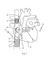
- a human heart 50 is depicted, having a right atrium 54, a right ventricle 55, a left atrium 56 and a left ventricle 57. Also depicted in fig. 1 is a portion of the vena cava superior 52, entering the heart 50 via the right atrium 54, and a portion of the vena cava inferior 53.
- the superior vena cava 52 returns the blood from the upper half of the body, and opens into the upper and back part of the right atrium 54, the direction of its orifice 52a being downward and forward. Its orifice 52a has no valve.
- the inferior vena cava 53 which has a larger diameter than the superior vena cava 52, returns the blood from the lower half of the body, and opens into the lowest part of the right atrium 54, its orifice 53a being directed upward and backward, and guarded by a rudimentary valve, the valve of the inferior vena cava (Eustachian valve, not shown).
- the right ventricle 55 has a triangular in form, and extends from the right atrium 54 to near the apex 59 of the heart 50.
- the right atrioventricular orifice (not depicted in fig. 1 ) is the large oval aperture of communication between the right atrium 54 and ventricle 55, and is guarded by the tricuspid valve 60.
- the opening 61 of the pulmonary artery 62 is circular in form, and is placed above and to the left of the atrioventricular opening; it is guarded by the pulmonary valves 63.
- the tricuspid valve 60 consists of three about triangular cusps or segments or leaflets 64, the anterior, posterior and medial or septal cusp. Their bases are attached to a fibrous ring (not depicted in fig. 1 ) surrounding the atrioventricular orifice and are also joined to each other so as to form a continuous annular membrane. Their atrial surfaces are directed toward the blood current from the atrium 54, while their ventricular surfaces are directed toward the wall of the ventricle 55; together with the apices and margins of the cusps, they give attachment for the chordae tendineae (not depicted in fig. 1 ).
- the function of the tricuspid valve is to prevent back flow of blood into the right atrium 54; arrows 70 and 71 indicate normal blood flow into the right atrium 54.
- the left atrium 56 is smaller than the right atrium 54.
- the left ventricle 57 is longer and more conical in shape than the right ventricle 55.
- the left atrioventricular opening (mitral orifice, not depicted in fig. 1 ) is placed to the left of the aortic orifice 65, and is guarded by the bicuspid or mitral valve 66.
- the aortic opening 65 is a circular aperture, in front and to the right of the atrioventricular opening, and its orifice is guarded by the three aortic valves 67.
- Reference number 68 designates the aorta.
- Tricuspid regurgitation is not uncommon in the tricuspid valve 60, and means that blood from the right ventricle 55 flows back into the right atrium 54 upon contraction of the right ventricle 55 due to the tricuspid valve 60 not properly closing.
- tricuspid regurgitation is to be treated, and placement of an exemplary embodiment of the device according to the invention is depicted in the attached fig. 2 .
- Fig. 2 shows the schematic drawing of the heart as already depicted in fig. 1 .
- fig. 2 does not include all of the reference numbers as designated in fig. 1 , but is meant to show the same features of the human heart 50.
- the device 10 according to the invention is placed in the expanded state in the human heart 50.
- the device as such is shown in more detail in fig. 3 , and in the following it will be made reference to both, fig. 2 and 3 ; for the sake of better understanding, not all of the features of the device designated in fig. 3 are designated in fig. 2 , however, the features are nevertheless the same.
- Device 10 comprises a general tubular shape 11, and has a longitudinal axis 12, a first end 13 and a second end 14, with a lumen 15 extending in between and permitting blood flow there through.
- the device 10 comprises a first tubular stent member 16, a second stent member 22, and a stent graft member 30 placed in between the first and second tubular stent member.
- the first tubular stent member 16 has a length 17, a diameter 18, and a first and a second end 19, 20, respectively. Length 17 and diameter 18 of the first tubular stent member 16 are such that the stent member 16 can securely anchor the device's 10 first end 13 within the vena cava superior 52.
- the second stent member 22 has a length 23, a diameter 24, a first and a second end 25, 26, respectively. Length 23 and diameter 24 of the second tubular stent member 22 are such that the stent member 22 securely anchors the device's second end 14 within the vena cava inferior 53.
- the stent graft member 30 has a length 31, a diameter 32, a first and a second end 33, 34, respectively, and comprises a covering or graft 35 which is attached to or lines a stent element 36, which stent element 36 represents a tubular metal frame.
- the length of the stent graft member 30 is designed such, that is lies within the right atrium 54 of the heart 50 of a patient who is to be treated.
- the covering or graft 35 is made of or comprises a biocompatible material and provides for a leak-tight or substantially leak-tight closure of the tubular device in the right atrium 54.
- Stent graft member 30 further comprises a stented valve member 40, mounted or attached to stent graft member 30.
- Stented valve member 40 comprises a stent element 31 and a valve 42, the valve 42 being mounted on the stent element 41.
- Stented valve member 40 represents a unidirectional valve, allowing blood to flow from the vena cava 52/53 into the right atrium 54 while blocking the blood flow in the opposite direction, i.e. blocks flow from the right ventricle 55 into the atrium 54.
- the stented valve member 40 will be described in more detail with reference to fig. 4 below.
- the first and second stent members 16, 22 and the stent graft member 30 are fixedly connected with each other as follows and form, thus, a tubular one-piece device:
- the first stent element 16 is attached to the stent graft member's 22 second end 34.
- the stent graft member's 30 first end 33 is attached to the second end 26 of the second stent member 22.
- Device 10 further comprises visualization elements 80, which, in the embodiment shown in figs. 2 and 3 , are placed at the site where the stent graft member's first end 33 is attached to the second stent member's 22 second end 26, at the site where the stent graft member's second end 34 is attached to the first stent member's 16 first end 19, and/or at a fixation site 43 of the stented valve member 40 to the stent graft member 30.
- the visualization elements 80 are placed circumferentially around the tubular form 11 at the respective sites.
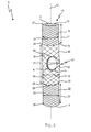
- Fig. 4 is an enlarged schematic drawing of an isolated exemplary stented valve member 40 which according to the invention is mounted onto the stent graft member 30.
- the stented valve member 40 comprises a stent element 41 and a valve 42, the valve 42 being mounted onto the stent element 41.
- the valve 42 comprises, in the exemplary embodiment shown in the figures, three leaflets or cusps 44.
- the valve can also be bi- or monocuspid, and may be created from human or animal pericardium or from native valves or veins or similar.
- the stent element 36 and the covering or graft 35 of the stent graft member 30 are designed, such, that upon attachment of the stented valve member 40 to the stent graft member 30, a blood flow via the attachment site is possible.
- the graft material or covering 35 of the stent graft member 30 has an opening in its circumference sized and fitted for the circumference of the stented valve member 40.
- the opening may be between two stent elements. Otherwise, e.g. when using a metal mesh as stent element for the stent graft element 30, the opening in the covering 35 may be formed in/by one or more meshes.
Landscapes
- Health & Medical Sciences (AREA)
- Engineering & Computer Science (AREA)
- Biomedical Technology (AREA)
- Cardiology (AREA)
- Life Sciences & Earth Sciences (AREA)
- Public Health (AREA)
- Oral & Maxillofacial Surgery (AREA)
- Heart & Thoracic Surgery (AREA)
- Veterinary Medicine (AREA)
- Animal Behavior & Ethology (AREA)
- General Health & Medical Sciences (AREA)
- Transplantation (AREA)
- Vascular Medicine (AREA)
- Surgery (AREA)
- Gastroenterology & Hepatology (AREA)
- Pulmonology (AREA)
- Nuclear Medicine, Radiotherapy & Molecular Imaging (AREA)
- Pathology (AREA)
- Medical Informatics (AREA)
- Molecular Biology (AREA)
- Prostheses (AREA)
- Materials For Medical Uses (AREA)
Abstract
Description
- The present invention relates to a device for implantation in the heart of a mammal, with a generally tubular shape, and having a longitudinal axis, a first end and a second end, and a lumen permitting blood flow there through.
- The present invention also relates to the use of such a device for treating tricuspid regurgitation in a mammal.
- The human heart is subdivided by septa into right and left halves, and a constriction subdivides each half of the organ into two cavities, the upper cavity being called the atrium, the lower the ventricle, respectively. Thus, the heart consists of four chambers, i.e., right and left atria, and right and left ventricles. Via the four valves of the human heart, i.e. the aortic, mitral, tricuspid and pulmonary valves, a one-way blood flow through the (healthy) heart is maintained. Thus, the four heart valves make sure that blood always flows freely in a forward direction and that there is no backward leakage.
- In the heart, blood flows from the right and left atria into the ventricles through the open tricuspid and mitral valves. When the ventricles are full, the tricuspid and mitral valves shut. This action, i.e. the closing of the tricuspid and the mitral valve, prevents blood from flowing backward into the atria while the ventricles contract. As the ventricles begin to contract, the pulmonic and aortic valves are forced open, thus pumping blood out of the ventricles: Blood present in the right ventricle passes through the open pulmonic valve into the pulmonary artery, and blood present in the left ventricle passes through the open aortic valve into the aorta where it is delivered to the rest of the body. When the ventricles finish contracting and begin to relax, the aortic and pulmonic valves shut. These valves prevent blood from flowing back into the ventricles.
- With each heartbeat, this pattern is repeated, causing blood to flow continuously to the heart, lungs, and body. Due to their vital function, diseased or malfunctioning heart valves are a major threat for a person's life.
- Several different kinds of valve disorders are known, such as stenosis, which occurs when a heart valve doesn't fully open due to stiff or fused leaflets preventing them from opening properly, or prolapse, where the valve flaps do not close smoothly or evenly but collapse backwards into the heart chamber they are supposed to be sealing off.
- Valve regurgitation (backward flow) is also common problem, and occurs when a heart valve doesn't close tightly, as a consequence of which the valve does not seal and blood leaks backwards across the valve. This condition - also called valvular insufficiency - reduces the heart's pumping efficiency: When the heart contracts blood is pumped forward in the proper direction but is also forced backwards through the damaged valve. As the leak worsens, the heart has to work harder to make up for the leaky valve and less blood may flow to the rest of the body. Depending on which valve is affected, the condition is called tricuspid regurgitation, pulmonary regurgitation, mitral regurgitation, or aortic regurgitation.
- While mitral insufficiency has - likely due to its higher occurrence - been subject matter of many treatment approaches in recent years, tricuspid insufficiency, or rather its treatment has gained only little attention over the past years. Tricuspid insufficiency may be asymptomatic, however, common symptoms are, e.g. hepatomegaly, edema and jugular distenosis. As a result of the failure of the tricuspid valve to close properly, with each heart beat some blood passes from the right ventricle to the right atrium, the opposite of the normal direction. Although congenital causes of tricuspid insufficiency exist, most cases are due to annulus dilation and dilation of the right ventricle, and this dilation leads to a derangement of the normal anatomy and mechanics of the tricuspid valve and the muscles governing its proper function. The result is incompetence of the tricuspid valve.
- However, isolated surgical tricuspid valve repair is seldom performed, and remains rather undertreated. Actually, most repairs are performed in the context with other planned cardiac surgeries.
- The main therapy of tricuspid insufficiency is treatment of underlying cause, which is why in most cases surgery is not indicated since the root problem lies with a dilated or damaged right ventricle. Medical therapy with diuretics is the mainstay of treatment. Unfortunately, this can lead to volume depletion and decreased cardiac output. Indeed, one must often accept a certain degree of symptomatic tricuspid insufficiency in order to prevent a decrease in cardiac output. Treatment with medicines to reduce cardiac afterload may also be of benefit but a similar risk of depressed cardiac output applies.
- Human heart valves may be replaced with mechanical valves, or with specially prepared heart valves from human or animal donors (known as bioprosthetic or tissue valves).
- Bioprosthetic valves are sometimes called tissue valves and made from specially treated natural ("biological") valves. These valves come from two sources: human donors and animals. Valves from animal sources (usually cows or pigs) are very similar to those found in the human heart.
- Surgical repair or replacement of the tricuspid valve carries a high operative mortality. When applying surgical means, tricuspid regurgitation is rectified either by replacement of the total valve with an replacement valve or by constriction of the valve ring with an annular remodeling ring, which involves rigid or flexible annular bands, which are intended to reduce annular size.
- Due to the high risk of surgical operations and due to the fact that in many cases a surgery is even impossible to perform, e.g. if the patient is inoperable or operable only at a too high surgical risk, transcatheter techniques and devices for tricuspid regurgitation treatment have recently been developed; however, only limited experimental transcatheter data is available.
- E.g.,
WO 2012/018599 A1 discloses a two valve caval stent for functional replacement of an incompetent tricuspid valve, which may be delivered by transcatheter placement. It comprises two stents connected by a bridge spanning the right atrium, and two valves anchored by the stents in the superior and inferior vena cavas. - Further,
WO 2004/093638 discloses a device and methods for treatment of tricuspid regurgitation, where a first and a second stented valve are implanted at the superior and inferior vena cava. The device is intended to permit blood flow towards the right atrium of a patient and prevent blood flow in the opposite direction. - Nevertheless, the currently available devices and their handling imply complicated deployment methods, making a smooth and fast valve replacement difficult to achieve.
- Thus, it is an object of the present invention to provide for a device that facilitates the treatment of tricuspid regurgitation and overcomes the drawbacks of the prior art devices and treatment methods.
- According to the invention, this and other objects is solved by a device for implantation in the heart of a mammal, with a generally tubular shape, and having a longitudinal axis, a first end and a second end, and a lumen permitting blood flow there through, wherein the device comprises: (i) a first tubular stent member, sized and configured for implantation within the superior vena cava, and having a length, a diameter, a first and a second end, (ii) a second tubular stent member, sized and configured for implantation within the inferior vena cava, and having a length, a diameter, a first and a second end, wherein the said second tubular stent member does not comprise a covering, (iii) a tubular stent graft member, having a length, a diameter, a first and a second stent graft member end, and comprising a covering being attached to a stent element, wherein the tubular stent graft member is fixedly assembled between the first and the second tubular stent members, such, that the second stent graft member end is attached to the first stent member's first end, and the first stent graft member end is attached to the second stent member's second end, wherein the stent graft member is sized and configured for implantation within the right atrium of the mammal's heart; and (iv) a stented valve member comprising a stent element and a valve, the valve being mounted on the stent element, wherein the stented valve member is fixedly mounted on the stent graft member, wherein the valve member is unidirectional, allowing blood to flow from the vena cava into the right atrium while blocking the blood flow in the opposite direction.
- With the device according to the invention and its use in the treatment of tricuspid insufficiency, it is possible to securely and conveniently replace the tricuspid valve's function and effectively support the heart's function. The device according to the invention spans a path through the heart from the vena cava superior to the vena cava inferior while simultaneously guaranteeing, by means of the fully functioning stented valve member, that the one-way blood flow from the right atrium to the right ventricle is maintained, and a backflow of the blood from the right ventricle into the right atrium can be prevented, thus effectively treating the tricuspid insufficiency.
- The device according to the invention is easy to handle and deploy since only once device needs to be deployed - contrary to the devices currently available which either necessitate the deployment of two separate valves in the vena cava superior and vena cava inferior, or which apply a replacement annular ring of the natural valve.
- Thus, with the device according to the invention, the overall deployment and valve replacement procedure, and, thus, the overall surgical operation, can be fast and easily accomplished.
- Presently, and as generally understood, a "stent" is to be understood and referred to as a cylindrical or tubular, radially-expandable metal frame or body and means any device or structure that adds rigidity, expansion force, or support to a prosthesis, while "stent graft" refers to a prosthesis comprising a stent and a graft material associated therewith that forms a fluid-tight or substantially fluid-tight lumen through at least a portion of its length. The cylindrical/tubular body of stents/stent grafts is inserted into the vessel/organ to be treated and is expanded or self-expandable and fixed or fixes itself at the appropriate site in order to keep open the lumen of the vessel/organ.
- The metal frame of the stent members and elements of the device according to the invention may be laser cut or woven or braided or knitted or comprise an otherwise interconnected metal mesh.
- Accordingly, a "graft" material is a cylindrical liner that may be disposed on the stent's interior, exterior or both. A wide variety of attachment mechanisms are available to join the stent and graft together, including but not limited to, sutures, adhesive bonding, heat welding, and ultrasonic welding. Presently, a "covering" also may designate or is designating a graft material attached to a stent member, which is why a "stent graft" is presently, and throughout the relevant field, also designated as "covered stent" or "covered stent graft".
- Stent grafts generally comprise, for example, a series of stent elements or, respectively, a wire framework made of a self-expanding material. In this context, stents are understood to be individual self-expanding elements. The self-expanding elements or, respectively, the wire framework are connected to each other by a textile or PTFE tube, called a graft sleeve, to form a functional unit and in this way, analogous to the stents described above, they form a tubular body that supports the vessel walls
- The stent elements of the stent graft may represent single metal rings forming a metal mesh, the rings meandering circumferentially and being disposed successively in the graft member's longitudinal axis/direction, wherein the metal rings have a Z-shaped profile with pointed arches pointing alternately toward the proximal end and distal end of the device.
- According to the invention, the tubular stent graft member located between the two, i.e. the first and second tubular stent members, forms a fluid-tight or substantially fluid-tight sealing, only permitting unidirectional blood flow towards the right ventricle via the stented valve member mounted thereupon.
- Also, and according to the invention, the second stent member does not comprise a covering or graft material, thus providing an anchor for the device in the vena cava inferior, whilst guaranteeing that blood flow into vessels which branch off the vena cava inferior are not blocked. The first stent member, on the other hand may be covered or not, and is, according to a preferred embodiment, not covered by a graft material/covering. Accordingly, the first stent member provides for anchoring means of the device within the vena cava superior.
- The stent/stent member according to the invention can be made of or comprise any suitable material, including but not limited to biocompatible metals, implantable quality stainless steel wires, nickel and titanium alloys, in particular nitinol, and biocompatible plastics attached to a graft.
- Any suitable fluid tight or substantially fluid-tight graft material can be used. In a preferred embodiment, the graft material is a biocompatible fabric, including but not limited to woven, knitted or otherwise fabricated material, such as polyester, such as polyethylene terephthalate, fluorinated polymers, such as polytetrafluoroethylene (PTFE), expanded PTFE (ePTFE), polyvinylidene fluoride, polysiloxane, including polydimethyl siloxane, polyurethanes, including polyetherurethanes, polylactide, polyglycolide and copolymers thereof.
- Also, materials that are not inherently biocompatible may be used when previously subjected to surface modifications in order to render the materials biocompatible.
- Further, biomaterial as mammal (i.e. bovine, porcine) derived pericardium or submucosa of small intestine (SIS) or any other cross linked bio-material tissue suitable to be used as a graft material may be employed.
- According to the invention, the (covered) stent graft member can be made of any suitable material, including but not limited to polytetrafluoroethylene (ePTFE) lined nickel-titanium alloy (nitinol) stent.
- The components of the device, i.e. the first and second stent members and the stent graft member comprising the stented valve member can be variously sized (i.e.: length, diameter, etc.) as suitable for an intended use and as depending on the respective condition of the patient's heart, and are preferably larger in diameter than the inner vessel diameter the members of the device are to be placed in.
- It is to be understood that the covering and/or the stent element of the stent graft member at the site where the stented valve member is attached to the stent graft member allow for a fluid path into and out of the valve in the direction towards the atrium. This can be accomplished by means of an opening in the covering, sized and fitted for the stented valve member attached thereto, and/or meshes of the stent graft's stent element.
- According to another aspect of the device of the invention, the device further comprises visualization elements, in particular radio-opaque markers, wherein the visualization elements are attached to the device at one or more of the following elements of the device: at the site where the stent graft member's first end is attached to the second stent member's second end, at the site where the stent graft member's second end is attached to the first stent member's first end, and/or at the fixation site of the stented valve member to the stent graft member.
- Presently, "visualization elements" shall mean any suitable aid attached or otherwise provided on the device facilitating the accurate placement of the device. According to one aspect of the invention, those visualization elements are radiopaque markers comprising or consisting of any suitable material, such as, e.g., gold, tantalum, platinum.
- The visualization elements may, e.g., take the form of gold bands or singular elements at the respective preferred locations of the device, or represent directional elements or markers, e.g. in the shape of a letter, such as "E" or "S" or "J" or "L" or any other suitable letter or form for indicating direction and orientation of the device.
- The visualization elements are, in one embodiment, arranged over the circumference at the site where the stent graft element and the tubular stent elements are attached to one another, and/or at the site where the stented valve member is attached to the stent graft element.
- According to another aspect of the invention, at least one of the following, the first stent member, the second stent member, the stent element of the stent graft member, and/or the stent element of the stented valve member is/are self-expanding, wherein the device is configured, such, that it is convertible from a compressed state for introducing the device into a heart of a mammal to an expanded state within the heart.
- Accordingly, the stent elements of the device are preferably self-expanding, although the device - or rather its stent/stent graft members/elements, may also be, e.g., balloon-expandable. The stent members allow for radial force fixation within the vena cava.
- According to a preferred embodiment, the device of the invention, along its longitudinal axis, varies in its diameter. With this embodiment, the different diameters and conditions of the vessels, in particular the vena cava can be respected.
- Further, in a preferred embodiment, the first stent member's diameter is, in the expanded state of the device, smaller than the second stent member's diameter.
- In this embodiment, i.e. where the first stent member has - in its expanded state - a smaller diameter than the second stent member, the diameters are reflecting the larger diameter of the vena cava inferior as compared to the diameter of the vena cava superior. Thus, a secure fixation of the device in the vena cava can be achieved.
- In another embodiment of the device according to the invention, the diameter of each, the first stent member, the second stent member and/or the stent graft member, vary along the respective lengths for the members.
- With this embodiment, an even finer adjustment of the device to the respective vessel conditions and forms can be guaranteed.
- According to one aspect of the invention, in the device as claimed and disclosed, the valve is a biological valve comprising one, two or three leaflets, preferably three.
- The healthy human tricuspid valve comprises three leaflets, or cusps, named after their positions: anterior, posterior and septal. Thus, according to one aspect, the valve of the stented valve mounted on the stent graft member also comprises three leaflets, and thus, represents a tricuspid valve, whilst also a valve having only two leaflets and, having, thus, a "bicuspid" architecture, or with even one leaflet, i.e. a monocuspid valve, can be used with the device according to the invention. Such valves can be created from human or animal donors. They can be created, e.g., from pericardium of human or any mammal, or from native leaflets from the heart or veins, or from any other biological material suitable for the intended purpose. Generally speaking, such valves are also called biological or tissue valves - as contrary to mechanical valves.
- Accordingly, in a preferred embodiment, the biological valve comprises or consists of a material that is selected from animal pericardium, in particular porcine, bovine, equine pericardium, or from native leaflets from human heart or veins.
- The invention also relates to the use of the device according to the invention for treating tricuspid regurgitation in a mammal, as well as to a method for treating tricuspid regurgitation in a mammal, comprising the step of delivering and/or implanting a device according to the invention to a position within the heart of a patient in need thereof in order to replace or support the native tricuspid valve of said patient.
- The device according to the invention can be either surgically implanted or delivered by transcatheter methods. In the latter case, i.e. with a transcatheter method, the device according to the invention is loaded onto a suitable deployment catheter, there being compressed by a retractable sheath or tube. The deployment catheter is inserted into the heart of a patient whose tricuspid valve needs replacement or support. The deployment catheter having the device according to the invention loaded thereon in a compressed state, is advanced via the jugular vein into the vena cava superior into the right atrium and into the vena cava inferior, as far as the second tubular stent member is placed into the vena cava inferior, the stent graft member within the right atrium and the first tubular stent member into the vena cava superior. Alternatively, the deployment catheter having the device according to the invention loaded thereon in a compressed state can be advanced via the femoral vein into the vena cava inferior into the right atrium and into the vena cava superior, as far as the first tubular stent member is placed into the vena cava superior, the stent graft member within the right atrium and the second tubular stent member into the vena cava inferior. Correct placement can be monitored via the visualization elements.
- Upon correct placement, the sheath or the otherwise compressing means is retracted to stepwise release the device according to the invention, upon which action the stent members of the device can expand and fixate the device in the vena cava superior and inferior, respectively.
- Since also the stent graft member is released, the stented valve element mounted thereon can operate as soon as the compressing means are retracted.
- Further advantages and features of the invention are set forth in the following description and in the attached figures.
- It will be understood that the aforementioned features and the features still to be explained below can be used not only in the respectively specified combination but also in other combinations or on their own, without departing from the scope of the present invention.
- The aforementioned features of the invention and the features still to be explained below are shown in the figures, in which:
- Fig. 1
- shows a schematic drawing of a human heart;
- Fig. 2
- shows a schematic drawing of an exemplary embodiment of the device according to the invention placed in the correct position in the heart of
fig. 1 ; - Fig. 3
- a schematic drawing of the embodiment as shown in
Fig. 2 , outside the heart and in enlarged detail; and - Fig. 4
- an enlarged schematic drawing of an isolated exemplary stented valve member as present in a device according to the invention.
- In
Fig. 1 , ahuman heart 50 is depicted, having aright atrium 54, aright ventricle 55, aleft atrium 56 and aleft ventricle 57. Also depicted infig. 1 is a portion of the vena cava superior 52, entering theheart 50 via theright atrium 54, and a portion of the vena cava inferior 53. - In more detail, the
superior vena cava 52 returns the blood from the upper half of the body, and opens into the upper and back part of theright atrium 54, the direction of itsorifice 52a being downward and forward. Itsorifice 52a has no valve. - The
inferior vena cava 53, which has a larger diameter than thesuperior vena cava 52, returns the blood from the lower half of the body, and opens into the lowest part of theright atrium 54, itsorifice 53a being directed upward and backward, and guarded by a rudimentary valve, the valve of the inferior vena cava (Eustachian valve, not shown). - The
right ventricle 55 has a triangular in form, and extends from theright atrium 54 to near the apex 59 of theheart 50. - The right atrioventricular orifice (not depicted in
fig. 1 ) is the large oval aperture of communication between theright atrium 54 andventricle 55, and is guarded by thetricuspid valve 60. - The
opening 61 of thepulmonary artery 62 is circular in form, and is placed above and to the left of the atrioventricular opening; it is guarded by thepulmonary valves 63. - The
tricuspid valve 60 consists of three about triangular cusps or segments orleaflets 64, the anterior, posterior and medial or septal cusp. Their bases are attached to a fibrous ring (not depicted infig. 1 ) surrounding the atrioventricular orifice and are also joined to each other so as to form a continuous annular membrane. Their atrial surfaces are directed toward the blood current from theatrium 54, while their ventricular surfaces are directed toward the wall of theventricle 55; together with the apices and margins of the cusps, they give attachment for the chordae tendineae (not depicted infig. 1 ). - As discussed above, the function of the tricuspid valve is to prevent back flow of blood into the
right atrium 54;arrows right atrium 54. - The
left atrium 56 is smaller than theright atrium 54. Theleft ventricle 57 is longer and more conical in shape than theright ventricle 55. The left atrioventricular opening (mitral orifice, not depicted infig. 1 ) is placed to the left of theaortic orifice 65, and is guarded by the bicuspid ormitral valve 66. - The
aortic opening 65 is a circular aperture, in front and to the right of the atrioventricular opening, and its orifice is guarded by the threeaortic valves 67.Reference number 68 designates the aorta. - Tricuspid regurgitation is not uncommon in the
tricuspid valve 60, and means that blood from theright ventricle 55 flows back into theright atrium 54 upon contraction of theright ventricle 55 due to thetricuspid valve 60 not properly closing. - With the device according to the invention, tricuspid regurgitation is to be treated, and placement of an exemplary embodiment of the device according to the invention is depicted in the attached
fig. 2 . -
Fig. 2 shows the schematic drawing of the heart as already depicted infig. 1 . For better understanding,fig. 2 does not include all of the reference numbers as designated infig. 1 , but is meant to show the same features of thehuman heart 50. - As can be seen in
Fig. 2 , thedevice 10 according to the invention is placed in the expanded state in thehuman heart 50. The device as such is shown in more detail infig. 3 , and in the following it will be made reference to both,fig. 2 and3 ; for the sake of better understanding, not all of the features of the device designated infig. 3 are designated infig. 2 , however, the features are nevertheless the same. -
Device 10 comprises a generaltubular shape 11, and has alongitudinal axis 12, afirst end 13 and asecond end 14, with alumen 15 extending in between and permitting blood flow there through. - The
device 10 comprises a firsttubular stent member 16, asecond stent member 22, and astent graft member 30 placed in between the first and second tubular stent member. The firsttubular stent member 16 has alength 17, adiameter 18, and a first and asecond end Length 17 anddiameter 18 of the firsttubular stent member 16 are such that thestent member 16 can securely anchor the device's 10first end 13 within the vena cava superior 52. - Also, the
second stent member 22 has alength 23, adiameter 24, a first and asecond end Length 23 anddiameter 24 of the secondtubular stent member 22 are such that thestent member 22 securely anchors the device'ssecond end 14 within the vena cava inferior 53. - The
stent graft member 30 has alength 31, adiameter 32, a first and asecond end graft 35 which is attached to or lines astent element 36, whichstent element 36 represents a tubular metal frame. The length of thestent graft member 30 is designed such, that is lies within theright atrium 54 of theheart 50 of a patient who is to be treated. The covering orgraft 35 is made of or comprises a biocompatible material and provides for a leak-tight or substantially leak-tight closure of the tubular device in theright atrium 54. -
Stent graft member 30 further comprises a stentedvalve member 40, mounted or attached tostent graft member 30.Stented valve member 40 comprises astent element 31 and avalve 42, thevalve 42 being mounted on thestent element 41.Stented valve member 40 represents a unidirectional valve, allowing blood to flow from thevena cava 52/53 into theright atrium 54 while blocking the blood flow in the opposite direction, i.e. blocks flow from theright ventricle 55 into theatrium 54. The stentedvalve member 40 will be described in more detail with reference tofig. 4 below. - The first and
second stent members stent graft member 30 are fixedly connected with each other as follows and form, thus, a tubular one-piece device: - At its
first end 19, thefirst stent element 16 is attached to the stent graft member's 22second end 34. The stent graft member's 30first end 33 is attached to thesecond end 26 of thesecond stent member 22. -
Device 10 further comprisesvisualization elements 80, which, in the embodiment shown infigs. 2 and3 , are placed at the site where the stent graft member'sfirst end 33 is attached to the second stent member's 22second end 26, at the site where the stent graft member'ssecond end 34 is attached to the first stent member's 16first end 19, and/or at afixation site 43 of the stentedvalve member 40 to thestent graft member 30. Preferably, and as shown in the figures, thevisualization elements 80 are placed circumferentially around thetubular form 11 at the respective sites. -
Fig. 4 is an enlarged schematic drawing of an isolated exemplary stentedvalve member 40 which according to the invention is mounted onto thestent graft member 30. - As can be seen in
fig. 4 in more detail, the stentedvalve member 40 comprises astent element 41 and avalve 42, thevalve 42 being mounted onto thestent element 41. Thevalve 42 comprises, in the exemplary embodiment shown in the figures, three leaflets or cusps 44. - As described in the general section, the valve can also be bi- or monocuspid, and may be created from human or animal pericardium or from native valves or veins or similar.
- It is to be understood that the
stent element 36 and the covering orgraft 35 of thestent graft member 30 are designed, such, that upon attachment of the stentedvalve member 40 to thestent graft member 30, a blood flow via the attachment site is possible. This means that the graft material or covering 35 of thestent graft member 30 has an opening in its circumference sized and fitted for the circumference of the stentedvalve member 40. When using singular stent elements only connected to each other via the covering 35, the opening may be between two stent elements. Otherwise, e.g. when using a metal mesh as stent element for thestent graft element 30, the opening in the covering 35 may be formed in/by one or more meshes.
Claims (12)
- Device (10) for implantation in the heart (50) of a mammal, with a generally tubular shape (11), and having a longitudinal axis (12), a first end (13) and a second end (14), and a lumen (15) permitting blood flow there through, wherein the device (10) comprises- a first tubular stent member (16), sized and configured for implantation within the superior vena cava (52), and having a length (17), a diameter (18), a first (19) and a second end (20),- a second tubular stent member (22), sized and configured for implantation within the inferior vena cava (53), and having a length (23), a diameter (24), a first (25) and a second end (26), wherein the said second tubular stent member (22) does not comprise a covering,- a tubular stent graft member (30), having a length (31), a diameter (32), a first (33) and a second stent graft member end (34), and comprising a covering (35) being attached to a stent element (36), wherein the tubular stent graft member (30) is fixedly assembled between the first (16) and the second (22) tubular stent members, such, that the second stent graft member end (34) is attached to the first stent member's first end (19), and the first stent graft member end (33) is attached to the second stent member's second end (26), wherein the stent graft member (30) is sized and configured for implantation within the right atrium (54) of the mammal's heart (50); and- a stented valve member (40) comprising a stent element (41) and a valve (42), the valve (42) being mounted on the stent element (41), wherein the stented valve member (40) is fixedly mounted on the stent graft member (30), wherein the valve member (40) is unidirectional, allowing blood to flow from the vena cava into the right atrium while blocking the blood flow in the opposite direction.
- The device (10) of claim 1, wherein also said first stent member (16) does not comprise a covering.
- The device (10) of claim 1 or 2, further comprising visualization elements (80), preferably radio-opaque markers, wherein the visualization elements (80) are attached to the device (10) at one or more of the following sites of the device (10): at the site where the stent graft member's (30) first end (33) is attached to the second stent member's (22) second end (26), at the site where the stent graft member's (30) second end (34) is attached to the first stent member's (16) first end (19), and/or at the fixation site (43) of the stented valve member (40) to the stent graft member (30).
- The device (10) of any of the preceding claims, wherein at least one of the first stent member (16), the second stent member (22), the stent element (36) of the stent graft member (30), and/or the stent element (41) of the stented valve member (40) is/are self-expanding, and wherein the device (10) is configured, such, that it is convertible from a compressed state for introducing the device into a heart (50) of a mammal to an expanded state within the heart (50).
- The device (10) of any of the preceding claims, wherein the device (10), along its longitudinal axis (12), varies in its diameter.
- The device (10) of any of the preceding claims, wherein the first stent member's (16) diameter (18) is, in the expanded state of the device (10), smaller than the second stent member's (22) diameter (24).
- The device (10) of any of the preceding claims, wherein the diameter (18; 24; 32) of each, the first stent member (16), the second stent member (22) and/or the stent graft member (30), vary along the respective lengths (17; 23, 31) for the members (16, 22, 30).
- The device (10) of any of the preceding claims, wherein the valve (42) is a biological valve comprising one, two or three leaflets (44).
- The device (10) of any of the preceding claims, wherein the biological valve comprises or consists of a material that is selected from animal pericardium, in particular porcine, bovine, equine pericardium, or from native leaflets from human heart or veins.
- The device (10) of any of the preceding claims, wherein the covering (35) of the stent graft member (30) comprises or consists of a material selected from at least one of the following: polyester, polytetrafluoroethylene (PTFE), expanded PTFE (ePTFE), polyvinylidene fluoride, polysiloxane, polyurethane, polylactide, polyglycolide and copolymers thereof.
- The device (10) of any of the preceding claims, wherein at least one of the first stent member (16), the second stent member (22), the stent element (36) of the stent graft member (30), and/or the stent element (41) of the stented valve member (40) is/are woven, braided or laser-cut.
- Use of the device (10) of any of the preceding claims for treating tricuspid regurgitation in a mammal.
Priority Applications (6)
| Application Number | Priority Date | Filing Date | Title |
|---|---|---|---|
| ES14163731.4T ES2635438T3 (en) | 2014-04-07 | 2014-04-07 | Device for implantation in the heart of a mammal |
| PL14163731T PL2929860T3 (en) | 2014-04-07 | 2014-04-07 | Device for implantation in the heart of a mammal |
| EP14163731.4A EP2929860B1 (en) | 2014-04-07 | 2014-04-07 | Device for implantation in the heart of a mammal |
| JP2015037703A JP6560507B2 (en) | 2014-04-07 | 2015-02-27 | Device for implantation in the heart of a mammal |
| CN201510154584.2A CN104970901B (en) | 2014-04-07 | 2015-04-02 | Equipment for being implanted into the heart of mammal |
| US14/678,376 US10028821B2 (en) | 2014-04-07 | 2015-04-03 | Device for implantation in the heart of a mammal |
Applications Claiming Priority (1)
| Application Number | Priority Date | Filing Date | Title |
|---|---|---|---|
| EP14163731.4A EP2929860B1 (en) | 2014-04-07 | 2014-04-07 | Device for implantation in the heart of a mammal |
Publications (2)
| Publication Number | Publication Date |
|---|---|
| EP2929860A1 true EP2929860A1 (en) | 2015-10-14 |
| EP2929860B1 EP2929860B1 (en) | 2017-06-28 |
Family
ID=50473090
Family Applications (1)
| Application Number | Title | Priority Date | Filing Date |
|---|---|---|---|
| EP14163731.4A Active EP2929860B1 (en) | 2014-04-07 | 2014-04-07 | Device for implantation in the heart of a mammal |
Country Status (6)
| Country | Link |
|---|---|
| US (1) | US10028821B2 (en) |
| EP (1) | EP2929860B1 (en) |
| JP (1) | JP6560507B2 (en) |
| CN (1) | CN104970901B (en) |
| ES (1) | ES2635438T3 (en) |
| PL (1) | PL2929860T3 (en) |
Cited By (6)
| Publication number | Priority date | Publication date | Assignee | Title |
|---|---|---|---|---|
| WO2017105986A1 (en) * | 2015-12-14 | 2017-06-22 | The Cleveland Clinic Foundation | Apparatus for repairing the function of a diseased valve and method for making the apparatus |
| US10660749B2 (en) | 2014-07-16 | 2020-05-26 | Nvt Ag | Heart valve prosthesis for percutaneous replacement of a tricuspid valve, and system comprising a heart valve prosthesis of said type |
| WO2021058512A1 (en) * | 2019-09-26 | 2021-04-01 | Biotronik Ag | Artificial cardiac valve |
| EP3801384A4 (en) * | 2018-06-08 | 2022-04-13 | Innoventric Ltd. | Systems, methods and devices for treating tricuspid insufficiency |
| US11723766B2 (en) | 2016-11-15 | 2023-08-15 | Envveno Medical Corporation | Implantable vein frame |
| US11998462B2 (en) | 2020-12-08 | 2024-06-04 | Innoventric Ltd. | Systems, methods and devices for treating tricuspid insufficiency |
Families Citing this family (48)
| Publication number | Priority date | Publication date | Assignee | Title |
|---|---|---|---|---|
| US8579964B2 (en) | 2010-05-05 | 2013-11-12 | Neovasc Inc. | Transcatheter mitral valve prosthesis |
| US9308087B2 (en) | 2011-04-28 | 2016-04-12 | Neovasc Tiara Inc. | Sequentially deployed transcatheter mitral valve prosthesis |
| US9554897B2 (en) | 2011-04-28 | 2017-01-31 | Neovasc Tiara Inc. | Methods and apparatus for engaging a valve prosthesis with tissue |
| US9345573B2 (en) | 2012-05-30 | 2016-05-24 | Neovasc Tiara Inc. | Methods and apparatus for loading a prosthesis onto a delivery system |
| US9572665B2 (en) | 2013-04-04 | 2017-02-21 | Neovasc Tiara Inc. | Methods and apparatus for delivering a prosthetic valve to a beating heart |
| CN108882981B (en) | 2016-01-29 | 2021-08-10 | 内奥瓦斯克迪亚拉公司 | Prosthetic valve for preventing outflow obstruction |
| CA3013861A1 (en) | 2016-02-08 | 2017-08-17 | Innoventric Ltd. | Treatment of tricuspid insufficiency |
| US10130465B2 (en) * | 2016-02-23 | 2018-11-20 | Abbott Cardiovascular Systems Inc. | Bifurcated tubular graft for treating tricuspid regurgitation |
| CN107212947A (en) * | 2016-03-22 | 2017-09-29 | 刘健 | The vena cave of tricuspid insufficiency functional appliance-atrium dextrum overlay film frame |
| CN106073945B (en) * | 2016-06-27 | 2018-10-12 | 复旦大学附属中山医院 | A kind of dystopy implantation valve bracket system for treating tricuspid regurgitation |
| AU2017361296B2 (en) | 2016-11-21 | 2022-09-29 | Neovasc Tiara Inc. | Methods and systems for rapid retraction of a transcatheter heart valve delivery system |
| US10653523B2 (en) | 2017-01-19 | 2020-05-19 | 4C Medical Technologies, Inc. | Systems, methods and devices for delivery systems, methods and devices for implanting prosthetic heart valves |
| US10561495B2 (en) | 2017-01-24 | 2020-02-18 | 4C Medical Technologies, Inc. | Systems, methods and devices for two-step delivery and implantation of prosthetic heart valve |
| CN111263622A (en) | 2017-08-25 | 2020-06-09 | 内奥瓦斯克迪亚拉公司 | Sequentially deployed transcatheter mitral valve prosthesis |
| DE102017121143A1 (en) * | 2017-09-13 | 2019-03-14 | Universitätsklinikum Hamburg-Eppendorf (UKE) | Implantable valve prosthesis |
| WO2019195860A2 (en) | 2018-04-04 | 2019-10-10 | Vdyne, Llc | Devices and methods for anchoring transcatheter heart valve |
| US20210177426A1 (en) * | 2018-05-12 | 2021-06-17 | Venacore Inc. | Controlling rate of blood flow to right atrium |
| US10779937B2 (en) | 2018-06-22 | 2020-09-22 | Vdyne, Inc. | Transcatheter heart valve with plication window and tissue anchors |
| US11857441B2 (en) | 2018-09-04 | 2024-01-02 | 4C Medical Technologies, Inc. | Stent loading device |
| US11344413B2 (en) | 2018-09-20 | 2022-05-31 | Vdyne, Inc. | Transcatheter deliverable prosthetic heart valves and methods of delivery |
| US11071627B2 (en) | 2018-10-18 | 2021-07-27 | Vdyne, Inc. | Orthogonally delivered transcatheter heart valve frame for valve in valve prosthesis |
| US11278437B2 (en) | 2018-12-08 | 2022-03-22 | Vdyne, Inc. | Compression capable annular frames for side delivery of transcatheter heart valve replacement |
| US10321995B1 (en) | 2018-09-20 | 2019-06-18 | Vdyne, Llc | Orthogonally delivered transcatheter heart valve replacement |
| US10595994B1 (en) | 2018-09-20 | 2020-03-24 | Vdyne, Llc | Side-delivered transcatheter heart valve replacement |
| US11109969B2 (en) | 2018-10-22 | 2021-09-07 | Vdyne, Inc. | Guidewire delivery of transcatheter heart valve |
| CA3118599A1 (en) | 2018-11-08 | 2020-05-14 | Neovasc Tiara Inc. | Ventricular deployment of a transcatheter mitral valve prosthesis |
| US10653522B1 (en) | 2018-12-20 | 2020-05-19 | Vdyne, Inc. | Proximal tab for side-delivered transcatheter heart valve prosthesis |
| US11253359B2 (en) | 2018-12-20 | 2022-02-22 | Vdyne, Inc. | Proximal tab for side-delivered transcatheter heart valves and methods of delivery |
| US11273032B2 (en) | 2019-01-26 | 2022-03-15 | Vdyne, Inc. | Collapsible inner flow control component for side-deliverable transcatheter heart valve prosthesis |
| US11185409B2 (en) | 2019-01-26 | 2021-11-30 | Vdyne, Inc. | Collapsible inner flow control component for side-delivered transcatheter heart valve prosthesis |
| EP3934583B1 (en) | 2019-03-05 | 2023-12-13 | Vdyne, Inc. | Tricuspid regurgitation control devices for orthogonal transcatheter heart valve prosthesis |
| US11076956B2 (en) | 2019-03-14 | 2021-08-03 | Vdyne, Inc. | Proximal, distal, and anterior anchoring tabs for side-delivered transcatheter mitral valve prosthesis |
| US10631983B1 (en) | 2019-03-14 | 2020-04-28 | Vdyne, Inc. | Distal subannular anchoring tab for side-delivered transcatheter valve prosthesis |
| US10758346B1 (en) | 2019-03-14 | 2020-09-01 | Vdyne, Inc. | A2 clip for side-delivered transcatheter mitral valve prosthesis |
| US11173027B2 (en) | 2019-03-14 | 2021-11-16 | Vdyne, Inc. | Side-deliverable transcatheter prosthetic valves and methods for delivering and anchoring the same |
| AU2020256195B2 (en) | 2019-04-01 | 2022-10-13 | Neovasc Tiara Inc. | Controllably deployable prosthetic valve |
| US11491006B2 (en) | 2019-04-10 | 2022-11-08 | Neovasc Tiara Inc. | Prosthetic valve with natural blood flow |
| EP3965701A4 (en) | 2019-05-04 | 2023-02-15 | Vdyne, Inc. | Cinch device and method for deployment of a side-delivered prosthetic heart valve in a native annulus |
| US11779742B2 (en) | 2019-05-20 | 2023-10-10 | Neovasc Tiara Inc. | Introducer with hemostasis mechanism |
| US11311376B2 (en) | 2019-06-20 | 2022-04-26 | Neovase Tiara Inc. | Low profile prosthetic mitral valve |
| WO2020264136A1 (en) * | 2019-06-28 | 2020-12-30 | University Of Pittsburgh - Of The Commonwealth System Of Higher Education | Valved stent for the treatment of tricuspid regurgitation |
| EP4017442A4 (en) | 2019-08-20 | 2023-07-26 | Vdyne, Inc. | Delivery and retrieval devices and methods for side-deliverable transcatheter prosthetic valves |
| EP4021445A4 (en) | 2019-08-26 | 2023-09-20 | Vdyne, Inc. | Side-deliverable transcatheter prosthetic valves and methods for delivering and anchoring the same |
| US20240091034A1 (en) * | 2019-10-11 | 2024-03-21 | Institute Of Advanced Medical Research And Innovations Forum | Device and method for closure of sinus venosus atrial septal defects |
| US11234813B2 (en) | 2020-01-17 | 2022-02-01 | Vdyne, Inc. | Ventricular stability elements for side-deliverable prosthetic heart valves and methods of delivery |
| US11931253B2 (en) | 2020-01-31 | 2024-03-19 | 4C Medical Technologies, Inc. | Prosthetic heart valve delivery system: ball-slide attachment |
| US11992403B2 (en) | 2020-03-06 | 2024-05-28 | 4C Medical Technologies, Inc. | Devices, systems and methods for improving recapture of prosthetic heart valve device with stent frame having valve support with inwardly stent cells |
| US11759460B2 (en) | 2020-08-14 | 2023-09-19 | Devie Medical Gmbh | Method of local antibiotic treatment of infective endocarditis |
Citations (5)
| Publication number | Priority date | Publication date | Assignee | Title |
|---|---|---|---|---|
| WO2004093638A2 (en) | 2003-04-17 | 2004-11-04 | Mccarthy Patrick M | Methods for reduction of pressure effects of cardiac tricuspid valve regurgitation |
| US20070244494A1 (en) * | 2006-04-18 | 2007-10-18 | Downing Stephen W | Methods and devices for treating atrial septal defects |
| WO2007121028A2 (en) * | 2006-03-23 | 2007-10-25 | The Trustees Of Columbia University | Method of inhibiting disruption of the healing process in a physically modified stomach |
| WO2012018599A1 (en) | 2010-08-03 | 2012-02-09 | Cook Medical Technologies Llc | Two valve caval stent for functional replacement of incompetent tricuspid valve |
| EP2522306A1 (en) * | 2011-05-09 | 2012-11-14 | Cook Medical Technologies LLC | Paraplegia prevention valve for stent grafts |
Family Cites Families (11)
| Publication number | Priority date | Publication date | Assignee | Title |
|---|---|---|---|---|
| JP2825452B2 (en) * | 1994-04-25 | 1998-11-18 | アドヴァンスド カーディオヴァスキュラー システムズ インコーポレーテッド | Radiopak stent marker |
| CA2163824C (en) * | 1994-11-28 | 2000-06-20 | Richard J. Saunders | Method and apparatus for direct laser cutting of metal stents |
| EP0850607A1 (en) * | 1996-12-31 | 1998-07-01 | Cordis Corporation | Valve prosthesis for implantation in body channels |
| US20020198585A1 (en) * | 1999-10-05 | 2002-12-26 | Willem Wisselink | System and method for edoluminal grafting of bifurcated or branched vessels |
| US7083822B2 (en) * | 2002-04-26 | 2006-08-01 | Medtronic Vascular, Inc. | Overlapping coated stents |
| US7485141B2 (en) * | 2002-05-10 | 2009-02-03 | Cordis Corporation | Method of placing a tubular membrane on a structural frame |
| US7244444B2 (en) * | 2004-03-31 | 2007-07-17 | Cook Incorporated | Graft material, stent graft and method |
| CA2609022C (en) * | 2005-05-20 | 2010-07-20 | The Cleveland Clinic Foundation | Apparatus and methods for repairing the function of a diseased valve and method for making same |
| EP2004095B1 (en) * | 2006-03-28 | 2019-06-12 | Medtronic, Inc. | Prosthetic cardiac valve formed from pericardium material and methods of making same |
| WO2007124053A1 (en) * | 2006-04-19 | 2007-11-01 | William A. Cook Australia Pty. Ltd. | Twin bifurcated stent graft |
| US8475525B2 (en) * | 2010-01-22 | 2013-07-02 | 4Tech Inc. | Tricuspid valve repair using tension |
-
2014
- 2014-04-07 EP EP14163731.4A patent/EP2929860B1/en active Active
- 2014-04-07 PL PL14163731T patent/PL2929860T3/en unknown
- 2014-04-07 ES ES14163731.4T patent/ES2635438T3/en active Active
-
2015
- 2015-02-27 JP JP2015037703A patent/JP6560507B2/en active Active
- 2015-04-02 CN CN201510154584.2A patent/CN104970901B/en active Active
- 2015-04-03 US US14/678,376 patent/US10028821B2/en active Active
Patent Citations (5)
| Publication number | Priority date | Publication date | Assignee | Title |
|---|---|---|---|---|
| WO2004093638A2 (en) | 2003-04-17 | 2004-11-04 | Mccarthy Patrick M | Methods for reduction of pressure effects of cardiac tricuspid valve regurgitation |
| WO2007121028A2 (en) * | 2006-03-23 | 2007-10-25 | The Trustees Of Columbia University | Method of inhibiting disruption of the healing process in a physically modified stomach |
| US20070244494A1 (en) * | 2006-04-18 | 2007-10-18 | Downing Stephen W | Methods and devices for treating atrial septal defects |
| WO2012018599A1 (en) | 2010-08-03 | 2012-02-09 | Cook Medical Technologies Llc | Two valve caval stent for functional replacement of incompetent tricuspid valve |
| EP2522306A1 (en) * | 2011-05-09 | 2012-11-14 | Cook Medical Technologies LLC | Paraplegia prevention valve for stent grafts |
Cited By (9)
| Publication number | Priority date | Publication date | Assignee | Title |
|---|---|---|---|---|
| US10660749B2 (en) | 2014-07-16 | 2020-05-26 | Nvt Ag | Heart valve prosthesis for percutaneous replacement of a tricuspid valve, and system comprising a heart valve prosthesis of said type |
| EP3169276B1 (en) * | 2014-07-16 | 2020-10-14 | Medira Ag | Heart valve prosthesis for percutaneous replacement of a tricuspid valve, and system comprising a heart valve prosthesis of said type |
| WO2017105986A1 (en) * | 2015-12-14 | 2017-06-22 | The Cleveland Clinic Foundation | Apparatus for repairing the function of a diseased valve and method for making the apparatus |
| US10335272B2 (en) | 2015-12-14 | 2019-07-02 | The Cleveland Clinic Foundation | Apparatus and method for repairing the function of a diseased valve |
| US11723766B2 (en) | 2016-11-15 | 2023-08-15 | Envveno Medical Corporation | Implantable vein frame |
| US11872126B2 (en) | 2016-11-15 | 2024-01-16 | Envveno Medical Corporation | Implantable vein frame |
| EP3801384A4 (en) * | 2018-06-08 | 2022-04-13 | Innoventric Ltd. | Systems, methods and devices for treating tricuspid insufficiency |
| WO2021058512A1 (en) * | 2019-09-26 | 2021-04-01 | Biotronik Ag | Artificial cardiac valve |
| US11998462B2 (en) | 2020-12-08 | 2024-06-04 | Innoventric Ltd. | Systems, methods and devices for treating tricuspid insufficiency |
Also Published As
| Publication number | Publication date |
|---|---|
| EP2929860B1 (en) | 2017-06-28 |
| JP2015198914A (en) | 2015-11-12 |
| ES2635438T3 (en) | 2017-10-03 |
| US10028821B2 (en) | 2018-07-24 |
| PL2929860T3 (en) | 2018-01-31 |
| CN104970901B (en) | 2018-10-02 |
| CN104970901A (en) | 2015-10-14 |
| JP6560507B2 (en) | 2019-08-14 |
| US20150282958A1 (en) | 2015-10-08 |
Similar Documents
| Publication | Publication Date | Title |
|---|---|---|
| US10028821B2 (en) | Device for implantation in the heart of a mammal | |
| US9839517B2 (en) | Implantable device for treating mitral valve regurgitation | |
| US10888424B2 (en) | Prosthetic mitral valve coaptation enhancement device | |
| US11007054B2 (en) | Subannular sealing for paravalvular leak protection | |
| JP6858337B2 (en) | Artificial heart valve system and delivery system for the system | |
| CN108366856B (en) | Delivery system for transcatheter implantation of a heart valve prosthesis | |
| EP3226809B1 (en) | Segmented transcatheter valve prosthesis having an unsupported valve segment | |
| US10321993B2 (en) | Self-expanding heart valves for coronary perfusion and sealing | |
| US20180325666A1 (en) | Method and Design for a Mitral Regurgitation Treatment Device | |
| US10213307B2 (en) | Transcatheter valve prosthesis having an external skirt for sealing and preventing paravalvular leakage | |
| JP2019500994A (en) | Implants and methods for improving atrioventricular valve bonding | |
| US10561497B2 (en) | Delivery system having a short capsule segment and a cinch mechanism and methods of use thereof | |
| WO2017147082A1 (en) | Bifurcated tubular graft for treating tricuspid regurgitation | |
| TW201936133A (en) | Expandable frames and paravalvular leak mitigation systems for implantable prosthetic heart valve devices | |
| US11446142B2 (en) | Collapsible leaflets for prosthetic heart valves | |
| US20230218396A1 (en) | Trans-septal delivery system and methods of use | |
| WO2023041705A1 (en) | Prosthetic caval valve |
Legal Events
| Date | Code | Title | Description |
|---|---|---|---|
| PUAI | Public reference made under article 153(3) epc to a published international application that has entered the european phase |
Free format text: ORIGINAL CODE: 0009012 |
|
| AK | Designated contracting states |
Kind code of ref document: A1 Designated state(s): AL AT BE BG CH CY CZ DE DK EE ES FI FR GB GR HR HU IE IS IT LI LT LU LV MC MK MT NL NO PL PT RO RS SE SI SK SM TR |
|
| AX | Request for extension of the european patent |
Extension state: BA ME |
|
| 17P | Request for examination filed |
Effective date: 20160413 |
|
| RBV | Designated contracting states (corrected) |
Designated state(s): AL AT BE BG CH CY CZ DE DK EE ES FI FR GB GR HR HU IE IS IT LI LT LU LV MC MK MT NL NO PL PT RO RS SE SI SK SM TR |
|
| GRAP | Despatch of communication of intention to grant a patent |
Free format text: ORIGINAL CODE: EPIDOSNIGR1 |
|
| INTG | Intention to grant announced |
Effective date: 20170119 |
|
| GRAS | Grant fee paid |
Free format text: ORIGINAL CODE: EPIDOSNIGR3 |
|
| GRAA | (expected) grant |
Free format text: ORIGINAL CODE: 0009210 |
|
| AK | Designated contracting states |
Kind code of ref document: B1 Designated state(s): AL AT BE BG CH CY CZ DE DK EE ES FI FR GB GR HR HU IE IS IT LI LT LU LV MC MK MT NL NO PL PT RO RS SE SI SK SM TR |
|
| REG | Reference to a national code |
Ref country code: GB Ref legal event code: FG4D |
|
| REG | Reference to a national code |
Ref country code: CH Ref legal event code: EP Ref country code: CH Ref legal event code: NV Representative=s name: BOVARD AG PATENT- UND MARKENANWAELTE, CH |
|
| REG | Reference to a national code |
Ref country code: AT Ref legal event code: REF Ref document number: 904183 Country of ref document: AT Kind code of ref document: T Effective date: 20170715 |
|
| REG | Reference to a national code |
Ref country code: IE Ref legal event code: FG4D |
|
| REG | Reference to a national code |
Ref country code: DE Ref legal event code: R096 Ref document number: 602014011134 Country of ref document: DE |
|
| REG | Reference to a national code |
Ref country code: ES Ref legal event code: FG2A Ref document number: 2635438 Country of ref document: ES Kind code of ref document: T3 Effective date: 20171003 |
|
| PG25 | Lapsed in a contracting state [announced via postgrant information from national office to epo] |
Ref country code: FI Free format text: LAPSE BECAUSE OF FAILURE TO SUBMIT A TRANSLATION OF THE DESCRIPTION OR TO PAY THE FEE WITHIN THE PRESCRIBED TIME-LIMIT Effective date: 20170628 Ref country code: LT Free format text: LAPSE BECAUSE OF FAILURE TO SUBMIT A TRANSLATION OF THE DESCRIPTION OR TO PAY THE FEE WITHIN THE PRESCRIBED TIME-LIMIT Effective date: 20170628 Ref country code: NO Free format text: LAPSE BECAUSE OF FAILURE TO SUBMIT A TRANSLATION OF THE DESCRIPTION OR TO PAY THE FEE WITHIN THE PRESCRIBED TIME-LIMIT Effective date: 20170928 Ref country code: GR Free format text: LAPSE BECAUSE OF FAILURE TO SUBMIT A TRANSLATION OF THE DESCRIPTION OR TO PAY THE FEE WITHIN THE PRESCRIBED TIME-LIMIT Effective date: 20170929 Ref country code: HR Free format text: LAPSE BECAUSE OF FAILURE TO SUBMIT A TRANSLATION OF THE DESCRIPTION OR TO PAY THE FEE WITHIN THE PRESCRIBED TIME-LIMIT Effective date: 20170628 |
|
| REG | Reference to a national code |
Ref country code: NL Ref legal event code: MP Effective date: 20170628 |
|
| REG | Reference to a national code |
Ref country code: LT Ref legal event code: MG4D |
|
| REG | Reference to a national code |
Ref country code: AT Ref legal event code: MK05 Ref document number: 904183 Country of ref document: AT Kind code of ref document: T Effective date: 20170628 |
|
| PG25 | Lapsed in a contracting state [announced via postgrant information from national office to epo] |
Ref country code: LV Free format text: LAPSE BECAUSE OF FAILURE TO SUBMIT A TRANSLATION OF THE DESCRIPTION OR TO PAY THE FEE WITHIN THE PRESCRIBED TIME-LIMIT Effective date: 20170628 Ref country code: BG Free format text: LAPSE BECAUSE OF FAILURE TO SUBMIT A TRANSLATION OF THE DESCRIPTION OR TO PAY THE FEE WITHIN THE PRESCRIBED TIME-LIMIT Effective date: 20170928 Ref country code: RS Free format text: LAPSE BECAUSE OF FAILURE TO SUBMIT A TRANSLATION OF THE DESCRIPTION OR TO PAY THE FEE WITHIN THE PRESCRIBED TIME-LIMIT Effective date: 20170628 Ref country code: SE Free format text: LAPSE BECAUSE OF FAILURE TO SUBMIT A TRANSLATION OF THE DESCRIPTION OR TO PAY THE FEE WITHIN THE PRESCRIBED TIME-LIMIT Effective date: 20170628 Ref country code: NL Free format text: LAPSE BECAUSE OF FAILURE TO SUBMIT A TRANSLATION OF THE DESCRIPTION OR TO PAY THE FEE WITHIN THE PRESCRIBED TIME-LIMIT Effective date: 20170628 |
|
| PG25 | Lapsed in a contracting state [announced via postgrant information from national office to epo] |
Ref country code: SK Free format text: LAPSE BECAUSE OF FAILURE TO SUBMIT A TRANSLATION OF THE DESCRIPTION OR TO PAY THE FEE WITHIN THE PRESCRIBED TIME-LIMIT Effective date: 20170628 Ref country code: EE Free format text: LAPSE BECAUSE OF FAILURE TO SUBMIT A TRANSLATION OF THE DESCRIPTION OR TO PAY THE FEE WITHIN THE PRESCRIBED TIME-LIMIT Effective date: 20170628 Ref country code: CZ Free format text: LAPSE BECAUSE OF FAILURE TO SUBMIT A TRANSLATION OF THE DESCRIPTION OR TO PAY THE FEE WITHIN THE PRESCRIBED TIME-LIMIT Effective date: 20170628 Ref country code: AT Free format text: LAPSE BECAUSE OF FAILURE TO SUBMIT A TRANSLATION OF THE DESCRIPTION OR TO PAY THE FEE WITHIN THE PRESCRIBED TIME-LIMIT Effective date: 20170628 Ref country code: RO Free format text: LAPSE BECAUSE OF FAILURE TO SUBMIT A TRANSLATION OF THE DESCRIPTION OR TO PAY THE FEE WITHIN THE PRESCRIBED TIME-LIMIT Effective date: 20170628 |
|
| PG25 | Lapsed in a contracting state [announced via postgrant information from national office to epo] |
Ref country code: IS Free format text: LAPSE BECAUSE OF FAILURE TO SUBMIT A TRANSLATION OF THE DESCRIPTION OR TO PAY THE FEE WITHIN THE PRESCRIBED TIME-LIMIT Effective date: 20171028 Ref country code: SM Free format text: LAPSE BECAUSE OF FAILURE TO SUBMIT A TRANSLATION OF THE DESCRIPTION OR TO PAY THE FEE WITHIN THE PRESCRIBED TIME-LIMIT Effective date: 20170628 |
|
| REG | Reference to a national code |
Ref country code: DE Ref legal event code: R097 Ref document number: 602014011134 Country of ref document: DE |
|
| REG | Reference to a national code |
Ref country code: FR Ref legal event code: PLFP Year of fee payment: 5 |
|
| PG25 | Lapsed in a contracting state [announced via postgrant information from national office to epo] |
Ref country code: DK Free format text: LAPSE BECAUSE OF FAILURE TO SUBMIT A TRANSLATION OF THE DESCRIPTION OR TO PAY THE FEE WITHIN THE PRESCRIBED TIME-LIMIT Effective date: 20170628 |
|
| PLBE | No opposition filed within time limit |
Free format text: ORIGINAL CODE: 0009261 |
|
| STAA | Information on the status of an ep patent application or granted ep patent |
Free format text: STATUS: NO OPPOSITION FILED WITHIN TIME LIMIT |
|
| 26N | No opposition filed |
Effective date: 20180329 |
|
| PG25 | Lapsed in a contracting state [announced via postgrant information from national office to epo] |
Ref country code: SI Free format text: LAPSE BECAUSE OF FAILURE TO SUBMIT A TRANSLATION OF THE DESCRIPTION OR TO PAY THE FEE WITHIN THE PRESCRIBED TIME-LIMIT Effective date: 20170628 |
|
| PG25 | Lapsed in a contracting state [announced via postgrant information from national office to epo] |
Ref country code: MC Free format text: LAPSE BECAUSE OF FAILURE TO SUBMIT A TRANSLATION OF THE DESCRIPTION OR TO PAY THE FEE WITHIN THE PRESCRIBED TIME-LIMIT Effective date: 20170628 |
|
| REG | Reference to a national code |
Ref country code: BE Ref legal event code: MM Effective date: 20180430 |
|
| REG | Reference to a national code |
Ref country code: IE Ref legal event code: MM4A |
|
| PG25 | Lapsed in a contracting state [announced via postgrant information from national office to epo] |
Ref country code: LU Free format text: LAPSE BECAUSE OF NON-PAYMENT OF DUE FEES Effective date: 20180407 |
|
| PG25 | Lapsed in a contracting state [announced via postgrant information from national office to epo] |
Ref country code: BE Free format text: LAPSE BECAUSE OF NON-PAYMENT OF DUE FEES Effective date: 20180430 |
|
| PG25 | Lapsed in a contracting state [announced via postgrant information from national office to epo] |
Ref country code: IE Free format text: LAPSE BECAUSE OF NON-PAYMENT OF DUE FEES Effective date: 20180407 |
|
| PG25 | Lapsed in a contracting state [announced via postgrant information from national office to epo] |
Ref country code: MT Free format text: LAPSE BECAUSE OF NON-PAYMENT OF DUE FEES Effective date: 20180407 |
|
| PG25 | Lapsed in a contracting state [announced via postgrant information from national office to epo] |
Ref country code: PT Free format text: LAPSE BECAUSE OF FAILURE TO SUBMIT A TRANSLATION OF THE DESCRIPTION OR TO PAY THE FEE WITHIN THE PRESCRIBED TIME-LIMIT Effective date: 20170628 |
|
| REG | Reference to a national code |
Ref country code: DE Ref legal event code: R082 Ref document number: 602014011134 Country of ref document: DE Representative=s name: WITTE, WELLER & PARTNER PATENTANWAELTE MBB, DE Ref country code: DE Ref legal event code: R081 Ref document number: 602014011134 Country of ref document: DE Owner name: MEDIRA AG, CH Free format text: FORMER OWNER: NVT AG, MURI, CH |
|
| PG25 | Lapsed in a contracting state [announced via postgrant information from national office to epo] |
Ref country code: CY Free format text: LAPSE BECAUSE OF FAILURE TO SUBMIT A TRANSLATION OF THE DESCRIPTION OR TO PAY THE FEE WITHIN THE PRESCRIBED TIME-LIMIT Effective date: 20170628 Ref country code: HU Free format text: LAPSE BECAUSE OF FAILURE TO SUBMIT A TRANSLATION OF THE DESCRIPTION OR TO PAY THE FEE WITHIN THE PRESCRIBED TIME-LIMIT; INVALID AB INITIO Effective date: 20140407 Ref country code: MK Free format text: LAPSE BECAUSE OF NON-PAYMENT OF DUE FEES Effective date: 20170628 |
|
| REG | Reference to a national code |
Ref country code: CH Ref legal event code: PUE Owner name: MEDIRA AG, CH Free format text: FORMER OWNER: NVT AG, CH |
|
| REG | Reference to a national code |
Ref country code: ES Ref legal event code: PC2A Owner name: MEDIRA AG Effective date: 20200721 |
|
| PG25 | Lapsed in a contracting state [announced via postgrant information from national office to epo] |
Ref country code: AL Free format text: LAPSE BECAUSE OF FAILURE TO SUBMIT A TRANSLATION OF THE DESCRIPTION OR TO PAY THE FEE WITHIN THE PRESCRIBED TIME-LIMIT Effective date: 20170628 |
|
| REG | Reference to a national code |
Ref country code: GB Ref legal event code: 732E Free format text: REGISTERED BETWEEN 20201008 AND 20201014 |
|
| PGFP | Annual fee paid to national office [announced via postgrant information from national office to epo] |
Ref country code: PL Payment date: 20230330 Year of fee payment: 10 |
|
| P01 | Opt-out of the competence of the unified patent court (upc) registered |
Effective date: 20230524 |
|
| PGFP | Annual fee paid to national office [announced via postgrant information from national office to epo] |
Ref country code: IT Payment date: 20230426 Year of fee payment: 10 Ref country code: FR Payment date: 20230424 Year of fee payment: 10 Ref country code: ES Payment date: 20230627 Year of fee payment: 10 Ref country code: DE Payment date: 20230524 Year of fee payment: 10 Ref country code: CH Payment date: 20230502 Year of fee payment: 10 |
|
| PGFP | Annual fee paid to national office [announced via postgrant information from national office to epo] |
Ref country code: TR Payment date: 20230405 Year of fee payment: 10 |
|
| PGFP | Annual fee paid to national office [announced via postgrant information from national office to epo] |
Ref country code: GB Payment date: 20230419 Year of fee payment: 10 |